INSTALLATION AND OPERATIONS MANUAL
|
|
|
- Bertha Fletcher
- 5 years ago
- Views:
Transcription

 INDICATOR July 12,")

1 A.O.A. INSTALLATION AND OPERATIONS MANUAL FOR ELECTRONIC ANGLE OF ATTACK (A.O.A.) INDICATOR July 12, 2010 Part Number: IOM-E, Rev. D Copyright 2009 by DepotStar, Inc.
2 CONTENTS TABLE OF CONTENTS CHAPTER PAGE NUMBER 1. GENERAL 1.1 Introduction Objective Background Information References Disclaimers Page and Subject Numbers Revisions Technical Support Warranty Specifications PLANNING 2.1 Preparation Indicator Location AOA Interface Module Location Probe Location Routing the Sense Lines Electrical Power Probe Heat Plan Review INSTALLATION 3.1 Preparing to Install the Probe Preparing to Install the Sense Lines Install Wiring, Switch & Circuit Breaker for AOA System Install Wiring, Switch & Circuit Breaker for Probe Heat Installing the Indicator Installing the AOA Interface Module Installing the Probe and Mounting Plate Inspect Installation Initial Ground Calibration Amplified Calibration Procedures 3.10 July 12, 2009 IOM-E, Rev. D - i -
3 CONTENTS 4. DOCUMENTATION 4.1 Background Information Major vs. Minor Alterations Logbook Entries Documentation Review CALIBRATION 5.1 Background Information Setup and In Flight Calibration Completing the Calibration Amplified In Flight OAA Calibration OPERATING 6.1 Background Information System Description and Operation The Indicator Demonstration of OAA, Clean and Dirty Demonstration of Takeoff and Climb using AOA Demonstration of Performance Based on a Constant AOA or CL Demonstration of Approaches using AOA CONTINUED MAINTENANCE 7.1 Continued Maintenance 7.1 July 12, 2009 IOM-E, Rev. D - ii -
4 GENERAL 1.1 INTRODUCTION: Congratulations, by adding an angle of attack indicator to your aircraft you have immeasurably increased your awareness of the performance envelope in which you fly. You will be free of the momentary and unsettling concern of not being exactly sure that you are safely achieving the maximum performance from your aircraft. By making this investment it demonstrates a strong commitment to safety, for that we congratulate you. We would also like to thank you for purchasing an Alpha Systems Angle of Attack System. 1.2 OBJECTIVE: This manual is designed to take you step by step through the planning, installation, documentation and calibration for your Alpha Systems Angle of Attack System. If you follow the instructions through the entire process the installation can be completed correctly the first time. We have attempted to balance the need to include all relevant information and the need to keep it as brief as possible (so we don t put you to sleep). 1.3 BACKGROUND INFORMATION BY THE NUMBERS: AC C has a stated objective to improve the safety of the airplane fleet by fostering the incorporation of both new technologies that address pilot error and weather related accidents and those technologies that can be certified affordably. 14 CFR part 21.93a states in part a minor change is one that has no appreciable effect on the weight, balance, structural strength, reliability, operational characteristics or other characteristics affecting the airworthiness of the product. 14 CFR part 43.13(b) states in part each person altering an aircraft shall do that work in such a manner and use materials of such a quality, that the condition of the aircraft worked on will be at least equal to its original or properly altered condition. What does all this mean? The FAA is encouraging modifications that improve operational safety. The Alpha Systems Angle of Attack System is considered to be such a modification. A determination needs to be made by the person installing the angle of attack system that it is either a major or minor installation. Alpha Systems believes that installing its angle of attack system in most aircraft is a minor alteration; however this determination is ultimately the responsibility of the person performing the alteration and returning the aircraft to service. Alpha Systems believes that installing its angle of attack system in most aircraft meets the requirements of 14 CFR 43.13(b) if done in accordance with this installation manual, AC B, AC B and AC D. Again this determination is ultimately the responsibility of the person performing the alteration and returning the aircraft to service. July 12, 2010 IOM-E, Rev. D 1.1
5 GENERAL 1.4 REFERENCES: For those of you that desire more information we have included references with the instructions. These references may be used as acceptable data when documenting the installation. A CD containing complete copies of the applicable regulations and advisory circulars are included with your installation kit. 1.5 DISCLAIMERS: Alpha Systems Angle of Attack System will perform well in a large variety of aircraft. For this reason the instructions were written in a general format that will work for most aircraft. We understand that the referenced regulations and advisory circulars may not be applicable to all aircraft; however we feel that they offer excellent guidance for this installation and should be followed. Alpha Systems Angle of Attack System is not produced under 14 CFR and therefore is NOT FAA approved and is not intended to be installed in type certificated aircraft HOWEVER, Alpha Systems AOA has not specified any limitation prohibiting such an installation. 1.6 PAGE AND SUBJECT NUMBERS: Pages in this manual are assigned a two part page number. The first number always specifies the chapter number. The last number always indicates the page number. Subjects within a chapter will be numbered with the chapter number first then the subject number. 1.7 REVISIONS: When a revision is required of this manual the manual will be revised in its entirety. The revision number is located immediately after the manual part number. The current revision number may be found on our web site at after a authorized user number has been assigned. 1.8 TECHNICAL SUPPORT: Call Toll Free: , Office #: or AOA@depotstar.com. 1.9 WARRANTY INFORMATION: LIMITATION OF REMEDIES AND LIABILITY: If this Alpha Systems AOA product is proved to be defective, THE EXCLUSIVE REMEDY OF ALPHA SYSTEM AOA s / DepotStar, Inc. OPTION SHALL BE TO REPAIR OR REPLACE THE DEFECTIVE COMPONENT. Alpha System AOA / DepotStar shall not otherwise be liable for loss of damages, whether direct, indirect, special, incidental or consequential, regardless of the legal theory asserted, including negligence, warranty or strict liability. If you cannot accept these terms, return the uninstalled unit along with the receipt for a refund. Included in the documentation package is the Warranty Registration Form. This form must be completed, signed and returned to DepotStar, Inc. to activate the product warranty. July 12, 2010 IOM-E, Rev. D 1.2

 The Ultra, 2.")
 4.")


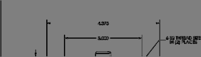
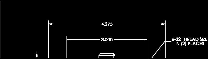
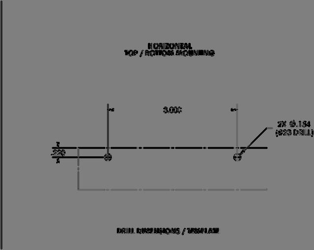
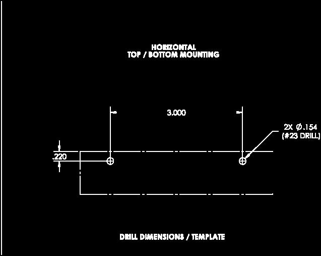
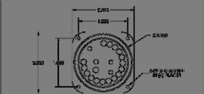
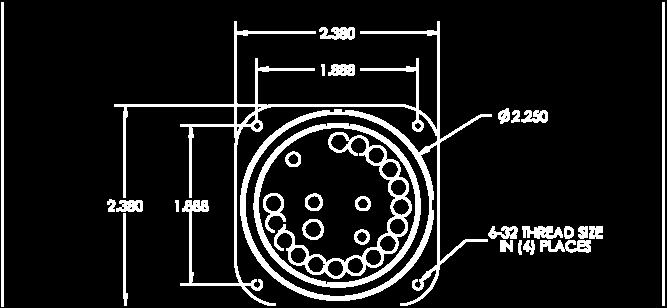
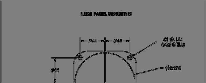
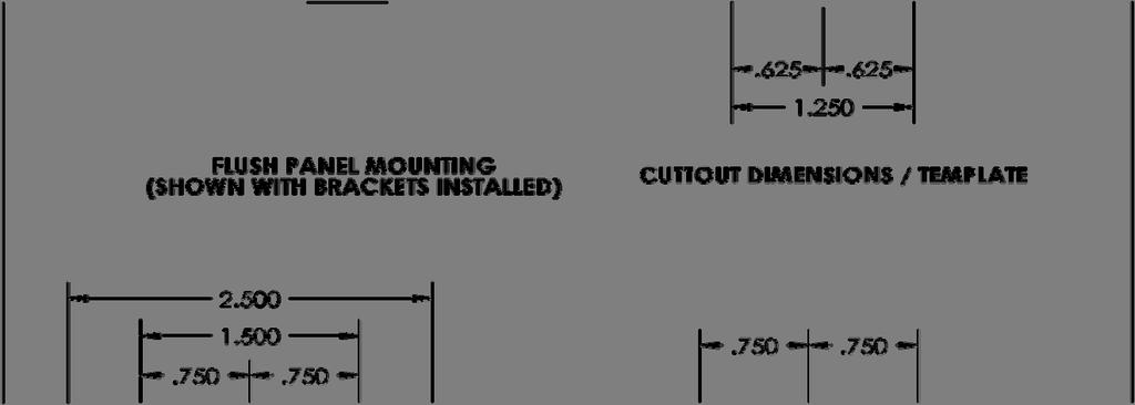
6 GENERAL 1.10 SPECIFICATIONS: Alpha Systems AOA Electronic version has 3 basic display sizes 1.) The Ultra, 2.5 long X ¾ wide X 1.0 deep 16 LED bar graph, 2) long X 1.00 wide X 1.00 deep 16 LED bar graph, 3.) The round display fits a standard panel opening with outside dimensions of: L X W X D.986. Display connector needs clearance opening of.500. All bar graph units have mounting holes on both sides and the back to facilitate vertical, horizontal, in panel, glare shield mounting possibilities. The Ultra 2.5 bar graph LED display has 2 optional dash mounts available to increase mounting capabilities above the glare shield in the pilots peripheral vision bar graph bar graph bar graph July 12, 2010 IOM-E, Rev. D 1.3


7 GENERAL July 12, 2010 IOM-E, Rev. D 1.4


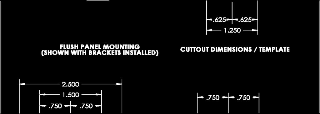
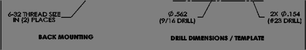
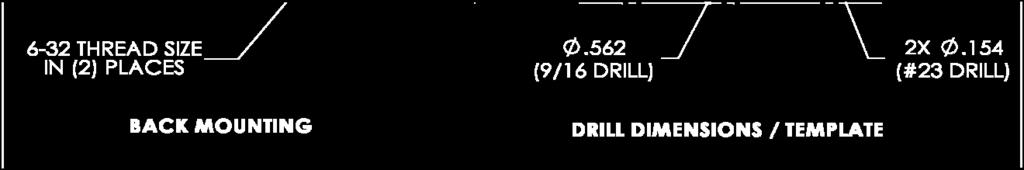
8 GENERAL Ultra 2.5 AOA standard dimensions Ultra 2.5 standard panel mount July 12, 2010 IOM-E, Rev. D 1.5


9 GENERAL Ultra 2.5, overall dimensions Ultra 2.5 Optional Vertical bracket for glare shield mount option Optional vertical dash mount bracket 2.5 July 12, 2010 IOM-E, Rev. D 1.6


10 GENERAL Ultra shield 2.5 Ultra Swivel mount Ultra 2.5 vertical mount bracket The Ultra 2.5 LED bar graph display can be mounted in the pilot s peripheral vision with the additional mounting kits. These mounting kits allow for accurate positioning in a vertical orientation above the aircrafts glare shield and mount with 4 mounting screws Aircraft Glare shield Swivel mount requires 1-¼ clearance below glare shield. Drill guide disk with 5 holes, included with Ultra swivel mount kit Surface mount swivel can be mounted on top of the glare shield or display inverted and mounted on a windshield frame. July 12, 2010 IOM-E, Rev. D 1.7


11 GENERAL The swivel mount drill guide disk is included with the mounting kit. It s used to aid in the drilling of the mounting holes for surface placement Hole 2 Hole 3 Hole 4 Hole 1 Step 1 Orient drill guide in location were swivel will mount, Using a #40 drill, drill hole, Cleco through hole, spin disk in final location. Step 2 When disk is in the final position, drill hole 2, Cleco, drill hole 3, Cleco, drill holes 4 and 5 Hole 5, starting hole for.720 clearance drill 4 Mounting holes and center clearance pattern on dash Step 3 Using Hole 5, drill for clearance swivel base of.720 Once the 4 outer holes are located and drilled, re-drill with a # 32 (.116 ) clearance for the 4-40 mounting screws, July 12, 2010 IOM-E, Rev. D 1.8


12 GENERAL AOA Interface Module Blue Hose From AOA Probe Display Connector White Hose I/O Connector Power in Connector Audio Beeper Power I/O Display System Description and Operation: The Alpha Systems electronic angle of attack system measures pressure at two points on a AOA probe and conveys those pressures, via sense lines, to the AOA interface module. The AOA interface module converts those pressures into an electronic signal that is transmitted to the display. The display interprets the signal and turns on the appropriate LED s to convey the angle of attack information to the pilot. In addition to the visual display the AOA interface module emits an 110Db aural (High Angle of Attack) warning tone. July 12, 2010 IOM-E, Rev. D 1.9


13 GENERAL The AOA probe must be mounted solidly in clean air flow, (undisturbed air) a minimum of 2 feet outside the prop ark, typically mounted 6 back from leading edge, 6 up from trailing edge, at any attitude, slip or skid NOTHING disrupting the direct air into the AOA probe. The AOA probe mounting plate WILL be cut to the shape of an existing inspection opening as outlined in this manual. After the mounting plate and probe are attached to the aircraft, it may become necessary to remove material on the mounting plate to allow the AOA probe to be adjustable past the 50 degree angle. July 12, 2010 IOM-E, Rev. D 1.10
14 PLANNING 2.1 Preparation: This chapter will guide you through the planning phase of the installation process. To prepare for the installation it is recommended that you read this manual in its entirety and complete this chapter prior to performing any work. 2.2 Establish the desired location of the angle of attack indicator. The angle of attack system is intended to provide supplemental information therefore it can not be used as a replacement for any required instruments. There is some good guidance in AC B Chapter 11 and FAR that refer to the location and installation of the instruments. Basically the instruments should be arranged in the standard T configuration with the angle of attack indicator preferably as high and left of the attitude indicator as possible. The location should also allow routing of the electrical wiring so it will not interfere with any moving controls or cables or come in contact will any line containing flammable fluids or gases. Since the display is electronic there are a number of other considerations that should be looked at, for example the intent of FAR is to cover installation of CRT or LCD displays that replace conventional analog instruments. Since the A.O.A. system does not replace any required instruments and does not involve a CRT or LCD display the regulation may not apply. Taking a conservative approach and showing compliance with this FAR can be done as follows: Electronic display instrument system o (a)(1) Arrangement and visibility; this requirement will have been met by complying with FAR o (a)(2) Be easily legible under all lighting conditions; this requirement has been met by design. The display is designed to be seen in direct sunlight and has a built in dimming device for lower levels of light. o (a)(3-7),(b)&(c) Does not apply since the system is a stand alone system and does not interface or replace any existing instruments or displays and is not considered essential for flight. Listed below are four different scenarios, find and complete the one that pertains to your installation and use the following formula when calculating the additional load: (Indicator Weight) X (Aircraft G Limit) X 1.5 (Safety Margin) = Additional Load Example:.5lbs X 6.6 X 1.5 = 4.95lbs. IF you are planning to install the indicator in an existing hole on the instrument panel then a determination is needed to insure that the fasteners/shock mounts will accept the additional load of the indicator. This is an easy one, the indicator only weighs.5lbs (or less, depending on the model) so the addition of the indicator should not normally exceed the limits of the mounting hardware. This is a preferred method of installing the indicator and in most cases will require no additional alterations, hence a minor alteration. Please refer to AC B Chapter 1 and Chapter 2 paragraph 203(a-e) for guidance. IF you are planning to install the indicator in a panel that is shock mounted and has no existing mounting hole present you will need to make two determinations. First, will the shock mounts accept the additional load of the indicator and secondly, will the panel be strong enough with an additional instrument hole in it. The indicator only weighs.5lbs (or less, depending on the model) so the addition of the indicator should not normally exceed the limits of the shock mounts. The panel strength should July 12, 2010 IOM-E, Rev. D 2.1
15 PLANNING not be an issue if you keep the hole spacing the same as the original panel layout. This is also a preferred method of installing the indicator and in most cases will require no additional support structure, hence a minor alteration. Please refer to AC B Chapter 1 and Chapter 2 paragraph 203(a-e) for guidance. IF you are planning to install the indicator on a glare shield you will need to make a determination that the structure is strong enough to support the weight of the indicator. This is also a preferred method of installing the indicator and in most cases will require no additional support structure, hence a minor alteration. Please refer to AC B Chapter 1 and Chapter 2 paragraph 205(a-c) for guidance. IF you are planning to install the indicator in a panel where no mounting hole is present and the panel is not shock mounted several determinations will be required. First is the panel non-structural? If so, you will need to determine that the mounting hardware will accept the additional load of the indicator and will the panel be strong enough with an additional instrument hole in it. The indicator only weighs.5lbs (or less, depending on the model) so the additional load of the indicator should not normally exceed the limits of the mounting hardware. The panel strength should not be an issue if you keep the hole spacing the same as the original panel layout. This method of installing the indicator will, in most cases, not require additional support structure, hence a minor alteration. If the panel you intend to install the indicator in is a structural panel, than this would be considered a major alteration and engineering data may be required and should be obtained prior to any work being performed. Please refer to AC B Chapter 1 and Chapter 2 paragraph 203(a-e) for guidance. 2.3 Establish the desired location for the AOA interface module: The AOA interface module is used to convert pressures, measured at two points on the probe, to an electronic signal that is then delivered to the indicator which displays angle of attack information to the pilot. The AOA interface module may be physically installed just about anywhere observing the following limitations: On a structure that will support the additional load of the module. The sense lines shall not interfere with any moving controls or cables. The electrical wiring shall not interfere with any moving controls or cables and shall not come in contact with any line containing flammable fluids or gases. The AOA interface module must be bonded to the airframe, (grounded for shielding). Mounted within six feet of the indicator. * Mounted within six feet of the power source or the optional on/off switch. * *Note: If a longer cable is required it may be possible to have a longer custom cable assembly fabricated, contact Alpha Systems for more information. Use the following formula when calculating the additional load: (Module Weight) X (Aircraft G Limit) X 1.5 (Safety Margin) = Additional Load Example:.8lbs X 6.6 X 1.5 = 7.92lbs. July 12, 2010 IOM-E, Rev. D 2.2
16 PLANNING If the module can be installed without adding additional support structure than is would normally be a minor alteration. Please refer to AC B Chapter 1 and Chapter 2 paragraphs 201, 202, for guidance. 2.4 Establish the desired location on a wing for the probe with the following limitations: Minimum of 24 outboard of the propeller arc. Minimum of 12 inboard of the wing tip. At least 6 outboard of any struts or landing gear. Between 10% to 90% of the mean aerodynamic cord (MAC). Must not be mounted on a wing incorporating a remote compass system if probe heat is to be installed. Listed below are three different scenarios, find and complete the one that pertains to your installation and use the following formulas when calculating the additional load and drag: (Probe + Hardware Weight) X (Aircraft G Limit) X 1.5 (Safety Margin) = Additional Load Examples:.6lbs X 6.6 X 1.5 = 5.94lbs. (Drag Coefficient) X (Frontal Area of the Probe) X VNE² = Drag in LBS at VNE X.064 X 200² = IF a non-structural inspection panel is available determine that the existing structure will support the additional load and drag of the probe and mounting hardware. Please refer to AC B Chapter 1 & Chapter 3 for guidance. This is the preferred method of installing the probe and in most cases will require no additional support structure, hence a minor alteration. However, if you have a very fast and/or a thin skinned aircraft the addition of supporting structure may be required, if so that would be considered a major alteration. IF a structural panel is available and used to support the probe this would be considered a major alteration. Engineering data may be required and should be obtained prior to any work being performed. Please refer to AC B Chapter 4, AC B Chapter 1 & Chapter 3 for guidance. IF no inspection panel is available to support the probe, an inspection hole along with a doubler and/or supporting structure may be installed in the wings skin. This would also be considered a major alteration and engineering data may be required and should be obtained prior to any work being performed. Please refer to the airframe manufactures maintenance manual, AC B Chapter 4, AC B Chapter 1 & Chapter 3 for guidance. July 12, 2010 IOM-E, Rev. D 2.3
17 PLANNING 2.5 Establish a plan to route the sense lines through the aircraft structure with the following limitations: Do not remove hose end caps until final connector installation. Minimum bend radius of 4 for the lines must be observed. Attach lines at regular intervals by means of suitable clamps. Do not clamp lines at the end fittings. Use AN931 Grommets (preferred) or bulkhead fittings where they pass thru bulkheads. Engineering data may be required if entering a pressure vessel. Keep well clear of any moving controls or cables. Refer to the airframe manufactures maintenance manual and AC B Chapter 12 Section 4 for instructions on replacing/installing new pitot static lines. 2.6 Establish a plan for the electrical power: The electronic A.O.A. system requires less than ¼ amp (250 ma) of electrical power within its acceptable voltage range of 10-28VDC. Our recommendations would be to have the A.O.A. draw power from the avionics bus through an on/off switch in series with the positive lead for the control module (this would offer some protection from surges during starts and the on/off switch would enhance operational flexibility). Based on the very low power requirements this system may be installed as a minor alteration. However since it is an electronic display there are a number of other considerations that should be looked at first before that determination is made. We will take you step by step through the applicable regulations and explain the pertinent parts Instrument using a power source o (a) Power Indicator; this requirement has been met by design; loss of power is indicated by all lights off (i.e. no deceptive indications). o (b)(1&2) Installation and power supplies; these requirements have been met by design; the system does not interface with any other instruments or displays and the control module is shielded and utilizes MIL spec shielded wire as an added safe guard to prevent any interference. o (c) Two independent power sources; this requirement may be met on aircraft equipped with two different power sources connected to the same electrical bus that the A.O.A. system receives power. For example, an aircraft with the following equipment connected to the electrical bus that supplies the A.O.A. system would satisfy this requirement: an engine driven generator/alternator and a storage battery and a means to indicate the batteries proper state of charge and is monitored and displayed to the pilot Electrical, general o (a)((1&2) Electrical loads; if the electrical system was adequate prior to the installation the additional load of the A.O.A. system would be considered negligible and thus would not have any appreciable effect. The key here is the electrical system must be considered adequate before adding any additional loads. o (b) Function of each electrical system; if the electrical system is not altered to affect methods of operation and is free from hazards this part would be complied with. July 12, 2010 IOM-E, Rev. D 2.4
18 PLANNING Circuit protective devices. o (a) Protective device; a circuit protection device must be installed for this installation. We recommend that you use the same type and manufacturer that is already installed (1 amp). o (b) Essential circuit; the A.O.A. system power can not be connected to a circuit that protects essential equipment. We recommend that an additional circuit protection device be installed and labeled in the same manner as the original aircraft manufacturer. o (c)(1&2) Re-settable circuit protective device; requires a manual reset and will only reset once the overload is eliminated regardless of position of the operating control, again if you use the same as the original manufacturer this regulation will be satisfied. o (d) Is not applicable. o (e)(1&2) Fuse replacement; if you use a fuse for a circuit protection device that is intended to be replaced in flight you must carry spare fuses that are readily accessible to each required pilot Wire analysis. o (a.) Capacity; the power cable incorporates #22 shielded MIL Spec. wire and is sized correctly for the length supplied. If the optional switch is installed, wire size is determined by the wire length (considering its routing from the circuit breaker/fuse through the switch to the AOA interface module and to an adequate ground) and the load of.25 amps. Determine the size of wire required from AC B Chapter 11 Section 5 (for 14VDC in free air #22 wire will be adequate for runs up to 29 feet & for 24VDC in free air #22 wire will be adequate for runs up to 60 ). o (b.) Flame and toxic fume resistant; the wire supplied with the AOA interface module is MIL Spec. shielded wire and meets these requirements. If additional wire is used use MIL Spec. wire to comply with this requirement. o (c.) Not applicable. o (d.) Identification; this is complied with by design, the cables supplied with the system are identified with a heat shrink label. If additional wiring is needed colors, numbering or labeling can be used to ID the wire, it can be as easy as using a permanent marker to ID the wire. o (e.) Installation and routing. Electrical cable/wire must be installed such that the risk of mechanical damage and/or damage caused by fluids, vapors, or sources of heat, is minimized Switching;(if the Optional on/off switch is installed) Each switch must be, o (a) Able to carry its rated current; o (b) Constructed with enough distance or insulating material between current carrying parts and the housing so that vibration will not cause shorting; o (c) Accessible to appropriate flight crewmembers; and o (d) Labeled as to operation and the circuit controlled. We recommend that you use a MIL Spec. switch with silver contacts rated for twice the required amperage (i.e. Honeywell 1TW1-2, MS SPST switch). If the regulations are complied with as described above the A.O.A. system can be connected to the aircraft electrical system as a minor alteration. For additional information July 12, 2010 IOM-E, Rev. D 2.5
19 PLANNING please refer to AC B Chapter 11, which has a wealth of information on wire, switches, loads, etc., also AC B Chapter 2 paragraph 207 is useful. 2.7 Optional probe heat installation: The optional probe heat requires 7.2 amps of electrical power at 14 or 24VDC. For this reason this installation would be considered a major alteration. We will take you step by step through the applicable regulations and explain the pertinent parts Electrical load analysis; o (a)((1&2) Electrical loads; the electrical system must be adequate for the intended use. What this means is that the additional load of the probe heat would not degrade the ability of the electrical system to furnish the required power at the proper voltage to each load circuit essential for safe operation, considering an electrical load analysis or by electrical measurements that account for the electrical loads applied to the electrical system in probable combinations and for probable durations. The key here is the electrical system must be considered adequate before adding any additional loads and have additional capacity to handle the load of the probe heat without degrading the system. The old rule of thumb was electrical load analysis would require the load imposed by installed equipment not to exceed 80% of your generator/alternators capacity. Understanding the term probable combinations and for probable durations gives the installer a little more latitude in the electrical load analysis. o (b) Function of each electrical system; if the electrical system is not altered to affect methods of operation and is free from hazards this part would be complied with Circuit protective devices o (a) Protective device; a circuit protection device must be installed for this installation. We recommend that you use the same type and manufacturer that is already installed (10amp). o (b) Essential circuit; the probe heat can not be connected to a circuit that protects essential equipment. We recommend that an additional circuit protection device be installed and labeled in the same manner as the original aircraft manufacturer. o (c)(1&2) Re-settable circuit protective device; requires a manual reset and will only reset once the overload is eliminated regardless of position of the operating control, again if you use the same as the original manufacturer this regulation will be satisfied. o (d) is not applicable. o (e)(1&2) Fuse replacement; if you use a fuse for a circuit protection device that is intended to be replaced in flight you must carry spare fuses that are readily accessible to each required pilot. July 12, 2010 IOM-E, Rev. D 2.6
20 PLANNING Wire analysis. o (a.) Capacity; is determined by the wire length (considering its routing from the circuit breaker/fuse through the switch to the probe heater and to an adequate ground) and the load of 7.2 amps. Determine the size of wire required from AC B Chapter 11 Section 5, (14VDC in free air #14 wire will be adequate for runs up to 20 & for 24VDC in free air #16 wire will be adequate for runs up to 25 ). As an added precaution to prevent interference with other aircraft systems use MIL Spec shielded wire. o (b.) Flame and toxic fume resistant; use a MIL Spec. wire and you will have met these requirements. o (c.) Not applicable. o (d.) Identification; colors, numbering or labeling can be used to ID the wire, it can be as easy as using a permanent marker to ID the wire. o (e.) Installation and routing. Electrical cable/wire must be installed such that the risk of mechanical damage and/or damage caused by fluids, vapors, or sources of heat, is minimized. Route as far away as possible from any instrument, system or wiring that may be effected (i.e. compass/flux gate, antenna or antenna coax) Switching; Each switch must be, o (a) Able to carry its rated current; o (b) Constructed with enough distance or insulating material between current carrying parts and the housing so that vibration in flight will not cause shorting; o (c) Accessible to appropriate flight crewmembers; and o (d) Labeled as to operation and the circuit controlled. We recommend that you use a MIL Spec. DC switch with silver contacts rated for twice the required amperage (i.e. Eaton 8500K9, MS SPST switch). AC B Chapter 11 has a wealth of information on wire, switches, loads, etc. also AC B Chapter 2 paragraph 207 is useful. July 12, 2010 IOM-E, Rev. D 2.7
21 PLANNING 2.8 Review your plans and determine that it meets the requirements of the following regulations: : (a) is it of a kind and design appropriate to its intended function? If you intended to add an angle of attack system and can do it as described above than the answer is yes. (b) Can it be labeled as to its identification, function? The indicator meets this identification requirement for the indicator. However, if you install the optional on/off switch or probe heat than you are required to label the switch(s) and circuit breaker(s) as to their function. (c) Can it be installed according to limitations specified? You must meet all specified requirements to answer this yes. If you answered any of the above questions with a NO then revise your plan until you can answer all the questions with a YES : (a)(1) When performing its intended function will it adversely affect the response, operation or accuracy of any: (i) Equipment essential to safe operations? If the A.O.A. system is installed correctly it should not affect any other equipment as it is a stand alone system which does not interface with any other equipment, one exception is the optional probe heat which must be looked at very closely. (ii) Other equipment unless there is a means to inform the pilot of the affect? Same as above, additionally do not utilize a circuit breaker shared with any other piece of equipment for the A.O.A. system or the probe heat in an effort to avoid this situation. Refer to AC D Section 9, it will help you answer the questions and the flow chart makes it easy to determine if the installation will meet the requirements of (a). If you answered either of these two questions with a YES then revise your plan until you can answer them both with a NO. If you made it through all this successfully, you are doing great, and are now ready to install the Alpha Systems AOA, Angle of Attack System in your aircraft. July 12, 2010 IOM-E, Rev. D 2.8


22 INSTALLATION 3.1 Preparing to install the probe: In chapter two the location for the probe was established. If it was determined that additional structure or modification to the wing will be required, perform that work now in accordance with the established plan and or any required engineering data. If not already done so, remove the inspection panel at the location were the probe will be mounted. Modify the probe mounting plate to fit the hole (the panel removed may be used as a template). Ensure that the slot in the mounting plate is aligned so that the rounded end of the slot faces forward. AOA PROBE STARTING ANGLE On a non-structural panel the screw spacing should be no less than 1 screw every 2 to 3 inches along the outside circumference of the mounting plate. If the existing layout is greater add nut plates as required to accomplish the proper screw spacing (on a structural panel the screw spacing would be much closer). Drill holes in the probe mounting plate to match the layout in the wing. Install the mounting plate on the wing and check for proper fit. When satisfied remove the panel and prepare the panel for paint. Finish panel as desired and set aside to cure. 3.2 Install the AOA sense lines. Gain access to the aircraft so that the AOA sense lines can be installed and routed through the aircraft from the probe location to the AOA interface module location in accordance with the plan established in chapter two. Route the AOA sense lines and observe the following requirements: Minimum bend radius of 4. Attach lines at regular intervals by means of suitable clamps. Do not clamp lines at the end fittings. Use AN931 Grommets (preferred) or bulkhead fittings where they pass thru bulkheads. Do not remove the caps installed on either ends of the sense lines and leave sufficient length so they may be cut to length later in the installation process. Keep the lines well clear of any moving controls or cables. July 12, 2010 IOM-E, Rev. D 3.1
23 INSTALLATION 3.3 Install the wiring, switch & circuit breaker for the A.O.A. system. NOTE: It may be advantageous to perform the steps found in section 3.4 at the same time the following work is performed if the optional probe heat is to be installed. In chapter two a plan was established so that the requirements for supplying power to the A.O.A. system were satisfied, in accordance with that plan: Ensure that the aircraft electrical system is NOT powered and the aircraft battery is disconnected. Install the circuit breaker. Mount in a manner accessible to a crewmember during flight for circuit breaker resetting. Identify and label the circuit breaker. Optional, install the on/off switch so it is accessible to appropriate crewmembers. If installed, label the switch as to its operation. Route the cable/wire from the circuit breaker to the on/off switch, if installed, then to the control module location, observing the following: o Keep wires well clear of any moving controls or cables. o Physically separate electrical wire from lines or equipment containing oil, fuel, hydraulic fluid, alcohol or oxygen. o Route wires above flammable fluid lines and securely clamp to structure, in no case may a wire be clamped to line containing flammable fluids. Connect the White wire (NO stripe) to power (+) Connect the White wire WITH Blue stripe to an adequate ground ( - ). If additional wire was used ensure the wire is identified / labeled. Attach the shielding together at a break in the wire (i.e. at the switch) and ensure it is insulated so as to prevent contact with any other conductor. Do not connect the shield to ground as it is grounded at the connector, doing so would cause a ground loop. Recheck for proper polarity, (+) White wire, ( - ) White with Blue stripe (Ground). July 12, 2010 IOM-E, Rev. D 3.2
24 INSTALLATION 3.4 Install the wiring, switch and circuit breaker for the probe heat. Note: this section may be skipped if the optional AOA probe heat is not to be installed. In chapter two a plan was established so that the requirements for installing the probe heat were satisfied, in accordance with that plan: If not already done so, ensure that the aircraft electrical system is NOT powered and the aircraft battery is disconnected. Install the circuit breaker. Mount in a manner accessible to a crewmember during flight for circuit breaker resetting. Identify and label the circuit breaker. Install the switch so it is accessible to appropriate crewmembers. Label the switch as to its operation. Label the wire so it may be identified once installed. Install the wire from the circuit breaker through the switch to the probe location and to a suitable ground observing the following: Physically separate electrical wire from any lines or equipment containing oil, fuel, hydraulic fluid, alcohol or oxygen. Route wires above any flammable fluid lines and securely clamp to structure, in no case may a wire be clamped to line containing flammable fluids. Route as far away as possible from any instrument, system or wiring that may be effected (i.e. compass/flux gate, antenna or antenna coax). Leave sufficient wire at the probe location so it may be cut to length and connected to the probe later in the installation process. Attach the shielding to a suitable ground on one end of the wire only, this will prevent a ground loop. Attach the shielding together at a break in the main conductor (i.e. at the switch connections) and ensure it is insulated so as to prevent contact with any other conductor. July 12, 2010 IOM-E, Rev. D 3.3
25 INSTALLATION 3.5 Install the AOA indicator: In chapter two the location for the AOA indicator was established. If it was determined that additional structure or modification to the instrument panel will be required, perform that work now in accordance with the established plan and or any required engineering data. Install the AOA indicator and check for fit and clearances. If installing a 2¼ instrument ensure the 6x32 screws are no longer then 1/4" plus the mounting panel thickness. The vertical or horizontal indicator may be mounted using any two of the six threaded (6x32) mounting holes. If utilizing side holes the screw can not be any longer than 1/4" plus the mounting panel thickness. If utilizing the rear holes the screws can be no longer than 1/8 plus the mounting panel thickness. The angles provided with the mounting kit are provided to aid in mounting the indicator and their use is not mandatory. Route the cable from the AOA indicator to the AOA interface module location, observing the following: o Keep wires well clear of any moving controls or cables. o Physically separate electrical wire from lines or equipment containing oil, fuel, hydraulic fluid, alcohol or oxygen. o Mount electrical wire bundles above flammable fluid lines and securely clamp to structure, in no case may a wire be clamped to line containing flammable fluids. 3.6 Install the AOA interface module. In chapter two the location for the AOA interface module was established. If it was determined that additional structure or modification will be required, perform that work now in accordance with the established plan and or any required engineering data. Attach the AOA interface module to the airframe utilizing the mounting base plate. The AOA Interface module must be grounded for shielding. If the module is not grounded by the mounting hardware install a grounding strap from one of the mounting screws to a suitable ground. Cut the AOA sense lines (at a 90 angle, NO burs) to length and insert the lines firmly in the connectors, observe the color coding, BLUE / FRONT TO BLUE LINE AND WHITE / BOTTOM TO WHITE LINE. When correctly installed the line will be inserted approximately 3/8 into the connector. Push hose in connector until it stops. Ensure the line is installed correctly by giving the line a light pull and if the line does not back out it is a good connection. If you ever need to disconnect the lines depress the black collar (the furthest outboard portion of the connector) on the fitting and pull the line out. See help sheet included with manual. July 12, 2010 IOM-E, Rev. D 3.4


26 INSTALLATION AOA Interface Module FROM AOA PROBE BLUE HOSE WHITE HOSE DISPLAY CONNECTOR I/O CONNECTOR AUDIO BEEPER POWER CONNECTOR Connect the display cable connector (6 Pin) to the AOA interface module display connector, they are both color coded BLUE. This may be accomplished by holding the cable connector by its black strain relief and rotate it on the display connector until the alignment keyways mate up then push towards the AOA interface module and the retaining collar will snap into place tightly against the AOA interface module. Verify connector is seated completely by pulling lightly on wire and connector stays on AOA interface module. Connect the power cable connector (4 PIN) to the AOA interface module power connector, they are both color coded RED. This may be accomplished by holding the cable connector by its black strain relief and rotate it on the power connector until the alignment keyways mate up then push towards the AOA interface module and the retaining collar will snap into place tightly against the AOA interface module. Verify connector is seated completely by pulling lightly on wire and connector stays on AOA interface module. To remove either of the electrical connectors grip the collar and pull away from the AOA interface module and slide the connector off. Note: The center connector labeled I/O, color coded yellow, is for future use and should have the protective cover installed. 3.7 Install the AOA probe and mounting plate. (Optional), if installing a heated probe, it will come from the factory installed with high temperature fittings and colored (Blue / White) high temperature hoses with heater in AOA probe. Install the probe in the modified mounting plate and secure it by inserting the AN4 bolt through the mounting plate and probe. Install the washer and nut, tighten it so the probe will not move in flight but will allow adjustments without loosening the nut. Optional, cut the electrical wires for the probe heat to length and connect them to the heater, polarity is not an issue, connect power to one lead and ground the other. Attach the shielding to a suitable ground on one end of the wire only; this will prevent a ground loop. July 12, 2010 IOM-E, Rev. D 3.5


 on the fitting and pull the line out.")

27 INSTALLATION Cut the AOA sense lines (at a 90 angle, verify NO burs) to length so they may be easily attached to the probe but short enough so they will not kink when the mounting plate is secured to the wing. Allow enough hose to re-position AOA probe angle for final adjustments. Insert the lines firmly in the connectors, observe the 2 letters (B & W) on the side of the AOA probe, B (for Blue, Front Hole) TO BLUE LINE and W (for White, Bottom Hole) TO WHITE LINE. When correctly installed the line will be inserted approximately 3/8 into the connector. Push hose in firmly until a positive stop. Ensure the lines are installed correctly by giving the line a light pull and if the line does not back out it is a good connection. If you ever need to disconnect the lines depress the black collar (the furthest outboard portion of the connector) on the fitting and pull the line out. Slowly slide the probe and mounting plate into position ensuring that everything will fit properly and not kink or bind. When satisfied, secure the mounting plate to the wing and tighten all screws. Adjust the AOA probe to the initial 50 angle, tighten bolt and nut snugly so that the probe will stay in position and not move in flight. If needed, the probe can be repositioned with a firm pull or push on the ground to correct for mounting AOA probe value errors. It may be necessary to remove material on the mounting plate that prevents the probe to be installed properly. If the 50 (or less) angle of the AOA probe interferes with the plate or in the final calibration steps, the probe to be at a tighter angle, remove material as required. July 12, 2010 IOM-E, Rev. D 3.6
28 INSTALLATION 3.8 Inspect the A.O.A. installation, perform initial ground calibration: Inspect in the areas that were opened to install the A.O.A. sufficiently so you can determine hat the installation was done correctly and no discrepancies are left unresolved. Connect the aircraft battery. Close any open circuit breakers for the A.O.A. system and probe heat. Power up the aircraft electrical system and turn on the A.O.A. system and probe heat, (if installed). Disregard any A.O.A. indications at this time. The AOA display will be flashing ALL LED s, this indicates ALL calibrations need to be made BEFORE it is functional. Re-inspect the areas that were opened to install the A.O.A. system, paying particular attention to the electrical part of the installation, determine that there are no unresolved issues with the electrical part of the installation. If probe heat was installed check the operation of the probe heat with the switch in the on and off position. Ensure the compass or other systems are NOT affected by the probe heat. When finished place the probe heat off. CAUTION BURN HAZARD: When checking the A.O.A. probe heater, DO NOT TOUCH THE AOA PROBE! Use a thermometer or place your hand above the probe to feel the radiated heat. Leaving the probe heat on for extended periods while on the ground, will shorten its service life. (ON THE GROUND) CALIBRATION PROCEDURES Perform the (On the Ground) Zero Pressure Calibration (Step 1) procedure utilizing the flow chart found in figure 3.1 or the amplified procedures in section 3.9. This next step is optional and can be done as required. Perform the ( On the Ground) Brightness Calibration procedure utilizing the flow chart found in figure 3.2 or the amplified procedures in section 3.9. Power off the aircraft electrical system. Close the aircraft up by installing any access panels or equipment removed to install the A.O.A. Once the system has had the Zero Pressure calibration set, is not necessary to reenter the Zero Pressure calibration if power is removed. The system stores the value. July 12, 2010 IOM-E, Rev. D 3.7
29 INSTALLATION STEP 1 ZERO CALIBRATION (On the Ground) Setting the Zero Pressure Electrical System OFF NEXT While Pressing the CAL button on the AOA Display, Turn power ON to the system and continue to hold down the CAL BUTTON for 5 seconds. Press and hold the CAL button, turn power ON, hold for 5 sec. RELEASE BUTTON LED s ARE STILL FLASHING NO ALL LED s have stopped flashing after a few seconds & the Blue & the last Green LED flash 5 times YES BLUE LED & LAST GREEN LED FLASHED 5 TIMES Bad Zero Pressure Offset (too high) Power OFF system and check for mechanical / electrical faults with the system Good Zero Pressure Point Release the CAL button System will now enter the inactive Display mode Causes: - Air Hose is kinked - Air Hose is obstructed by foreign matter - Electrical failure with the system To isolate failure: Disconnect the air hoses from the AOA interface module and repeat the procedure. If the condition is gone, the failure is mechanical If the condition persists, the failure is probably electrical related Figure 3.1 Step 1: Complete After the unit has accepted the ground calibration value, the Blue LED and the last Green LED on the AOA Display will flash 5 times to indicate that the OAA and Cruise set points need to be calibrated. The AOA Display is set to INACTIVE until In-Flight Calibration Mode, Step2 is entered. Step 1: (On the Ground) Zero calibration overview When the system installation and electrical connections are completed, Electrical and pressure zero set points need calibration. When the unit is first turned on, All LED s will flash indicating the unit needs to have the Zero calibration procedure completed. The ground calibration set point can be reset at any time after the initial calibration however ALL in-flight set points must be reset and identified. July 12, 2010 IOM-E, Rev. D 3.8
30 INSTALLATION Setting the Display Brightness (on the ground) Electrical System OFF NEXT While Pressing and holding the Brightness button on the AOA Display, turn system power ON, Wait 4 sec. release the Brightness button Night time Brightness The brightness levels on the display can be set on the ground and all of the LED s turned on by following this procedure. Both the day time and night time brightness levels can be adjusted and set. Both levels can be changed in the cockpit, in flight, at any time. There are 16 brightness levels, cycling through to the maximum, then starts over from the lowest. Press and release until desired brightness. All the LED s on the display are illuminated. Cover the photo cell opening and continuously press and release the Brightness button until the desired NIGHTTIME BRIGHTNESS level is achieved Day time Brightness With A light shining on the photo cell opening, continuously press and release the Brightness button until the desired DAYTIME BRIGHTNESS level is achieved Cover Photo Cell here for DARK setting or shine light for DAYTIME setting NEXT Power Electrical System OFF NEXT When the system is powered ON the next time, the system will respond in 1 of 2 ways NEXT NO The Blue LED and the last Green LED will flash 5 times indicating (OAA) and Cruise Setpoints need to be entered Have the (OAA) Optimum Alpha and Cruise Set points been calibrated? YES (Inactive display) Not functional, Needs to be calibrated The system will enter the Operational Display Mode (COMPLETELY FUNCTIONAL) Setpoints have been entered and when in-flight will display the AOA of the aircraft as previously set. Figure 3.2 July 12, 2010 IOM-E, Rev. D 3.9
31 INSTALLATION 3.9 Amplified (On the ground) calibration procedures: When the system is first powered on, ALL LED s on the AOA DISPLAY should continuously flash on and off simultaneously, indicating a non-calibrated system. Step 1 (On the Ground) Calibrating the Zero Pressure Point This must be done in a zero pressure condition, preferably in a calm environment such as a hanger or no wind environment. While pressing the CAL button on the AOA DISPLAY, apply power to the system. Continue pressing the CAL button for about 8 to 10 seconds after power has been applied. All the LED s stop flashing after a few seconds (see note below), this indicates the Zero Pressure value at the sensor is good and will be stored to system EEPROM and used as the system zero pressure point. Releasing the CAL button, the AOA DISPLAY will enter its diagnostic LED illumination routine in which all LED s are illuminated one by one upwards and then one by one downwards than enter an inactive Display mode. At this point the operator needs to calibrate the rest of the system. Refer to the next sections. Otherwise: If all LED s on the AOA DISPLAY continue to flash on and off, the Zero Pressure value at the sensor is too high, which indicates something is wrong electrically or mechanically with the system, or something in the environment is affecting the system. The system will flag the bad Zero pressure value and continue to flash all LED s, even if the system is powered off and on, until an acceptable zero offset has been detected by repeating the above procedure. To isolate the failure between mechanical or electrical, the air hoses should be disconnected from the AOA interface module and the above operation repeated. If the condition persists, then the failure is electrical and the AOA interface module should be returned for an authorized repair. If the setting is successful, then the failure is mechanical such as a blockage in the air hoses, etc. Once the mechanical failure is fixed, the above operation should be repeated. Note: This is a power on procedure. Because there is power ON settling time for the electronics, ALL LEDS on the AOA DISPLAY may flash several times before the system electronics stabilize and then stop flashing for an acceptable / valid zero pressure point that can be stored. July 12, 2010 IOM-E, Rev. D 3.10
32 INSTALLATION Setting the Brightness of the LED s (On the Ground) This step will allow the Night time and Day time brightness levels be set on the ground. Both the day time and Night time levels can be changed at any time while in flight. This procedure makes it possible to preset the brightness before the in flight calibration steps are completed. Press and hold the Brightness button on the AOA DISPLAY, Turn power ON. Continue to hold the Brightness button depressed for about 4 seconds, release Brightness button. The system will enter the diagnostic LED illumination routine, all LED s are illuminated one by one upwards, then one by one downwards and end with ALL the LED s being illuminated. The system has entered the Brightness calibration mode. Night time Brightness set point Cover the photo diode on the AOA DISPLAY with your thumb or a piece of black electrical tape. Press and release the Brightness button on the AOA DISPLAY cycling through the brightness steps until the display is at a minimum or lowest level. This sets the Night time brightness initial setting. Uncover the photo cell Day time Brightness set point With a light applied directly to the photo diode on the AOA DISPLAY, press the Brightness button on the AOA Display cycling through the brightness steps until the display is at the maximum brightness (you ll know when it s max because going past it will cause the brightness of the LED s to return to the minimum level). Wait about 5 seconds for the unit to store the setting. Remove the light from the Display. The LED s brightness will change to lower brightness unless the low light setting was set to maximum brightness or the cockpit is in daylight. Remove power, wait a few seconds and re-apply power. The system should enter its diagnostic LED illumination routine in which all LED s are illuminated one by one upwards and then one by one downwards and then enter the active or in-active Display mode, dependent on whether the system has been calibrated or not. You know the old saying, it s not finished until the paper work is done. Please refer to chapter four and document your work. July 12, 2010 IOM-E, Rev. D 3.11
33 DOCUMENTATION 4.1 Background information: The Alpha Systems Angle of Attack System (AOA) may be installed on many aircraft models numerous ways. For this reason we can not point you to a boiler plate logbook entry or sign off that will be good for all aircraft. We will help you through the documentation process by explaining pertinent topics and direct you in the proper direction by employing those topics in sample logbook entries. 4.2 Major vs. Minor Alteration: In subject 1.3 we discussed the difference between a major and minor alteration, again a minor change is one that has no appreciable effect on the weight, balance, structural strength, reliability, operational characteristics or other characteristics affecting the airworthiness of the product. In Chapter 2 some scenarios were listed that may in our judgment make the installation a major alteration; however this determination is the responsibility of the person performing the installation. If a determination was made that: The alteration was a minor alteration, the aircraft can be returned to service by an appropriately rated mechanic or by an individual that holds a repairman s certificate for that specific aircraft by documenting the alteration in the aircraft records. The alteration was a major alteration, the FAA must be informed. The form used to report the alteration and the FAA s response shall be determined by what part of the FAR s the aircraft was certified under. For example: If a certified mechanic with Inspection Authorization (IA) makes a major alteration to a type certificated aircraft using approved data (STC s, AD s, etc.) he/she must simply report that alteration to the FAA on a form 337 by mailing it to them at Oklahoma City within 48 hours of returning the aircraft to service, no response is required by the FAA. If a certified mechanic with Inspection Authorization (IA) intends to make a major alteration to a type certificated aircraft using acceptable data (i.e. AC B, AC B, etc.) he/she must submit a FAA form 337 to the local FSDO describing the work to be completed referencing that acceptable data prior to commencing the work. The FAA s response will normally be to approve the acceptable data by signing block 3 on the 337 form and returning it to the mechanic, this is referred to as a Field Approval. Once the alteration is completed and the aircraft is returned to service the mechanic must mail the completed 337 form to the FAA at Oklahoma City within 48 hours of returning the aircraft to service. If a certified mechanic or a person holding a repairman s certificate for a specific experimental aircraft make or intend to make a major alteration to that aircraft they must report that alteration to the cognizant FSDO and receive a written response prior to further flight. There is no specific form that must be used to report the alteration; however the FAA will use the data you submit to determine if your alteration would require your aircraft to be returned to Phase 1 for further flight testing. So it would be to your benefit to report the alternation using references of acceptable data so your aircraft will not be returned to Phase 1 unnecessarily. July 12, 2010 IOM-E, Rev. D 4.1
34 DOCUMENTATION 4.3 Logbook entries: The pertinent parts of FAR 43.9 (in italics) that describes the requirements for content, form, and disposition of alteration records that pertain to the A.O.A. installation are listed below. I will attempt to explain the intent of the FAR as it applies to this installation. (a)each person who maintains, performs preventive maintenance or alters an aircraft shall make an entry in the maintenance record of that equipment containing the following information: (1) A description (or reference to data acceptable to the Administrator) of work performed. (The FAA would like a description of the work completed and under what authority was this alteration done. Your description of the work along with references to acceptable data satisfies this requirement. Acceptable data, listed in chapter two of this manual, may be used to support the description of the alteration.) (2) The date of completion of the work performed. (Self explanatory.) (3) The name of the person performing the work if other than the person specified in paragraph (a)(4) of this section.(if work was performed on an airframe by anyone who does not hold an airframe mechanic/repairmen certificate, which is allowed under the authority of FAR 43.3(d), their name should be included in the logbook entry.) (4) If the work performed on the aircraft has been performed satisfactorily, the signature, certificate number, and kind of certificate held by the person approving the work. The signature constitutes the approval for return to service only for the work performed. (The FAA wants to know who is responsible for returning the aircraft to service. This could vary from a private pilot performing preventive maintenance in accordance with 43.3(g) to an A&P mechanic with IA returning a certified aircraft to service after a major alteration. Please refer to subject 4.2 for a more in depth explanation of who can return your aircraft to service after the installation of the A.O.A. system.) (d)in addition to this entry, major alterations shall be entered on a form, and the form disposed of, in the manner prescribed in appendix B, by the person performing the work. (This is the requirement to notify the FAA described the 4.2 of this manual.) Please read on, it gets better, it has too. Let me explain by using examples of logbook entries. For the first example, an A&P mechanic installs the angle of attack system in a customer s Flight Master 128, a certified aircraft. She has made a determination that the installation is a minor alteration. In this case only a logbook entry is required to return the aircraft to service. She could make the following basic entry fulfilling the requirements of 43.9; July 22, 2008, installed an Alpha Systems Angle of Attack System, part number DSTR-AOA-3000HK, in accordance with the Alpha Systems Installation and Operations Manual, IOM-E, Rev XX. Stacy R. Aviator A&P July 12, 2010 IOM-E, Rev. D 4.2
35 DOCUMENTATION However Stacy is a very conscientious mechanic and wants to make an entry that not only meets the FAR requirements but also documents the alteration in enough detail so that if a question arises in the future it can be remedied by simply reading the entry. She decides to make the following entry: July 22, 2008 Aircraft Total Time: To facilitate installing an Alpha Systems Angle of Attack System, part number DSTR-AOA-3000HK, the following work was performed: Removed an existing inspection panel on the left wing 24 inboard of the wing tip at station 121. The probe mounting plate was trimmed to fit the opening and attached with a quantity of 8 AN526C832R8 screws. Successfully preformed a structural analysis and static test in accordance with AC B Chapter 1. Removed the mounting plate prepped, primed and painted the mounting plate. Routed two sense lines from the left glare shield to the location of the probe in the left wing in accordance with AC B Chapter 12 Section 4 Paragraph 61(a&b). Installed the probe, part number AOA-4027, to the probe mounting plate and connected the sense lines. Installed the probe assembly to the opening on the left wing at station 121 and attached with a quantity of 8 AN526C832R8 screws. Installed an Alpha Systems Angle of Attack Indicator, part number DSTR-AOA-3000H, serial number AOAI , above the airspeed indicator on top of the glare shield in accordance with AC B Chapter 1 and Chapter 2 paragraph 205(a-c). Installed an Alpha Systems Angle of Attack AOA Interface Module, part number DSTR-AOA-1700, serial number AOAI , behind the instrument panel on the avionics shelf at station 119, in accordance with AC B Chapter 11, AC B Chapter 1 and Chapter 2 paragraphs 201, 202, 204 & 207. Inspected the Alpha Systems A.O.A. Installation and performed the initial system power up, the (on the ground) zero pressure set point calibration and (on the ground) Brightness calibration procedures. Additionally all work described above was done in accordance with the Alpha Systems Installation and Operations Manual, IOM-E, Rev XX and in accordance with 21.93(a) & 43.13(b) This airframe alteration is considered a minor alteration and is at least equal to its original condition. The In-flight calibration procedures need to be performed in accordance with Chapter 5 of the Alpha Systems Installation and Operations Manual, IOM-E, Rev XX and the satisfactory results recorded in the permanent aircraft records. Stacy R. Aviator A&P NOTE: If this was an experimental aircraft and the owner held a repairman certificate, for that specific aircraft, he/she could also return the aircraft to service. July 12, 2010 IOM-E, Rev. D 4.3
36 DOCUMENTATION After the In-flight calibration of the angle of attack (AOA) system, the aircraft owner made the following entry: July 23, 2008 Aircraft Total Time: A series of flights were made to successfully complete the in flight calibration procedure. The probe angle after calibration is 52 degrees. The probe mounting bolt was tightened, the set screw was installed and the mounting plate was reinstalled. Performed in accordance with the Alpha Systems Installation and Operations Manual, IOM-E, Rev XX. Chapter 5. Joe B. Aviator (no relation to Stacy) Commercial Pilot Certificate # In this next example an aircraft owner is very handy but does not hold a mechanic or repairmen certificate but would like to do the installation. He may, under FAR 43.3(d) the installation may be performed under the supervision of a certificated mechanic. Stacy has developed a good reputation for doing a nice job on the installation of the A.O.A. system and has agreed to supervise Paul. She adds Paul s name as the person performing the work when she makes the logbook entry. August 12, 2008 Aircraft Total Time: To facilitate installing an Alpha Systems Angle of Attack System, part number DSTR-AOA-3000HK, the following work was performed: Removed an existing inspection panel on the left wing 32 inboard of the wing tip at station 136. The probe mounting plate was trimmed to fit the opening and attached with a quantity of 8 AN526C832R8 screws. Successfully preformed a structural analysis and static test. Removed the mounting plate prepped, primed and painted the mounting plate. Routed two AOA sense lines from the left instrument panel to the location of the probe in the left wing. Installed the AOA probe, part number AOA-4027, to the probe mounting plate and connected the AOA sense lines. Installed the probe assembly to the opening on the left wing at station 136 and attached with a quantity of 8 AN526C832R8 screws. Installed an Alpha Systems Angle of Attack Indicator, part number DSTR-AOA-2000R, serial number AOAI , left of the airspeed indicator in an existing hole. Installed an Alpha Systems Angle of Attack AOA Interface Module, part number DSTR-AOA-1700, serial number AOAI , on the base of the glove box at station 124. Inspected the Alpha Systems A.O.A. Installation and performed the initial system power up, (on the ground) Zero pressure set point calibration and (On the ground) Brightness calibration procedures. Additionally all work described above was done in accordance with AC B Chapter 11 & 12 section 4 Paragraph 61(a&b), AC B Chapter 1 & 2 paragraphs 201, 202, 203(a-e) & 207 and in accordance with the Alpha Systems Installation and Operations Manual, IOM-E, Rev XX by Paul R. Pilot under my supervision. In accordance with FAR 21.93(a) & 43.13(b) this airframe alteration is considered a minor alteration and is at least equal to its original condition. The in flight calibration procedure needs to be performed in accordance with Chapter 5 of the Alpha Systems Installation and Operations Manual, IOM-E, Rev XX and the satisfactory results recorded in the permanent aircraft records. Stacy R. Aviator A&P July 12, 2010 IOM-E, Rev. D 4.4
37 DOCUMENTATION On the entry above entry, notice that the references to acceptable data were listed at the end of the entry rather than with the individual steps, either way is acceptable. Paul is a student pilot so he had his flight instructor make the calibration fight and the following logbook entry: August 16, 2008 Aircraft Total Time: The A.O.A. in-flight calibration procedures were successfully performed in accordance with the Alpha Systems Installation and Operations Manual, IOM-E, Rev XX. Chapter 5. Justin C. Lindberg Commercial Pilot Certificate # Justin is not a mechanic or the aircraft owner so Stacy performed the work listed in her entry below: August 16, 2008 Aircraft Total Time: The probe mounting bolt was tightened, the set screw was installed and the mounting plate was reinstalled. Performed in accordance with the Alpha Systems Installation and Operations Manual, IOM-E, Rev XX. Chapter 5. Stacy R. Aviator A&P (As a side note Paul and Stacy are now dating.) Stacy s name is getting around and she is doing quite a few of the A.O.A. installations. She is approached by a customer that has a Flight Master 240, a twin, and he would like the Alpha Systems A.O.A. system with the probe heat option. After reviewing Chapter 2 she determines that the only thing that would qualify as a major alteration is the addition of the probe heat because of the electrical load. She explains this to the aircraft owner and offers two options. The first is to fill out a FAA form 337 for the entire A.O.A. installation and submit it to the FAA for a field approval or do the installation now as a minor alteration without the probe heat and submit the paper work for the addition of the probe heat and install it at a later date. The owner decides to have the A.O.A. system installed now since he will be back later this fall for the annual anyway. Stacy did the installation and made a similar logbook entry as before and she followed AC and submitted a 337 form along with Instructions for Continued Airworthiness (ICA) to the FAA for a field approval of the probe heat, below is the narrative from box 8 of the 337 form. Flight Master 240 Serial number: 123, Registration: N14U, August 18, 2008 Paragraph 1.) The objective of this alteration is to install the probe heat option to a previously installed Alpha Systems angle of attack system. Paragraph 2.) Install probe heater in accordance with the Alpha Systems Installation and Operations Manual, IOM-E, REV XX. and AC B Chapter 11 and AC B Chapter 2 paragraph END As you can see she kept it short and sweet. Before requesting a field approval ensure your request meets the criteria for a major alteration, fill out the paper work completely, use appropriate acceptable data and keep it simple, the FAA does not want to spend time reviewing requests for field approvals when the alteration can be done as a minor alteration. July 12, 2010 IOM-E, Rev. D 4.5
38 DOCUMENTATION Here is another example from box 8 of FAA 337 form. Stacy submitted this prior to doing the work on Joe s A.O.A. installation. The work was done the morning of July 22 and she made an appropriate logbook entry prior to beginning the work on the A.O.A. installation. Flight Master 128 Serial number: 321, Registration: N4JA, July12, 2008 Paragraph 1.) The objective of this alteration is to install an inspection panel, identical to other inspection panels found along station 121 in lower skin of the left wing, 24 inboard of the wing tip equally distant between two ribs at station 121. Paragraph 2.) Cut a 4 x 6 oval hole in the area described in paragraph 1. Install a doubler assembly, Flight Master part number DBLR-240LW. Fabricate an inspection cover from T3 aluminum prep and paint. Secure the inspection cover with Qty. 8 AN526C832R8 screws. Work was performed in accordance with the AC B Chapter 4 Section END For more information please refer to AC which describes the field approval process and AC43.9-1F, instructions for completing the 337 form. 4.4 Documentation review: If the installation is determined to be a minor alteration; then the aircraft can be returned to service with a logbook entry by a certificated mechanic or a person that holds a repairman s certificate for that specific aircraft. If the installation is determined to be a major alteration; then the aircraft can be returned to service with a logbook entry by a person that holds a repairman s certificate for that specific aircraft, certificated mechanic or a certificated mechanic with inspectors authorization, (depending on the aircraft) AND the FAA has been informed of the major alteration and a written response is received authorizing flight after the alteration or a Field Approval is granted. The calibration flight(s) may be conducted under by at least a private pilot that is rated to fly the aircraft (b) regarding carrying persons other than crew members, only applies if the alteration has appreciably changed its flight characteristics or substantially affected its operation in flight, which should not be the case with this alteration. The adjustment and tightening of the probe may be accomplished by a mechanic, a person that holds a repairman s certificate for that specific aircraft or the aircraft owner if they hold at least a private a private pilot certificate under part 43.3(g) and Appendix A to Part 43 item (c)(26). These events need to be documented by the person performing the procedure(s); it can be done in one entry if performed by the same person. The logbook examples demonstrate various ways to document work. The more detailed entries require additional time and effort but may be invaluable down the road if questions arise. In addition many people judge the quality of the work performed by the logbook entry. One word of caution is that when doing your installation and paper work include only references that were actually complied with. Including references that were not actually complied with, just to make the entry look better, could be considered fraud. Notes: In an effort to make the documentation process easier, the entry can be made on any computer and printed (do not use water based ink) on plain paper and attached to the log book using a glue stick. Stacy and Paul are engaged now but are a little embarrassed by all the attention they ve been getting, so if you meet either one of them please don t bring up their blossoming romance. When the aircraft is returned to service the in flight calibration flight is next. July 12, 2010 IOM-E, Rev. D 4.6
39 IN FLIGHT CALIBRATION 5.1 Background information: Angle of Attack (AOA) is the difference between the airfoils cord line (a line from the leading edge to the trailing edge of the wing) and the relative wind (the inverse of the aircraft flight path). Coefficient of Lift (CL) is a relative measure of an airfoil s lifting capabilities. High lift airfoils found on typical general aviation aircraft have a curved or cambered upper surface and a flat lower surface. Airfoils found on high performance aircraft will typically have a thinner symmetrical airfoil. The CL in both airfoils will increase with angle of attack until the stalling angle (CLmax) is reached at which point the CL drops off rapidly. A plot of CL vs. angle of attack will typically show CL increases in a straight line for both airfoils to CLmax. A key difference between the two airfoils would be the high performance airfoil will generally stall at a much lower angle of attack then the high lift airfoil. The Alpha Systems AOA, Angle of Attack System has 2 in-flight calibrated set points. 1.) Optimum alpha Angle, (OAA). Alpha Systems AOA defines (OAA) as the aircraft s ability to be flown in slow flight by the pilot and identify empirically the combination of the following: A.) at safe altitude, slow flight with a reduced power setting (such as down wind or pattern power setting) B:) continue to pitch back to a point where the aircraft is no longer able to climb (0 vertical speed, 5 to 10 FPM climb max), NOT in a descent, Zero sink, able to hold altitude with, C.) FULL aileron and rudder control which identifies the aircrafts minimum complete controllable set point (OAA) 2.) Cruise set point, Once the OAA set point is flown, identified and stored in the system, (Step 2), The In-flight Cruise set point mode must be entered, (by pressing and holding the Brightness button (>6 sec.). The pilot adds power, fly s straight and level, holding altitude, at a Cruise setting for the aircraft, when reached, pushes the CAL button storing the value. This set point allows the system to create a linear AOA range from Cruise to OAA, and from OAA up to Stall. Once the calibration mode is exited from, both values are stored, allowing the system to become functional for the range identified by the pilot for the aerodynamics unique to the aircraft flown. The indicator is calibrated IN-FLIGHT and uses a highly identifiable reference point α (Blue LED) to indicate this angle (OAA). Once the pilot has completed the calibration procedure, setting both OAA and Cruise, it can be used to identify angles of attack related to aircraft performance, such as approach, OAA, Cruise, maximum range, Stall, and best glide to name a few. Once identified by the corresponding LED s, these angles may be used accurately at any weight or density altitude, every time. July 12, 2010 IOM-E, Rev. D 5.1
40 IN FLIGHT CALIBRATION 5.2 Setup and In Flight Calibration: The calibration flight(s) may be conducted under by at least a private pilot that is rated to fly the aircraft. The adjustment and tightening of the probe may be accomplished by a mechanic, a person that holds a repairman s certificate for that specific aircraft or the aircraft owner if he/she holds at least a private pilot certificate under part 43.3(g) and Appendix A to Part 43 item (c)(26). This procedure may be done as a single pilot operation however it does required your attention to be diverted away from flying the airplane. In the interest of safety may we recommend that you solicit the aid of someone that can perform the calibration procedure while you fly the airplane or vise versa. Use the following outline as a guide to complete the in flight calibration: Review the aircraft records, ensure that the return to service entry has been made. Plan a flight to an area where slow flight can be performed without any undue hazards (reference & ) Review stall recovery and minimum controllable flight procedures for your aircraft. Acquaint yourself with the AOA indicator and its controls (Figure 6.1). Preflight and operate the aircraft as you would normally. When in an area where slow flight can be performed and the air is smooth. Perform clearing turns to ensure the area is clear. ANYTIME THE AIRCRAFT IS STALLED PERFORM THE STALL RECOVERY PROCEDURE FOR YOUR AIRCRAFT. Follow the aircraft procedures and slow the aircraft, in the clean configuration, to minimum controllable flight. o Maintain coordination. o Maintain altitude with the pitch (use pitch trim to relieve back pressure). o Use power as needed to maintain flight just above a stall (stall warning continuously activated and occasionally feeling stall buffets). Perform the in flight calibration procedure found in figures 5.1a and 5.1b or from the amplified procedures found in section 5.4 for the Optimum Alpha Angle (OAA) and the Cruise set points. Recover from slow flight. Accelerate to normal cruise in level flight, we recommend a power setting for long range cruise. Return to the airport and shut down the aircraft. Note: If the AOA display indicates a Bad Set Point, return to the airport and have the necessary angle adjustments made to the AOA probe. When the AOA probe angle adjustments have been made, perform the entire calibration procedure outlined in this section until you are successful. CAUTION: DO NOT ALLOW ANY AOA PROBE ANGLE ADJUSTMENTS TO BE MADE WITH THE ENGINE RUNNING. July 12, 2010 IOM-E, Rev. D 5.2
41 IN FLIGHT CALIBRATION 5.3 Completing the Calibration: Exit the Calibration Mode (Stores the 2 values OAA, Cruise) Confirm the angle of the AOA probe and write it down. Remove the probe assembly from the aircraft. Tighten the AOA probe mounting bolt to 60 ± 10 inch pounds. Add set screw to probe mounting plate and tighten to 30 inch pounds. Reinstall probe assembly. Ensure the AOA probe has not and will not move, caution: do not over stress the structure. Re-check the probe angle to ensure it has not moved. Refer to chapter four and make the necessary logbook entry(s). Verify in-flight set points OAA and Cruise correlate to previous LED indications. Satisfactorily completing chapters 1-5 finishes the installation process. You should be proud, installing the system as outlined required well thought out decisions and hard work, Congratulations!!! Please refer to chapter 6, Operations, for operating information. July 12, 2010 IOM-E, Rev. D 5.3
: (OPTIMUM ALPHA ANGLE SET TPOINT) Aircraft is at the Optimum Alpha Angle (OAA): 1.")
 Minimum controllable flight, lower power setting, (such as a down wind or landing (OAA) Set point pattern power setting), 3.")
42 ALPHA SYSTEMS A.O.A. IN FLIGHT CALIBRATION In-Flight calibration requires the pilot to climb to a safe altitude for slow flight maneuvers. Aircraft will be put into the flight condition of Optimum Alpha Angle (OAA): (OPTIMUM ALPHA ANGLE SET TPOINT) Aircraft is at the Optimum Alpha Angle (OAA): 1.) Aircraft is at a safe altitude for slow flight maneuvers, Setting the Alpha Systems 2.) Minimum controllable flight, lower power setting, (such as a down wind or landing (OAA) Set point pattern power setting), 3.) Able to hold altitude, 0 Vertical Speed, not descending, zero sink (5 to 10 fpm climb OK if your aircraft looses fight control stability at 0 VS) 4.) Full aileron, elevator and rudder control, pilot to identify the set point by pitching Press and hold the Brightness button back slowly to a pitch no longer able to climb but able to hold altitude with (>6 sec.) until the Blue LED blinks 3 full control of the airplane. times, then twice every 6 sec. until valid value is entered and OAA calibration mode is exited. Optimum Alpha Angle (OAA) Setpoint Calibration mode entered. STEP 2 Climb to altitude / pitch to OAA Aircraft is flying at OAA To set the Optimum Alpha Angle (OAA), press and release CAL button BAD Press and hold (>6 sec.) until Blue light blinks 3 times Press and release to calibrate when flying at (OAA) Bad Set point Low: Setpoint too low the last RED and the BLUE LED flash ON and OFF and the display will remain inactive The probe should be repositioned so the angle between the wing and the probe is increased by 5 degrees (toward vertical) Push to calibrate when aircraft is flying at OAA Good OAA Set point? Bad Set point high: SET AGAIN GOOD Setpoint too high the BLUE and the first YELLOW LED flash ON and OFF. The display will remain inoperative, blue LED continues to blink every 6 seconds The probe should be repositioned so the angle between the wing and the Once a good OAA Set point has been achieved, the pilot continues to STEP 3 and MUST enter the Cruise Calibration Mode or repeat the OAA Set point Operation Push to calibrate when flying at OAA Good OAA Set point The display will become operational with the new OAA value,( typically illuminating All Red, Blue, Flickering Yellow) GO TO STEP 3 Note: 1.) If the unit is in the Optimum Alpha Angle (OAA) Calibration mode, and the Brightness button is depressed and held (>6 sec.) with no (OAA) value entered, the Blue LED will blink 3 times than continue to flash twice every 6 seconds indicating (OAA) has NOT been set. The AOA system will remain at the Optimum Alpha Angle (OAA) Set Point Mode until a valid value has been entered. July 12, 2010 IOM-E, Rev. D Figure 5.1a 5.4
43 IN FLIGHT CALIBRATION Step3 (CRUISE SETPOINT) IN- FLIGHT CALIBRATION Setting the Alpha Systems AOA Cruise Set point The pilot must fly the aircraft at a cruise Inflight condition, straight and level, holding altitude at Cruise power. This procedure sets the Cruise AOA set point. Press and Hold brightness Button (>6 sec.) until green light blinks 3 times NOTE: The last green LED will flash twice every 6 seconds until a valid cruise setting is entered and Cruise calibration mode is exited. Press and hold the Brightness button (>6 sec.) until the last Green LED blinks 3 times. (Cruise Setpoint Calibration mode entered) SET AGAIN? To set the Cruise Set point, press and release CAL button Good Setpoint? Cruise flight ACHIEVED GOOD BAD Bad Setpoint: Setpoint too low the first 2 GREEN LED s flash ON and OFF, Either the aircraft is not in Cruise or value out of range. Press and release when flying at Cruise Good Set point: The display will change to represent the new Cruise set point, typically illuminating only the last GREEN LED, operator can set it again or exit, storing the values, putting the system in functional mode. Note: this sub-step must be taken in order to complete the calibration process storing the values, and put the AOA system in an operational display mode when powered on. Press and Hold (>6 sec.) to store Cruise and OAA values, System uses set values and enters Operational Mode Figure 5.1b To exit calibration mode, press and hold the Brightness button (>6 sec.) until the LED s on the AOA Display start to illuminate one by one upwards and then one by one downwards (This completes calibration) Operational Mode Pilot to identify other aircraft In-flight values Press and release when flying at Cruise. Note: When in Cruise Calibration mode, if the Brightness button is pressed and held (>6 sec.) AND a good Cruise setpoint has NOT been entered, The last Green LED will flash ON and OFF. The AOA system will remain at the Cruise Calibration mode. The system forces the operator to enter the valid value for Cruise. The operator must exit the calibration sequence to have the AOA system store the identified values for the systems to give the appropriate AOA references and corresponding LED s. TO RE-CALIBRATE IN-FLIGHT SETPOINTS (RE-ENTER STEP 2) (OAA), PRESS AND HOLD THE BRIGHTNESS BUTTON (>6sec.) UNTIL THE BLUE LED BLINKS ON AND OFF 3 TIMES. ( GO TO STEP 2 FLOWCHART) July 12, 2010 IOM-E, Rev. D 5.5
44 IN FLIGHT CALIBRATION Alpha Systems AOA Calibration Overview The calibration of the Alpha Systems AOA has 3 simple steps 1.) (On the ground) Zero offset calibration 2.) (In-flight) Optimum Alpha Angle (OAA) calibration 3.) (In-flight) Cruise calibration Included in this manual are detailed definitions for each step and associated flow charts to assist the pilot for easy step by step calibration. It is recommended, to make calibration easier, that the pilot flies the aircraft, a second person follow the calibration procedure and enter the appropriate set points for the instrument. At ALL times, flying the aircraft in a safe manner controlled by the Pilot -in- Command at safe altitude to maneuver the aircraft in slow flight. Step 1: On the Ground Zero calibration The first step after the system installation and electrical connections are completed is to verify electrical and zero pressure set points. When the unit is first turned on, if all LED s flash, the unit needs to have the ground zero calibration procedure completed. The ground calibration set point can be reset at any time after the initial calibration however ALL in-flight set points must be reset and identified. Step 2 and Step 3: In-Flight Calibration of Optimum Alpha Angle (OAA) and Cruise. The Alpha Systems AOA has two Calibrated set points, OAA and Cruise in flight, calibrated by the pilot at safe altitude. These set points will be calibrated in flight to the airplane by the pilot that will correlate the appropriate number of LED s for each angle of attack dynamic. The Brightness button The brightness button is used for 2 functions: 1) changing the brightness of the LED s and 2) as a MODE switch (by depressing >6 sec.) to enter into, change, and exit the calibration steps. The CAL button The CAL button is located just below the last 2 Green LED s and is recessed underneath the front case and is marked (CAL). The button can be depressed with a Pen or a PDA pointer. After the calibration set points are complete After the AOA has been calibrated, the pilot is able to identify other in-flight reference points such as: Max climb angle, Stall, Best glide, Best climb of the LED s (AOA) that correspond to those values. To match aircraft s AOA to a flight value: i.e.) Best Glide, Determine aircrafts exact Best Glide airspeed number from the pilot operating handbook, identify aircraft s weight and compensate for Density altitude values, add or subtract to give the pilot an accurate airspeed number. Fly aircraft to the designated Best Glide airspeed. When holding that calculated airspeed, count the number of LED s that are on. That AOA (represented by LED s) will always be the same Best Glide AOA from then on, regardless of gross weight changes, density altitude, and attitude. July 12, 2010 IOM-E, Rev. D 5.6
45 IN FLIGHT CALIBRATION 5.4 Amplified in-flight OAA calibration procedure: From the factory, the unit is NOT CALIBRATED, The installer / pilot MUST complete BOTH the (on the ground) Zero pressure and the in-flight calibration procedures of both OAA and Cruise. After installation is complete, and power is applied for the first time, ALL LED s on the AOA DISPLAY should continuously blink on and off, indicating a non-calibrated system. Follow Step 1 (On the ground) Zero pressure Step 2) Calibrating the Optimum Alpha Angle Set Point (In-Flight calibration) The system must be put into the Calibration mode of Optimum Alpha Angle (OAA) Calibration Mode can be entered on the ground or in the air. To enter the calibration mode: Press and hold the Brightness button (>6 sec.) until the Blue LED blinks ON /OFF 3 times. Release the Brightness button. The system is now in the Optimum Alpha Angle (OAA) set-point calibration mode which will be identified by the Blue LED blinking twice every 6 sec. Note: The Blue LED will blink twice every 6 seconds until a successful setting is entered and the OAA calibration mode is exited. Fly aircraft at a safe altitude and identify: Aircraft is at the Optimum Alpha Angle (OAA) when the following : 1.) Aircraft is at a safe altitude for slow flight maneuvers, 2.) Minimum controllable flight, lower power setting, (such as a down wind or landing pattern power setting), 3.) Able to hold altitude, not descending, minimum climb ability, ZERO SINK, (5 to 10 FPM climb OK if aircraft looses flight control stability at 0 V.S. ), 4.) Full aileron, elevator and rudder control, pilot to identify the set point by pitching back slowly to a pitch no longer able to climb but able to hold altitude with full control of the airplane. July 12, 2010 IOM-E, Rev. D 5.7
46 IN FLIGHT CALIBRATION To save the Optimum Alpha Angle (OAA) set point: Press and release the CAL button on the AOA DISPLAY. Note: This operation can be repeated as many times as desired as long as the system is in the Optimum Alpha Angle Calibration Mode. If the setting was successful: The AOA DISPLAY will save the new set point in the system and the unit will become active. This set point must be verified by the pilot to identify correlation for the Optimum Alpha Angle (OAA) of his or her airplane to the display indicating all red, blue light, and the flickering of the first yellow LED s are ON at that flight condition. Continue on to Step 3 If the setting is NOT successful: The AOA DISPLAY remains inactive or returns to an inactive state, discards the attempted set point (value out of range) and will continue to blink the Blue LED twice every 6 seconds until a valid OAA set point has been entered and the OAA calibration mode is exited. The system will flash LED s to give feedback for the pilot to know which direction the angle of the AOA probe needs to move, allowing proper full scale AOA values. The last Red and the Blue LED flash simultaneously 3 times at a rapid rate This indicates that the set point is too low. The AOA probe angle needs to be changed to an increased angle on the wing. If the entered set point is unsuccessful after several attempts, the aircraft should be landed and the AOA probe angle repositioned so the angle between the wing and the probe is increased by 5 to 10 degrees (away from wing), and the in-flight (OAA) calibration procedure should be retried. (Return to Step 2) Or The Blue and first Yellow LED flash simultaneously 3 times at a rapid rate This indicates that the set point is too high. The probe angle needs to be changed to a decreased angle on the wing. If setpoint is unsuccessful after several attempts, The aircraft should be landed and the probe repositioned so the angle between the wing and the probe is decreased by 5 to 10 degrees (toward wing), and the in-flight (OAA) calibration should be retried. (Return to Step 2) July 12, 2010 IOM-E, Rev. D 5.8
47 IN FLIGHT CALIBRATION NOTES: 1.) If the OAA setpoint was NOT successful and the Brightness button is depressed (>6 sec.), the Blue LED will blink ON and OFF 3 times and continue to flash the blue LED twice every 6 seconds indicating the system will remain at the OAA setpoint calibration mode until a valid OAA is entered. 2.) If both the OAA and the Cruise set points have been previously set and the Brightness button is depressed for (>6 sec.) (entering calibration mode) you can EXIT the calibration mode without changing the previously set OAA and Cruise values by simply depressing the Brightness button again for( >6 sec.) returning the unit to functional mode. 3.) Once the CAL button has been pushed when in the calibration mode, the operator must complete the entire calibration process, (valid OAA and Cruise set points) then exiting to functional mode by depressing the Brightness button for (>6 sec.) 4.) It is not necessary to do the Zero calibration procedure once set. It can be re-entered for system re-cal at any time; however, All in-flight calibrations and identification of aerodynamic points and LED correlations must be flown and re-checked. Step 3) Calibrating the Cruise Set Point (In-Flight Calibration) The system must first have a OAA setpoint entered successfully, then be put into the Cruise Set Point Mode ( By depressing the Brightness button >6 seconds) which will be identified by the last Green LED blinking ON / OFF 3 times. When at a normal cruise power, straight and level, holding altitude, Press and hold the Brightness button (>6 sec.) until the last Green LED blinks ON / OFF 3 times. Release the Brightness button. The system has exited OAA set point mode and entered the Cruise set point mode of operation. To set the Cruise Set Point, Fly aircraft at safe altitude: Increase power to a cruise power setting. Allow aircraft to level off, Cruise attitude. Aircraft flying straight and level, holding altitude. Press and release the CAL button on the AOA DISPLAY. If the setting is successful, The AOA DISPLAY will save the new Cruise set point in the system and illuminate the last Green LED. Note: This operation can be repeated as many times as desired as long as the system is in the Cruise Set Point mode of operation. July 12, 2010 IOM-E, Rev. D 5.9
48 IN FLIGHT CALIBRATION To Exit Calibration Mode If the pilot is confident of Both the OAA and Cruise set points are accurate and saved successfully, when the Brightness button is depressed (>6 sec.), the system will EXIT the calibration mode, which is indicated by the AOA DISPLAY entering its self test, LED illumination routine, all LED s are illuminated one by one upwards and then one by one downwards, to a fully functional Display Mode. Both values, OAA and Cruise have been stored, representing the range from OAA to cruise, and a range from OAA down to Stall. Calibrations of OAA and Cruise Set points are complete!!!! If the setting is NOT successful, The AOA DISPLAY discards the attempted set point and the following event occurs. The first 2 Green LED s flash simultaneously 3 times at a rapid rate. This indicates that the set point is too low. If the setpoint was not successful and the Brightness button is depressed (>6 sec.), the last Green LED will blink ON and OFF 3 times and continue to flash twice every 6 seconds. Indicating the system is in the Cruise calibration mode. NOTE: Both OAA and Cruise set points must be entered and must be valid values before exiting from the calibration mode before the system can be used. July 12, 2010 IOM-E, Rev. D 5.10
49 IN FLIGHT CALIBRATION AOA Display (In Calibration Mode) LED Definition - All LED s flash continuously The system is not calibrated The attempted zero pressure offset value at the sensor is too high, which indicates something is wrong electrically or mechanically with the system or something in the environment is affecting the system - The Blue LED and the last GREEN LED flash simultaneously 5 times at a rapid rate The (OAA) Optimum Alpha Angle and Cruise set points need to be calibrated. - The last Red and the Blue LED flash simultaneously 3 times at a rapid rate The attempted (OAA) Optimum Alpha Angle set point is too low / reposition AOA probe away from the wing. (larger angle) - The Blue and first Yellow LED flash simultaneously 3 times at a rapid rate The attempted (OAA) Optimum Alpha Angle set point is too high / reposition AOA Probe toward the wing (smaller angle) - The first 2 Green LED s flash simultaneously 3 times at a rapid rate The attempted Cruise set point is too low - The Blue LED blinks on and off 3 times and continues to blink every 6 sec. Initial calibration, the system has entered the (OAA) Optimum Alpha Angle Set Point Calibration Mode and a valid OAA value needed to become functional. -The Blue LED blinks on and off 3 times and is functional A previous calibration value is used for OAA and can be reset by pushing Cal button - The last Green LED blinks on and off 3 times The system has entered the Cruise Set Point Calibration Mode Notes: 1.) If The power is turned OFF during the OAA or Cruise Set Point procedures, the pilot must enter the Calibration mode again and start over with OAA calibration than re-enter Cruise set point calibration value. 2.) It is not necessary to do the (on the ground) Zero offset calibration once a successful value was entered. July 12, 2010 IOM-E, Rev. D 5.11
50 OPERATING 6.1 Background information: The Alpha Systems Angle of Attack system was primarily designed to improve operational safety of airplanes by increasing pilot awareness during operations at high angles of attack. Additional benefits may be reaped by identifying aircraft performance based on a fixed angle of attack or a constant CL, such as maximum range and best glide, Stall. AOA: Angle of Attack is the difference between the airfoils cord line (a line from the leading edge to the trailing edge of the wing) and the relative wind (the inverse of the aircraft flight path). CL: Coefficient of Lift is a relative measure of an airfoil s lifting capabilities. CLmax: Coefficient of Lift Maximum is the angle of attack which if exceeded will cause the airfoil to stall. CD: Coefficient of Drag is a measure of total drag, induced and parasite drag. CL/CD: Coefficient of Lift over Coefficient of Drag is a ratio between lift and drag. CL/CD Maximum: is the maximum lift-to-drag ratio at which maximum range and maximum glide distance will be found for propeller airplanes. 6.2 System Description and Operation: The Alpha Systems AOA, electronic angle of attack system measures pressure at two points on a AOA probe and conveys those pressures, via AOA sense lines, to the AOA interface module. The AOA interface module converts those pressures into an electronic signal that is transmitted to the display. The display interrupts the signal and turns on the appropriate LED s to convey the angle of attack information to the pilot. In addition to the visual display the AOA interface module emits an 110Db aural High Angle of Attack warning tone. The Alpha Systems AOA, angle of attack system draws a minimal current of less than approximately ¼ amp. (250mA) of electrical power. For the system to operate correctly, it must be supplied electrical power within a range of 10 to 28VDC, be calibrated correctly and the orifices on the AOA probe must be kept clear of any obstructions, be mounted securely in clean air flow. Probe heat is an option and if installed requires approximately seven amps of electrical power at 12 or 28VDC to operate. To extend the life of the probe heat element it is recommended that the probe heat not be used for prolonged periods while on the ground. 6.3 The Indicator: 16 LED s on the display are color coded and will illuminate with additional available lift. The LED s are linearly proportional, once calibrated, to the angle of attack for the aircraft. Green indicates normal operations or cruise, the angle of attack is low, no worries. Yellow indicates caution; the angle of attack is relatively high. If not intentional take action to reduce the angle of attack, sit up and pay attention. Blue is the defining LED that Identifies Optimum Alpha Angle (OAA) see definition Red means the angle of attack is too high. Take immediate action to reduce the angle of attack such as performing a stall recovery procedure, you are in dire straights. July 12, 2010 IOM-E, Rev. D 6.1
 Pilot able to hold altitude, not in a decent, ZERO SINK, as close to 0 vertical speed as possible. C.) FULL aileron, elevator and rudder authority.")
, when the aircraft is in cruise (angle of attack), all LED s will turn off and the final Green LED will")
51 OPERATING Optimum Alpha Angle Optimum alpha angle (OAA) is achieved during an in flight calibration maneuver with the pilot taking the aircraft to altitude. A.) At minimum controllable flight, (slow flight) and at a lower power setting. B.) Pilot able to hold altitude, not in a decent, ZERO SINK, as close to 0 vertical speed as possible. C.) FULL aileron, elevator and rudder authority. The pilot is to fly the aircraft at OAA, calibrating at that AOA, the display will than show: All Red, Blue and the flickering of the first Yellow. Cruise Indication After entering of the Cruise set point (the last green LED on the bar graph), when the aircraft is in cruise (angle of attack), all LED s will turn off and the final Green LED will remain on. Notes: 1.) Numbers on each LED is for reference only, actual LED s on the display will indicate appropriate color when on and clear or no color when off. 2.) Vertical display shown, Horizontal and 2 ¼ Round displays have same controls and functions. Max Climb Angle Is at the second Yellow LED; when all Red, Blue and the 2 Yellow Led s are all ON, is the indication of that aircrafts maximum angle of attack that allows continued climb. Stall Indication After the calibration is complete, the pilot will identify which Red LED identifies the Stall angle of attack for his or her aircraft. The corresponding number of Red LED s of the Stall is dependant on the coefficient of lift and the angle of attack for each airplane. Once identified, that number of Red LED s will always indicate the aircrafts stall. LED Brightness Control / MODE Switch (Multiple Functions) A.) This button is marked with a light bulb in the middle of the Yellow LED s and when depressed and released, repeatably, will step through 16 levels of brightness. When the maximum brightness level is reached, the brightness returns to the minimum and steps up each time the button is depressed. B.) This switch is used to enter and exit the Calibration mode, when depressed for longer than 6 seconds (>6 sec.). It also switches between different calibration set points, (OAA), (Cruise), and stores the calibrated values of OAA and Cruise exiting to operational mode. C.) Before power is turned on, if the button is depressed and held, turning power ON forces the display to have all LED s on after a count up then down of the LED s. This allows the pilot to set the 2 brightness presets, day time and night time levels on the ground with all LED s illuminated. July 12, 2010 IOM-E, Rev. D 6.2
INSTALLATION AND OPERATIONS MANUAL
 A.O.A. INSTALLATION AND OPERATIONS MANUAL FOR THE LEGACY ANGLE OF ATTACK (A.O.A.) INDICATOR October 28, 2010 Part Number: IOM-Legacy, Rev. D Copyright 2010 by Alpha Systems AOA / DepotStar, Inc. CONTENTS
Alpha Systems AOA th Ave. N.W. Ramsey, MN Customer Support
 Alpha Systems AOA 6180 140 th Ave. N.W. Ramsey, MN 55303 Customer Support 763.506.9990 aoa@depotstar.com The information contained in this manual is for reference only. If any information contained herein
Alpha Systems AOA th Ave. N.W. Ramsey, MN Customer Support
 Alpha Systems AOA 6180 140 th Ave. N.W. Ramsey, MN 55303 Customer Support 763.506.9990 aoa@depotstar.com The information contained in this manual is for reference only. If any information contained herein
T i m i n g S y s t e m s. RACEAMERICA, Inc. P.O. Box 3469 Santa Clara, CA (408)
") RACEAMERICA T i m i n g S y s t e m s Demo Tree Controller Owner s Manual Models 3204D, 3204DW & 3204DX Rev D RACEAMERICA, Inc. P.O. Box 3469 Santa Clara, CA 95055-3469 (408) 988-6188 http://www.raceamerica.com
RACEAMERICA T i m i n g S y s t e m s Demo Tree Controller Owner s Manual Models 3204D, 3204DW & 3204DX Rev D RACEAMERICA, Inc. P.O. Box 3469 Santa Clara, CA 95055-3469 (408) 988-6188 http://www.raceamerica.com
Alpha Systems AOA th Ave. N.W. Ramsey, MN Customer Support
 Alpha Systems AOA 6180 140 th Ave. N.W. Ramsey, MN 55303 Customer Support 763.506.9990 aoa@depotstar.com The information contained in this manual is for reference only. If any information contained herein
Misaligned Folds Paper Feed Problems Double Feeds Won t Feed FLYER Won t Run iii
 Operator s Manual Table of Contents Operator Safety... 1 Introduction... 2 Unpacking and Setup... 3 Unpacking... 3 Setup... 4 FLYER Overview... 5 FLYER Diagram... 5 Capabilities... 5 Control Panel... 6
User Manual GRI- 1500Li
 User Manual GRI- 1500Li Your Cart Tek caddy cart was thoroughly quality control checked and road tested before being shipped to your address. We do everything possible to assure that your caddy is in perfect
COOPER POWER SERIES. D-73P3 bypass switches installation instructions. Switches MN008005EN. Effective April 2016 Supersedes S June 2013
 Switches MN008005EN Effective April 2016 Supersedes S328-120-1 June 2013 D-73P3 bypass switches installation instructions COOPER POWER SERIES DISCLAIMER OF WARRANTIES AND LIMITATION OF LIABILITY The information,
INSTALLATION INSTRUCTIONS FOR EXHAUST CUFF MODIFICATION
 INSTALLATION INSTRUCTIONS FOR EXHAUST CUFF MODIFICATION Document # PCA1001-22 Revision LTR: A Date: 07/06/09 1 Notes: 1. The cuff must be installed onto the aircraft prior to painting. Once installed the
PROPORTIONING VALVE. Model 150 INSTRUCTION MANUAL. March 2017 IMS Company Stafford Road
 PROPORTIONING VALVE Model 150 INSTRUCTION MANUAL March 2017 IMS Company 10373 Stafford Road Telephone: (440) 543-1615 Fax: (440) 543-1069 Email: sales@imscompany.com 1 Introduction IMS Company reserves
RAM 4021 Operation Manual
 RAM 4021 Operation Manual Worldwide Manufacturer of Gas Detection Solutions TABLE OF CONTENTS RAM 4021 For your safety...3 Description...3 Set-up mode...4 Annunciator lights/alarms...4 Operation...5 Calibration...6
E2K-L. Liquid Level Sensor That Is Unaffected by the Color of the Pipe or Liquid. Liquid Level Sensor. Ordering Information
 Liquid Level EK-L CSM_EK-L_DS_E 3 Liquid Level That Is Unaffected by the Color of the or Liquid Mount to bypass pipes. Fit a wide range of pipe diameters: 8 to mm or to mm Built-in Amplifiers to save space.
OWNERS MANUAL. Model Shown with optional Primary Mooring Cleats. Portable Mooring System SAFETY OPERATION MAINTENANCE PARTS
 OWNERS MANUAL Model 2400 Shown with optional Primary Mooring Cleats. Portable Mooring System SAFETY OPERATION MAINTENANCE PARTS CAUTION: Before using your new Pier Tender, read rules for Safety, Operation,
RAM Operation Manual. Worldwide Manufacturer of Gas Detection Solutions
 RAM 4021 Operation Manual Worldwide Manufacturer of Gas Detection Solutions TABLE OF CONTENTS RAM 4021 For Your Safety... 2 Description.... 2 Setup Mode.... 2 Lights/Alarms.... 3 Operation.... 4 Calibration....
ELECTRICAL (COMPREHENSIVE) SAFETY PROGRAM REGULATORY STANDARD: OSHA - 29 CFR CFR , ,
 SAFETY PROGRAM REGULATORY STANDARD: OSHA - 29 CFR CFR , ,") ELECTRICAL (COMPREHENSIVE) SAFETY PROGRAM REGULATORY STANDARD: OSHA - 29 CFR 1910.331 335-29 CFR 1926.302, 1926.416, 1926.417 BASIS: The National Safety Council estimates that there are at least 300 deaths
ELECTRICAL (COMPREHENSIVE) SAFETY PROGRAM REGULATORY STANDARD: OSHA - 29 CFR 1910.331 335-29 CFR 1926.302, 1926.416, 1926.417 BASIS: The National Safety Council estimates that there are at least 300 deaths
RAM 4021-PR. Operation Manual. Worldwide Manufacturer of Gas Detection Solutions
 RAM 4021-PR Operation Manual Worldwide Manufacturer of Gas Detection Solutions TABLE OF CONTENTS RAM 4021-PR For Your Safety... 2 Description.... 2 Setup Mode.... 2 Lights/Alarms.... 3 Operation.... 4
PRODUCT SUPPORT MANUAL YACHT BEAM 6M Searchlight Remote Control System with Joystick Remote Control Panel
 PRODUCT SUPPORT MANUAL YACHT BEAM 6M Searchlight Remote Control System with Joystick Remote Control Panel The Yacht Group - 4545 Ponce de Leon Blvd. Coral Gables FL 33146 Tel. 305.667.5811 - Fax. 305.663.5551
Table of Contents. Sensor Calibration and Troubleshooting CDS4000 CO 2. Introduction 1. Handling Information. Calibration 2.
 FANs 216, 1628.3 Technical Bulletin CDS4000 Issue Date 0797 CDS4000 CO 2 Sensor Calibration and Troubleshooting Table of Contents Introduction 1 Handling Information 1 Calibration 2 Preparation 2 Cautions
MODEL 9875 STADIUM BASEBALL SCOREBOARD. Instruction Manual
 UNITEC MANUFACTURING DIVISION MODEL 9875 STADIUM BASEBALL SCOREBOARD (WITH INNING BY INNING SCORING) Instruction Manual Mailing Address: PO Box 260, Yorkville, NY 13495-0260 Plant Address: 34 Main Street,
Guidance on Mounting Cameras on Sailplanes and Powered Sailplanes, AIRW-D024 INTRODUCTION SCOPE
 INTRODUCTION For a number of years pilots have fitted small cameras to sailplanes in Australia as evident by the many You Tube videos. These cameras have been installed by the pilots with no guidance or
Model 6810A Dual Lane Scoreboard Owner s Manual Rev B
 RACEAMERICA T i m i n g S y s t e m s Model 6810A Dual Lane Scoreboard Owner s Manual Rev B RACEAMERICA, Inc. P.O. Box 3469 Santa Clara, CA 95055-3469 (408) 988-6188 http://www.raceamerica.com info@raceamerica.com
NOVALYNX CORPORATION MODEL WEATHER STATION INSTRUCTION MANUAL
 NOVALYNX CORPORATION MODEL 100-1950 WEATHER STATION INSTRUCTION MANUAL Receiving and Unpacking Carefully unpack all components and compare to packing list. Notify NovaLynx Corporation immediately concerning
RAM Operation Manual
 RAM 4021-1 Operation Manual Worldwide Manufacturer of Gas Detection Solutions TABLE OF CONTENTS RAM 4021-1 For Your Safety... 2 Description... 2 Setup Mode... 3 Lights/Alarms... 3 Operation... 4 Calibration...
SERIES 2 RAMP OWNER S MANUAL TOOLS REQUIRED: BEFORE YOU BEGIN... Read and understand these instructions before beginning a ramp setup.
 SERIES 2 RAMP OWNER S MANUAL BEFORE YOU BEGIN... Read and understand these instructions before beginning a ramp setup. Use caution and care for your back when lifting, pushing, pulling, folding or unfolding
3 Scotch-Weld Polyurethane Reactive Adhesive Applicator Replacement Part Installation Guide
 3 Scotch-Weld Polyurethane Reactive Adhesive Applicator Replacement Part Installation Guide Description: AIR SUPPLY LINE KIT Product ID/Stock No.: 62-9895-0005-3 For use with: 3M Scotch-Weld Polyurethane
Installation & User Guide. English Version 1.0
 Installation & User Guide English Version 1.0 SYSTEM ALERTS & TROUBLESHOOTING PRODUCT CONTENTS System Alerts Domino A.L.C. monitors system status and provides both visual and auditory alerts if operation
SG33KTL-M Quick Installation Guide. 1 Unpacking and Inspection
 SG33KTL-M Quick Installation Guide This guide provides a general instruction of the installation procedures of SG33KTL-M. In no case shall this guide substitute for the user manual or related notes on
! Warning, refer to accompanying documents.
 About this Manual To the best of our knowledge and at the time written, the information contained in this document is technically correct and the procedures accurate and adequate to operate this instrument
Fiber Cable Puller with Tuf-Lugger lite
 7 OPERATING INSTRUCTION MANUAL Fiber Cable Puller with Tuf-Lugger lite Copyright 2015 DCD Design & Manufacturing Ltd. Revision 1.0 IMPORTANT SAFETY INSTRUCTIONS READ ALL INSTRUCTIONS BEFORE USING The Fiber
SASK-A-POLE OWNERS AND USERS MANUAL
 SASK-A-POLE OWNERS AND USERS MANUAL GENERAL INFORMATION The Saskatchewan Abilities Council s Sask-a-Pole accessibility and transfer aid is designed to help provide safe and easy access to chairs, beds,
200 A, 15 and 25 kv class loadbreak bushing insert installation instructions
 Loadbreak Apparatus Connectors Effective October 2013 Supersedes March 2011 200 A, 15 and 25 kv class loadbreak bushing insert installation instructions S500-12-1 DISCLAIMER OF WARRANTIES AND LIMITATION
SG36KTL-M Quick Installation Guide. 1 Unpacking and Inspection
 SG36KTL-M Quick Installation Guide This guide provides a general instruction of the installation procedures of SG36KTL-M. In no case shall this guide substitute for the user manual or related notes on
COOPER POWER SERIES. UltraSIL Polymer-Housed Distribution-Class MOV Surge Arrester Installation Instructions. Surge Arresters MN235006EN
 Surge Arresters MN235006EN Effective August 2016 Supersedes June 2014 (S235-35-1) COOPER POWER SERIES UltraSIL Polymer-Housed Distribution-Class MOV Surge Arrester Installation Instructions DISCLAIMER
BMW Motorrad. Installation Instructions. BMW Motorrad Communications System for Schuberth C3
 BMW Motorrad Installation Instructions BMW Motorrad Communications System for Schuberth C3 Order No. 01 29 2 219 831 BMW Motorrad 05/2011 Be sure to read these instructions carefully and completely before
Sweeper Dual Control. Automatic Sweeper Switching System SW SERIES SWEEPERS SW-4815 SW-4820 SW-4825 MAGUIRE PRODUCTS INC.
 MAGUIRE PRODUCTS INC. SW SERIES SWEEPERS For SW Series Sweeper Models: SW-4815 SW-4820 SW-4825 Sweeper Dual Control Automatic Sweeper Switching System INSTRUCTION AND OPERATION MANUAL Copyright Maguire
INSTRUCTION MANUAL. January 23, 2003, Revision 0
 INSTRUCTION MANUAL Model 810A In-Vitro Test Apparatus for 310B Muscle Lever January 23, 2003, Revision 0 Copyright 2003 Aurora Scientific Inc. Aurora Scientific Inc. 360 Industrial Parkway S., Unit 4 Aurora,
444C DUAL PERFORMANCE VALUE PACK
 (Chrome) PART NO. 44432 IMPORTANT: It is essential that you and any other operator of this product read and understand the contents of this manual before installing and using this product. SAVE THIS MANUAL
ATD /8 x 50 Retractable Air Hose Reel Owner s Manual
 ATD-31166 3/8 x 50 Retractable Air Hose Reel Owner s Manual Features Heavy-gauge, all-steel reel assembly 8-position ratchet mechanism locks reel at desired hose length 5-position adjustable roller outlet
UBEC 1AT. AUTO TANK Fill System Installation, Operation, & Setup Instructions
 Document Number: XE-ATA5PM-R1A UBEC 1AT AUTO TANK Fill System 08899155 Installation, Operation, & Setup Instructions Rev170906-EB-FRC PHYSICAL: 1302 WEST BEARDSLEY AVE ELKHART, IN 46514 WWW.ELKHARTBRASS.COM
User's Manual. Heavy Duty Dissolved Oxygen Meter. Model
 User's Manual Heavy Duty Dissolved Oxygen Meter Model 407510 Introduction Congratulations on your purchase of Extech's Heavy Duty Dissolved Oxygen / Temperature Meter which simultaneously displays Dissolved
Table of Contents. Operating Instructions. Resource v.2 Conserving Regulator
 Operating Instructions Table of Contents Resource v.2 Conserving Regulator Safety Information Device Precautions Introduction Product Features Product Specifications Feature Illustrations Set Up Usage
Model 6812C Dual Lane Scoreboard Owner s Manual
 The Leader in Event Critical Timing Electronics Model 6812C Dual Lane Scoreboard Owner s Manual Portatree Eliminator Compatible Rev A RaceAmerica, Inc. P.O. Box 3469 Santa Clara, CA 95055-3469 (408) 988-6188
SPECIFICATIONS APCEPH1
 APCEPH1 ph CONTROLLER SPECIFICATIONS APCEPH1 Input voltage 120 Volts AC Maximum amperage 14.5 amps @ 120 VAC ph Accuracy +/- 0.2 ph ph Control range Adjustable 4.5 8.5 ph Weight < 1 lbs Dimensions 3" x
FireHawk M7 Interface Module Software Instructions OPERATION AND INSTRUCTIONS
 FireHawk M7 Interface Module Software Instructions OPERATION AND INSTRUCTIONS WARNING THE WARRANTIES MADE BY MSA WITH RESPECT TO THE PRODUCT ARE VOIDED IF THE PRODUCT IS NOT USED AND MAINTAINED IN ACCORDANCE
1.2 LIMITATIONS: Consider the following application limitations before using this equipment:
 User Instruction Manual Standing Seam Roof Anchor This manual is intended to meet the Manufacturer s Instructions, and should be used as part of an employee training program as required by OSHA. Figure
RAM Operation Manual. Worldwide Manufacturer of Gas Detection Solutions
 RAM 4021 Operation Manual Worldwide Manufacturer of Gas Detection Solutions TABLE OF CONTENTS RAM 4021 For Your Safety... 2 Description.... 2 Setup Mode.... 2 Lights/Alarms.... 3 Operation.... 4 Calibration....
U.S. Patent No. 7,922,246. Patents Pending
 U.S. Patent No. 7,922,246 Patents Pending 2 Table of Contents Page General Information... 3 Warnings and Cautions... 4 Tools... 6 SmartDock Parts... 6 Initial Set-Up and Adjustment... 7 Select Valve Retaining
Installation Instructions Air Compressor Part # 2780, 2781
 Note: It is essential that the operator of this product read and understand the contents of this manual before installing and using this product. Parts Included Qty Parts Included Qty Compressor 1 Coil
INSTRUCTION MANUAL MP4AR Remote Convection Gauge Range: 1 x 10⁻³ Torr to 1 x 10+3 Torr
 INSTRUCTION MANUAL MP4AR Remote Convection Gauge Range: 1 x 10⁻³ Torr to 1 x 10+3 Torr A DIVISION OF THE FREDERICKS COMPANY 2400 PHILMONT AVE. HUNTINGDONVALLEY, PA 19006 PARTS LIST 1 3 4 2 # QTY ITEM DESCRIPTION
RAM 4021-DPX Operation Manual
 RAM 4021-DPX Operation Manual Worldwide Manufacturer of Gas Detection Solutions TABLE OF CONTENTS ABL 4021-DPX / RAM 4021-DPX For Your Safety... 3 Description... 3 Setup Mode... 4 Lights/Alarms... 4 Operation...
IMPORTANT SAFETY INSTRUCTIONS
 IMPORTANT SAFETY INSTRUCTIONS CAUTION - To reduce risk of electrical shock: - Do not disassemble. Do not attempt repairs or modifications. Refer to qualified service agencies for all service and repairs.
Operating Instructions for BAIR22-6 AIR-POWERED CRIMPING TOOL
 Operating Instructions for BAIR22-6 AIR-POWERED CRIMPING TOOL Read and understand all of the instructions and safety information in this manual before operating or servicing this tool. Table of Contents
MODEL 840 AIR HYDRAULIC PUMP INSTRUCTION
 MODEL 840 AIR HYDRAULIC PUMP INSTRUCTION Jackco Transnational Inc. 202 South El Monte, CA 888-452-2526 www.jackco.com FOR YOUR SAFETY Read all instructions, warnings and cautions carefully. Follow all
602 STRINGING MACHINE OWNER'S MANUAL
 PROGRESSION 602 STRINGING MACHINE OWNER'S MANUAL AL Issue 1- April 2000 Copyright 2000 GAMMA Sports - All Rights Reserved PROGRESSION 602 STRINGING MACHINE TABLE OF CONTENTS PAGE 1... WARRANTY PAGE 2...
For ELECTRIC ANCHOR WINCH Models: T Pontoon 35 T sw Salt Water Series Coastal 35
 INSTALLATION AND OPERATING INSTRUCTIONS ANCHOR WINCHES For ELECTRIC ANCHOR WINCH Models: T10109-35 Pontoon 35 T10102-35sw Salt Water Series Coastal 35 If you have any questions or difficulty installing
GV Standard X-Vent. Setup, Commissioning & Installation Guide
 GV Standard X-Vent Setup, Commissioning & Installation Guide Technical experts in the design, manufacture and supply of precision engineered, architectural rooflights for residential and commercial buildings.
Operator s Manual 701 Test Kit for Static Control Surfaces (Megohmmeter)
") Operator s Manual 71 Test Kit for Static Control Surfaces (Megohmmeter) INTENDED USE The 3M Model 71 Megohmmeter is designed to measure the resistance of static control work surfaces and flooring. This
Operator s Manual 71 Test Kit for Static Control Surfaces (Megohmmeter) INTENDED USE The 3M Model 71 Megohmmeter is designed to measure the resistance of static control work surfaces and flooring. This
400C & 450C DUAL PERFORMANCE VALUE PACKS
 (Chrome) PART NO. 40013 (Silver) PART NO. 45012 (Chrome) PART NO. 45013 IMPORTANT: It is essential that you and any other operator of this product read and understand the contents of this manual before
OWNER'S MANUAL. Copyright 2003 GAMMA - All Rights Reserved
 OWNER'S MANUAL AL Issue 1 - December 2003 Copyright 2003 GAMMA - All Rights Reserved OWNER'S MANUAL TABLE OF CONTENTS PAGE 1... WARRANTY PAGE 2... ASSEMBLY INSTRUCTIONS PAGE 4... MOUNTING THE RACQUET PAGE
200 PSI COMPRESSORS - MODEL NUMBERS
 200 PSI COMPRESSORS - MODEL NUMBERS 380C AIR COMPRESSOR KIT PART NO. 38033 480C AIR COMPRESSOR KIT PART NO. 48043 380C 480C IMPORTANT: It is essential that you and any other operator of this product read
Model PSI Compressor with 3-Gallon Air Tank 12VDC
 Model 6350 150 PSI Compressor with 3-Gallon Air Tank 12VDC IMPORTANT: It is essential that you and any other operator of this product read and understandd the contents of this manual before installing
User s Guide Temperature Sensor Converter TSC-599
 User s Guide Temperature Sensor Converter TSC-599 ILX Lightwave Corporation 31950 Frontage Road Bozeman, MT, U.S.A. 59715 U.S. & Canada: 1-800-459-9459 International Inquiries: 406-556-2481 Fax 406-586-9405
Model 106 DPI "Micro-switch" Installation and Operating Instructions
 Mid-West Instrument Model 106 DPI "Micro-switch" Installation and Operating Instructions BULLETIN NO. IM116DPImicro/09A Replaces --- INSPECTION Before installation carefully check the Model Number on each
AC1810 / AC1810-A TECHNICAL SPECIFICATIONS. Operating Pressure psi ( kgs/cm²) [AC1810] Displacement. Net Weight
![AC1810 / AC1810-A TECHNICAL SPECIFICATIONS. Operating Pressure psi ( kgs/cm²) [AC1810] Displacement. Net Weight](/thumbs/83/88369739.jpg "AC1810 / AC1810-A TECHNICAL SPECIFICATIONS. Operating Pressure psi ( kgs/cm²) [AC1810] Displacement. Net Weight") Technical Specifications Operating Instructions Maintenance Information Troubleshooting Guide Parts Diagrams AC1810 / AC1810-A THE EVOLUTION OF PERFECTION CAUTION: Before attempting to use or service this
Technical Specifications Operating Instructions Maintenance Information Troubleshooting Guide Parts Diagrams AC1810 / AC1810-A THE EVOLUTION OF PERFECTION CAUTION: Before attempting to use or service this
420C AIR COMPRESSOR KIT PART NO C AIR COMPRESSOR KIT PART NO
 420C AIR COMPRESSOR KIT PART NO. 42042 460C AIR COMPRESSOR KIT PART NO. 46043 420C 460C IMPORTANT: It is essential that you and any other operator of this product read and understand the contents of this
NB/NBR NITROGEN BOOSTER FOR AVIATION SERVICE
 NB/NBR NITROGEN BOOSTER FOR AVIATION SERVICE INSTALLATION, OPERATION & MAINTENANCE MANUAL INTERFACE DEVICES, INC. 230 Depot Road, Milford, CT 06460 Ph: (203) 878-4648, Fx: (203) 882-0885, E-mail: info@interfacedevices.com
600 / 600FC OWNER'S MANUAL
 PROGRESSION 600 / 600FC OWNER'S MANUAL Issue 2 / Version E - Dec. 10, 1997 Copyright 1997 GAMMA Sports - All Rights Reserved PROGRESSION 600 / 600FC OWNER'S MANUAL TABLE OF CONTENTS PAGE 1... WARRANTY
Installation, Compensation and Maintenance Instructions for. RITCHIE Compasses. Made In U.S.A
 Installation, Compensation and Maintenance Instructions for RITCHIE Compasses Made In U.S.A All Magnetic Compasses are vulnerable to magnetic interference, which will produce errors, called deviation.
COOPER POWER SERIES. 600 A, 15, 25, and 35 kv Class Cleer Grounding Elbow Installation Instructions. Loadbreak Apparatus Connectors MN650056EN
 Loadbreak Apparatus Connectors MN650056EN Effective July 2018 Supersedes May 2017 COOPER POWER SERIES 600 A, 15, 25, and 35 kv Class Cleer Grounding Elbow Installation Instructions DISCLAIMER OF WARRANTIES
Preferred Instruments Danbury, CT USA
 Tank Level Sensor Model TG-EL-WF-xx Installation & Operation Instructions SDI-TG-EL-WF March 6, 2006 Preferred Instruments Danbury, CT USA www.preferredinstruments.com CONTENTS Installation Pg. 2 Calibration
SIGNATURE DEF REELS Models: Bare Reel Reel Reel Reel
 SERVICE BULLETIN SB2023 Rev C 7/11 SIGNATURE DEF REELS Models: 2400-006 Bare Reel 2400-007 16 Reel 2400-008 20 Reel 2400-009 30 Reel Thoroughly read and understand this manual before installing, operating
Troubleshooting Guide: 640 Pediatric Exam Table with Midmark Scale
 Troubleshooting Guide: 640 Pediatric Exam Table with Midmark Scale Contents Description Refer To: Scale Troubleshooting Chart Troubleshooting Error Codes Error Messages Adjustments / Repair Procedures
REL-510H WARNING NOTICE 12 TON SINGLE ACTING REMOTE HYDRAULIC CRIMPING HEAD
 OPERATORS ORS GUIDE REL-510H 12 TON SINGLE ACTING REMOTE HYDRAULIC CRIMPING HEAD Compatible with U style and RELIABLE R12 shell type 12 ton compression dies. RELIABLE EQUIPMENT & SERVICE CO., INC. 92 Steamwhistle
Instructions for the following series products:
 Instructions for the following series products: U-Bolt Roof Anchors (See back page for specific model numbers.) User Instruction Manual U-bolt Roof Anchor This manual is intended to be used as part of
PR4 Installation, Operation & Maintenance Instructions (DOT Certification Included)
") PR4 Installation, Operation & Maintenance Instructions (DOT Certification Included) March 2006 Form FVC 054 Rev. 6 KEEP THIS DOCUMENT WITH THE PRODUCT UNTIL IT REACHES THE END USER. The Passive - R4 device
PR4 Installation, Operation & Maintenance Instructions (DOT Certification Included) March 2006 Form FVC 054 Rev. 6 KEEP THIS DOCUMENT WITH THE PRODUCT UNTIL IT REACHES THE END USER. The Passive - R4 device
IEP SENSOR BRACKET CHECKOUT AND VERIFICATION. This is a non-hazardous test.
 Page 1 of 20 NEXT GENERATION GAS SYSTEM (NGGS ) IEP SENSOR BRACKET CHECKOUT AND VERIFICATION PROCEDURE 870-PROC-623 Revision A Goddard Space Flight Center Greenbelt, Maryland 20771 FEBRUARY 13, 2002 This
E8AA. Pressure Sensor of Stainless Steel Construction Is Ideal for a Wide Range of Applications. Pressure Sensor (Stainless Steel Diaphragm)
") Pressure Sensor (Stainless Steel Diaphragm) CSM DS_E_3_1 Pressure Sensor of Stainless Steel Construction Is Ideal for a Wide Range of Applications Incorporates double diaphragms consisting of SUS316L stainless
Pressure Sensor (Stainless Steel Diaphragm) CSM DS_E_3_1 Pressure Sensor of Stainless Steel Construction Is Ideal for a Wide Range of Applications Incorporates double diaphragms consisting of SUS316L stainless
Duo/Trio Office Bike Owner s Manual
 Duo/Trio Office Bike Owner s Manual Welcome Congratulations on choosing to enhance your productivity and wellness with LifeSpan. You ve made a healthy decision, as the need for increased amounts of daily
OWNER'S MANUAL. Copyright 1999 ATS - All Rights Reserved
 OWNER'S MANUAL AL Issue 2 - August 19, 1999 Copyright 1999 ATS - All Rights Reserved OWNER'S MANUAL TABLE OF CONTENTS PAGE 1... WARRANTY PAGE 2... ASSEMBLY INSTRUCTIONS PAGE 4... MOUNTING THE RACQUET PAGE
DISASSEMBLING & REASSEMBLING CARTRIDGE INSTALLING SEATPOST ON BIKE
 INTRODUCTION BILL OF MATERIALS SPECIFICATIONS & TOOLS PROCEDURES DISASSEMBLING & REASSEMBLING CARTRIDGE INSTALLING SEATPOST ON BIKE OPERATION OF SEATPOST GIANT LIMITED WARRANTY 1 INTRODUCTION Congratulations
OPERATION AND INSTRUCTION MANUAL Flat Roof Anchor Model: FRA250L-10X-CTS
 OPERATION AND INSTRUCTION MANUAL Flat Roof Anchor Model: FRA250L-10X-CTS (Patent Pending) WARNING: ALL PERSONS USING THIS EQUIPMENT MUST READ AND UNDERSTAND ALL INSTRUCTIONS. FAILURE TO DO SO MAY RESULT
accidents which arise due to non-observance of these instructions and the safety information herein. SPECIFICATIONS
 18 GAUGE 1-1/4 INCH BRAD NAILER Model: 7611 CALIFORNIA PROPOSITION 65 WARNING: You can create dust when you cut, sand, drill or grind materials such as wood, paint, metal, concrete, cement, or other masonry.
250C-IG COMPRESSOR KIT 12V PART NO C-IG COMPRESSOR KIT 24V PART NO
 250C-IG COMPRESSOR KIT 12V PART NO. 25050 250C-IG COMPRESSOR KIT 24V PART NO. 25058 IMPORTANT: It is essential that you and any other operator of this product read and understand the contents of this manual
PARAVION TECHNOLOGY, INC AIRWAY AVENUE FT. COLLINS, COLORADO 80524
 PARAVION TECHNOLOGY, INC. 2001 AIRWAY AVENUE FT. COLLINS, COLORADO 80524 INSTRUCTIONS FOR CONTINUED AIRWORTHINESS 407LS-100 INSTALLATION BELL 407 HELICOPTERS Cover THIS PAGE INTENTIONALLY LEFT BLANK Page
Booster Pump PB4-60 Replacement Kits
 Booster Pump PB4-60 Replacement Kits FOR YOUR SAFETY - This product must be installed and serviced by a contractor who is licensed and qualified in pool equipment by the jurisdiction in which the product
Precision Liquid Settlement Array Manual
 Precision Liquid Settlement Array Manual All efforts have been made to ensure the accuracy and completeness of the information contained in this document. RST Instruments Ltd reserves the right to change
INTRODUCTION BILL OF MATERIALS SPECIFICATIONS & TOOLS PROCEDURES OPERATION OF SEATPOST GIANT LIMITED WARRANTY
 INTRODUCTION BILL OF MATERIALS SPECIFICATIONS & TOOLS PROCEDURES OPERATION OF SEATPOST GIANT LIMITED WARRANTY 1 INTRODUCTION Congratulations on the purchase of your new GIANT CONTACT SWITCH seatpost. This
BASIC AIRCRAFT STRUCTURES
 Slide 1 BASIC AIRCRAFT STRUCTURES The basic aircraft structure serves multiple purposes. Such as aircraft aerodynamics; which indicates how smooth the aircraft flies thru the air (The Skelton of the aircraft
Media-Isolated Mag Plus Probe Low Pressure-ISO Kit
 Manual No: 577013-975 Revision: B Media-Isolated Mag Plus Probe Low Pressure-ISO Kit Installation Guide Notice Veeder-Root makes no warranty of any kind with regard to this publication, including, but
INSTALLATION COMMISSIONING, OPERATION & MAINTENANCE MANUAL
 WedgeRock RW Series Worm Gear Actuators INSTALLATION COMMISSIONING, OPERATION & MAINTENANCE MANUAL Revision 01 Date 4/3/17 Page 1 Table of Contents 1.0 INTRODUCTION... 4 1.1 PURPOSE... 4 1.2 AUDIENCE...
100C Air Compressor Kit
 10010 100C Air Compressor (standard mounting bracket, CE Spec) 10014 100C Air Compressor (no leader hose or check valve, CE Spec) 10016 100C Air Compressor (with Omega Bracket, CE Spec) IMPORTANT: It is
OEM Manual MODEL 2305 ECONOMICAL DIGITAL SINGLE CYLINDER SCALE
 OEM Manual MODEL 2305 ECONOMICAL DIGITAL SINGLE CYLINDER SCALE 1 These instructions generally describe the installation, operation, and maintenance of subject equipment. The manufacturer reserves the right
INSTRUCTION MANUAL. FLOW CONTROL DRAWERS MANUAL / PLC CONTROL SERIES Model Version Perma Pure LLC Tel:
 PERMA PURE INSTRUCTION MANUAL FLOW CONTROL DRAWERS MANUAL / PLC CONTROL SERIES Model 3300 Version 4.06 Perma Pure LLC Tel: 732-244-0010 P.O. Box 2105, 8 Executive Drive Tel: 800-337-3762 (toll free US)
Digital Melting Point Apparatus
 Digital Melting Point Apparatus Heating Plateau Ramping Start/Stop Plateau set Ramp stop Hold User Guide Version 1.1 Heating Viewing tube Sample Chamber IEC power inlet socket Power on/off Temperature
Side-of-Pole Mount for 1 Module (SPM1) For Module Types A & B
 For Module Types A & B") Side-of-Pole Mount for 1 Module (SPM1) For Module Types A & B ASSEMBLY INSTRUCTIONS step-by-step assembly and installation Version 1, Rev A PCN 080311-2 SP3363-1 Side-of-Pole Mount for 1 Module (SPM1)
Side-of-Pole Mount for 1 Module (SPM1) For Module Types A & B ASSEMBLY INSTRUCTIONS step-by-step assembly and installation Version 1, Rev A PCN 080311-2 SP3363-1 Side-of-Pole Mount for 1 Module (SPM1)
icreasepro Creaser Operators Manual
 6-2013 Version 3.0 icreasepro Creaser Operators Manual WWW.MBMCORP.COM 800-223-2508 TABLE OF CONTENTS SPECIFICATIONS.1a SAFETY PROCEDURES/CARE & MAINTENANCE..1b COMPONENT IDENTIFICATION 2 TOUCH SCREEN
250C-IG COMPRESSOR KIT 12V PART NO C-IG COMPRESSOR KIT 24V PART NO
 250C-IG COMPRESSOR KIT 12V PART NO. 25050 250C-IG COMPRESSOR KIT 24V PART NO. 25058 IMPORTANT: It is essential that you and any other operator of this product read and understand the contents of this manual
FRAME FEATURES TABLE OF CONTENTS INTRODUCTION
 R3 MANUAL TABLE OF CONTENTS Introduction...1 Frame Features...2 Fork Preparation...3 Small Parts...5 Frame Preparation...6 Mechanical Cable Routing...7 Electric Cable Routing...9 Seatpost Assembly & Installation...11
Procedure Troubleshooting the Interconnect Cables
 Procedure 6.1 - Troubleshooting the Interconnect Cables Troubleshooting the upper interconnect cable 1. Remove the display housing per Procedure 7.13. Disconnect the upper interconnect cable from the upper
S Surge Arresters
 Surge Arresters UltraSIL Polymer-Housed VariSTAR Type US, UH, and UX Station-Class Surge Arresters Installation and Maintenance Instructions Service Information S235-88-1 Contents Product Information...........................1