Operator s Manual. Manufacturing, Inc. NTA Copyright 2001 Printed 6/30/ M
|
|
|
- Josephine Singleton
- 5 years ago
- Views:
Transcription
1 Operator s Manual NTA 2000 Manufacturing, Inc. Read the operator s manual entirely. When you see this symbol, the subsequent instructions and warnings are serious - follow without exception. Your life and the lives of others depend on it! Cover illustration may show optional equipment not supplied with standard unit. Copyright 2001 Printed 6/30/ M
2 Table of Contents Great Plains Mfg., Inc. Table of Contents Important Safety Information Safety Decals Introduction Description of Unit Using This Manual Definitions Owner Assistance Preparation and Set-Up Wiring Drill Hitching Tractor to Implement Hydraulic Hook-up Bleeding Hydraulic Systems Operating Instructions Prestart Checklist Field Operation Opener Operation Fan Operation Marker Operation Folding the Drill Unfolding the Drill Transporting Parking Adjustments Seeding Depth Coulters Openers Coulter Depth Hydraulic Control Coulter Wing Adjustment Coulter Mounting Height Coulter Down Pressure Added Weight Coulter Springs Opener Depth Press Wheel Adjustment Opener Mounting Height Opener Down Pressure Disk Scraper Adjustment Leaf Spring Adjustment Harrow Adjustments Marker Adjustments Folding Speed Disk Adjustments Cylinder Lock Channel Seed-Lok Lock Up Meter Variator Feed Flaps Half Width Shut-Off Checking the Seeding Rate Procedure Calibrations for Number of Turns Hopper Clean-out Tramlining Setting up for Tramlines Monitor Operation a Forward Speed/Sensor Calibration d Area/Width f Tramlining h Fan Speed/Speed Alarms o Seed Distribution Shaft Speed p Troubleshooting Maintenance and Lubrication Storage Lubrication Options Specifications and Capacities Seed Rate Charts Appendix Tire Inflation Chart Torque Values Chart for Common Bolt Sizes Hose Connection and Routing Warranty Copyright 2000 All rights Reserved Great Plains Manufacturing, Inc. provides this publication as is without warranty of any kind, either expressed or implied. While every precaution has been taken in the preparation of this manual, Great Plains Manufacturing, Inc. assumes no responsibility for errors or omissions. Neither is any liability assumed for damages resulting from the use of the information contained herein. Great Plains Manufacturing, Inc. reserves the right to revise and improve its products as it sees fit. This publication describes the state of this product at the time of its publication, and may not reflect the product in the future. Great Plains Manufacturing, Incorporated Trademarks The following are trademarks of Great Plains Mfg., Inc.: Application Systems, Ausherman, Land Pride, Great Plains, Seed-Lok All other brands and product names are trademarks or registered trademarks of their respective holders. Printed in the United States of America. NTA M 2/2/2006
3 Important Safety Information Look for Safety Symbol The SAFETY ALERT SYMBOL indicates there is a potential hazard to personal safety involved and extra safety precaution must be taken. When you see this symbol, be alert and carefully read the message that follows it. In addition to design and configuration of equipment, hazard control and accident prevention are dependent upon the awareness, concern, prudence and proper training of personnel involved in the operation, transport, maintenance and storage of equipment.! Be Aware of Signal Words Signal words designate a degree or level of hazard seriousness. The signal words are:! DANGER! Indicates an imminently hazardous situation which, if not avoided, will result in death or serious injury. This signal word is limited to the most extreme situations, typically for machine components that, for functional purposes, cannot be guarded.! WARNING! Indicates a potentially hazardous situation which, if not avoided, could result in death or serious injury, and includes hazards that are exposed when guards are removed. It may also be used to alert against unsafe practices.! CAUTION! Indicates a potentially hazardous situation which, if not avoided, may result in minor or moderate injury. It may also be used to alert against unsafe practices. Keep Riders Off Machinery Riders obstruct the operator s view. Riders could be struck by foreign objects or thrown from machine. Never allow riders on implement. Never allow children to operate equipment. For Your Protection Thoroughly read and understand Safety Decals, page 4. Read all instructions noted on decals. OFF Shutdown and Storage Lower machine to ground, put tractor in park, turn off engine, and remove key. Detach and store implement in an area where children normally do not play. Secure implement with blocks and supports. Handle Chemicals Properly Agricultural chemicals can be dangerous. Improper use can seriously injure persons, animals, plants, soil and property. Wear protective clothing. Handle all chemicals with care. Follow instructions on container label. Avoid inhaling smoke from any type of chemical fire. Store or dispose of unused chemicals as specified by chemical manufacturer. 2/2/2006 NTA M 1


4 Use Safety Lights and Devices Slow-moving tractors, self-propelled equipment and towed implements can create a hazard when driven on public roads. They are difficult to see, especially at night. Use flashing warning lights and turn signals whenever driving on public roads. Use lights and devices provided with implement. Transport Machinery Safely Maximum transport speed for implement is 25 kph. Some rough terrains require a slower speed. Sudden braking can cause a towed load to swerve and upset. Do not exceed 25 kph. Never travel at a speed that does not allow adequate control of steering and stopping. Comply with state and local laws. Reduce speed if towed load is not equipped with brakes. Do not tow an implement that, when fully loaded, weighs more than 1.5 times the weight of towing vehicle. Use A Safety Chain Use a safety chain to help control drawn machinery should it separate from tractor drawbar. Use a chain with a strength rating equal to or greater than gross weight of towed machinery. Attach chain to tractor drawbar support or other specified anchor location. Allow only enough slack in chain to permit turning. Replace chain if any links or end fittings are broken, stretched or damaged. Do not use safety chain for towing. Practice Safe Maintenance Understand procedure before doing work. Use proper tools and equipment. Refer to this manual for additional information. Work in a clean, dry area. Lower implement to ground, put tractor in park, turn off engine, and remove key before performing maintenance. Allow implement to cool completely. Inspect all parts. Make sure parts are in good condition and installed properly. Remove buildup of grease, oil or debris. Remove all tools and unused parts from implement before operation. 2 NTA M 2/2/2006


5 Prepare for Emergencies Be prepared if a fire starts. Keep a first-aid kit and fire extinguisher handy. Keep emergency numbers for doctor, ambulance, hospital and fire department near phone. Wear Protective Equipment Wear protective clothing and equipment. Wear clothing and equipment appropriate for the job. Avoid loose-fitting clothing. Because prolonged exposure to loud noise can cause hearing impairment or hearing loss, wear suitable hearing protection such as earmuffs or earplugs. Because operating equipment safely requires your full attention, avoid wearing radio headphones while operating machinery. Avoid High Pressure Fluids Hazard Escaping fluid under pressure can penetrate skin, causing serious injury. Avoid the hazard by relieving pressure before disconnecting hydraulic lines. Use a piece of paper or cardboard, not body parts, to check for suspected leaks. Wear protective gloves and safety glasses or goggles when working with hydraulic systems. If an accident occurs, see a doctor immediately. Any fluid injected into the skin must be surgically removed within a few hours or gangrene may result. 911 Safety at All Times Thoroughly read and understand this manual before operation. Refer to Safety Decals, page 4. Read all instructions noted on decals. Be familiar with all implement functions. Operate implement from driver s seat only. Do not leave tractor or implement unattended with engine running. Do not dismount a moving tractor. Dismounting a moving tractor could cause serious injury or death. Do not stand between tractor and implement during hitching. Keep hands, feet and clothing away from power-driven parts. Wear snug-fitting clothing to avoid entanglement with moving parts. Watch out for wires, trees, etc., when raising implement. Make sure all persons are clear of working area. Do not turn tractor too tight, causing implement to ride up on wheels. This could result in injury or equipment damage. Tire Safety Tire changing can be dangerous and should be performed by trained personnel using correct tools and equipment. When inflating tires, use a clip-on chuck and extension hose long enough to allow you to stand to one side NOT in front of or over the tire assembly. Use a safety cage if available. When removing and installing wheels, use wheel-handling equipment adequate for weight involved. 2/2/2006 NTA M 3
6 Safety Decals Your implement comes equipped with all safety decals in place. They were designed to help you safely operate your implement. 1. Read and follow decal directions. 2. Keep all safety decals clean and legible. 3. Replace all damaged or missing decals. Order new decals from your Great Plains dealer. Refer to this section for proper decal placement. 4. When ordering new parts or components, also request corresponding safety decals. 5. To install new decals: a. Clean the area on which the decal is to be placed. b. Peel backing from decal. Press firmly on surface, being careful not to cause air bubbles under decal C Decal 25 KPH Transport One on rear center of the sub-frame C Decal Pic-Is not a step One on each side of Main frame. Two decals total C Decal Pic-Pinch Point Four on opener hinges.four on coulter hinges. One on lower step platform. Nine decals total. 4 NTA M 2/2/2006
7 C Decal Pic-Overhead Crushing Four on opener hinges.four on coulter hinges. One on light bar bracket. Nine decals total C Decal Pic-Overhead Marker Crushing One on each Marker mount and 2nd section. Four decals total C Decal Pic-Turning Fan On on Main frame below fan screen on tube. One decal total C Decal Pic-Marker Pinch Point One on each Marker mount and 2nd sections. Four decal total. 2/2/2006 NTA M 5
8 C Decal Pic-Read Manual One on tongue. One decal total C Decal Pic-High Pressure Fluids One on tongue. One decal total C Decal Pic-Wear Eye Protection One on tongue. One decal total C Decal Pic- Do Not Ride One on tongue and one on the upper step platform. Two decals total. 6 NTA M 2/2/2006
9 C Decal Pic-Moving Chain One on each chain guard. Two decals total. Roger: 1 of 2 decals C Red Reflectors Two reflectors on ends of light brackets. Two reflectors total C Amber Reflectors One on each side of main frame One under each opener extensions One each 2nd Marker first section. Two reflectors on the front of drill. Eight reflectors total. 2/2/2006 NTA M 7

10 Introduction Great Plains welcomes you to its growing family of new product owners. This implement has been designed with care and built by skilled workers using quality materials. Proper setup, maintenance and safe operating practices will help you get years of satisfactory use from the machine. Description of Unit The NTA 2000 is a pull-type seeding implement. The implement has No-till coulters and openers intricately connected on a center pivot. No-till coulters mounted on the front frame zone-till strips for seed furrows. Straight-arm openers on the rear frame prepare seedbeds and place the seed. The pivoting action of the frames allows drill openers to track the coulters. A contact-drive tire powers the seed meter from a transport tire. The tongue cylinder and transport tires control the coulter and opener depth. Transport cylinders raise the drill for turns and transport. The drill is equiped with hydraulic brakes which work in conjuction with the tractor brakes. There is a seperate park brake lever which locks the brake when appllied. Owner Assistance If you need customer service or repair parts, contact a Great Plains dealer. They have trained personnel, repair parts and equipment specially designed for Great Plains products. Your machine s parts were specially designed and should only be replaced with Great Plains parts. Always use serial and model numbers when ordering parts from your Intended Usage Use this implement for seeding production-agriculture crops only. Do not modify implement for use with attachments other than those specified by Great Plains. Use implement in no till or minimum tillage. Using This Manual This manual will familiarize you with safety, assembly, operation, adjustments, troubleshooting and maintenance. Read this manual and follow the recommendations to help ensure safe and efficient operation. The information in this manual is current at printing. Some parts may change to assure top performance. Definitions Right-hand and left-hand as used in this manual are determined by facing the direction the machine will travel while in use unless otherwise stated. IMPORTANT: A crucial point of information related to the preceding topic. For safe and correct operation, read and follow the directions provided before continuing. NOTE: Useful information related to the preceding topic. Great Plains dealer. The serial-number plate is located on the implement as shown in Figure A. Figure A Serial Number Plate Record your implement model and serial numbers here for quick reference: Model Number: Serial Numbers: Your Great Plains dealer wants you to be satisfied with your new machine. If you do not understand any part of this manual or are not satisfied with the service received, please take the following actions. 1. Discuss the matter with your dealership service manager. Make sure they are aware of any problems so they can assist you. 2. If you are still not satisfied, seek out the owner or general manager of the dealership. 3. For further assistance write to: Product Support Great Plains Mfg. Inc., Service Department PO Box 5060 Salina, KS USA 8 NTA M 2/2/2006


11 Preparation and Set-Up This section will help you prepare your tractor and implement for use. Wiring Drill NOTE: If tractor does not comply with ASAE connector, use the European adapter. Refer to Figure 1 1. Remove screw from outer casing of ASAE connector. 2. Loosen screw holding wires in place from outer casing of ASAE connector. Pull outer casing apart. Disconnect wires from connector by removing screws Completely remove outer casing from wires. Refer to Figure 2 4. Remove black rubber end piece from European adapter. Thread wires through black rubber end piece starting with the smaller end. Figure Refer to Figure 3 Removing ASAE Connector 5. Remove the two screws holding the outer casing of the European adapter together. Keep for reuse. 6. Remove connector from outer casing. Thread wires under metal bar in bottom of outer casing. Refer to Figure 4 7. Attach wires to connector using the terminal number indicators on the back of the connector and the table below. End Piece Figure European Adapter Conductor Identification Wire Color Terminal Number Circuit Wht White 3 Ground Yel Yellow 1 Left Blinker Grn Green 4 Right Blinker Brn Brown 6 Tail Lamps 8. Align connector in bottom of outer casing. NOTE: BE SURE CONNECTOR AND CASING ARE PROPERLY ALIGNED, OTHERWISE CASING WILL NOT FIT CORRECTLY. 9. Tighten screws securing wires and metal bar in place. 10. Replace top of outer casing. Insert and tighten screws removed in Step Slide black rubber end piece over the end of the outer casing securing the wires. Figure Remove Screws to Outer Casing Figure Back of Connector 2/2/2006 NTA M 9

12 Hitching Tractor to Implement! DANGER! You may be severely injured or killed by being crushed between the tractor and drill. Do not stand or place any part of your body between drill and moving tractor. Stop tractor engine and set park brake before installing pins. Refer to Figure 1 1. Place hitch weldment (1) over ball swivel on hitch tongue (2). Hold hitch weldment in place by inserting spacer tube (3) through hitch clevis and ball swivel. 2. Back tractor up to hitch and bolt hitch weldment to tractor drawbar using 1 x 10" bolt (4), large flat washer (5), lock washer (6), and nut (7). 3. Use 3/4 x 9" bolt (8) to bolt hitch weldment through its slotted hole and onto secondary hole of tractor drawbar. Install a 3/4 flat washer (9) next to top slotted hole and fasten with a lock washer (10) and nut (11). Tighten both bolts. 4. Securely attach safety chain to tractor-drawbar frame. 5. Plug light harness and monitor leads into tractor connections. 6. Connect hydraulic hoses to the tractor remotes. 7. Connect drill hydraulic brake hose to tractor brake remote. Refer to Figure 2 8. Remove jack from stob on side of hitch tongue and place in transport position on implement. Figure 1 Hitch Figure 2 Jack in Transport NTA M 2/2/2006
13 Hydraulic Hook-up! WARNING! Escaping fluid under pressure can have sufficient force to penetrate the skin. Check all hydraulic lines and hoses before applying pressure. Fluid escaping from a very small hole can be almost invisible. Use paper or cardboard, not body parts, to check for suspected leaks. If injured, seek medical assistance from a doctor that is familiar with this kind of injury. Foreign fluids in the tissue must be surgically removed within a few hours or gangrene will result. Great Plains hydraulic hoses are color coded to help you hook-up hoses to your tractor outlets. Hoses that go to the same remote valve are marked with the same color. Colour Red Blue Yellow Orange Hydraulic Function Transport Lift Cylinders Tongue Cylinder Fan and Fold Marker. Refer to Figure 3 To distinguish hoses on the same hydraulic circuit, refer to plastic hose holder. Connect hose under extended cylinder to outlet you choose for cylinder extension. Connect hose under retracted symbol to outlet for cylinder retraction. Connect hydraulic hoses from tongue cylinder to one tractor remote valve. Connect hoses from transport-lift cylinders to another tractor remote valve. Figure 3 Hydraulic Hose Color Ties /2/2006 NTA M 11
14 Bleeding Hydraulic Systems! WARNING! Escaping fluid under pressure can have sufficient pressure to penetrate the skin. Check all hydraulic lines and fittings before applying pressure. Fluid escaping from a very small hole can be almost invisible. Use paper or cardboard, not body parts, and wear heavy gloves to check for suspected leaks. If injured, seek medical assistance from a doctor that is familiar with this type of injury. Foreign fluids in the tissue must be surgically removed within a few hours or gangrene will result. Bleeding Tongue Cylinder 1. Check hydraulic fluid in tractor reservoir and fill to proper level. Add fluid to system as needed. Tongue cylinder capacity is 1.9 litres (1/2 gallon). 2. Raise and safely support hitch, transport frame and front tongue. 3. Unpin rod end of tongue cylinder. Block, wire or otherwise safely support cylinder so when rod end is fully extended it does not contact anything. 4. Cycle cylinder completely in and out at least three times to purge air from cylinder and hoses. 5. Fully extend cylinder and repin rod end. 6. Recheck tractor reservoir and fill to proper level. Note: For safe and smooth operation, the hydraulic systems must be free of air. The hydraulic systems should be bled during initial implement set-up. If they were not bled, or if you replace a hydraulic component during the life of the drill, bleed the hydraulics. Bleeding Lift Hydraulics 1. Check hydraulic fluid level in tractor reservoir and fill to proper level. Add fluid to system as needed while cycling new cylinders. LIft hydraulic capacity is 7.5 liters (2 gallons). 2. Lower drill to ground. 3. Loosen the fittings at the base end of each transport lift cylinder. Supply oil to the base ends of the cylinders until oil seeps from loosened fittings. Tighten those fittings. 4. Supply oil to the base ends and completely extend the cylinders. Insert transport lock channels. 5. Loosen the fittings at the rod end of each transport lift cylinder. Supply oil to the rod ends of the cylinders until oil seeps from loosened fittings. Tighten those fittings. 6. Remove transport lock channels and cycle drill up and down three times.! CAUTION! You may be injured or killed by a folding or unfolding opener or coulter frame. Bleeding Fold Hydraulics Check hydraulic fluid level in tractor reservoir and fill to proper level. Add fluid to system as needed while cycling new cylinders. Fold hydraulic capacity is 7.5 liters (2 gallons). If drill is folded: 1. Make sure the opener fold lock pins are in place. Loosen the fittings at the rod end of each coulter fold cylinder and at the base end of each opener fold cylinder. Supply oil as to unfold the drill. As oil begins to seep from the loosened fittings, tighten those fittings. Do not unfold the wing sections at this time. 2. Make sure the opener fold lock pins are in place. Loosen the fittings at the base end of each coulter fold cylinder and at the rod end of each opener fold cylinder. Supply oil as to fold the drill. As oil begins to seep from the loosened fittings, tighten those fittings. Continue supplying oil as to completely fold the drill for at least five seconds. 3. Remove the fold lock pins and unfold the drill.! CAUTION! Use extreme caution because some sudden dropping of the wings may occur if a small amount of air still remained in the cylinders. 4. Fold and unfold the drill three more times. 12 NTA M 2/2/2006
15 If drill is unfolded: 1. Make sure the wing sections are on the ground. Loosen the fittings at the base end of each coulter fold cylinder and at the rod end of each opener fold cylinder. Supply oil as to fold the drill. As oil begins to seep from the loosened fittings, tighten those fittings. Do not fold the wing sections yet. 2. Make sure the wing sections are still on the ground. Loosen the fittings at the rod end of each coulter fold cylinder and at the base end of each opener fold cylinder. Supply oil as to unfold the drill. As oil begins to seep from the loosened fittings, tighten those fittings. Continue supplying oil as to completely unfold the drill for at least five seconds. 3. Fold the drill.! CAUTION! Use extreme caution because some sudden dropping of the wings may occur if a small amount of air still remained in the cylinders. 2. With tractor idling, activate tractor hydraulic valve until oil seeps out around a loosened fitting. Tighten that fitting. IMPORTANT: JIC fittings do not require high torque. JIC and O-ring fittings do not require sealant. Always use liquid pipe sealant when adding or replacing pipe-thread fittings. To avoid cracking hydraulic fittings from over tightening, do not use plastic sealant tape. 3. Reactivate tractor hydraulic valve until oil seeps out around another loosened fitting. Tighten that fitting. Repeat process until all loosened fittings have been bled and tightened. 4. Cycle both cylinders completely in and out at least three times to completely purge air from cylinders and hoses. 5. Repin cylinders and cycle markers at least three times. 4. Fold and unfold the drill three more times. Bleeding Marker Hydraulics To fold properly, the marker hydraulics must be free of air. If the markers fold in jerky, uneven motion, follow these steps.! CAUTION! You may be injured if hit by a folding or unfolding marker. Markers may fall quickly and unexpectedly if the hydraulics fail. Never allow anyone near the drill when folding or unfolding the markers. Check that tractor hydraulic reservoir is full. Marker hydraulic capacity is 5.8 liters (1 1/2 gallons). 1. With both markers lowered into field position, unpin rod end of each cylinder and block cylinder up so it can be extended and retracted safely and without contacting anything. Loosen hydraulic-hose fittings at rod and base ends of marker cylinders. Loosen fittings on back side of sequence valve. IMPORTANT: Never bleed an O-ring fitting. Instead, bleed a nearby pipe or JIC fitting. 2/2/2006 NTA M 13
16 Operating Instructions This section covers general operation. Experience, machine familiarity, and the following information will lead to efficient operation and good working habits. Always operate farm machinery with safety in mind. Prestart Checklist 1. Carefully read Important Safety Information, beginning on page Lubricate implement as indicated under Lubrication, Maintenance and Lubrication, page Check all tires for proper inflation as indicated on Tire Inflation Chart, Appendix, page Check all bolts, pins and fasteners. Torque as specified on Torque Values Chart, Appendix, page Check implement for worn or damaged parts. Repair or replace before going to the field. 6. Check hydraulic hoses, fittings and cylinders for leaks. Repair or replace before going to the field. Field Operation 1. Hitch implement to a suitable tractor. Refer to Hitching Tractor to Implement, Preparation and Setup, page Set seeding rate. Refer to Checking the Seeding Rate, page Load box with clean seed. 4. Lower the drill and hydraulically adjust coulters to desired depth. Note reference measurement on tonguecylinder gauge to help you achieve the same coulter depth with each field pass. Refer to Coulter Depth, Adjustments, page 23, for further adjustment instructions. 5. Retract transport cylinders until opener bodies are level with the ground when the coulters are at the desired depth. Cylinder depth rings are provided to hold the openers to the desired setting. Set opener depth and begin seeding. Refer to Opener Depth, Adjustments, page Always lift drill out of ground when turning at row ends and for other sharp turns. Seeding will stop automatically as drill is raised and contact drive wheels lose contact with drive tires. 14 NTA M 2/2/2006

17 Opener Operation Never back up with openers in ground. If you do, check all openers to be sure none are clogged or damaged. For information on seeding depth and opener adjustments, refer to Seeding Depth, Adjustments, page 23. For more information on troubleshooting opener problems, see Troubleshooting, page 35. Fan Operation Refer to Figure 4 The selector valve diverts the folding circuit to the fan circuit. The fan must be operated with the return oil line connected to a low back pressure sump return on the tractor. Check with tractor manufacturer for proper connection of oil sump return line. A low back pressure quick disconnect is supplied with the drill for ease of connection to the tractor sump return line. Use tractor remote hydraulic valve flow control to set fan speed. Run fan for at least 15 minutes before seeding. Hydraulic fluid must be warm before fan will operate properly. Watch monitor and adjust fan speed by increasing or decreasing hydraulic flow from tractor. Use the fan speed chart as a guide. Actual fan speeds will vary with seeding rates, seed weights and seed size. Increase fan speed for heavier seeding rate or seed. Reduce fan speed for lighter seeding rates and seed more prone to cracking. Set the fan speed for the type of seed and seed rate being planted. Refer to Seed Rate Charts, page 44. Operating the fan at higher than recommended speeds can cause seeds to be blown out of the opener seed trench. Note: Do not operate fan above 4500 RPM. Follow the chart at the right as a guide. Actual fan speeds will vary with seeding rates, seed weights and seed size. Increase fan speed for heavier seeding rates or seed. Reduce fan speed for lighter seeding rates and seed more prone to cracking. Marker Operation Optional markers are on their own hydraulic circuit. They operate through a sequence valve which alternates lower and lift cycles between the right hand and left hand marker. Fan Fan Speed Chart Seeds Figure 4 Turn Selector Valve Fan RMP Sunflowers Wheat Soybeans Milo Barley Peas Canola Grass /2/2006 NTA M 15


18 Great Plains Mfg., Inc. Folding the Drill Fold the drill on level ground. Be aware of clearance required to fold implement. Refer to Specifications and Capacities, page 43.! WARNING! Pinch Point and Crushing Hazard. To prevent serious injury or death. Be certain the drill is hitched securely to your tractor drawbar and the hitch safety chain is securely attached to the tractor before raising or folding the drill. Always lift drill when before folding. Fold only if hydraulics are bled free of air and fully charged with hydraulic oil. Keep away and keep others away when folding or unfolding drill. Note: Fold the drill on level ground with the tractor in neutral. Figure 5 Lock Guard Installed Hydraulically lift drill with transport-lift cylinders and tongue cylinder. Refer to Figure 5 2. Install transport lock channels on the extended gauge wheel cylinder rods. Refer to Figure 6 3. Install lock channel over extended tongue-cylinder rod. Figure 6 Lock Channel Installed Refer to Figure 7 4. Turn handle counterclockwise on valve to folding position. Folding Figure 7 Valve 16 NTA M /2/2006


19 Folding the Drill! WARNING! Pinch Point and Crushing Hazard. To prevent serious injury or death. Be certain the drill is hitched securely to your tractor drawbar and the hitch safety chain is securely attached to the tractor before raising or folding the drill. Always lift drill when before folding. Fold only if hydraulics are bled free of air and fully charged with hydraulic oil. Keep away and keep others away when folding or unfolding drill. Figure 8 Marker Cylinder Lock Channel Markers Note: If maker option is installed, markers must be folded before coulter wings can be folded. Refer to Figure 8 5. Before folding markers remove cylinder lock channels from cylinders and place in storage positions. Failure to do so will not allow the markers to travel to their transport positions. Refer to Figure 9 6. Fold markers to their transport positions. The second marker section should rest on top of drill frame main tube. : Figure 9 Marker, Transport Position Opener Wing Frame Refer to Figure Turn opener wing frame lock handles down to unlock opener wing frames. Figure 10 Opener Wing Frame Lock /2/2006 NTA M 17


20 Folding the Drill! WARNING! Pinch Point and Crushing Hazard. To prevent serious injury or death. Be certain the drill is hitched securely to your tractor drawbar and the hitch safety chain is securely attached to the tractor before raising or folding the drill. Always lift drill when before folding. Fold only if hydraulics are bled free of air and fully charged with hydraulic oil. Keep away and keep others away when folding or unfolding drill. Coulter Wing Frame Refer to Figure Remove lock pins from lock links Figure 11 Coulter Extension Refer to Figure Store lock pins in storage hole as shown. Flip up lock links to keep the drill transport width below 3 meters (118 inches). 10. Allow tongue and transport cylinders to settle back against the lock channels.! DANGER! Electrocution hazard. To prevent serious injury or death from electric shock, keep clear of overhead power lines when transporting, folding, unfolding or operating all air-drill components. Machine is not grounded. Electrocution can occur without direct contact. 11. Fold opener and coulter wings. Figure 12 Lock Link Pin Storage Refer to Figure Install opener wing frame lock pin to keep opener wing frames secure in their transport position. Figure 13 Opener Wing Frame Lock Pin NTA M 2/2/2006


21 Unfolding the Drill Unfold the drill on level ground. Be aware of clearance required to fold implement. Refer to Specifications and Capacities, page 43.! WARNING! Pinch Point and Crushing Hazard. To prevent serious injury or death. Be certain the drill is hitched securely to your tractor drawbar and the hitch safety chain is securely attached to the tractor before raising or unfolding the drill. Unfold the wings with the drill raised. Fold only if hydraulics are bled free of air and fully charged with hydraulic oil. Keep away and keep others away when folding or unfolding drill Opener Extensions. Refer to Figure Remove transport lock pins from opener wings and place in storage holes indicated by arrow. Refer to Figure Make sure the lock levers are in the unlock position. The levers should be in a position which is pointing away from the frame. 3. Unfold the drill on level ground with the tractor in neutral.! DANGER! Electrocution hazard. To prevent serious injury or death from electric shock, keep clear of overhead power lines when transporting, folding, unfolding or operating all air-drill components. Machine is not grounded. Electrocution can occur without direct contact. Figure 14 Lock Pin Figure 15 Lock Lever Refer to Figure When opener wings are in their lowered position lock in place by engaging the lock levers. The levers should be pushed towards the frame to lock. Figure 16 Lock Lever /2/2006 NTA M 19

22 Unfolding the Drill! WARNING! Pinch Point and Crushing Hazard. To prevent serious injury or death. Be certain the drill is hitched securely to your tractor drawbar and the hitch safety chain is securely attached to the tractor before raising or unfolding the drill. Unfold the wings with the drill raised. Fold only if hydraulics are bled free of air and fully charged with hydraulic oil. Keep away and keep others away when folding or unfolding drill Coulter Extensions Refer to Figure After unfolding the coulter wing extensions, secure in place with lock links and lock pins. Figure 17 Lock Link and Pin Makers Note: For drills with maker option installed. Refer to Figure After the drill has been unfolded lower the makers and install the lock channels over the cylinder rod as shown. This allows the maker cylinders to retract for field operation without retracting all the way to transport position. Figure 18 Lock Channel NTA M 2/2/2006


23 Great Plains Mfg., Inc. Unfolding the Drill! WARNING! Pinch Point and Crushing Hazard. To prevent serious injury or death. Be certain the drill is hitched securely to your tractor drawbar and the hitch safety chain is securely attached to the tractor before raising or unfolding the drill. Unfold the wings with the drill raised. Fold only if hydraulics are bled free of air and fully charged with hydraulic oil. Keep away and keep others away when folding or unfolding drill Figure 19 Lock Channel Refer to Figure 19 and After the drill has been unfolded remove the lock channels from the tongue cylinder and the gauge wheel cylinders. Slowly lower drill and place lock channels in their storage positions. Figure 20 Lock Channel Refer to Figure Turn selector valve handle to the left for fan position. Fan Figure 21 Valve 2/2/2006 NTA M 21
. Do not tow an implement that, when fully loaded, weighs more than 1.")
24 Transporting! WARNING! Towing the implement at high speeds or with a vehicle that is not heavy enough can lead to loss of vehicle control. Loss of vehicle control can lead to serious road accidents, injury and death. To reduce the hazard: Do not exceed 25 kph (20 mph). Do not tow an implement that, when fully loaded, weighs more than 1.5 times the weight of the towing vehicle. 1. Check that implement is securely hitched to a sufficient tractor. Refer to Hitching Tractor to Implement, Preparation and Setup, Page 9. Make sure safety chain is secured to tractor. 2. Unload seed box before transporting if at all possible. The implement can be transported with a full box of grain, but added weight will increase stopping distance and decrease maneuverability. 3. Check that tires are properly inflated. Refer to Tire Inflation Chart, Appendix, page Know implement dimensions in transport position. Choose a route that provides adequate clearance from all obstructions. Refer to Specifications and Capacities, page 43, for dimensions. 5. Plug light-harness lead into tractor connector. Always use warning lights when transporting drill. 6. Release parking brake. Comply with all laws when travelling on public roads. Parking Perform the following steps when parking implement. Refer to Storage, Maintenance and Lubrication, page 37, for information on long-term storage preparation. 7. Set parking brake. 8. Raise and install cylinder locks 9. Fold and lock wings. 10. Block tires securely to prevent rolling. 11. Release pressure on hydraulic system, then disconnect hydraulic lines. Check that hose ends do not rest on ground. Refer to Figure Move jack from transport position and place it on stob on side of hitch tongue. 13. Extend jack until all weight is off tractor drawbar. Remove 1 x 10 bolt and 3/4 x 3 drawbar bolt. 14. Disconnect implement light harness, monitor and power cord. Figure 22 Tongue Jack NTA M 2/2/2006
25 Adjustments Seeding Depth To set drill seeding depth, you must: Set coulter depth with tongue cylinder and gauge wheels. Set opener depth with T-handles on press wheel. If field conditions make it necessary, increase coulter down pressure by adding tractor weights to frame. Refer to Added Weight, page 25. If necessary, adjust individual coulters or openers to seed in tire tracks. The following is an introduction to how the coulters and double-disk openers are designed to control seeding depth. Coulters A no-till coulter is mounted on the coulter frame directly ahead of each opener on the drill. The coulters cut through heavy trash and make a tilled path in the soil for the openers. Coulter cutting depth is controlled by the tongue cylinder and the gauge wheels. You also can change the depth of individual coulters by changing coulter-mounting height. Refer to Coulter Depth, page 23, for information on these adjustments. The amount of coulter down pressure needed to cut a soil groove varies with soil conditions. Adding weight or shortening the coulter spring increases coulter down pressure and cutting force. Refer to Coulter Down Pressure, page 25, for more information on these adjustments. Openers Opener double disks travel in the coulter path to make a seed bed. Mounted on the rear of each opener is a press wheel. The press wheels control opener seeding depth and firms the seed into the soil. To maintain a consistent seeding depth, upward press wheel movement is restricted by an independently adjustable stop on each opener. Moving this stop changes the depth at which seed is placed. The mounting height of openers that run in tire tracks also can be changed. Refer to Opener Depth, page 26, for information on these adjustments. The amount of opener down pressure needed to cut and widen the coulter groove and to firm the seed into the soil varies with soil conditions. Opener down pressure can be adjusted for all openers or individual openers. Refer to Opener Down Pressure, page 27, for information on how to make these adjustments. 2/2/2006 NTA M 23


26 Coulter Depth Adjust coulters to run 13mm to 25mm (1/2 to 1 ) below the drill openers. Coulter depth can be adjusted hydraulically for all coulters or manually for individual coulters. Hydraulic Control Make the following adjustment when drilling in level ground with the seed box half full. 1. Retract tongue cylinder to transfer the tractor weight to the coulter toolbar Refer to Figure Lower the drill and set tongue cylinder so coulters are at desired depth. Note the setting on cylinder gauge so you can return to the same depth. NOTE: Use cylinder gauge only as a reference. Gauge does not measure actual coulter depth. Refer to Figure Adjust the cylinder spacers on the transport cylinders so the opener bodies are level with the ground when the coulters and openers are at the desired depth. Figure 23 Cylinder Gauge Figure 24 Spacers Levelling Implement Refer to Figure The bottom of the 3 x 3 opener frame tube should be 41.91mm to 46.36mm (16 1/2 to 18 1/4 ) off the ground with the opener at the desired depth and the opener bodies level with the ground. Figure 25 Opener Depth NTA M 2/2/2006


27 Coulter Wing Adjustment Set the coulter wing frames so the wing coulters run at exactly the same depth as the center frame coulters. This is accomplished with two adjustments. Refer to Figure Add or remove spacer shims from behind coulter frame stop studs. The studs should allow the coulters to drop slightly below the desired operating depth to allow the coulter lock pins to be installed and removed easily. Figure 26 Stop Stud Spacers Refer to Figure Adjust the lock link trunnion nuts so the wing coulters run exactly the same depth as the center frame coulters. The coulters must be lowered into the ground so soil pressure is forcing the wings upward to make sure the lock link trunnions are properly set. Figure 27 Lock Link Trunnion Note: This view is looking straight up from beneath the coulter wing hinge. 2/2/2006 NTA M 25
28 Coulter Mounting Height You can change the depth of individual coulters by adjusting coulter-mounting height. If you adjust coulter height, be sure to rebolt coulters vertically straight and correctly spaced. To raise or lower individual coulters: 1. Loosen mounting clamps and adjust coulter to desired height. Do not lower coulter spring bar below top U- bolts on coulter clamp. Refer to Figure To re-tighten clamps. Snug hex-head clamp bolts (1) just until U-bolts are tight on each side of spring bar. 3. Tighten nuts (2) on U-bolts. 4. Finish tightening hex-head clamp bolts (1). NOTE: Even when coulter is held securely, there may be a gap between clamp halves. Coulter Down Pressure Added Weight Refer to Figure 29 In hard soil conditions where coulter penetration is limited, you can add suitcase weights to brackets on the hitch frame. The weight brackets are located on each side of the drill fan. Adding weight on the hitch frame provides the best weight distribution for no-till drilling.you can add up to 907kg (2000lbs) of additional weight. Place an equal amount of weight on each weight bracket. Coulter Springs Refer to Figure 30 Coulter-spring length is preset at the factory to 254 mm (10 ), giving coulters an initial operating force of 181 kg (400 lbs). This setting is adequate for many difficult no-till conditions. For lighter no-till conditions where rocks or other obstructions are a problem, you can reduce coulter down pressure to give coulters better impact protection. Refer to the following chart for adjusting coulter down pressure. Spring Length Coulter Down Pressure 267 mm (10 1/2 in) 79 kg (175 lbs) 260 mm (10 1/4 in) 136 kg (300 lbs) 254 mm (10 in) 181 kg (400 lbs) 248 mm (9 3/4 in) 238 kg (525 lbs) NOTE: Do not reset coulter spring length shorter than 248 mm (9 3/4 ). Shortening coulter springs more than 248 mm (9 3/4 ) may contribute to premature failure of parts and warranty will be voided. Figure 28 Individual Coulter Mounting Figure 29 Weight Brackets Figure 30 Coulter Spring 26 NTA M 2/2/2006


29 Opener Depth When making opener adjustments, keep in mind that openers will not run any deeper than coulters till the soil. Press Wheel Adjustment Refer to Figure 31 Changing the height of the press wheels automatically changes seeding depth. To adjust, lift T-handle and slide forward or back. For shallower seeding, slide handle ahead toward implement. For deeper seeding, slide handle back away from implement. Shallower Deeper Figure 31 Press Wheel Adjustment Opener Mounting Height Refer to Figure 32 You also can lower individual opener bodies that run in tire tracks. To lower an opener, move opener-pivot bolt to lower hole in opener mount. Figure 32 Opener Adjustment /2/2006 NTA M 27
 of spring compression adds about 6 kg (13 lbs) of pressure.")

30 Opener Down Pressure Refer to Figure 33 To adjust down pressure on individual openers that run in tire tracks, change opener-spring length. 1. To increase down pressure, loosen the jam nut at the lower end of opener spring, then turn flange nut. Each additional 6 mm (1/4 ) of spring compression adds about 6 kg (13 lbs) of pressure. After adjusting flange nut, tighten jam nut. IMPORTANT: Do not compress spring more than 25 mm (1 inch). Compressing spring more than 25 mm (1 inch) could cause opener damage and void the warranty. Figure 33 Individual Spring Adjustment Disk Scraper Adjustment Refer to Figure 34 To keep opener disks turning freely, dirt scrapers are mounted between disks to clean as the disks rotate. As field conditions vary, you may need to adjust the scrapers. 2. To adjust, loosen 3/8 bolt and raise or lower scraper as needed Leaf Spring Adjustment Refer to Figure 35 A leaf spring is located just ahead of the vertical pivot. The spring is designed to provide just enough force to keep the opener frame square and stable for turning at field ends and to add stability for drilling in rough field conditions. Proper leaf-spring adjustment is important for smooth implement operation. 1. To adjust properly, square the opener frame to the coulter frame and adjust 3/8 U-bolts (1) on each side until leaf-spring rollers (2) just make contact with roller pads (3) on opener frame. When the U-bolts are adjusted properly the opener frame should be square with the coulter frame when the drill is raised. Figure 34 Disk Scraper Figure 35 Leaf Spring Adjustment 28 NTA M 2/2/2006
31 Harrow Adjustments Refer to Figure 36 The illustration shows a successful harrow position for notill conditions. Because of different soil moisture, trash levels and trash types, you may need to reposition the tube frame or tines. Initially position the frame and tines as shown, then readjust as necessary. 1. To adjust the frames, loosen the hex nuts (1) on the U-bolts and rotate the frame tube (2) as necessary. Tighten nuts. Refer to Figure To adjust the tines, loosen the 1/2 hex nuts (3) on the 1/2 U-bolts that attach the tine tubes to the harrow frames. 3. Rotate tine tubes (4) so the tines are against the stop bushings and are angled back as necessary. Retighten hex nuts on U-bolts.! CAUTION! Before working around the drill make sure it is properly hitched to the tractor and that the tractor is turned off and the transmission is in the park position. Make sure the drill is on level ground and the coulter and opener wing frames are in their unfolded position. For proper hitching and unfolding instructions refer to the operators manual for this drill. Figure 36 Frame Adjustment Refer to Figure 38 Note: The light bar brackets on the drill must be adjusted so the lights are just behind the wing opener press wheels and just ahead of the wing harrow when the drill is folded. Use extreme caution when folding the drill for the first time after the harrows are installed. Slide the light bar brackets forward or backward as necessary so the wing opener press wheels and wing harrows do not contact the lights. 4. To adjust the transport height of the center harrow section, raise the drill and install the transport lock channels on the transport cylinders and the tongue cylinder. 5. Remove the 7/16 lock nuts (1) and 7/16 x 2 3/4 bolts (2) from the center pull arms and the chain links on chain (3). 6. The center section must rest low enough in the transport position to allow the wing sections to fold over the top of the center section without contacting it. This position is slightly lower than the maximum down position of the wing sections. 7. Select a chain link to adjust the transport height of the center section. Carefully fold the drill to make sure the wing harrow sections do not contact the center section. Make adjustments as necessary to get the maximum center section transport height without wing section contact. 8. Make sure both chains are adjusted to the same length so the section raises and lowers evenly Figure 37 Tine Adjustment Figure 38 Chain Adjustment /2/2006 NTA M 29
 and one for lowering speed (2). Identify adjustment screws by markings stamped in valve body. 2.")
32 Marker Adjustments Folding Speed Refer to Figure Adjust folding speed with hex adjustment screws on the sequence-valve body. There is one adjustment screw for raising speed (1) and one for lowering speed (2). Identify adjustment screws by markings stamped in valve body. 2. With tractor idling at a normal operating speed, adjust marker folding to a safe speed.turn adjustment screws clockwise to decrease folding speed and counterclockwise to increase folding speed. Excessive folding speed could damage markers and void the warranty. 3. After adjusting the folding speed, tighten jam nuts on hex adjustment screws to hold settings. Disk Adjustments Refer to Figure 40 If mark left by marker disk is not easy to see, change disk angle to make a wider mark. 1. Loosen two 1/2 carriage bolts (1) holding disk mount. Rotate disk mount as desired. If the marker disk is not square with the ground when the marker is lowered in the field, or if marker arm tends to fold up while lowered in the field, change disk angle relative to ground. 2. Loosen 1/2 bolts (2) and rotate marker mount until marker disk is square with ground. 3. To adjust where the disk marks, loosen U-bolt (3) and slide marker-mount tube in or out as necessary. Retighten U-bolt. Cylinder Lock Channel Refer to Figure 41 The markers should be in transport position when opening a field or when drilling next to obstructions Figure 39 Speed Adjustment, Sequence Valve Figure 40 Disk Angle Refer to Figure For field operation the cylinder lock channels must be placed on the cylinder rods so only the outer two sections of the markers fold. This speeds up marker cycle time and reduces wear on markers. 2. The markers have breakaway protection to keep them from being damaged if the marker strikes a solid object. The breakaway bolt should only be replaced with a 3/8-16 x 2 Gr 5 bolt (Great Plains P/N C) and two 3/8 nuts (Great Plains P/N C). It is important to use two nuts on the breakaway bolt. Extra bolts and nuts can be purchased and stored in the extra holes of the breakaway plate. Figure 41 Marker Transport Position 1 Figure 42 Marker Field Position and Marker Breakaway Bolts 2 30 NTA M 2/2/2006
33 Seed-Lok Lock Up Refer to Figure 43 Optional Seed-Lok firming wheels provide additional seed-to-soil contact. The wheels are spring loaded and do not require adjusting. In some wet and sticky conditions the wheels may accumulate soil. 1. To lock up Seed Lok wheels, hook bottom of hanger (1) under Seed Lok arm (2) as shown. Meter Variator Drive to the feed mechanism is by two landwheels through an infinitely adjustable variator which selects the speed of the feed rollers to increase or decrease the seeding rate. Feed Roller speed is adjusted by: a. Operating the lever on the Variator against the scale which gives stepless increased from 0 (slow) to 90 (fast). b. By selecting the output speed of the Variator to High (for high rates of larger seeds) or Low (for low rates of small seeds) using a selector lever behind the variator. Refer to Figure To adjust speed, release the locking knob, move the lever to zero then up to the required position and retighten locking knob. Figure 43 Seed Lock Refer to Figure Use lever to adjust between High and Low output. To go to the High output pull the lever back, (away from) the drill hopper. To go to the Low output push the lever forward, (toward) the drill hopper. It may be necessary to turn the output shaft in the direction of the arrow with the calibration crank in order for the Hi-Lo gears to move and completely engage in the new position. Always use the calibration crank to turn the output shaft and make sure the high and low are completely meshed after making an adjustment. Low Figure 44 Variator High Figure 45 High Low Lever 2/2/2006 NTA M 31


34 Great Plains Mfg., Inc. Feed Flaps Spring loaded flaps, one below each roller allows the seeding of a wide range of seed sizes and are used to positively control the flow of small seeds to large seeds through the feed rollers without causing bruising or crushing. They also act as a safety devise for the feed rollers. The spring loaded flap gives to allow a stone or other obstructions through without damaging the rollers. Refer to Figure The flaps under all the rollers are adjusted by a single lever at the right hand end of the hopper. A series of notches in the guide bracket set the lever to the required flap opening. Position 1 is the upper setting at which the flaps are closest to the feed roller. Refer to Figure 47 Note: Each flap should just touch the feed roller at position 1. This is factory set, however, if adjustment is required, tighten or slacken the lock screw below the required flap to keep all flaps equal across the meter Figure 46 Feed Flap Adjustment The recommended position for the Feed Flap lever setting for different seed types is as follows: Position 1: Small seeds e.g. rape, when the flap is closest to the feed roller. Position 2: Cereals e.g. wheat and barley. Position 3: Large seeds e.g. peas and beans. Note: Refer to the seed rate charts for proper feed flap setting. Half Width Shut-Off Refer to Figure 48 Half width shut-off provides for: a. Seeding of a narrow width when finishing a field to prevent double seeding. b. To start a field in the correct sequence when tramlining. To disengage, insert tool into clutch grooves and rotate the clutch until the two drive roll pins are in line. Slide clutch to the left until the right drive roll pin is disengaged. Rotate clutch one quarter turn back to lock it onto the left drive roll pin to prevent the clutch from reengaging Figure 47 Feed Flap Adjustment Screw Note: The left- hand side of the feed mechanism is disengaged. Re-engage by rotating the clutch from it s lock position and allow it to slide back to the right. NOTE: CHECK TO BE SURE THE CLUTCH HAS FULLY RE-ENGAGED Figure 48 Half Width Clutch 32 NTA M 2/2/2006


 from storage position above the feed rollers by loosening center knob (b) and sliding lock tab down. Refer to Figure 51 4.")

35 Checking the Seeding Rate The following procedure should be followed to calibrate the drill for different seed types. Note that the following factors may affect seeding accuracy: Errors in land area which are affected by wheel slip, operator judgement and by inaccurate knowledge of field size. Errors in metering which are affected by seed treatments, seed size, variety, moisture content and seed bulk density. To calibrate the drill, an accurate set of scales will be required. Other equipment is supplied with the drill and includes calibration trays and handle. Procedure Refer to Figure Release the two black plastic lock screws above each venturi unit by loosening, sliding the knob up and re-tightening. 2. Push the left and right venturi units forward to clear the feed units. Refer to Figure Remove calibration tray (a) from storage position above the feed rollers by loosening center knob (b) and sliding lock tab down. Refer to Figure Position the calibration trays under the feed rollers. 5. Refer to the Seed Rate Charts, page 44, for the seed to be sown. Set to the High or Low speed, adjust the flaps below the feed rollers to the required position and adjust the variator lever to the setting indicated on the guide chart to give the target rate. 6. Ensure that the drill is not in a tramlining bout so that all the feed rollers turn when the seed shaft is rotating. 7. Fill the hopper with at least 50 kg (110 lbs) of seed to ensure that all the feed rollers are covered throughout the test. Refer to Figure Position the crank handle on the input point of the Variator and rotate clockwise to prime the feed mechanism. It is important to turn the handle at least 50 turns before calibrating to ensure seed is flowing correctly through the system. Empty the calibration trays before carrying out a full test. 9. Rotate the crank handle 103 turns. (For extra accuracy it is recommended to carry out a Calibrations for Number of Turns, described on the next page). 10. Weigh the seed collected from both trays in kilograms. Use an accurate set of scales. This amount is equivalent to 1/10th hectare. Seeding Rate (kg/ha)=weight Collected (kg) x a Figure 49 Venturi Unit Figure 50 Venturi Unit Figure 51 Calibration Tray Figure 52 Calibration Crank Handle b /2/2006 NTA M 33


36 Great Plains Mfg., Inc. 11. If the result is different to the required rate, adjust the Variator to increase or decrease the seeding rate. Remember to re-prime the feed mechanism with at least 50 turns before re-calibrating. Note: Always move the Variator handle down to zero then back up to the required setting. Calibrations for Number of Turns As indicated at the start of this section, accuracy in calibration can be affected by a number of factors not least of which is soil type, wheel slip and sinkage. The number of turns recommended for the calibration crank handle are based on average figures in normal field conditions. If farm conditions are very stony (so little sinkage) or very sandy (so greater sinkage) then using the recommended number of crank handle turns may be inaccurate. To check the number of turns for individual field conditions: Refer to Figure 53 Figure 53 Individual Shut Off Shut down the shut-off slide above each roller to prevent seeding. 2. Fill the drill half to two-thirds full of seed. 3. Mark out 167 meters of seedbed. 4. Position the calibration handle on the Variator input and rotate to the upright (12 o clock) position to give a clear starting point. 5. Drive the distance marked-off in the seedbed and count the number of turns the calibration handle makes. 6. Note the number of turns and use this figure in the Checking the Seeding Rate procedure in the previous section in place of the standard. Hopper Clean-out Refer to Figure 54 The seed hopper has two slide gates connected to discharge hoses for cleaning out the bulk of the seed from the hopper. Each slide gate is controlled by a handle that extends out beyond the end of the meter assembly. The discharge hose can be directed into a bag or into the auger hopper. Figure 54 Clean-out Handle Final meter clean-cut must be done using the calibration trays. Slide the venturi units forward and place the calibration trays under the feed rolls. Move the flap adjustment handle to the full open position and empty the remaining seed into the trays. The flap handle can be closed when the trays are emptied. Refer to Figure 55 The air distribution chamber must be inspected and keep clean daily. 1. Remove end caps and visually inspect chamber. 2. To clean chamber, remove end caps and blow out chamber with the fan. Make sure the area around the openings is clear and that no one will enter the area before starting fan. 34 NTA M Figure 55 Air Box End Cap /2/2006
 as factory")

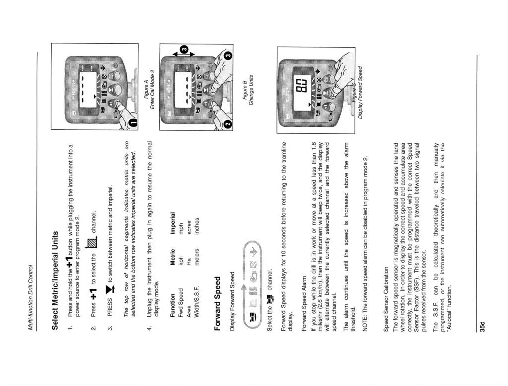
37 Tramlining The meter can automatically leave tractor track marks or tramlines in the correct position for subsequent accurate bout matching of spraying and fertilizing applications. The system operates by stopping the drive to 2 + 2feed rollers (two in the left side of the hopper for the left track mark and two in the right side of the hopper for the right track mark) as factory fitted, these will give a tramline track width of 3 times the drill row spacing. Refer to Figure 56 Drive to the two feed rollers at the left end of each half of the meter assembly is disengaged by arms attached to an electric actuator. These feed rollers are marked with tractor tread decals on the back of the meter assembly. Drive is automatically engaged/disengaged in the required sequence by the monitor control box positioned in the cab. A magnet and sensor on the contact drive record the bout count. See separate monitor instruction section for further information and programming instruction. Setting up for Tramlines The drill is set up to do symmetrical tramlining for 18m (60 ft) applicator booms, or asymmetrical right tramlining for 12m (40 ft) and 24m (80 ft) applicator booms. See Tramlining instructions in the Monitor section of this manual. With the optional NTA2000 dual tramline controls kit, (Great Plains P/N C) the drill can be set up for 10 bout tramlining for 15m (50 ft) applicator booms or 18 bout tramlining for 27m (90 ft) applicator booms. Any seed hose can be connected to the tramline marked feed rolls on the air distribution chamber. For symmetrical tramlining, connect the right tramline marked feed rolls to the desired two rows right of center to leave a mark for the right sprayer track, and connect the left tramline marked feed rolls to the desired two rows left of center to leave a mark for the left sprayer track Asymmetrical Right Tramlining Asymmetrical right tramlining only requires the use of the right tramline marked feed rolls. The actuator arm to the left tramline marked feed rolls must be disconnected. For asymmetrical right tramlining connect the right tramline marked feed rolls to the desired two rows at the right end of the drill to leave a mark for the sprayer tracks on two consecutive passes. Refer to Figure 57 Disconnect the actuator arm at the left side of the meter assembly that operates the left feed roll tramline clutch. This arm will have to be tied over to the right so the star shaped teeth on the arm do not slide over and contact the feed roll clutch spring. Note: With the optional NTA2000 dual tramline controls kit, (Great Plains P/N C) it will not be necessary to disconnect the actuator arm. Figure 56 Tractor Tread Decal Figure 57 Actuator Arm /2/2006 NTA M 35

38
39
40
41
42
43
44
45
46
47
48
49
50
51
52

53
54
55
56
57
58 Troubleshooting Problem Drill raising and lowering rough and uneven Coulters not going deep enough Drill not tracking behind coulters Openers plugging in no-till conditions Drill Seeding too deep Uneven seed spacing or uneven stand Opener disks not turning freely Solution Check for air trapped in hydraulic lines or cylinders. Bleed hydraulics if necessary. Refer to Bleeding the Hydraulic Systems, Preparation and Setup, page 11. Retract tongue cylinder. Add weight to hitch frame. Refer to Coulter Down Pressure, Adjustments, Page 25. Too much weight is being used by openers; set drill openers to lightest spring setting. Refer to Opener Down Pressure, Adjustments, page 27. Shorten coulter springs to increase down pressure. Refer to Coulter Springs, Adjustments, Page 25. Lower Coulters on Frame. Refer to Coulter Depth, Adjustments,, page 23. Check if coulters are aligned with openers. Check if leaf spring is out of alignment. Refer to Leaf Spring Adjustment, Adjustments, page 27. Drill across standing residue. Change the press-wheel setting. Refer to Opener Depth, Adjustments, page 26. Remove weight from hitch. Check for plugging in the metering wheel. Check to be sure feed flaps are set evenly.refer to Feed Flaps, Meter, page 31. Check if seed tubes are plugged. Reduce ground speed. Check that opener disks turn freely. Increase opener down pressure so opener disks penetrate. Refer to Opener Down Pressure, Adjustments, page 27. Check for trash or mud build-up on optional Seed-Lok wheels. Check for trash or mud build-up on disk scrapers. Readjust scrapers. Refer to Disk Scraper Adjustment, Adjustments, page 28. Check if scrapers are too tight, restricting disk movement. Refer to Disk Scraper Adjustment, Adjustments, page 28. Check disk bearings. Check opener frame for possible damage. Check if opener disks turn freely by hand but not in field. If so, reduce down pressure on openers. Refer to Opener Down Pressure, Adjustments, page 28. Check press-wheel adjustment for seeding depth. Refer to Opener Depth, Adjustments, page 26. Actual seeding rate Check seed-rate setting. Seed Rate Charts, page 44. is different than desired Excessive seed cracking Uneven seeding depth Check air pressure in contact tire Refer to Tire Inflation Chart, Appendix, page 49. Position feed flap handle to a lower notch. Check that openers have sufficient down pressure. Refer to Opener Down Pressure, Adjustments, page NTA M 2/2/2006
59 Problem Press wheel not compacting soil as desired Press wheels or openers plugging Solution Reset press-wheel depth. Refer to Opener Depth, Adjustments, page 27. Increase down pressure on openers. Refer to Opener Down Pressure, Adjustments, page 28. Consider field conditions. Drilling in damp or wet conditions may increase this problem. Reduce down pressure on openers. Refer to Opener Down Pressure, Adjustments, page 28. Do not back up or stop and allow drill to roll back with openers in ground. Check optional Seed-Lok wheels. 2/2/2006 NTA M 37
60 Maintenance and Lubrication Proper servicing and adjustment are key to long life of any farm implement. With careful and systematic inspection you can avoid costly maintenance, time and repair. Always turn off and remove tractor key before making any adjustments or performing any maintenance.! WARNING! You may be severely injured or killed by being crushed by the falling implement. Always have transport locks in place and frame sufficiently blocked up when working on implement.! WARNING! Escaping fluid under pressure can have sufficient pressure to penetrate the skin. Check all hydraulic lines and fittings before applying pressure. Fluid escaping from a very small hole can be almost invisible. Use paper or cardboard, not body parts, and wear heavy gloves to check for suspected leaks. If injured, seek medical assistance from a doctor that is familiar with this type of injury. Foreign fluids in the tissue must be surgically removed within a few hours or gangrene will result. 1. After using implement for several hours, check all bolts to be sure they are tight. 2. Inflate tires as specified on Tire Inflation Chart, Appendix, page Replace any worn, damaged or illegible safety decals. Obtain new decals from your Great Plains dealer. Refer to Safety Decals, Important Safety Information, page 4 for decal placement. 4. Check drill drive chains for wear. Replace if necessary. Adjust idlers to remove excess slack from chains. Storage Store implement where children do not play. If possible, store inside for longer implement life. 1. Clean implement as necessary. Be sure seed boxes are cleaned completely before storing. 2. Lubricate all fittings as indicated under Lubrication, Maintenance and Lubrication, page 38. When in storage, lower openers on a board or hard surface. Apply a light coat of oil to exposed cylinder rods. 38 NTA M 2/2/2006
61 Lubrication Lubrication Legend Multipurpose spray lube Multipurpose grease lube Multipurpose oil lube 50 Intervals at which lubrication is required Vertical Pivot Bushings, Top and Bottom Two zerks on back of vertical-pivot tube on transport frame one above and one below frame Lubricant = Grease Quantity = Until grease begins to emerge 10 Coulter Swing Arm Pivot Located on top of each coulter casting Lubricant = Grease Quantity = Until grease begins to emerge Seasonally Coulter Hub Bearings Located on each coulter hub Lubricant = Grease Quantity = Force grease into tapered roller bearings, but do not pressurize cavity enough to blow out seal or hub cap 2/2/2006 NTA M 39


62 Tongue to Main Frame Pivot Located at rear of tongue Lubricant = Grease Quantity = Until grease begins to emerge As Required Drive Chains Lubricant = Chain Lube Quantity = Spray Thoroughly Opener Wing Fold Pivot Two zerks, one on each opener wing fold pivot point Lubricant = Grease Quantity = Until grease begins to emerge NTA M 2/2/2006
63 Seasonally Transport Wheel Bearings Lubricant = Grease Quantity = Repack bearings and check seals 10 Optional Folding Markers Six zerks, three on each marker Lubricant = Grease Quantity = Until grease begins to emerge Seasonally Optional Folding Markers Lubricant = Grease Quantity = Repack bearings 2/2/2006 NTA M 41

64 10 Gauge Wheel Pivot Bearings Three zerks, one on each end of pivot and one in the middle Lubricant = Grease Quantity = Until grease begins to emerge Auger Arm Pivot Bearings Three zerks, one on the auger arm 1st section pivot, one on the auger arm 2nd section pivot and one on the auger swivel pivot Lubricant = Grease Quantity = Until grease begins to emerge NTA M 2/2/2006
! CAUTION! ! WARNING! General Information
 Great Plains Mfg., Inc. Installation Instructions Used with: 2SF24, 24-Foot Two-Section Drill General Information Two-Section, Hydraulic Folding Marker 2SF30, 30-Foot Two-Section Drill 2SBM30, 30-Foot
General Information. NTA607HD Lift Assist Adjustments. Tools Required. Work Location. Notations and Conventions U B F D R B F L
 Great Plains Manufacturing, Inc. 1 NTA607HD Lift Assist Adjustments Null4: When you see this symbol, the subsequent instructions and warnings are serious - follow without exception. Your life and the lives
General Information. Installation Instructions. CP1000 & FCP1000 Folding Markers. Used with: CP1000 FCP1000
 Installation Instructions CP1000 & FCP1000 Folding Markers Used with: CP1000 FCP1000! When you see this symbol, the subsequent instructions and warnings are serious - follow without exception. Your life
CULTIVATOR SAFETY SECTION
 CULTIVATOR SAFETY SECTION The above safety-alert symbol means ATTENTION! Be Alert! Your personal safety is involved This symbol draws your attention to important instructions concerning your personal safety.
1. SAFETY 2. PREPARATION 3. FRAME 4. TRANSMISSION 5. DRIVE 6. ROW UNIT 7. OPTIONAL EQUIPMENT
 TABLE OF CONTENTS 1. SAFETY 2. PREPARATION 3. FRAME 4. TRANSMISSION 5. DRIVE 6. ROW UNIT 7. OPTIONAL EQUIPMENT This symbol means: ATTENTION - BECOME ALERT YOUR SAFETY IS INVOLVED. When you see this symbol
Operator s Manual. Manufacturing, Inc. Foam Marker. Serial Number S1347 and Above
 Operator s Manual Serial Number S1347 and Above Manufacturing, Inc.! Read the operator s manual entirely. When you see this symbol, the subsequent instructions and warnings are serious - follow without
Tube-Line Accelerator Spinner Kit
 Tube-Line Accelerator Spinner Kit Operator's Manual PP-00799 (19/09/11) 2 TO THE OWNER This manual contains information concerning the adjustment, assembly and maintenance of your Tube-Line Spinner Kit.
OPERATOR S MANUAL AND PARTS LISTING FOR THE. STM Mounted Harrow
 MANUFACTURERS OF QUALITY AGRICULTURAL EQUIPMENT SINCE 1936 OPERATOR S MANUAL AND PARTS LISTING FOR THE STM Mounted Harrow With FH 5-Bar Section VERSION: 10-07AJF TO THE OWNER AND OPERATORS Before assembling
OPERATOR S MANUAL AND PARTS LISTING FOR THE. CTM Series Mounted Harrow
 MANUFACTURERS OF QUALITY AGRICULTURAL EQUIPMENT SINCE 1936 OPERATOR S MANUAL AND PARTS LISTING FOR THE CTM Series Mounted Harrow VERSION: 7-12 (MM-2300) TO THE OWNER AND OPERATORS Before assembling or
310 SERIES TILT-TO-LOAD ROTATOR. The Specialist In Drum Handling Equipment
 OPERATOR S MANUAL FOR MORSE TILT-TO-LOAD DRUM ROTATOR SAFETY INFORMATION: While Morse Manufacturing Co. drum handling equipment is engineered for safety and efficiency, a high degree of responsibility
Classic Aire Series Vacuum Plot Planter. Operators Manual
 Classic Aire Series Vacuum Plot Planter Operators Manual i Operator s Manual Seed Research Equipment Solutions 210 East 10 th Ave Hutchinson, KS 67501 Phone 1-877-357-7737 Fax 1-620-728-1270 For technical
20 Ton SD Shop Press Operating Instructions
 20 Ton SD Shop Press Operating Instructions MODEL NO. 850SD Hazard Symbols Used in the Manuals This manual includes the hazard symbols defined below when the operations or maintenance job involves a potential
30T A/Manual Hydraulic Shop Press
 30T A/Manual Hydraulic Shop Press Operation Manual 1 1. Important Information 1.1 Safety Information 1.1.1 Hazard Symbols Used in the Manuals This manual includes the hazard symbols defined below when
75 Ton SD Shop Press Operating Instructions
 75 Ton SD Shop Press Operating Instructions MODEL NO. 856SD Hazard Symbols Used in the Manuals This manual includes the hazard symbols defined below when the operations or maintenance job involves a potential
Operator s/parts Manual
 Operator s/parts Manual 24 & 30 Folding No-Till Drill Harrow Manufacturing, Inc. P.O. Box 5060 Salina, Kansas 67402-5060! Read the Operator s manual entirely. When you see this symbol, the subsequent instructions
Installation and Service Manual
 An Actuant Company Installation and Service Manual Heavy Duty Hydraulic Stabilization Legs CONTENTS Part # 3010003129 REV 0D Section Page 1.0 Receiving Instructions 2 2.0 Safety Issues 2 3.0 Hydraulic
HYDRAULIC PUNCH DRIVER 38456, 38520, 7306 / 7306SB, 7310 / 7310SB, 7506, 7606SB, 7610SB, 7625 / 7625Pg / 7625PgSB, 7646 / 7646Pg / 7646PgSB
 INSTRUCTION MANUAL HYDRAULIC PUNCH DRIVER 38456, 38520, 7306 / 7306SB, 7310 / 7310SB, 7506, 7606SB, 7610SB, 7625 / 7625Pg / 7625PgSB, 7646 / 7646Pg / 7646PgSB Read and understand all of the instructions
HYDRAULIC WINCH FOR AUGERS UP TO WR10 X 71 / W130 X 41 ASSEMBLY & OPERATION MANUAL
 HYDRAULIC WINCH ASSEMBLY & OPERATION MANUAL Read this manual before using product. Failure to follow instructions and safety precautions can result in serious injury, death, or property damage. Keep manual
Parts & Operators Manual
 Parts & Operators Manual (888) 317-5878 www.talet.ca To The Owner General Comments Congratulations on the purchase of your new Talet Mat Grapple. Your unit was carefully designed and manufactured to give
Concept 2000 Tillage OPERATOR S. Manual C
 Concept 2000 Tillage OPERATOR S Manual C26314-08 Table of Contents Section 1: Safety... 1-1 Signal Words... 1-2 General Operation... 1-3 Tractor Operation... 1-3 Chemicals... 1-4 Transporting... 1-5 Hydraulics...
DRILL MAINTENANCE ADJUSTMENTS BEFORE GOING TO THE FIELD
 FOLDING NO-TILL Air DRILL 3N-4010HDA 3-SECTION DRILL MAINTENANCE Proper servicing and adjustment is key to the long life of all farm equipment. With careful and systematic inspection of your grain drill,
DK ton, Double-acting, Die-type Crimping Tool
 INSTRUCTION MANUAL DK6040 60-ton, Double-acting, Die-type Crimping Tool Read and understand all of the instructions and safety information in this manual before operating or servicing this tool. Register
KRAC KC-600 PLOW OPERATOR S MANUAL
 PLOW OPERATOR S MANUAL RWF INDUSTRIES 873 Devonshire Ave., Woodstock, Ontario N4S 8Z4 Tel: (519) 421-0036 Toll Free: 1-800-263-1060 Fax: (519) 421-0028 Email: parts@rwfbron.com JANUARY 2015 THE INFORMATION
MODEL SWH10 1,000 LB CAPACITY SWIVEL HOIST
 MODEL SWH10 1,000 LB CAPACITY SWIVEL HOIST PARTS BREAKDOWN AND OPERATING MANUAL Copyright 2007, Arcan Professional Tools Rev: 05/15/07 This operating manual contains important safety information. Read
H4802, H4802-1, H , and Pole Tampers
 SERVICE MANUAL H4802, H4802-1, H-4802-6, and 43227 Pole Tampers Serial Codes FKA, FKF, FKM, FZP, FZR, FZT, and FZV Read and understand all of the instructions and safety information in this manual before
44in Side Discharge Mower for Wheel Horse XL 440H Lawn Tractors Model No Serial No and Up
 Form No. 5-8 in Side Discharge Mower for Wheel Horse XL 0H Lawn Tractors Model No. 790 Serial No. 5000000 and Up Operator s Manual Register your product at www.toro.com Original Instructions (EN) Contents
MUELLER. Mega-Lite Drilling Machine. Reliable Connections. table of contents PAGE. Equipment 2. Operating Instructions 3-4. Parts Information 5
 operating Instructions manual MUELLER Mega-Lite Drilling Machine table of contents PAGE Equipment 2 Operating Instructions 3-4 Parts Information 5 Travel Charts 6-11! WARNING: 1. Read and follow instructions
LITERIDER 2&3 IMPORTANT WARNING. 2Bike (1x) Bolt (1x) Nut (1x) Small Hex Wrench (1x)
 Bolt (1x) Nut (1x) Small Hex Wrench (1x)") LITERIDER 2&3 3 Bike (1x) Bolt (1x) Flat Washer (2x) Nut (1x) Large Hex Wrench (1x) 2Bike (1x) wrench (1x) Small Hex Wrench (1x) keys (2x) Long Strap (1x) 2-Zip Strips (6x) 3-Zip Strips (9x) Wheel strap
LITERIDER 2&3 3 Bike (1x) Bolt (1x) Flat Washer (2x) Nut (1x) Large Hex Wrench (1x) 2Bike (1x) wrench (1x) Small Hex Wrench (1x) keys (2x) Long Strap (1x) 2-Zip Strips (6x) 3-Zip Strips (9x) Wheel strap
SIGNATURE DEF REELS Models: Bare Reel Reel Reel Reel
 SERVICE BULLETIN SB2023 Rev C 7/11 SIGNATURE DEF REELS Models: 2400-006 Bare Reel 2400-007 16 Reel 2400-008 20 Reel 2400-009 30 Reel Thoroughly read and understand this manual before installing, operating
INSTALLATION, OPERATION AND SERVICE MANUAL ABS AIR BAG LIFT
 INSTALLATION, OPERATION AND SERVICE MANUAL ABS AIR BAG LIFT P.O. Box 1058 1058 West Industrial Avenue Guthrie, OK 73044-1058 405-282-5200 FAX: 405-282-8105 www.autoquip.com Item # 830ABS Version 1.0 07/2001
35 TON HYDRAULIC PUNCH WARNING
 OPERATORS GUIDE REL-35T-PNC 35 TON HYDRAULIC PUNCH NOTICE Sizes, weights and tool specifications listed in this manual are subject to change without notice. Please consult factory for information and updates.
Specifications Testing & Adjusting Disassembly & Assembly
 SB4191E00 Jul. 2005 Specifications Testing & Adjusting Supplement for Quad Lift Mast D20/25/30/32/33S-3 G/GC20/25/30/32P-3 G/GC20/25/30/32E-3 Important Safety Information Most accidents involving product
AC1810 / AC1810-A TECHNICAL SPECIFICATIONS. Operating Pressure psi ( kgs/cm²) [AC1810] Displacement. Net Weight
![AC1810 / AC1810-A TECHNICAL SPECIFICATIONS. Operating Pressure psi ( kgs/cm²) [AC1810] Displacement. Net Weight](/thumbs/83/88369739.jpg "AC1810 / AC1810-A TECHNICAL SPECIFICATIONS. Operating Pressure psi ( kgs/cm²) [AC1810] Displacement. Net Weight") Technical Specifications Operating Instructions Maintenance Information Troubleshooting Guide Parts Diagrams AC1810 / AC1810-A THE EVOLUTION OF PERFECTION CAUTION: Before attempting to use or service this
Technical Specifications Operating Instructions Maintenance Information Troubleshooting Guide Parts Diagrams AC1810 / AC1810-A THE EVOLUTION OF PERFECTION CAUTION: Before attempting to use or service this
TN548 TRENCHER OPERATOR S MANUAL
 TN548 TRENCHER OPERATOR S MANUAL DEC 2014 T A B L E O F C O N T E N T S S E C T I O N D E S C R I P T I O N P A G E 1 Introduction................... 1 1.1 Overview................... 1 1.2 Intended Use
REL-510H WARNING NOTICE 12 TON SINGLE ACTING REMOTE HYDRAULIC CRIMPING HEAD
 OPERATORS ORS GUIDE REL-510H 12 TON SINGLE ACTING REMOTE HYDRAULIC CRIMPING HEAD Compatible with U style and RELIABLE R12 shell type 12 ton compression dies. RELIABLE EQUIPMENT & SERVICE CO., INC. 92 Steamwhistle
OPERATOR S MANUAL SPREADER. CSS, VNQ [For Combine Harvester AW82V] Original instructions
![OPERATOR S MANUAL SPREADER. CSS, VNQ [For Combine Harvester AW82V] Original instructions](/thumbs/90/102423265.jpg "OPERATOR S MANUAL SPREADER. CSS, VNQ [For Combine Harvester AW82V] Original instructions") OPERATOR S MANUAL SPREADER CSS, VNQ [For Combine Harvester AW82V] en Original instructions Introduction Introduction Please read this operator s manual before using your spreader. We would first like to
OPERATOR S MANUAL SPREADER CSS, VNQ [For Combine Harvester AW82V] en Original instructions Introduction Introduction Please read this operator s manual before using your spreader. We would first like to
Assembly Drawing: W-311B-A01, or as applicable Parts List: W-311B-A01-1, or as applicable Special Tools: , , &
 REDQ Regulators Model 411B Barstock Design Powreactor Dome Regulator OPERATION AND MAINTENANCE Contents Scope..............................1 Installation..........................1 General Description....................1
SERIES 2 RAMP OWNER S MANUAL TOOLS REQUIRED: BEFORE YOU BEGIN... Read and understand these instructions before beginning a ramp setup.
 SERIES 2 RAMP OWNER S MANUAL BEFORE YOU BEGIN... Read and understand these instructions before beginning a ramp setup. Use caution and care for your back when lifting, pushing, pulling, folding or unfolding
PDY TON HYDRAULIC CRIMPING TOOL WARNING
 OPERATORS ORS GUIDE PDY-1220 12 TON HYDRAULIC CRIMPING TOOL All information found in this guide must be read and understood before use or testing of this tool. Failure to read and understand these warnings
MUELLER GAS. No-Blo Operations Using D-5. Drilling Machine. Reliable Connections. General Information 2
 operating Instructions manual MUELLER GAS TAble of contents PAGE No-Blo Operations Using D-5 General Information 2 Installing No-Blo Service Tees, Service Stop Tees and Curb Stop Tees 3-8 Reconditioning
Vac Bagger Wheelhorse 42 and 48 Mowers for Classic Garden Tractors
 Form No. -80 Vac Bagger Wheelhorse and 8 Mowers for Classic Garden Tractors Model No. 790 000000 & Up Operator s Manual Domestic English (EN) Contents Page Introduction................................
Installation, Operation & Maintenance Manual for Flo-Max Coupler Bracket Model FM150
 Installation, Operation & Maintenance Manual for Flo-Max Coupler Bracket Model FM150 January 2013 Form FVC 084 - Rev 02 IMPORTANT: KEEP THIS DOCUMENT WITH THE PRODUCT UNTIL IT REACHES THE END USER. 1.
Operation Manual Guillotine Cutter RC-5
 Operation Manual Guillotine Cutter RC-5 Technical Specifications General Safety/Operating Instructions Using the Guillotine Cutter/Crimper Blade Change Instructions Maintenance Instructions This is a detailed
ModelsEZU-15 & EZU-15-R. BISHAMON INDUSTRIES CORPORATION 5651 East Francis Street Ontario, California 91761, USA (909) (800)
 (800)") UP P n e u m a t i c ModelsEZU-15 & EZU-15-R BISHAMON INDUSTRIES CORPORATION 5651 East Francis Street Ontario, California 91761, USA (909) 390-0055 (800) 231-3187 Table of Contents GETTING STARTED......................................
UP P n e u m a t i c ModelsEZU-15 & EZU-15-R BISHAMON INDUSTRIES CORPORATION 5651 East Francis Street Ontario, California 91761, USA (909) 390-0055 (800) 231-3187 Table of Contents GETTING STARTED......................................
MODEL 840 AIR HYDRAULIC PUMP INSTRUCTION
 MODEL 840 AIR HYDRAULIC PUMP INSTRUCTION Jackco Transnational Inc. 202 South El Monte, CA 888-452-2526 www.jackco.com FOR YOUR SAFETY Read all instructions, warnings and cautions carefully. Follow all
INSTALLATION INSTRUCTIONS FOR ROLLOVER PROTECTION SYSTEM (ROPS)
") INSTALLATION INSTRUCTIONS FOR ROLLOVER PROTECTION SYSTEM (ROPS) This manual contains assembly, operating, maintenance and safety instructions for your ROPS. Before Installing the ROPS or operating a machine
INSTALLATION INSTRUCTIONS FOR ROLLOVER PROTECTION SYSTEM (ROPS) This manual contains assembly, operating, maintenance and safety instructions for your ROPS. Before Installing the ROPS or operating a machine
REL-46 WARNING NOTICE 15 TON SINGLE ACTING REMOTE HYDRAULIC CRIMPING HEAD. Compatible with RELIABLE R15 and P Style dies. REL-46 Manual
 OPERATORS ORS GUIDE REL-46 15 TON SINGLE ACTING REMOTE HYDRAULIC CRIMPING HEAD Compatible with RELIABLE R15 and P Style dies. RELIABLE EQUIPMENT & SERVICE CO., INC. 301 Ivyland Road Warminster, PA 18974
AIR/OVER HYDRAULIC JACK 20 TON
 AIR/OVER HYDRAULIC JACK 0 TON 4487 ASSEMBLY AND OPERATING INSTRUCTIONS 349 Mission Oaks Blvd., Camarillo, CA 930 Visit our Web site at http://www.harborfreight.com Copyright 999 by Harbor Freight Tools.
OPERATORS MANUAL MODEL 365 BACK LAPPING MACHINE WARNING
 MODEL 365 BACK LAPPING MACHINE OPERATORS MANUAL WARNING You must thoroughly read and understand this manual before operating the equipment, paying particular attention to the Warning & Safety instructions.
HPB25 Hydraulic Paving Breaker
 INSTRUCTION MANUAL HPB25 Hydraulic Paving Breaker Read and understand all of the instructions and safety information in this manual before operating or servicing this tool. Register this product at www.greenlee.com
DRAG HARROW SAFETY & OPERATING INSTRUCTIONS. Original Language. Serial No. Order No.
 DR ` DRAG HARROW SAFETY & OPERATING INSTRUCTIONS Serial No. Order No. Original Language DR Power Equipment Toll-free phone: 1-800-DR-OWNER (376-9637) Fax: 1-802-877-1213 Website: www.drpower.com Read and
VIBRO-flex & VIBRO-till OWNERS MANUAL Operating Guide. Kongskilde VF6000 VT 2800
 VIBRO-flex 6000 & VIBRO-till 2800 Kongskilde VF6000 VT 2800 OWNERS MANUAL Operating Guide *Model may not be exactly as shown. Kongskilde reserves the right to make changes to product designs and specifications
Steel Spring Driven Reel Instruction Manual
 Steel Spring Driven Reel Instruction Manual WARNING: Read carefully and understand all INSTRUCTIONS before operating. Failure to follow the safety rules and other basic safety precautions may result in
Hydraulic Punch Drivers
 INSTRUCTION MANUAL 7804SB / 7806SB Quick Draw 7704SB / 7706SB Quick Draw Flex 7904SB / 7906SB Quick Draw 90 Quick Draw Hydraulic Punch Drivers Serial Codes AHJ, YZ, and ZA Read and understand all of the
SPECIFICATIONS Type: Twin stack, single phase Tank: 4 gallon Air Output: PSI; PSI Max PSI: 125 PSI HP: 1.
 2 GALLON TWIN STACK AIR COMPRESSOR Model: 9526 DO NOT RETURN TO STORE. Please CALL 800-348-5004 for parts and service. CALIFORNIA PROPOSITION 65 WARNING: You can create dust when you cut, sand, drill or
Operating Instructions for BAIR22-6 AIR-POWERED CRIMPING TOOL
 Operating Instructions for BAIR22-6 AIR-POWERED CRIMPING TOOL Read and understand all of the instructions and safety information in this manual before operating or servicing this tool. Table of Contents
Tru Trak Sulky Proline Mid Size Mower Attachment
 Form No. -7 Tru Trak Sulky Proline Mid Size Mower Attachment Model No. 00 000000 and Up Operator s Manual Domestic English (EN) Contents Page Introduction................................ Safety.....................................
DBML-60/80 Squeeze Tool
 DBML-60/80 Squeeze Tool OPERATORS MANUAL Description The Mustang Model DBML-60/80 Hydraulic squeeze tool has been manufactured since 1995. A Mustang 3 3/4 bore doubleacting cylinder producing 41,000 lbs
This section provides general information and recommendations required prior to installing, operating or maintaining your KAT Master Hitch.
 WBM Parts and Installation Manual for KAT Master Hitch General Information This section provides general information and recommendations required prior to installing, operating or maintaining your KAT
MANURE SPREADER OPERATION AND ASSEMBLY MANUAL
 MANURE SPREADER OPERATION AND ASSEMBLY MANUAL INTRODUCTION TO THE OWNER: Read this manual before operating your equipment. Keep this manual handy for ready reference. Require all operators to read this
BUTTERFLY VALVES Series 800
 BUTTERFLY VALVES Series 800 WARNING Before proceeding read ALL instructions and become familiar with the equipment and associated drawings. Follow ALL applicable safety regulations and codes for pressurized
VERSA BIKE RACK INSTRUCTIONS
 VERSA BIKE RACK INSTRUCTIONS Models #8, 8 Important This rack is designed for use with a or. receiver hitch. The rack is designed to hold a maximum of two bicycles. Do not use it for anything other than
60 Drum Style Spike Aerator
 60 Drum Style Spike Aerator OWNER S MANUAL WARNING: Read carefully and understand all ASSEMBLY AND OPERATION INSTRUCTIONS before operating. Failure to follow the safety rules and other basic safety precautions
Pressure Relief Valve Instruction Manual
 CVR3-M0_062017 Pressure Relief Valve Instruction Manual MODEL: CVR3 SFA Companies 10939 N. Pomona Ave. Kansas City, MO 64153 Tel: 888-332-6419 * Fax: 816-448-2142 E-mail: sales@bvahydraulics.com Website:
Trilogy Theory of Operation
 INSTALLATION & OVERVIEW... 2 Load Height... 2 Approach Angle... 2 Footprint... 3 Protrusion... 3 Mounting the... 4 General Torque Specs... 4 OPERATION OF BIKE RACK... 5 Loading Bikes... 5 Unloading Bikes...
Instruction Manual. Maximum Operating Pressure 1,500 bar
 Hydraulic Bolt Tensioners Model DBT Series Maximum Operating Pressure 1,500 bar ABSOLUTE EQUIPMENT PTY LTD 2/186 Granite Street, GEEBUNG QLD 4034 Australia sales@absoluteequipment.com.au Phone: +61 7 3865
MAINTENANCE FOR THE MODEL 210B-2 SRA
 SAFETY PRECAUTIONS FOR THE System Under Pressure: Shut off air supply and disconnect air hose before disassembling or disconnecting parts. Flying Debris: During boring, chips may be ejected. Stay behind
Torque Specifications
 SENR3130-10 Torque Specifications All Caterpillar Products S/N From the library of Barrington Diesel Club CONTENT General Information 01/07/2005 Introduction to Torque 01/07/2005 Torque-Turn 01/07/2005
Repair instructions. Pivot bushing replacement. XL-AS10001RM-en-DE Rev B
 Repair instructions Pivot bushing replacement XL-AS10001RM-en-DE Rev B Table of contents Table of contents 1 General information... 3 1.1 Safety information...3 1.2 Legal information...4 1.3 Order and
Retractable Hose Reel with 3/8" x 50' PVC Hose
 Retractable Hose Reel with 3/8" x 50' PVC Hose Item# 4816153 Owner s Manual Assembly and Operation Instructions MADE IN CHINA Read carefully and understand all ASSEMBLY AND OPERATION INSTRUCTIONS before
Shoreline Cantilever Lift 2500lb Capacity Models: (108" inside width) - Part # (120" inside width) - Part #
 - Part # (120 inside width) - Part #") Shoreline Cantilever Lift 2500lb Capacity Models: 25108 (108" inside width) - Part # 1017402 25120 (120" inside width) - Part # 1017403 1. 2. 3. 4. 5. CAUTION - PUT SAFETY FIRST Before attempting to install
Shoreline Cantilever Lift 2500lb Capacity Models: 25108 (108" inside width) - Part # 1017402 25120 (120" inside width) - Part # 1017403 1. 2. 3. 4. 5. CAUTION - PUT SAFETY FIRST Before attempting to install
Tire Inflation Cage Kit For servicing only single piece automotive, and most light truck tire/wheel assemblies
 Tire Inflation Cage Kit 85608214 For servicing only single piece automotive, and most light truck tire/wheel assemblies This is a supplement to your operating manual and covers the setup and use of the
Pressure Dump Valve Service Kit for Series 2300 Units
 Instruction Sheet Pressure Dump Valve Service Kit for Series 00 Units. Overview The Nordson pressure dump valve is used to relieve hydraulic pressure instantly in Series 00 applicator tanks when the unit
1 DRIVE INDUSTRIAL IMPACT WRENCH
 1 DRIVE INDUSTRIAL IMPACT WRENCH 92622 ASSEMBLY AND OPERATING INSTRUCTIONS 3491 Mission Oaks Blvd., Camarillo, CA 93011 Visit our Web site at http://www.harborfreight.com Copyright 2004 by Harbor Freight
Fiber Cable Puller with Tuf-Lugger lite
 7 OPERATING INSTRUCTION MANUAL Fiber Cable Puller with Tuf-Lugger lite Copyright 2015 DCD Design & Manufacturing Ltd. Revision 1.0 IMPORTANT SAFETY INSTRUCTIONS READ ALL INSTRUCTIONS BEFORE USING The Fiber
U.S. Patent No. 7,922,246. Patents Pending
 U.S. Patent No. 7,922,246 Patents Pending 2 Table of Contents Page General Information... 3 Warnings and Cautions... 4 Tools... 6 SmartDock Parts... 6 Initial Set-Up and Adjustment... 7 Select Valve Retaining
Hydraulic Punch Drivers
 SERVICE MANUAL 7804SB / 7806SB Quick Draw 7704SB / 7706SB Quick Draw Flex Quick Draw Hydraulic Punch Drivers Serial Codes AHJ and YZ Read and understand all of the instructions and safety information in
BRUSH CUTT CXC550 CUTTER
 BRUSH CUTT CXC550 CUTTER OPERATOR S MANUAL Issue Date: April 2017 TABLE OF CONTENTS 1 INTRODUCTION... 1 1.1 Overview... 1 1.2 Intended Use And Foreseeable Misuse... 1 2 SAFETY... 2 2.1 Safety Alert Symbol
EZee Glider Manual. Tools needed for Assembly: Wrench (included) Philips Screwdriver (not included) Assembly Instructions
 Philips Screwdriver (not included) Assembly Instructions") EZee Glider Manual Congratulations on your purchase of the EZee Glider! Your glider is designed for years of nearly carefree use by your child. These instructions include how to set up your glider and
EZee Glider Manual Congratulations on your purchase of the EZee Glider! Your glider is designed for years of nearly carefree use by your child. These instructions include how to set up your glider and
3/8" Dr. Air Butterfly Impact Wrench
 8192106 3/8" Dr. Air Butterfly Impact Wrench Owner s Manual Read and understand all instructions before use. Retain this manual for future reference. Specifications Construction: Polished aluminum and
Operator s Manual. with Maintenance Schedule. Fourth Edition Second Printing Part No
 Operator s Manual with Maintenance Schedule Fourth Edition Second Printing Part No. 82297 Operator s Manual Fourth Edition Second Printing Important Read, understand and obey these safety rules and operating
Paintball Marker. User s Manual. 530 South Springbrook Road Newberg, OR 97132
 Paintball Marker User s Manual 530 South Springbrook Road Newberg, OR 97132 Component Concepts, Inc., 530 South Springbrook Road, Newberg, OR 97132 Phone: (503) 554-8095 Fax: (503) 554-9370 www.phantomonline.com
Mini Glider Manual. Your Glider comes partially assembled. The front wheel and the handlebars require assembly.
 Mini Glider Manual Congratulations on your purchase of the Mini Glider! Your glider is designed for years of nearly carefree use by your child. These instructions include how to set up your glider and
SASK-A-POLE OWNERS AND USERS MANUAL
 SASK-A-POLE OWNERS AND USERS MANUAL GENERAL INFORMATION The Saskatchewan Abilities Council s Sask-a-Pole accessibility and transfer aid is designed to help provide safe and easy access to chairs, beds,
INSTALLATION COMMISSIONING, OPERATION & MAINTENANCE MANUAL
 WedgeRock RW Series Worm Gear Actuators INSTALLATION COMMISSIONING, OPERATION & MAINTENANCE MANUAL Revision 01 Date 4/3/17 Page 1 Table of Contents 1.0 INTRODUCTION... 4 1.1 PURPOSE... 4 1.2 AUDIENCE...
56 Bypass Mini Grapple
 56 Bypass Mini Grapple T-1001 1 INTRODUCTION Branch Manager Attachments would like you to be completely satisfied with your new product, so please contact us for help with service, replacement parts, or
2,500/4,000 LB Easy Riser Vertical Cable Feighner Lift
 2,500/4,000 LB Easy Riser Vertical Cable Feighner Lift CAUTION - PUT SAFETY FIRST 1. Before attempting to install or operate this lift, study and fully understand the proper operating procedures and safety
Wildcat LB Winch Kit. Operator s Manual Installation Instructions Replacement Parts List. With Wireless Control System.
 p/n 2259-560 Wildcat 4000 LB Winch Kit With Wireless Control System Operator s Manual Installation Instructions Replacement Parts List 2012 Arctic Cat Inc. Trademarks of Arctic Cat Inc. Thief River Falls,
Pressure Dump Valve Service Kit for Series 3000 Units
 Instruction Sheet Pressure Dump Valve Service Kit for Series 000 Units. Overview The Nordson pressure dump valve is used to relieve hydraulic pressure instantly in Series 00, 400, 500, and 700 applicator
170-CG Feed Unit SPONGE-JET USER MANUAL. Sponge-Jet, Inc. (USA) 14 Patterson Lane Newington, NH
 14 Patterson Lane Newington, NH") SPONGE-JET 170-CG Feed Unit USER MANUAL Sponge-Jet, Inc. (USA) 14 Patterson Lane +1-603-610-7950 Newington, NH 03801 www.spongejet.com AUGUST 2014, Sponge-Jet 170-CG User Manual - REV A / DOC: M-MKTG-002ENG
SPONGE-JET 170-CG Feed Unit USER MANUAL Sponge-Jet, Inc. (USA) 14 Patterson Lane +1-603-610-7950 Newington, NH 03801 www.spongejet.com AUGUST 2014, Sponge-Jet 170-CG User Manual - REV A / DOC: M-MKTG-002ENG
RIDE Inc. Rigscape Drilling Rig Procedures
 2016 RIDE Inc. Rigscape Drilling Rig Procedures Special Instructions/Conditions of Use Reading user procedure manual prior to use is essential Only persons that have been deemed competent in the operation
WBM Installation Manual KAT Master Hitch
 WBM Installation Manual KAT Master Hitch General Information This section provides general information and recommendations required prior to installing, operating or maintaining your KAT Master Hitch.
USER S MANUAL QUESTIONS? CAUTION. Model No. FMEX Serial No. Write the serial number in the space above for reference. Serial Number Decal
 Model No. FMEX81110.0 Serial No. Write the serial number in the space above for reference. USER S MANUAL Serial Number Decal QUESTIONS? If you have questions, or if parts are damaged or missing, please
OPERATIONS/PARTS MANUAL FOR PATTERSON'S WWP75H-10 HYDRAULIC WINCH.
 W. W. Patterson Company 3 Riversea Road Pittsburgh, PA 15233 Phone: 800-322-2018 FAX: 412-322-2785 OPERATIONS/PARTS MANUAL FOR PATTERSON'S WWP75H-10 HYDRAULIC WINCH. Please fill in the following blanks
WARNING: READ THE GENERAL INFORMATION MANUAL INCLUDED FOR OPERATING AND SAFETY PRECAUTIONS AND OTHER IMPORTANT INFORMATION.
 GSR500 Ram Assembly General Description The GSR500 single post lift / ram uses a 3-1/4 air powered cylinder, which is welded to a heavy gauge base. It is normally used to raise and lower a fluid handling
RASP RX3 Feed UnitTM SPONGE-JET USER MANUAL. Sponge-Jet, Inc. (USA) 14 Patterson Lane Newington, NH
 14 Patterson Lane Newington, NH") SPONGE-JET RASP RX3 Feed UnitTM USER MANUAL Sponge-Jet, Inc. (USA) 14 Patterson Lane +1-603-610-7950 Newington, NH 03801 www.spongejet.com Sponge-Jet RASP RX3 User Manual - REV A / DOC: MKT-014-ENG SPONGE-JET
SPONGE-JET RASP RX3 Feed UnitTM USER MANUAL Sponge-Jet, Inc. (USA) 14 Patterson Lane +1-603-610-7950 Newington, NH 03801 www.spongejet.com Sponge-Jet RASP RX3 User Manual - REV A / DOC: MKT-014-ENG SPONGE-JET
CP10K. 10,000 lb. Cable Puller Instruction Sheet. SAFETY ISSUES
 10,000 lb. Cable Puller Instruction Sheet CP10K SAFETY ISSUES IMPORTANT USER SAFETY AND PROTECTION: In setting up systems to fit your operations, care must be taken to select the proper components and
750 Cable Cutter INSTRUCTION MANUAL
 INSTRUCTION MANUAL 750 Cable Cutter Read and understand all of the instructions and safety information in this manual before operating or servicing this tool. Register this product at www.greenlee.com
DM-RD (English) Dealer s Manual. ROAD Rear Derailleur RD-9000 RD-6800 RD-5800 RD-4700
 Dealer s Manual. ROAD Rear Derailleur RD-9000 RD-6800 RD-5800 RD-4700") (English) DM-RD0003-09 ROAD Rear Derailleur Dealer s Manual RD-9000 RD-6800 RD-5800 RD-4700 CONTENTS IMPORTANT NOTICE...3 TO ENSURE SAFETY...4 LIST OF TOOLS TO BE USED...6 INSTALLATION...8 Chain length...
(English) DM-RD0003-09 ROAD Rear Derailleur Dealer s Manual RD-9000 RD-6800 RD-5800 RD-4700 CONTENTS IMPORTANT NOTICE...3 TO ENSURE SAFETY...4 LIST OF TOOLS TO BE USED...6 INSTALLATION...8 Chain length...
STAND AID 1600/ ECONOSTAND
 MAKERS OF STAND AID, POWER TOILET AID AND FREEDOM CHAIR STAND AID 600/ ECONOSTAND INSTRUCTIONS AND WARRANTY FOR STAND AID 600 STAND AID SERIAL # PO BOX 386 Sheldon, IA 50 (800) 83-8580 (7) 34-53 Fax: (7)