Risk Focus: Safe Bunker Operations. How to ensure safe bunkering practice to avoid spills
|
|
|
- Megan Wiggins
- 5 years ago
- Views:
Transcription

1 Risk Focus: Safe Bunker Operations How to ensure safe bunkering practice to avoid spills
2 CONTENTS How to ensure safe bunkering practice to avoid spills 3 Introduction 4 Why do bunker spills occur? 4 The human element 5 Bunkering fundamentals 5 Pre-arrival 7 Prior to bunkering 7 During bunkering 9 On completion 9 Summary Key points 10

3 How to ensure safe bunkering practice to avoid spills The Club s claim records indicate a recent increase in the number of pollution incidents relating to bunkering operations or internal bunker transfers, and even relatively minor incidents have resulted in very high value claims for the recovery of pollutants, clean-up, restoration operations and third party damages. Our experience suggests that in only a minority of cases do spills occur due to failure of the hoses or pipelines, which are required to be pressure tested on a periodic basis. Furthermore, the general standard of maintenance of shipboard deck bunker pipeline systems has much improved. The majority of bunker spills occur as a result of a tank overflowing. The oil is discharged from the tank air vent heads and flows into a containment box or save-all, which then overflows on to the deck. The oil accumulates on the deck and if a sufficient quantity is released, it may then spill over the raised guttering at the deck edge. Oil then flows down the ship s side and onto the water surface, which can then be distributed widely by river or sea currents, going on to oil port structures or other shore features and amenities. Although the vast majority of bunker transfers are performed without incident, very occasionally, things go wrong. This publication is aimed both at those serving on-board ship and on the bunkering barge. Risk Focus: Safe Bunker Operations 3

4 Introduction Bunkering operations are routine and yet critical, high risk operations which require to be carefully planned and performed by the crew in accordance with established shipboard procedures. Although the vast majority of bunker transfers are carried out without incident, very occasionally, things can and do go wrong. A loss of containment due to a tank overflow, or leakage from pipeline or transfer hose failure, may result in oil spilling overboard and polluting the marine environment. UK P&I Club claim records indicate that pollution incidents relating to bunkering operations or internal bunker transfers continue to occur with worrying frequency. Oil spills are bad news on a number of different levels, not least for their potential to inflict serious damage to marine ecosystems and particularly when involving viscous heavy fuel oils. Even relatively minor bunker spills may result in very high value claims for recovery of pollutants, clean up, restoration operations and third-party damages potentially running into seven figure dollar sums. In addition, shipowners and crews may also be exposed to heavy fines and criminal prosecution, with such incidents often being considered as strict liability offences irrespective of how the incident occurred. The UK Club s recent experience suggests that in only a minority of cases do bunker spills occur due to failure of the hoses or pipelines, whereas the majority of spills tend to be as a result of a tank overflowing. The oil is discharged from the bunker tank air vent head and flows into a containment save-all 1, which then overflows on to the deck and accumulates adjacent to the deck containment guttering at the ship s side. If a sufficient quantity of oil is released (or if insufficient preventative measures are in place) the oil may spill over the guttering at the deck edge, flow down the ship s side and onto the water surface with the potential to be widely distributed by river or sea currents. Apart from the immediate ecological impact to the marine environment, a spill may cause oiling damage to port structures, other vessels, natural shore features, flora, fauna, mariculture and leisure amenities. In the event of an incident, it is the responsibility of the crew to respond and to alert the relevant authorities to reduce the impact of the spillage on the surrounding environment. Why do bunker spills occur? Common causes of bunker spills can be summarised as follows. They should not necessarily be taken in isolation as causation may be due to a combination of factors: Improper set up of pipeline system valves Potentially causing either overpressure, or flow of bunkers to an unintended location. Insufficient monitoring of tank levels during bunkering All tanks, not only those nominated to receive the fuel. Excessive transfer rate or pressure Risk of exceeding the design pressure or capacity of the system; also increases operational stress on the crew. Air lock Depending on internal tank structure and the arrangement of ventilation pipework (exacerbated by excessive trim or list), an excessive pumping rate can cause pockets of air to become trapped in the tank. Release of the trapped air can cause a sudden unexpected discharge of mist or oil from the tank ventilator. This can cause a discharge before the tank is perceived to be full, catching operators unawares. 1 Even on vessels equipped with an overflow loop, the final overflow tank will vent externally to a similar containment arrangement. 4 Risk Focus: Safe Bunker Operations
5 Case study Bunker hose failure A vessel was bunkering HFO from a shore terminal via a layflat hose. On completion, residual HFO remained in the lines. In order to clear the lines, a compressed air-blow was agreed. The relevant tank valve was confirmed as open in readiness, and the Chief Engineer requested a supply of air at a low pressure. Flow through the pipeline was heard and the Chief Engineer requested an increase in the air pressure. During this increase, the hose failed at the connection to the vessel, spraying oil onto the surrounding deck area and into the sea. Scupper plugs were in-place, but there were no suitable containment measures fitted at the freeing ports, allowing contamination of the surrounding waters. Investigation findings The receiving vessel systems were found clear and in order, but there was some scope for HFO to remain in the lines. As the air pressure was increased, it is believed that the clamp connection in way of the layflat hose/flange was placed under fluctuating pressure loads, causing it to repeatedly flex and subsequently fail. Similar hoses found at the terminal were found to have some minor creases in way of the clamp connection. Storage of the layflat hoses was found to be such that it was possible to cause kinking of the hose at the clamped connections. Failure of the supplying hose does happen, whether as a result of poor maintenance or excessive pressure for operational reasons. There are a variety of hose types in use, such as the collapsible layflat used in this case, or reinforced spiral bound. Fuel transfer hoses should be resistant to abrasion and weathering. Where vulnerable, they should be suitably protected from impact damage. New hoses are pressuretested and certified, then should be re-tested to 1.5 x nominal pressure every 12 months and visually checked before every operation. Storage should not overstress the material. Limits are placed on the maximum bending radius, and some storage situations can exceed this limit, particularly at the connection. This also applies to layflat hoses where permanent kinking should be avoided. Receiving vessels should check the condition of delivery hoses themselves and, if in doubt, request the original test certificate and records of the last pressure test. Vessel freeing ports should be identified and confirmed as having adequate sealing arrangements, which should be fitted for the entire operation. Malfunction of valves Potentially related to lack of valve testing or maintenance. Loss of containment from transfer pipelines and hoses This may be due to poor maintenance/insufficient pressuretesting, over-pressurisation, or failure to properly close/blank off unused manifold connections. The human element In spite of fully functioning ship s systems/equipment and provision of adequate procedures documented in the Safety Management System, bunker spills can still occur. These can often be attributed to human error, likely a failure to properly follow the documented procedures. The reasons for this are varied, but a number of recurring factors are evident: Complacency Bunkering operations are routine and ordinarily performed without incident. This can engender over-familiarity leading to a lack of attention to detail. High work-load and simultaneous shipboard operations Bunkering often takes place concurrently with cargo operations, storing, maintenance, inspections, audits and surveys; imposing high (and often conflicting) demands on the crew. Fatigue: Not unrelated to the above bunkering operations may be performed over extended periods at unsociable hours but there may be additional contributing factors. Unfamiliarity Involvement of inexperienced or unfamiliar personnel. Poor communication on-board and between ship and barge A common feature of bunker spills, where no effective means of communication is established either internally on-board or with the barge, compromising the ability to respond quickly and efficiently to an incident. It is therefore of the utmost importance that bunkering operations are carefully planned throughout and that the necessary risk control measures are in place to prevent an incident and enable effective response. Bunkering fundamentals A number of systems and procedures should be in-place at all times. These include: An annual pressure test of all bunker lines details of the date and test pressure to be stencilled on the manifold. All valves, flanges and fittings (pressure gauges, sampling equipment, thermometers and any remote indication devices) to be maintained in good order. Risk Focus: Safe Bunker Operations 5
6 All manifolds, valves, pipelines and tank vents should also be conspicuously labelled and colour coded as appropriate for ease of identification. Where remote tank level gauges are fitted, calibration certification should be valid and current. Safety Management System (SMS) procedures should include: Suitable instructions for stemming of bunkers, including advice on maximum capacities of tanks (normally restricted to safe margins of 85% or 90% of each tank volume). Provision and maintenance of a Shipboard Oil Pollution Emergency Plan (SOPEP) detailing systems and procedures as well as emergency contact details for the vessel, the management company (DPA) and relevant port and terminal authorities. Provision of an oil-spill locker, easily accessible yet secured against routine use of the contents. The contents should be the subject of regular inventories to ensure adequate supply and condition of equipment and chemicals. Regular oil-spill drills to encourage on-board familiarisation with systems and procedures. During these drills, it should be made clear that all personnel, whether on or off-duty, and whether or not involved in the bunkering operation, are obliged to intervene (by stopping the bunkering operation) if they notice or have any suspicion of a spill. Provision of clear, simple, emergency contingency plans for reference as required in the event of an incident. Provision of a bunker checklist providing guidance for the complete operation, including preparation. Provision of a bunker board to be displayed at the vessel s manifold during bunkering. Containing pertinent information such as: - System diagrams. - Checklists: current and completed. - A Bunker Plan (in tabulated form), outlining responsible personnel, vessel details, fuel grade details, acceptable delivery rates, receiving tank designations, capacities, fill order and expected percentage of fill on completion. The above points should form part of the vessel s normal operating procedures. Even so, in order to plan and complete safe bunkering, additional measures are required for each bunkering operation. These can be divided into four stages of key decisions and checks: 1. Pre-arrival 2. Prior to bunkering 3. During bunkering 4. On Completion Case study The human element Following extensive engine maintenance, relief of the Chief (C/E) and Second Engineers (2/E) and a shift to anchorage, a 40,000dwt bulk carrier proceeded to connect and take bunkers overnight. The plan called for filling of 8 bunker tanks. The filling sequence was verbally requested by the Chief Officer, but due to time constraints, no formal sequence was recorded on the bunker plan. The bunker valve control station showed conflicting information in that the layout of the system mimic panel differed slightly to that of the tank layout/level gauge schematic. After four hours of bunkering, at midnight, four tanks remained to be filled, and the C/E was monitoring filling of two of those tanks. He was relieved by the 2/E (who had been involved in the earlier maintenance operations). The C/E had conflicting duties in preparation for departure. He informed the 2/E of the tank filling sequence, and said he would return as soon as he could. Shortly after, when the filling tanks approached 90% full, the 2/E opened the valves to the two remaining empty tanks and closed the now full tanks. Soon after, a high-level alarm sounded on one of the now filling tanks. Confused, the 2/E closed the valve to the tank in alarm (leaving one tank filling). The C/E was called to investigate, and he found that the Second Engineer had mistakenly opened the wrong filling valves supplying two tanks which had already been filled to 90%. At that time, the motorman reported fuel on deck outside and the operation was stopped by informing the barge. Investigation findings A Bunker Plan and a pre-bunker meeting were documented on the bunker board; however, they were generic and not in accordance with the company SMS. No filling sequence was stated on the Bunker Plan. The 2/E was unfamiliar with the layout of the systems, and was not aware of the discrepancy in the posted diagrams. As no tank filling order was available, he assumed the tanks were being filled aft to forward, and opened the wrong valves in spite of the C/E s verbal instructions. The high-level alarm for the tank which overflowed (the one remaining tank being filled) was defective. This had not been tested prior to bunkering, contrary to prebunkering procedures. A flow reduction was not requested prior to shutting in tank valves. Engine room staff, including the C/E and 2/E, had worked a long day on maintenance. No consideration was made for rest periods prior to the bunker operation. The Engineers workload appears to have adversely affected preparation for the bunker operation. Fatigue and tight time constraints prevented full checking and familiarisation. 6 Risk Focus: Safe Bunker Operations

7 1. Pre-arrival planning Mindful of potentially conflicting vessel operations, it is essential that crew designated to perform bunkering duties are not distracted from their task. Key members of staff should be appraised of their forthcoming duties in good time and should be properly rested and rotated as required for the duration of the operation. The Bunker Plan 2 should be completed, confirming the capacity of the vessel s tanks allows adequate free volume. A visual check of pipelines, including any internal or external overflow arrangements should be carried out. Overflow containment should be empty. The layout and operation of valve controls and gauges should be verified. High-level and overflow alarms should be tested by physical activation if possible. Readings of remote level gauges should be verified by manual ullages or soundings. The SOPEP locker contents should be complete and readily available. The appropriate oil spill response contact details should be available. The bunker checklist (covering requirements for preparation, operation and completion of bunkering) must be diligently completed at appropriate times by the persons assigned to perform the various tasks. This should never be pre-completed as a tick-box exercise to satisfy ISM requirements. Prior to arrival at the bunker port, an oil-spill drill should be carried out with all crew. The Bunker Plan should be discussed, and the location of all relevant vents and potentially vulnerable points should be highlighted. All crew should be shown how to stop the operation (which may be simply to shout STOP at the barge personnel), if necessary. 2. Prior to bunkering The vessel s fuel oil transfer pump should be isolated and unused bunker manifolds should be verified as securely blanked off. The system valves should be aligned to supply the desired tanks from the operational manifold. Correct alignment (and remote indication, if appropriate) of system valves should be checked and double checked. Ensure that hydraulic pressure, as well as any backup hand operated equipment, is available for hydraulic operated valves. The bunker board, as previously described, should be prominently displayed. Consideration should be made for the effect of trim changes on bunkering operations, including the containment capacity of any areas with save-alls/freeing ports. SOPEP equipment should be deployed before starting operations: First response equipment should be available adjacent to the manifold. This should include a suitable portable pump and emergency containment (e.g. empty 200 l drums). Check save-alls around the bunker manifolds and fuel oil tank vents are empty and are fitted with drain plugs. Check there are no non-bunkering related leaks which could fill shared containment arrangements. Deck scuppers and freeing ports should be plugged with suitable dedicated devices. Consideration should be made for controlled drainage in the event of rainfall. 2 Mindful of cargo and stability issues as well as operational preferences, the Master/Chief Officer and the Chief Engineer should jointly agree on the sequence of filling of the bunker tanks. Risk Focus: Safe Bunker Operations 7
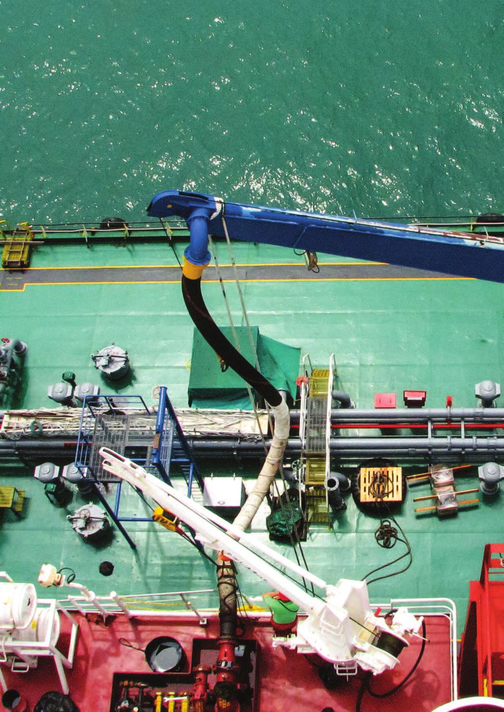
8
9 A responsible engineer should, with the supplier s representative, jointly inspect the supplying barge s gauges and tank measurements and confirm the quantities and grades to be transferred. If in doubt as to the condition of the supplier s connections or hoses, it is reasonable to request review of the supplier s pressure test certificates. The supplier is responsible for his barge or facility and the supply hose to the ship s manifold; the supplier s representative is entitled to also check the manifold connection on the receiving ship before beginning 3. The maximum pumping rate should be agreed, along with the maximum pressure at the receiving manifold, procedures/rates for commencing of transfer and for topping off and also, if required, the maximum air pressure for the final blow-through. Communications systems between the vessel s crew and with the supplier should be agreed and tested. This should include signals for stopping the transfer in an emergency, and transfer should not start until communications are checked and verified. 3. During bunkering On commencement, the manifold pressure should be kept to a minimum until it is clear that the intended tanks are filling, and there is no delivery to unintended tanks, overflow or leakage. When satisfied, the pumping rate should be increased until the agreed pressure/flow rate is reached; this may not necessarily be the maximum. Close monitoring of tank filling rates is required but readings of any remote level gauges should be periodically verified during the bunkering operation by manual ullages or soundings. Regular communication checks with the supplier should be maintained, along with a continual manifold watch throughout the bunkering operation. During rainfall, excess water should be manually drained from the deck and from save-alls as necessary, in order to maintain maximum containment capacity. When topping-off tank levels or reducing capacity by closing full tanks off, the supplier should be warned, and an appropriate reduction in flow rate considered. On completion, and assuming delivery quantities are not in dispute, the supplier may blow through the connection to the vessel with compressed air. It is important that a maximum air pressure is agreed, and that the system is suitably aligned for this operation. No valves may be closed and no disconnection is made until completion of the blow-through is confirmed by the supplier. 4. On completion The manifold valve should be closed. Following disconnection, the hose blank and the bunker manifold blank should be securely fitted without delay. The hose should not be lifted away from the manifold save-all until this has been done. The vessel s fuel system valves should be re-aligned for normal operation. Consideration should be made to leave scupper plugs in place until departure from the port, but all SOPEP equipment should otherwise be secured and restowed appropriately. The Master should confirm to the agent that bunkering operations are completed without incident. Case study Human factors A vessel was stemmed to receive 250 MT of IFO 380 from a barge whilst alongside. The bunkers were to be received in a pair of empty top side tanks, each with a full capacity of 200 cubic metres. As per company management procedures, bunker tanks were not to be filled in excess of 85% capacity, which in this case corresponded to a minimum ullage of 55 cm. The Third Engineer (3/E) was placed in sole charge of performing the bunkering operation, which was commenced into the starboard side tank only at 15:20 hours. At 16:30, the 3/E recorded the ullage of the tank as being 51 cm and yet bunkering operations continued. At 16:35, he saw that the ullage had reduced to 35 cm and rushed to the engine room to divert the bunkers into the port side tank. However, by the time he reached the valve station, the starboard side tank was already overflowing on deck, with oil being spilt overboard. This was a very poorly planned bunkering operation from the outset with an almost complete neglect of the company SMS procedures. The bunkering checklist was ticked off but not in fact implemented. The 3/E should have been supported by another member of the engine room staff during the operation and in ready communication with the bunker barge. Consideration should also have been given to filling both port and starboard tanks at the same time. The tank overflowed from both the forward and aft air vents. At the aft vent, the oil was not contained within the save-all as the vent head was located immediately adjacent to the side plate, allowing oil to land directly on deck. At the forward vent, oil was able to escape because the save-all drain plug was not fitted. Although the main deck scuppers were plugged, oil was still able to flow over the deck containment and into the dock. Investigative findings Bunkering operations should be performed in strict compliance with SMS procedures. Bunkering plans are to be carefully considered by the Chief Engineer and checklists diligently completed at the site of the task, not just a tick box exercise. Bunkering is not a one man job. It requires teamwork and communications with ship and barge personnel. The pollution may have been avoided with better design of the tank vent and save-all arrangements. It s not a save-all if the drain plugs are not fitted or missing! 3 Indeed, they should be invited to do so for verification of sampling procedures. Risk Focus: Safe Bunker Operations 9
.")
10 Summary Key points In spite of provision of suitable procedures, bunker spills still occur with worrying frequency. Common causes include setup or monitoring failures, excessive transfer rates or equipment malfunction (valve or hose failure). Human error is also common, caused or exacerbated by complacency, high work load and fatigue, unfamiliarity, or poor communication. Procedures in place should include: Allow adequate safety margins when stemming bunkers stem only to 85% or 90% capacity, as dictated by the vessel s SMS procedures. Appropriate maintenance and testing of systems and pipelines, including calibration of remote tank gauges. Provision of suitable instructions for operation and for emergency response, including bunker check lists and a bunker plan. Regular bunker/oil spill drills to encourage familiarisation with bunker systems and procedures. Pre-arrival preparations should include: Planning for key personnel availability, including suitable rest periods. Plan for tank capacities and filling sequence. Ensure pipelines are in good order, and empty overflow containment (including save-alls). Test high level and overflow alarms. Ensure SOPEP locker contents are readily available. Diligent completion of the bunker check list at appropriate times not in advance. Carry out a final oil spill drill and appraise all crew of the impending operation and of their expected duties. At the bunker port prior to start: Verify correct alignment of the system valves and isolation/blanking of unused components. Check and double-check this point assume nothing. Prominently display the bunker board with fully completed documentation. Deploy SOPEP equipment, including fitting plugs to save-all drains as well as to scuppers and freeing ports. Control drainage in the event of rainfall. Check the supplying facilities tank measurements, confirm quantities and grades to be transferred, and in which order, and check the condition of the supplier s hose and manifold. Establish communication, especially emergency signals, and agree pumping rates for the various stages of the operation. During bunkering: Start slowly, and build up to full flow rates once appropriate distribution of the fuel (checking none is being delivered where it is not wanted) is established. Confirm pumping rates are at or below the maximum specified. Closely monitor tank filling rates and confirm by soundings as appropriate. Do not place over-reliance on remote gauges. Maintain regular communication with the supplier. Avoid distractions. If in doubt, suspend the operation. It s better to have a delay than a spill. Slow down the flow rate for topping off tanks. On completion: Allow the supplier to blow-through the lines with compressed air. Close the manifold valve. Disconnect and install all relevant blank flanges before removing the bunker hose from the vicinity of the manifold. Realign the fuel system for normal operation. Inform the agent that bunkering has been completed, hopefully without incident. 10 Risk Focus: Safe Bunker Operations
11 About us UK P&I Club UK P&I Club is a leading provider of P&I insurance and other services to the international shipping community. Established in 1865, the UK P&I Club insures over 240 million tonnes of owned and chartered shipping through its international offices and claims network. A (Stable) rated by Standard & Poor s with free reserves and hybrid capital of $597m, the UK P&I Club is renowned for its specialist skills and expertise that ensure best in class underwriting, claims handling and loss prevention services. ukpandi.com Brookes Bell Serving the Marine and Energy Industry since 1903, Brookes Bell operate from Liverpool, London, Glasgow, Shanghai, Hong Kong and Singapore. Brookes Bell lead the market in professional expertise and experience across the major maritime and scientific disciplines. All our full-time personnel work exclusively for us and enable us to provide specialist advice on a wide range of inter-disciplinary areas. Brookes Bell are an ISO 9001 quality approved company with solid and time-tested processes ensuring smooth and reliable completion of all work for our clients. brookesbell.com
12 ukpandi.com brookesbell.com
ANNEX AMENDMENTS TO THE INTERNATIONAL CODE FOR FIRE SAFETY SYSTEMS (FSS CODE) CHAPTER 15 INERT GAS SYSTEMS
 CHAPTER 15 INERT GAS SYSTEMS") Annex 3, page 2 ANNEX AMENDMENTS TO THE INTERNATIONAL CODE FOR FIRE SAFETY SYSTEMS (FSS CODE) CHAPTER 15 INERT GAS SYSTEMS The text of existing chapter 15 is replaced by the following: "1 Application This
Annex 3, page 2 ANNEX AMENDMENTS TO THE INTERNATIONAL CODE FOR FIRE SAFETY SYSTEMS (FSS CODE) CHAPTER 15 INERT GAS SYSTEMS The text of existing chapter 15 is replaced by the following: "1 Application This
RESOLUTION A.567(14) adopted on 20 November 1985 REGULATION FOR INERT GAS SYSTEMS ON CHEMICAL TANKERS
 adopted on 20 November 1985 REGULATION FOR INERT GAS SYSTEMS ON CHEMICAL TANKERS") INTERNATIONAL MARITIME ORGANIZATION A 14/Res.567 16 January 1986 Original: ENGLISH ASSEMBLY - 14th session Agenda item lo(b) IMO RESOLUTION A.567(14) adopted on 20 November 1985 THE ASSEMBLY, RECALLING
INTERNATIONAL MARITIME ORGANIZATION A 14/Res.567 16 January 1986 Original: ENGLISH ASSEMBLY - 14th session Agenda item lo(b) IMO RESOLUTION A.567(14) adopted on 20 November 1985 THE ASSEMBLY, RECALLING
OIL IN NAVIGABLE WATERS REGULATIONS [L.N. 101 of 1968.] under sections 5 and 7. [22nd April, 1968] [Comrnencernent.]
![OIL IN NAVIGABLE WATERS REGULATIONS [L.N. 101 of 1968.] under sections 5 and 7. [22nd April, 1968] [Comrnencernent.]](/thumbs/80/81393535.jpg "OIL IN NAVIGABLE WATERS REGULATIONS [L.N. 101 of 1968.] under sections 5 and 7. [22nd April, 1968] [Comrnencernent.]") OIL IN NAVIGABLE WATERS REGULATIONS [L.N. 101 of 1968.] under sections 5 and 7 [Comrnencernent.] [22nd April, 1968] 1. Short title and interpretation (1) These Regulations may be cited as the Oil in Navigable
OIL IN NAVIGABLE WATERS REGULATIONS [L.N. 101 of 1968.] under sections 5 and 7 [Comrnencernent.] [22nd April, 1968] 1. Short title and interpretation (1) These Regulations may be cited as the Oil in Navigable
CARGO OPERATIONS (TANKER) MANUAL CH.05 BALLAST HANDLING. Rev. No: 2. Page: 1 of PURPOSE
 MANUAL CH.05 BALLAST HANDLING. Rev. No: 2. Page: 1 of PURPOSE") Page: 1 of 5 5.1. PURPOSE To ensure that: The vessel, as applicable, meets MARPOL requirements; There is adequate trim and the propeller is immersed; Stress conditions are within allowable limits during
Page: 1 of 5 5.1. PURPOSE To ensure that: The vessel, as applicable, meets MARPOL requirements; There is adequate trim and the propeller is immersed; Stress conditions are within allowable limits during
Cargo pumps shall not be operated in excess of their designed maximum working parameters.
 Page: 1 of 9 4.1. SCOPE This section provides operating instructions and procedures to be complied with in order to ensure that discharging operations are conducted safely and in accordance with the best
[BUNKERING -- BEST MARITIME PRACTICES FOR THE STATE OF CALIFORNIA]
![[BUNKERING -- BEST MARITIME PRACTICES FOR THE STATE OF CALIFORNIA]](/thumbs/88/114750992.jpg "[BUNKERING -- BEST MARITIME PRACTICES FOR THE STATE OF CALIFORNIA]") A. GENERAL INFORMATION 1. The marine waters of California are environmentally sensitive and a precious environmental and economic resource. Bunkering operations, while routine in many parts of the country,
A. GENERAL INFORMATION 1. The marine waters of California are environmentally sensitive and a precious environmental and economic resource. Bunkering operations, while routine in many parts of the country,
API MPMS Chapter 17.6 Guidelines for Determining the Fullness of Pipelines between Vessels and Shore Tanks
 API MPMS Chapter 17.6 Guidelines for Determining the Fullness of Pipelines between Vessels and Shore Tanks 1. Scope This document describes procedures for determining or confirming the fill condition of
Manual Actuated Boiler Blowdown Valves
 Manual Actuated Boiler Blowdown Valves Installation and Maintenance Instructions 1. Safety information 2. General product information 3. Installation 4. Operation 5. Maintenance 6. Spare parts p.1 1. Safety
Rubber Dock Hose care, Use & Maintenance
 Rubber Dock Hose care, Use & Maintenance Prepared by: Thomas J. Wise VP Corporate Development Contents Revised - July. 2014 1. Novaflex Rubber Dock Hose Testing & Inspection Program 1.1 Introduction -
SLOP RECEPTION AND PROCESSING FACILITIES
 RULES FOR CLASSIFICATION OF SHIPS NEWBUILDINGS SPECIAL SERVICE AND TYPE ADDITIONAL CLASS PART 5 CHAPTER 8 SLOP RECEPTION AND PROCESSING FACILITIES JANUARY 2011 CONTENTS PAGE Sec. 1 General Requirements...
Chapter 2 Preparations for Tank Cleaning Work
 Chapter 2 Preparations for Tank Cleaning Work Preparatory Procedures for Tank Cleaning Work Make preparations for tank cleaning work according to the procedures given below. 1. Formulating the tank cleaning
KBV21i and KBV40i Key Operated Boiler Blowdown Valves Installation and Maintenance Instructions
 4059051/3 IM-P405-48 EMM Issue 3 KBV21i and KBV40i Key Operated Boiler Blowdown Valves Installation and Maintenance Instructions 1. Safety information 2. General product information 3. Installation 4.
ANNEX 2 RESOLUTION MEPC.124(53) Adopted on 22 July 2005 GUIDELINES FOR BALLAST WATER EXCHANGE (G6) THE MARINE ENVIRONMENT PROTECTION COMMITTEE,
 Adopted on 22 July 2005 GUIDELINES FOR BALLAST WATER EXCHANGE (G6) THE MARINE ENVIRONMENT PROTECTION COMMITTEE,") Page 1 RESOLUTION MEPC.124(53) Adopted on 22 July 2005 GUIDELINES FOR BALLAST WATER EXCHANGE (G6) THE MARINE ENVIRONMENT PROTECTION COMMITTEE, RECALLING Article 38(a) of the Convention on the International
Page 1 RESOLUTION MEPC.124(53) Adopted on 22 July 2005 GUIDELINES FOR BALLAST WATER EXCHANGE (G6) THE MARINE ENVIRONMENT PROTECTION COMMITTEE, RECALLING Article 38(a) of the Convention on the International
MSC Guidelines for Vents, Fills and Sounds
 S. J. Kelly, CDR, Chief of Engineering Division References: a. 46 CFR 56.50-85 & 56.50-90 (Subchapter F) b. 46 CFR 32.55, 36.20-1 & 38.20 (Subchapter D) c. 46 CFR 119.445 & 119.450 (Subchapter K) d. 46
APPENDIX 4 STANDARD FORMAT FOR THE PROCEDURES AND ARRANGEMENTS MANUAL
 Page 42 APPENDIX 4 STANDARD FORMAT FOR THE PROCEDURES AND ARRANGEMENTS MANUAL Note 1: Note 2: The format consists of a standardized introduction and index of the leading paragraphs to each section. This
NORMAL OPERATING PROCEDURES Operating Parameter Information
 Operating Parameter Information Each operator performing the normal operating procedures (routine checks) of the facility should be familiar with the current normal operating parameters of all systems
Spirax Compact FREME Flash Recovery Energy Management Equipment
 IM-UK-cFREME UK Issue 1 Spirax Compact FREME Flash Recovery Energy Management Equipment Installation and Maintenance Instructions 1. Safety information 2. General product information 3. Installation 4.
References: Manual Chapt. 9 ISO 9001 par.7 ISO par. 4 ISM Code par. 7; 8
 SQEMS OPERATING PROCEDURE OP-SAF-03 1 of 5 References: Manual Chapt. 9 ISO 9001 par.7 ISO 14001 par. 4 ISM Code par. 7; 8 1. SCOPE This Procedure establishes criteria for the control and management of
Work Permit Help Document For changes introduced in ShIPS Revision 7.1 (Released 11/12/2008)
") Introduction Work Permit Help Document For changes introduced in ShIPS Revision 7.1 (Released 11/12/2008) The current ShIPS Revision 7.1 has introduced an automated work permit system which has the benefit
Introduction Work Permit Help Document For changes introduced in ShIPS Revision 7.1 (Released 11/12/2008) The current ShIPS Revision 7.1 has introduced an automated work permit system which has the benefit
FV Flash Vessel Installation and Maintenance Instructions
 4041050/5 IM-P404-10 EMM Issue 5 FV Flash Vessel Installation and Maintenance Instructions 1. Safety information 2. Specific product safety information 3. Product information 4. Installation 5. Commissioning
COSASCO 3600 PSI SINGLE ISOLATION SERVICE VALVE (FR) MAINTENANCE
 MAINTENANCE") COSASCO 3600 PSI SINGLE ISOLATION SERVICE VALVE (FR) MAINTENANCE Rohrback Cosasco Systems, Inc. 11841 E. Smith Avenue Santa Fe Springs, CA 90670 Tel: (562) 949-0123 (800) 635-6898 Fax: (562) 949-3065 www.cosasco.com
COSASCO 3600 PSI SINGLE ISOLATION SERVICE VALVE (FR) MAINTENANCE Rohrback Cosasco Systems, Inc. 11841 E. Smith Avenue Santa Fe Springs, CA 90670 Tel: (562) 949-0123 (800) 635-6898 Fax: (562) 949-3065 www.cosasco.com
Large container ships Builder s and operational risks John Martin, Managing Director, Gard (Singapore) Pte Ltd. 12 January 2016
 Pte Ltd. 12 January 2016") Large container ships Builder s and operational risks John Martin, Managing Director, Gard (Singapore) Pte Ltd 12 January 2016 Builder s risk on container ships the issues Container ships growing in size
Large container ships Builder s and operational risks John Martin, Managing Director, Gard (Singapore) Pte Ltd 12 January 2016 Builder s risk on container ships the issues Container ships growing in size
CARRIAGE OF DIRECT REDUCED IRON (DRI) BY SEA CHANGES TO THE IMO CODE OF SAFE PRACTICE FOR SOLID BULK CARGO
 BY SEA CHANGES TO THE IMO CODE OF SAFE PRACTICE FOR SOLID BULK CARGO") The Shipowners Protection Limited St Clare House, 30-33 Minories London EC3N 1BP TO ALL MEMBERS March 2010 Managers of The Shipowners Protection Mutual Protection Limited and Indemnity St Clare House,
The Shipowners Protection Limited St Clare House, 30-33 Minories London EC3N 1BP TO ALL MEMBERS March 2010 Managers of The Shipowners Protection Mutual Protection Limited and Indemnity St Clare House,
LNG Marine Loading Arms and Manifold Draining, Purging and Disconnection Procedure
 LNG Marine Loading Arms and Manifold Draining, Purging and Disconnection Procedure i The Society of International Gas Tanker and Terminal Operators (SIGTTO) The Society of International Gas Tanker and
In product vessels, LOT is not normally practiced as the recovered oil is usually discharged to shore reception facilities.
 Page: 1 of 7 12.1. COMPLIANCE WITH MARPOL 12.1.1. Retention of Oil on Board Oil tankers are provided with facilities to enable them to control operational pollution by cleaning cargo tanks using re-circulatory
CRANE WITH WINCH USE AND MAINTENANCE MANUAL. Code Rev. Release MD /03
 CRANE WITH WINCH Code Rev. Release MD.0.097 0 06/03 USE AND MAINTENANCE MANUAL CONTENTS 1 FOREWORD page 3 1.1 Description of the crane with winch page 3 2 USE OF THE CRANE WITH WINCH page 3 2.1 General
E2.14 Control of Hazardous Energy. Effective Date: 03/01/2018
 University Policy Volume E2: Environment, Health, Safety and Security E2.14 Control of Hazardous Energy Responsible Office: Facilities Management Responsible Officer: Safety Officer POLICY STATEMENT All
KBV21i and KBV40i Air Actuated Boiler Blowdown Valves
 4059051/1 IM-P405-48 AB Issue 1 KBV21i and KBV40i Air Actuated Boiler Blowdown Valves Installation and Maintenance Instructions 1. Safety information 2. General product information 3. Installation 4. Commissioning
CAST IRON SAFETY VALVE TYPE 6301
 CHARACTERISTICS The 6301 safety valve is dedicated to protect the equipment from potential overpressure. This is an automatic device that closes when the pressure conditions are back to normal. It is a
SOP GEN-007X Crane and Winch Operations
 Page 1 of 7 SOP GEN-007X 1.0 Introduction 2.0 Responsibility 3.0 References 4.0 Training and Qualifications 5.0 Operational Inspections 6.0 Maintenance and Load Tests 7.0 Cranes 8.0 Winches 9.0 Mobile
PASSENGER SHIPS Guidelines for preparation of Hull Structural Surveys
 (Feb 2010) PASSENGER SHIPS Guidelines for preparation of Hull Structural Surveys Contents 1 Introduction 2 Preparations for Survey 2.1 General 2.2 Conditions for survey 2.3 Access to structures 2.4 Survey
Health and Safety Executive. Key aspects of HS(G) 253. Andrew Hall HID CI 1G. HM Specialist Inspector (Mechanical)
 253. Andrew Hall HID CI 1G. HM Specialist Inspector (Mechanical)") Health and Safety Executive Key aspects of HS(G) 253 Andrew Hall HID CI 1G HM Specialist Inspector (Mechanical) Human Factors Human Failures can be grouped into: Errors And Violations Errors are not intended
Health and Safety Executive Key aspects of HS(G) 253 Andrew Hall HID CI 1G HM Specialist Inspector (Mechanical) Human Factors Human Failures can be grouped into: Errors And Violations Errors are not intended
Government of Bermuda Department of Maritime Administration BERMUDA SHIPPING NOTICE
 Government of Bermuda Department of Maritime Administration 2015 027 BERMUDA SHIPPING NOTICE Maintenance and Inspection of Fixed Carbon Dioxide Fire Extinguishing Systems Ref: SOLAS 74/88 as amended, Regulation
Piped Air SCBA Refilling System Standard
 WALT WHITE Fire Chief 5770 Freeport Blvd., Suite 200 Sacramento, CA 95822-3516 Ph: (916) 808-1300 Fax: (916) 808-1629 www.sacfire.org Piped Air SCBA Refilling System Standard SCOPE: This specification
DESIGN DATA A WET PIPE BLADDER TANK FOAM/WATER SYSTEM WITH HYDRAULICALLY ACTUATED DELUGE CONCENTRATE CONTROL VALVE
 February 9, 1998 Foam 101a A BLADDER TANK WITH 1. DESCRIPTION A Wet Pipe Bladder Tank Foam/Water System is a standard wet pipe automatic sprinkler system capable of discharging a foam/water solution automatically
TITAN FLOW CONTROL, INC.
 PREFACE: This manual contains information concerning the installation, operation, and maintenance of Titan Flow Control (Titan FCI) Simplex Basket Strainers. To ensure efficient and safe operation of Titan
Irrigation System Winterization and Pressurization Procedures
 Irrigation System Winterization and Pressurization Procedures Introduction Any time that an irrigation system is filled and pressurized, or when the system is drained and water flushed from the system,
Lockout/Tagout Training Overview. Safety Fest 2013
 Lockout/Tagout Training Overview Safety Fest 2013 Purpose of Lockout/Tagout The standard covers the servicing and maintenance of machine and equipment in which the unexpected energization or start up of
PRESSURE REDUCING STATION INSTALLATION, OPERATIONS & MAINTENANCE MANUAL
 PRESSURE REDUCING STATION INSTALLATION, OPERATIONS & MAINTENANCE MANUAL Company Registered Office: Crown House, Stockport, Cheshire, SK13RB No. 850 0700 67 Registered in England and Wales No. 05058855
COSASCO 6000 PSI SINGLE ISOLATION SERVICE VALVE (FR) MAINTENANCE
 MAINTENANCE") COSASCO 6000 PSI SINGLE ISOLATION SERVICE VALVE (FR) MAINTENANCE 11841 Smith Avenue Santa Fe Springs, CA 90670 Tel: (562) 949-0123 (800) 635-6898 Fax: (562) 949-3065 www.cosasco.com Page: 2 of 26 Revision
COSASCO 6000 PSI SINGLE ISOLATION SERVICE VALVE (FR) MAINTENANCE 11841 Smith Avenue Santa Fe Springs, CA 90670 Tel: (562) 949-0123 (800) 635-6898 Fax: (562) 949-3065 www.cosasco.com Page: 2 of 26 Revision
SAFETY TRAINING LEAFLET 06 CARBON DIOXIDE
 SAFETY TRAINING LEAFLET 06 CARBON DIOXIDE Doc 23.06/18 EUROPEAN INDUSTRIAL GASES ASSOCIATION AISBL AVENUE DES ARTS 3-5 B 1210 BRUSSELS Tel: +32 2 217 70 98 Fax: +32 2 219 85 14 E-mail: info@eiga.eu Internet:
Site of yoke being supported by shore-side crane
 AB Safety Flash IMCA Safety Flash 16/09 November 2009 These flashes summarise key safety matters and incidents, allowing wider dissemination of lessons learnt from them. The information below has been
Method Statement: Testing Dry Riser System
 Method Statement: Testing Dry Riser System Page 1 of 6 Scope of work Test dry riser system in accordance with BS 5306. Definitions For the purposes of this document, the following definitions apply Rising
USING HAZOP TO IDENTIFY AND MINIMISE HUMAN ERRORS IN OPERATING PROCESS PLANT
 USING HAZOP TO IDENTIFY AND MINIMISE HUMAN ERRORS IN OPERATING PROCESS PLANT Chris Lyth, Tracerco, Billingham, Cleveland, UK Ian Bradby, ABB Engineering Services, Billingham Cleveland, UK This joint paper
Moor, Tend Mooring And Unmoor Ship - Supervisor Level -
 Marine Terminal Operations Competency Standard Moor, Tend Mooring And Unmoor Ship - Supervisor Level - Industry : Oil, Chemical and Gas Industry Competency Category : 2.0 Moor, tend mooring and unmoor
SEAFARER TRAINING RECORD BOOK
 SEAFARER TRAINING RECORD BOOK FOR SKIPPER RESTRICTED LIMITS (SRL) Certificate of competency Endorsed to less than 500 gross tonnage Table of contents Personal details... ii Skipper Restricted Limits (SRL)
PRESSURE SYSTEMS POLICY
 PRESSURE SYSTEMS POLICY PRESSURE SYSTEMS POLICY 1. Introduction 2. Policy Statement 3. Scope 4. Background 5. Roles & Responsibilities 6. Training 7. Contractors 8. Policy Review 1. Introduction The Kilmarnock
Scope: This plan applies to all personnel, including contractors, who enter or work in confined spaces, or supervise such activities.
 11/13/1995 4 5/20/2013 1 of 10 Authority and Scope Regulation: 29 CFR 1910.146 Scope: This plan applies to all personnel, including contractors, who enter or work in confined spaces, or supervise such
Blowdown vessels Meeting the requirements of HSE PM60
 Blowdown vessels Meeting the requirements of HSE PM60 BDV60 blowdown vessels A complete range of equipment for the safe disposal of boiler blowdown Boiler blowdown Steam boilers must be blown down to remove
The Discussion of this exercise covers the following points:
 Exercise 5-3 Wet Reference Leg EXERCISE OBJECTIVE Learn to measure the level in a vessel using a wet reference leg. DISCUSSION OUTLINE The Discussion of this exercise covers the following points: Measuring
TEST BENCH SAFETY VALVES ¼ - 5 DN10 DN125
 TEST BENCH SAFETY VALVES ¼ - 5 DN10 DN125 Model: VC-40-VYC Table of contents 1. - Installing the test bench 1.1.1- Connecting the compressed air / nitrogen source 1.1.2- Maximum test pressure according
New AQF Filter Polymer Filtration System
 New AQF Filter Polymer Filtration System Operator Manual Covering Serial Number 20002001 onwards February 2011 Index Disclaimer notice...3 Introduction...4 Important safety notices...5 Getting started...6
COSASCO 6000 PSI DOUBLE ISOLATION SERVICE VALVE MAINTENANCE
 COSASCO 6000 PSI DOUBLE ISOLATION SERVICE VALVE MAINTENANCE 11841 Smith Avenue Santa Fe Springs, CA 90670 Tel: (562) 949-0123 (800) 635-6898 Fax: (562) 949-3065 www.cosasco.com Page: 2 of 28 Revision History
Every things under control High-Integrity Pressure Protection System (HIPPS)
") Every things under control www.adico.co info@adico.co Table Of Contents 1. Introduction... 2 2. Standards... 3 3. HIPPS vs Emergency Shut Down... 4 4. Safety Requirement Specification... 4 5. Device Integrity
Every things under control www.adico.co info@adico.co Table Of Contents 1. Introduction... 2 2. Standards... 3 3. HIPPS vs Emergency Shut Down... 4 4. Safety Requirement Specification... 4 5. Device Integrity
Pressure Systems Safety Regulation
 Pressure Systems Safety Regulation Introduction This document informs Faculty of the key requirements of the UK and Chinese Pressure Systems Safety regulations. The aim of these regulations is to prevent
SUP 15 Health & Safety Management Pressure Systems. Unified procedures for use within NHS Scotland
 SUP 15 Health & Safety Management Pressure Systems Unified procedures for use within NHS Scotland September 2015 Contents Page Acknowledgements... 3 1. Introduction... 4 2. Purpose of this Procedure...
Tanker Officer Training Standards (TOTS) 4C Product Tanker Simulator Training Course
 4C Product Tanker Simulator Training Course") Tanker Officer Training Standards (TOTS) 4C Product Tanker Simulator Training Course Tanker Officer Training Standards (TOTS) 4C Product Tanker Simulator Training Course CONTENTS Prerequisites...1 TOTS
Tanker Officer Training Standards (TOTS) 4C Product Tanker Simulator Training Course Tanker Officer Training Standards (TOTS) 4C Product Tanker Simulator Training Course CONTENTS Prerequisites...1 TOTS
Working Environment Safety Assessment
 For your own safety and/or safety of your workforce, and to improve the efficiency of your business practices, you should be aware of, and be up to date with, the key safety issues and good practices relevant
Compiled by: B Beard. Approved by: SH Carstens. Description of requirements and procedures for compact provers to be used as verification standards.
 1. Scope Description of requirements and procedures for compact provers to be used as verification standards. 2. Reference documents Trade Metrology Act SANS1698 3. Policy A. BASIC REQUIREMENTS Compact
INSTALLATION, OPERATION AND SERVICE MANUAL ABS AIR BAG LIFT
 INSTALLATION, OPERATION AND SERVICE MANUAL ABS AIR BAG LIFT P.O. Box 1058 1058 West Industrial Avenue Guthrie, OK 73044-1058 405-282-5200 FAX: 405-282-8105 www.autoquip.com Item # 830ABS Version 1.0 07/2001
HUMAN FACTORS CHECKLIST
 HUMAN FACTORS CHECKLIST Item I. Housekeeping and General Work Environment 1 Are adequate signs posted near maintenance, cleanup, or staging areas to warn workers of special or unique hazards associated
We re Going Global. Vessel Loss Control. Technical Notes #36
 Technical Notes #36 We re Going Global Vessel Loss Control When the vessel loaded, the gauging reports showed x amount but when it arrived at its discharge port, why was the amount vastly different? In
Types 749B and R130 Changeover Manifolds
 Instruction Manual MCK-1179 Types 749B and R130 June 2012 Types 749B and R130 Changeover Manifolds TYPE HSRL-749B TYPE 64SR/122 TYPE R130/21 TYPE 749B/21 Figure 1. Changeover Manifolds and Regulator Assemblies
Circular No. 3/ March To the members. Dear Sirs,
 GARD AS Circular No. 3/2010 16 March 2010 To the members Postbox 789 Stoa NO-4809 ARENDAL NORWAY Tel +47 37 01 91 00 Fax +47 37 02 48 10 companymail@gard.no www.gard.no Dear Sirs, Carriage of Direct Reduced
CPX EMERGENCY STANDBY MANIFOLD INSTALLATION, OPERATIONS & MAINTENANCE MANUAL
 CPX EMERGENCY STANDBY MANIFOLD INSTALLATION, OPERATIONS & MAINTENANCE MANUAL Company Registered Office: Crown House, Stockport, Cheshire, SK13RB No. 850 0700 67 Registered in England and Wales No. 05058855
THE BAKER REPORT HOW FINDINGS HAVE BEEN USED BY JOHNSON MATTHEY TO REVIEW THEIR MANUFACTURING OPERATIONS
 THE BAKER REPORT HOW FINDINGS HAVE BEEN USED BY JOHNSON MATTHEY TO REVIEW THEIR MANUFACTURING OPERATIONS Colin P. Lynas, Elizabeth Campbell and Hendrik J. Koornhof Johnson Matthey Catalysts This paper
INSTRUCTOR GUIDE REFERENCES: PUMPING APPARATUS DRIVER/OPERATOR HANDBOOK, FIRST EDITION, IFSTA
 TOPIC: RELAY PUMPING OPERATIONS LEVEL OF INSTRUCTION: TIME REQUIRED: ONE HOUR INSTRUCTOR GUIDE MATERIALS: APPROPRIATE AUDIO VISUAL SUPPORT REFERENCES: PUMPING APPARATUS DRIVER/OPERATOR HANDBOOK, FIRST
Instrument Operating Manual
 Instrument Operating Manual INDEX NO. SUBJECT PAGE 1 INFORMATION 3 2 SAFETY 4 3 INTENDED USE 4 4 COMMISSIONING & OPERATION 5 5 MAINTENANCE 6 2 INFORMATION The pressure gauges described in the operating
Good Morning everyone, I will be talking this morning about the review and restructure of Cruise Whitsundays Safety Management Systems.
 Good Morning everyone, I will be talking this morning about the review and restructure of Cruise Whitsundays Safety Management Systems. 1 This presentation is about the restructure of Cruise Whitsundays
MANUAL GAS MANIFOLDS
 MANUAL GAS MANIFOLDS Phoenix Pipeline Products Limited. Unit 8, McKenzie Industrial Park, Tel No.: 44 (0) 161 428 7200 Bird Hall Lane, Fax No.: 44 (0) 161 428 7010 Stockport, Email: info@p3-phoenix.com
Scald Protection Three-Way Thermostatic Mixing Valve
 CALEFFI www.caleffi.com 383.04 Scald Protection Three-Way Thermostatic Mixing Valve Copyright 00 Caleffi 3 Series Installation, commissioning and servicing instructions Function Scald Protection Three-Way
BUTTERFLY VALVES Series 800
 BUTTERFLY VALVES Series 800 WARNING Before proceeding read ALL instructions and become familiar with the equipment and associated drawings. Follow ALL applicable safety regulations and codes for pressurized
Pressure Relief Valve Instruction Manual
 CVR3-M0_062017 Pressure Relief Valve Instruction Manual MODEL: CVR3 SFA Companies 10939 N. Pomona Ave. Kansas City, MO 64153 Tel: 888-332-6419 * Fax: 816-448-2142 E-mail: sales@bvahydraulics.com Website:
AcornVac Vacuum Plumbing Systems - Trouble Shooting Guide
 AcornVac Vacuum Plumbing Systems - Trouble Shooting Guide 1. Accumulators Problem Accumulator is overflowing If Accumulator continues to overflow Correction 1. Push and hold the manual activation button
IMPORTANT INFORMATION
 IMPORTANT INFORMATION READ THE COMPLETE DOCUMENTATION BEFORE USE EC DECLARATION OF CONFORMITY In accordance with the Directive Explosive Atmosphere 94/9/EC (ATEX) and Pressure Equipment Directive 2014/68/EU
RESOLUTION MEPC.86(44) adopted on 13 March 2000 AMENDMENTS TO THE GUIDELINES FOR THE DEVELOPMENT OF SHIPBOARD OIL POLLUTION EMERGENCY PLANS
 adopted on 13 March 2000 AMENDMENTS TO THE GUIDELINES FOR THE DEVELOPMENT OF SHIPBOARD OIL POLLUTION EMERGENCY PLANS") MEPC 44/20 RESOLUTION MEPC.86(44) THE MARINE ENVIRONMENT PROTECTION COMMITTEE, RECALLING Article 38(a) of the Convention on the International Maritime Organization concerning the function of the Committee,
MEPC 44/20 RESOLUTION MEPC.86(44) THE MARINE ENVIRONMENT PROTECTION COMMITTEE, RECALLING Article 38(a) of the Convention on the International Maritime Organization concerning the function of the Committee,
FM Approved - Automatic Water Control Valve as standard deluge valve. No formal approval available for coating. Foam Concentrate
 December 6, 2010 Foam 31a 1. Description With Multiple Pilot Pressure Regulating Foam/Water Deluge Systems Supplied by a Bladder Tank, multiple pilot pressure regulating foam risers can be supplied from
PV4 and PV6 Piston Valves
 1181250/1 IM-P118-05 ST Issue 1 PV4 and PV6 Piston Valves Installation and Maintenance Instructions 1. Safety information 2. General product information 3. Installation 4. Commissioning 5. Operation 6.
Energy Control. Suite 2A, 55 Frid Street Hamilton, ON L8P 4M3 office: cell:
 Energy Control Suite 2A, 55 Frid Street Hamilton, ON L8P 4M3 office: 905.577.0303 cell: 905.977.0210 consultant@staffaid.ca www.staffaid.com Safety, Energy Control, Power Lockout & Function Test Procedures
RLPG Terminals, Ras Tanura, Ju aymah, Yanbu
 RLPG Terminals, Ras Tanura, Ju aymah, Yanbu 1 Table of Contents 1 General... 1 1.1 Application... 1 1.2 Jurisdiction... 1 1.3 Unsafe Conditions... 1 1.4 Berth Assignment... 1 1.5 Acceptability... 1 1.6
Airfix D-E-B Installation and operating instructions
 www.flamco.nt-rt.ru Airfix D-E-B Installation and operating instructions Dear Customer, With the Airfix D-E-B membrane expansion vessel you have acquired a Flamco quality product. This expansion vessel
RESOLUTION MEPC.288(71) (adopted on 7 July 2017) 2017 GUIDELINES FOR BALLAST WATER EXCHANGE (G6)
 (adopted on 7 July 2017) 2017 GUIDELINES FOR BALLAST WATER EXCHANGE (G6)") Annex 9, page 1 ANNEX 9 RESOLUTION MEPC.288(71) (adopted on 7 July 2017) THE MARINE ENVIRONMENT PROTECTION COMMITTEE, RECALLING Article 38(a) of the Convention on the International Maritime Organization
Annex 9, page 1 ANNEX 9 RESOLUTION MEPC.288(71) (adopted on 7 July 2017) THE MARINE ENVIRONMENT PROTECTION COMMITTEE, RECALLING Article 38(a) of the Convention on the International Maritime Organization
Installation Operation Maintenance. Bermad Level Control Valve with Modulating Horizontal Float Pilot valve One Way Flow IOM.
 Bermad Level Control Valve with Modulating Horizontal Float Pilot valve One Way Flow Model: FP 450-80 Installation Operation Maintenance PAGE 1 OF 5 1. Safety First BERMAD believes that the safety of personnel
GUIDELINES FOR SURVEY OF OIL FLOATING STORAGE VESSELS FIXED AT ANCHORAGE
 GUIDANCE NOTES GD03-2017 CHINA CLASSIFICATION SOCIETY GUIDELINES FOR SURVEY OF OIL FLOATING STORAGE VESSELS FIXED AT ANCHORAGE 2017 Effective from 1 March 2017 BEIJING Chapter 1 GENERAL 1.1 Application
Lockout / Tag out Program
 Lockout / Tag out Program Presented by DOSHTI www.doshti.com You will learn Purpose of Lockout- Tag out Requirements for LOTO Types of Hazardous Energy Procedures for LOTO The OSHA Standard for the Control
An airbag was attached to the WCR tool and inflated to allow the WCR tool to rotate on the pipeline and free the diver.
 AB Safety Flash IMCA Safety Flash 03/09 March 2009 These flashes summarise key safety matters and incidents, allowing wider dissemination of lessons learnt from them. The information below has been provided
MSC-P and MSC-N Manifolds for Steam Distribution and Condensate Collection
 1170850/1 IM-P117-36 ST Issue 1 MSC-P and MSC-N Manifolds for Steam Distribution and Condensate Collection Installation and Maintenance Instructions 1. Safety information 2. General product information
Health and Safety at Work (Hazardous Substances Reduced Secondary Containment for Certain Above Ground Stationary Tanks) Safe Work Instrument 2017
 Safe Work Instrument 2017") Health and Safety at Work (Hazardous Substances Reduced Secondary Containment for Certain Above Ground Stationary Tanks) Safe Work Instrument 2017 This safe work instrument is approved under section 227
Health and Safety at Work (Hazardous Substances Reduced Secondary Containment for Certain Above Ground Stationary Tanks) Safe Work Instrument 2017 This safe work instrument is approved under section 227
Tentec. Instruction Document. Mini Air Driven Pump Unit Model: HTT.627X Series. Part Identifier
 Tentec Page 1 w w w. t e n t e c. n e t Instruction Document Mini Air Driven Pump Unit Model: HTT.627X Series HTT.6271 Maximum Working Pressure = 1500bar (21750 psi) HTT.6272 Maximum Working Pressure =
INTERNATIONAL MARITIME ORGANIZATION
 Page 1 of 16 INTERNATIONAL MARITIME ORGANIZATION IMO Resolution A.586(14) REVISED GUIDELINES AND SPECIFICATIONS FOR OIL DISCHARGE MONITORING AND CONTROL SYSTEMS FOR OIL TANKERS. ANNEX This document quote
OCTOBER 2017 ISSUE Page 1 of 7
 Field testing is performed on fully assembled pipelines for the purpose of determining pipeline acceptability. Following visual acceptance of joints and pipeline components, pressure pipelines in their
BCGA GUIDANCE NOTE 17
 BCGA GUIDANCE NOTE 17 BCGA POLICY AND GUIDANCE FOR THE SAFE FILLING OF THIRD-PARTY OWNED AND / OR MAINTAINED TANKS Revision 2: 2013 BCGA GUIDANCE NOTE 17 BCGA POLICY AND GUIDANCE FOR THE SAFE FILLING OF
POTENTIAL HEALTH & SAFETY HAZARDS
 Number: OH&S 18.09.1 Revision Date: 2011.06 Confined Space 1. PURPOSE 2. SCOPE 1.1. To properly designate Confined Spaces (CS) at Thompson Rivers University (TRU), to provide guidance to ensure the safety
Periodic Survey of Fuel Installations on Ships other than Liquefied Gas Carriers utilizing gas or other low flash point fuels
 (Jan 2017) Periodic Survey of Fuel Installations on Ships other than Liquefied Gas Carriers utilizing gas or other low flash point fuels CONTENTS 1. Application 2. Special Survey 2.1 Schedule 2.2 Scope
Discharge Relief Valve Operation & Maint.
 Relief Valve Operation & Maint. CZ Series Centrifugal Fire Relief svalve Operation and Maintenance Instructions 1410 Operation and Maintenance Form No. F-1031 Section 2302.6 2111 Issue Date 04/90 11/95
This written Compressed Gas Plan is kept at the corporate office and in the written Safety & Health Program.
 Safety & Health Program 10627 Midwest Industrial Boulevard, St. Louis, MO Phone: 314-785-6425 Fax: 314-785-6426 Compressed Gas Plan Purpose It is the policy of EMA to permit only trained and authorized
Subject Maintenance, inspection and test of Fire-Protection Systems and Appliances on board the Panama-registered ships To whom it may concern Technic
 Subject Maintenance, inspection and test of Fire-Protection Systems and Appliances on board the Panama-registered ships To whom it may concern Technical Information No. TEC-0869 Date 14 October 2011 The
National Maritime Center
 National Maritime Center Providing Credentials to Mariners (Sample Examination) Page 1 of 11 Chose the best answer to the following Multiple Choice Questions. 1. In reference to accidental oil pollution,
AWG Fittings LLC. Pressure Relief Valve Up to 250 PSI. Product Number Read this instruction manual before use.
 AWG Fittings LLC Pressure Relief Valve Up to 250 PSI Product Number 30004033 Read this instruction manual before use. Using this device without t understanding di this products operation and care may lead