MODEL TURBO 2 TURBO 2 P PORTABLE TRACE OXYGEN ANALYZER INSTRUCTION MANUAL
|
|
|
- Noel Hancock
- 5 years ago
- Views:
Transcription
1 MODEL TURBO 2 TURBO 2 P PORTABLE TRACE OXYGEN ANALYZER INSTRUCTION MANUAL Sales Order Number: Instrument Serial Number: DANGER HIGHLY TOXIC AND OR FLAMMABLE LIQUIDS OR GASES MAY BE PRESENT IN THIS MONITORING SYSTEM. PERSONAL PROTECTIVE EQUIPMENT MAY BE REQUIRED WHEN SERVICING THIS SYSTEM. HAZARDOUS VOLTAGES EXIST ON CERTAIN COMPONENTS INTERNALLY WHICH MAY PERSIST FOR A TIME EVEN AFTER THE POWER IS TURNED OFF AND DISCONNECTED. ONLY AUTHORIZED PERSONNEL SHOULD CONDUCT MAINTENANCE AND/OR SERVICING. BEFORE CONDUCTING ANY MAINTENANCE OR SERVICING CONSULT WITH AUTHORIZED SUPERVISOR/MANAGER. P/N M /11/2012
2 Copyright 2000 All Rights Reserved. No part of this manual may be reproduced, transmitted, transcribed, stored in a retrieval system, or translated into any other language or computer language in whole or in part, in any form or by any means, whether it be electronic, mechanical, magnetic, optical, manual, or otherwise, without the prior written consent of, Chestnut Street, City of Industry, CA Warranty This equipment is sold subject to the mutual agreement that it is warranted by us free from defects of material and of construction, and that our liability shall be limited to replacing or repairing at our factory (without charge, except for transportation), or at customer plant at our option, any material or construction in which defects become apparent within one year from the date of shipment, except in cases where quotations or acknowledgements provide for a shorter period. The Class S-2 Micro-Fuel Cell is warranted for 6 months from the date of shipment from Teledyne. Components manufactured by others bear the warranty of their manufacturer. This warranty does not cover defects caused by wear, accident, misuse, neglect or repairs other than those performed by Teledyne or an authorized service center. We assume no liability for direct or indirect damages of any kind and the purchaser by the acceptance of the equipment will assume all liability for any damage which may result from its use or misuse. We reserve the right to employ any suitable material in the manufacture of our apparatus, and to make any alterations in the dimensions, shape or weight of any parts, in so far as such alterations do not adversely affect our warranty. Important Notice This instrument is intended to be used as a tool to gather valuable data. The information provided by the instrument may assist the user in eliminating potential hazards caused by the process that the instrument is intended to monitor; however, it is essential that all personnel involved in the use of the instrument or its interface with the process being measured be properly trained in the process itself, as well as all instrumentation related to it. The safety of personnel is ultimately the responsibility of those who control process conditions. While this instrument may be able to provide early warning of imminent danger, it has no control over process conditions, and can be misused. In particular, any alarm or control system installed must be tested and understood, both as to how they operate and as to how they can be defeated. Any safeguards required such as locks, labels, or redundancy must be provided by the user or specifically requested of Teledyne when the order is placed. The purchaser must be aware of the hazardous conditions inherent in the process(es) he uses. He is responsible for training his personnel, for providing hazard warning methods and instrumentation per the appropriate standards, and for ensuring that hazard warning devices and instrumentation are maintained and operated properly. (TAI), the manufacturer of this instrument, cannot accept responsibility for conditions beyond its knowledge and control. No statement expressed or implied by this document or any information disseminated by the manufacturer or his agents is to be construed as a warranty of adequate safety control under the user s process conditions.
3 Table of Contents Introduction... 1 Method of Analysis... 1 Features... 2 Supporting Equipment and Services... 5 Sampling Equipment... 5 Power Service... 6 Operation... 7 Calibration... 8 Positive Pressure Sampling... 9 Atmospheric Pressure Sampling Maintenance Recharging the Battery Routine Maintenance Cell Replacement Cell Warranty Transduction and Temperature Compensation Pump Removal/Installation Appendix Specifications Spare Parts List Drawing List Material Safety Data Sheet... 17
4
5 Portable Trace Oxygen Analyzer TURBO 2 Introduction The Model TURBO 2 is a portable trace oxygen analyzer which does not need an external power source to operate, and can be reliably calibrated without the use of additional calibration gases. The instrument provides for trace oxygen analysis in measuring ranges of 0-100, 0-1,000 and 0-10,000 PPM (full scale), plus a special calibration range that encompasses the known oxygen concentration of atmospheric air (209,000 PPM). Sample oxygen is read from an extremely accurate integral meter (0.5% linearity) whose range of measurement is determined by the position of the range selector switch. The 100-division meter scale and the multiplying factor indicated by the position of the range switch determine the full scale oxygen sensitivity of the instrument. Sample gas is introduced and vented via a pair of quick disconnect fittings that feature integral shutoff valves which automatically close when the mating male fitting is withdrawn. The fittings are an integral part of the measuring cell manifold so that internal sample passage volume is at an absolute minimum. Sample flow control, although not critical (0.1 to 10 liters/min.), is either accomplished with accessory equipment or by the addition of a pump and flowmeter (TURBO 2 P). Method of Analysis The sample oxygen is measured by a unique electrochemical transducer which functions as a fuel cell; in this instance, the fuel is oxygen. Oxygen diffusing into the cell reacts chemically to produce an electrical current that is proportional to the oxygen concentration in the gas phase immediately adjacent to the transducer s sensing surface. The Micro-fuel Cell is a Class S-2, designed for a quick recovery time from air to low PPM levels of oxygen. 1
6 TURBO 2 Portable Trace Oxygen Analyzer The linear, but minute, signal produced by the transducer from trace oxygen is amplified by a two stage amplifier. The dual stages of amplification provide enough gain to drive the microampere meter and thermistor controlled network utilized to compensate for the positive temperature coefficient of the transducer. Features Micro-Fuel Cell:The Micro-fuel Cell (U.S. Pat. #s 3,767,552 and 3,668,101) is a sealed electrochemical transducer with no electrolyte to change or electrodes to clean. When the cell reaches the end of its useful life, it is merely thrown away and replaced, as one would replace a worn-out flashlight battery. The life of the cell is warranted by TAI (see Cell Warranty, page 11). Reliable Calibration: The unique qualities of the Micro-fuel Cell allows the user to calibrate the instrument with the most economical, reliable, abundant, standardization gas there is atmospheric air. The special CAL range of the instrument features a mark that coincides with the 209,000 PPM oxygen concentration of air. By drawing air through the instrument (see Calibration, page 6) reliable calibration can be achieved. After the electronics have been properly zeroed (a one-time factory operation), the instrument cannot produce an output indication in the absence of oxygen; therefore, there is no need for a zero standardization gas. Integral Power Supply: For pump option 4, the differential power requirement (+ and 3.6 VDC) of the instrument amplifier is furnished by two internally mounted 750 milliampere hour NiCad batteries. Fully charged, these batteries will provide enough power to operate the instrument continuously for a period of about 45 days with the pump option OFF. With the pump option ON, the batteries will provide continuous operation for about 8 hours. With the pump option OFF, an overnight charge of hours on a one-month duty cycle should keep the original batteries supplied usable for many years. With the pump option ON, charge hours on an 8-hour duty cycle. An integral charging circuit and a detachable power cord are provided so that the batteries may be recharged from any 50 or 60 cycle, 105 to 125 volt (90 to 110 volt optional), outlet. 2
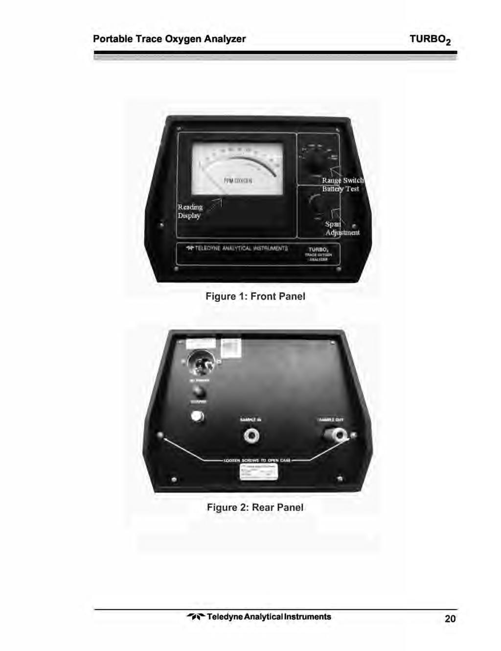
7 Portable Trace Oxygen Analyzer TURBO 2 The instrument is designed to either sample or have its batteries recharged. Both operations cannot be carried out simultaneously. TAI has deliberately interlocked the circuitry so that both operations cannot be carried out at the same time. Only when the selector switch is placed in the OFF position will the neon lamp on the back plate of the Model TURBO 2 light up to indicate power to the battery charging circuit. To determine the state of the rechargeable batteries, turn the Range Selector Switch counterclockwise to the battery test position and hold there (the switch is spring loaded). Watch the meter indicator: if it does not stay within the battery limits, the batteries need to be recharged. Release the Range Selector Switch and it will automatically return to the OFF position. Accuracy and Response: The Model TURBO 2 provides monitoring accuracies of ±2% of full scale or ±5 PPM, whichever is greater, at constant temperature. A ±5% of reading accuracy is achievable throughout the operating temperature range of 30 to 125 F. With a sample flowrate of 150 cc/min., 90% response is achieved in 5 10 seconds in the 0 10, 0 100, , and CAL range switch positions. Compact Packaging: The instrument is housed in 10¹/16 " W 7½ " H 6¾ " D aluminum case that is equipped with a carrying handle and foot pads. When in use, the analyzer should be placed in an upright position on a level surface (off-level positioning will detract from meter accuracy). See Fig.1. The cell block and amplifier PC board are housed inside the analyzer. The back panel of the analyzer contains the AC power receptacle, the amber charge light, fuse (½A: 110V; ¼A: 220V), and quick-connect fittings for bringing the sample into and out of the sensor assembly. See Figs. 2 and 3. Pump: The TURBO 2 P has an integral pump used to help draw sample through the analyzer. 3
8 TURBO 2 Portable Trace Oxygen Analyzer 4
9 Portable Trace Oxygen Analyzer TURBO 2 Supporting Equipment and Services Sampling Equipment The customer must provide a means of controlling the pressure and flowrate of the sample gas. For positive pressure applications, TAI suggests a simple throttle valve installed in the sample line between the sample point and the analyzer. The flowrate should be limited to between 0.1 and 10 liters/min. IMPORTANT: Use pressure regulators with a metallic diaphragm ONLY. Regulators with organic or plastic diaphragms are permeable to oxygen and, if used in the sampling system, will lead to high oxygen readings. For atmospheric pressure sampling, the TURBO 2 P has a pump and flow control valve downstream of the analyzer to draw (rather than push) the sample through the instrument. TAI supplies three (3) male disconnect fittings with the instrument: one for installation of the customer s sample line, one to be used to open the vent fitting of the instrument, and one (equipped with a plastic tube) for drawing air through the unit for calibration purposes. Do not place any restriction on the line between the sample point and the analyzer as a partial vacuum would then be drawn on the cell. Since the cell is a partial pressure sensitive device, any oxygen readings taken under these conditions would be erroneous. In addition, vacuums in excess of one-third of an atmosphere may damage the cell. 5
10 TURBO 2 Portable Trace Oxygen Analyzer Power Service A source of single phase, 105 to 125 VAC (90 to 110 VAC optional), 50 or 60 Hz power, capable of delivering a maximum of ¼ A of current will be periodically required to recharge the instrument s battery power supply. An 8-foot, UL approved, 3-wire detachable power cord is provided with the instrument and should be stored in a safe place when not in use. The TURBO 2 can be optionally furnished with 220 VAC, 50 or 60 Hz charging power or 100 VAC, 50 or 60 Hz charging power. 6
11 Portable Trace Oxygen Analyzer TURBO 2 Operation WARNING: The TURBO 2 is NOT intrinsically safe and must not be used in or brought into hazardous areas. The TURBO 2 is supplied completely assembled and ready for instant use. The Micro-fuel Cell is in place within the manifold, and prior to shipment the manifold was purged with an inert gas to eliminate all but traces of oxygen from the internal sampling system. The integral shut-off valves in the quick disconnect sample fittings, if not disturbed, will maintain this inert atmosphere within the manifold indefinitely. This can be demonstrated by placing the Range Selector Switch in the PPM position. When the range selector is moved from the OFF position, power to the instrument circuitry is established. The meter will instantly respond to the residual oxygen within the integral sample passages. It is impossible to achieve a perfect seal of the internal sample system, and what the meter is indicating is the diffusion/consumption balance point of the internal sample system and the Micro-fuel cell. This balance point, with a properly calibrated instrument, is always within the limits of the range. If the reading climbs off the limits of this scale, a leak in the manifold assembly is indicated. To extend cell life and minimize the time required to make the next analysis, the instrument should always be purged with sample or an inert gas prior to being taken out of service for standby or storage. 7
12 TURBO 2 Portable Trace Oxygen Analyzer Calibration The inherently constant output of the cell during its useful life precludes a definitive calibration cycle. TAI feels that the interval between calibrations should be dictated by your application. If the instrument is being used to certify the oxygen content of a product for delivery, then, a calibration prior to certification would be in order. If not, a biweekly or monthly calibration is adequate. However, the rapid response of the S-2 cell allows more frequent air calibrations than possible with earlier type instruments. NOTE: Do not calibrate the instrument unless there is a trace oxygen gas readily available for purging immediately following calibration. To calibrate the instrument: 1) Stand the instrument upright on a level surface, and with the Range Selector Switch in the OFF position, check the alignment of the meter pointer with the zero mark on the scale. Use the mirror to eliminate parallax, and adjust the screw on the face of the meter, if necessary, until the pointer and zero mark are in precise coincidence. 2) Move the Range Selector Switch to the CAL position. 3) Install the plastic tube equipped male disconnect fitting in either of the analyzer s sample ports, and a blank disconnect fitting in the other port (direction of sample flow is of no importance). A pump is recommended on the plastic tube. Pump the tube until the meter reading is stable. WARNING: DO NOT ATTEMPT TO DRAW SAMPLE THROUGH THE ANALYZER ORALLY. The sensor electrolyte is caustic. Do not let it come in contact with skin. If it does, immediately flush affected area with water. Consult the Emergency First Aid procedures in the Material Safety Data Sheet at the end of the manual. Do not attempt to open or repair the sensor. Leaking or exhausted sensors should be disposed of in accordance with local regulations. Consult the Material Safety Data Sheet at the end of the manual. 4) Unlock and adjust the SPAN potentiometer until the meter pointer is in coincidence with the CAL mark on the meter scale. Be sure to relock the control after the adjustment is made. 5) Immediately after step 4, disconnect the tubing-equipped calibration fitting, and plug in either the sample or a source of inert gas. 8
13 Portable Trace Oxygen Analyzer TURBO 2 If the instrument is to be used for sampling after the calibration procedure has been completed, follow the decreasing oxygen reading by positioning the Range Selector Switch so that the meter gives the best possible resolution of the oxygen. Do not attempt to actually take a reading until the meter indication stabilizes. If, on the other hand, the instrument is not to be used immediately after calibration, and a low PPM oxygen gas is being employed as a purge, allow the manifold to be purged overnight, and then disconnect both male fittings. Always disconnect the source fitting first and then the vent fitting immediately after. Positive Pressure Sampling When connecting the instrument to a positive pressure sample source, always proceed as follows: 1) Before making any connections to the instrument, establish a flowrate in the sample line of from 0.1 to 10 liters/min. Allow the sample to vent to atmosphere long enough to purge the line free of air. 2) Install the vent fitting first, and then the sample source fitting. Be prepared to make the connections in rapid order, so that atmospheric diffusion time through the vent fitting is held to a minimum. When disconnecting the instrument, reverse the procedure: source fitting first, and then vent fitting. The objective of the connection disconnection procedure is to obviate the possibility of pressurizing the manifold. If a flowing sample is connected to the manifold without the vent fitting in place, the pressure in the manifold will rise and equal the sample pressure immediately, possibly causing a manifold leak. 9
14 TURBO 2 Portable Trace Oxygen Analyzer Atmospheric Pressure Sampling The TURBO 2 P is equipped with a sample pump and flowmeter to draw sample through the analyzer in the case of sample at atmospheric or slightly less than atmospheric pressure. The pump power switch is located on the back panel of the analyzer. During calibration and normal operation, set the flowmeter to midrange, and turn the pump on during step 3 of the calibration procedure. 10
15 Portable Trace Oxygen Analyzer TURBO 2 Maintenance Recharging the Battery TAI suggests that an overnight recharge be performed every 4 weeks of continuous use. To recharge the batteries: CAUTION: 1. Move the Range Selector Switch to OFF and connect the power cord to a convenience outlet. The amber charge lamp (back of case) will light during charging. The integral charging circuit will automatically energize and regulate the battery charging current when the Range Selector Switch is in the OFF position and the AC cord is plugged into the power line. Do not turn the Range Selector Switch to either BATT TEST or any of the operating range positions while the unit is connected to AC power. Doing so may cause failure of the integrated circuit. 2. When recharging is completed, unplug the unit from the AC outlet. Turn the Range Selector Switch to the operating position and then to the BATT TEST position. Meter reads 60%-80% fs. NOTE: The BATT TEST position will not give a reliable indication of the battery charge immediately after a charge cycle. Allow the unit to run for a while before testing the batteries. If the instrument is stored with the Range Selector Switch in the OFF position (charge cord disconnected), the period of time between charge periods is extended from one month to four months. However, do not leave it longer than this time period. 11
16 TURBO 2 Portable Trace Oxygen Analyzer Routine Maintenance Beyond adhering to a battery recharge schedule, no routine maintenance is required, as there are no moving parts in the instrument other than the meter movement. The Micro-fuel Cell is a sealed, modular component that should be replaced only when expired or faulty. Cell Replacement The characteristics of the Micro-fuel Cell are similar to those of a mercury battery in that both provide an almost constant output through their useful life, and then fall off sharply towards zero at the end. If the sample being analyzed has a low oxygen concentration, cell failure will probably be indicated by the inability to properly calibrate the analyzer. You will find that very little adjustment of the SPAN potentiometer will be required to keep the analyzer calibrated properly during the duration of a given cell s useful life. If many turn adjustments clockwise are required to calibrate the instrument, or calibration cannot be achieved within the range of the control, the cell should be replaced. To offset the possibility of not having a replacement cell available when it is needed, TAI recommends that a spare cell be purchased shortly after the instrument is placed in service, and each time the cell is replaced thereafter. The spare cell should be carefully stored in an area that is not subject to large variations in ambient temperature (75 F nominal), and in such a way as to obviate any possibility of incurring damage. Do not open the cell package until the cell is to be actually used. If the cell package is punctured and air permitted to enter, the cell will immediately start to react to the presence of oxygen. To replace the Micro-fuel Cell: 1. Loosen the 2 screws (designated by arrows) on the back panel (see outline dwg. C or C-57975). See Figure Remove the screw located on each side of the top cover and gently slide the cover up and off. 3. Remove the 3 wing nuts on top of the cell block and remove the cell cap. Carefully remove the old cell from the cell cap and dispose of it in accordance with local regulations (see the Material Safety Data Sheet at the end of the manual). See Figure 3. 12
17 Portable Trace Oxygen Analyzer TURBO 2 4. Remove the new cell from its package, and carefully remove the shorting wire. Do not touch the silver/gold colored sensing surface of the cell as it is covered with a delicate Teflon membrane that can be ruptured in handling. 5. The cell has three pins that fit into the cap one way only. Slide the pins into the cell cap. 6. Replace the cell cap and cover. 7. After the cell has been installed, purge the instrument with an inert gas (or the sample), and then proceed as directed in the calibration procedure. Cell Warranty The Class S-2 cell used in the Model TURBO 2 is warranted for 6 months of service from date of shipment. The Model TURBO 2 should not be used in applications where CO 2 is a major component in the sample. Concentrations of 1,000 PPM or less will not effect cell performance. If a cell was working satisfactorily, but ceases to function before the warranty period expires, the customer will receive credit, on a prorated basis, toward the purchase of a new cell. Customer having warranty claims must return the cell in question to the factory for evaluation. If it is determined that failure is due to faulty workmanship or material, the cell will be replaced at no cost to the customer. CAUTION: Evidence of damage due to tampering or mishandling will render the cell warranty null and void. Transduction and Temperature Compensation The Micro-fuel Cell used in the TURBO 2 has an inherent positive temperature coefficient, the effects of which have been minimized through the implementation of a thermistor compensation circuit. 13
18 TURBO 2 Portable Trace Oxygen Analyzer Pump Removal/Installation (TURBO 2 P only) Removal 1. Loosen the cover plate mounting screws and remove the instrument coverplate. 2. Disconnect the pump motor wires from the circuit terminals. 3. Tag the pump inlet and outlet tubings and then disconnect both from the pump assembly. 4. Loosen and remove the four screws securing the pump assembly to the instrument chassis and remove the pump. Installation 1. With the instrument cover plate removed, set the pump assembly in place. 2. Insert and tighten the four screws to secure the pump assembly to the instrument chassis. 3. Connect the tagged pump inlet and outlet tubings to the pump assembly. 4. Connect the pump motor wires to the circuit terminals. 5. Replace the instrument cover plate and then insert and tighten the cover plate mounting screws. 14
19 Portable Trace Oxygen Analyzer TURBO 2 Specifications Ranges: PPM oxygen 0-1,000 PPM oxygen 0-10,000 PPM oxygen Sensitivity: 0.5% of full scale Accuracy: ±2% of full scale at constant temperature; ±5% of reading or ±1 PPM (whichever is greater) over the operating temperature range. Response Time: 90% of full scale in 5-10 seconds at 68 F (20 C) Operating Temperature: +32 F to +125 F (0 C to +52 C) Micro-fuel Cell Class: S-2 Micro-fuel Cell Warranty: 6 months Recommended Span Gas: Atmospheric air Operating Power: Two rechargeable NiCad batteries Battery Recharge Circuit: 110 VAC, 60 Hz 100/220 VAC, 50/60 Hz optional Wetted Parts: Nylon sensor housing and nickel-plated brass quick-disconnect fittings Stainless steel optional Weight: Dimensions: Spare Parts List 7 lbs (3 kg) 10 ¹/16 " W 7½ " H 6¾ " D (255.6 mm mm mm) Qty P/N Description 1 F51 Micro Fuse, 1/2A (220V use F39) 1 C6689-S2 Micro-fuel Cell, Class S-2 2 B76 Battery 1 L79 Lamp 1 A36289 Calibration kit 1 B64442 Pump Assy. (for Pump Option) A minimum charge is applicable to spare parts orders. IMPORTANT: Orders for replacement parts should include the part number and the model and serial number of the system for which the parts are intended. 15
20 TURBO 2 Portable Trace Oxygen Analyzer Send orders to: TELEDYNE ANALYTICAL INSTRUMENTS Chestnut Street City of Industry, CA Telephone: (626) TWX: (910) TDYANYL COID Fax: (626) Web: or your local representative Drawing List (TURBO 2 ) C Outline diagram B Schematic C Wiring diagram (110V) C Wiring diagram (220V) (TURBO 2 P) C Outline diagram B Schematic A Piping diagram C Wiring diagram (110V) 16
21 Portable Trace Oxygen Analyzer TURBO 2 Material Safety Data Sheet Section I Product Identification Product Name: Micro-Fuel Cells Mini-Micro-Fuel Cells, all classes Super Cells, all classes except T 5F Electrochemical Oxygen Sensors, all classes. Manufacturer: Address: Chestnut Street, City of Industry, CA Phone: (626) Technical Support: (626) Environment, Health and Safety: (626) Date Prepared : 08/08/91 Section II Physical and Chemical Data Chemical and Common Names: Potassium Hydoxide (KOH), 15% (w/v) Lead (Pb), pure CAS Number: KOH Pb KOH (15%) Pb (pure) Melting Point/Range: 10 to 0 C 328 C Boiling Point/Range: 100 to 115 C 1744 C Specific Gravity: 20 C ph: >14 N/A Solubility in Water: Completely soluble Insoluble Percent Volatiles by Volume: None N/A Appearance and Odor: Colorless, odorless solution Grey metal, odorless 17
22 TURBO 2 Portable Trace Oxygen Analyzer Section III Physical Hazards Potential for fire and explosion: The electrolyte in the Micro-Fuel Cells is not flammable. There are no fire or explosion hazards associated with Micro-Fuel Cells. Potential for reactivity: The sensors are stable under normal conditions of use. Avoid contact between the sensor electrolyte and strong acids. Section IV Health Hazard Data Primary route of entry: Exposure limits:osha PEL: ACGIH TLV: Effects of overexposure Ingestion: Eye: Dermal: Inhalation: Signs/symptoms of exposure: Medical conditions aggravated by exposure: Carcinogenicity: Other health hazards: Ingestion, eye/skin contact.05 mg/cu.m. (Pb) 2 mg/cu.m. (KOH) The electrolyte could be harmful or fatal if swallowed. Oral LD50 (RAT) = 3650 mg/kg The electrolyte is corrosive; eye contact could result in permanent loss of vision. The electrolyte is corrosive; skin contact could result in a chemical burn. Liquid inhalation is unlikely. Contact with skin or eyes will cause a burning sensation and/or feel soapy or slippery to touch. None NTP Annual Report on Carcinogens: Not listed LARC Monographs: Not listed OSHA: Not listed Lead is listed as a chemical known to the State of California to cause birth defects or other reproductive harm. 18
23 Portable Trace Oxygen Analyzer TURBO 2 Section V Emergency and First Aid Procedures Eye Contact: Skin Contact: Ingestion: Inhalation: Flush eyes with water for at least 15 minutes and get immediate medical attention. Wash affected area with plenty of water and remove contaminated clothing. If burning persists, seek medical attention. Give plenty of cold water. Do not induce vomiting. Seek medical attention. Do not administer liquids to an unconscious person. Liquid inhalation is unlikely. Section VI Handling Information NOTE: The oxygen sensors are sealed, and under normal circumstances, the contents of the sensors do not present a health hazard. The following information is given as a guide in the event that a cell leaks. Protective clothing: Rubber gloves, chemical splash goggles. Cleanup procedures:wipe down the area several times with a wet paper towel. Use a fresh towel each time. Protective measures during cell replacement: Before opening the bag containing the sensor cell, check the sensor cell for leakage. If the sensor cell leaks, do not open the bag. If there is liquid around the cell while in the instrument, put on gloves and eye protection before removing the cell. Disposal: Should be in accordance with all applicable state, local and federal regulations. NOTE: The above information is derived from the MSDS provided by the manufacturer. The information is believed to be correct but does not purport to be all inclusive and shall be used only as a guide. shall not be held liable for any damage resulting from handling or from contact with the above product. 19
24
25
311XL SERIES. 0-2 PPM Full Scale Trace Oxygen Analyzer DANGER
 INSTRUCTION MANUAL 311XL SERIES 0-2 PPM Full Scale Trace Oxygen Analyzer DANGER HIGHLY TOXIC AND OR FLAMMABLE LIQUIDS OR GASES MAY BE PRESENT IN THIS MONITORING SYSTEM. PERSONAL PROTECTIVE EQUIPMENT MAY
DANGER HIGHLY TOXIC AND OR FLAMMABLE LIQUIDS OR GASES MAY BE PRESENT IN THIS MONITORING SYSTEM.
 Trace Oxygen Analyzer Model 311TC INSTRUCTION MANUAL MODEL 311TC TRACE OXYGEN ANALYZER DANGER HIGHLY TOXIC AND OR FLAMMABLE LIQUIDS OR GASES MAY BE PRESENT IN THIS MONITORING SYSTEM. PERSONAL PROTECTIVE
MODEL GENERA PURGE TURBINE INSTR DANGER HIGHLY TOXIC AND OR FLAMMABLE LIQUIDS OR GASES MAY BE PRESENT IN THIS MONITORING SYSTEM.
 275R MODEL 275R POR ORTABLE TURBINE GENERA ENERATOR PURGE GAS ANAL NALYZER INSTR NSTRUCTION MANU ANUAL AL DANGER HIGHLY TOXIC AND OR FLAMMABLE LIQUIDS OR GASES MAY BE PRESENT IN THIS MONITORING SYSTEM.
Model GFC 7000T CO 2 Analyzer (Addendum to GFC 7000TA Manual, PN 07272)
") Manual Addendum Model GFC 7000T CO 2 Analyzer (Addendum to GFC 7000TA Manual, PN 07272) P/N M07273 DATE 06/11/13 TELEDYNE ELECTRONIC TECHNOLOGIES Analytical Instruments 16830 Chestnut Street City of Industry,
Manual Addendum Model GFC 7000T CO 2 Analyzer (Addendum to GFC 7000TA Manual, PN 07272) P/N M07273 DATE 06/11/13 TELEDYNE ELECTRONIC TECHNOLOGIES Analytical Instruments 16830 Chestnut Street City of Industry,
Columbus Instruments
 0215-003M Portable O 2 /CO 2 /CH 4 Meter User s Manual Columbus Instruments 950 NORTH HAGUE AVENUE TEL:(614) 276-0861 COLUMBUS, OHIO 43204, USA FAX:(614) 276-0529 1 www.colinst.com TOLL FREE 1-800-669-5011
Calibration Gas Instrument INSTRUCTION MANUAL. Release I. Advanced Calibration Designs, Inc.
 Advanced Calibration Designs, Inc. Calibration Gas Instrument INSTRUCTION MANUAL Release I www.goacd.com Instruction Manual Gas Generator Release I TABLE OF CONTENTS I. General Description Page 2 II. Start-Up
DPC-30 DPC-100. Reference Manual
 DPC-30 DPC-100 Reference Manual 1. Introduction 1.1 Description The Martel DPC Digital Pneumatic Calibrator improves upon traditional dial gauge pneumatic calibrators. The Martel DPC improves accuracy,
CSA Sample Draw Aspirator Adapter Operator s Manual
 30-0951-CSA Sample Draw Aspirator Adapter Operator s Manual Part Number: 71-0367 Revision: 0 Released: 4/30/15 www.rkiinstruments.com WARNING Read and understand this instruction manual before operating
OPERATING INSTRUCTIONS FOR
 OPERATING INSTRUCTIONS FOR Model 3110 Portable Trace & Percent Oxygen Analyzer P/N M82155 12/05/11 DANGER Toxic gases and or flammable liquids may be present in this monitoring system. Personal protective
Operation Manual. O2 Quickstick. Oxygen Analyzer 08.17
 Operation Manual O2 Quickstick Oxygen Analyzer 08.17 If you have any questions on this equipment please contact Technical Support at: Nuvair 1600 Beacon Place Oxnard, CA 93033 Phone: 805-815-4044 FAX:
INSTALLATION & MAINTENANCE INSTRUCTIONS
 DESCRIPTION / IDENTIFICATION The QBX series valve uses Proportion-Air closed loop technology for Pressure control. It gives an output pressure proportional to an electrical command signal input. The QB1X
Operation Manual. O2 Quickstick. Oxygen Analyzer
 Operation Manual O2 Quickstick Oxygen Analyzer 01.11 www.nuvair.com If you have any questions on this equipment please contact Technical Support at: Nuvair 2949 West 5 th St. Oxnard, CA 93030 Phone: 805-815-4044
OxyCheq Expedition-X Oxygen Analyzer. Operator s Manual
 OxyCheq Expedition-X Oxygen Analyzer Operator s Manual OxyCheq 3528 Russell Road Marianna, Florida 32446 USA Tel: 850.482.0385 Email: oxy@oxycheq.com Web: http://oxycheq.com CONTENTS 1.0 Introduction..
ANALOX O2 PORTABLE OPERATORS MANUAL
 ANALOX O2 PORTABLE OPERATORS MANUAL Analox Sensor Technology Ltd 15 Ellerbeck Court Stokesley Business Park Stokesley N. Yorks TS9 5JY Tel: +44 (0)1642 711400 Fax: +44 (0)1642 713900 Email: info@analox.net
! Warning, refer to accompanying documents.
 About this Manual To the best of our knowledge and at the time written, the information contained in this document is technically correct and the procedures accurate and adequate to operate this instrument
RK-IR Sample Draw Aspirator Adapter Operator s Manual
 30-0951RK-IR Sample Draw Aspirator Adapter Operator s Manual Part Number: 71-0018RK Revision: A Released: 6/2/10 www.rkiinstruments.com Product Warranty RKI Instruments, Inc. warrants gas alarm equipment
with O 2 Controller Instruction Manual
 14500 Coy Drive, Grass Lake, Michigan 49240 734-475-2200 E-mail: sales@coylab.com www.coylab.com Hypoxic Cabinets (In-Vivo / In-Vitro) with O 2 Controller Instruction Manual Index Page Warranty 2 Warnings
OPERATOR S MANUAL Ar-Gone Weld Gas Analyzer
 July 2011 OPERATOR S MANUAL Ar-Gone Weld Gas Analyzer WARNING! Before operating this product, read and understand this Operator s Manual. Become familiar with the potential hazards of this unit. Contact
RAM 4021-DPX Operation Manual
 RAM 4021-DPX Operation Manual Worldwide Manufacturer of Gas Detection Solutions TABLE OF CONTENTS ABL 4021-DPX / RAM 4021-DPX For Your Safety... 3 Description... 3 Setup Mode... 4 Lights/Alarms... 4 Operation...
RAM Operation Manual. Worldwide Manufacturer of Gas Detection Solutions
 RAM 4021 Operation Manual Worldwide Manufacturer of Gas Detection Solutions TABLE OF CONTENTS RAM 4021 For Your Safety... 2 Description.... 2 Setup Mode.... 2 Lights/Alarms.... 3 Operation.... 4 Calibration....
SERIES 3520 TRACE OXYGEN ANALYZER
 SERIES 3520 TRACE OXYGEN ANALYZER (Product shown with optional flow meter and pressure regulator) Alpha Omega Instruments Corp. 40 Albion Road, Suite 100 Lincoln, RI 02865 Phone: 401-333-8580 Fax: 401-333-5550
INSTALLATION & MAINTENANCE INSTRUCTIONS DESCRIPTION SPECIFICATIONS. CE (EMC) Compliant
 Compliant") INSTALLATION & MAINTENANCE INSTRUCTIONS DESCRIPTION The QB3 is a closed loop pressure regulator consisting of two solenoid valves, internal pressure transducer, and electronic controls mounted to an integrated
INSTALLATION & MAINTENANCE INSTRUCTIONS DESCRIPTION The QB3 is a closed loop pressure regulator consisting of two solenoid valves, internal pressure transducer, and electronic controls mounted to an integrated
RK LEL Sample Draw Aspirator Adapter Operator s Manual
 30-0951RK LEL Sample Draw Aspirator Adapter Operator s Manual Part Number: 71-0017RK Revision: A Released: 6/2/10 www.rkiinstruments.com Product Warranty RKI Instruments, Inc. warrants gas alarm equipment
NB/NBR NITROGEN BOOSTER FOR AVIATION SERVICE
 NB/NBR NITROGEN BOOSTER FOR AVIATION SERVICE INSTALLATION, OPERATION & MAINTENANCE MANUAL INTERFACE DEVICES, INC. 230 Depot Road, Milford, CT 06460 Ph: (203) 878-4648, Fx: (203) 882-0885, E-mail: info@interfacedevices.com
OPERATING INSTRUCTIONS FOR MODEL
 Turbine Generator Gas Analyzer OPERATING INSTRUCTIONS FOR MODEL 2750 Turbine Generator Gas Analyzer P/N M76700 4/09/2012 DANGER Toxic gases and or flammable liquids may be present in this monitoring system.
O2 Portable. User Manual
 Analox Ltd. 15 Ellerbeck Court, Stokesley Business Park North Yorkshire, TS9 5PT, UK T: +44 (0)1642 711400 F: +44 (0)1642 713900 W: www.analox.net E: info@analox.net This support line is closed on UK public
User's Manual. Heavy Duty Dissolved Oxygen Meter. Model
 User's Manual Heavy Duty Dissolved Oxygen Meter Model 407510 Introduction Congratulations on your purchase of Extech's Heavy Duty Dissolved Oxygen / Temperature Meter which simultaneously displays Dissolved
ACV-10 Automatic Control Valve
 ACV-10 Automatic Control Valve Installation, Operation & Maintenance General: The Archer Instruments ACV-10 is a precision automatic feed rate control valve for use in vacuum systems feeding Chlorine,
RAM 4021-PR. Operation Manual. Worldwide Manufacturer of Gas Detection Solutions
 RAM 4021-PR Operation Manual Worldwide Manufacturer of Gas Detection Solutions TABLE OF CONTENTS RAM 4021-PR For Your Safety... 2 Description.... 2 Setup Mode.... 2 Lights/Alarms.... 3 Operation.... 4
RAM Operation Manual. Worldwide Manufacturer of Gas Detection Solutions
 RAM 4021 Operation Manual Worldwide Manufacturer of Gas Detection Solutions TABLE OF CONTENTS RAM 4021 For Your Safety... 2 Description.... 2 Setup Mode.... 2 Lights/Alarms.... 3 Operation.... 4 Calibration....
INSTALLATION. and INSTRUCTION MANUAL. for QUALITY AIR BREATHING SYSTEMS. Model 50-P-Mini Portable Systems Outfitted with ABM-725 Monitor
 INSTALLATION and INSTRUCTION MANUAL for QUALITY AIR BREATHING SYSTEMS Model 50-P-Mini Portable Systems Outfitted with ABM-725 Monitor M A R T E C H S E R V I C E S C O M P A N Y P.O. Box 7079 OFFICE: (507)
L 100. Bubble-Tube Level System. Installation, Operation and Maintenance Instructions
 L 100 Bubble-Tube Level System Installation, Operation and Maintenance Instructions Figure 1 Contents Section Description Page 1.0 Introduction 2 2.0 Specifications 3 3.0 Installation 3 4.0 Warranty 6
RAM Operation Manual
 RAM 4021-1 Operation Manual Worldwide Manufacturer of Gas Detection Solutions TABLE OF CONTENTS RAM 4021-1 For Your Safety... 2 Description... 2 Setup Mode... 3 Lights/Alarms... 3 Operation... 4 Calibration...
RAM 4021 Operation Manual
 RAM 4021 Operation Manual Worldwide Manufacturer of Gas Detection Solutions TABLE OF CONTENTS RAM 4021 For your safety...3 Description...3 Set-up mode...4 Annunciator lights/alarms...4 Operation...5 Calibration...6
Mini-Pro CO2 Sensor User s Manual - ANALOG MODEL -
 Mini-Pro CO2 Sensor User s Manual - ANALOG MODEL - Table of Contents 1. Introduction 3 2. Instrument Setup 4 2.1 Instrument Checklist 4 2.2 Optional Accessories 4 2.3 Gas Concentration Ranges Available
Instruction Bulletin Addendum For Pressure-Balanced In Situ Oxygen Probes
 Instruction Bulletin Addendum For Pressure-Balanced In Situ Oxygen Probes Instruction Bulletin Addendum IB PB1000 Part no. Serial no. Order no. Oxymitter 4000 Applicability: Used with pressure-balancing
Constant Pressure Inlet (CCN) Operator Manual
 Operator Manual") Constant Pressure Inlet (CCN) Operator Manual DOC-0125 Revision J 2545 Central Avenue Boulder, CO 80301-5727 USA C O P Y R I G H T 2 0 1 1 D R O P L E T M E A S U R E M E N T T E C H N O L O G I E S, I
Constant Pressure Inlet (CCN) Operator Manual DOC-0125 Revision J 2545 Central Avenue Boulder, CO 80301-5727 USA C O P Y R I G H T 2 0 1 1 D R O P L E T M E A S U R E M E N T T E C H N O L O G I E S, I
Operation Manual. Pro CO. Carbon Monoxide Analyzer. Rev
 Operation Manual Pro CO Carbon Monoxide Analyzer Rev. 10.17 Quick Reference Guide READ ENTIRE MANUAL BEFORE USE 1. To switch on, hold the On/Off button until the display powers up. 2. To turn off, hold
97C COMPRESSOR KIT 12V PART NO C COMPRESSOR KIT 24V PART NO C COMPRESSOR KIT PART NO
 97C COMPRESSOR KIT 12V PART NO. 00097 97C COMPRESSOR KIT 24V PART NO. 02497 98C COMPRESSOR KIT PART NO. 00098 97C 98C IMPORTANT: It is essential that you and any other operator of this product read and
36H SERIES Combination Gas Valve
 FAILURE TO READ AND FOLLOW ALL INSTRUCTIONS CAREFULLY BEFORE INSTALLING OR OPERATING THIS CONTROL COULD CAUSE PERSONAL INJURY AND/OR PROPERTY DAMAGE. DESCRIPTION The 36H series combination gas valve is
OXY Integral. INTERCON ENTERPRISES INC Tel: Fax: Internet:
 OXY Integral INTERCON ENTERPRISES INC Tel: 800 665 6655 Fax: 604 946 5340 E-Mail: sales@intercononline.com Internet: www.intercononline.com Manual Integral 2006 1 INDEX 2-3 PREFACE 4 INTRODUCTION 5 Principle
DF-550E PROCESS ANALYSERS APPLICATIONS FEATURES
 PROCESS ANALYSERS DF-550E The DF-550E Nano Trace oxygen analyser is a Coulometric sensor based analyser designed to measure oxygen as a contaminant at ultra trace levels in ultra high purity electronic
SPECIFICATIONS ATTENTION
 VPS 504 S06 Installation Manual - P/N 80122 - Ed. 01/09 VPS 504 S06 and S05 Valve Proving System Installation Instructions VPS 1 6 Gases Natural gas, air and other inert gases. NOT suitable for butane
OPERATING INSTRUCTIONS FOR PRO HE HELIUM ANALYZER DANGER
 OPERATING INSTRUCTIONS FOR PRO HE HELIUM ANALYZER P/N He Rev 1 DANGER This instrument is designed to monitor the helium concentrations in a gas mixing process. When processing gas mixtures intended for
Digital Vacuum Regulator
 Temperature Control for Research and Industry Digital Vacuum Regulator User s Manual Model 300 INDEX SECTION PAGE 1. QUICK OPERATING INSTRUCTIONS........................... 3 Safety Notices.................................................
INSTRUCTION MANUAL MP4AR Remote Convection Gauge Range: 1 x 10⁻³ Torr to 1 x 10+3 Torr
 INSTRUCTION MANUAL MP4AR Remote Convection Gauge Range: 1 x 10⁻³ Torr to 1 x 10+3 Torr A DIVISION OF THE FREDERICKS COMPANY 2400 PHILMONT AVE. HUNTINGDONVALLEY, PA 19006 PARTS LIST 1 3 4 2 # QTY ITEM DESCRIPTION
Do Not Print This Page.
 Do Not Print This Page. Load 1 sheet of cardstock paper. Print Page 2 - the cover For the body of the text, load 3 sheets of 28lb matte finish paper into the printer. Print pages 3, 5, 7 (Sheet 1, 2, 3)
RS(H)10,15 USER MANUAL. Read the complete manual before installing and using the regulator.
10,15 USER MANUAL. Read the complete manual before installing and using the regulator.") RS(H)10,15 USER MANUAL Read the complete manual before installing and using the regulator. WARNING INCORRECT OR IMPROPER USE OF THIS PRODUCT CAN CAUSE SERIOUS PERSONAL INJURY AND PROPERTY DAMAGE. Due to
RS(H)10,15 USER MANUAL Read the complete manual before installing and using the regulator. WARNING INCORRECT OR IMPROPER USE OF THIS PRODUCT CAN CAUSE SERIOUS PERSONAL INJURY AND PROPERTY DAMAGE. Due to
Vers Gas Generator. Release III INSTRUCTION MANUAL. Advanced Calibration Designs, Inc.
 Advanced Calibration Designs, Inc. Vers ersacal Gas Generator Release III Advanced Calibration Designs, Inc. 2024 W. McMillan Street Tucson, Arizona 85705 U.S.A. Telephone: (520) 290-2855 Fax: (520) 290-2860
5 Channel Calibrator
 212 N. Woodwork Lane Palatine, IL 60067 800-223-3977 5 Channel Calibrator Part # 0724 User Manual Questions? Contact us at 800-223-3977 or online at http://www.cleanair.com/equipment/express/main.html
User Manual. Pro CO LP Alarm. Carbon Monoxide Analyzer and Low Pressure Monitor with Alarm REV: 03.19
 User Manual Pro CO LP Alarm Carbon Monoxide Analyzer and Low Pressure Monitor with Alarm REV: 03.19 Quick Reference Guide READ ENTIRE MANUAL BEFORE USE 1. To switch on, hold the On/Off button until the
MODEL GT820 OXYGEN SENSOR
 INSTRUCTION MANUAL MODEL GT820 OXYGEN SENSOR 70046 The information and technical data disclosed by this document may be used and disseminated only for the purposes and to the extent specifically authorized
Gas Sampling Fitting with MK2.1 and L-Probe
 measuring controlling automation measuring controlling automation measuring controlling automation Page i von 8 Operation Manual Gas Sampling Fitting with MK2.1 and L-Probe Page ii von 8 Manufacturer MESA
INSTRUCTIONS FOR MODELS SG3897 AND SG3898 CROSS PURGE ASSEMBLIES
 INSTRUCTIONS FOR MODELS SG3897 AND SG3898 CROSS PURGE ASSEMBLIES THIS BOOKLET CONTAINS PROPRIETARY INFORMATION OF ADVANCED SPECIALTY GAS EQUIPMENT CORP. AND IS PROVIDED TO THE PURCHASER SOLELY FOR USE
Table of Contents. Operating Instructions. Resource v.2 Conserving Regulator
 Operating Instructions Table of Contents Resource v.2 Conserving Regulator Safety Information Device Precautions Introduction Product Features Product Specifications Feature Illustrations Set Up Usage
Model 106 DPI "Micro-switch" Installation and Operating Instructions
 Mid-West Instrument Model 106 DPI "Micro-switch" Installation and Operating Instructions BULLETIN NO. IM116DPImicro/09A Replaces --- INSPECTION Before installation carefully check the Model Number on each
ISQB1 INTRINSICALLY SAFE ELECTRO-PNEUMATIC CONTROL VALVE INSTALLATION & MAINTENANCE INSTRUCTIONS HAZARDOUS AREA CLASSIFICATION
 PROPORTION AIR ISQB1 INTRINSICALLY SAFE ELECTRO-PNEUMATIC CONTROL VALVE INSTALLATION & MAINTENANCE INSTRUCTIONS Hazardous area classification Description / identification General specifications Connection
G92 Series BASOTROL Automatic Pilot Gas Valve
 Installation Instructions Issue Date September 17, 2008 G92 Series BASOTROL Automatic Pilot Gas Valve Installation IMPORTANT: Only qualified personnel should install or service BASO Gas Products. These
G96 Series BASOTROL Dual Operator Valve
 Installation Instructions 9. Issue Date February 22, 2013 G96 Series BASOTROL Dual Operator Valve Applications The G96 valves are combination, dual operator, automatic valves available with or without
QBS Electronic Pressure Regulator
 INSTALLATION AND MAINTENANCE INSTRUCTIONS DESCRIPTION / IDENTIFICATION The QBS stainless steel series is an electronically controlled pressure regulator. The QBS controls the pressure on its output port
This test shall be carried out on all vehicles equipped with open type traction batteries.
 5.4. Determination of hydrogen emissions page 1 RESS-6-15 5.4.1. This test shall be carried out on all vehicles equipped with open type traction batteries. 5.4.2. The test shall be conducted following
Model DPC3500 Continuous Low Range Dew Point Analyzer. Operations Manual
 Model DPC3500 Continuous Low Range Dew Point Analyzer Operations Manual Please read, understand, and follow these instructions before operating this equipment. Super Systems, Inc. is not responsible for
THE BP-301 SERIES. Operating and Service Manual. Series includes all variants of BP-301 (LF 0.1Cv / MF 0.5Cv)
") THE BP-301 SERIES Operating and Service Manual Series includes all variants of BP-301 (LF 0.1Cv / MF 0.5Cv) Issue B October 2015 1 TABLE OF CONTENTS 1. Description... 3 2. Installation... 3 3. Operation...
THE BP-301 SERIES Operating and Service Manual Series includes all variants of BP-301 (LF 0.1Cv / MF 0.5Cv) Issue B October 2015 1 TABLE OF CONTENTS 1. Description... 3 2. Installation... 3 3. Operation...
G196 Series BASOTROL Redundant Combination Gas Valve with Manual Shutoff Valve
 Installation Instructions Issue Date August 19, 2008 G196 Series BASOTROL Redundant Combination Gas Valve with Manual Shutoff Valve Application The G196 valves are suitable for use with natural gas, Liquefied
Operation Manual. Pro CO O 2 Alarm. Carbon Monoxide and Oxygen Analyzer. Rev
 Operation Manual Pro CO O 2 Alarm Carbon Monoxide and Oxygen Analyzer Rev. 08.17 Quick Reference Guide for CO Analyzer READ ENTIRE MANUAL BEFORE USE 1. To switch on, hold the On/Off button until the display
GasSense NDIR User Manual
 INDEX INDEX... 1 1. OVERVIEW... 2 2. TECHNICAL DATA... 3 3. SPECIFICATIONS... 4 4. PRODUCT DESCRIPTION... 5 4.1 Mechanical details... 5 4.2 Piping... 7 4.3 Connections... 7 5. INSTALLATION... 10 6. CALIBRATION
PRS(TC)4,8 USER MANUAL. Read the complete manual before installing and using the regulator.
4,8 USER MANUAL. Read the complete manual before installing and using the regulator.") PRS(TC)4,8 USER MANUAL Read the complete manual before installing and using the regulator. WARNING INCORRECT OR IMPROPER USE OF THIS PRODUCT CAN CAUSE SERIOUS PERSONAL INJURY AND PROPERTY DAMAGE. Due to
PRS(TC)4,8 USER MANUAL Read the complete manual before installing and using the regulator. WARNING INCORRECT OR IMPROPER USE OF THIS PRODUCT CAN CAUSE SERIOUS PERSONAL INJURY AND PROPERTY DAMAGE. Due to
Substance key: BBG7070 REVISION DATE: 08/02/2005 Version 1 Print Date: 08/02/2005. Somerville, NJ Telephone No.
 Section 01 - Product Information Identification of the AZ Electronic Materials USA Corp. company: 70 Meister Avenue Somerville, NJ 08876 Telephone No.: 800-515-4164 Information on the substance/preparation
G196 Series BASOTROL Redundant Combination Gas Valve with Manual Shutoff Valve
 Installation Instructions Issue Date March 13, 2013 G196 Series BASOTROL Redundant Combination Gas Valve with Manual Shutoff Valve Application The G196 valves are suitable for use with natural gas, Liquefied
MATERIAL SAFETY DATA SHEET. COPPER CARE PRODUCT NAME: Aqua-Nap-5. ATTENTION: SAFETY MANAGER MSDS Number: Date of Last Revision: 04/10/2006
 ATTENTION: SAFETY MANAGER MSDS Number: Date of Last Revision: 04/10/2006 A. PRODUCT INFORMATION Product Code: Waterborne Copper Naphthenate / Common Name/Synonyms: Naphthenic Acid, Copper Salt Chemical
MATERIAL SAFETY DATA SHEET "W" TEST SOLUTION NFPA HAZARD RATINGS* 2 Moderate health hazard 3 Highly flammable SECTION 1: PRODUCT INFORMATION
 MATERIAL SAFETY DATA SHEET PRODUCT "W" TEST SOLUTION NFPA HAZARD RATINGS* Health Fire Stability 2 Moderate health hazard 3 Highly flammable 0 Stable SECTION 1: PRODUCT INFORMATION Manufacturer: ADCO Cleaning
Generating Calibration Gas Standards
 Technical Note 1001 Metronics Inc. Generating Calibration Gas Standards with Dynacal Permeation Devices Permeation devices provide an excellent method of producing known gas concentrations in the PPM and
R E D I C O N T R O L S
 R E D I C O N T R O L S Operation & Maintenance Manual Portable Service Purger for Low Pressure Chillers Model: PSP-LP-1B For Refrigerants R-11, R-113, R-114 & R-123 & Other Similar Refrigerants File Literature
Float Operated Level Controllers
 CONTENTS Float Operated Level Controllers IM0015 Nov. 2014 PAGE Introduction 1 Scope 1 Description 1 Specification 1 Control Installation 2 INTRODUCTION Side Mount Back Mount Prior to installing, the instructions
Portable Gas Monitor GX User Maintenance Manual (H4-0050)
") H4E-0050 Portable Gas Monitor GX-8000 User Maintenance Manual (H4-0050) Need of Maintenance and Servicing This gas monitor must be maintained in a normal state at all times to prevent accidents due to
H4E-0050 Portable Gas Monitor GX-8000 User Maintenance Manual (H4-0050) Need of Maintenance and Servicing This gas monitor must be maintained in a normal state at all times to prevent accidents due to
THE MF-400 SERIES. Operating and Service Manual. Series includes all variants of MF-400/401
 THE MF-400 SERIES Operating and Service Manual Series includes all variants of MF-400/401 Issue A October 2013 1 TABLE OF CONTENTS 1. Description... 3 2. Installation... 3 3. Operation... 4 4. Special
BGA244 Binary Gas Analyzer
 Quick Start Guide Revision 1.0 Certification Warranty Service certifies that this product met its published specification at the time of shipment. This product is warranted against defects in materials
PC7-C Flowmeter O2/N2O Sedation Unit Instruction Manual
 PC7-C Flowmeter O2/N2O Sedation Unit Instruction Manual ! WARNING IMPORTANT: READ MANUAL COMPLETELY BEFORE OPERATING THIS DEVICE This manual contains instructions on periodically required checks to be
CPX EMERGENCY STANDBY MANIFOLD INSTALLATION, OPERATIONS & MAINTENANCE MANUAL
 CPX EMERGENCY STANDBY MANIFOLD INSTALLATION, OPERATIONS & MAINTENANCE MANUAL Company Registered Office: Crown House, Stockport, Cheshire, SK13RB No. 850 0700 67 Registered in England and Wales No. 05058855
PERSONAL AIR BREATHING UNIT
 PERSONAL AIR BREATHING UNIT Operation & Maintenance Manual MARTECH SERVICES C O M P A N Y 1-800-831-1525 Table of Contents INTRODUCTION: Page 2 COMPONENTS DRAWING: Page 3 START UP: Page 4 OPERATION: Page
Preparation and Installation of the Sanitary BDI-FLX Sensor and Connection to the BDI-FLX Interface Cable
 GEP-6075 Rev. B 101574 Ref. I.D.: 16973 Preparation and Installation of the Sanitary BDI-FLX Sensor and Connection to the BDI-FLX Interface Cable WARNING USER SHOULD READ AND THOROUGHLY UNDERSTAND THESE
User Manual. ECC-Opto-Gas. Release Electrochemical test cell EL-CELL GmbH
 User Manual ECC-Opto-Gas Electrochemical test cell 2018 EL-CELL GmbH The information in this manual has been carefully checked and believed to be accurate; however, no responsibility is assumed for inaccuracies.
MATERIAL SAFETY DATA SHEET Product Name: Gas Mixture (CARBON MONOXIDE IN AIR) DOT ID No:
 DOT ID No:") MATERIAL SAFETY DATA SHEET Product Name: DOT ID No: DOT Hazard Class: Emergency No.: UN 1956 2.2 +971-6-5336481 Page No. : 1/5 DOT Shipping Label : Non-Flammable Gas Date last updated: 03/10/2009 Chemical
MATERIAL SAFETY DATA SHEET Product Name: DOT ID No: DOT Hazard Class: Emergency No.: UN 1956 2.2 +971-6-5336481 Page No. : 1/5 DOT Shipping Label : Non-Flammable Gas Date last updated: 03/10/2009 Chemical
Operators Manual. Supera Floor Stand Anesthesia Machine M1000. Models: M1000 Basic Non-rebreathing M1200 Basic M1200
 Operators Manual Supera Floor Stand Anesthesia Machine Models: M1000 Basic Non-rebreathing M1200 Basic M1000 M1200 (All shown with optional equipment) Copyright Supera, LLC 2017 Examination and Preparation
GPR-1500 GB Glove Box PPM Oxygen Transmitter
 Technical Specifications * Accuracy: Analysis: Application: < 2% of FS range under constant conditions 0-10, 0-100, 0-1000 PPM, 0-1%, 0-25% (CAL) FS Auto-ranging or manual lock on a single range Oxygen
Operation Manual. Pro O 2 Pro O 2 Remote. Oxygen Analyzers. Rev 08.17
 Operation Manual Pro O 2 Pro O 2 Remote Oxygen Analyzers Rev 08.17 If you have any questions on this equipment please contact Technical Support at: Nuvair 1600 Beacon Place Oxnard, CA 93033 Phone: 1-805-815-4044
Marschalk Model # 94000
 Marschalk Model # 94000 12-volt DC Portable oil-less Air Compressor Operation Manual 27250006 REV 1 9/13/05 Table of Contents CHAPTER 1: SYSTEM DESCRIPTION... 5 FUNCTION AND THEORY... 5 SYSTEM COMPONENTS...
LRS(H)4 USER MANUAL. Read the complete manual before installing and using the regulator.
4 USER MANUAL. Read the complete manual before installing and using the regulator.") LRS(H)4 USER MANUAL Read the complete manual before installing and using the regulator. WARNING INCORRECT OR IMPROPER USE OF THIS PRODUCT CAN CAUSE SERIOUS PERSONAL INJURY AND PROPERTY DAMAGE. Due to the
LRS(H)4 USER MANUAL Read the complete manual before installing and using the regulator. WARNING INCORRECT OR IMPROPER USE OF THIS PRODUCT CAN CAUSE SERIOUS PERSONAL INJURY AND PROPERTY DAMAGE. Due to the
Spirax Compact FREME Flash Recovery Energy Management Equipment
 IM-UK-cFREME UK Issue 1 Spirax Compact FREME Flash Recovery Energy Management Equipment Installation and Maintenance Instructions 1. Safety information 2. General product information 3. Installation 4.
STEAM STERILIZABLE POLAROGRAPHIC OXYGEN ELECTRODE
 STEAM STERILIZABLE POLAROGRAPHIC OXYGEN ELECTRODE GENERAL INFORMATION This family of dissolved oxygen electrodes is of the steam sterilizable polarographic type, designed to be interchangeable with NBS
Operation Manual. Pro CO Analyzer TM. Pro CO with High Temp Alarm Carbon Monoxide Analyzer
 Operation Manual Pro CO Analyzer TM & Pro CO with High Temp Alarm Carbon Monoxide Analyzer 02.1.12 If you have any questions on this equipment please contact Technical Support at: Nuvair 2949 West 5 th
User s Guide Temperature Sensor Converter TSC-599
 User s Guide Temperature Sensor Converter TSC-599 ILX Lightwave Corporation 31950 Frontage Road Bozeman, MT, U.S.A. 59715 U.S. & Canada: 1-800-459-9459 International Inquiries: 406-556-2481 Fax 406-586-9405
2 GALLON TWIN STACK AIR COMPRESSOR W/ HOSE REEL
 2 GALLON TWIN STACK AIR COMPRESSOR W/ HOSE REEL Model: 52024 CALIFORNIA PROPOSITION 65 WARNING: You can create dust when you cut, sand, drill or grind materials such as wood, paint, metal, concrete, cement,
SDS SAFETY DATA SHEET
 SDS SAFETY DATA SHEET 1. Identification Product identifier: 468 mv ORP Calibration Solution Synonyms: ORP 468 Calibration Solution Chemical Formula: N/A (Inorganic Salt) Recommended and Restriction Use
Operating Manual. Models AQT-02 & AQT-COO2 Manual No. MON004 (Rev 2 April 2000)
") Models AQT-02 & AQT-COO2 Manual No. MON004 (Rev 2 April 2000) Operating Manual AIR SYSTEMS INTERNATIONAL, INC. 829 Juniper Crescent, Chesapeake, Va., 23320 Telephone (757) 424-3967 Toll Free 1-800-866-8100
Models AQT-02 & AQT-COO2 Manual No. MON004 (Rev 2 April 2000) Operating Manual AIR SYSTEMS INTERNATIONAL, INC. 829 Juniper Crescent, Chesapeake, Va., 23320 Telephone (757) 424-3967 Toll Free 1-800-866-8100
PM105 PRESSURE METER USER S MANUAL
 PM105 PRESSURE METER USER S MANUAL Manual revision: 15 March, 2001 SCSMANP015 Copyrighted 2001 Thank you for purchasing a Tek Know pressure meter. The Tek Know products are manufactured by Scan-Sense AS
CHEMICAL PRODUCT AND COMPANY IDENTIFICATION
 Page: 1/5 MATERIAL SAFETY DATA SHEET 1. CHEMICAL PRODUCT AND COMPANY IDENTIFICATION Product Name: KODAK 28% Acetic Acid Catalog Number(s): 146 2829-1 pint (U.S.) Manufacturer/Supplier: EASTMAN KODAK COMPANY,
In Vivo Scientific, LLC INSTRUCTION MANUAL
 CO 2 Controller In Vivo Scientific, LLC INSTRUCTION MANUAL CONTENTS CONTENTS...1 ABOUT THIS MANUAL...2 INTRODUCTION...2 Cautions and Warnings...2 Parts List...2 Unpacking...2 INSTRUMENT DESCRIPTION...3
Chemical Feed Equipment Floor-Mounted Gas Dispenser - Series CH4200
 Specification Bulletin (rev.01) Series CH4200 Chemical Feed Equipment Floor-Mounted Gas Dispenser - Series CH4200 Easy, fast& accurate digital with 11 points calibration Laser sensor offering actual feed
Version /28/2006
 1. PRODUCT AND COMPANY INFORMATION Company :...BASF Corporation 23700 Chagrin Blvd BEACHWOOD, OH 44122 Telephone : 216-839-7500 Emergency telephone number : (800) 424-9300 (703) 527-3887 (Outside Continental