the liquid fuel torch First in safety and power!
|
|
|
- Rosanna Wilcox
- 5 years ago
- Views:
Transcription

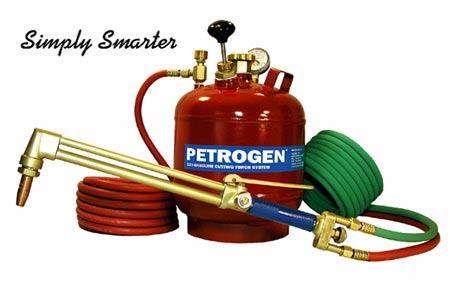
1 PETROGEN Oxy-Gasoline Cutting System the liquid fuel torch REFERENCE MANUAL First in safety and power!
2


 and not contaminated with")
. Red to gasoline (left hand thread).")


3 GETTING STARTED oxygen backflash arrestor 3 Install oxygen backflash arrestor between torch and oxygen hose. No need for a fuel line backflash arrestor. Fill tank only at a gasoline station. Gasoline must be fresh (not over 4 months old) and not contaminated with oil or diesel fuel. Low-octane fuel works fine. Attach hoses. Green to oxygen (right hand thread). Red to gasoline (left hand thread). Pump tank to 20 psi. Pressure drops as torch cuts. When it drops to 10 psi, pump back to 20 psi. Fast flow safety valve needs 10 psi to function Open tank gasoline valve slowly, about 2 turns. After 30 seconds, open valve fully. If gasoline is shut off by fast flow valve, close valve, tap tank on the ground and repeat. 7 Select cutting tip and oxygen pressure from cutting chart on gasoline tank. Open oxygen bottle valve slowly and fully. Set desired pressure on oxygen regulator. 8 Purge oxygen line by depressing cutting lever for 5 seconds. Failure to do this may create conditions for oxygen backflash. 9 Open torch oxygen valve about 1/2 turn. Final opening depends on tip size and oxygen pressure. Open torch gasoline valve until light mist appears. If liquid drips from torch, increase oxygen or reduce gasoline. Purge oxygen line again by depressing cutting lever for 5 seconds. 10 Ignite torch by striking spark close to the tip and to one side. A new hose contains air which extinguishes the flame. Just light again - about 2 or 3 times until line is purged of air. 11 Warm tip by pressing it to steel at an angle. Adjust gas valve until the steel turns a bright red orange. inner blue core lt. blue canopy orange at the end of secondary flame Final adjusted flame should have an inner blue core about 3/16-inch long (4-5 mm). Important Note: New gasoline hose contains an oily residue from manufacture that causes the flame to run yellow for about 10 minutes. Longer hoses take longer for this residue to clear. 12 When finished cutting, shut down torch by closing gasoline first, then oxygen.
4 PETROGEN OXY-GASOLINE CUTTING SYSTEM THE LIQUID FUEL TORCH CALL US IF YOU NEED ASSISTANCE. If you need help, we want to hear from you! Telephone: Toll Free: TORCH ( ) Fax: * IMPORTANT INFORMATION Fill the PETROGEN tank with fresh gasoline from a gasoline station. Fuel from other storage tanks is often old and/or contaminated and can make the PETROGEN flame run yellow. If the preheat flame burns yellow: 1. Tip may be too cool. Warm the tip by pressing it to the steel. 2. Flame may be too rich in gasoline. Increase oxygen or decrease gasoline. 3. Flame may be too large. Reduce deep blue core of flame to 1/8 inch (3-4 mm). 4. A new gasoline hose contains an oily residue from the manufacturing process which causes the flame to burn yellow. It will disappear in about 10 minutes for each 20 feet of hose. 5. Gasoline may be contaminated with oil. Get new fresh gas. 6. Oxygen supply may be insufficient. If the flame goes out while cutting: It might still be burning inside the tip. Stop the burning by quickly shutting off the preheat oxygen, and then just as quickly opening it up again. Re-light the torch. There is no danger, but you might ruin the tip if you don t act quickly. If the tip nut gets loose: Do not tighten the tip nut while the torch head is hot. If the torch head gets hot, the tip nut sometimes becomes loose. Tightening while the brass is hot might distort the head. Expansion of gasoline inside the cutting tip makes the tip run cool, but exposing the torch head to a very hot environment can overcome the cooling effect and the head can get hot. This heat can expand the brass in the torch head so that the threads pull away from the threads on the tip nut. The tip nut may loosen and the torch will pop and leak. Cool the head before tightening. The head can be cooled rapidly by closing both valves, then opening only the gasoline valve. The hot tip will vaporize the gasoline instantly and cool the tip. When the vapor turns to a mist the head is cool and the tip nut can be tightened. (To keep the torch cool, take advantage of PETROGEN s long coupling distance, described below.) You can lift the tip high above the steel and still keep cutting: You can back away from emerging slag and heat concentrations because of the gasoline flame s long coupling distance. The PETROGEN torch does not need to be precisely 1/4 away from the steel to continue cutting, as other torches do. Keep the tip out of the hot spots and you will Increase tip life and prevent overheating of the torch head. You can bury the tip in mud, sand, water, etc.: The flame might go out but will never backflash. The flame is very forceful because the gasoline in the tip expands 160 times when it changes from liquid to vapor. You are safe: 1. The PETROGEN torch cannot backflash up the gasoline line. Liquid gasoline does not burn. 2. Any leak would leave a wet spot, would be visible and could be fixed quickly. 3. If the gasoline hose is cut, the fast flow check valve in the tank shuts off the fuel.
 PETROGEN, Inc. P.O. Box 75610 Colorado Springs, CO 80970-5610 Tel: (719) 596-1175 Fax: (719) 596-4721 E-mail: torch@petrogen.")
5 Contact us with questions at any time. We want to hear from you! Toll Free (U.S.): TORCH ( ) PETROGEN, Inc. P.O. Box Colorado Springs, CO Tel: (719) Fax: (719) Website: Made in the U.S.A.
6 PETROGEN Oxy-Gasoline Cutting System the liquid fuel torch Congratulations. You now have the best oxy-fuel cutting torch for even the toughest steel cutting jobs. The major cost savings, safety and great performance that PETROGEN provides are now yours. Since the PETROGEN torch uses liquid fuel, it requires a slightly different lighting and flame adjusting process than you would use with traditional compressed gas torches. Please read the information provided in this manual, especially the section Instructions for Initial Use, to familiarize yourself with the simple techniques required for PETROGEN use. With a little practice you will be making cuts with ease that would be impossible with any other torch. This manual provides in-depth information on maintenance and repair, optional equipment, parts and other useful facts about the PETROGEN System. Please retain this manual with your PETROGEN unit. Let us know if you have any questions or suggestions about our products. We always invite your comments, and we guarantee your complete satisfaction. Milt Heft General Manager torch@petrogen.com Web site: Toll-free: TORCH
7 CONTENTS SAFETY INSTRUCTIONS page 2 STANDARD PACKAGE CONTENTS page 4 HEAVY RESCUE UNIT page 6 PORTABLE CUTTING SYSTEM page 7 INSTRUCTIONS FOR INITIAL USE page 8 QUICK REFERENCE GUIDE page 11 SAFETY FEATURES page 14 PERFORMANCE page 15 HINTS ON CUTTING page 18 OPERATING COSTS page 21 MAINTENANCE & REPAIR page 24 TROUBLE-SHOOTING page 28 OPTIONAL EQUIPMENT page 36 PARTS LIST & DRAWINGS page 42 PARTS DESCRIPTIONS page 51 APPENDICES A: FUEL COMPARISONS page 55 B: ENERGY CONSERVATION ANALYSIS page 56 INDEX page 57 1
8 1 IMPORTANT SAFETY INSTRUCTIONS (SAVE THESE INSTRUCTIONS) IMPORTANT: NEVER USE PARTS OF ANY OTHER SYSTEM TOGETHER WITH ANY PETROGEN UNIT. THAT WOULD COMPROMISE THE SAFETY OF THE PETROGEN SYSTEM. The PETROGEN System is unique. Torch, Tank, Tips and Gasoline Hose comprise the System. All parts must be used together. GASOLINE SOURCE. The PETROGEN tank should always be filled at a gasoline station pump where all safety regulations for gasoline handling are observed. TORCH OPERATION. PURGE THE OXYGEN LINE FOR AT LEAST 5 SECONDS BEFORE IGNITING THE TORCH. Because we want to provide the safest torch in the industry, we include an oxygen backflash arrestor with each torch. However, even with the use of a backflash arrestor there is no substitute for adequately purging the oxygen line before lighting. We strongly urge that operators purge the oxygen line thoroughly, as is recommended by all other torch manufacturers. (The PETROGEN torch cannot backflash up the fuel line, so no backflash arrestor is required for the gasoline line.) ALWAYS KEEP GASOLINE TANK PRESSURE ABOVE 10 PSI WHEN OPERATING THE TORCH. (Above the red zone on the gasoline tank pressure gage.) This ensures that the fast-flow check valve will operate in case of gasoline hose rupture. WHEN YOU LIGHT UP: Purge the oxygen hose by depressing the oxygen lever for at least 5 seconds. Open the pre-heat oxygen first about 1/2 turn. Then open the gasoline until you see a light mist. You should never see dripping gasoline while operating the torch. Purge the oxygen line again. The torch is now ready to be lit. (See Instructions for Initial Use for more details.) SHUTTING DOWN THE TORCH. Close the torch gasoline valve first. Then close the torch pre-heat oxygen valve. Make sure the gasoline tank filler cap is closed. Check that the gasoline tank shut-off valve is closed. Leave the tank, torch and hose connected for storage to avoid gasoline spillage. After you close all the valves, check to make sure there is no wet spot that would indicate a leak that should be fixed. An important safety feature of the PETROGEN System is the visibility of a liquid fuel leak. 2
9 SPARKS. Always use protective clothing, shoes and safety glasses when using the PETROGEN torch. Although the sparks produced by the PETROGEN cutting process are light weight and without much heat because the flame is 100% oxidizing, we recommend the use of full personal safety equipment when cutting steel. STORAGE. Storage of the PETROGEN gasoline tank should comply with all local regulations that apply to your facilities. TESTING THE FAST-FLOW CHECK VALVE IN THE TANK GASOLINE SHUT-OFF VALVE. All shut-off valves are factory tested. To understand how it operates, we suggest that you test it as follows: 1. Put gasoline in the tank. 2. Remove the gasoline hose from the tank fitting. 3. Pressurize the tank to 10 p.s.i. (at the edge of the red zone). 4. Take the tank to an area where a small amount of gasoline spillage will not be hazardous (approx. 2 tablespoons). 5. Open the gasoline shut-off valve as quickly as you can. This will activate the ball check and stop the flow of gasoline. 6. Reset the check valve by closing the shut-off valve. Tap the tank on the ground to shake down the ball check. WARRANTY If any PETROGEN product is found to be defective in materials or workmanship, PETROGEN will repair or replace that product without charge. PETROGEN may require that the product be returned to the factory for examination. Return transportation charges will be for the customer s account; replacement transportation charges will be for PETROGEN s account. This warranty is without time limit. 3
 Gasoline tank of 2.5 gallons 2 Cutting tips, sizes of your choice (See tip chart next page.")
10 2 STANDARD PACKAGE CONTENTS As you unpack your PETROGEN Standard Package Part 100 you will find the following items included: * Torch, 20 inch with 90 degree head (Other torch sizes are available.*) Gasoline tank of 2.5 gallons 2 Cutting tips, sizes of your choice (See tip chart next page.) Gasoline hose assembly, 20 feet Oxygen hose assembly, 25 feet Oxygen backflash arrestor Parts kit (part 4002) Tool kit (part 4003) Spark striker Reference Manual Getting Started color chart Training Video Torches can be provided with any combination of the following torch lengths and head angles: Torch lengths: 14, 20, 27, 36 and 48-inches. (Longer lengths can be made to order.) Head angles: 75, 90 and 180 degrees. Part 100/50 - Standard Package with 50 ft. gasoline hose and 50 ft. oxygen hose. Part 100/100 - Standard Package with 100 ft. gasoline hose and 100 ft. oxygen hose. (Other hose lengths can be made to order.) 4
11 CUTTING TIP SELECTION CHART Tip No. Inches of Steel 0 0-1/4 1 & 81* 1/ & 83* * Scrapping Tips 81 and 83 have the cutting capacity of 1 and 3 tips respectively, but the preheat of an 8 tip. Used for fast ignition on dirty or heavily rusted steel. L Heating tip R Rail cutting tip CONTENTS OF PARTS KIT: mixer with wick and O-rings pre-heat oxygen valve high pressure oxygen valve external O-ring for high pressure oxygen valve internal O-rings for high pressure oxygen valve installation tool for internal O-rings lever nut lever screw 2 metal wicks 1 set O-rings for mixer filler cap gasket leather pump cup flat seal for pump check valve extra flint for sparker CONTENTS OF TOOL KIT: tip shell reamer tip brush jack screw packing nut wrench hex allen wrench tip drill set 5

12 3 HEAVY RESCUE UNIT Heavy Rescue Unit 6050 contains: 27 inch 90 degree torch Part 6050 is recommended for extensive steel cutting in a heavy rescue situation. 2 cutting tips (81 & 83) Petrogen 2.5-gallon fuel tank 50 foot gasoline hose 50 foot oxygen hose Spare parts kit Tool kit Oxygen backflash arrester Spark striker Reference Manual Getting Started color chart Training Video The following optional equipment is recommended for use with Part 6050: Part No Optional Heavy Rescue Auxiliary Package: #5 Cutting tip Oxygen regulator, part no quick disconnects, gas, part no quick disconnects, oxygen, part no Petrogen hand cart, part no


13 4 PORTABLE CUTTING SYSTEM (PCS) PCS Part 6000 contains: Plastic carry case, with harness, scabbard, handle 20 inch 90 degree torch 3 cutting tips: 81, 83 & 5 Part 6000 PCS is recommended for short-term steel cutting where portability is important. We can furnish all items, including the oxygen cylinders. 20 foot gasoline hose 20 foot oxygen hose 2 quart gasoline tank 2 gasoline quick disconnects Oxygen backflash arrester 2 oxygen quick disconnects Spare parts kit Tool kit Spark striker Protective shaded glasses Welding gloves Adjustable wrench Pigtail for filling CGA 540 industrial oxy bottles Adaptor for filling and using CGA 870 medical oxygen bottles CGA 540 industrial oxygen bottle CGA 540 industrial oxygen regulator Loaded weight is 45 pounds. Cutting time is limited by oxygen supply. The 23 cu. ft. oxygen bottle permits continuous cutting of 1/4-inch steel for about 25 minutes, 1-inch steel for 13 minutes, or 4-inch steel for 5 minutes. If you run short of oxygen you can substitute your normal medical oxygen bottle (Jumbo D) which has the standard CGA 870 valve. Your medical oxygen bottle can be filled and used with the torch system by installing the included adapter between the medical bottle and the industrial oxygen regulator. See detailed instructions included with the PCS unit. Part No. 6000E contains all of the above items except for: Glasses, part no Gloves, part no Adjustable wrench, part no Filler pigtail CGA 540, part no CGA 540 industrial oxygen bottle, part no
14 5 INSTRUCTIONS FOR INITIAL USE These instructions will guide you through your initial set-up of the PETROGEN System. Please read these instructions all the way through before lighting up the torch. Because PETROGEN uses liquid fuel, lighting the torch and adjusting the flame require different techniques than are used with compressed gases. After you are thoroughly familiar with this start-up information, use the Quick Reference Guide on page 11 for fast reference. System Set-up 1. Unpack your system, and check each piece against the packing slip to ensure that you have received all components. 2. Take the tank to a national brand gasoline station. Unscrew the filler cap. Fill the tank with 2.5 gallons of regular grade gasoline. Never use gasoline that might be old or contaminated. Leave 2 inches (5 cm) of air space so that you can pressurize the tank. Ethanol added to gasoline in the amount set by federal regulations will not interfere with torch operation. 3. You will notice that there is no regulator on the tank as there is with acetylene. Instead, the PETROGEN system has a built-in hand pump and a pressure gage on the tank. Pump up the gasoline tank pressure to 20 psi using the hand pump on the tank. When the pressure goes down to 10 psi, pump back up the 20. Never work with tank pressure lower than 10 psi. This ensures that the fast flow check valve will function if hose is ruptured. 4. Select a cutting tip according to the Cutting Tip & Pressure Chart decal on the gasoline tank. (Chart is also on page 13 of this manual.) Install the tip and tighten the tip nut to about 15 foot-pounds. 5. Connect the red and green hoses to the torch. Connect the other end of the green hose to the oxygen regulator. Use a high-flow regulator. Connect the other end of the red hose to the gasoline tank valve. All torch and tank valves should be closed at this point. You will notice that no backflash arrestor is needed on the fuel line. We include an oxygen backflash arrestor with the unit and recommend its use. Lighting the Torch 1. Open the oxygen bottle valve slowly and fully. On the oxygen regulator, set the secondary gage to the desired pressure according to the chart on page 11 and on the gasoline tank. 2. Open the gasoline valve on the tank about two turns. The tank has a fast-flow check valve. Opening the gasoline valve too quickly will cause the check valve to shut off the fuel flow. (If the check valve shuts off, close the fuel valve at the top of the tank and tap the tank on the ground a few times. This will reopen the check valve.) 8
15 3. Open the tank gasoline valve fully when the fuel line has been pressurized. There is now liquid gasoline running from the tank, through the hoses, to the tip in the torch head. IMPORTANT: MAKE SURE THE TANK GASOLINE VALVE IS FULLY OPEN DURING USE. This ensures operation of the fast flow check valve in case of fuel hose rupture. 4. PURGE THE OXYGEN HOSE BY DEPRESSING THE HIGH PRESSURE OXYGEN LEVER FOR AT LEAST 5 SECONDS. This purges any gasoline vapors that might be present in the oxygen line. Purging of the oxygen line is required for all oxy-fuel cutting torches. 5. Open the pre-heat oxygen valve on the torch about 1/2 turn. Final setting depends on tip size and oxygen pressure selected. 6. Open the torch gasoline valve at the butt of the torch SLOWLY until you see a light mist. There should never be any gasoline dripping from the torch. If gasoline drips, increase the pre-heat oxygen or decrease the gasoline. 7. Purge oxygen line again. 8. Strike a spark very close to the tip and to one side to ignite the mixture. Don t hold the sparker for too long in the mist or it will get wet and will not light. On first use, new gasoline hose contains air which must be bled out. An air bubble may extinguish the flame 2 or 3 times before the line is bled. After the bubble passes through the tip the mist will appear again. Light the mist and wait for the next air bubble. When flame is steady, then the pre-heat flame can be adjusted. This process needs to be done only when first starting up or after the hose has been emptied. Note: New gasoline hose may contain oily residue from the manufacturing process. It may cause the flame to be yellow for the first 5 to 10 minutes after lighting until the residue is cleaned out of the 20-foot hose. Longer hoses will need more time to clear this residue. Flame Adjustment 1. When the torch is lit, do not attempt to adjust the flame but immediately press the tip to the steel surface at a slight angle for about 4 seconds to heat the tip. This warms the tip sufficiently to vaporize all the gasoline passing through. There is no danger of backflash up the fuel line with the PETROGEN torch as there is with acetylene, because the liquid fuel will not allow a flame front to enter the torch. 2. With the tip still pressed to the steel, adjust the flame by opening and closing the torch gasoline valve. Watch the steel react to the flame as the mixture changes. When the steel reacts with the brightest orange and red color, then adjustment is optimum. The final blue flame should be 3/16 inches long. 9
16 3. Another test for a properly adjusted flame is to press the tip to steel at a slight angle and get an orange sunburst with the rays about 2 inches long, again with the steady, mild roar. FLAME PATTERNS Too Little Gasoline Balanced Flame Too Much Gasoline * no canopy * canopy * canopy * hissing sound * roaring sound * wavering blue core * flame about to * dark blue core * streaking yellow separate from tip 3/16 (4 mm) Smaller pre-heat flames give sharper kerf edges. Larger pre-heat flames may permit faster cutting. We recommend the blue inner core of the flame be 3/16-inch (4 mm). A properly adjusted pre-heat flame will result in very fast ignition of the steel. With experience, warming the tip and adjusting the flame can be done at the same time in just a few seconds. Note on Setting Pressures: Follow the Cutting Tip & Oxygen Pressure Chart carefully at first. Although these suggested oxygen and gasoline pressure settings have a great deal of flexibility, too much divergence from recommended pressures will result in unacceptable performance. Shutting Down 1. Close the torch gasoline valve first. 2. Then close the torch pre-heat oxygen valve. 3. After the torch is shut down, check to make sure the tank filler cap is closed and the tank shut-off valve is closed. Leave the tank, torch and hose connected for storage. If fuel lines must be disconnected, quick disconnects can be used so that the fuel line does not need to be bled each time the torch is used. 10
17 46 QUICK PETROGEN REFERENCE GUIDE To Light & Adjust 1. Select tip and set oxygen tank pressure according to the Cutting Tip & Pressure Chart on page 13. (Chart also found on the PETROGEN tank.) 2. Pump gasoline tank pressure to 20 psi. 3. Open gasoline tank valve slowly at first so that the fast-flow check valve does not seat. Then open fully 4. Purge oxygen hose for at least 5 seconds by depressing the cutting lever. 5. Open torch oxygen valve about 1/2 turn. 6. Open torch gasoline valve until fine mist appears. No drops. 7. Purge oxygen line again. 8. Strike a spark close to the tip slightly to one side. 9. Press tip to steel for about 4 seconds to warm it. 10. Adjust the flame by opening and closing gasoline valve until steel reacts with the brightest orange and red color To Shut Down 1. Shut torch gasoline valve first. 2. Then close torch oxygen valve. 3. Check to make sure tank filler cap and tank shut-off valves are closed. 11


18 6 7 Open torch gasoline valve until light mist appears. Purge oxygen line again. 1 Select tip and set oxygen pressure according to the chart on page 13 and on the tank Open torch pre-heat oxygen valve approximately 1/2 turn. Purge oxygen line by pressing cutting lever for 5 seconds. Strike spark close to the tip and slightly to one side. Press tip to steel and adjust gasoline valve until steel reacts with brightest orange-red color. 10 Make final flame adjustment so that dark blue flame core is about 3/16-inch long with light flame canopy around it Slowly open tank shut-off valve 2 turns. Then open fully. Opening too fast can activate fast-flow check valve. Pressurize tank to 20 psi.
19 CUTTING TIP & PRESSURE CHART ENGLISH METRIC INCHES TIP POUNDS/INCH 2 MM. TIP KPA STEEL NO. GASOLINE OXYGEN STEEL NO. GASOLINE OXYGEN 0-1/ /4-1 1 & & & & This chart shows the cutting range of each tip, and suggests gasoline and oxygen pressures. The range of each tip can be extended by higher oxygen pressures, but quality may be reduced. A decal of this chart is on every PETROGEN tank. The best combination of tip and pressures depends on operator technique, type and size of steel, desired cutting speed and quality of cut. A good operator will keep oxygen pressure as low as possible and still do the job well. These gasoline pressures are minimum. We recommend pumping to 20 psi, then allowing pressure to drop to 10 psi before pumping again. Never work with tank pressure less than 10 psi. The fast-flow check valve needs 10 psi to operate properly. When operating, keep the gasoline shut-off valve fully open to ensure proper operation of the fast-flow check valve. 13
20 57 SAFETY FEATURES PETROGEN is the safest oxy-fuel system ever built. Its design eliminates every major danger associated with acetylene and propane use. Cannot backflash up the fuel line. The gasoline is liquid right up into the cutting tip. Liquid gasoline can not burn. It is not possible to have a fire in the fuel line. Fuel leaks can be detected. Fuel from any leak, pinhole, or open valve can be SEEN and corrected. Only low pressure needed in the tank. Tank pressure of psi is all that is required. The purpose is only to deliver the gasoline to the cutting tip. Inside the cutting tip the gasoline expands from liquid to vapor, resulting in a volume expansion of 160 times. It is this expansion which gives force to the pre-heat flame and makes it very difficult to extinguish the PETROGEN flame. Fast flow check valve in the tank shuts off the fuel in case of a fuel hose rupture. A cut hose results in a surge of fuel flow, which activates a floating ball check in the gasoline outlet valve. The ASME code gasoline tank has a pressure relief valve which opens at 35 psi. A Petrogen tank caught in a fire will vent off the vapor coming from the heated gasoline inside. The liquid gasoline inside the PETROGEN tank is inert and will not respond to heat or shock. An acetylene tank caught in a fire is a latent bomb. Check valves in the tank prevent gasoline spillage. There are check valves under the pressure gage and inside the outlet valve that activate in case the gage or valve are accidentally broken off. Tips and torch heads run cool. The gasoline evaporates in the tip which makes the tip a refrigerator. Tips and head run much cooler than any other torch, presenting reduced hazard to the operator. Tips resist melting to a great degree, adding to long tip life. Sparks are cool and light. Gasoline is 100% oxidizing to steel. The steel is completely burned out and the sparks have little weight or heat, resulting in reduced hazard. Acetylene is only 70% oxidizing, leaving 30% of the steel molten, heavy and hot. Safety Certifications Listed by Underwriters Laboratories Tested and Recommended by the U.S. Dept. of Energy Safety Certified by: - U.S. Navy - U.S. Coast Guard - Lloyd s Register of Shipping - GS Certificate (BAM, Germany) Deemed suitable by MSHA for use in all mines, including underground coal mines 14
21 68 PERFORMANCE The PETROGEN system out-performs all other oxy-fuel systems, cutting faster, cleaner and more efficiently. Many jobs you could not do with other torches PETROGEN will do quickly and safely. Here is the kind of performance you can expect from your PETROGEN torch: Cut steel faster: PETROGEN cuts 2 to 4-inch steel twice as fast as acetylene, and up to 4 times faster than acetylene in the to 8 to 10-inch range. In thin steel up to about 1/4-inch, PETROGEN will cut at about the same rate as acetylene, but will not be slowed down by most surface contamination. Because the oxy-gasoline flame carries the heat deeper and faster into the steel, you can make these cuts: 4-inch shaft in 30 seconds, 6-inch shaft in 90 seconds, 12-inch shaft in 3 minutes, punch a straight hole through a 10-inch shaft in one minute. Work more efficiently: Burners have greater freedom of movement and positioning while using the torch because it cannot backflash up the fuel line, even if the tip is pressed onto the steel surface or into the ground. Also, the torch produces less harmful sparks for burners to contend with. The 100% oxidized slag is light weight and carries much less heat than acetylene slag. Cut layers: To cut stacked plate, the starting edges should be lined up as evenly as possible and ignition should be obtained down the entire stack before attempting to move into the cut. After total ignition is obtained, the cut proceeds at almost the same speed as cutting a solid piece of steel. Wire rope is cut easily. Cut across air gaps: The PETROGEN torch has the amazing ability to bridge multiple gaps up to 1/2 inch each, and even larger single gaps. Measure the height of the stacked plate and consult the cutting chart. Select the next larger size tip. Sometimes the second or third larger tip must be used. For example, 18 layers of stacked 1/4 inch (6 mm) plate measuring 7 inches (18 cm) are cut nicely with a no. 7 tip at 90 pounds (630 kpa) oxygen. Long coupling distance: The flame has a large coupling distance. The tip can be raised high above the steel surface and still keep cutting all the way through the steel. No grinding: The PETROGEN flame oxidizes the steel 100% so there is no molten steel in the slag. Cuts are clean and never need grinding. (Acetylene oxidizes only 70% of the steel. That means 30% remains as molten steel to re-form on the steel surfaces.) Punch holes: The PETROGEN system can blast through 10 inches of armor plate in 50 seconds. Oxygen pressure is critical in punching holes. Not only must cutting proceed down into the hole, but there must be enough oxygen 15
22 pressure to blow the slag back out through the top until the hole is blown through. Up to 3+ inches (8+cm) of steel is easily punched with a no. 3 tip at pounds (420 kpa) of oxygen. Deeper holes require at least one tip size larger than normal and also need higher oxygen pressures. The problem increases rapidly with the increasing depth of the hole. Maximum capability is a 10 inch (25 cm) hole blown with a no. 8 tip at 140 pounds (980 kpa) oxygen. Too much oxygen may cool the steel to the point where ignition is lost. To start the hole: When you see some steel begin to melt, press the cutting lever slowly. As the molten slag comes out of the hole, move the tip carefully towards you so that the slag is ejected opposite from you. Then press the cutting lever fully. This will result in the burning slag blowing away from you, and keeps you free of sparks. Hold the torch steady in this new position. Lift it vertically if you see slag building up towards the tip. Do not let the tip enter the hole. The hole will proceed to burn directly downwards. Contaminated steel surfaces: PETROGEN s totally oxidizing flame burns and blows steel clean, even when covered with dirt, rust, paint or barnacles. The steel is cleaned and cut with the same pass of the torch. For maximum speed through a contaminated surface, we recommend our 81 or 83 tip. See page 51 under high heat scrapping tips for more information on these tips. Concrete-backed steel and rebar: With conventional torches, cutting into steel that is backed with or embedded in concrete results in explosions and molten-steel spray that makes this work dangerous. PETROGEN does the job smoothly and quickly without any popping. Stainless-backed steel: Because of PETROGEN s total oxidation, deep penetration, and fast heat release, mild steel backed with stainless steel is cut without difficulty. What it doesn t cut, it melts. Sheet piling: Interlocking sheet piling often must be cut horizontally after being driven to desired depth. Cutting across the knuckle joint presents a problem that is formidable for most torches, but easily solved by PETROGEN. One common sheet piling system has knuckle joints that are about 3 inches thick. The joint consists of 3 layers of steel separated by 2 layers of very difficult dirt, gravel, mud, etc. The PETROGEN no. 5 tip at 60 or 70 pounds oxygen will continue its cut right across this joint with only a nominal drop in speed. A slight sawing motion may be required to maintain ignition. Alloy steels: Some alloy steels can be cut with PETROGEN. For example, manganese steel such as used in high quality dipper teeth and cutting edges yields easily to PETROGEN. Low grade stainless steel with up to 10% nickel or 5% chrome also yields. Cast irons come in many formulas; the PETROGEN torch cuts some types easily, some with difficulty, and some not at all. A general rule of thumb is that whatever an acetylene torch might do against a cast steel or iron, PETROGEN can do better. Larger tips and higher pressures may be needed in some cases. Galvanized steel: Toxic fumes are generated by cutting galvanized steel. With other cutting systems, these fumes are heavy, dark and ominous, but with 16
23 the PETROGEN system the fumes are enormously reduced. Breathing protection is of course still recommended. Cut under water, mud, dirt: The powerful flame resists being extinguished, even in water, mud and dirt. It can cut into a pressured water pipe and keep on cutting. The PETROGEN torch can be adapted for underwater cutting with a special tip and shroud. Hot and cold weather: Hot weather use is not a problem. In fact, if the weather is very hot, PETROGEN will be able to make cuts using diesel fuel. Cold weather is not a problem. In sub-freezing temperatures it may take more than the normal 4 seconds to warm the tip, but there is no general interference with operation. Tips run cool, do not clog: Because there is no molten steel in the slag, tips will never clog and can last for years with reasonable maintenance. There is a refrigeration effect in the torch head as the gasoline evaporates in the tip. Head and tips run much cooler than other torches. Cut with 90% pure oxygen: PETROGEN is the only oxy-fuel torch that can cut steel with impure oxygen produced by oxygen generators using the nitrogen adsorption process. These generators can produce oxygen 24 hours a day, and bottles can be filled for delivery to remote work sites. If you are interested in this type of oxygen generator, contact us for the names of suppliers. Liquid oxygen: PETROGEN performs the same, regardless of the oxygen source. However, the smaller sizes of liquid oxygen bottles have a rather low limit to the amount of oxygen that can be passed, about 300 Standard Cubic Feet per Hour (SCFH). To get more oxygen from a liquid source, see your oxygen supplier. Note: The PETROGEN torch cannot be used for welding because of its 100% oxidizing flame. This complete oxidation of steel is what makes PETROGEN a superior cutting tool. 17
24 79 HINTS ON CUTTING Igniting the Torch Gasoline is hard to ignite. That helps make it a safer fuel, but it also requires a little practice on igniting technique. First open the pre-heat oxygen valve about 1/2 turn, then open the gasoline valve until you see a fine mist. (You should not see drops.) Do not hold the sparker directly in front of the tip. It will get wet with gasoline and will not spark. Instead, hold the sparker to one side, but very close to the end of the tip. At the same time you make a spark, move the sparker into the mixture, throwing the spark into the stream. If there is not enough gasoline, striking the spark will not ignite the torch because the oxygen will blow the gasoline mist away. If there is too much gasoline, striking the spark will result in a flame that is too yellow and possibly dripping with excess fuel. The correct valve settings depend on the tip size and the oxygen pressure. With experience, you will know from sight and sound when the mixture is in proper balance and of proper volume. Warming the Tip Before doing anything else after lighting the torch, warm the tip. Do not try to adjust the flame until the tip is warm. When the tip is cold, gasoline is not completely vaporized and the flame has many yellow rays. After the tip gets warm, the gasoline is completely vaporized inside the tip and the flame becomes blue. To warm the tip, ignite the flame and lightly hold the tip against a piece of steel at a slight angle. (In the very large tip sizes just hold the tip close to the steel without touching.) In about 4 seconds, lift the tip and the flame should be devoid of yellow. If yellow is still there, warm the tip again for 8 seconds. If heavy yellow persists, reduce the gasoline flow or increase the oxygen flow and warm again. If you cannot eliminate the yellow, the gasoline may be contaminated or old. Fill the tank with regular grade gasoline from a national brand station. A slight trace of yellow at one side usually means a small particle of dirt. To clear the dirt, hold the tip flat against the steel and raise the side where the yellow trace originated. Adjusting the Pre-heat Flame The pre-heat flame must be visibly enriched with fuel. An oxy-acetylene adjustment is too lean. A properly adjusted pre-heat flame will result in very fast ignition of the steel. Adjust the flame by holding the preheat oxygen valve open at 1/2 turn. While holding the tip on the steel, open and close the gasoline valve until the steel reacts with the brightest orange and red color. This is the well balanced flame. Make readjustments in order to bring the length of the dark blue flame to 3/16 inch. 18
25 The most common mistake is a flame too lean. If there is no canopy and the flame has a hissing sound instead of a roar, then increase the gasoline. Smaller pre-heat flames give sharper kerf edges. Larger pre-heat flames may permit faster cutting. A balanced pre-heat flame can be achieved at all levels of power. With experience, warming the tip and adjusting the flame can be done at the same time in just a few seconds. Setting Pressures There is a decal chart on the gasoline tank giving tank and oxygen pressures for steel thickness and tip sizes. The same chart is on page 13 of this manual. Follow the pressures given in this cutting chart carefully at first. Although each suggested setting has a great deal of flexibility, too much divergence from recommended pressures will result in unacceptable performance. Gasoline Tank Pressures: The listed gasoline pressures are minimum. We suggest pressuring the gasoline tank to 20 psi and then pumping up again when pressure falls to the minimum (10 psi). Never work with tank pressure lower than 10 psi. Gasoline pressures are not critical. A need for more gasoline pressure becomes obvious when opening the torch gasoline valve does not produce any effect. THE PRESSURE GAGE MUST READ OUT OF THE RED ZONE. This will ensure operation of the fast flow check valve in the tank. Elevation: Gasoline pressure at the torch is affected by elevation above the tank. When the difference in elevation approaches 30 feet, compensate by increasing the tank pressure. Above 30 feet, either take the tank with you or install the tank automatic pressure kit (part no. 2349), to be used with the compressed air carry tank (part no. 2365). Oxygen Pressures: Oxygen pressure requirements are more complicated than gasoline pressures. The cutting chart is a good place to start, but final oxygen pressure depends on the steel, surface conditions, thickness, operator technique, desired speed, desired quality, and many other factors. Cutting Speed The powerful PETROGEN torch cuts faster than an acetylene torch. The higher speeds are more obvious as the steel becomes thicker. In 1-inch steel PETROGEN cuts 20% faster. In 2 to 4-inch steel PETROGEN cuts twice as fast. In 10-inch steel PETROGEN cuts 4 times faster. There are several reasons for this greater productivity: 1) The acetylene flame is only 70% oxidizing, leaving 30% of the cut steel to freeze to solid again. The gasoline flame is 100% oxidizing, leaving a clean cut with no chipping or grinding required. Cutting is actually a burning or oxidizing process and the 100% oxidizing nature of the gasoline flame greatly assists the cutting process. 19
26 2) Gasoline vapor is 4 times heavier than acetylene vapor. With the pre-heat flame lit, pressing the cutting oxygen lever reduces oxygen supply to the preheat flame. Therefore, some of the gasoline vapor remains unburned in the pre-heat flame but travels down into the cut with the cutting jet oxygen. As the fuel travels down the jet it continues to burn, giving off more heat while deep into the cut. With acetylene this secondary combustion is limited to about 2 inches, but with the heavier gasoline fuel, secondary combustion goes deep into the steel. Cutting with gasoline is like cutting with the long edge of a hot knife. 3) The oxy-gasoline flame temperature is 5200 degrees F. The gasoline flame releases its heat energy faster and heats the steel faster than acetylene. Though the acetylene flame is slightly warmer (5600 F), it is the gasoline flame that brings steel to ignition faster and continues to cut faster. PETROGEN does not issue a chart of cutting speeds. It is our opinion that speed charts are inaccurate at best and misleading at worst. In any given situation, cutting speed depends on many variables: type of steel; thickness of steel; surface conditions; size of cutting tip; size of pre-heat flame; oxygen pressure; operator skill; quality of cut; torch hand-held or machine mounted. A change in any of these variables will have a large effect on final speed, but may also have several other effects as well. For example, using a larger tip may increase speed, but will also significantly increase oxygen consumption and may have an adverse effect on quality. Operator skill must be tuned to obtain maximum speed at desired quality with minimum oxygen consumption. 20
27 10 8 OPERATING COSTS The cost of doing a certain amount of cutting is the cost of: Fuel + Oxygen + Labor + Maintenance. Fuel: Gasoline is the cheapest fuel, except for natural gas used in permanent installations. The cost of fuel can be expressed in terms of cost per BTU, because the quantity of steel cut by any fuel is directly proportional to its BTU content. One gallon of gasoline does the work of 100 cubic feet of acetylene. All pure hydrocarbon fuels have about 21,000 BTU s per pound, so relative costs are in the same proportion as relative weights. In the United States, gasoline is about 90% cheaper than acetylene and about 50% cheaper than propane. The low cost of gasoline is just the first of several savings that can be credited directly to fuel. If the job shuts down because the acetylene or propane supplier fails to deliver fuel on time, the cost of an entire day s production can rightfully be charged to fuel. Gasoline, on the other hand, is delivered by the best fuel distribution system in the world and can be obtained anywhere, any time. It is probably available in the truck that took the work crew to the work place. Additional fuel costs chargeable to acetylene are cylinder delivery and demurrage charges. Accidents from handling the very heavy acetylene tanks can also be charged to fuel, and also accidents from acetylene backflashes can be considered as fuel costs. Oxygen: In any fuel system, oxygen is a significant cost and its consumption must be watched and controlled. Oxygen consumption is largely under the control of the operator. An unskilled operator can easily use 2 or even 3 times as much oxygen as necessary. (See Oxygen Consumption below.) Assuming that the operator is skilled, oxygen consumption will vary among the different fuel systems. Most acetylene operators will agree that the oxygen/fuel ratio is about 3+ to 1. That is, for every 250 cubic foot bottle of acetylene, the operator will use about 900 cubic feet of oxygen. Different fuels have different chemistries of combustion, and a cost analysis must consider this. It is found that the PETROGEN system uses the same amount of oxygen as does acetylene. It is also found that the propane system uses about 25% to 30% more oxygen than does acetylene. Switching from acetylene to gasoline does not affect oxygen costs, but switching from propane to gasoline reduces oxygen costs considerably. Labor: The way to save labor cost is to increase productivity. The way to increase productivity is to increase cutting speed. If an operator doubles his production, he reduces his cost in half. The PETROGEN system is amazingly fast. Heavy steel pieces do not have to be soaked with heat before cutting. Ignition is the fastest. The clean cutting action eliminates chipping and grinding. Speed is up to 4 times faster than acetylene. The thicker the steel the faster the comparative speed of PETROGEN. Dirty or rusted surfaces that slow down other systems have less effect on PETROGEN speed. Many unusual cutting problems that materially affect other systems are easily handled by PETROGEN. 21
28 Maintenance: Maintaining a cutting torch system is relatively low cost. It does not vary much among the higher quality torches of the different systems, except for the factor of cutting tip life. The PETROGEN tip has an extraordinary long life, many serving a year or longer, even in rough daily usage. PETROGEN tips will not clog and will greatly resist melting - the 2 most common causes of tip failure. Savings can be significant. (See Long Tip Life below.) OXYGEN CONSUMPTION The PETROGEN system uses about the same amount of oxygen as the acetylene system, cut for cut. The PETROGEN tank of 2-1/2 gallons is the equivalent of the large acetylene tank holding 250 cubic feet. Both the PETROGEN tank and the acetylene tank use about 900 cubic feet of oxygen. Oxygen consumption depends on a number of factors. 1). Consider how much steel has been cut, not how long the torch was lit. The PETROGEN torch does more work in less time so a higher rate of oxygen consumption can be expected. This is offset by a speed of up to 4 times faster. 2). Select the smallest tip that does the job well. 3). Use the lowest oxygen pressure that does the job well. 4). Adjust the pre-heat flame to the smallest that does the job well. 5). Avoid unproductive time when the torch is lit but not cutting. OXYGEN CONSUMPTION CHARTS CUTTING TIPS Pre-heat and cutting oxygen both on. Cutting Oxygen Standard Cubic Tip Pressure Feet per Hour Size (psi) (SCFH) HEATING TIP Adjusted to a large flame. Heating Oxygen Tip Pressure SCFH Size (psi) L
29 GASOLINE CONSUMPTION Gasoline contains about 135,000 BTU s per gallon (one gallon of gasoline weighs 6.2 pounds). A small amount of gasoline cuts a large amount of steel. For any tip size, gasoline consumption depends solely on the size of the pre-heat flame. Adjusting from a small pre-heat flame to a large one could greatly increase gasoline consumption. The following chart is based on a reasonably-sized preheat flame (about 3/16 inch): GASOLINE CONSUMPTION CHARTS CUTTING TIPS HEATING TIP Tip Gallons of Gasoline Tip Gallons of Gasoline Size per Hour per Hour 0.30 L LONG TIP LIFE PETROGEN tips have a very long life, even with daily use in scrap-cutting operations. Proper understanding and reasonable care can result in tip life of as much as one year. Except for abuse and accident, the 2 reasons for failure of conventional tips are clogging and melting. The acetylene tip is damaged when molten steel blows back and lodges in one of the tip holes. Soon, the holes melt shut and ruin the tip. This cannot happen with the PETROGEN tip. There is no molten steel, only 100% oxidized slag. Acetylene is only 70% oxidizing, while gasoline is 100% oxidizing. 100% oxidized slag does not have enough weight or heat to lodge in the tip and damage it. The PETROGEN tip is resistant to melting because the tip is always cool. Gasoline vaporizes inside the tip and, because vaporization is a cooling process, the tip becomes a small refrigerator. This strong cooling effect gives great protection against melting. Coolness is directly proportional to the amount of gasoline being vaporized. A tip will run hotter if it is a smaller size (no. 0 & 1), if the pre-heat flame is small, or if the fuel is oily. 23
30 11 9 MAINTENANCE AND REPAIR Tools The PETROGEN unit comes with a tool kit containing the following items: Tip Reamer Hex Wrench Jack Screw Packing Nut Wrench Tip Drill Set Tip Brush 1. Tip drill set: cleans the high pressure oxygen path in the tip core. 2. Tip brush: cleans the core flutes and the shell bore. 3. Tip reamer: cleans carbon from inside the tip shell. 4. Hex allen wrench: operates the hose connectors on the torch. 5. Jackscrew: removes the mixer from the torch head. Mixer 6. Packing nut wrench: used in the following operations: a. Closed hex for operating the high pressure oxygen valve nut. b. Open hex for operating packing nuts on pre-heat oxygen valve and torch gasoline valve. Packing nut should be tightened to stop leaks, but still permit comfortable operation. Cutting Tips PETROGEN tips require very little maintenance and have an extremely long life. Regular maintenance and careful use can extend the life of tips for several years. There are 3 tools for cleaning the tip: 1. The tip drill is used to clean out the center bore of the cutting tip. This gets clogged only by dirt, never by slag. You will seldom need to use this tool. 24
31 2. The tip brush is your most important tool for good maintenance. It is used to clean the flutes of the core, the tip seat at the bottom of the core, and the inside taper of the shell where the flutes mate. A thin knife blade does an excellent job of cleaning the flutes. 3. The tip reamer is used to clean the inside section of the tip shell. Turning the reamer in the shell removes carbon deposits. Leaking and Popping Tips - A leaking tip is one that leaks gasoline past the tip nut. The gasoline ignites and flame surrounds the tip nut. A popping tip is one that pops continually, one pop every few seconds or as frequently as a machine gun. A popping tip can damage the tip, mixer, high pressure oxygen valve, and even the torch head. Do not operate a tip that pops continually. The most common cause of a leaking/popping tip is a bad fit between mixer and tip. There is both an outer and an inner seat on the 45 degree tapered surfaces. If the outer seat fails to meet, then the tip is a leaker. If the inner seat fails to meet, then the tip is a popper. There are 2 conditions that create a bad fit between tip and mixer: 1. Loose tip nut 2. Defective tip seat 1. To Fix a Loose Tip Nut: The tip nut may become loose if the torch head gets too hot. Expansion of the brass in the torch head causes the threads in the torch head to pull away from the threads in the tip nut. The tip nut takes this opportunity to loosen. Do not tighten the tip nut while the torch is hot. To cool the tip rapidly, close both torch valves. Then open the gasoline valve only. The gasoline passing through the hot head and tip will vaporize immediately and throw out visible vapors. As the head and tip cool, the vapors will turn to spray, indicating that the head is now cool enough to tighten the tip nut without damage. 2. To Fix a Defective Tip Seat: First examine the tip seat for scratches, cuts and gouges. If deep scratches exist, the seat cannot be repaired. If deep scratches are not apparent, then the seating problem can be corrected by removing a small amount of brass from either the inner or the outer seat. To correct the seating, insert the brass core of the tip into a drill press, exposing the seat. Operate the drill at about 300 RPM. To Fix a Leaking Tip: With 320 grit emery paper, press against the inner seat for about 6 seconds. Cut a thin strip of emery paper in order to avoid hitting the outer seat. To Fix a Popping Tip: With 320 grit emery paper, press against the outer seat for about 6 seconds. Insert the tip into the torch and flame test it. If it still pops, repeat the emery paper process. Cutting off too much brass will convert a leaker into a popper--or a popper into a leaker. 25
32 Carbon Build-Up - Carbon can build up inside the tip, just like the carburetor of a car. This carbon comes from gasoline that is not completely burned, the result of a flame too rich for too long. If a tip is not cleaned periodically, this carbon builds up in the shell and on the core and eventually creates further problems that can destroy the tip. Through lack of maintenance the carbon can lock the core to the shell. Then when the tip nut is removed, the twisting motion of the shell grabs the flutes of the core and twists them, ruining the core. Until you become familiar with the rate of carbon deposit in your particular torch application, it is wise to examine your tips once or twice a week. If you neglect this maintenance you can lose the tip. The core can also lock to the shell by operating the torch in extreme heat. Before removing a very hot tip it is best to cool it rapidly by opening only the gasoline valve. The hot tip immediately vaporizes the gasoline, which cools the tip. When the vapor changes to spray, the tip is cool. If the shell becomes stuck to the core, twist them apart by gently working them loose using two pair of pliers. High Pressure Oxygen Valve Broken O-ring - The symptom of a broken O-ring is a constant leak of high pressure oxygen through the cutting tip. The cause of O-ring failure is almost always a back-pop up the oxygen line. Each tool kit comes with one installation tool and 4 O-rings. If purchased separately, the parts are as follows: 1357 internal O-ring for high pressure oxygen valve 4017 installation tool for O-ring 1357 (aluminum cone) Installation procedure: 1. Remove cutting lever nut. 2. Remove cutting lever screw. 3. Remove cutting lever. 4. With packing nut wrench (part 4011) remove high-pressure oxygen valve. 5. Hold hex-nut of oxygen valve firmly with packing nut wrench; unscrew valve stem. 6. O-ring is located inside rim in valve stem; scrape clean. 7. Insert valve stem into installation cone and roll replacement O-ring onto rim as pictured here. 26
33 Torch Gasoline Valve The torch gasoline control valve is a single, one-piece stainless steel rod with the needle point machined at one end. If replacement is needed, the entire gasoline valve must be ordered. Internal Damage Requiring Disassembly at Factory Send your torch to the factory for repair for any of the following conditions: 1. Gasoline or oxygen leaks from the weep holes in the butt handle. 2. Gasoline leaks from the compression fitting at the torch butt. 3. With the gasoline valve closed, gasoline leaks from the torch head through the 2 holes normally passing pre-heat oxygen. Looking into the torch head cavity, the 2 pre-heat oxygen holes are located a little past the deep groove from where gasoline normally exits. WARNING: DO NOT TAMPER WITH THE COMPRESSION FITTING AT THE BOTTOM OF THE TORCH. Below the butt forging are 2 nuts. One nut under the handwheel is the packing nut for the gasoline valve. The other nut (tight against the butt forging) is the compression fitting that holds the torch together. This disassembly must be done at the factory. We urge you to send us your torches for this major repair. Factory Repairs The factory can repair and recondition your equipment. Contact us at the factory for return instructions. 27
34 10 12 TROUBLE-SHOOTING Problems: Miscellaneous With tank and torch valves open, no gasoline exits from cutting tip. Difficult to ignite pre-heat flame. Hard to ignite steel. Very slow cutting Tank empty. No pressure in tank. Fast flow check valve is shut. Obstruction in gasoline hose. Obstruction inside torch. Clogged wick. Mixture is too rich. Mixture is too lean. Pre-heat mixture not balanced. Pre-heat flame too small. Cutting tip not at proper distance from steel. Tip too small. Flame too small. Not enough oxygen pressure. Fill tank to within 2 inches (5 cm.) from top. Pressure tank to at least 10 psi. Close tank shutoff valve. Bounce tank sharply on ground. This should re-set check valve. Open shutoff valve slowly. With all valves open, loosen gasoline nut at torch hose connector. If gasoline exits, then obstruction is in torch. If not, then loosen gasoline nut at tank. If gasoline exits, then obstruction is in hose. 1) Remove gasoline control rod. Examine needle point for breakage. Broken point may be lodged in valve seat in head. 2) Blow out gasoline tube with air. Remove mixer. Change wick. Reduce gasoline and/or increase oxygen. Reduce oxygen and/or increase gasoline. Reduce gasoline and/or increase oxygen. Reduce oxygen and/or increase gasoline. Increase both gasoline and oxygen. Move tip closer and further from steel. Look for optimum distance where steel heats fastest. Use larger tip. Increase both gasoline and oxygen. Increase pressure at oxygen regulator. 28 Cutting tip not at proper distance from steel. Move tip closer and further from steel. Look for optimum distance where cutting speed is fastest.
35 Opening pre-heat oxygen shuts off fuel. Damaged tip. Damaged tube inside copper shell. Replace tip. Problems Prior to Lighting the Torch Gasoline leaks at compression fitting. Gasoline leaks at gasoline hose connector. Gasoline leaks at gasoline valve packing nut. Gasoline leaks from handle weep hole. Gasoline leaks in torch head from pre-heat oxygen holes. Gasoline leaks in torch head from gasoline hole. Oxygen leaks at high pressure oxygen valve. Oxygen leaks at preheat oxygen valve. Oxygen leaks in torch head from pre-heat oxygen holes. Compression fitting not seating properly at butt face. Connector not tight in butt (right-hand thread). Threads damaged. Packing nut not tight on compression fitting. Threads damaged. Internal damage: broken O-ring. Internal damage: copper gasket. Gasoline needle valve does not shut properly. External O-ring damaged. Internal packing O-ring damaged. Packing nut not tight. Pre-heat oxygen valve not seating properly. Do not tighten. Apply thread adhesive. If leak persists return to factory for internal repair. Tighten with hex allen wrench. Apply some thread adhesive. Remove connector. Chase or clean mating threads (1/4 NPT). Wrap teflon tape and reinstall. If condition persists, replace with new hose connector. Tighten packing nut until leak stops. Replace packing nut and packing. Requires internal repair. Return to factory. Requires internal repair. Return to factory. Replace gasoline valve. If not cured, return to factory for internal repair. Replace O-ring (part 1356). Replace O-ring (part 1357). Inside valve under spring. Tighten packing nut. Remove valve. Clean tip with abrasive paper. Blow out seat in torch. Re-install valve. If leak persists, close valve and tap sharply with light hammer. Try new valve. If valve seat in torch is damaged, torch should be returned for repair. 29
36 Oxygen leaks in torch head from bottom of head. Oxygen leak from handle weep-hole. Damaged O-ring in h.p. valve High pressure oxygen valve not seating properly in torch. Internal damage: O-ring. Replace internal O-ring (Part 1357). Tighten valve. If leak persists, remove valve. Remove stem. Refinish flat seat with fine abrasive paper. Blow out seat in torch. Re-install valve. Try new valve. If valve seat in torch is damaged, return torch for repair. Return to factory for internal repair. Problems While Torch is Lit Gasoline leaks at tip nut, or torch pops. Torch pops once. Flame dies but may continue inside tip. Pre-heat flame always yellow. Yellow jet flame Pre-heat flame fluctuates or dies. Bad seating inside torch head between tip nut, tip, mixer & torch head. Probably isolated occurrence. Flame exit temporarily.blocked. Mixture too rich. Gasoline polluted by oil or diesel or alcohol. Gasoline polluted by residue in new hose. Not enough oxygen. getting to tip. Cutting tip cold. Dirt in jet hole. Gasoline needle valve not seating. Air entering fuel system. Clogged wick Oxygen getting into fuel system. Mixer not seating 1.) Loose tip. 2.) Bad tip seat. Try another tip. If both tips leak or pop, replace the mixer. 1. Close pre-heat oxygen valve. 2. Quickly open again. 3. Purge oxygen line. 4. Re-ignite torch. Increase oxygen and/or decrease gasoline. Rinse tank and fill with regular grade gasoline from a national brand station. Run torch until yellow disappears. (About 10 minutes.) Check oxygen regulator: wrong pressure; bad regulator. Check oxygen supply. Heat the tip. Ream hole with tip drill. Spin needle point inside abrasive paper. Replace valve. If all fails, return to factory. Tighten all hose nuts and all packing nuts. Replace wick in mixer. Copper gasket in torch head not sealing. Return to factory for internal repair. Try new mixer. 30 Crack in gasoline shutoff valve tube inside tank. If crack is above fuel level, tube sucks air instead of fuel. Remove valve & examine.
37 Flame dies when lever is pressed. Pre-heat flame not equal around tip. Not enough gasoline flow to tip. Pre-heat flame turns yellow when cutting lever is pressed. Defective new tip. Dirt in tip flutes. Tank pressure low. Tank shutoff valve not fully open. Torch gasoline valve not fully open. Obstruction in tip. Obstruction in hose. Clogged wick. Clogged tank fuel filter. Oxygen pressure low. Oxygen supply valve at bottle not fully open. Too much drawdown of oxygen pressure. Pre-heat flame too rich. Oxygen hose too small diameter. Faulty oxygen regulator. Too many torches working from same tank. Flute cut too deep, creating opening into cutting jet passage. Replace tip. (Warranty.) Clean tip thoroughly. If problem persists, install new tip. Pump to proper level. Open valve fully. Open valve fully. Replace or repair tip. Replace hose. Replace wick. Remove shut-off valve and clean filter. Adjust oxygen regulator higher. Fully open oxygen supply valves. Bottle valve may be faulty. Use new oxygen bottle. Observe oxygen regulator while pressing cutting lever. If drawdown is large, check oxygen supply. Tanks may be near empty, or may require manifolding several together. Liquid oxygen has special problems. Adjust pre-heat flame towards lean. Use larger oxygen hose. Our standard is 5/16. Try 3/8. Use high flow, single-stage regulator. Try working single torch alone. This helps isolate problem. Problems in the Tank Gasoline leaks at gasoline shutoff valve packing nut. Loose packing nut. Tighten packing nut. With handwheel shut gasoline leaks from outlet of gasoline shutoff valve. Faulty internal valve seat. Close valve. Tap handwheel sharply with light hammer to re-seat valve. If condition persists, install new valve. 31
38 Fast-flow check does not stop gasoline flow when required. Tank pressure too low. Shutoff valve not fully open. Keep pressure above 10 psi (out of the red zone.) Fully open tank gasoline shutoff valve. Can not fix problem. Install new shutoff valve. Do not operate torch until fixed. Tank does not hold pressure. Tank was filled too full. Filler cap not shut. Fill tank only to 2 inches below top. Tighten filler cap. Air leaks from filler cap. Remove filler cap cover. Apply leak detector solution to see if leak is at relief valve or at external gasket. If at gasket, clean or turn over or replace. If at relief valve, increase pressure by screwing in steel pressure plate. Be sure valve still relieves at proper pressure. If leak persists, dismantle valve and clean, turn over, or replace viton seal. Gasoline leaks past pump cylinder check valve seal. Remove pump cylinder and replace check seal. Leak from gasoline shutoff valve. If valve can not be made to close, replace with new valve. Leak at pressure gage. Locate leak with leak detector. Repair or replace as indicated. Gasoline will not exit from tank. Tank is empty. Shutoff valve is closed. Fill tank. Open shutoff valve fully. Fast-flow check valve (inside shut- off valve) is still closed. With valve closed, re-set check valve by bouncing tank on ground, or tapping valve lightly at side with wrench. Tank not pressured. Pressurize tank. Crack in shutoff tube inside tank above fuel level. Test by filling tank to very top. If gasoline now flows from shut- off valve, then gasoline level has covered crack in tube. Continue to deliver gasoline until delivery stops. Crack is at this level. Replace entire valve. 32 Pressure gage does not work. Pressure gage broken. Check valve under gage has not re-set and air can not reach gage. Install new pressure gage. Open filler cap to release tank pressure. Bounce tank on ground to drop ball check. Pressurize.
39 Tank will not pressurize. Pump handle rises by itself, or gasoline leaks from pump cylinder cap. Filler cap not tight. Shutoff valve open. Leather pump cup not compressing air. Gasoline leaks past pump cylinder check valve seal. Crack in solder between cylinder and base plate. Tighten filler cap. Close shutoff valve. Remove pump shaft assembly. Rub a few drops of oil into the leather and open it wide. Remove pump cylinder and replace check seal. Resolder or request warranty replacement. 33
40 GENERAL TROUBLE-SHOOTING PROCEDURES 1. Check torch for internal leaks: a. Remove tip and mixer. b. Close torch valves. c. Check for gasoline leak inside head, and at handle weep holes. d. Check for oxygen leaks by immersing head in water, then immersing handle weep holes. Weep holes are located at side of butt forging. e. If leak persists, return torch to factory for repair. 2. Change the gasoline. Do not leave gasoline in the tank longer than 4 months. Dirty or stale gasoline can prevent complete vaporization, resulting in a flame that is always yellow. In extreme cases, stale gasoline can clog the fuel filter at the bottom of the pickup tube that extends down into the tank from the gasoline shutoff valve. In such a case the flow of gasoline is greatly reduced and the flame appears starved for fuel. You may have to remove the shut-off valve and clean the sintered bronze filter. Note: Several customers report that the additive Stabil keeps fresh gasoline fresher, longer. 3. Clean the gasoline tank. You may have dirt or water inside. Rinse the inside of the tank with a few cups of gasoline. 4. Tighten the hose connectors on the torch. They may be loose. Use the hex wrench (included with tool kit) to do this. 5. Tighten the packing nuts on the torch. There are two: the pre-heat oxygen valve and the gasoline valve. Also tighten the packing nut on the tank gasoline shut-off valve. 6. Tighten the high pressure oxygen valve on the torch. Gentle torque is sufficient. 7. Remove the mixer from the torch head. Use the jack-screw. Examine the mixer to see if the conical seating surfaces are clean and not damaged. Examine the mixer O-rings and wick. 8. Examine the tip to see if the seat is clean and not damaged. Service the tip by using the tip brush, shell reamer and tip drill. 9. Clean the inside shoulder of the tip nut. Tighten it on the tip with a torque of about 15 foot-pounds. 10. Remove the gasoline valve from torch. Examine the needle point for damage. 11. Carefully follow the Lighting Up and Flame Adjustment procedures. 34
41 FLAME CONTROL PROBLEMS Virtually all flame control problems can be traced to one or more of the following: 1) contaminated gasoline 2) dirty tip 3) faulty fit between torch head and conical mixer and tip seat 4) faulty fit between tip seat and conical mixer 5) Faulty fit between gasoline control rod and valve seat in torch head. 1) Contaminated gasoline: Oil contamination produces a yellow flame that refuses to burn blue. Empty the tank and fill with gasoline known to be free of oil. Dirt in the gasoline can clog the wick and stop the gasoline flow. Water can create rust that will pass to the wick and clog it. To keep the tank free of dirt, rust and water, empty and refill about once every 4 months. Do not use diesel fuel. Do not use gasoline with more than federally mandated ethanol added. NOTE: As previously mentioned, a new gasoline hose may have some residue left from the manufacturing process. Fuel coming from this hose will be yellow and very oily. Run the torch for about 5-10 minutes until fuel is clear and flame is normal. Longer hoses will take longer for residue to clear. 2) Dirty tip: 1) Turn tip reamer inside the copper tip shell. 2) Use tip brush inside tip shell and along the flutes of the brass tip core--a thin knife blade does an excellent job. 3) Brush the tip core seat where it fits against the mixer. 4) Ream the high pressure oxygen bore in the tip core with the proper size tip drill. Do not use a tip with a scarred seat. It transfers the scar to the mixer and damages the rest of your tips. 3) Faulty fit between torch head and conical mixer: Results in leaks or pops. The conical surface of the mixer can become scarred, and the head of the torch can be pressed out-of-round through abuse or accident. Our mixer design includes 2 O- rings that fill any small gap created by accident. This eliminates minor problems. If you have a problem here, try installing new O-rings. If new O-rings and/or new mixer do not solve the problem, return the torch and we can replace the head. 4) Faulty fit between tip seat and conical mixer: Can result in leaks or pops. (See page 25 for a full discussion.) The most common cause of problems here is a scar on the outer ring of the tip seat. If the torch leaks or pops, replace the tip, or the mixer, or both. For firm seating, tip nut should be torqued to about 15 foot-pounds. NOTE: Tip nuts can become loose after experiencing high heat. After hot work, check tightness after the head cools 5) Faulty fit between gasoline control rod and valve seat in torch head: Can result in a flame that dies. Try the following in sequence: 1. First check for dirt. (Dirt can enter the system while the gasoline hose is disconnected.) Remove gasoline valve and mixer. Blow air through gasoline tube. 2. Close gasoline valve hard, about 20 times. This may recover a good fit between valve and seat and restore smooth fuel flow. If that doesn t help, 3. Unscrew gasoline valve packing nut and then unscrew gasoline control rod and remove from torch. Spin the tapered needle point in 350 grit emery paper until steel is smooth. Return to the torch and close hard about 20 times. After years of operation, wear may occur between the valve and the valve seat. A worn gasoline valve can be replaced. The female seat can be replaced. 35


42 11 13 OPTIONAL EQUIPMENT PETROGEN offers a range of optional equipment.. Torches: Part No inch 90 degree head inch 90 degree head inch 75 degree head inch 180 degree head inch 90 degree head inch 75 degree head inch 180 degree head inch 90 degree head inch 75 degree head inch 180 degree head inch 90 degree head inch 75 degree head inch 180 degree head Head angles of 90, 75 and 180 degrees are available on any of the torch lengths machine torch: 18 inch 180 degree heat, 32 pitch rack. Requires torch holder p/n pipe cutter torch: 13 inch 180 degree head, smooth 3-1/2 inch barrel, over-center cutting lever 1017 pipe cutter torch: 13 inch 180 degree head, smooth 8-1/2 inch barrel, over-center cutting lever 1018 rail cutter torch: 18 inch 180 degree head, over-center cutting lever, no barrel Cutting tips are constructed of brass cores and copper shells. They are available in 9 sizes of cutting tips, 2 sizes of scrapping tips, one size heating tip, and 1 rail tip used with the railcutting pantograph. Single-stage Oxygen Regulator: Single-stage high flow oxygen regulator: part Adaptor for British oxygen bottles: part Regulator with British adaptors installed: part 3135 (See additional information on oxygen regulators on page 40.) 36

.")
43 Quick Disconnect Couplings enable you to disconnect the gasoline hose from the tank without any fuel spillage. It is a useful item for locations where operating standards require the setup to be taken apart each night for storage. If the fuel hose must be stored separately, then you need one set of quick disconnects at each end of the hose. Gasoline Quick Disconnect, Part No Oxygen Quick Disconnect, Part No PETROGEN Hand Cart: This cart has room for the gasoline tank, the oxygen bottle, and tips and tools (inside the piano-hinged tool box on top). It measures 14 x 20 x 47 inches and weighs 44 pounds. It is extremely rugged, built to endure hard service. Part No Tank Automatic Pressure Kit: An automatic pressurizing system is necessary when delivering gasoline to higher elevations (above 20 feet). The tank pressure required to deliver gasoline to any elevation, and still deliver 20 psi to the torch, is calculated: (.315 x E) + 20 psi = psi at the tank (where E is the elevation in feet). For example: at 70 feet elevation the tank pressure must be 42 psi. The limitations of the standard hand-pumped system are: tank filler-cap relief-valve: psi (16 to 48 feet) hand pump limited by arm strength: about 30 psi (32 feet) For higher elevations and for underwater cutting, automatic pressurizing is necessary. An air pressure regulator replaces the hand pump. The following parts are needed: 2151 tank filler-cap relief-valve: 100 psi (254 feet) 2360 air pressure regulator: 100 psi (254 feet) 2350 adapter, tank-to-air pressure regulator These parts together are listed as Part No The tank air pressure regulator mounts on the gasoline tank in place of the standard hand pump. Compressed air is delivered to it from your air compressor, or from your Air Carry Tank. The regulator is adjustable from 0 psi to 100 psi for pressuring the gasoline to any level and maintaining constant pressure. It is recommended: 1. to deliver fuel to a torch over 25 feet above the tank. 2. for underwater cutting. 3. when returning to the tank is inconvenient. The regulator is not screwed directly into the tank, but into an adaptor containing a fast-flow check valve. The check valve stops fuel flow in case the regulator accidentally breaks off. The check valve also activates if the regulator is turned too quickly when lowering tank pressure. If this happens, reset the check valve by increasing tank pressure. That forces the check valve down into open position. Now the pressure can again be reduced, slowly. 37

44 Compressed Air Carry Tank: We have selected a 5- gallon Air Carry Tank to work with our Automatic Tank Air Pressure Regulator (see previous page). The Automatic Pressure System allows the gasoline tank to be connected to a source of compressed air, and thus maintain constant pressure without hand pumping. This Air Carry Tank is more portable than an air compressor. Part No Machine-mounted Torches: All our machine torches have short handles (1 inch, compared to 4 inches for hand held torches). They all have 180 degree heads and over-center cutting levers. Except for the rail-cutting torch, all others have brass barrels of the standard 1-3/8 inch diameter. All our machine torches are of the 2-hose type, with the single oxygen hose delivering both pre-heat and cutting oxygen. Therefore, our torches are semiautomatic and not designed for remote control. Part No inch torch for mounting on pantograph or track machine. Barrel 8-1/2 inches long with 32-pitch rack. The head of this torch will not fit through the circular type torch holder. It requires a full-opening torch holder. We recommend ordering pinion torch holder (Part No. 4557) which we install at time of assembly. Our torch holder ends in a 3/8 inch threaded shaft, which will fit or is easily adapted to most machines. Part No. 4557: 32-pitch pinion torch holder for machine torch Part No. 1003: 18-inch machine torch inch torch for mounting on pipe-cutter. Smooth barrel 3-1/2 inches long. Torch head will not fit through circular type torch holder, but requires a swing-away type torch holder inch torch for mounting on pipe-cutter. Smooth barrel 8-1/2 inches long. Same as 13 inch torch, but is longer to provide greater adjustment distance inch torch for mounting on rail cutting-guide. No barrel. Instead, dove-tail torch holder (Part No. 4501) is required for mounting on rail cutting-guide (Part No. 4500). 38

45 Rail Cutting Guide: When used together with our 18 inch 180 degree railcutting torch, the guide permits a fast, clean slice of any size rail to be made in less than one minute. The finished surface is of a quality high enough to permit thermit welding without any dressing of the surfaces. The machine weighs 24 pounds and is easily moved from cut to cut. It locks itself to the rail without requiring any clamping. The torch movement is controlled by two levers. One lever moves the torch forwards and backwards; the other lever swivels the torch up and down. Rail-Cutting Guide To mount the torch on to the pantograph, part no. 4500, requires dove-tailed torch holder, part number The correct torch is part no. 1018, with length 18 inches, 180 degree head, short handle, and over-center cutting lever. A special rail-cutting tip (part number R ) delivers a thin, highspeed jet of cutting oxygen which helps create the clean, smooth cut necessary for further thermit welding. The tip requires oxygen pressure of 80 psi. P/N rail cutting guide dove-tail torch holder rail cutting torch R - Rail cutting tip Oxygen Backflash Arrestor: A backflash up the oxygen line is possible, just as for any other cutting torch. An oxygen backflash occurs when fuel enters the oxygen line while the torch is idle and the operator forgets to purge the oxygen line before igniting the torch. Purging the oxygen line is a required procedure for all torches, by all manufacturers. Nevertheless, accidents can occur and a backflash arrestor is a useful device that will increase your safety margin. Part No
V-24 OXYGEN LANCE VALVE
 INSTRUCTIONS for F-4737-U May, 2009 V-24 OXYGEN LANCE VALVE w/ C -Size Inlet w/ B -Size Inlet V-24 Oxygen Lance with 1/8" Pipe Holder... 9728D65... 2218939 V-24 Oxygen Lance with 1/4" Pipe Holder... 9728A65...
CUTTING TORCH SAFETY. The Safe Use and Handling of OXY Fuel Cutting, Welding, and Heating Equipment
 CUTTING TORCH SAFETY The Safe Use and Handling of OXY Fuel Cutting, Welding, and Heating Equipment Introduction Safe operation for the use of gas cutting, heating and welding requires a clear understanding
Technical Operating Instructions for Magnum Cutting Systems. for online instructions
 Technical Operating Instructions for Magnum Cutting Systems http://www.magnumusa.com/operating-video.html for online instructions In Case of Emergency Immediately Call for Medical Aid. Familiarize yourself
OXY FUEL SYSTEM SET UP & SHUT DOWN PROCEDURE CHECKLIST ACETYLENE FUEL GAS
 OXY FUEL SYSTEM SET UP & SHUT DOWN PROCEDURE CHECKLIST ACETYLENE FUEL GAS Items needed for demonstrations: Fire extinguisher PPE (Personal Protective Equipment): o Lab coats/welding jackets o Leather gloves
TRADE OF HEAVY VEHICLE MECHANIC
 TRADE OF HEAVY VEHICLE MECHANIC PHASE 2 Module 1 Induction/Customer Care/Bench Fitting/Welding UNIT: 5 Table of Contents Aims and Objectives... 1 Learning Outcome:... 1 Setting up an Oxyacetylene torch...
Safe Work Instructions For Oxygen Acetylene Equipment
 Safe Work Instructions For Oxygen Acetylene Equipment Policy Sponsor: Assistant Vice President Facilities Management Responsible Unit: Trade Services Approval Date: September 2010 Revisions: January 2018
INSTRUCTION MANUAL For Gas Welding, Cutting, Brazing & Heating Torches.
 THE HARRIS PRODUCTS GROUP INSTRUCTION MANUAL For Gas Welding, Cutting, Brazing & Heating Torches. IMPORTANT: For your own safety read these instructions. Failure to do so can lead to serious injury. www.harrisproductsgroup.com.au
Oxy-Fuel Safety Training. Participant s Guide
 Oxy-Fuel Safety Training Page 1 of 19 Contents What s Included?... 3 Oxy-Fuel Safety Training Objectives... 4 Chapter 1: Safety & Responsibility... 6 Chapter 2: Gases in the Work Area... 7 Chapter 3: Equipment
ASSEMBLY & OPERATIONS MANUAL. Straight & Clean Torch Cuts. Every Time.
 ASSEMBLY & OPERATIONS MANUAL Straight & Clean Torch Cuts. Every Time. CAUTION ALWAYS USE FLASH BACK ARRESTORS (purchased separately) READ THIS BOOK THOROUGHLY AND FOLLOW INSTRUCTIONS! FAILURE TO USE OSHA
TURBO SET 1000 E D $'9 5(9
 TURBO SET 1000 Instructions for use and maintenance HOW TO GAS WELD WITH TURBO SET 1000 With gas welding always work methodically : before starting a weld ensure that the parent metal in the weld area
4 Machine maintenance and repair
 3.3 lift device consists of: lift motor, lead screw, guide rod, lifting seat Lift motor Lead screw Guide rod Lifting seat Diagram 3.3 3.4 torch holder set The torch holder consist of holder connection,
SAFETY AND OPERATION MANUAL
 SAFETY AND OPERATION MANUAL Congratulations on purchasing the GASPONY 1 Portable Welding/Cutting Outfit! This manual is designed to help you get the most out of your GASPONY 1. CAREFULLY REVIEW ALL SAFETY
Installation and Operation Instructions
 Bentintoshape llc Installation and Operation Instructions Fire Pit - Hidden Tank Models www.bentintoshape.net INTRODUCTION Your bentintoshape Cor-Ten Steel Gas Fire Pit is designed for installation in
LITTLE MAX MODEL 50G 50,000 BTU PROPANE TORCH
 LITTLE MAX MODEL 50G 50,000 BTU PROPANE TORCH INSTRUCTION MANUAL MODEL 50G PROPANE TORCH ASSEMBLY, TESTING, AND OPERATING INSTRUCTIONS PLEASE READ AND RETAIN THIS INFORMATION FOR FUTURE REFERENCE DO NOT
INSTRUCTION MANUAL. Models: OX2550KC WK5500OX DO NOT DISCARD THESE WARNINGS AND INSTRUCTIONS
 DANGER INSTRUCTION MANUAL OXY-MAP Torches Models: OX2550KC WK5500OX EXTREMELY FLAMMABLE GASES USED WITH TORCH FIRE/EXPLOSION HAZARD CARBON MONOXIDE HAZARD This Oxygen Cutting and Welding Torch is unlike
OXYGEN & ACETYLENE: Safety & Handling for these Highly Combustible Gases
 OXYGEN & ACETYLENE: Safety & Handling for these Highly Combustible Gases TRAINING SOURCE: Safety Division, Central Welding Supply, www.centralwelding.com Oxygen & Acetylene Safety Topics covered Oxygen:
INSTRUCTIONS FOR THE KOBUKI TORCH
 GLASS TORCH TECHNOLOGIES, INC. 55 N. Main Street, Tioga, Pa. 16946 (570) 835-9777 INSTRUCTIONS FOR THE KOBUKI TORCH To Attach your Lines to the Torch: The Gas Line goes on the stud located by the Red Valve.
ATD LB PRESSURE BLASTER INSTRUCTION MANUAL
 ATD-8402 90LB PRESSURE BLASTER INSTRUCTION MANUAL SAVE THESE INSTRUCTIONS SAFETY INSTRUCTIONS FOR SANDBLASTER 1. Before opening the tank release the air pressure on the sand tank. To do this, turn off
EXOTHERMIC TORCH ADAPTER. Instruction Manual
 EXOTHERMIC TORCH ADAPTER Instruction Manual CAUTION FLAME TECH ALWAYS RECOMMENDS USING FLASH BACK ARRESTORS (must purchase separately) Pre-operation Checklist Before you begin, the following routine checks
Cal/OSHA T8 CCR 1536 Cal/OSHA T8 CCR 4799 Cal/OSHA T8 CCR 4845 Cal/OSHA T8 CCR 4848
 Cal/OSHA Gas Systems for Welding GAS WELDING Cal/OSHA T8 CCR 1536 Cal/OSHA T8 CCR 4799 Cal/OSHA T8 CCR 4845 Cal/OSHA T8 CCR 4848 When performing gas welding, the following precautions, work procedures,
SPECIFICATIONS Type: Twin stack, single phase Tank: 4 gallon Air Output: PSI; PSI Max PSI: 125 PSI HP: 1.
 2 GALLON TWIN STACK AIR COMPRESSOR Model: 9526 DO NOT RETURN TO STORE. Please CALL 800-348-5004 for parts and service. CALIFORNIA PROPOSITION 65 WARNING: You can create dust when you cut, sand, drill or
Installation Operating Instructions for Simple Duplex Manual Manifolds PX-TSD Series
 Introduction Powerex manifolds are cleaned, tested and prepared for the indicated gas service and are built in accordance with the Compressed Gas Association guidelines. The manifold consists of a regulator
FLAME CUTTING HANDBOOK
 FLAME CUTTING HANDBOOK 2 BUG-O SYSTEMS BUG-O Systems Kits are assembled from modular components. Each kit was originally an adaptation to meet an actual problem. The concept is both practical and economical,
HOT SHOT OPERATING INSTRUCTIONS AND OWNER S MANUAL. Model SPC-500. (Propane Torch)
") OPERATING INSTRUCTIONS AND OWNER S MANUAL Model # SPC-500 READ INSTRUCTIONS CAREFULLY: Read and follow all instructions. Place instructions in a safe place for future reference. Do not allow anyone who
OPERATING INSTRUCTIONS AND OWNER S MANUAL Model # SPC-500 READ INSTRUCTIONS CAREFULLY: Read and follow all instructions. Place instructions in a safe place for future reference. Do not allow anyone who
CHAPTER 26 WELDING AND CUTTING
 CHAPTER 26 WELDING AND CUTTING Revised 7/2010 1 WELDING AND CUTTING Responsibilities 1. The County Safety Officer is responsible for providing appropriate safety instructions for supervisor's use on welding
Hotspotter. Model WB-100 Professional Series. Assembly, Testing & Operating Instructions. Safety Information:
 Hotspotter Model WB-100 Professional Series Assembly, Testing & Safety Information: Safety publications related to safe practice and use: CSA 2-94 U.S. Requirements for Hand-Held LP Torches for use with
OXYGEN ACETYLENE WELDING & CUTTING EQUIPMENT
 OXYGEN ACETYLENE WELDING & CUTTING EQUIPMENT Introduction: The oxy-acetylene torch can be used for various tasks. It can be used for cutting steel, welding steel, brazing and for heating metal. The oxy-acetylene
Gas Countertop Griddle
 Gas Countertop Griddle This manual contains important information regarding your purchased equipment. Please read the manual thoroughly prior to equipment set-up, operation and maintenance. Failure to
Foundations of Agriculture
 Foundations of Agriculture Auto body and Restoration Repairs on small parts Portable welding OAW was the first type of portable welder Acetylene is mixed with oxygen in correct proportions and ignited.
OPERATION. Estimated kerf width compensation. HPR260 Manual Gas Instruction Manual 4-9
 Estimated kerf width compensation The widths in the chart below are for reference. Differences between installations and material composition may cause the specific user results to vary from those shown
Detector Carrier Gas Comments Detector anode purge or reference gas. Electron Capture Nitrogen Maximum sensitivity Nitrogen Argon/Methane
 Gas requirements Gases for packed columns The carrier gas you use depends upon the type of detector and the performance requirements. Table 520-1 lists gas recommendations for packed column use. In general,
KJ4000 Operating Instructions & Parts Manual NSN
 KJ4000 Operating Instructions & Parts Manual NSN 1025-01-473-7710 Mandus Group Ltd. KJ4000 Operators Manual Date: 3 Jan. 2002 TABLE OF CONTENTS General Safety Instructions...Page 1 Operator Instructions...Page
U.S. CONCRETE, INC. SAFETY POLICY and PROCEDURE MANUAL
 SAFE -14 Page 1 of 8 U.S. CONCRETE, INC. SAFETY POLICY and PROCEDURE MANUAL FUNCTION Safety TOPIC Hotwork Permit Program OBJECTIVE(S): GENERAL POLICY: To provide a work atmosphere that is conducive to
5 Gallon Pressure Pot with HVLP Spray Gun and Hose
 California Air Tools 5 Gallon Pressure Pot with HVLP Spray Gun and Hose Model No. 365 Technical Data Type of feed.pressure Maximum pressure in the tank... 0,413Mpa (60PSI) Working pressure in the tank.0,
AQUARIUS. Operating Instructions for the. Type 70 Electrolytic Gas Soldering / Welding Unit. Table of Contents
 AQUARIUS Operating Instructions for the Type 70 Electrolytic Gas Soldering / Welding Unit Table of Contents 1. Important General Remarks 2 2. Safety Instructions 2 3. Description of the Soldering Unit
Tri-Safem Model I1 Regulator. INSTRUCTIONS and PARTS
 Tri-Safem Model I1 Regulator INSTRUCTIONS and PARTS USER RESPONSIBILITY This equipment will perform in conformity with the description thereof contained In this manual and accompanying labels andlor inserts
OWNER S MANUAL. Page: 1 of 8
 Air Needle Scaler OWNER S MANUAL WARNING: Read carefully and understand all INSTRUCTIONS before operating. Failure to follow the safety rules and other basic safety precautions may result in serious personal
NEW Edge Series Products: OUTFITS and REGULATORS
 NEW Edge Series Products: OUTFITS and REGULATORS NOW Including ESS3 Models and More Edge Series Outfits User Friendly Advanced Design Outstanding Flow Performance Unsurpassed Safety www.victoredge.com
oxyacetylene welding/cutting torch set
 instructions for oxyacetylene welding/cutting torch set model no: SGA2.V2 & SGA6.V2 Thank you for purchasing a Sealey product. Manufactured to a high standard, this product will, if used according to these
What is Oxy-Fuel Welding?
 Oxy-Fuel Welding What is Oxy-Fuel Welding? Process the fuses metal together Does not require electricity Uses a torch and filler rod Similar equipment as Oxy-Fuel Cutting Where is Oxy-Fuel Welding used?
AIR COMPRESSOR OPERATING INSTRUCTION AND PARTS LIST
 AIR COMPRESSOR OPERATING INSTRUCTION AND PARTS LIST OIL-LESS TYPE IMPORTANT: PLEASE READ CAREFULLY BEFORE STARTING OPERATIONS. THE CONTENTS ARE FOR GENERAL INFORMATION OF ALL THE SIMILAR MODELS. Record
Compressed Gases Storage and Handling Safety Policy. Individual Unit Function: Safety Procedure No.: SOP-0103 Page: 1 of 6
 Procedure No.: SOP-0103 Page: 1 of 6 MIDGA Reviewed: 07/09/18 Effective: 1/14/98 Supersedes: Original Preparer: Owner: Approver: Safety Safety Safety 1. PURPOSE The purpose of this procedure is to establish
Welding. Module
 Welding Module 19.2.4 Module 19.2.4 Describe the oxy fuel gas welding process. Process: setting up the equipment, leak testing, oxy-fuel gas mixing, flame adjustment (including oxidizing, neutral and carburizing
Right-Angle Tube Roller Model
 SPECIFICATIONS Model no. Free Speed (RPM) Throttle Rotation Max. Torque Ft-Lb Air Pressure psi Air Inlet Hose Air Flow @Free Speed Spindle Weight 909-1700 95 Lever type Reversible 240 90 1/2 NPT 1/2 I.D.
CITY AND COUNTY OF DENVER CR&CF RISK UNIT Compressed Gas Safety Standard
 CITY AND COUNTY OF DENVER CR&CF RISK UNIT 65.5.11 Compressed Gas Safety Standard 1.0 Introduction 2.0 Scope This standard has been developed to protect all City and County of Denver employees and contractors
Description. Lesson Outcomes. Assumptions. Terminology. Welding. Automotive
 Description Oxyacetylene or fusion welding is one of the oldest methods of joining metal. Oxyacetylene welding equipment is very common in an automotive shop and has many uses. It is most often used to
Operator s Manual AFA-1, AFA-2, & AFP-1 Torch Kits
 Operator s Manual AFA-1, AFA-2, & AFP-1 Torch Kits AFA-1 (50210) Torch kit AFA-2 (50211) Torch Kit AFP-1 (50212) Torch kit WARNING: Do not assemble, install, or operate this equipment without reading ALL
OPERATING INSTRUCTIONS AND OWNER S MANUAL READ AND FOLLOW ALL INSTRUCTIONS
 READ INSTRUCTIONS CAREFULLY: OPERATING INSTRUCTIONS AND OWNER S MANUAL Model # MH500LPT MH400PT READ AND FOLLOW ALL INSTRUCTIONS Place instructions in a safe place for future reference. Do not allow anyone
FLEXIBLE SHAFTING (Wet & Dry)
") TM-5 April 5, 2004 Elliott offers a complete line of precision tube tools, including: tube expanders Boiler Expanders Heat Exchanger Expanders Condenser Expanders Refinery Expanders tube rolling motors
TM-5 April 5, 2004 Elliott offers a complete line of precision tube tools, including: tube expanders Boiler Expanders Heat Exchanger Expanders Condenser Expanders Refinery Expanders tube rolling motors
Build Your Own Flamethrower Step-by-step Manual
 Build Your Own Flamethrower Step-by-step Manual Table of Contents: Parts List.. page 1 Operation...page 6 Diagrams. pages 7-9 Parts list: Required: Air tank (large) Pressure washer gun with high-pressure
3/8" Dr. Air Butterfly Impact Wrench
 8192106 3/8" Dr. Air Butterfly Impact Wrench Owner s Manual Read and understand all instructions before use. Retain this manual for future reference. Specifications Construction: Polished aluminum and
INTENDED USE TECHNICAL SPECIFICATIONS
 1/2IN. HEAVY-DUTY AIR IMPACT WRENCH OWNER S MANUAL WARNING: Read carefully and understand all INSTRUCTIONS before operating. Failure to follow the safety rules and other basic safety precautions may result
Handling and Storage of Gases
 Handling and Storage of Gases Learning Outcome When you complete this module you will be able to: Describe the procedures for safe storage and handling of cylinders containing gases. Learning Objectives
Mild steel. Stainless steel. HPR130XD Auto Gas Revision 2. Nozzle retaining cap. tube. Shield cap 30 A 50 A 80 A 130 A
 Operation Mild steel cap Nozzle retaining cap Nozzle Swirl ring Electrode 220194 220754 220193 220180 220192 220555 220754 220554 220553 220552 Water tube 30 A 50 A 220340 220747 80 A 220189 220756 220188
Backpack Cutting System. processes, from cutting to piercing. Patented style oxy-flame tubes handle the scope of almost any assignment.
 MAG9000 Backpack Cutting System MAG9000 PORTABLE BACKPACK CUTTING SYSTEM Drop a serious amount of steel in half an hour on a single charge. Weighing in at a fractional 16 pounds, this featherweight backpack
Purge Star & Ring Purge Systems
 March 2013 Operator s Manual Purge Star & Ring Purge Systems Additional instruction for Purge Star Single Hose, Purge Star Double (bypass) Hose and Ring Purge with bypass hose and gas dump valve feature.
accidents which arise due to non-observance of these instructions and the safety information herein. SPECIFICATIONS
 18 GAUGE 1-1/4 INCH BRAD NAILER Model: 7611 CALIFORNIA PROPOSITION 65 WARNING: You can create dust when you cut, sand, drill or grind materials such as wood, paint, metal, concrete, cement, or other masonry.
TIPS Oxyfuel advice from the Annual Ironworker Instructor Training Program
 TIPS Oxyfuel advice from the Annual Ironworker Instructor Training Program by Travis Ham, senior product manager, gas equipment, ESAB, Victor Technologies During the week of July 18, a team of ESAB experts
SUMMITTM 400 & 600. Natural Gas Barbecues. Step-By-Step Guide
 SUMMITTM 400 & 600 Natural Gas Barbecues Step-By-Step Guide W E B E R W E B E R W E B E R W E B E R Summit 400 NG Summit 600 NG CANADIAN GAS ASSOCIATION R A P P R O V E D WARNING: Follow all leak check
Gas Welding Hoses and connections, the weak link
 Gas Welding Hoses and connections, the weak link By Leif Andersen, Technical Product Manager Welding, WSS Regulators with flashback arrestors and the shank with its welding or cutting attachment are made
Operation Manual Guillotine Cutter RC-5
 Operation Manual Guillotine Cutter RC-5 Technical Specifications General Safety/Operating Instructions Using the Guillotine Cutter/Crimper Blade Change Instructions Maintenance Instructions This is a detailed
Exercise 2-3. Flow Rate and Velocity EXERCISE OBJECTIVE C C C
 Exercise 2-3 EXERCISE OBJECTIVE C C C To describe the operation of a flow control valve; To establish the relationship between flow rate and velocity; To operate meter-in, meter-out, and bypass flow control
Owner s Manual for Assembly, Operating & Maintenance of
 Owner s Manual for Assembly, Operating & Maintenance of Model ST-1 Table Top Steam Table www.bigjohngrills.com YOU MUST READ THIS OWNER S MANUAL BEFORE OPERATING YOUR GAS STEAM TABLE. IF YOU SMELL GAS:
G7S Hand Pump Owner s Manual
 G7S Hand Pump Owner s Manual Copyright Air Venturi 2018 Version 4-18 Specifications 24.80 inches long closed 43.31 inches long extended 4500 psi/310 bar max pressure Features Integral manometer (pressure
Assembly Drawing: W-311B-A01, or as applicable Parts List: W-311B-A01-1, or as applicable Special Tools: , , &
 REDQ Regulators Model 411B Barstock Design Powreactor Dome Regulator OPERATION AND MAINTENANCE Contents Scope..............................1 Installation..........................1 General Description....................1
General Precautions for handling compressed gases
 General Precautions for handling compressed gases Introduction Compressed gas cylinders can be extremely hazardous when misused or abused. Compressed gas cylinders can present a variety of hazards due
Safety, Set-Up, and Operating Instructions
 Read all Instruction, SAVE THESE INSTRUCTION Safety, Set-Up, and Operating Instructions Gas Welding, Cutting, Brazing & Heating There are many hazards to be considered when using oxy-fuel welding, cutting,
INSTALLATION AND OPERATION INSTRUCTIONS
 INSTALLATION AND OPERATION INSTRUCTIONS Liquid propane units are designed and certified for use, only with household liquid propane supply. Do not use " portable " propane tanks of less than 20-lbs. capacity.
INSTRUCTIONS FOR CONVERTING CONDENSING GAS MOBILE HOME FURNACES MODEL SERIES: CMA3*, CMC1*, VMA3*, VMC1*
 INSTRUCTIONS FOR CONVERTING CONDENSING GAS MOBILE HOME FURNACES MODEL SERIES: CMA3*, CMC1*, VMA3*, VMC1* THIS KIT CONTAINS: AOPS7741 (NATURAL TO PROPANE CONVERSION PARTS FOR MODEL SIZE, 50) AOPS7742(NATURAL
ACCUCRAFT UK LTD Unit 4, Long Meadow Industrial Estate, Pontrilas, Herefordshire. HR2 0UA Tel:
 1 ACCUCRAFT UK LTD Unit 4, Long Meadow Industrial Estate, Pontrilas, Herefordshire. HR2 0UA Tel: 01981 241380 www.accucraft.uk.com SAFETY FIRST OPERATING INSTRUCTIONS FLYING SCOTSMAN All our locomotives
OPERATING INSTRUCTIONS
 OPERATING INSTRUCTIONS OXYGEN/ACETYLENE CUTTING AND WELDING KIT ! WARNING: There are a number of inherent hazards in the use of oxy-fuel welding and cutting apparatus. It is therefore necessary that proper
Installation Operating Instructions for Duplex Manual Manifolds PX-TMD Series
 Introduction Powerex manifolds are cleaned, tested and prepared for the indicated gas service and are built in accordance with the Compressed Gas Association guidelines. The manifold consists of a regulator
Pressure Dump Valve Service Kit for Series 2300 Units
 Instruction Sheet Pressure Dump Valve Service Kit for Series 00 Units. Overview The Nordson pressure dump valve is used to relieve hydraulic pressure instantly in Series 00 applicator tanks when the unit
KENNECOTT UTAH COPPER CORPORATION SAFETY AND HEALTH STANDARDS COMPRESSED GAS
 KENNECOTT UTAH COPPER CORPORATION SAFETY AND HEALTH STANDARDS COMPRESSED GAS Effective Date: 08/07/14 Standard: 16.15 Document Number: KUCSH0070 Rev: 05 007016.15.1 INTRODUCTION 16.15.1.1 This standard
Doc No: WELDHOT Midland Engineering Co., Inc. Initial Issue Date 12/14/15 Safety Management System
 Revision Preparation: Safety Mgr Authority: President Issuing Dept: Safety Page: Page 1 of 7 PURPOSE To provide guidelines for the safe operation of welding, cutting and hot work of equipment, and to itemize
Pure Water Power Purification System 4-Stage RODI Operations Manual
 Pure Water Power Purification System 4-Stage RODI Operations Manual Flush Valve Lever Quick Disconnect for RO Water Testing Water Supply In Drain Hose Pure Water Out to Waterfed Pole New Machine Setup
OWNER S MANUAL SUCTION GUN SG-300
 OWNER S MANUAL SUCTION GUN SG-00 Clemco International GmbH Carl-Zeiss-Straße Tel.: +49 (0) 806 90080 805 Bruckmühl Mail: info@clemco.de Germany Web: www.clemco-international.com Revision: 0.05 SG-00 SUCTION
Tri-Tech Medical Inc.
 Introduction Tri-Tech Medical manifolds are cleaned, tested and prepared for the indicated gas service and are built in accordance with the Compressed Gas Association guidelines. The manifold consists
WELDING, CUTTING AND BRAZING
 - 1 - WELDING, CUTTING AND BRAZING Are only authorized and trained personnel permitted to use welding, cutting or brazing equipment? Does each operator have a copy of the appropriate operating instructions
Welding, Cutting, and Brazing
 Welding, Cutting, and Brazing Hazards of Welding Operations Fire hazards Metal splatter Electric shock Explosion hazards Released gases Radiant energy Where would these hazards be found on oil and gas
200 PSI FAST-FILL AIR SOURCE KIT
 200 PSI FAST-FILL AIR SOURCE KIT 55% Duty Compressor on 2.0 Gallon Air Tank PART NO. 20007 IMPORTANT: It is essential that you and any other operator of this product read and understand the contents of
Composite Pistol-Type Air Needle Scaler OWNER S MANUAL
 Composite Pistol-Type Air Needle Scaler OWNER S MANUAL WARNING: Read carefully and understand all INSTRUCTIONS before operating. Failure to follow the safety rules and other basic safety precautions may
36E DSI, HSI & Proven Pilot Two-Stage Combination Gas Valve INSTALLATION INSTRUCTIONS
 INLET PRESS TAP WTE-RODGERS 36E96-314 DSI, HSI & Proven Pilot Two-Stage Combination Gas Valve INSTALLATION INSTRUCTIONS Operator: Save these instructions for future use! FAILURE TO READ AND FOLLOW ALL
MODULE 3 THE BRAZING PROCESS
 MODULE 3 THE BRAZING PROCESS ISSUED BY REVISION NUMBER REVISION DATE DOCUMENT NUMBER S. GINBEY 0 5 th May 2014 QP74 Module 3 The Brazing Process Preparation of joints and materials The removal of all oxides
Operator s Manual Heavy Duty Torch Kit VTK-HD-B
 Operator s Manual Heavy Duty Torch Kit VTK-HD-B WARNING: Do not assemble, install or operate this equipment without reading ALL of this manual and the safety precautions and warnings illustrated in this
DBML-60/80 Squeeze Tool
 DBML-60/80 Squeeze Tool OPERATORS MANUAL Description The Mustang Model DBML-60/80 Hydraulic squeeze tool has been manufactured since 1995. A Mustang 3 3/4 bore doubleacting cylinder producing 41,000 lbs
TECHNICAL DATA MAINTENANCE AIR COMPRESSOR MODEL G-1
 Dry 131h 1. DESCRIPTION The Viking Model G-1 Maintenance Air Compressor is an electric motor-driven, aircooled, single-stage, oil-less compressor. The unit is equipped with a check valve and provides a
2 GALLON TWIN STACK AIR COMPRESSOR W/ HOSE REEL
 2 GALLON TWIN STACK AIR COMPRESSOR W/ HOSE REEL Model: 52024 CALIFORNIA PROPOSITION 65 WARNING: You can create dust when you cut, sand, drill or grind materials such as wood, paint, metal, concrete, cement,
MODEL NUMBER: PSI AIR SOURCE KIT 200 PSI Compressor on 2.0 Gallon 200 PSI Air Tank
 IMPORTANT SAFETY INSTRUCTIONS CAUTION - To reduce risk of electrical shock or Electrocution: MODEL NUMBER: 20008 200 PSI AIR SOURCE KIT 200 PSI Compressor on 2.0 Gallon 200 PSI Air Tank IMPORTANT: It is
Propane Conversion Kit Instructions
 604 8 0/ US/CA For heating engineers Propane Conversion Kit Instructions Logano G4 X gas-fired boiler This conversion kit and the accompanying instructions are for conversion of G4 X gas-fired boilers
G196 Series BASOTROL Redundant Combination Gas Valve with Manual Shutoff Valve
 Installation Instructions Issue Date March 13, 2013 G196 Series BASOTROL Redundant Combination Gas Valve with Manual Shutoff Valve Application The G196 valves are suitable for use with natural gas, Liquefied
accidents which arise due to non-observance of these instructions and the safety information herein. SPECIFICATIONS
 18 GAUGE 2 INCH BRAD NAILER Model: 7555 CALIFORNIA PROPOSITION 65 WARNING: You can create dust when you cut, sand, drill or grind materials such as wood, paint, metal, concrete, cement, or other masonry.
444C DUAL PERFORMANCE VALUE PACK
 (Chrome) PART NO. 44432 IMPORTANT: It is essential that you and any other operator of this product read and understand the contents of this manual before installing and using this product. SAVE THIS MANUAL
Flexi-pro Aerosol Delivery System (FADS) Manual
 Manual") 603-000-010 Flexi-pro Aerosol Delivery System (FADS) Manual Troubleshooting Troubleshooting Problem Solution Problem Solution About Flexi-pro Aerosol Delivery System is able to adapt to a variety of traditional
603-000-010 Flexi-pro Aerosol Delivery System (FADS) Manual Troubleshooting Troubleshooting Problem Solution Problem Solution About Flexi-pro Aerosol Delivery System is able to adapt to a variety of traditional
INSTALLATION INSTRUCTIONS MANUAL ON/OFF SAFETY VALVE/PILOT KIT MODEL GA9050A-1 (F0235)
") P/N 126905-01 Rev. B 11/2016 INSTALLATION INSTRUCTIONS MANUAL ON/OFF SAFETY VALVE/PILOT KIT MODEL GA9050A-1 (F0235) For All Single, Dual and Triple Burner Natural and Propane/LP Gas Logs P126905-01 For
P/N 126905-01 Rev. B 11/2016 INSTALLATION INSTRUCTIONS MANUAL ON/OFF SAFETY VALVE/PILOT KIT MODEL GA9050A-1 (F0235) For All Single, Dual and Triple Burner Natural and Propane/LP Gas Logs P126905-01 For
310 SERIES TILT-TO-LOAD ROTATOR. The Specialist In Drum Handling Equipment
 OPERATOR S MANUAL FOR MORSE TILT-TO-LOAD DRUM ROTATOR SAFETY INFORMATION: While Morse Manufacturing Co. drum handling equipment is engineered for safety and efficiency, a high degree of responsibility
KJ1000 Operating Instructions & Parts Manual NSN
 KJ1000 Operating Instructions & Parts Manual NSN 1025-01-473-8886 ISO 9001 Certified June 2004 MANDUS GROUP Rev. 2/11 Mandus Group Ltd. KJ1000 Operators Manual TABLE OF CONTENTS General Safety Instructions...Page
Natural Gas Conversion Kit
 SERIAL #: Attention: Centro recommends that a qualified gas technician perform the gas supply conversion and orifice replacement for this BBQ model. Natural Gas Conversion Kit F O R U S E W I T H M O D
MODEL NUMBER: M20005 AIR SOURCE KIT. 30% Duty Compressor on. 2.0 Gallon Air Tank SAVE THIS MANUAL FOR FUTURE REFERENCE
 MODEL NUMBER: M20005 AIR SOURCE KIT 30% Duty Compressor on 2.0 Gallon Air Tank SAVE THIS MANUAL FOR FUTURE REFERENCE USER MANUAL IMPORTANT SAFETY INSTRUCTIONS CAUTION - To reduce risk of electrical shock
Hot Tapping Machine. OPERATIONS MANUAL and OPERATING INSTRUCTIONS
 262-2040 Hot Tapping Machine For performing 1/4 6 Hot taps 285 psi or less. Municipal Water, Sewage, & Building Services Use OPERATIONS MANUAL and OPERATING INSTRUCTIONS WARNING: These instructions are