USER INSTRUCTIONS. NAF Duball DL Ball Valves. Installation Operation Maintenance. Experience In Motion. flowserve.com
|
|
|
- Silvia Parks
- 5 years ago
- Views:
Transcription


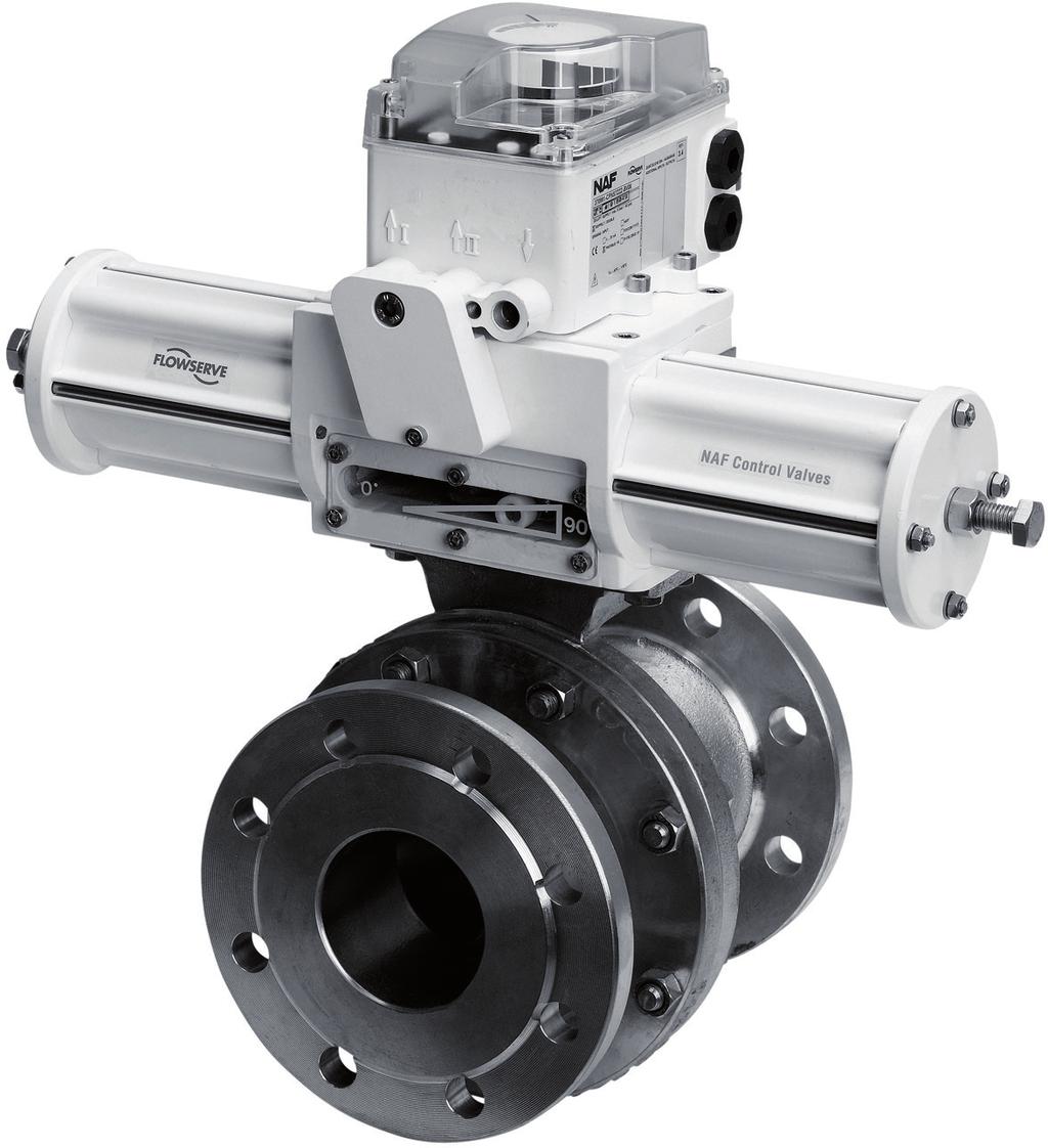
1 USER INSTRUCTIONS NAF Duball DL Ball Valves FCD NFENIM A4 01/17 Installation Operation Maintenance 1 Experience In Motion
2 Contents SAFETY 3 1 General 3 2 Lifting 4 3 Receiving Inspection 4 4 Installation 4 5 Commissioning 4 6 Bill of Materials and Recommended Spare Parts Kits 5 7 Ordering of Spare Parts 6 8 Maintenance Removing the valve from the pipework Disassembling the valve for inspection and replacement of ball, seats and stem packing Valves with PTFE seat rings Valves with hard chrome plated ball and seat rings in Alloy Valves (incl. NAF Pocket ball) with ball and seats in Alloy Sealed seat version (T-version) Changing the stem packing 8 9 Fitting an Actuator to the Valve 9 2
3 SAFETY Assess all risks to eliminate the possibility of personal injury and material damage. Read these instructions thoroughly. Always use the necessary protective equipment and comply with applicable safety directives when working with hazardous or hot/cold media. Never operate a valve without first ensuring there is no risk of crush injuries. The risk is highest with automated valves. Take necessary safety precautions to avoid unintentional stroking of the actuator / valve. Never dismantle a valve or part of a valve without ensuring the line is free of pressure and media. Ball valves must always be dismantled in the semi-open position to avoid trapping pressure and media. Always check that the valve type and material is suitable for its intended use. This applies especially to highly oxidizing and corrosive media. Observe also the risk of erosion or explosion, as well as decaying medium. If in doubt, always request a written recommendation from Flowserve. 1 General This instruction provides necessary information for the correct handling of the NAF Duball DL ball valve. For additional equipment used together with the valve, please refer to their corresponding instructions. Although this instruction is made to cover a broad range of varieties of the NAF Duball DL, there will inevitably be versions not covered in detail. If you have any doubt about the correct use and handling of a specific version of NAF Duball DL, please contact your Flowserve representative. Valves intended for use on highly oxidizing media are often delivered in a degreased version. Any valve marked with Degreased for oxygen service must be handled with the greatest care and be protected from being contaminated with grease, dust or anything else that can jeopardize its safe use. The instructions and list of spare parts in this document are applicable to NAF Duball DL ball valves in accordance with our technical bulletin. 3

4 2 Lifting All lifting must be carried out on the valve itself and not on the actuator. The mounting connection between the valve and the actuator is designed principally for carrying the operating torque and the deadweight of the actuator and is not designed to support the weight of the valve. See Figure 1. Figure 1. Lifting of the valve 4 Installation Before installing the valve, ensure the pipework is free from impurities, that the pipe end connectors between which the valve is to be installed are parallel and are correctly aligned, and that the distance between the pipe ends correspond to the valve length, including gaskets. The valve must not be used for drawing together or aligning incorrectly run pipes as this will cause improper loads on the valve and pipe which could lead to difficult problems during operation. See Figure 2. Figure 2. Ensure that the pipe ends align and have the correct gap Incorrect installation Correct installation NAF Duball DL valves can be installed in any orientation and for either direction of flow. 3 Receiving Inspection All valves leaving our facility are inspected and tested in accordance with the relevant requirements or in accordance with the special provisions specified by the purchaser. Valves equipped with actuators are subjected to functional testing and are adjusted in such a manner that every unit is ready for direct installation in the pipework. However, because damage may have occurred during transport, it is advisable that receiving inspection be carried out. We suggest the following inspection procedure: Check that the valve delivered is correct in terms of type, size, equipment, etc. Examine the valve, actuator and valve positioner for possible damage. However, we recommend that if installed in a horizontal run of pipe, the valve should be mounted with the stem pointing vertically upwards. The pipes should be supported on each side of the valve in order to relieve the valve of unnecessary loads and avoid vibrations. Locate the valve so it will be easily accessible for inspection and service, particularly if the valve is equipped with an actuator and a valve positioner. 5 Commissioning Before starting up, flush the pipework with all valves in the open position so that any impurities that may damage the sealing surfaces of the valve or impede its operation will be flushed away. 4
5 Figure Bill of Materials and Recommended Spare Parts Kits Item Qty Part Kit A Stem sealing kit Kit B Seat ring kit (soft seated) Kit C Ball kit (soft seated) Kit D Seat and ball kit (metal seated) Kit E Seat seal kit 1 1 Body, main 2 1 Body, cover 3 1 Ball X X 4 2 Seat ring X X 5 1 Stem 6 1 Circlip X 7 1 Cover 8 1 Spring X 9 1 Washer X 10 1 Stem packing X 11 1 Washer X 12 1 Bushing X 13 1 Anti-friction washer X 14 1 Body seal X 15 1) Seat seal X 16 2) Screw 17 2 Stud 18 2) Bolt 19 2) Nut 20 2 Key 5 1) Quantity: 0 for soft seated valves, 2 pcs for metal seated valves. 2) Quantity depending on size of the valve. Material and design of the parts vary depending on the version of the valve. Version is determined by NAF No. on the identification plate of the valve.
6 7 Ordering of Spare Parts When placing an order for spare parts, specify: NAF-No: specified on the identification plate of the valve. Recommended spare part kit according to section 6. Quantity required. Ordering example: NAF-No: Spare part kit: Quantity: 8 Maintenance 8885KF-0200-BABAEA A 1pc Many valves are installed in locations where their performance is of critical importance to the entire process. Such valves should be inspected regularly and any issues should immediately be corrected. Valves intended for use on highly oxidizing media require special handling, such as cleanliness and use of special grease, to avoid safety hazards. Applicable regulations must be followed and the following maintenance instructions can therefore only serve as general guidance. 8.1 Removing the valve from the pipework The procedure for inspection and maintenance requires no special tools. Ensure the process line is shut off, free of pressure and drained of media. 1 Ensure that the recommended spare parts and gaskets for the pipe flanges are available. 3 Shut off all compressed air connections and isolate all electrical connections to the actuator. 4 Disconnect all compressed air lines and electric cables connected to the actuator. Caution. Liquid in the valve may be harmful. 5 Release the flanged joint between the valve and the pipework. Then lift out the valve. Don t use the actuator for lifting. Apply all lifting forces to the valve itself and not to the actuator. See Figure Disassembling the valve for inspection and replacement of ball, seats and stem packing For part numbers, refer to Figure 3. 1 The actuator does not need to be removed for replacing the seat rings and ball. However if the stem seal is leaking, the stem packing must be replaced. Even if the stem seal does not leak, we always recommend replacing the stem packing every time the valve is disassembled. This will prevent unnecessary extra work and downtime caused by a stem leakage in the future. We always recommend the use of a stem sealing kit, spare part kit A. 2 Operate the valve to make certain that it is completely empty of process media. Close the valve. 3 Remove the body cover (2). 4 Remove the ball (3), which is simple to do when the valve is in the closed position. See Figure 4. Figure 4. Lifting the ball with the valve in closed position here with the valve on a work bench, but it can be done with mounted actuator 2 Before removing the valve from the pipeline, operate it several times between the open and closed position to ensure that any trapped media / pressure is released. 6
7 5 Carefully inspect the ball (3) and seat rings (4). 6 Clean all parts thoroughly. First use hot water and then degreasing agent, if necessary. Don t scrape any of the machined surfaces with hard tools. 8.3 Valves with PTFE seat rings 1 To ensure tightness of the valve, fit new seat rings (4) if the original ones are worn or damaged. 2 Inspect the ball (3). Minor damage to the sealing surface can be removed by rubbing down with fine emery cloth. If the ball has sustained major damage, it must be replaced to ensure satisfactory sealing. 3 Fit a new body seal (14) between the two halves (1, 2) of the body. 4 Coat the ball (3) with Molycote U. If the valve is intended for service in an oxygen system, a grease suitable for oxygen service must be used. 5 Lubricate all studs/bolts (17, 18) with suitable anti-galling grease. 6 Fit the ball (3) in the main body (1). See Figure 4. Then fit the body cover (2). Note: The main body (1) and body cover (2) will only fit in one position. 7 Lubricate the contact surface of the nuts (19) with a suitable anti-galling grease and put the nuts onto the studs/bolts (17, 18). Tighten the bolted joint of the two body halves (1, 2) of the body alternately in several stages, and finally tighten according to the torque as below Bolt Torque Nm Bolt Torque Nm M12 76 UNC 1/2 89 M UNC 5/8 175 M UNC 3/4 308 M UNC 7/8 493 UNC Operate the valve between the closed and open positions. 9 If possible, pressure test the valve with water to check its tightness. See Figure 5 and 6. Testing with the use of gaseous media is not recommended due to safety issues. Make sure that the cavities of the valve are properly filled with liquid before pressure testing. This is most easily done by placing the valve in the vertical position and filling the valve in the semi open position with liquid. Testing the valve body tightness (5) should not be performed at a pressure higher than 1.5 x maximum allowed working pressure. Refer to Technical Bulletin NFENTB4167 Testing of the ball and seat tightness (6) should not be performed at a pressure higher than 1.1 x maximum allowed differential pressure (see Technical Bulletin). Due to the floating action of the ball, the ball needs a certain volume flow to effectively seal the ball against the seat. We recommend for valve sizes DN150/6 and larger, that the inlet pipe connection is a minimum of 25 mm/1. 10 If the valve has been pressure tested, please check and, if needed, re-tighten the bolts according to Valves with hard chrome plated ball and seat rings in Alloy 6 1 Check the sealing surfaces of the seat rings (4). A groove on the inside diameter of the seat facilitates withdrawal. Minor damage to the seats can be rubbed down with fine emery cloth. Check the seats on a face plate to ensure that they are perfectly flat. Don t lap the seats and the chromium-plated ball together. Change the seats if they are severely damaged. 2 Inspect the sealing surface of the ball (3). Minor damage may be rubbed down with fine emery cloth. If the existing ball must be used for a further period of time, remove all sharp edges, dents and irregularities with a fine file or emery cloth. If the ball is severely damaged, the complete ball set must be replaced. 3 Fit the seat seal (15) behind the seat rings. The seat seals must be fitted with the sharp edge towards the body half. 4 Grease the ball (3) with a suitable grease, such as Klüber Unisilicone L641 or similar. If the valve is intended for service in an oxygen system, a grease suitable for oxygen service must be used. 5 Continue assembling the valve as described in items 5 10 in section
8 Figure 5. Testing of body tightness Valve open Sealing flange 4 Balls in Alloy 6 must be carefully cleaned and greased before they are fitted. Use a suitable solvent for cleaning. Then grease the ball with Klüber Barrierta L55/3 H8 or similar. This coat of grease must be very thin. If the valve is intended for service in an oxygen system, a grease suitable for oxygen service must be used. 8.6 Sealed seat version (T-version) 1 The instructions for these valves are the same as those in section 8.4, with the exception of how the seat seals are mounted. 2 Seat rings with double o-rings must be vented during assembly. The easiest way to do this is to use a feeler gauge. See Figure 7. Figure 7. Venting using feeler gauge Water Figure 6. Testing of ball and seat tightness Valve closed Feeler gauge 8 Water 8.5 Valves (including NAF Pocket ball) with ball and seats in Alloy 6 1 The instructions for these valves are the same as those in section 8.4. If the sealing surfaces are damaged, we recommend that the valve is returned to Flowserve for overhaul. This applies in particular if the ball must be ground before lapping. Assemble the valve before dispatching it to Flowserve. 2 The ball (3) and seat rings (4) can be temporarily overhauled by lapping them together. This can be done manually with a compound with grit size 200. Take great care to ensure that the ball and seat rings do not become oval. 3 New seat rings (4) can be supplied grounded and lapped together with a Master-ball. Some additional machining of the rear side of the rings may be necessary in order to optimize fit. It is always recommended to order a complete Ball set. 8.7 Replacing the stem packing If the stem seal is leaking, the stem packing must be replaced. Even if the stem seal does not leak, we always recommend replacing the stem packing every time the valve is disassembled. This will prevent unnecessary extra work and downtime caused by a stem leakage in the future. We always recommend the use of a stem sealing kit, spare part kit A. Make sure that the valve is not under pressure. 1 Remove any actuator. 2 Remove the keys (20). 3 Remove the circlip (6), back off the screws (16), and remove the cover (7) and the spring (8). 4 Disassemble the valve as described in section Press the stem (5) down into the body and remove it. 6 Press the bushing (12) down into the body and remove it. 7 Remove the stem packing (10) and washers (9) and (11). See Figure 8.
9 Figure 8. Stem packing for standard (left) and fire-safe version (right) Standard stem packing Stem packing for fire-safe version Note: correct location for graphite ring 8 Fit a new anti-friction washer (13) to the stem (5) followed by a new bushing (12). Then fit the stem assembly (5, 12, 13) into the valve body. 9 Fit washer (11) and a new stem packing (10) using a suitable silicon grease. Please note that for valves in a fire-safe version, the graphite ring of the stem packing (10) must be placed on top of the stem packing. See right part of Figure Fit washer (9) and spring (8). 11 Fit cover (7) and tighten the screws (16) alternately in several stages. 12 Fit the circlip (6). 9 Fitting an Actuator to the Valve 1 Fit the actuator to the valve. Ensure that both the valve and the actuator are in the closed position before fitting the actuator. The valve is in the closed position when the keys (20) in the stem (5) face in the direction of flow. (An actuator which uses compressed air to close the valve and a return spring to open the valve should be fitted with the actuator and valve in the open position.) 2 Check the operation and check that the end stops have been correctly preset or adjust them so the ball is in the correct position. Note The direction of closure must always be clockwise, as viewed from the actuator. 13 Assemble and, if possible, pressure test, the valve as described in items 5 10 in section 8.3. However, first assess whether the seat rings should be replaced or whether the seat rings and ball should be lapped together. 9
10 Page intentionally left blank 10
11 Page intentionally left blank 11
12 NAF AB SE Linköping Sweden Telephone: Facsimile: Website: www. NFENIM A4 To find your local Flowserve representative or for more information about Flowserve Corporation, visit Flowserve Corporation has established industry leadership in the design and manufacture of its products. When properly selected, this Flowserve product is designed to perform its intended function safely during its useful life. However, the purchaser or user of Flowserve products should be aware that Flowserve products might be used in numerous applications under a wide variety of industrial service conditions. Although Flowserve can (and often does) provide general guidelines, it cannot provide specific data and warnings for all possible applications. The purchaser/user must therefore assume the ultimate responsibility for the proper sizing and selection, installation, operation, and maintenance of Flowserve products. The purchaser/user should read and understand the Installation Operation Maintenance (IOM) instructions included with the product, and train its employees and contractors in the safe use of Flowserve products in connection with the specific application. While the information and specifications contained in this literature are believed to be accurate, they are supplied for informative purposes only and should not be considered certified or as a guarantee of satisfactory results by reliance thereon. Nothing contained herein is to be construed as a warranty or guarantee, express or implied, regarding any matter with respect to this product. Because Flowserve is continually improving and upgrading its product design, the specifications, dimensions and information contained herein are subject to change without notice. Should any question arise concerning these provisions, the purchaser/user should contact Flowserve Corporation at any one of its worldwide operations or offices Flowserve Corporation, Irving, Texas, USA. Flowserve is a registered trademark of Flowserve Corporation. 12
KTM OM-2 SPLIT BODY FLOATING BALL VALVES INSTALLATION AND MAINTENANCE INSTRUCTIONS
 Before installation these instructions must be fully read and understood SECTION 1 - STORAGE 1.1 Preparation and preservation for storage All valves should be properly packed in order to protect the parts
FLANGED TWO-PIECE BALL VALVES
 INTRODUCTION This instruction manual includes installation, operation, and maintenance information for FNW flanged split-body ball valves. This manual addresses lever operated ball valves only. Please
Installation Instructions
 Installation Instructions Durametallic MD-200 Series Gas Dual Cartridge Canister Seal for Mixers and Agitators Experience In Motion 1 Equipment Check 1.1 Follow plant safety regulations prior to equipment
Installation Operation Maintenance
 682 Seal Cooler New generation seal cooler to meet and exceed the seal cooler requirements stated in the 4th Edition of API Standard 682 Installation Operation Maintenance Experience In Motion Description
FLANGED TWO-PIECE BALL VALVES
 INTRODUCTION This instruction manual includes installation, operation, and maintenance information for FNW flanged split-body ball valves. This manual addresses lever operated ball valves only. Please
BSA6T and BSA64T Stainless Steel Bellows Sealed Stop Valves Installation and Maintenance Instructions
 1843950/3 IM-P184-03 ST Issue 3 BSA6T and BSA64T Stainless Steel Bellows Sealed Stop Valves Installation and Maintenance Instructions 1. General safety information 2. General product information 3. Installation
INSTRUCTION MANUAL. Anchor Darling 800 Globe Valves. Installation Operation Maintenance. Sizes 1/2 through 2 FCD ADENIM
 INSTRUCTION MANUAL Anchor Darling 800 Globe Valves Sizes 1/2 through 2 Installation Operation Maintenance FCD ADENIM0008-00 Revision Record Revision Section Description Date - All Original Issue 04/02/2004
Installation Instructions
 Durametallic SL-5000 and SL-5200 Seals Cartridge Slurry Seals Installation Instructions Experience In Motion SL-5000 and SL-5200 Cartridge Seals are complete preset seal assemblies which include the sleeve
Installation Instructions
 Installation Instructions BW Seals Uniseal Series Cartridge metal bellows single and dual seals Experience In Motion Description The Uniseal metal bellows seal series consists of: Uniseal I - Single seals
Installation, Operation and Maintenance Manual for Back Pressure Regulator
 Installation, Operation and Maintenance Manual for Back Pressure Regulator Model 8860 2009 Groth Corporation IOM-8860 Rev. B 12541 Ref. ID: 95565 Page 2 of 13 Table of Contents I. INTRODUCTION 3 II. DESIGN
WHEATLEY Series 500 Swing Check Valve
 Document Number: TC003001-13 Revision: 02 WHEATLEY Series 500 Swing Check Valve Installation, Operation, and Maintenance Manual TABLE OF CONTENTS BILL OF MATERIALS...3 SCOPE...5 INSTALLATION AND OPERATION
RS(H)10,15 USER MANUAL. Read the complete manual before installing and using the regulator.
10,15 USER MANUAL. Read the complete manual before installing and using the regulator.") RS(H)10,15 USER MANUAL Read the complete manual before installing and using the regulator. WARNING INCORRECT OR IMPROPER USE OF THIS PRODUCT CAN CAUSE SERIOUS PERSONAL INJURY AND PROPERTY DAMAGE. Due to
RS(H)10,15 USER MANUAL Read the complete manual before installing and using the regulator. WARNING INCORRECT OR IMPROPER USE OF THIS PRODUCT CAN CAUSE SERIOUS PERSONAL INJURY AND PROPERTY DAMAGE. Due to
Installation Instructions
 Installation Instructions TM Five Star Seal 80 Series Dual, Cartridge Mounted, Flexible Stator Pusher Seal Designed for General Service Applications 86 and 87 Experience In Motion Description The 86/87
Installation Operation Maintenance
 Worcester 13 / 14 Series Small three-piece multiway ball valves Installation Operation Maintenance WCENIM0002-01 Original Instructions Copyright All rights reserved. No part of these instructions may be
Apollo Standard Port, Full Port & One Piece Flanged Ball Valves Installation, Operation, & Maintenance Manual
 I854000.D Apollo Standard Port, Full Port & One Piece Flanged Ball Valves Installation, Operation, & Maintenance Manual Introduction This manual presents guidelines for the Installation, Operation and
Installation Instructions For Flat Seated Bolted Type RAH Series Disk Holders
 Installation Instructions For Flat Seated Bolted Type RAH Series Disk Holders RA Series Rupture Disks 1. WARNING a) Read the complete instructions before attempting to install the rupture disk and holder
WHEATLEY WHEATLEY SERIES 500 SWING CHECK VALVE. Installation, Operation and Maintenance Manual
 WHEATLEY SERIES 500 SWING CHECK VALVE STANDARD INTEGRAL SEAT & OPTIONAL REMOVABLE SEAT 2" FP - 6" FP 150# - 1500# 8" FP - 12" FP 150# - 900# API 6D and B16.34 2" FP - 4" FP 5000# DRILLING PRODUCTION VALVE
1.0 - OPENING AND CLOSING THE DOOR
 The purpose of this manual is to provide the user with instructions on how to safely open and close, how to conduct routine maintenance, and how to install the PEI TWINLOCK Closure on a pressure vessel.
Manual Actuated Boiler Blowdown Valves
 Manual Actuated Boiler Blowdown Valves Installation and Maintenance Instructions 1. Safety information 2. General product information 3. Installation 4. Operation 5. Maintenance 6. Spare parts p.1 1. Safety
Edward Valves Equiwedge Forged Gate Valve
 flowserve.com Edward Valves Equiwedge Forged Gate Valve Experience In Motion 1 New Hybrid Design resets Standards The new forged Equiwedge gate valve from Flowserve Edward valves is the ideal engineering
INSTALLATION, MAINTENANCE & OPERATING INSTRUCTIONS 2-4 REDUCED PORT/ FULL PORT (5700/6700) ANSI CLASS 150/300/600/900/1500/2500 TRUNNION BALL VALVES
 ANSI CLASS 150/300/600/900/1500/2500 TRUNNION BALL VALVES") PBV-USA,Inc. 12735 Dairy Ashford. Stafford, Texas USA 77477 281-340-5400; 800-256-6193 FAX: 281-340-5499 INDUSTRIAL BALL VALVES IM0 69 April 2001 Rev 9 INSTALLATION, MAINTENANCE & OPERATING INSTRUCTIONS
PBV-USA,Inc. 12735 Dairy Ashford. Stafford, Texas USA 77477 281-340-5400; 800-256-6193 FAX: 281-340-5499 INDUSTRIAL BALL VALVES IM0 69 April 2001 Rev 9 INSTALLATION, MAINTENANCE & OPERATING INSTRUCTIONS
FLANGED MULTI-PORT BALL VALVES
 INTRODUCTION This instruction manual includes installation, operation and maintenance information for flanged multi-port ball valves. This manual addresses lever operated ball valves only. Please refer
Installation, Operation, & Maintenance Manual NX Seal Cooler
 Installation, Operation, & Maintenance Manual NX Seal Cooler 1 1. INTRODUCTION 1.1 About this Manual This manual is intended to ensure a safe installation and operation of the NX sealcooler. All involved
M45 ISO Ball Valve DN25 to 150 Installation and Maintenance Instructions
 BAC 13310 IM-P133-42 ST Issue 2 M45 ISO Ball Valve DN25 to 150 Installation and Maintenance Instructions 1. General safety information 2. General product information 3. Installation 4. Commissioning 5.
MODEL 200 KNIFE GATE VALVES INSTALLATION & MAINTENANCE MANUAL
 MODEL 200 KNIFE GATE VALVES INSTALLATION & MAINTENANCE MANUAL Index 1. List of components / General arrangement 2. Description 3. Handling 4. Installation 5. Actuators / Operation 6. Maintenance a. Changing
Spilt body Flange ball valve. TC-205MFF-PN1640 User Manual English Version. Document No: TC-205MFF-PN1640.Ur-manual. Date: 2007/04/2617. Version: 1.
 Spilt body Flange ball valve TC-205MFF-PN1640 Series PED Category I,II TC-205MFF-PN1640 User Manual English Version Use for company in Europe who will place the product on the market, please amend which
TBV OPERATION AND MAINTENANCE MANUAL SERIES 2800: FLANGED BALL VALVE. For technical questions, please contact the following:
 TBV OPERATION AND MAINTENANCE MANUAL SERIES 2800: FLANGED BALL VALVE For technical questions, please contact the following: Engineering Department 1537 Grafton Road Millbury, MA 01527 Phone: (508) 887-9400
Telefon (+45) Telefax (+45)
 Telefax (+45)") Uni-Valve A /S VENTILER & INSTRUMENTER Telefon (+45) 43 43 82 00 Telefax (+45) 43 43 74 75 mail@uni-valve.com www.uni-valve.com UNI-S83 / S84 3/4-way ball valve Installation and Operating manual 3/4-WAY
Uni-Valve A /S VENTILER & INSTRUMENTER Telefon (+45) 43 43 82 00 Telefax (+45) 43 43 74 75 mail@uni-valve.com www.uni-valve.com UNI-S83 / S84 3/4-way ball valve Installation and Operating manual 3/4-WAY
Engineering Data Sheet
 Page 1 of 6 CE MARKING AND THE PRESSURE EQUIPMENT DIRECTIVE 97/23/EC Valves must be installed into a well designed system and it is recommended that the system be inspected in accordance with the appropriate
Bray/ VAAS O-Ported Series Knife Gate Valve 770/780 Series Operation and Maintenance Manual
 Bray/ VAAS Knife Gate Valve 770/780 Series Operations and Maintenance Manual Table of Contents Definition of Terms 1 Safety Instructions 1 Introduction 2 Unpacking 2 Storage 2 Installation 2 Commissioning
VALVCHEQ BACKFLOW PREVENTERS FIGURE RP03
 Reduce pressure zone device suitable for high and medium hazard rated applications Flanged end connections FEATURES GENERAL APPLICATION The RP03 provides protection from both backsiphonage and backpressure
DelVal Flow Controls Private limited
 DelVal Flow Controls Private limited (A DIVISION OF DelTech CONTROLS LLC, USA) DelVal Series 50/5, 5A/5B Butterfly Valves INSTALLATION, OPERATION AND MAINTENANCE MANUAL ENGINEERING DATA SHEET E.D.S. NO
ROTATING DISK VALVES INSTALLATION AND MAINTENANCE 1. SCOPE 3 2. INFORMATION ON USAGE 3 3. VALVE TYPES 3 4. OPERATORS 5 5. VALVE CONSTRUCTION 6
 Sub Section INDEX Page Number 1. SCOPE 3 2. INFORMATION ON USAGE 3 3. VALVE TYPES 3 4. OPERATORS 5 5. VALVE CONSTRUCTION 6 6. INSTALLATION AND OPERATION 6 7. MAINTENANCE 8 8. REPAIR 9 9. ASSEMBLY 10 10.
APCO ARV CLEAN WATER AIR RELEASE VALVES. Model 50A
 APCO ARV CLEAN WATER AIR RELEASE VALVES Model 50A Instruction D12013 February 2017 Instructions These instructions provide installation, operation and maintenance information for APCO ARV Clean Water Air
PC3_ and PC4_ Pipeline Connectors
 1283050/4 IM-P128-06 ST Issue 4 PC3_ and PC4_ Pipeline Connectors Installation and Maintenance Instructions 1. Safety information 2. Description PC30 shown 3. Installation 4. Welding of pipeline connector
WKM Model 320F Floating Ball Valve
 Date: 4 WKM Model 320F Floating Ball Valve Installation, Operation, and Maintenance Manual 1 Date: 4 All the information contained in this manual is the exclusive property of Cameron. Any reproduction
SEries 29 Hydrant valves installation, operation & maintenance manual
 Instruction for use Thank you for selecting an AVK product. With correct use, it will give long and reliable service. This manual has been prepared to assist you install, operate and maintain the valve
Operating instruction
 Operating instruction MV, XV, HG, HP, RKO, D2G, TV, BV, WB & SLV 1 Introduction 2 2 Stafsjö s knife gate valves 2 3 Technical information 2 3.1 Pressure test 2 3.2 Labelling 2 4 Storage 3 5 Transportation
Assembly Drawing: W-311B-A01, or as applicable Parts List: W-311B-A01-1, or as applicable Special Tools: , , &
 REDQ Regulators Model 411B Barstock Design Powreactor Dome Regulator OPERATION AND MAINTENANCE Contents Scope..............................1 Installation..........................1 General Description....................1
Installation & Operation Manual Proven Quality since 1892
 Content 1. ERIKS operating companies 2. Product description 3. Requirements for maintenance staff 4. Transport and storage 5. Function 6. Application 7. Installation 8. Maintenance 9. Service and repair
3-PIECE BALL VALVE, 3600 PSI/ PN 248, WITH ISO DIRECT MOUNTING PAD 306M SERIES/ PED Category II
 3-PIECE BALL VALVE, 3600 PSI/ PN 248, WITH ISO DIRECT MOUNTING PAD 306M SERIES/ PED Category II 306M User Manual English Version Use for company in Europe who will place the product on the market, please
KBV21i and KBV40i Key Operated Boiler Blowdown Valves Installation and Maintenance Instructions
 4059051/3 IM-P405-48 EMM Issue 3 KBV21i and KBV40i Key Operated Boiler Blowdown Valves Installation and Maintenance Instructions 1. Safety information 2. General product information 3. Installation 4.
TD45 Thermodynamic Steam Trap Installation and Maintenance Instructions
 0685255/1 IM-P068-47 ST Issue 1 TD45 Thermodynamic Steam Trap Installation and Maintenance Instructions 1 General safety information 2 General product information 3 Installation 4 Commissioning 5 Operation
SA Control Valve types: BM, BMF, BX, SB, NS, KA, KB, KC (Normally open) BMRA, BMFRA, BXRA, SBRA, NSRA, KX, KY (Normally closed)
 BMRA, BMFRA, BXRA, SBRA, NSRA, KX, KY (Normally closed)") 0366055/7 IM-S21-01 CH Issue 7 SA Control Valve types: BM, BMF, BX, SB, NS, KA, KB, KC (Normally open) BMRA, BMFRA, BXRA, SBRA, NSRA, KX, KY (Normally closed) Installation and Maintenance Instructions
0366055/7 IM-S21-01 CH Issue 7 SA Control Valve types: BM, BMF, BX, SB, NS, KA, KB, KC (Normally open) BMRA, BMFRA, BXRA, SBRA, NSRA, KX, KY (Normally closed) Installation and Maintenance Instructions
INSTALLATION, OPERATION and MAINTENANCE MANUAL
 INSTALLATION, OPERATION and MAINTENANCE MANUAL TRUNNION MOUNTED BALL VALVE NEXTECH I ValvTechnologies, Inc. 5904 Bingle Road Houston, Texas 77092 U.S.A. Email: sales@valv.com www.valv.com 705_Nextech IOM
KBV21i and KBV40i Air Actuated Boiler Blowdown Valves
 4059051/1 IM-P405-48 AB Issue 1 KBV21i and KBV40i Air Actuated Boiler Blowdown Valves Installation and Maintenance Instructions 1. Safety information 2. General product information 3. Installation 4. Commissioning
PRS(TC)4,8 USER MANUAL. Read the complete manual before installing and using the regulator.
4,8 USER MANUAL. Read the complete manual before installing and using the regulator.") PRS(TC)4,8 USER MANUAL Read the complete manual before installing and using the regulator. WARNING INCORRECT OR IMPROPER USE OF THIS PRODUCT CAN CAUSE SERIOUS PERSONAL INJURY AND PROPERTY DAMAGE. Due to
PRS(TC)4,8 USER MANUAL Read the complete manual before installing and using the regulator. WARNING INCORRECT OR IMPROPER USE OF THIS PRODUCT CAN CAUSE SERIOUS PERSONAL INJURY AND PROPERTY DAMAGE. Due to
Contents. 1. General information BROEN BALLOMAX Steel Ball Valves Approvals Quality Management...2
 Contents 1. General information...2 1.1 BROEN BALLOMAX Steel Ball Valves...2 1.2 Approvals...2 1.3 Quality Management...2 2. Preoperational Instructions and Precautions...2 3. Plates...3 4. Transport and
OPERATING MANUAL. Contents. Bottom outlet ball valve Type ecoline
 OPERATING MANUAL Bottom outlet ball valve Type ecoline Contents 1 General Information 2 Safety 3 Packing, Handling, Storing 4 Product description 5 Preparation, Assembly 6 Commissioning 7 Handling 8 Attendance
INSTALLATION, OPERATION AND MAINTENANCE GUIDE
 INSTALLATION, OPERATION AND Placement in Pipeline System When installing Process Development & Control s ElastoTITE Elastomer-Hinged Check Valves in a pipeline, a minimum of five pipe diameters should
Type BBS-03, BBS-05, BBS-06, BBS-25
 Type BBS-03, BBS-05, BBS-06, BBS-25 Sterile connection elements Sterile Verbindungselemente Raccords union stériles Operating Instructions Bedienungsanleitung Manuel d utilisation 1. THE OPERATING INSTRUCTIONS
Sempell High Pressure Forged Check Valves Forged steel, swing check and tilting disc configuration
 Installation and Maintenance Instructions Handling requirements A - Packed valves Pallets: Lifting and handling of the packed valves in pallets will be carried out by a fork lift truck, by means of the
SALCO PRODUCTS, INC. PRESSURE RELIEF VALVE STORAGE, INSTALLATION, OPERATING, MAINTENANCE/TESTING, AND INSPECTION INSTRUCTIONS
 STORAGE INSTRUCTIONS Until it is time to install a new or reconditioned valve on the car, the valve must be kept in its original packaging in order to protect it from dirt and damage. INSTALLATION INSTRUCTIONS
Installation, Operation, and Maintenance Manual
 Installation, Operation, and Maintenance Manual Welker Probe Instrument Regulator Model The information in this manual has been carefully checked for accuracy and is intended to be used as a guide for
Crosby style JCE Safety Valve Installation, Maintenance and Adjustment Instructions CROSBY
 CROSBY Table of contents 1. Installation 1 1.1. Drainage 1 1.2. Discharge pipework 1 1.3. Preparation for installation 1 2. Pressure adjustment 1 3. Maintenance 1 4. Dismantling 1 4.1. All valve types
LRS(H)4 USER MANUAL. Read the complete manual before installing and using the regulator.
4 USER MANUAL. Read the complete manual before installing and using the regulator.") LRS(H)4 USER MANUAL Read the complete manual before installing and using the regulator. WARNING INCORRECT OR IMPROPER USE OF THIS PRODUCT CAN CAUSE SERIOUS PERSONAL INJURY AND PROPERTY DAMAGE. Due to the
LRS(H)4 USER MANUAL Read the complete manual before installing and using the regulator. WARNING INCORRECT OR IMPROPER USE OF THIS PRODUCT CAN CAUSE SERIOUS PERSONAL INJURY AND PROPERTY DAMAGE. Due to the
A3S Bellows Sealed Stop Valve Installation and Maintenance Instructions
 1326050/3 IM-P132-11 ST Issue 3 A3S Bellows Sealed Stop Valve Installation and Maintenance Instructions 1 General safety information 2 General product information 3 Installation 4 Commissioning 5 Operation
Instructions for Installation, Operating and Maintenance
 Instructions for Installation, Operating and Maintenance for ABO butterfly valves series 500 1) Introduction 2) Safety Instructions 3) Valve Identification 4) Transportation and Storage 5) Installation
MSC-P and MSC-N Manifolds for Steam Distribution and Condensate Collection
 1170850/1 IM-P117-36 ST Issue 1 MSC-P and MSC-N Manifolds for Steam Distribution and Condensate Collection Installation and Maintenance Instructions 1. Safety information 2. General product information
LRS(H)4 Pressure-Reducing Regulator User Manual
4 Pressure-Reducing Regulator User Manual") LRS(H)4 Pressure-Reducing Regulator User Manual Read the complete manual before installing and using the regulator. 2 Safe Product Selection When selecting a product, the total system design must be considered
LRS(H)4 Pressure-Reducing Regulator User Manual Read the complete manual before installing and using the regulator. 2 Safe Product Selection When selecting a product, the total system design must be considered
VALVCHEQ BACKFLOW PREVENTERS FIGURE RP03
 Reduce pressure zone device suitable for high and medium hazard rated applications BSP screwed connections FEATURES GENERAL APPLICATION The RP03 provides protection from both backsiphonage and backpressure
EASTERN ENERGY SERVICES PTE LTD. 60 Kaki Bukit Place #02-19 Eunos Tech Park Singapore, SG Singapore Telephone: Fax:
 2 Table Of Contents 1. Introduction 3 2. About this Manual 3 3. Contacting YZ Systems 3 4. Vessel Components 4 5. Specifications 5 6. Application 6 7. Theory of Operation 7 8. DuraSite Installation & Use
INSTRUCTIONS AND MAINTENANCE MANUAL SERIES: RT
 INSTRUCTIONS AND MAINTENANCE MANUAL 05/11/2015 SERIES: RT cmo @cmo.es http://www.cmo.es page 1 ASSEMBLY THE RT VALVE COMPLIES WITH THE FOLLOWING: Machinery Directive: DIR 2006/42/EC (MACHINERY) Pressure
INSTALLATION, OPERATION AND MAINTENANCE MANUAL. Model Sanitary Vent SECTION I
 INSTALLATION, OPERATION AND MAINTENANCE MANUAL Model 1100 Sanitary Vent IOM-1100 03-17 ISO Registered Company SECTION I I. DESCRIPTION AND SCOPE The Model 1100 is a stainless steel sanitary vent designed
INSTRUCTIONS AND MAINTENANCE MANUAL SERIES: FK
 INSTRUCTIONS AND MAINTENANCE MANUAL 04/09/2014 SERIES: FK cmo@cmo.es http://www.cmo.es Page 1 ASSEMBLY THE FK VALVE COMPLIES WITH THE FOLLOWING: Machinery Directive: DIR 2006/42/EC (MACHINERY) Pressure
INSTALLATION COMMISSIONING, OPERATION & MAINTENANCE MANUAL
 WedgeRock RW Series Worm Gear Actuators INSTALLATION COMMISSIONING, OPERATION & MAINTENANCE MANUAL Revision 01 Date 4/3/17 Page 1 Table of Contents 1.0 INTRODUCTION... 4 1.1 PURPOSE... 4 1.2 AUDIENCE...
FTGS14 Ball Float Steam Trap DN15 (½") to DN25 (1")
 to DN25 (1)") 1458050/5 IM-P145-12 ST Issue 5 FTGS14 Ball Float Steam Trap DN15 (½") to DN25 (1") Installation and Maintenance Instructions 1. Safety information 2. General product information 3. Installation 4. Commissioning
1458050/5 IM-P145-12 ST Issue 5 FTGS14 Ball Float Steam Trap DN15 (½") to DN25 (1") Installation and Maintenance Instructions 1. Safety information 2. General product information 3. Installation 4. Commissioning
Wafer Check Valve. Contents. User s Manual. (1) Be sure to read the following description of our product warranty 1
 Be sure to read the following description of our product warranty 1") Serial No. H-V066-E-3 Wafer Check Valve User s Manual Contents (1) Be sure to read the following description of our product warranty 1 (2) General operating instructions 2 (3) General instructions for
Serial No. H-V066-E-3 Wafer Check Valve User s Manual Contents (1) Be sure to read the following description of our product warranty 1 (2) General operating instructions 2 (3) General instructions for
Differential Pressure Regulator Type Type 45-6 (0.1 to 1 bar, DN 15) Mounting and Operating Instructions EB 3226 EN
 Mounting and Operating Instructions EB 3226 EN") Differential Pressure Regulator Type 45-6 Type 45-6 (0.1 to 1 bar, DN 15) Mounting and Operating Instructions EB 3226 EN Edition March 2008 Contents Contents Page 1 Design and principle of operation...................
Differential Pressure Regulator Type 45-6 Type 45-6 (0.1 to 1 bar, DN 15) Mounting and Operating Instructions EB 3226 EN Edition March 2008 Contents Contents Page 1 Design and principle of operation...................
BCV31 DN20 - Blowdown Control Valve
 4034650/8 IM-P403-37 AB Issue 8 BCV31 DN20 - Blowdown Control Valve Installation and Maintenance Instructions 1. Safety information 2. Application 3. Technical data 4. Operation 5. Installation 6. Flow
Installation and operating manual. Pneumatic control station LK product no: PCS 1-10
 LK product no: PCS 1-10 Article no: 74503 Revision:8 Article no: 74503 Revision: 8 2 (23) Contents 1. General information... 5 2. Safety precautions... 5 2.1 Significance of symbols... 5 2.2 Explanatory
VALVES & MEASUREMENT
 VALVES & MEASUREMENT TBV OPERATION AND MAINTENANCE MANUAL SERIES 1100: THREE PIECE BALL VALVE For technical questions, please contact the following: Engineering Department 1537 Grafton Road Millbury, MA
M33F ISO, M33S ISO and M33V ISO Ball Valves Installation and Maintenance Instructions
 BAC13365 IM-P133-65 CMGT Issue 2 M33F ISO, M33S ISO and M33V ISO Ball Valves Installation and Maintenance Instructions 1. Safety information 2. General product information 3. Installation 4. Commissioning
CRP INSTALLATION, OPERATING AND MAINTENANCE INFORMATION FOR INLINE SAMPLING VALVES
 CRP INSTALLATION, OPERATING AND MAINTENANCE INFORMATION FOR INLINE SAMPLING VALVES Sampling Valves Installation Commissioning and Operating Instructions SD IL 300 & SD IL 400 Inline Sampling Valve This
Johnston Invar Coupling Johnston Invar Coupling
 Johnston Invar Coupling Rev.10 (2017.07) AvdS Page 1 of 8 Table of contents I. STRUCTURE OF THE MANUAL / CLARIFICATION... 3 II. SAFETY AND HEALTH CONCERNS... 4 1 GENERAL REMARK... 5 2 ASSEMBLY INSTRUCTIONS...
OPERATING AND MAINTENANCE MANUAL
 CONTENTS PAGE INTRODUCTION 1 Installation Compatibility 1 Required Tools and Materials 1 Preparing Valve and Flanges 1 1.0 INSTALLATION 2 1.1 INSTALLATION OF ALL 2- TO 12-IN. SPAN-TYPE VALVES 2 1.2 INSTALLATION
Type /2-Way Globe Valve 3/2-Wege-Geradsitzventil Vanne à siège droit 3/2 voies Operating Instructions Bedienungsanleitung Manuel d utilisation
 3/2-Way Globe Valve 3/2-Wege-Geradsitzventil Vanne à siège droit 3/2 voies Operating Instructions Bedienungsanleitung Manuel d utilisation We reserve the right to make technical changes without notice.
Mounting and Operating Instructions EB 2558 EN. Self-operated Pressure Regulators. Type Pressure Build-up Regulator
 Self-operated Pressure Regulators Type 2357-31 Pressure Build-up Regulator with safety function and integrated excess pressure valve Type 2357-31 with non-return unit at port C Ports A and B with soldering
Installation / Operation / Maintenance Manual KLINGER Reflex Level Gauge Type R 25
 Klinger Italy S.r.l Via De Gasperi, 88 20017 Rho, Mi - Italy Tel. +39 02 93333.1 Fax +39 02 93901312/3 www.klinger.it Telephone: +61 (08) 9350 1100 Facsimile: +61 (08) 9358 6200 ABN 95 008 679 838 Installation
P5513. Users Manual. Pneumatic Comparison Test Pump. Test Equipment Depot Washington Street Melrose, MA TestEquipmentDepot.
 Test Equipment Depot - 800.517.8431-99 Washington Street Melrose, MA 02176 TestEquipmentDepot.com P5513 Pneumatic Comparison Test Pump Users Manual PN 3963372 November 2010 2010 Fluke Corporation. All
M10HTi ISO Tobacco Ball Valve Screwed, SW, BW and Flanged versions
 IM-P133-75 ST Issue 1 M10HTi ISO Tobacco Ball Valve Screwed, SW, BW and Flanged versions Installation and Maintenance Instructions 1. Safety information 2. General product information 3. Installation 4.
WW-730. Pressure Sustaining/Relief Control Valve
 WW-730 Pressure Sustaining/Relief Control Valve Installation Operation & Maintenance Page 1 of 6 1. DESCRIPTION The Model 730 Pressure Relief / Sustaining Valve is an automatic control valve designed to
USM21 Sealed Bimetallic Steam Trap for use with Pipeline Connectors Installation and Maintenance Instructions
 6250250/1 IM-P625-03 ST Issue 1 USM21 Sealed Bimetallic Steam Trap for use with Pipeline Connectors Installation and Maintenance Instructions 1. General safety information 2. General product information
WHEATLEY Series 822/820 Swing Check Valve
 Document Number: TC003001-12 Revision: 02 WHEATLEY Series 822/820 Swing Check Valve Installation, Operation, and Maintenance Manual TABLE OF CONTENTS BILL OF MATERIALS...3 SCOPE...4 INSTALLATION AND OPERATION
WW-720. Pressure Reducing Control Valve
 WW-720 Pressure Reducing Control Valve (Size Ranges: 2-4 and 6-14 ) Installation Operation & Maintenance Page 1 of 6 1. DESCRIPTION The Model 720 Pressure Reducing is an automatic control valve (powered
1. Preface Important Safety Notes Brief Product Information Product Working Principle Installation Guidelines...
 Table of Contents 1. Preface...1 2. Important Safety Notes...1 3. Brief Product Information...3 4. Product Working Principle...5 5. Installation Guidelines...6 6. Startup and Commissioning...8 7. Maintenance
TITAN FLOW CONTROL, INC.
 PREFACE: This manual contains information concerning the installation, operation, and maintenance of Titan Flow Control (Titan FCI) Simplex Basket Strainers. To ensure efficient and safe operation of Titan
Reduce pressure zone device suitable for high and medium hazard rated applications Flanged end connections
 VALVCHEQ Backflow Preventers Reduce pressure zone device suitable for high and medium hazard rated applications Flanged end connections Features General application The RP03 provides protection from both
SAPAG. Safety valves, type 5700 Storage, Use, Operation and Maintenance Instructions. IMPORTANT NOTICE
 SAPAG IMPORTANT NOTICE Contents Important notice 1 0 Valve identification 2 1 Storage 2 2 Installation 2 3 Operation 2 4 Maintenance 3 4.1 Dismantling 3 4.2 Inspection 3 4.3 Repair 3 4.4 Assembly 4 4.5
Installation, operation & maintenance manual - original version
 Installation, operation & maintenance manual - original version AVK gate valves for water and wastewater Series 01, 02, 06, 12, 15, 18, 20, 26, 32, 33, 36, 38, 50, 55 and 636 COPYRIGHT AVK GROUP A/S 2018
Mooney * Noise Controller Installation, Operation, and Maintenance Manual
 GE Oil & Gas Mooney * Noise Controller Installation, Operation, and Maintenance Manual imagination at work Scope This manual provides instructions for installation, operation and maintenance of the Mooney
APP pumps APP and APP Disassembling and assembling
 Service guide APP pumps APP 11-13 and APP 16-22 Disassembling and assembling hpp.danfoss.com Table of Contents Contents 1. Introduction... 2 2. Disassembling the pump... 3 3. Assembling the pump... 6 4.
Installation Instructions
 Installation Instructions Durametallic SLM-6000, SLM-6100 Self contained cartridge medium duty slurry seal Experience In Motion 1 Cartridge Installation Instructions The following instruction manual is
INSTRUCTIONS ON INSTALLATION, OPERATION AND MAINTENANCE FOR KIRLOSKAR MULTI DOOR NON RETURN VALVES
 INSTRUCTIONS ON INSTALLATION, OPERATION AND MAINTENANCE FOR KIRLOSKAR MULTI DOOR NON RETURN VALVES KIRLOSKAR BROTHERS LIMITED MANUFACTURING UNIT, KONDHAPURI (PUNE) INDEX 1 Introduction 2 Inspections on
INSTRUCTIONS AND MAINTENANCE MANUAL SERIES: K
 INSTRUCTIONS AND MAINTENANCE MANUAL 05/09/2014 SERIES: K cmo@cmo.es http://www.cmo.es Page 1 ASSEMBLY DESCRIPTION Machinery Directive: DIR 2006/42/EC (MACHINERY) Pressure Equipment Directive: DIR 97/23/EC
Needle valve. Contents. User s Manual. (1) Be sure to read the following warranty clauses of our product 1. (2) General operating instructions 2
 Be sure to read the following warranty clauses of our product 1. (2) General operating instructions 2") Serial No. H-V024-E-7 Needle valve User s Manual Contents (1) Be sure to read the following warranty clauses of our product 1 (2) General operating instructions 2 (3) General instructions for transportation,
Serial No. H-V024-E-7 Needle valve User s Manual Contents (1) Be sure to read the following warranty clauses of our product 1 (2) General operating instructions 2 (3) General instructions for transportation,
Flowmeter. Original operating manual DFM
 Flowmeter Original operating manual Series DFM 165 350 Version BA-2016.08.09 EN Print-No. 300 458 TR MA DE Rev002 ASV Stübbe GmbH & Co. KG Hollwieser Straße 5 32602 Vlotho Germany Phone: +49 (0) 5733-799-0
Type 2000 INOX. Quickstart. English Deutsch Français. 2/2-way angle seat valve 2/2-Wege Schrägsitzventil Vanne à siège incliné 2/2 voies
 Type 2000 INOX 2/2-way angle seat valve 2/2-Wege Schrägsitzventil Vanne à siège incliné 2/2 voies Quickstart English Deutsch Français Contents 1 QUICKSTART... 2 2 CONTACT ADDRESS... 2 3 INTENDED USE...
PV4 and PV6 Piston Valves
 1181250/1 IM-P118-05 ST Issue 1 PV4 and PV6 Piston Valves Installation and Maintenance Instructions 1. Safety information 2. General product information 3. Installation 4. Commissioning 5. Operation 6.
NAF-Trimball Control Ball Valves
 NAF-Trimball Control Ball Valves Size DN 50-500, Size 2-20 PN 10 40, ANSI Class 150 and 300 Fk 41.65(9)GB 11.04 Primary characteristics The NAF-Trimball represents an entirely new approach for addressing