Developed by Lieutenant Dave Friedrichsen Revised by Firefighter Trevor Twogood & Engineer Chris Fischer July 2017 NFPA 1670
|
|
|
- Dora Goodman
- 5 years ago
- Views:
Transcription
 Developed by Lieutenant Dave Friedrichsen Revised by Firefighter Trevor Twogood & Engineer Chris Fischer July 2017 NFPA 1670 T A S K S K I L L D E S C R I P T I O N A N D D E T A I L This heading")
1 Loveland Fire Rescue Authority 410 East 5th Street Loveland, Colorado (970) Fax (970) TDD (970) V E H I C L E S T A B I L I Z A T I O N ( 1. 1 ) Developed by Lieutenant Dave Friedrichsen Revised by Firefighter Trevor Twogood & Engineer Chris Fischer July 2017 NFPA 1670 T A S K S K I L L D E S C R I P T I O N A N D D E T A I L This heading includes information about the following: Vehicle Stabilization is an essential first step in handling a motor vehicle accident scene. Vehicle accidents are sized up from a distance to determine possible stability issues before firefighters approach the vehicle or access patients. If a vehicle is on its side or top, it needs to be stabilized If a vehicle is on its wheels, it is evaluated for stability, and the wheels chocked at a minimum. The techniques below can be utilized for a vehicle on its wheels if the vehicle is unstable or on uneven terrain. This training manual page will discuss two different options for stabilization of vehicles: Paratech Gray Struts, Paratech Orange Struts, Hurst Quick Struts, Wood Cribbing, and Paratech Airbags. Stabilization address front to back and side-to-side movement. P A R A T E C H S T R U T S T A B I L I Z A T I O N Loveland Fire Rescue Authority carries two types of Paratech struts, Grey and Gold. Specifications and Safety Grey Struts o Max length for Paratech Gray Struts: 8 Feet o 20,000lb capacity fully retracted. Capacity decreases with extension of the strut and addition of extensions. (see strut label for details) o Up to two extensions can be added to a strut with a maximum of three feet additional extension. o Gold Struts o Max length for Paratech Gold Struts: 16 Feet o 44,000lb max capacity at a 2:1 safety factor. Capacity decreases with extension of the strut and addition of extensions. (see strut label for details) o One extension can be added to gold struts with a combined length not to exceed sixteen feet. Footpads and tips are interchangeable between all Paratech struts. Ensure not to side load the struts, the strength of the struts are inline not sideways. (failure may occur)

2 Paratech Strut Operation For a vehicle that is on its side, there are two options for stabilization: Paratech Gray Struts or Hurst Quickstruts. o Struts on each side o Two struts on one side with a tie-back This is the preferred method. When using this method, all of the struts are on the bottom side of the vehicle and not in the way of removing the roof or doors, or blocking access to the patient on the top side of the vehicle. The steps for placing struts on both sides are: o Prepare the struts before approaching the vehicle. Attach the base, thread the strap through the loop on the base, and attach the tip (if not pre-rigged). Having the strut pre-rigged before approaching the vehicle limits the amount of time spent near the vehicle in a hazardous area. o Pre-select the purchase points where the strut will meet the vehicle from a distance. Again this limits the time spent near the unstable vehicle Prior to placing the stabilization struts, initial stabilization can be implemented by stabilizing the vehicle with wood step chocks or wood wedges. (See Figure 1) Figure 1 Initial Stabilization Finding purchase points on the vehicles should be strong, metal, non-moving, structural points on the vehicle frame, roof, door structure or the unibody (see Figure 2). You may need to break glass or plastic away to gain access to the structure (see Figure 3).


3 Figure 2 - Strut placed on a structural component of the vehicle Figure 3 - Break glass to gain a purchase point if needed o o Pre-extend the strut to the approximate height before approaching the vehicle. If possible, have one person handle each strut so they are placed simultaneously.

 Figure 4 - Create right angle triangles if possible o On unibody")
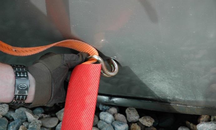
4 o o Move in on each side and place the strut under a strong, non-moving purchase point as close to the center of the vehicle as possible. Try to place the struts directly across from each other if possible. Locate attachment points for each end of the base strap. An attempt should be made to maintain a right triangle between the two legs of the strap and the vehicle. The system will be strongest when all the angles of the struts and straps are as close to right angles as possible (see Figure 4) Figure 4 - Create right angle triangles if possible o On unibody vehicles, utilize the small tie-down holes in the unibody structure as an anchor for your straps. You will need to use a towman s cluster to make the attachment (See Figure 5). Figure 5 - Towman's clusters allow attachment to the unibody holes

5 o Attach both ends of the straps and take the slack out of the straps. Once both struts are in place, tighten both straps until the struts are snug. o The vehicle is now stabilized. (see Figure 6). Figure 6 Completed two-sided stabilization The steps for placing two struts on the same side with a tie back are: o Size-up and pre-rig the struts in the same way as the previous method. o Pre-select the purchase points for the top of the strut as well as the attachment points for the straps. o Approach the vehicle and place the struts as quickly as possible. o Attach the ends of the straps to the vehicle, making sure to maintain proper angles. o Take the slack out of the straps but DO NOT tighten until the tieback is in place. o Attach a chain or strap in a triangle near the top of the vehicle. Make sure not to attach to moving parts such as suspension components (see Figure 7).
. o Use a come-along to tie back the vehicle to the anchor.")

6 Figure 7 - Chain attached to the vehicle in a triangle formation o Locate or place an anchor such as a vehicle, guardrail, utility pole, large tree, etc. If utilizing a vehicle, make SURE that the vehicle will not be moved (remove keys and mark steering wheel). o Use a come-along to tie back the vehicle to the anchor. Use a chain or strap to extend the reach of the come-along if the distance is too great (see Figure 8). Figure 8 - Come Along secured to the vehicle o Tighten the tie-back. Only apply pressure until the vehicle becomes stable. DO NOT over tighten. o Double check that the straps on the base of the struts are snug, DO NOT overtighten. o To prevent an injury on scene, a salvage cover, bunker coat, or flagging be placed on the chain to help identify the hazard. o The vehicle is now stabilized. (See Figure 9)

.")
7 Figure 9 - Completed one-sided stabilizatio The steps for stabilizing a vehicle on its roof are: o Size up the vehicle in the same manner as the previous examples. o A vehicle on its roof is usually very stable when on flat ground. If the roof is removed, the structure of the vehicle will become compromised. The weight of the vehicle may cause the chassis to drop, causing a hazard. o The vehicle will need to be supported so that the frame or unibody are held motionless throughout extrication operations (see Figure 10). o Pre-rig struts and pre-select purchase points as described above. o Place struts on the high side or end of the vehicle. Place the struts to maximize lateral (side-to-side) stability. Avoid placing struts straight up and down. o Attach stability straps. Figure 10 - Struts placed using the trunk opening for purchase points

8 o If additional lateral stability is necessary, utilize additional struts on the sides of the vehicle, secured with straps at the base. o The vehicle is stabilized (see Figure 11). Figure 11 - Completed stabilization for a vehicle on its roof. The steps for cradle stabilization with cross bracing o Initial Stabilization with step chocks or wedges o The estimated weight of the load should be quickly calculated to determine the use of the Paratech gold or gray struts o Consider the stability of the load now and when lifting o Use the front of the vehicle as the pivot point and apply wedges or picket stakes to prevent the vehicle from sliding forward o Apply a strut to each rear corner of the vehicle to create 3 points of contact Be cognizant of the placement of these struts in case of a roof removal. o Secure a chain around the bottom of the vehicle and tie them into each strut o Secure the bases of the struts with 2 ratchet straps or 2 come a longs (See Figure 12) This allows you to capture the progress with one device and lift with the other device o Once the vehicle is stabilized, you can begin the lifting sequence o Chase the load in case of strut failure o As the vehicle is lifted, the struts will suck into the vehicle and the car will want to shift and find its balance point (See Figure 13 and 14) o Consider utilizing cross bracing to better stabilize the vehicle under certain circumstances (See Figure 15) o Once the patient or object is removed, reverse order of the lift until the vehicle is returned to the ground Consider leaving the load in place after the rescue is complete. A risk vs. benefit should be used to evaluate whether we should manually lower the load or wait for the tow truck to mechanically lower the load.


9 Figure 12 Secured chain and bases of the Paratech struts Figure 13 Completed cradled stabilization


10 Figure 14 Completed cradled stabilization Figure 15 Completed cradled stabilization with cross bracing

11 H U R S T Q U I C K S T R U T S T A B I L I Z A T I O N The Kit consists of (Figure 16): o 2 Hurst Quickstruts o 2 Hand Tools o 2 Sets of Towmen s Clusters o 2 Sets of Blue Straps o Carrying Bag Locations of Quick Struts o Tower 6, Ladder 6, Rescue 2, and Rescue 6 Primarily used for vehicle stabilization, it is also suited for temporarily supporting other objects (walls, beams, etc.) Struts can be used in a tie back operation Rating per strut is 2,200 LBS The Working lengths of Quickstruts are The strut is designed to be used at an optimal installing angle of degrees. Above 35 degree angle requires securing the base plate against possible slippage up to 70 degrees. Quickstruts are for stabilization only. DO NOT use the Quickstruts for lifting of any kind! Figure 16 The Hurset Quickstrut Kit
 Figure 17 o Extend the")
")
12 Operating Quickstruts o Pull strap to get desired amount of slack (See Figure 17) Figure 17 o Extend the Quickstrut Press handle down to allow the strut to extend to its desired position (See Figure 18 and 19) Figure 18
 can be placed at the top or at the bottom per the")

")
13 Figure 19 o The base of the quick strut (marked with a red arrow) can be placed at the top or at the bottom per the manufacturer. The base down method is preferred because you have better leverage on the ratchet strap and the force applied is absorbed into the ground and not the car (See Figure 20) Figure 20 The base of the strut can be placed at the bottom or the top
 If no attachment point is available, carefully make one with a")

14 o Place the Quickstruts against the vehicle (See Figure 21) Figure 21 o Hook the strap to the vehicle To complete the triangle, hook the strap at the bottom of the vehicle (See Figure 22) If no attachment point is available, carefully make one with a halligan (This method is not advised due to the fact that the vehicle has yet to be stabilized. Striking the vehicle may shift the vehicle or further the injury of the patient or injure personnel on scene.) Figure 22 Hook the strap at the bottom of the vehicle
 Figure 23")
15 o Use caution when making purchase points to not compromise the stabilization of the vehicle (See Figure 23) Figure 23 o Use caution when making purchase points to not compromise the stabilization of the vehicle (See Figure 24) Figure 24
 Figure 25 When all")
")
16 o Securing the Quickstrut to the vehicle Take up extra slack in strap by using the hand crank (See Figure 25) Figure 25 When all the slack has been taken up, use the ratchet mechanism to tighten and secure the stabilization strut into position (See Figure 26) Figure 26
 Figure 27")
")
17 Using the hand tool, tighten the strut to the vehicle (See Figure 27) Figure 27 Lock the Quickstrut into position. Quarter turn to lock (See Figure 28) Figure 28


18 Optimum Installation angle: degrees (See Figure 29) Above 35 degrees, secure base plate against possible slippage Figure 29 Repeat the set up process for the other Quickstrut on the other side of the vehicle. Place the Quickstrut close to in line with the other Quickstrut Position the heatshield when placing strut on underside of vehicle (See Figure 30) Figure 30


19 Towmen s clusters and straps o Different ways to attach straps to the underside of the vehicle o Blue Straps (See Figure 31) Figure 31 o Towmen s Clusters (See Figure 32) Figure 32

20 W O O D C R I B B I N G S T A B I L I Z A T I O N Cribbing is essential in many extrication operations. Its most common use is to stabilize objects. Incidents that may utilize Cribbing for stabilization o Chocking Wheels o Vehicle on its side or top o Vehicle requiring extrication o Vehicle into building o Vehicle Fires o Industrial Accidents o Structural Collapse o Trench Collapse Wood selected for cribbing should be solid, straight, and free of major flaws as large knots or splits. Cribbing surfaces should be free of any paint or finish because this can make the wood slippery, especially when it is wet. The height should not be more than three times the width Wood can crush up to 20% before failure Cribbing used by LFRA o Soft wood 4 x 4 Width: 3 ½ Inches Height: 3 ½ Inches Length: 18 Inches o Untreated and Pine wood or Douglas Fir (See Figure 33) Figure 33


21 o Soft wood 4 x 2 (See Figure 34) Width: 3 ½ Inches Height: 3 ½ Inches Length: 18 Inches Figure 34 Foot Print Width of the bottom of the stack, gives you a basis on how tall your stack can be (See Figure 35) o The height should not be more than three times the width. o When setting up a crib box, it s important to ensure you have a solid foot print. Figure 35
 500 psi is when our wood starts to fail. o Estimate 15000lbs per contact point when using 6 x 6 s (5.5 x 5.5 x 500 psi) 500 psi is when our wood starts to fail. Figure 36 Over Lap Distance Four inches is the minimum that cribbing should overlap (See Figure 37) Figure 37")
22 Contact Points Points on the stack that the weight of the load is transferred to the ground (See Figure 36) o Estimate 6000lbs per contact point when using 4 x 4 s (3.5 x 3.5 x 500 psi) 500 psi is when our wood starts to fail. o Estimate 15000lbs per contact point when using 6 x 6 s (5.5 x 5.5 x 500 psi) 500 psi is when our wood starts to fail. Figure 36 Over Lap Distance Four inches is the minimum that cribbing should overlap (See Figure 37) Figure 37
23 2 x 2 Box Crib (See Figure 38) o Typically made out of 4 x 4 s but can be made out of any dimension lumber o 2 x 2 box crib made of 4 x 4 s can support 24,000lbs with all contact points covered o 2 x 2 box crib made of 6 x 6 s can support 60,000lbs with all contact points covered Figure 38 3 x 3 Box Crib (See Figure 39) o 3 x 3 box crib made of 4 x 4 s can support 48,000lbs with all contact points covered o 3 x 3 box crib made of 6 x 6 s can support 120,000lbs with all contact points covered


24 Figure 39 Box Cribbing Designs (See Figure 40 and 41) o You may need to construct these different boxes due to the situation and availability of space o Cribbing which is not square is less stable. Height to width ratio should not be greater than 18 inches Figure 40 o In this situation, the weight is limited to how much the timber can hold across a span Stack is most efficient when weight is directed straight down the stack at all contact points Figure 41
 Figure 42 Wood cribbing is")
 o Dash Lift (See Figure 44) o B-Post Blow Out")
25 When utilizing a crib box to help raise a Paratech Airbag, make sure to utilize a flat base (See Figure 42) Figure 42 Wood cribbing is also utilized for certain tactics in vehicle extrication o Miami Dade (See Figure 43) o Dash Lift (See Figure 44) o B-Post Blow Out Figure 43

26 Figure 44 Wood Cribbing Safety Concerns o Add appropriate cribbing as your lift. Chase the load o Use another piece of cribbing or tool to place cribbing, keeping your hands and body out of the fall area. o Have a stabilization plan and ensure everyone on scene is on the same page. o Never pull cribbing out from a supported load all at once. o Ensure you have enough cribbing and the right materials to get the job done safely and efficiently o Never place cribbing on top of an air bag. o Improper box crib stack Weight is limited to how much the timber can hold across a span. o Never use more than one wedge in a vertical stack. Cribbing will become unstable. Always use wedges equally for safety

27 A I R B A G S T A B I L I Z A T I O N /RA I S I N G Air bags work on a simple proven law of physics: for each pound per square inch psi of compressed air inflated into a bag, the force is multiplied over the bag s entire surface area, creating lifting force. High pressure air bags are not designed for lift height, but rather lift force. Crib underneath the bags (with a solid platform) in order to get them as close as possible to the object being lifted. Little bag, little lift, big bag, big lift Paratech Airbags are comprised of 5 components Paratech Airbags o Paratech Airbags are made from 3 layers of Neoprene covered Aramid fiber reinforcement and has the power to lift, move or shift weights up to 89 tons (Our bags can lift 53 Tons) o Paratech air bags come in two different shapes: square or rectangular Square bags offer the ability to stack bags on flat surfaces (See Figure 45), while rectangular bags (See Figure 46) provide an effective lift against linear loads and when lifting on hills or inclines Figure 45


28 Figure 46 o All Paratech Airbags have the following data molded on to the bag (See Figure 47 and 48) Model Number Lift Capacity Air Pressure Lifting Height Figure 47


29 Figure 48 o o The yellow X on the airbag marks the center of the load Never exceed 118 psi on the Paratech Airbags Paratech Controller o The Paratech Controller that we utilize at LFRA is called the Duel Deadman Controller (See Figure 49) o The shoulder strap should be rested on the operators shoulder, not put over the user s head Figure 49

 o Regulation from 135 psi to 5500 psi")
30 o The controller system also includes an Inline relief Valve (See Figure 50) LFRA trains with the inline relief valve at the bag Paratech suggests using the inline relief valve at the controller Allows for the removal of the hose from the controller without deflating the air lifting bags Paratech Pressure Regulator (See Figure 51) o Regulation from 135 psi to 5500 psi Figure 50

31 Paratech Air Hoses o The air hoses that we utilize at LFRA are 3/8 inch and 32 feet long (See Figure 52) o Paratech Air Hoses have a 300 psi capacity o When attaching the Air Hoses, ensure that locking mechanism is locked on the quick connect coupling Figure 52 Air Supply o LFRA utilizes a 30 minute Scott SCBA Cylinder to inflate the airbags
 1 21 x 15 15 Tons (118 PSI) 1 15 x 15 13.7 Tons 1 12 x 6 3.5 Tons 1 10 x 10 5.4 Tons 1 6 x 6 1.")
32 Paratech Airbags utilized by LFRA High Pressure Airbags (See Figure 53) o Tower 6 and Rescue 1 28 x Tons 2 24 x Tons 2 20 x Tons 1 21 x Tons (150 PSI) 1 21 x Tons (118 PSI) 1 15 x Tons 1 12 x Tons 1 10 x Tons 1 6 x Tons Figure 53

33 Air Bag Setup Attach the SCBA to the designated airbag lifting air pack Attach the Pressure Regulator to the SCBA cylinder Attach an air hose (preferably black) to the Pressure Regulator Attach the above air hose to the Dual Deadman Controller Attach 2 inline relief valves to the Dual Deadman Controller Attach 2 colored air hoses to the inline relief valves Attach the 2 colored air hoses to the desired Paratech Airbags Ensure that all locking mechanisms are locked on the quick connect couplings on the air hoses Pressurize the system by turning your SCBA on and set the regulator to 118 psi Completed Setup (See Figure 54) Figure 54

34 Inflating the Airbags Maximize the lifting airbag surface contact by cribbing up to what you are going to lift When using two bags for height, place the larger airbag on the bottom and DO NOT stack more than two bags. o Ensure that the air inlets on the airbag are on opposite sides Line up the X s on the airbags (See Figure 55) Figure 55 Inflate the bottom airbag until top of the airbag makes contact with the object, then inflate the top bag to achieve desired height. Depress the up green button on the Deadman Controller and the lifting airbag will inflate Chase the load as you go o Lift an inch, crib an inch with wood cribbing Inflate only until desired height or maximum pressure of 118 psi is achieved Turn the inline relief off to maintain pressure in the bag Disassembly of airbag system Don t disconnect any components of the airbag system while under pressure Depress the red down button on the Deadman Controller to deflate the airbags o Deflate the top airbag first, then the bottom airbag o Remove cribbing as you deflate and lower your object Once the bags are deflated, start at the air supply and it turn it off Depress the red and green buttons on the controller to release any pressure in the controller and supply line Check gauges, if at zero, disconnect the hoses
35 Maintenance Paratech suggests an inspection of the 5 components every 3 months and after each use Clean bags with warm water and light soap o Don t use petroleum base products to clean the airbags as they will begin to breakdown the surface of the airbag Keep the regulator, controller, inline relief valves, and hoses clear of dust, grit, and oil Dry components and return to service Check for leaks on the airbag by cleaning the bag and inflating the airbag to 30 psi o Wipe the bag down with soapy water and let stand for 10 minutes o Check for leaks and if any leaks are found, mark the leak location, and take the bag out of service. Weights of common materials Wood 45lbs per cubic foot Concrete 150lbs per cubic foot Dirt/Sand 100lbs per cubic foot Steel 490lbs per cubic foot Airbag Safety Concerns When stacking airbags, total lifting capacity is designated by the smallest bag Inflate bags slowly to prevent unwanted moving or shifting Chase the load as you go General practice is to inflate to only 50% of the bags capacity to prevent unwanted stability Never work under a load supported only by air bags Reduce a bags lifting capacity by 50% when lift is greater than 1 Never exceed the maximum air pressure of the lift bag Avoid high temperatures (220 degrees) Avoid sharp objects Never place wood between two bags Place a material or piece of plywood on top of the airbag to protect the bag and to maximize surface contact area Do not carry bags by the air inlet Stand clear of hoses and do not walk on them

36 H Y D R A - F U S I O N L I F T I N G S T R U T S Figure 56 Components Hydra-Fusion Strut o 10 ton lifting capacity with a 2:1 safety factor o 20,000lb stabilizing capacity with a 4:1 safety factor o Hydra-Fusion Struts are used in conjunction with Paratech Long-Shore, Acme-Thread, and Lock-Stroke Struts & extensions. Hydra Fusion Pump o Two stage, single action pump with 10-foot non-conductive hose, rated for 10,000 psi. BASIC SAFETY PRECAUTIONS: To avoid the possibility of serious injury or death, stay clear of the loads and keep others away. Do not exceed the rated capabilities of the HFS (Hydra-fusion Strut), pump, or hose. Control the load at all times with Stabilization Struts. *Always install Stabilization Struts first at a lower angle with respect to the ground and object being lifted; is optimal. Always perform a lift using the HFS at a angle or greater with respect to the ground and object being lifted. (Figure 57) A vertical lift using the HFS directly under a load is acceptable at 90. Make sure the HFS Lock-Collar chase the load at all times by adjusting the Lock-Collar down as the HFS is extended. The Lock-Collar should never get more than 1 away from the tube body. DO NOT rapidly drop a load supported by the HFS. Lower the load carefully by SLOWLY opening up the pump control lever. Do not use the pump hose to move attached equipment. Stress may damage the hose and fittings, which could cause personal injury and equipment failure.

37 Figure 57 Hydra-Fusion Strut and Pump operation Connect the HFS (tube end down) to a Paratech base plate and ensure the locking pin is secure. Connect a ratchet strap to opposing strut base plate to ensure there is no movement of the base plates. Select an appropriate Paratech strut or extension and connect it to the HFS. o Note One HFS can be used in combination with one strut and one extension with a combined length of 16 feet or two extensions having a maximum combined length of 3 feet. Figure 58 Install stabilization struts at degrees and attach a ratchet strap from one base plate to the other. Connect the pump hose to the HFS ensuring that the pressure is bled off the pump first. o Turn the valve controller clockwise for pressure and counter clockwise to bleed off pressure (Figure 59)

 to control the descent.")
38 Figure 59 Unlock the handle of the pump. To extend the HFS, turn the pump control valve clockwise to the closed position and work the handle up and down. o As the strut is lifting it is essential to rotate the lock collar to chase the load and ensure that the load is captured at all times, keeping the collar within one inch of the strut body. o Note The pump can be operated in two positions, horizontal or vertical (the head must be pointed down). To release pressure or lower the load, slowly open the pump control valve (turning counter clockwise) to control the descent. o Control the lock collar and chase the load keeping the collar within one inch of the tube body. (figure 60) Figure 60 After use, before disconnecting the pump hose, bleed all pressure from the system by turning the control valve counter clockwise allowing the strut to fully retract. (Figure 60)

 Controller Operation Attach a high-pressure hose from the Paratech regulator (connected to a")

39 V S K C O N T R O L L E R Figure 61 The VSK Controller is used to supply pressurized air into the stabilization struts to follow the load as it is being lifted so personnel can remain at a safe distance from the vehicle or hazard area. (Figure 61) Controller Operation Attach a high-pressure hose from the Paratech regulator (connected to a cylinder) to the inlet connector of the controller. Connect a wye to the outlet side of the controller and attach one hose to each of the struts you want to control. (figure 62) You may also connect air hoses in series to the struts you want to control utilizing wyes connected to each strut. (Figure 63) Figure 62

 o As the strut is lifting it is essential to rotate the lock collar to chase the load and ensure that the load is captured at all times, keeping the collar within one inch")
40 Figure 63 Up to four struts can be connected to one controller. Once all struts are connected, set the regulator between 50 and 200 psi. o The VSK controller reduces the output pressure to 25 psi. Turn the 90-degree shutoff valve so it is in line to allow airflow through the controller. Slide the control forward until the strut begins to extend with the load. (figure 20) o As the strut is lifting it is essential to rotate the lock collar to chase the load and ensure that the load is captured at all times, keeping the collar within one inch of the strut body. Leave the slide control at the designated position for the duration of the operation. To lower the load, slide the control back until the strut begins to lower. Figure 64

41 S T A B I L I Z A T I O N /LI F T I N G C O N S I D E R A T I O N S It may be necessary to capture the suspension of a vehicle when lifting another vehicle off of it. o Use a ratchet strap from one wheel over the hood of the car to the other wheel and tighten the strap. (This will reduce the amount of lift that must take place) (Figure 65) Figure 65 There are several ways to attach a strut for stabilizing or lifting a vehicle. o Finding a strong purchase point for the strut tip to connect directly to the vehicle. (figure 66) o Using chains to sling or cradle the load. Attach a chain to a chain tip on one end of a strut sling it under the load and attach it to another chain tip on a strut on the other side of the vehicle. (figure 67) Ensure that the struts are directly across from each other and are at the same extension.


42 Figure 66 Figure 67 It may be necessary to marry two vehicles together to ensure the best stabilization possible. o Connect one or more ratchet straps to structural components of both vehicles to secure them to one another. (figure 68)


43 Figure 68 If there is not an effective connection point on a vehicle to secure ratchet straps to the struts, pickets can be used to immobilize the strut bases. (figure 69) Figure 69 R E F E R E N C E I N F O R M A T I O N NFPA Extrication and Cribbing PowerPoint by Chris Beswick Fire.jbpub.com Chapter 8 Vehicle Stabilization Cribbing Basics PowerPoint by Brad Delano University of Extrication by Ron Moore
Tech. Services: (800) Fax: (800) Order Entry: (800) Fax: (800) MODEL D INFLATABLE JACKS
 Fax: (800) Order Entry: (800) Fax: (800) MODEL D INFLATABLE JACKS") SPX Corporation 5885 11th Street Rockford, IL 6119-3699 USA Internet Address: http://www.powerteam.com Tech. Services: (8) 477-8326 Fax: (8) 765-8326 Order Entry: (8) 541-1418 Fax: (8) 288-731 Parts List
SPX Corporation 5885 11th Street Rockford, IL 6119-3699 USA Internet Address: http://www.powerteam.com Tech. Services: (8) 477-8326 Fax: (8) 765-8326 Order Entry: (8) 541-1418 Fax: (8) 288-731 Parts List
WHEEL-RESTING SIDE LIFT
 R EQ U I R ED EQ U I P M ENT WHEEL-RESTING SIDE LIFT 1 Res-Q-Jack Strut 1 Res-Q-Jack Lifting Jack 1 Chain & Hook Assembly 3 Ratchet Strap with Wire Hooks 4 Clusters any necessary cribbing, chocks, stakes,
AIR LIFTINGBAG OPERATIONGUIDE. BasicSafelVPrecautions Equipment Description OperatingInstructions - Applications.
 PARATECH@ AIR LIFTINGBAG OPERATIONGUIDE " BasicSafelVPrecautions Equipment Description OperatingInstructions - Applications. General,Cleaning& Inspection - - - - - -- Basic Safety Precautions 1. Regardless
Air Lifting Bags MAXIFORCE AIR LIFTING BAGS. Maximum Force Where You Need It Most! What to look for when selecting a lift bag system.
 Air Lifting Bags Breathing Air Systems MAIFORCE AIR LIFTING BAGS Maximum Force Where You Need It Most! The Maxiforce Air Lifting Bag is a thin, strong, molded envelope. It is made from a Neoprene covered
161-5 Series High Pressure Flat Form Lift Bag Instruction Manual
 161-5 Series High Pressure Flat Form Lift Bag Instruction Manual Page 1 of 14 CONTENTS Preliminary remarks... 2 Safety instructions... 3 Lifting capacity performance... 4 Increasing lifting height and
PETERSEN 161-SERIES HIGH PRESSURE LIFTING AIR BAGS OPERATING INSTRUCTIONS WARNING!
 PETERSEN 161-SERIES HIGH PRESSURE LIFTING AIR BAGS OPERATING INSTRUCTIONS WARNING! Read and understand instructions before using Petersen Plugs. Failure to comply may result in property damage, serious
Model 7989T Steel Pipe Squeezer Sch. 40 & Sch. 80. Operations Manual
 10-12 Steel Pipe Squeezer Sch. 40 & Sch. 80 Operations Manual 1.0 Introduction This manual is issued as a basic operation manual covering the Regent Model 7989T, Pipe Squeezer and Pump as manufactured
II-28 STOKES BASKET OPERATIONS
 1 II-28 STOKES BASKET OPERATIONS Anchor Slings- (2) high strength nylon webbing straps with D-rings on both ends used to set an anchor. Max working load of 10,000 lbs. Bight- Element of knot formed by
LEAK SEALING SYSTEMS
 OPERATION MANUAL FOR LEAK SEALING SYSTEMS 04 FEB 2016 PN 22-891709 Paratech Incorporated Headquarters Paratech Europe, Branch of Paratech Inc. P.O. Box 1000, Frankfort, IL 60423 USA P.O. Box 174, 5260
High-Pressure Heavy Lifting Air Bags & Accessories
 High-Pressure Heavy Lifting Air Bags & Accessories High Pressure Heavy Lifting Bags for lifting the heaviest loads; up to 74 US tons. Use when maximum lifting force is needed in low clearance situations.
TABLE OF CONTENTS. 14 Operating Instructions Load vs. Contact
 Page TABLE OF CONTENTS 3 Part Identification 8 Inspection and Assembly 9 Assembly Instructions 10 Rules for Safe Operation 12 Operating Instructions 14 Operating Instructions Load vs. Contact 15 Care &
PLEASE READ AND UNDERSTAND THIS MANUAL BEFORE USING LIFTING BAGS
 PLEASE READ AND UNDERSTAND THIS MANUAL BEFORE USING LIFTING BAGS PNEUMATIC HIGH PRESSURE HEAVY LIFTING BAGS SAFETY, OPERATION AND MAINTENANCE INSTRUCTIONS NON-COMPLIANCE WITH INSTRUCTIONS AND WARNINGS
Instruction Sheet. LB Series Lifting Bags CA Series Lifting Bag Controllers. L2753 Rev. B 01/ IMPORTANT RECEIVING INSTRUCTIONS 2.
 Instruction Sheet POWERFUL SOLUTIONS. GLOBAL FORCE. LB Series Lifting Bags CA Series Lifting Bag s L2753 Rev. B 01/09 Index: English........................................1-12 Français......................................13-24
ModelsEZU-15 & EZU-15-R. BISHAMON INDUSTRIES CORPORATION 5651 East Francis Street Ontario, California 91761, USA (909) (800)
 (800)") UP P n e u m a t i c ModelsEZU-15 & EZU-15-R BISHAMON INDUSTRIES CORPORATION 5651 East Francis Street Ontario, California 91761, USA (909) 390-0055 (800) 231-3187 Table of Contents GETTING STARTED......................................
UP P n e u m a t i c ModelsEZU-15 & EZU-15-R BISHAMON INDUSTRIES CORPORATION 5651 East Francis Street Ontario, California 91761, USA (909) 390-0055 (800) 231-3187 Table of Contents GETTING STARTED......................................
310 SERIES TILT-TO-LOAD ROTATOR. The Specialist In Drum Handling Equipment
 OPERATOR S MANUAL FOR MORSE TILT-TO-LOAD DRUM ROTATOR SAFETY INFORMATION: While Morse Manufacturing Co. drum handling equipment is engineered for safety and efficiency, a high degree of responsibility
INDEX. Specifications 1. Important Safety Precautions 2. Operating Instructions 3, 4. Optional Extras (Meal Tray & Footrest) 5.
 5.") INDEX Specifications 1 Important Safety Precautions 2 Operating Instructions 3, 4 Optional Extras (Meal Tray & Footrest) 5 Air System 6 Service & Maintenance 7 Warranty / Service Contract 8 SPECIFICATIONS
INDEX Specifications 1 Important Safety Precautions 2 Operating Instructions 3, 4 Optional Extras (Meal Tray & Footrest) 5 Air System 6 Service & Maintenance 7 Warranty / Service Contract 8 SPECIFICATIONS
LOW ANGLE ROPE RESCUE OPERATIONAL
 Scope: This chapter serves as an introduction to anchor systems. Terminal Learning Objective (TLO): At the end of this chapter, the student will be aware of anchor selection and anchor system construction.
INSTALLATION, OPERATION AND SERVICE MANUAL ABS AIR BAG LIFT
 INSTALLATION, OPERATION AND SERVICE MANUAL ABS AIR BAG LIFT P.O. Box 1058 1058 West Industrial Avenue Guthrie, OK 73044-1058 405-282-5200 FAX: 405-282-8105 www.autoquip.com Item # 830ABS Version 1.0 07/2001
S P E C I A L O P E R A T I O N S : S W I F T W A T E R B O A T O P E R A T I O N S ( 1. 1 ) T A S K S K I L L D E S C R I P T I O N A N D D E T A I L
 T A S K S K I L L D E S C R I P T I O N A N D D E T A I L") S P E C I A L O P E R A T I O N S : S W I F T W A T E R B O A T O P E R A T I O N S ( 1. 1 ) Developed by: Jason Tanner October 2015 T A S K S K I L L D E S C R I P T I O N A N D D E T A I L Swiftwater
S P E C I A L O P E R A T I O N S : S W I F T W A T E R B O A T O P E R A T I O N S ( 1. 1 ) Developed by: Jason Tanner October 2015 T A S K S K I L L D E S C R I P T I O N A N D D E T A I L Swiftwater
Shoreline Cantilever Lift 2500lb Capacity Models: (108" inside width) - Part # (120" inside width) - Part #
 - Part # (120 inside width) - Part #") Shoreline Cantilever Lift 2500lb Capacity Models: 25108 (108" inside width) - Part # 1017402 25120 (120" inside width) - Part # 1017403 1. 2. 3. 4. 5. CAUTION - PUT SAFETY FIRST Before attempting to install
Shoreline Cantilever Lift 2500lb Capacity Models: 25108 (108" inside width) - Part # 1017402 25120 (120" inside width) - Part # 1017403 1. 2. 3. 4. 5. CAUTION - PUT SAFETY FIRST Before attempting to install
Chapter 27. Gaining Access. Learning Objectives. Learning Objectives 9/18/2012. Describe purpose of extrication. Discuss role of EMT in extrication
 Chapter 27 Gaining Access Learning Objectives Describe purpose of extrication Discuss role of EMT in extrication Identify what equipment for personal safety is required for EMT Define fundamental components
TOPIC: EVALUATING FIREFIGHTER PROFICIENCY MATERIALS: PERSONAL PROTECTIVE CLOTHING AS REQUIRED FOR EACH EVOLUTION
 1 MFRI Drill of the Month INSTRUCTOR GUIDE TOPIC: EVALUATING FIREFIGHTER PROFICIENCY LEVEL OF INSTRUCTION: TIME REQUIRED: SIX HOURS MATERIALS: PERSONAL PROTECTIVE CLOTHING AS REQUIRED FOR EACH EVOLUTION
Island Hopper Gator Monster Head & Tail Water Trampoline Attachments
 Island Hopper Gator Monster Head & Tail Water Trampoline Attachments Aqua Sports Technology 11859 Lakeshore North, Auburn, CA 95602 530 268-7310 www.watertrampolines.com Table of Contents Introduction.....2
IMPORTANT WARNING SOUL PAD (2X) PAD STRAP (4X) S.U.P. BRAH (1X) KEYS (2X) RIPCORD (2X) HOOK (2X) NOSE/TAIL STRAP (2X)
 PAD STRAP (4X) S.U.P. BRAH (1X) KEYS (2X) RIPCORD (2X) HOOK (2X) NOSE/TAIL STRAP (2X)") SOUL PAD (2X) PAD STRAP (4X) S.U.P. BRAH (1X) KEYS (2X) HOOK (2X) RIPCORD (2X) NOSE/TAIL STRAP (2X) IMPORTANT WARNING IT IS CRITICAL THAT ALL YAKIMA RACKS AND ACCESSORIES BE PROPERLY AND SECURELY ATTACHED
SOUL PAD (2X) PAD STRAP (4X) S.U.P. BRAH (1X) KEYS (2X) HOOK (2X) RIPCORD (2X) NOSE/TAIL STRAP (2X) IMPORTANT WARNING IT IS CRITICAL THAT ALL YAKIMA RACKS AND ACCESSORIES BE PROPERLY AND SECURELY ATTACHED
User Instructions 1789 Parapet Wall Anchor
 User Instructions 1789 Parapet Wall Anchor This manual is intended to meet the Manufacturer Instructions as required by ANSI Z359.1 and should be used as part of an employee training program as required
MAXIFORCE AIR LIFTING BAG SYSTEMS
 OPERATION, PREVENTIVE MAINTENANCE AND PARTS SUPPORT MANUAL FOR MAXIFORCE AIR LIFTING BAG SYSTEMS PARATECH INCORPORATED P.O. BOX 1000 1025 LAMBRECHT ROAD FRANKFORT, ILLINOIS 60423-7000 TELEPHONE (815) 469-3911
Assembly Instructions. -Cantilever Boat Lifts
 Assembly Instructions -Cantilever Boat Lifts Winch Instruction Page Safety Information 1. The winch is built for the multipurpose of hauling and lifting operations. It is not to be used as a hoist for
General Information. NTA607HD Lift Assist Adjustments. Tools Required. Work Location. Notations and Conventions U B F D R B F L
 Great Plains Manufacturing, Inc. 1 NTA607HD Lift Assist Adjustments Null4: When you see this symbol, the subsequent instructions and warnings are serious - follow without exception. Your life and the lives
Transfer Chain (SA-1002) & Adjustable I-Beam Clamp (SA-1039 or SA-1040) Operating Instructions
 & Adjustable I-Beam Clamp (SA-1039 or SA-1040) Operating Instructions") Transfer Chain (SA-1002) & Adjustable I-Beam Clamp (SA-1039 or SA-1040) Operating Instructions SPIDER Page 1 of 8 702127 Rev A Using Transfer Chain with Adjustable I-Beam Clamp Safety Notes Do not use
Transfer Chain (SA-1002) & Adjustable I-Beam Clamp (SA-1039 or SA-1040) Operating Instructions SPIDER Page 1 of 8 702127 Rev A Using Transfer Chain with Adjustable I-Beam Clamp Safety Notes Do not use
STYLE 3414/3416 & 3421/3423 Apollo Monitor with Foldaway Legs OPERATING & MAINTENANCE INSTRUCTIONS
 STYLE 3414/3416 & 3421/3423 Apollo Monitor with Foldaway Legs OPERATING & MAINTENANCE INSTRUCTIONS The Akron Style 3414/3416 & 3421/3423 Apollo Monitor is designed to provide efficient trouble-free operation
Instruction Manual. PE-25/32/37 Tapping Machines. POLYTAPP Valves
 Instruction Manual PE-25/32/37 Tapping Machines & POLYTAPP Valves Nov 2016, Revision 2 Document Number 3000111 2 M.T. Deason Company, Inc. PO Box 101807 Birmingham, AL 35210 Phone: 205 956 2266 Fax: 205
20 Ton SD Shop Press Operating Instructions
 20 Ton SD Shop Press Operating Instructions MODEL NO. 850SD Hazard Symbols Used in the Manuals This manual includes the hazard symbols defined below when the operations or maintenance job involves a potential
OPERATING INSTRUCTIONS FOR THE MODEL 85B
 OPERATING INSTRUCTIONS FOR THE MODEL 85B SAFETY PRECAUTIONS FOR THE MODEL 85B System Under Pressure: Shut off air supply and disconnect air hose before disassembling or disconnecting parts. Flying Debris:
OPERATION MANUAL DMI 16-LIGHT LIGHT TOWER ALSO AVAILABLE ONLINE AT DMI-LT.COM
 OPERATION MANUAL DMI 16-LIGHT LIGHT TOWER ALSO AVAILABLE ONLINE AT DMI-LT.COM 1 You have purchased a very high quality piece of equipment that should provide years of useful life. Following the instructions
Pressure Relief Valve Instruction Manual
 CVR3-M0_062017 Pressure Relief Valve Instruction Manual MODEL: CVR3 SFA Companies 10939 N. Pomona Ave. Kansas City, MO 64153 Tel: 888-332-6419 * Fax: 816-448-2142 E-mail: sales@bvahydraulics.com Website:
PNEUMATIC MEDIUM PRESSURE HEAVY LIFTING BAGS
 PLEASE READ AND UNDERSTAND THIS MANUAL BEFORE USING SAVA LIFTING BAGS PNEUMATIC MEDIUM PRESSURE HEAVY LIFTING BAGS & INFLATION ACCESSORIES SAFETY, OPERATION AND MAINTENANCE INSTRUCTIONS NON-COMPLIANCE
On the Go Swing System Instruction Manual
 On the Go Swing System Instruction Manual WARNING READ ENTIRE MANUAL BEFORE USE. THIS SWING IS NOT A TOY. THIS SWING IS ONLY TO BE USED BY TRAINED PERSONNEL, SUCH AS AN OCCUPATIONAL THERAPIST, PHYSICAL
Ladies Shopper Bike Assembly Manual 28C03
 Ladies Shopper Bike Assembly Manual 28C03 Ecosmo Ltd 1 Know your bike 1. Wheel 2. Rear Derailleur 3. Chain 4. Crank Set 5. Pedal 6. Seat Quick Lock 7. Saddle and Post 8. Frame 9. Front Light 10. Front
Developed by Engineers Alex Klinger and Shelby Vrem November 2015
 TRENCH RESCUE (1.1) Developed by Engineers Alex Klinger and Shelby Vrem November 2015 TASK SKILL DESCRIPTION AND DETAILS Task: To safely and effectively rescue a patient out of a trench environment. Mode
75 Ton SD Shop Press Operating Instructions
 75 Ton SD Shop Press Operating Instructions MODEL NO. 856SD Hazard Symbols Used in the Manuals This manual includes the hazard symbols defined below when the operations or maintenance job involves a potential
REV0709. Parts List. Hydraulic Cylinder Model MODEL C SINGLE-ACTING, SPRING RETURN HYDRAULIC CYLINDER. Max. Capacity: 55.2 Tons at 10,000 PSI
 REV0709 Parts List Hydraulic Cylinder Model 10312 MODEL C SINGLE-ACTING, SPRING RETURN HYDRAULIC CYLINDER Max. Capacity: 55.2 Tons at 10,000 PSI REV0709 Item No. Part No. No. Req d Description 1 10606
Performance Examination 4100 Sub JAC Handbook
 TOPIC: CATEGORY: JAC PERFORMANCE EXAM 24 Extension Ladder POINTS POSSIBLE: 100 TIME ALLOWED: 6 Minutes BEHAVIORAL OBJECTIVE: Condition: Behavior: Standard: An engine with a MMR SCBA mounted in a breathing
Exercise 2-3. Flow Rate and Velocity EXERCISE OBJECTIVE C C C
 Exercise 2-3 EXERCISE OBJECTIVE C C C To describe the operation of a flow control valve; To establish the relationship between flow rate and velocity; To operate meter-in, meter-out, and bypass flow control
S-60-TO : 1 ton tower system INSTRUCTION MANUAL
 S-60-TO : 1 ton tower system INSTRUCTION MANUAL LIVE SYSTEMS bvba Mandellaan 282 8800 B-Roeselare Tel: +32(0)51 69 38 14 Mobile : +32 (0) 495 24 24 67 e-mail: ricky@livesystems.be BTW : 0859.636.665 1
8MAY15 US RACK, Inc Falcon Drive, Madera, CA
 8MAY15 US RACK, Inc. - 2850 Falcon Drive, Madera, CA 93637-559-661-3050 INSTRUCTIONS for Bedrail-mounted MOTORCYCLE RACK, Model 2001-4TRA WARNING: Do NOT attempt to install or use this rack without following
Fall Protection Checklist. Guardrail System
 Fall Protection Checklist Location/Department: Date of Inspection: Inspectors: Corrective Actions: Work order/memos were issued: Yes No Date issued: In accordance with the MIOSHA and OSHA standards the
Booster Pump PB4-60 Replacement Kits
 Booster Pump PB4-60 Replacement Kits FOR YOUR SAFETY - This product must be installed and serviced by a contractor who is licensed and qualified in pool equipment by the jurisdiction in which the product
SERIES 2 RAMP OWNER S MANUAL TOOLS REQUIRED: BEFORE YOU BEGIN... Read and understand these instructions before beginning a ramp setup.
 SERIES 2 RAMP OWNER S MANUAL BEFORE YOU BEGIN... Read and understand these instructions before beginning a ramp setup. Use caution and care for your back when lifting, pushing, pulling, folding or unfolding
CHAINLESS ANCHORING SYSTEM USER MANUAL
 CHAINLESS ANCHORING SYSTEM USER MANUAL Introduction..................................................... 1 Setting up the Chainless Anchoring System............................ 4 Set up Procedure............................................
WARNING! DO NOT THROW AWAY THESE INSTRUCTIONS! READ AND UNDERSTAND BEFORE USING EQUIPMENT!
 Guardian Fall Protection Kent, WA 800-466-6385 www.guardianfall.com GENERAL SYSTEM SELECTION CRITERIA: Selection of fall protection shall be made by a Competent Person. All fall protection equipment shall
Installation, Operation & Maintenance Manual for Flo-Max Coupler Bracket Model FM150
 Installation, Operation & Maintenance Manual for Flo-Max Coupler Bracket Model FM150 January 2013 Form FVC 084 - Rev 02 IMPORTANT: KEEP THIS DOCUMENT WITH THE PRODUCT UNTIL IT REACHES THE END USER. 1.
APPENDIX F Rail Chocks Quick Reference Guide
 COMMON CHOCK TYPES Manuf. Chock Description Railcar Type Profile Tie-Down Type Chocks per Vehicle Strap 1 Holden Grate Lock Bi-Level Standard Grating 4 No 2 Holden Low-Profile Grip Lock Bi-Level Low Grating
Study & Manipulative Training Guide
 Study Manipulative Training Guide What is the XCOLLAR? The XCollar is a complete Cervical Spine Splinting System designed especially for EMS. It ensures the highest level of patient safety while significantly
User Instructions 1790 Rail Anchor
 User Instructions 1790 Rail Anchor This document is intended to meet the Manufacturer s Instruction requirements as stated by ANSI Z359.1, and should be used as part of an employee training program as
REL-510H WARNING NOTICE 12 TON SINGLE ACTING REMOTE HYDRAULIC CRIMPING HEAD
 OPERATORS ORS GUIDE REL-510H 12 TON SINGLE ACTING REMOTE HYDRAULIC CRIMPING HEAD Compatible with U style and RELIABLE R12 shell type 12 ton compression dies. RELIABLE EQUIPMENT & SERVICE CO., INC. 92 Steamwhistle
Charmborough Bells Risk Assessment and Method Statement
 Charmborough Bells Risk Assessment & Method Statement Charmborough Bells Risk Assessment and Method Statement Introduction This risk assessment and method statement has been prepared to outline the procedures
600 / 600FC OWNER'S MANUAL
 PROGRESSION 600 / 600FC OWNER'S MANUAL Issue 2 / Version E - Dec. 10, 1997 Copyright 1997 GAMMA Sports - All Rights Reserved PROGRESSION 600 / 600FC OWNER'S MANUAL TABLE OF CONTENTS PAGE 1... WARRANTY
THE OWNER'S MANUAL IS IN TWO VOLUMES: VOLUME 2 TECHNICAL SPECIFICATIONS - ASSEMBLY PROCEDURE ZODIAC
 CAUTION NOTICE: CAREFULLY READ THIS MANUAL BEFORE OPERATING YOUR BOAT. THIS OWNER S MANUAL IS IN TWO VOLUMES THAT MUST BE KEPT TOGETHER. THE OWNER'S MANUAL IS IN TWO VOLUMES: - VOLUME 1 DEALS WITH OPERATING
Instant Garage 20' x 12' 3" x 8' 3"
 Instant Garage 20' x 12' 3" x 8' 3" Assembly Instructions Description Model # Instant Garage 20' x 12' 3" x 8' 3" - Grey CIG 1220 3503502 Recommended Tools OR THIS IS A TEMPORARY STRUCTURE AND NOT RECOMMENDED
POWER LIFT LOW PRESSURE LIFTING BAGS. Instructions for use
 POWER LIFT LOW PRESSURE LIFTING BAGS Instructions for use The system of WEBER-HYDRAULIK low pressure lifting bags of the 0.5 and 1.0 bar series is used particularly for rescuing persons captured in various
BRONZE BUSHING REPLACEMENT PROCEDURE DN345 & NL450C
 1 BRONZE BUSHING REPLACEMENT PROCEDURE V.2 12/3/2014 DN345 & NL450C 2 Safety Instructions Removing Walking Beams 3 1. Position spreader on a flat concrete surface capable of supporting weight of spreader
MODEL SWH10 1,000 LB CAPACITY SWIVEL HOIST
 MODEL SWH10 1,000 LB CAPACITY SWIVEL HOIST PARTS BREAKDOWN AND OPERATING MANUAL Copyright 2007, Arcan Professional Tools Rev: 05/15/07 This operating manual contains important safety information. Read
INSTALLATION INSTRUCTIONS. Parts List. Tools Required. Before You Begin. Installation. Customer Information BICYCLE ATTACHMENT JUL.
 INSTALLATION INSTRUCTIONS JUL. 2006 Parts List Bicycle attachment Key plates (2) Tools Required Phillips screwdriver Flat-tip screwdriver Before You Begin Customer Information This Bicycle Attachment is
AIR/OVER HYDRAULIC JACK 20 TON
 AIR/OVER HYDRAULIC JACK 0 TON 4487 ASSEMBLY AND OPERATING INSTRUCTIONS 349 Mission Oaks Blvd., Camarillo, CA 930 Visit our Web site at http://www.harborfreight.com Copyright 999 by Harbor Freight Tools.
SIGNATURE DEF REELS Models: Bare Reel Reel Reel Reel
 SERVICE BULLETIN SB2023 Rev C 7/11 SIGNATURE DEF REELS Models: 2400-006 Bare Reel 2400-007 16 Reel 2400-008 20 Reel 2400-009 30 Reel Thoroughly read and understand this manual before installing, operating
HYDRAULIC PUNCH DRIVER 38456, 38520, 7306 / 7306SB, 7310 / 7310SB, 7506, 7606SB, 7610SB, 7625 / 7625Pg / 7625PgSB, 7646 / 7646Pg / 7646PgSB
 INSTRUCTION MANUAL HYDRAULIC PUNCH DRIVER 38456, 38520, 7306 / 7306SB, 7310 / 7310SB, 7506, 7606SB, 7610SB, 7625 / 7625Pg / 7625PgSB, 7646 / 7646Pg / 7646PgSB Read and understand all of the instructions
3/4 SafeClaw Anchorage Connectors
 Operations and Instruction Manual Model #4075 Portable Concrete Anchorage Connector ANSI Z359.1-07 5,000 lbs / 22kn OHSA 1910.66 & 1926.502 Effective: 01/2012 Expires: 01/2022 IM-0049 REVA 3/4 SafeClaw
SKED-EVAC Tripod Instructions
 Skedco, Inc. Web Site: http://www.skedco.com E-mail: skedco@skedco.com P.O. Box 3390 Tualatin, Oregon 97062 USA Phone (503) 691-7909 FAX (503) 691-7973 SKED-EVAC Tripod Instructions FEATURES The Sked-Evac
2012 K9100 COMPACT Worldwide Cycling Solutions Through Creative Innovations.
 Home Instruction Sheet Step-1Please check for any missing parts. Model K9100 COMPACT (Basic AirCaddy) aircaddy web page 20 04/03/12 98% (1) T3230-00 METAL WHEEL TRUCK Model K8350 (Aircraft Kit) (Optional)
On the Go Swing System Instruction Manual
 On the Go Swing System Instruction Manual WARNING READ ENTIRE MANUAL BEFORE USE. THIS SWING IS NOT A TOY. THIS SWING IS ONLY TO BE USED UNDER ADULT SUPERVISION. CONSULT WITH A CHILD S THERAPIST ON HOW
2,500/4,000 LB Easy Riser Vertical Cable Feighner Lift
 2,500/4,000 LB Easy Riser Vertical Cable Feighner Lift CAUTION - PUT SAFETY FIRST 1. Before attempting to install or operate this lift, study and fully understand the proper operating procedures and safety
4 ANGLE GRINDER MODEL NO: CAT 52 PART
 4 ANGLE GRINDER 4 ANGLE GRINDER MODEL NO: CAT 52 PART No: 3110685 OPERATION & MAINTENANCE INSTRUCTIONS 0807 Fig.1 SPECIFICATIONS Model:...CAG52 Part Number:...3110685 Rated Wheel...Capacity: 4 x 1/4 (type
Products For The. Fire & Emergency Services. Cintec International Limited
 Products For The Fire & Emergency Services Cintec International Limited Waterwall Isolation Units Acetylene Isolator Specifications: External Height External Width External Depth Internal Height Internal
Instruction sheet for Hydraulic Cylinder
 Oper at or smanual 1088710891 Hydr aul i ccyl i nder s Instruction sheet for Hydraulic Cylinder NOTE PLEASE READ AND FOLLOW THIS INSTRUCTION BEFORE YOU USE Yellow Jackit CYLINDERS. Carefully inspect all
! CAUTION! ! WARNING! General Information
 Great Plains Mfg., Inc. Installation Instructions Used with: 2SF24, 24-Foot Two-Section Drill General Information Two-Section, Hydraulic Folding Marker 2SF30, 30-Foot Two-Section Drill 2SBM30, 30-Foot
accidents which arise due to non-observance of these instructions and the safety information herein.
 3 GALLON PANCAKE COMPRESSOR Model: 50959 CALIFORNIA PROPOSITION 65 WARNING: You can create dust when you cut, sand, drill or grind materials such as wood, paint, metal, concrete, cement, or other masonry.
Pontoon Slide Owner s Manual
 Pontoon Slide Owner s Manual Introduction Water sports can be safe and fun for all levels of enthusiasts. The Owner s Manual is presented to enhance your enjoyment of the sport. It is intended to alert
Parts: Included in the parts box: Inner Rear Tire Tray. Inner Front Tire Tray. Trail Doc Clamp. Pivot Assembly. Trail Doc Post.
 NV 2.0 2 Parts: Outer Front Tire Tray Inner Front Tire Tray Outer Rear Tire Tray Inner Rear Tire Tray Pivot Assembly Trail Doc Clamp Trail Doc Post Included in the parts box: 6mm Allen Wrench M6 Lock Washer
MANUAL BE SERIES Test Benches
 The CustomCrimp Manual BE Series Test Benches are designed with features that make proof and burst testing of hydraulic hose assemblies a quick and easy procedure. CUSTOMIZED AND SPECIAL DESIGN BENCHES
Misaligned Folds Paper Feed Problems Double Feeds Won t Feed FLYER Won t Run iii
 Operator s Manual Table of Contents Operator Safety... 1 Introduction... 2 Unpacking and Setup... 3 Unpacking... 3 Setup... 4 FLYER Overview... 5 FLYER Diagram... 5 Capabilities... 5 Control Panel... 6
Operations and Instruction Manual Might Swivel Model # Concrete and Steel Anchorage Connector ANSI Z ,000 lbs / 44kn
 Operations and Instruction Manual Might Swivel Model # 00238 Concrete and Steel Anchorage Connector ANSI Z359.1 10,000 lbs / 44kn Description: Zinc plated forged heat treated steel, Special design gives
30T A/Manual Hydraulic Shop Press
 30T A/Manual Hydraulic Shop Press Operation Manual 1 1. Important Information 1.1 Safety Information 1.1.1 Hazard Symbols Used in the Manuals This manual includes the hazard symbols defined below when
L-23 Super Blanik Rigging (assembly/disassembly) Guide Maj Carl Kerns
 Guide Maj Carl Kerns") L-23 Super Blanik Rigging (assembly/disassembly) Guide Maj Carl Kerns The L-23 Blanik is a difficult Sailplane to rig (assemble). The wings are heavy and are secured via a single
L-23 Super Blanik Rigging (assembly/disassembly) Guide Maj Carl Kerns The L-23 Blanik is a difficult Sailplane to rig (assemble). The wings are heavy and are secured via a single
Inflatable Dock Slide Owner s Manual
 Inflatable Dock Slide Owner s Manual Introduction Water sports can be safe and fun for all levels of enthusiasts. The Owner s Manual is presented to enhance your enjoyment of the sport. It is intended
REL-46 WARNING NOTICE 15 TON SINGLE ACTING REMOTE HYDRAULIC CRIMPING HEAD. Compatible with RELIABLE R15 and P Style dies. REL-46 Manual
 OPERATORS ORS GUIDE REL-46 15 TON SINGLE ACTING REMOTE HYDRAULIC CRIMPING HEAD Compatible with RELIABLE R15 and P Style dies. RELIABLE EQUIPMENT & SERVICE CO., INC. 301 Ivyland Road Warminster, PA 18974
INSTRUCTION AND PARTS MANUAL MODELS #13000 TO HYDRAULIC CYLINDERS
 INSTRUCTION AND PARTS MANUAL MODELS #13000 TO 13080 HYDRAULIC CYLINDERS Form No. 102397-AME Operating Instructions for: Single-acting and Double-acting Rams and Cylinders (Various Capacity) DEFINITIONS
Vibration isolation system 1VIS10W. User manual
 Vibration isolation system 1VIS10W User manual Standa 2014 Table of contents 1. General information 3 1.1. Introduction 3 1.1.1. Safety 5 1.2. Location of the table 5 1.3. Air supply requirements 5 2.
MANITOWOC MODEL TON CAPACITY
 LIFTING CHARTS - Crawler Cranes ANITOWOC ODEL - TON CAPACITY BOO RIGGING GUIDE ODEL # HEAVY LIFT BOO Table of Contents General... Assist Crane Requirements... Accessing Parts... Installation and Removal
Pontoon Slide Owner s Manual
 Pontoon Slide Owner s Manual WWW.RAVESPORTS.COM Copyright 2018 All rights reserved. No part of this publication may be reproduced or transmitted in any form or by any means, electronic or mechanical, including
C - SERIES. Height Adjustable Portable Goal Supports. Installation & Owner s Instructions C1000 C2000. Made in the USA
 C - SERIES Height Adjustable Portable Goal Supports C1000 C2000 Installation & Owner s Instructions Made in the USA This manual explains the proper installation, operation, and maintenance of your Schutt
RAVE SUP STAND UP PADDLE BOARD User Guide/Owner s Manual
 RAVE SUP STAND UP PADDLE BOARD User Guide/Owner s Manual ! W A R N I N G This product is not a lifesaving device. Always wear a nationally approved personal floatation device when using this product. Not
SERVICE MANUAL MODEL BA050BMST BREATHING AIR PANEL
 www.modsafe.com SERVICE MANUAL MODEL BA050BMST BREATHING AIR PANEL WARNING: Do not attempt to operate this equipment without first reading and understanding the service manual enclosed with this device.
Safety, Operating and Maintenance Manual. TRAIN Rat DS9-TRAIN
 Safety, Operating and Maintenance Manual TRAIN Rat DS9-TRAIN Industry s first air powered entry tool! Quickly, quietly and reliably opens passenger train doors! Introducing the TRAIN Rat. This innovative
Approved Models. Important. Contents
 Cribbing Instructions First Edition Fifth Printing Important Plywood cribbing may be used to provide a level surface for safe boom operation. This instruction manual contains specifications for site constructed
U.S. CONCRETE, INC. SAFETY POLICY and PROCEDURE MANUAL
 SAFE -14 Page 1 of 8 U.S. CONCRETE, INC. SAFETY POLICY and PROCEDURE MANUAL FUNCTION Safety TOPIC Hotwork Permit Program OBJECTIVE(S): GENERAL POLICY: To provide a work atmosphere that is conducive to
PART NUMBER: E361SXA200 DESCRIPTION: KAYAK CARRIER
 A KIT CONTENTS: : Plug 16x Long Carriage Bolt 4x Hex Key 4x Button Head Screw 4x Pad Strap BASE Over-Molded Wrench 1x SnapAround 4x 1/5 : Important Notes: Minimum crossbar spread of 24". If spread is less
EUROBUNGY-TRAMPOLINE
 EUROBUNGY-TRAMPOLINE Set-up instructions of the new model 2004-2010 Photos are taken with the long and short Trailer WARNING for EUROBUNGIES without hydraulic rams There is a potential risk that a pole
35 TON HYDRAULIC PUNCH WARNING
 OPERATORS GUIDE REL-35T-PNC 35 TON HYDRAULIC PUNCH NOTICE Sizes, weights and tool specifications listed in this manual are subject to change without notice. Please consult factory for information and updates.
Operation Manual Guillotine Cutter RC-5
 Operation Manual Guillotine Cutter RC-5 Technical Specifications General Safety/Operating Instructions Using the Guillotine Cutter/Crimper Blade Change Instructions Maintenance Instructions This is a detailed
GCI CYLINDER INVERTER
 GCI CYLINDER INVERTER GALISO CYLINDER INVERTER INSTRUCTION MANUAL MANUAL NUMBER 21-11-1506 Issued May 2012 Copyright 2012 - Galiso, Incorporated 22 Ponderosa Ct., Montrose, CO 81401 (970) 249-0233 (800)