The owner and all operators must be familiar with all of the operational guidelines laid out within this manual.
|
|
|
- Cuthbert Townsend
- 5 years ago
- Views:
Transcription

1
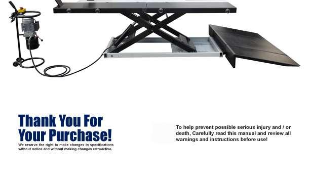
2 1.0 Introduction INSTALLATION manual Thank you for purchasing the PRO lift! This machine has been constructed using some of the highest manufacturing standards of today. This manual has been made in order to supply the owner as well as the user with basic instructions for the correct installation and use of this lift. Users of this equipment are responsible to ensure that this lift is installed and operated using the guidelines set forth in this manual. Failure to comply may result in voiding of this equipment s warranty. Read this guide thoroughly before installing or using the machine. This guide contains the instructions for installation, use and maintenance of the PRO 2500E & 1750 Heavy Duty Lifts. The PRO 2500E & PRO 1750 lifts are available with electric/hydraulic or air/hydraulic power units (customer choice). This lift was designed for the sole purpose of performing service, repairing and inspection on small equipment such as Motorcycles, ATVs, UTVs, Riding Mowers, Commercial Mowers, Trikes, etc. Any other use not described is to be considered as improper use, and thus it will be under the whole responsibility of the owner/operator and not covered under any warranties or damage that may occur. Follow the instructions in this guide carefully to ensure proper function, efficiency and a long operational life. Keep this guide available and store it with the lift. The technical literature is an integral part of the machine and it must always stay with the product, even in case of sale. Follow the directions given by this guide with the utmost attention: the seller is not responsible for any damage due to negligence and non-observance of the herewith-contained instructions. The non-observance of herewith-contained instructions will automatically involve the immediate lapse of warranty. 1.1 Intended Use This lift must only be used in the manner for which it is expressly designed. Any other use of this equipment not described in this manual is dangerous and should be avoided. The seller cannot be held responsible for any damage or injury caused by the improper use or by the nonobservance of the instructions within this manual: The lift must be installed using the specifications in this manual. The owner and all operators must be familiar with all of the operational guidelines laid out within this manual. The technical literature is an integral part of the machine. Read this guide carefully before installing or operating this machine; important safety rules for installation, operation and maintenance are enclosed. KEEP THIS AS WELL AS ALL OTHER TECHNICAL LITERATURE IN A SAFE PLACE AND CONSULT WHENEVER NECESSARY!
3


4 2.0 General Safety INSTALLATION manual 2.1 Level of Danger Whenever you find the following warning sign in this guide, pay the utmost attention and follow the relevant safety rules. ATTENTION: Read the following directions with the utmost attention. Non-observance of described procedures/practices can cause serious damages to bystanders. 2.2 HAZARDS / WARNINGS IN THE EVENT THE RAISED EQUIPMENT FALLS FROM THE LIFT, RUN AWAY TO A SAFE DISTANCE. DO NOT OPERATE A LIFT WITH PEOPLE ON IT. DO NOT STAND UNDER EQUIPMENT ON THE LIFT WHILE LIFT IS OPERATING. DEATH OR SERIOUS INJURY MAY OCCUR. IF AROUND ELECTRICAL COMPONENTS, ELECTRICAL SHOCK MAY OCCUR. DO NOT LIFT ONE SIDE OF THE EQUIPMENT. POSSIBILITY OF EQUIPMENT OVERTURN AND/OR DAMAGE TO LIFT MAY HAPPEN. AUTHORIZED PERSONNEL ONLY IN LIFT AREA. DO NOT PLACE ANY POLES UNDER EQUIPMENT AND LOWER IT TO DISMANTLE THE PART FROM THE RAISED EQUIPMENT. DO NOT SPRAY WATER DIRECTLY ONTO LIFT. DO NOT MODIFY ANY SAFETY SYSTEMS OF THIS LIFT. IF SAFETY DEVICE MALFUNCTIONS, SERIOUS ACCIDENT MAY OCCUR. DO NOT EXCESSIVELY SHAKE RAISED EQUIPMENT. DANGER OF EQUIPMENT FALLING FROM LIFT MAY OCCUR. STOP RAISING LIFT WHEN IMBALANCE IS DETECTED WHILE RASING EQUIPMENT DO NOT OPERATE LIFT WHEN HYDRAULIC OIL LEAK IS DETECTED IN THE LIFT AREA DO NOT PLACE FEET, HANDS OR ANY PART OF BODY UNDER ANY MOVING PART OF LIFT WHILE RAISING OR LOWERING.


5 2.0 General Safety INSTALLATION manual 2.3 Safety Instructions The messages and pictures shown are generic in nature and are meant to generally represent hazards common to all automotive lifts regardless of specific style. READ OPERATING AND SAFETY MANUALS BEFORE USING LIFT! DO NOT OPERATE A DAMAGED LIFT! PROPER MAINTENANCE AND INSPECTION ARE NECESSARY FOR SAFE OPERATION DAILY!? LIFT TO BE USED BY TRAINED OPERATOR ONLY!
6 3.0 Safety Warnings INSTALLATION manual CAREFULLY READ ALL INSTRUCTIONS BEFORE ATTEMPTING TO INSTALL OR OPERATE THIS LIFT! Failure to follow all instructions listed in the following pages may result in electric shock, fire, and / or serious injury. 1. Keep work area clean and well lit. Cluttered, wet, and dark work areas invites accidents. 2. Keep bystanders, children, and visitors away while operating this lift. Distractions can cause you to lose control of the equipment. 3. Stay alert, watch what you are doing,and use common sense when operating this lift. DO NOT use this lift while fatigued or under the influence of drugs, alcohol, or medication. A moment of inattention while operating this lift may result in serious personal injury. 4. RISK OF ENTANGLEMENT! Dress properly. DO NOT wear loose clothing or jewelry. Contain long hair. Keep your hair, clothing, and gloves away from moving parts. Loose clothes, jewelry, or long hair can be caught in moving parts. 5. Use safety equipment. Always wear OSHA approved safety impact eye goggles underneath a full face shield. 6. Only trained and authorized personnel should position equipment for lifting and operate this lift. 7. Use clamps (not included) or other practical ways to secure and support the work piece to a stable platform. Holding the work by hand or against your body is unstable and may lead to loss of control. Always use Tie Down Eyelets provided for securing equipment. 8. Check for misalignment or binding of moving parts, breakage of parts, and any other condition that may affect the equipment s operation. If damaged, have the equipment serviced before using. Many accidents are caused by poorly maintained equipment. 9. Use only accessories that are recommended by the manufacturer for your model. Accessories that may be suitable for one lift may become hazardous when used on another lift. 10. Service must be performed only by authorized qualified repair personnel. Service or maintenance performed by unqualified personnel could result in a risk of injury. 11. When servicing, use only identical replacement parts. Follow instructions in the INSPECTION, MAINTENANCE, AND CLEANING section of this manual. Use of unauthorized parts or failure to follow maintenance instructions may create a risk of electric shock or injury. 12. DANGER! Make sure you know the weight of the equipment you are going to lift before using the Lift. Do not exceed the maximum lift capacity (2,500 pounds and 1750 lbs.) for the Lift. Overloading the Lift could cause personal injury and / or property damage. Be aware of dynamic loading! If a weight suddenly falls onto the Lift. It may create for a brief instant an excess load which may result in personal injury and / or damage to the equipment and Lift. This Lift should be loaded only in the center of the Lift itself, from front to rear and in line with the clamping vise. 13. Use the Lift only in well ventilated areas. Carbon monoxide exhausted from running equipment engines is a colorless, odorless fume that, if inhaled, can cause serious personal injury. 14. Make sure to read and understand all instructions and safety precautions as outlined in the manufacturer s manual for the equipment you are lifting. Always use the manufacturer s recommended lifting points. 15. DO NOT use the Lift on any asphalt surface. Make sure the Lift used on a dry, oil/grease free, flat, level, concrete surface capable of supporting the weight of the Lift. DO NOT use the Lift on concrete expansion seams or on cracked, defective concrete. 16. Always examine the Lift for structural cracks, bends, damage to the hoses, and any other condition that may affect the safe operation of the Lift. DO NOT use the Lift even if minor damage is detected. 17. Prior to beginning a job, make sure the Safety Lock Assembly and its Safety Catches are in the proper position. Never work underneath equipment without using additional safety support devices such as tri-pod stands to support the Lift. 18. Always keep hands, fingers, and feet away from the moving parts of the Lift when applying or releasing a load. Remain clear of the Lift when raising or lowering equipment. 19. Use extreme caution when applying or releasing a load. Never allow the load to suddenly release. Slowly and carefully apply and release the load the Air Foot Pedal. 20. Never leave the Lift unattended when the Lift is loaded. 21. Never drive equipment onto or off of the Lift make sure the Lift is fully lowered. Never lift equipment with anyone inside it. DO NOT allow others in the lift area while operation the Lift. DO NOT allow anyone to ride on the Lift while it is being raised or lowered. DO NOT ride any equipment on the lift, they should be pushed onto the lift without a passenger. 22. DO NOT use the Lift as a permanent stand for equipment. Use the Lift only while making repairs. Then, immediately remove the equipment from the Lift. 23. Before lowering the Lift, make sure tool trays, stands, and all other tools and equipment are removed from under the equipment and the Lift. 24. DO NOT allow tearing the warning labels or other labels off the lift.

7 3.0 Safety Warnings INSTALLATION manual The warnings, precautions, and instructions discussed in this manual cannot cover all possible conditions and situations that may occur. The operator must understand that common sense and caution are factors which cannot be built into this product, but must be supplied by the operator. ONLY AFTER CAREFULLY READING ALL OF THE PRECEDING SAFETY WARNINGS SHOULD YOU ATTEMPT TO INSTALL OR OPERATE THIS LIFT! Improper installation or operation can cause injury or damage! 1. Read this installation and operation manual in its entirety before attempting to install the lift. Manufacturer or Distributor assumes no responsibility for loss or damage of any kind, expressed or implied, resulting from improper installation or use of this lift. Always use an authorized professional installer. 2. All persons using this equipment must be responsible, qualified, and carefully follow the operation and safety guidelines contained in this manual. 3. A level floor is required for proper lift installation and operation. 4. DO NOT install this lift on any asphalt surface, only on concrete surface. 5. DO NOT install this lift over concrete expansion joints or cracks. (Check with your building architect.) 6. DO NOT install this lift on an upper floor without written authorization from your building architect. Should only be installed on a basement floor. 7. DO NOT attempt to lift only part of the equipment. This lift is intended to raise the entire body of the equipment only. 8. NEVER lift any persons or equipment containing persons. This lift is designed to lift empty equipment only.
8 4.0 Installation INSTALLATION manual 4.0 READ THIS BEFORE INSTALLING THE LIFT Improper installation can cause injury or damage! 1. Read this installation and operation manual in its entirety before attempting to install the lift. Manufacturer or Distributor assumes no responsibility for loss or damage of any kind, expressed or implied, resulting from improper installation or use of this lift. Always use a authorized professional installer. 2. All persons using this equipment must be responsible, qualified, and carefully follow the operation and safety guidelines contained in this manual. 3. A level floor is required for proper lift installation and operation. 4. DO NOT attempt to lift only part of a vehicle. This lift is intended to raise the entire vehicle only. This will bend the table/cause damage and void the warranty. 5. NEVER lift any persons or equipment containing persons. This lift is designed to lift empty equipment only. 4.1 TOOLS FOR INSTALLATION Rubber Hammer Sockets and Open End Wrenches Ratchet Driver Vice Grips
9 4.0 Installation INSTALLATION manual 4.2 ASSEMBLY INSTRUCTIONS NOTE: For additional references to the parts listed in the following pages, refer to the Assembly Diagrams. 4.3 Determine the Proper Lift Location: 1. DO NOT use the Lift on any asphalt surface. Make sure the Lift is used on a dry, oil/grease free, flat, level, concrete surface capable of supporting the weight of the Lift and the equipment. Do not use the Lift on concrete expansion seams or on cracked, defective concrete. 2. Make sure to check the desired location for possible obstructions such as a low ceiling, overhead lines, adequate working area, access ways, exits, etc. 4.4 Unpacking & Setup 1. Open the shipping container, then remove the Ramp and shipping boards out of the packaging. 2. A CAREFULLY TURN TABLE UPRIGHT ONTO ITS OPERATING POSITION BEFORE REMOVING THE SHIPPING WIRE THE CABLE RESTRAINT FROM SCISSOR MECHANISM. 3. A MAKE SURE THAT THE ROLLER GUIDES CONNECTED TO THE CYLINDER ROD ARE ON THEIR TRACKS CORRECTLY BEFORE RAISING THE LIFT! 4. Connect the hose to the fitting at the hydraulic pump and bed plate. The lift may be damaged and/or personal injury may result if the hydraulic pressure exceeds the maximum psi rating. 5. Stand clear of lift table, and depress the UP side of the foot valve to raise the Table, or press the electric switch on the electric power unit to raise the Table. 6. Place Dropout Cover over Dropout opening. 7. Place ramp at end of lift table.
10 5.0 Operating Instructions INSTALLATION manual ONLY AFTER CAREFULLY READING ALL OF THE PRECEDING SAFETY WARNINGS SHOULD YOU ATTEMPT TO INSTALL OR OPERATE THIS LIFT! Improper installation or operation can cause injury or damage! 5.1 Before First Use 1. Leave the pump for one hour to allow the oil to settle before purging the system. A 2. FAILURE TO ALLOW SUFFICIENT TIME FOR THE OIL TO SETTLE COULD RESULT IN AIR REMAINING IN THE OIL. IN THIS EVENT, THE PUMP WILL NOT PURGE COMPLETELY FIRST TIME AND A SECOND PURGE WILL BE REQUIRED. 3. Test the lift, empty: move the safety pull-rod to the bayonet, raise the lift to full height, hold unloading valve (Black rounded head the handle on hydraulic pump) slowly to control the rate of descent. If air unit, use foot pedal. WARNING! Do not attempt to overload the lift. WARNING! The motorcycle must be fully supported by the deck plate before lifting. DO NOT put the rear wheel of the motorcycle on the main ramp and DO NOT use the main ramp to support the weight of the motorcycle when lifting. WARNING! The main ramp is only used to help you to wheel the motorcycle onto the platform when the lift is at its lowest position. 5.2 To Position, Lift, And Lower Equipment On The Lift: 1. Before pushing equipment onto the Lift, make sure that the Lift is fully lowered, and the approach ramps are attached and resting on the floor. Also, for two-wheel equipment, ensure that the Front Wheel Vise is opened up enough to fit the equipment s front wheel. Loads must be centered on the table at all times. The center of the table is rated for a maximum load of 2,500 lbs. on the PRO 2500 or 1,750 lbs. on the PRO Push the equipment over the Lift while keeping the equipment parallel with the Lift and aligning the center of gravity of the equipment with the center of the Lift. For motorcycles and other two wheel vehicles/equipment, push forward until the front wheel goes between the clamps on the Front Wheel Vise. DO NOT DRIVE EQUIPMENT ON OR OFF OF THE LIFT! PERSONAL INJURY MAY OCCUR WHILE STEPPING DOWN FROM THE EQUIPMENT, AND CAN ALSO CAUSE SERIOUS DAMAGE TO THE LIFT! PUSH EQUIPMENT ONTO THE LIFT WITHOUT PASSENGERS! AGAIN, NEVER DRIVE EQUIPMENT ONTO YOUR LIFT! 3. Engage the parking brake of the equipment, if applicable. 4. Once the equipment is parked, secure the equipment to the lift by tightening the Front Wheel Vise (WARNING: Make sure to only tighten the Front Wheel Vise enough to create a snug grip on the wheel. Do NOT overtighten the clamp as this can possibly damage your wheel.)
11 5.0 Operating Instructions INSTALLATION manual 5. Before Lifting: Always tie down the equipment using straps through the tie down eyelets mounted on the lift s table surface. DO THIS EVERY TIME BEFORE OPERATING LIFT! 6. Connect the hose nipple element to the electric hydraulic pump and bed plate. 7. When the platform has been raised to the working height, press the emergency switch (red mushroom button 64), or if air control, the foot pedal. NOTE: Make sure safety rod is disengaged from its stop to allow the safety plate to engage with locking mechanism at base of lift to prevent accidental lowering. 8. When work is done, remove all tools from under the lift before lowering. Raise the lift by using the electric hydraulic pump or the air hydraulic pump. Let the safety board free from its locking position, then move safety pull-rod to its locked position, SLOWLY hold unloading valve on the electric hydraulic unit (or if air control unit, use foot pedal) to GENTLY lower the lift. NOTE: Lower the motorcycle slowly, in a controlled fashion. Never allow the motorcycle to drop quickly. 9. When the lift is fully lowered, untie the vehicle, and remove it from the lift. 10. You can now release the trap or the Front Wheel Vise, and push it off of the lift. ONCE AGAIN, DO NOT DRIVE EQUIPMENT ON OR OFF OF THE LIFT!
12 6.0 Maintenance INSTALLATION 6.0 Maintenance Schedule The following periodic maintenance is the suggested minimum requirements and minimum intervals; accumulated hours or monthly period, which ever comes sooner. If you hear a noise or see any indication of possible failure - cease operation immediately and inspect, correct and/ or replace parts as required. Following these maintenance procedures is the key to prolonging the useful life of your lift. We highly recommend using a Authorized Technician for all repairs and modifications. IF AT ANY TIME YOU RE NOT SURE OF THE SAFE OPERATION OF THE LIFT, DISCONTINUE USING IT AND CALL YOUR DISTRIBUTOR FOR ASSISTANCE. Warning OSHA and ANSI require authorized users to inspect lifting equipment at the start of every shift. These and other daily periodic inspections are the responsibility of the user. 6.1 Daily Pre-Operation Check The user should at least perform the following checks daily. Daily check of Safety Locking/Latch System is very important - this could save you from expensive property damage, lost production time, serious personal injury and even death. Check to insure safety latches for free movement and full engagement are working properly. Check connections and hoses for leakage. Check the Cylinder Rod - if it becomes dry, lightly oil it. Check all bolts, nuts, and screws and tighten. Keep lift free of dirt, grease or any other corrosive substances.
13 6.0 Maintenance 6.2 Weekly Maintenance.INSTALLATION manual Check air hoses and fittings for leaks and make sure connections are tightened. Check and tighten bolts, nuts, and all screws. Pivot Shaft set screws should always be checked to insure that they are tight. Check the Cylinder Rod, if it becomes dry, lightly oil it. Lubricate the grease zerks located at either end of the Pivot Shaft. Lubricate the grease zerks at the top end of the inside frame assembly. 6.3 Six Month Annual Maintenance Lubricate the grease zerks located at either end of the Pivot Shaft. Lubricate the grease zerks at the top end of the inside frame assembly. 6.4 The following repairs should only be performed by a authorized trained maintenance expert: Replacement of shafts / axles. Replacement of roll bearings. Replacement or rebuilding hydraulic cylinders. Checking hydraulic cylinder rods and rod ends (threads) for deformation or damage. Checking cylinder mounting to make sure its not loose and /or damaged. PRO2500E and PRO 1750

14 7.0 Parts Diagrams INSTALLATION manual 7.1 Parts Breakdown NO DESCRIPION QTY NO DESCRIPION QTY NO DESCRIPION QTY 1 Baffle plate 2 37 Pin 2 53 Extension ramp Side extension Safety board base 4 54 Nut 4 3 Bolt Wheel 2 55 Screw 4 4 Washer Rod 1 56 Extension ramp Nut Pin 2 57 High pressure hose element 1 6 Tire grab 1 42 Circlip 4 58 Hydraulic cylinder hose nipple element 1 7 Pipe plug 8 43 Pin 1 59 Pump bed-frame 1 8 Lifting ring 8 44 Hydraulic cylinder hose nipple 2 60 Circlip 2 9 Quick pin 8 45 Hydraulic cylinder 1 61 Wheel 2 10 Support pipe 4 46 Pin 2 62 Lock washer 2 11 Side extension Washer 2 63 Screw 4 12 Deck plate 1 48 Rod cap 4 64 Handle cap 1 13 Lifting ring 1 49 Safety pull hile cabinet switch 1 14 Pin 1 50 Bed plate 1 66 Switch(normally open green) 1 15 Pin 2 51 Screw 2 67 Emergency switch (red mushroom button) 1 16 Washer 2 52 Main ramp 1 68 Electric hydraulic pump 1 17 Bolt 2 53 Extension ramp Tire stop 1 18 Spacing disc 4 54 Nut 4
15 7.0 Parts Diagrams INSTALLATION manual 7.2 Cylinder Parts Breakdown NO DESCRIPION QTY NO DESCRIPION QTY NO DESCRIPION QTY R01 Dust ring 1 R08 PTFE ring 1 R15 adapter 2 1 R02 Top cap 1 R09 Sealing ring 1 R16 Nut 1 R03 Bearing 1 R10 Nut 1 R17 Hydraulic cylinder hose nipple element 1 R04 Circlip 1 R11 Hydraulic cylinder element 1 R18 O-ring 1 R05 Piston rod 1 R12 Gasket 2 R19 Dust cap 1 R06 O-ring 1 R13 Ball 1 R20 Valve plates 1 R07 Ram head 1 R14 adapter 1 R21 Strainer 1 o INSTALLATION manual
16
INSTALLATION MANUAL & OPERATION INSTRUCTIONS
 INSTALLATION MANUAL & OPERATION INSTRUCTIONS INSTALLATION MANUAL Heavy-Duty ATV, UTV, Motorcycle, Trike and Commercial Lift 2500LB. UTV-2500-60 (60 x 94-1/2 Lift Table) UTV-2500-64 (64 x 94-1/2 Lift Table)
Installation Manual & Operation Instructions
 & Operation Instructions Motorcycle Lift PSE TCML / PSE TCMLW PSE TCML (24 x 110 Lift Table) PSE TCMLW (48 x 110 Lift Table) Heavy-Duty Motorcycle Lift w/ Service Jack 1,500 LB. Capacity Lift Features:
INSTALLATION MANUAL & OPERATION INSTRUCTIONS
 INSTALLATION MANUAL & OPERATION INSTRUCTIONS MOTORCYCLE LIFT TCML / TCMLW INSTALLATION Manual TCML TCMLW LIFT FEATURES: (24 x 110 Lift Table) (48 x 110 Lift Table) Heavy-Duty Motorcycle Lift w/ Service
AIR/OVER HYDRAULIC JACK 20 TON
 AIR/OVER HYDRAULIC JACK 0 TON 4487 ASSEMBLY AND OPERATING INSTRUCTIONS 349 Mission Oaks Blvd., Camarillo, CA 930 Visit our Web site at http://www.harborfreight.com Copyright 999 by Harbor Freight Tools.
INTENDED USE TECHNICAL SPECIFICATIONS
 1/2IN. HEAVY-DUTY AIR IMPACT WRENCH OWNER S MANUAL WARNING: Read carefully and understand all INSTRUCTIONS before operating. Failure to follow the safety rules and other basic safety precautions may result
60 farm jack. Distributed exclusively by Harbor Freight Tools Mission Oaks Blvd., Camarillo, CA 93011
 60 farm jack 66183 Set up And Operating Instructions Distributed exclusively by Harbor Freight Tools. 3491 Mission Oaks Blvd., Camarillo, CA 93011 Visit our website at: http://www.harborfreight.com Read
2000 lb manual winch
 2000 lb manual winch Model 41694 Operation Instructions Due to continuing improvements, actual product may differ slightly from the product described herein. 3491 Mission Oaks Blvd., Camarillo, CA 93011
OWNER S MANUAL. Page: 1 of 8
 Air Needle Scaler OWNER S MANUAL WARNING: Read carefully and understand all INSTRUCTIONS before operating. Failure to follow the safety rules and other basic safety precautions may result in serious personal
60 Drum Style Spike Aerator
 60 Drum Style Spike Aerator OWNER S MANUAL WARNING: Read carefully and understand all ASSEMBLY AND OPERATION INSTRUCTIONS before operating. Failure to follow the safety rules and other basic safety precautions
G10K - 1/2" Heavy-Duty Air Impact Wrench
 G10K - 1/2" Heavy-Duty Air Impact Wrench OWNER S MANUAL WARNING: Read carefully and understand all ASSEMBLY AND OPERATION INSTRUCTIONS before operating. Failure to follow the safety rules and other basic
Composite Pistol-Type Air Needle Scaler OWNER S MANUAL
 Composite Pistol-Type Air Needle Scaler OWNER S MANUAL WARNING: Read carefully and understand all INSTRUCTIONS before operating. Failure to follow the safety rules and other basic safety precautions may
1000-Lb. Rapid Lift Hydraulic Table
 1000-Lb. Rapid Lift Hydraulic Table Owner s Manual WARNING: Read carefully and understand all ASSEMBLY AND OPERATION INSTRUCTIONS before operating. Failure to follow the safety rules and other basic safety
Operating Instructions and Parts Manual 24529
 Please read and save these instructions. Read through this owner s manual carefully before using product. Protect yourself and others by observing all safety information, warnings, and cautions. Failure
3/8" Dr. Air Butterfly Impact Wrench
 8192106 3/8" Dr. Air Butterfly Impact Wrench Owner s Manual Read and understand all instructions before use. Retain this manual for future reference. Specifications Construction: Polished aluminum and
HEAVY-DUTY AIR RATCHET WRENCH OWNER S MANUAL
 HEAVY-DUTY AIR RATCHET WRENCH OWNER S MANUAL WARNING: Read carefully and understand all INSTRUCTIONS before operating. Failure to follow the safety rules and other basic safety precautions may result in
20 Ton SD Shop Press Operating Instructions
 20 Ton SD Shop Press Operating Instructions MODEL NO. 850SD Hazard Symbols Used in the Manuals This manual includes the hazard symbols defined below when the operations or maintenance job involves a potential
WALL-MOUNT GARDEN HOSE REEL OWNER S MANUAL
 WALL-MOUNT GARDEN HOSE REEL OWNER S MANUAL Perpendicular Mount Parallel Mount WARNING: Read carefully and understand all ASSEMBLY AND OPERATION INSTRUCTIONS before operating. Failure to follow the safety
75 Ton SD Shop Press Operating Instructions
 75 Ton SD Shop Press Operating Instructions MODEL NO. 856SD Hazard Symbols Used in the Manuals This manual includes the hazard symbols defined below when the operations or maintenance job involves a potential
AIR OVER HYDRAULIC ATV/MOTORCYCLE LIFT SET UP AND OPERATING INSTRUCTIONS
 AIR OVER HYDRAULIC ATV/MOTORCYCLE LIFT SET UP AND OPERATING INSTRUCTIONS Read this material before using this product. Failure to do so can result in serious injury. SAVE THIS MANUAL. SAVE THIS MANUAL
AIR INLINE METAL SHEAR
 AIR INLINE METAL SHEAR ASSEMBLY and OPERATING INSTRUCTIONS 3491 Mission Oaks Blvd. / Camarillo, CA 93011 Copyright 1997 by Harbor Freight Tools. All rights reserved. No portion of this manual or any artwork
300 Lbs. Motorcycle Scissor Lift
 300 Lbs. Motorcycle Scissor Lift 65318 Set up and Operating Instructions Distributed exclusively by Harbor Freight Tools. 3491 Mission Oaks Blvd., Camarillo, CA 93011 Visit our website at: http://www.harborfreight.com
Instruction Manual LIMITED 1 YEAR WARRANTY. Hydraulic Punch Driver Read this material before using this product.
 Instruction Manual Hydraulic Punch Driver 902-483 LIMITED 1 YEAR WARRANTY We make every effort to assure that its products meet high quality and durability standards, and warrant to the original purchaser
8 TON AIR/MANUAL FLAT BOTTOM JACK
 8 TON AIR/MANUAL FLAT BOTTOM JACK Model 95967 OPERATION INSTRUCTIONS Due to continuing improvements, actual product may differ slightly from the product described herein. 3491 Mission Oaks Blvd., Camarillo,
 TABLE OF CONTENTS... 2... 2... 3... 5... 6... 7... 7... 15... 16... 17... 17... 19... 20... 21 IMPORTANT INFORMATION Two Post Lifts 1. 2. - There can be no cracks in the slab within 36 in. of the base
HYDRAULIC MOBILE LIFTING TABLE
 HYDRAULIC MOBILE LIFTING TABLE MODEL NO: HTL300 & HTL500 PART NO: 7610148 & 76210152 OPERATION & MAINTENANCE INSTRUCTIONS ORIGINAL INSTRUCTIONS GC1116 INTRODUCTION Thank you for purchasing this CLARKE
1 DRIVE INDUSTRIAL IMPACT WRENCH
 1 DRIVE INDUSTRIAL IMPACT WRENCH 92622 ASSEMBLY AND OPERATING INSTRUCTIONS 3491 Mission Oaks Blvd., Camarillo, CA 93011 Visit our Web site at http://www.harborfreight.com Copyright 2004 by Harbor Freight
Copyright MAY, 2008 By Grizzly Industrial, Inc. Warning: No portion of this manual may be reproduced in any shape or form without the written
 MODEL G5789/G5790 13-PIECE 3 4" IMPACT WRENCH KIT INSTRUCTION MANUAL Copyright MAY, 2008 By Grizzly Industrial, Inc. Warning: No portion of this manual may be reproduced in any shape or form without the
COMPACT METAL bender 99826
 COMPACT METAL bender 99826 Set up And Operating Instructions Distributed exclusively by Harbor Freight Tools. 3491 Mission Oaks Blvd., Camarillo, CA 93011 Visit our website at: http://www.harborfreight.com
Copyright MAY, 2008 By Grizzly Industrial, Inc. Warning: No portion of this manual may be reproduced in any shape or form without the written
 MODEL G5791/G5792 17-PIECE 1 2" IMPACT WRENCH & RATCHET KIT INSTRUCTION MANUAL Copyright MAY, 2008 By Grizzly Industrial, Inc. Warning: No portion of this manual may be reproduced in any shape or form
accidents which arise due to non-observance of these instructions and the safety information herein. SPECIFICATIONS
 18 GAUGE 1-1/4 INCH BRAD NAILER Model: 7611 CALIFORNIA PROPOSITION 65 WARNING: You can create dust when you cut, sand, drill or grind materials such as wood, paint, metal, concrete, cement, or other masonry.
LUBRICATOR ASSEMBLY AND OPERATING INSTRUCTIONS
 AIR FILTER, REGULATOR AND LUBRICATOR 4035 ASSEMBLY AND OPERATING INSTRUCTIONS 349 Mission Oaks Blvd., Camarillo, CA 930 Visit our Web site at http://www.harborfreight.com Copyright 004 by Harbor Freight
Model Visit our website at:
 6 DIAL Fractional CALIPER Model 92437 Set up And Operating Instructions Visit our website at: http://www.harborfreight.com Read this material before using this product. Failure to do so can result in serious
HIGH WHEEL HOSE REEL CART OWNER S MANUAL
 HIGH WHEEL HOSE REEL CART OWNER S MANUAL WARNING: Read carefully and understand all ASSEMBLY AND OPERATION INSTRUCTIONS before operating. Failure to follow the safety rules and other basic safety precautions
TRI- B A L L H I TC H OWNER S MANUAL
 TRI- B A L L H I TC H OWNER S MANUAL WARNING: Read carefully and understand all INSTRUCTIONS before operating. Failure to follow the safety rules and other basic safety precautions may result in serious
6 DUAL ACTION AIR SANDER
 6 DUAL ACTION AIR SANDER Model 42966 ASSEMBLY AND OPERATING INSTRUCTIONS 3491 Mission Oaks Blvd., Camarillo, CA 93011 Visit our Web site at http://www.harborfreight.com TO PREVENT SERIOUS INJURY, READ
accidents which arise due to non-observance of these instructions and the safety information herein. SPECIFICATIONS
 18 GAUGE 2 INCH BRAD NAILER Model: 7555 CALIFORNIA PROPOSITION 65 WARNING: You can create dust when you cut, sand, drill or grind materials such as wood, paint, metal, concrete, cement, or other masonry.
Angled Sign Light with Shade
 Angled Sign Light with Shade Owner s Manual WARNING: Read carefully and understand all ASSEMBLY AND OPERATION INSTRUCTIONS before operating. Failure to follow the safety rules and other basic safety precautions
4-in-1 Professional Inflator Kit
 4-in-1 Professional Inflator Kit Owner s Manual WARNING: Read carefully and understand all ASSEMBLY AND OPERATION INSTRUCTIONS before operating. Failure to follow the safety rules and other basic safety
NOTE: Parts are no longer available for this tool. The manual will continue on the next page.
 NOTE: Parts are no longer available for this tool. The manual will continue on the next page. Form Z455 Date 12-97/D Page 1 of 6 INSTRUCTIONS & PARTS LIST FOR SIOUX 8200 POLISHER GENERAL SAFTEY RULES READ
Owner s Manual & Safety Instructions
 Owner s Manual & Safety Instructions Save This Manual Keep this manual for the safety warnings and precautions, assembly, operating, inspection, maintenance and cleaning procedures. Write the product s
TEM# Air Hammer Combo USER'S MANUAL
 Air Tools TEM# 40 Air Hammer Combo USER'S MANUAL Read carefully and understand RULES FOR SAFE OPERATION and instructions before operating. Failure to follow the safety rules and other basic safety precautions
Heavy Duty Drag Harrow
 Heavy Duty Drag Harrow OWNER S MANUAL WARNING: Read carefully and understand all ASSEMBLY AND OPERATION INSTRUCTIONS before operating. Failure to follow the safety rules and other basic safety precautions
SPECIFICATIONS TABLE Maximum Air Pressure 115 PSI Air Tank Capacity 20 Gallons
 SPECIFICATIONS TABLE Maximum Air Pressure 115 PSI Air Tank Capacity 20 Gallons Air Flow Capacity 6.2 CFM at 40 PSI 5.2 CFM at 90 PSI Motor 2.5 HP Working / 4 HP Peak 120 Volt / 60 Hz / 13 A / 1-Phase Required
Owner s Manual & Safety Instructions
 Owner s Manual & Safety Instructions Save This Manual Keep this manual for the safety warnings and precautions, assembly, operating, inspection, maintenance and cleaning procedures. Write the product s
1/4 Air Ratchet Wrench
 /4 Air Ratchet Wrench 92849 ASSEMBLY AND OPERATING INSTRUCTIONS 349 Mission Oaks Blvd., Camarillo, CA 930 Visit our Web site at http://www.harborfreight.com Copyright 2005 by Harbor Freight Tools. All
30T A/Manual Hydraulic Shop Press
 30T A/Manual Hydraulic Shop Press Operation Manual 1 1. Important Information 1.1 Safety Information 1.1.1 Hazard Symbols Used in the Manuals This manual includes the hazard symbols defined below when
Heavy Duty Drag Harrow
 Heavy Duty Drag Harrow OWNER S MANUAL WARNING: Read carefully and understand all ASSEMBLY AND OPERATION INSTRUCTIONS before operating. Failure to follow the safety rules and other basic safety precautions
AIR HYDRAULIC RIVETER
 AIR HYDRAULIC RIVETER Owner s Manual WARNING: Read carefully and understand all ASSEMBLY AND OPERATION INSTRUCTIONS before operating. Failure to follow the safety rules and other basic safety precautions
Owner s. product. Failure injury
 100-Ft. Hose Reel Cart Owner s Manual WARNING: Read and understand all instructions, warnings, and cautions before using this product. Failure to follow the instructions, warnings, and cautions may result
IMPACT WRENCH ASSEMBLY AND OPERATING INSTRUCTIONS
 1 / 2 COMPACT AIR TWIN HAMMER IMPACT WRENCH 94802 ASSEMBLY AND OPERATING INSTRUCTIONS Due to continuing improvements, actual product may differ slightly from the product described herein. 3491 Mission
MODEL H8214 AIR BODY SAW INSTRUCTION MANUAL
 MODEL H8214 AIR BODY SAW INSTRUCTION MANUAL COPYRIGHT SEPTEMBER, 2007 BY GRIZZLY INDUSTRIAL, INC. WARNING: NO PORTION OF THIS MANUAL MAY BE REPRODUCED IN ANY SHAPE OR FORM WITHOUT THE WRITTEN APPROVAL
310 SERIES TILT-TO-LOAD ROTATOR. The Specialist In Drum Handling Equipment
 OPERATOR S MANUAL FOR MORSE TILT-TO-LOAD DRUM ROTATOR SAFETY INFORMATION: While Morse Manufacturing Co. drum handling equipment is engineered for safety and efficiency, a high degree of responsibility
Air over Hydraulic. Model 98178
 Air over Hydraulic ATV/Motorcycle Lift Model 98178 Set up and Operating Instructions Distributed exclusively by Harbor Freight Tools. 3491 Mission Oaks Blvd., Camarillo, CA 93011 Visit our website at:
ORBITAL AIR SANDER. Owner s Manual
 ORBITAL AIR SANDER Owner s Manual WARNING: Read carefully and understand all ASSEMBLY AND OPERATION INSTRUCTIONS before operating. Failure to follow the safety rules and other basic safety precautions
3:1 High Ratio Oil Pump W. Extn. Kit
 3:1 High Ratio Oil Pump W. Extn. Kit OWNER S MANUAL WARNING: Read carefully and understand all INSTRUCTIONS before operating. Failure to follow the safety rules and other basic safety precautions may result
12 Inch Barn Light. Owner s Manual
 12 Inch Barn Light Owner s Manual WARNING: Read carefully and understand all ASSEMBLY AND OPERATION INSTRUCTIONS before operating. Failure to follow the safety rules and other basic safety precautions
1/4 SHEET PALM SANDER
 1/4 SHEET PALM SANDER OWNER S MANUAL WARNING: Read carefully and understand all ASSEMBLY AND OPERATION INSTRUCTIONS before operating. Failure to follow the safety rules and other basic safety precautions
OPERATING INSTRUCTIONS. Parts List N. Note: Owner and operator MUST read and understand this operating instructions before use this lift table.
 OPERATING INSTRUCTIONS Parts List 770N te: Owner and operator MUST read and understand this operating instructions before use this lift table. Thank you for using this lift table. Your lift table is made
MODEL H RPM
 MODEL H8217 3 8" REVERSIBLE ANGLE DRILL 0 1500 RPM INSTRUCTION MANUAL COPYRIGHT AUGUST, 2007 BY GRIZZLY INDUSTRIAL, INC. WARNING: NO PORTION OF THIS MANUAL MAY BE REPRODUCED IN ANY SHAPE OR FORM WITHOUT
1/2 in. AIR IMPACT WRENCH (TWIN HAMMER)
") 1/2 in. AIR IMPACT WRENCH (TWIN HAMMER) WARNING Read Operator s Manual. Do not operate equipment until you have read this Operator s Manual for Safety, Assembly/Operation and Maintenance Instructions.
1/2 in. AIR IMPACT WRENCH (TWIN HAMMER) WARNING Read Operator s Manual. Do not operate equipment until you have read this Operator s Manual for Safety, Assembly/Operation and Maintenance Instructions.
SHHP50 FLOOR STANDING HYDRAULIC PRESS
 SHHP50 FLOOR STANDING HYDRAULIC PRESS OWNER S MANUAL FOR YOUR SAFETY PLEASE READ THESE INSTRUCTIONS CAREFULLY AND RETAIN THEM FOR FUTURE USE. SPECIFICATION MAX CAPACITY STROKE WORK RANGE WEIGHT 50 TON
20 Ton Air Over Hydraulic Jack
 20 Ton Air Over Hydraulic Jack Model 95553 Assembly And Operation Instructions Diagrams within this manual may not be drawn proportionally. Due to continuing improvements, actual product may differ slightly
Instruction Manual. PE Pipe Squeeze-off Tool Model TR650
 PE Pipe Squeeze-off Tool Model TR650 Instruction Manual For your personal safety READ and UNDERSTAND instructions before using tools. SAVE these instructions for future reference. SPECIFICATIONS Table
PDY TON HYDRAULIC CRIMPING TOOL WARNING
 OPERATORS ORS GUIDE PDY-1220 12 TON HYDRAULIC CRIMPING TOOL All information found in this guide must be read and understood before use or testing of this tool. Failure to read and understand these warnings
IMPORTANT SAFETY INFORMATION
 WARNING SYMBOLS AND DEFINITIONS This is the safety alert symbol. It is used to alert you to potential personal injury hazards. Obey all safety messages that follow this symbol to avoid possible injury
foldable/adjustable sawhorse
 foldable/adjustable sawhorse Model 96506 Set up And Operating Instructions Diagrams within this manual may not be drawn proportionally. Due to continuing improvements, actual product may differ slightly
1/2 Twin Hammer Composite. Air Impact Wrench ASSEMBLY AND OPERATING INSTRUCTIONS
 1/2 Twin Hammer Composite Air Impact Wrench 95098 ASSEMBLY AND OPERATING INSTRUCTIONS Due to continuing improvements, actual product may differ slightly from the product described herein. 3491 Mission
Steel Spring Driven Reel Instruction Manual
 Steel Spring Driven Reel Instruction Manual WARNING: Read carefully and understand all INSTRUCTIONS before operating. Failure to follow the safety rules and other basic safety precautions may result in
MODEL H8253 AIR BELT SANDER INSTRUCTION MANUAL
 MODEL H8253 AIR BELT SANDER INSTRUCTION MANUAL COPYRIGHT DECEMBER, 2007 BY GRIZZLY INDUSTRIAL, INC. WARNING: NO PORTION OF THIS MANUAL MAY BE REPRODUCED IN ANY SHAPE OR FORM WITHOUT THE WRITTEN APPROVAL
35 TON HYDRAULIC PUNCH WARNING
 OPERATORS GUIDE REL-35T-PNC 35 TON HYDRAULIC PUNCH NOTICE Sizes, weights and tool specifications listed in this manual are subject to change without notice. Please consult factory for information and updates.
10 DRIP NOZZLE WATERING DRIP KIT Model / Model 46095
 10 DRIP NOZZLE WATERING DRIP KIT Model 93261 / Model ASSEMBLY AND OPERATING INSTRUCTIONS Due to continuing improvements, actual product may differ slightly from the product described herein. 3491 Mission
Model ASSEMBLY and OPERATING INSTRUCTIONS
 QUICK CHANGE AIR BRUSH KIT Model 93506 ASSEMBLY and OPERATING INSTRUCTIONS Due to continuing improvements, actual product may differ slightly from the product described herein. 3491 Mission Oaks Blvd.,
Model PSI Compressor with 3-Gallon Air Tank 12VDC
 Model 6350 150 PSI Compressor with 3-Gallon Air Tank 12VDC IMPORTANT: It is essential that you and any other operator of this product read and understandd the contents of this manual before installing
ATD LB PRESSURE BLASTER INSTRUCTION MANUAL
 ATD-8402 90LB PRESSURE BLASTER INSTRUCTION MANUAL SAVE THESE INSTRUCTIONS SAFETY INSTRUCTIONS FOR SANDBLASTER 1. Before opening the tank release the air pressure on the sand tank. To do this, turn off
3/8" Air Impact Wrench
 3/8" Air Impact Wrench Owner s Manual WARNING: Read carefully and understand all ASSEMBLY AND OPERATION INSTRUCTIONS before operating. Failure to follow the safety rules and other basic safety precautions
Heavy duty English wheel
 Heavy duty English wheel 65619 Set up and Operating Instructions Distributed exclusively by Harbor Freight Tools. 3491 Mission Oaks Blvd., Camarillo, CA 93011 Visit our website at: http://www.harborfreight.com
Hole cutter. Model 97194
 Hole cutter Model 97194 Set up And Operating Instructions Diagrams within this manual may not be drawn proportionally. Due to continuing improvements, actual product may differ slightly from the product
AIR COMPRESSOR OPERATING INSTRUCTION AND PARTS LIST
 AIR COMPRESSOR OPERATING INSTRUCTION AND PARTS LIST OIL-LESS TYPE IMPORTANT: PLEASE READ CAREFULLY BEFORE STARTING OPERATIONS. THE CONTENTS ARE FOR GENERAL INFORMATION OF ALL THE SIMILAR MODELS. Record
Retractable Hose Reel with 3/8" x 50' PVC Hose
 Retractable Hose Reel with 3/8" x 50' PVC Hose Item# 4816153 Owner s Manual Assembly and Operation Instructions MADE IN CHINA Read carefully and understand all ASSEMBLY AND OPERATION INSTRUCTIONS before
7130 Lancer Rear Drive Magnetic Commercial Indoor Cycling Bike
 7130 Lancer Rear Drive Magnetic Commercial Indoor Cycling Bike Owner s Manual Made in Taiwan INDEX IMPORTANT SAFETY INFORMATION... 1 EXPLODED DRAWING... 2 PARTS LIST... 3 ASSEMBLY INSTRUCTION... 4-9 USER
4-BIKE HITCH RACK OWNER S MANUAL
 4-BIKE HITCH RACK OWNER S MANUAL WARNING: Read carefully and understand all ASSEMBLY AND OPERATION INSTRUCTIONS before operating. Failure to follow the safety rules and other basic safety precautions may
Pressure Relief Valve Instruction Manual
 CVR3-M0_062017 Pressure Relief Valve Instruction Manual MODEL: CVR3 SFA Companies 10939 N. Pomona Ave. Kansas City, MO 64153 Tel: 888-332-6419 * Fax: 816-448-2142 E-mail: sales@bvahydraulics.com Website:
HATFIELD. Continuing the Tradition SEMI-AUTOMATIC SHOTGUN INSTRUCTION MANUAL
 HATFIELD Continuing the Tradition SEMI-AUTOMATIC SHOTGUN INSTRUCTION MANUAL READ THE INSTRUCTIONS AND WARNINGS IN THIS MANUAL CAREFULLY BEFORE USING THIS FIREARM SAFETY HANDLING RULES 1.Always keep the
1/4 COMPOSITE AIR DIE GRINDER
 1/4 COMPOSITE AIR DIE GRINDER 95029 ASSEMBLY AND OPERATING INSTRUCTIONS Due to continuing improvements, actual product may differ slightly from the product described herein. 3491 Mission Oaks Blvd., Camarillo,
AIR HAMMERS MODEL NO: CAT138/CAT139 OPERATING & MAINTENANCE INSTRUCTIONS PART NO: / GC064
 AIR HAMMERS MODEL NO: CAT138/CAT139 PART NO: 3120152 /3120153 OPERATING & MAINTENANCE INSTRUCTIONS GC064 INTRODUCTION Thank you for purchasing this CLARKE Air Hammer. Before attempting to use this product,
Reciprocating saw attachment
 Reciprocating saw attachment Model 96635 Set up And Operating Instructions Diagrams within this manual may not be drawn proportionally. Due to continuing improvements, actual product may differ slightly
1/2 in. Air Impact Wrench
 1/2 in. Air Impact Wrench Owner s Manual WARNING: Read carefully and understand all ASSEMBLY AND OPERATION INSTRUCTIONS before operating. Failure to follow the safety rules and other basic safety precautions
CUT OFF TOOL MODEL: CAT113
 CUT OFF TOOL MODEL: CAT113 Part No: 3120135 ASSEMBLY & INSTRUCTION MANUAL LS0309 INTRODUCTION Thank you for purchasing this CLARKE product Before attempting to use the product, it is essential that you
Tru Trak Sulky Proline Mid Size Mower Attachment
 Form No. -7 Tru Trak Sulky Proline Mid Size Mower Attachment Model No. 00 000000 and Up Operator s Manual Domestic English (EN) Contents Page Introduction................................ Safety.....................................
AC1810 / AC1810-A TECHNICAL SPECIFICATIONS. Operating Pressure psi ( kgs/cm²) [AC1810] Displacement. Net Weight
![AC1810 / AC1810-A TECHNICAL SPECIFICATIONS. Operating Pressure psi ( kgs/cm²) [AC1810] Displacement. Net Weight](/thumbs/83/88369739.jpg "AC1810 / AC1810-A TECHNICAL SPECIFICATIONS. Operating Pressure psi ( kgs/cm²) [AC1810] Displacement. Net Weight") Technical Specifications Operating Instructions Maintenance Information Troubleshooting Guide Parts Diagrams AC1810 / AC1810-A THE EVOLUTION OF PERFECTION CAUTION: Before attempting to use or service this
Technical Specifications Operating Instructions Maintenance Information Troubleshooting Guide Parts Diagrams AC1810 / AC1810-A THE EVOLUTION OF PERFECTION CAUTION: Before attempting to use or service this
VL 2K LIFT D-L WINCH INSTRUCTIONS (Applies to P/Ns , , , , , )
") VL 2K LIFT D-L WINCH INSTRUCTIONS (Applies to P/Ns 3714022, 3714028, 3714034, 3714040, 3714043, 3714046) REIMANN & GEORGER CORPORATION MARINE PRODUCTS BUFFALO, NY P/N 6112103 04/09/18 1 SAFETY 1.1 INTRODUCTION
VL 2K LIFT D-L WINCH INSTRUCTIONS (Applies to P/Ns 3714022, 3714028, 3714034, 3714040, 3714043, 3714046) REIMANN & GEORGER CORPORATION MARINE PRODUCTS BUFFALO, NY P/N 6112103 04/09/18 1 SAFETY 1.1 INTRODUCTION
20 TON SHOP PRESS WITH OIL FILTER CRUSHER
 20 TON SHOP PRESS WITH OIL FILTER CRUSHER 65330 Set up and Operating Instructions Distributed exclusively by Harbor Freight Tools. 3491 Mission Oaks Blvd., Camarillo, CA 93011 Visit our website at: http://www.harborfreight.com
Model # MHVSS Vertical Sausage Stuffer INSTRUCTION MANUAL
 Model # MHVSS Vertical Sausage Stuffer INSTRUCTION MANUAL READ ALL INSTRUCTIONS AND WARNINGS BEFORE USING THIS PRODUCT. This manual provides important information on proper operation & maintenance. Every
HYDRAULIC WINCH FOR AUGERS UP TO WR10 X 71 / W130 X 41 ASSEMBLY & OPERATION MANUAL
 HYDRAULIC WINCH ASSEMBLY & OPERATION MANUAL Read this manual before using product. Failure to follow instructions and safety precautions can result in serious injury, death, or property damage. Keep manual
Soot Buster. Operating and Maintenance Instructions. M
 Soot Buster M5784-00 Tube & Pipe Cleaners Tube Testers Tube Plugs Tube Removal Tube Installation Operating and Maintenance Instructions www.elliott-tool.com TABLE OF CONTENTS Introduction... 4 Safety
3 Post Pressure Fit System Owner s Manual
 3 Post Pressure Fit System Owner s Manual Use and Care Trouble Shooting Warranty Information Table of Contents 3 Post Pressure Fit System Introduction... 3 Overview of the 3 Post Pressure Fit System...
Belt Sander. Owner s Manual
 Belt Sander Owner s Manual WARNING: Read carefully and understand all ASSEMBLY AND OPERATION INSTRUCTIONS before operating. Failure to follow the safety rules and other basic safety precautions may result
REL-510H WARNING NOTICE 12 TON SINGLE ACTING REMOTE HYDRAULIC CRIMPING HEAD
 OPERATORS ORS GUIDE REL-510H 12 TON SINGLE ACTING REMOTE HYDRAULIC CRIMPING HEAD Compatible with U style and RELIABLE R12 shell type 12 ton compression dies. RELIABLE EQUIPMENT & SERVICE CO., INC. 92 Steamwhistle
4 ANGLE GRINDER MODEL NO: CAT 52 PART
 4 ANGLE GRINDER 4 ANGLE GRINDER MODEL NO: CAT 52 PART No: 3110685 OPERATION & MAINTENANCE INSTRUCTIONS 0807 Fig.1 SPECIFICATIONS Model:...CAG52 Part Number:...3110685 Rated Wheel...Capacity: 4 x 1/4 (type
MODEL 200 KNIFE GATE VALVES INSTALLATION & MAINTENANCE MANUAL
 MODEL 200 KNIFE GATE VALVES INSTALLATION & MAINTENANCE MANUAL Index 1. List of components / General arrangement 2. Description 3. Handling 4. Installation 5. Actuators / Operation 6. Maintenance a. Changing