Module 6. Tightness Testing
|
|
|
- Louise Shepherd
- 5 years ago
- Views:
Transcription
1 Module 6 Tightness Testing

2 IGE / UP / 1B New Tightness Testing Procedure Covers pipework up to 35mm and installation volumes of 0.035m3
3 Objectives By the end of Module 6, Tightness Testing and Direct Purging of Small Natural Gas Installations, you should be able to show understanding in the following areas: The correct selection and reading of pressure gauges The allowed pressure drops for existing installations related to meter size/type, pipe diameter and internal volume (IV) with appliances connected to the gas supply and not isolated including Ultrasonic E6, Diaphragm U6/G4, U16/G10 meters and where no meter is fitted The identification of no perceptible movement on the gauge (0.25mbar water gauge and 0.2mbar electronic gauge reading to one decimal place) The allowed pressure drop for an existing installation to be tested including emergency control valve but no meter is installed e.g. flat where supply is not individually metered.
4 Objectives Electronic token meter tamper devices and their effect on tightness testing The procedures for dealing with an emergency/meter control that is letting by The actions to be taken when a smell of gas persists (a) after completion of a satisfactory soundness test (b) when the ECV/AECV/MIV is turned off or a leaking installation cannot be repaired Tightness testing requirements when carrying out gas work on pipework over 35mm or where total IV exceeds 0.035m 3 Tightness testing requirements prior to alteration or extension to existing installations Acronyms and symbols used within the industry standard used for tightness testing Calculating internal volume (IV) and purge volume (PV) exercise for installations with E6, U6 G4 meters connected to 35mm pipework and U16 meters connected to any pipework up to 35mm The requirements for purging installations with an IV < 0.02m 3 and those exceeding 0.02m 3 Additional tests required where the supply MOP exceeds 75mbar, but a meter inlet valve (MIV) is not fitted.
5 Regulations and Standards The main Regulations and Standard applying to Tightness Testing and Purging of domestic sized natural gas installations are: Regulations 22 and 33 - Gas Safety (Installation and Use) Regulations 1998 IGE/UP/1B Edition 3 - Tightness testing and direct purging of small Liquefied Petroleum Gas/Air, Natural Gas and Liquefied Petroleum Gas installations.
6 When to Test for Tightness On completion of new pipework installations After alteration to, replacement of, or re-use of, existing installations New extensions to existing pipework Prior to any work (see Gas Safety (Installation and Use) Regulations (GS(I&U)R) on existing pipework Where there is a known or suspected gas leak in installations Where there has been a complete loss of pressure for any reason.
7 When to Test for Tightness Tightness testing procedures also apply to installations where: Gas appliances are not connected Gas appliances are connected but are isolated Gas appliances are connected, not isolated, but are turned off at the operating tap(s) A meter is installed and no outlet pipework is connected.
8 Direct Purging Direct purging of installations is required in the following circumstances: New installations Alteration to, replacement of, or re-use of existing installations New extensions to existing installations Where there has been a complete loss of installation pressure for any reason Where there is the possibility of air being present in an installation Where an installation is to be taken out of service temporarily or permanently.
9 The Correct Selection and Reading of Pressure Gauges Pressure Gauges To carry out a tightness test the most important piece of equipment required is some form of pressure gauge. There are many types of gauge that exist including: U gauge - also known as a water gauge or U tube manometer Electronic pressure gauges.
 fluid is not considered suitable for the purpose of tightness testing Most U gauges incorporate dual scales for reading in millibars (mbar) or")
10 The Correct Selection and Reading of Pressure Gauges U tube manometers are generally filled to the zero level using a suitable fluid of specific gravity (SG) = 1, i.e. water Any gauge which is filled to the zero level using high specific gravity (SG) fluid is not considered suitable for the purpose of tightness testing Most U gauges incorporate dual scales for reading in millibars (mbar) or inches water gauge ("WG) Only older appliances refer to working pressures in "WG, so we will use mbar for all work with pressures throughout this module Should you wish for any reason to convert millibars to "WG, simply divide by 2.5. E.g. 7.5mbar 2.5 = 3"WG

11 The Correct Selection and Reading of Pressure Gauges When reading the gauge, for accuracy, it is essential that the gauge is vertical, as tilting it will give false readings Similarly if the operative s eyes are not level with the meniscus then the reading can be misinterpreted If a reading is taken without zeroing the scale, a true reading can be obtained by reading each column separately, adding the two readings together and then dividing by 2 For example if one column reads 12mbar and the other 14mbar then the true reading would be: 13mbar, i.e. 12mbar + 14mbar = 26mbar 2 = 13mbar

12 The Correct Selection and Reading of Pressure Gauges Electronic Gauges Electronic pressure gauges are becoming increasingly popular, particularly as they can be used for taking the differential pressure readings that are required on some modern appliances They are usually capable of reading pressures to one decimal place and as a result can be misleading if an operative is not concentrating, i.e. 1.0mbar could be read as 10mbar.
13 The Correct Selection and Reading of Pressure Gauges Electronic Gauges IGE/UP/1B Edition 3 specifies tolerances for equipment used when tightness testing a gas installation. These are: Any water gauge shall be capable of being read to an accuracy of 0.5mbar or better Any electronic gauge shall be capable of being read to an accuracy of 0.1mbar. IGE/UP/1B Edition 3 also declares that any electronic gauge shall be: Operated within the manufacturer s specification for ambient temperature Be stabilised at the ambient temperature as stated by the manufacturer, prior to the test being carried out Be calibrated annually and be intrinsically safe.


14 Using the U Gauge Check that the gauge is in good condition and that the glass is clean Fill the gauge to zero position with clean water; ensure that there are no air bubbles The scale may be adjusted slightly to obtain a zero reading The gauge must be supported firmly in the vertical position by using either the stand or other method of support When using a dual scale gauge ensure the tube is connected to the correct side to make certain the required scale is used, e.g. mbar or inches water gauge Admit the gas slowly to prevent a surge in pressure which may blow the gauge water out Read the correct level and avoid errors, and ensure the reading is the same on both limbs of the gauge.
15 Criteria for Tightness Testing New installation pipework with new meter New installation pipework - no meter fitted Existing installation pipework and existing meter Existing installation pipework and new meter New extension New or existing installation with a gas meter but no outlet pipework connected.

16 Criteria for Tightness Testing

17 Criteria for Tightness Testing

18 Criteria for Tightness Testing
19 Perceptible Movement For new installations and for all let by tests, the pass criteria is no perceptible movement during the test period Note: A movement of 0.25mbar or less on a fluid (water) gauge is considered to be not perceptible Therefore, if the gauge is seen to move, it can be inferred that the pressure within the installation has altered by more than 0.25mbar.

20 Perceptible Movement - Existing Installation Pass Criteria

 or gas detector")
21 Leak Detector Fluid (LDF) The standard defines one action for all types of installation regardless of supply pressure or regulator That is, if the tightness test includes the section of pipework between the meter control valve (MCV) and the primary meter regulator, all joints in that section shall be tested at operating pressure, i.e. at the supply pressure, using a suitable leak detection fluid (LDF) or gas detector
22 Installations with Electronic Token Meters You may encounter token or electronic card (Quantum) meters where the customer pays for their gas as they use it With these meters it is essential that you make sure that there is sufficient credit in the meter to allow gas to pass for you to carry out the tightness tests and purging An additional difficulty with a Quantum meter is that it is a very sophisticated meter that is designed to prevent fraud and theft of gas If the Quantum meter is knocked or tilted it has a mechanism that will lock off the flow of gas until it has been reset by an engineer from the National Gas Emergency Service.
23 Emergency Actions These actions are intended to prevent the situation deteriorating and then improve the situation: Turn off the gas supply Extinguish all naked flames Do not operate any electrical switches or equipment Ventilate the property by opening windows and doors Report the problem to the National Gas Emergency Service Call Centre Ensure there is access to the property when the Emergency Service engineer arrives.
24 Let-by Test of the ECV When using gas as the test medium, carry out a let-by test of the isolation valve (the ECV or, for supply MOP > 75mbar, the MIV) as follows: Adjust the pressure to between 7 and 10mbar by slowly opening the isolation valve Turn off the gas supply by closing the isolation valve If, over the next one minute period, there is a perceptible movement (rise) of the gauge, the means of isolation from the pressurised source may be leaking (letting-by), in which case the isolation valve shall be checked for let-by by disconnecting its outlet union and applying LDF to the valve barrel or ball.
25 Tightness Testing Procedures These procedures apply to any section of pipework, including meters, having all of the following: Maximum operating pressure at the outlet of the Emergency Control Valve not exceeding 2 bar An operating pressure at the outlet of a primary meter of 21mbar (nominal) A nominal bore of not greater than 35mm (DN 32, R11 4) A maximum rated capacity through the primary meter of not exceeding 16m3/h A maximum installation volume (IV), including any meter and its fittings, of not exceeding 0.035m 3.
26 Tightness Testing New Installations Open the means of isolation of any appliance(s) and ensure the control taps and any pilot burner supplies are turned off On a cooker with a fold down lid, lift the lid to the fully open position to ensure that any safety shut-off valve on the gas supply is in the open position. Connect the pressure gauge to: A suitable pressure test point if the installation is connected to a gas supply or; Where a gas meter is not fitted, a branch of a test T-piece which is valved on the other branch for air to be pumped into the installation.
27 Tightness Testing New Installations When using gas as the test medium, carry out a let-by test of the closed isolation valve (the ECV or, for supply MOP > 75mbar, the MIV) as follows: Adjust the pressure to between 7 and 10mbar by slowly opening the isolation valve Close the isolation valve Adjust the pressure to between 20 and 21mbar by slowly opening the isolation valve if pressurising using NG or pressurise the system via the test T-piece if using air Avoid high pressures to prevent regulator lock-up Turn off the gas or air supply.
28 Tightness Testing New Installations Allow one minute for temperature stabilisation, then if necessary, re-adjust the pressure to between 20 and 21mbar Check for any perceptible movement (fall) of the gauge over the next two minute period. If there is no perceptible movement on the gauge and there is no smell of gas, the installation shall be deemed to have passed the test Otherwise, the installation shall be deemed to have failed the test If the installation fails the test, trace and repair the leak(s) and re-test the installation.
29 Tightness Testing New Installations If the leak(s) cannot be traced and repaired, the installation must be made safe by disconnecting appliance(s) or isolating the installation, as appropriate, and sealing all open ends with appropriate fittings Upon completion of the test, remove the pressure gauge and re-seal the test point/test T-piece connection Where connected to a gas supply, slowly turn on the gas supply Test the pressure test point, ECV outlet connection, regulator connections and where appropriate, the MIV connections, with LDF Purge installation Record the test results and, where appropriate, inform the responsible person.
30 Tightness Testing Existing Installations Carry out a let-by test of the closed isolation valve as follows: Adjust the pressure to between 7 and 10mbar by slowly opening the isolation valve For MOP greater than 75mbar, ensure the regulator is activated Close the isolation valve.
31 Tightness Testing Existing Installations Open the means of isolation of any appliance(s) and ensure the control taps and any pilot burner supplies are turned off On a cooker with a fold down lid, lift the lid to the fully open position to ensure that any safety shut-off valve on the gas supply is in the open position Turn off the gas supply at the appropriate isolation valve i.e. for Maximum Operating Pressure of up to 75mbar, the Emergency Control Valve and, for Maximum Operating Pressure greater than 75mbar, the Meter Inlet Valve (in which case ensure that the Emergency Control Valve is open) Connect the pressure gauge to a suitable pressure test point on the installation.
32 Tightness Testing Existing Installations Adjust the pressure to between 20 and 21mbar by slowly opening the isolation valve. Avoid higher pressures to prevent the risk of regulator lock-up Turn off the gas supply Allow one minute for temperature stabilisation then, if necessary, re-adjust the pressure to between 20 and 21mbar Check for any pressure drop over the next two minute period.
33 Tightness Testing Existing Installations Where no appliance is connected, there shall be no perceptible pressure movement (fall) on the gauge over the two minute period and there shall be no smell of gas If there is no perceptible movement on the gauge and there is no smell of gas, the installation shall be deemed to have passed the test If the installation fails the test, trace and repair the leak(s) and re-test the installation. If the leak(s) cannot be traced and repaired, the installation must be made safe by disconnecting appliances or installation.
34 Tightness Testing Existing Installations Upon completion of the test, remove the pressure gauge and re-seal the test point Slowly turn on the gas supply Test the pressure test point, ECV outlet connection, regulator connections and, where appropriate, the MIV connections with LDF or a gas detector. If required at this stage, purge the installation Record the test, results and, where appropriate, inform the responsible person.

35 Tightness Testing Requirements Prior to Alteration or Extension to Existing Installations


36 Tightness Testing Requirements Prior to Alteration or Extension to Existing Installations

37 Flow Diagram for Tightness Testing New and Existing Installations
38 Additional Tests Required Where the Supply MOP Exceeds 75mbar, but a Meter Inlet Valve (MIV) is not Fitted Carry out a let-by test of the ECV as follows: Turn off the gas at the ECV and adjust the pressure in the installation to between 7 and 10mbar Operate the UPSO or excess flow valve reset mechanism to balance the pressures either side of the regulator and then allow it to re-shut If when operating the UPSO or excess flow valve the release of the trapped pressure causes the pressure in the installation to rise above 10mbar then re-adjust the pressure to between 7 and 10mbar Check for any perceptible movement (rise) of the gauge reading over the next one minute period.
39 Additional Tests Required Where the Supply MOP Exceeds 75mbar, but a Meter Inlet Valve (MIV) is not Fitted Carry out a let-by test on the regulator as follows: Allow any release mechanism on the regulator to return to its off position Open the ECV Following the successful completion of let-by tests, close the ECV and release any pressure from the system and re-seal Open the ECV and slowly raise the pressure in the installation to between 18 and 19mbar (re-set the UPSO mechanism) Turn off the gas supply Allow one minute for temperature stabilisation.
40 Additional Tests Required Where the Supply MOP Exceeds 75mbar, but a Meter Inlet Valve (MIV) is not Fitted Check for any pressure drop over the next two minute period and that the pressure drop over this period does not exceed the values given in slide 19 and that there is no smell of gas Upon completion of the test, remove the pressure gauge and re-seal the test point/test T-piece connection Where connected to a gas supply, slowly turn on the gas supply. Test the pressure test point, ECV outlet connection, regulator connections and, where appropriate, the MIV connections, with LDF. If required at this stage, purge in accordance with the procedures described earlier in this module If the installation fails the test, trace and repair the leak(s) and re-test the installation. If the leak(s) cannot be traced and repaired, make the installation safe Record the test results and, where appropriate, inform the responsible person.
41 Direct Purging to Fuel Gas Whenever a gas supply is commissioned or re-commissioned after being turned off, any air in the installation must be purged. A tightness test of pipework must be carried out immediately prior to any purge admitting fuel gas. Every new and modified installation must be purged after passing the tightness test when being connected to a gas supply.

42 Installation Volume and Purge Volume Purge Volume
43 Purging Procedures Within the vicinity of the purge point prevent inadvertent operation of any electrical switch or appliance, extinguish all potential sources of ignition and open windows, doors etc. Ensure all appliances are turned off and advise the responsible person for the premises of the intent to purge Slowly turn on the gas supply and note the position of the test dial or test drum on diaphragm meters or the meter reading on ultrasonic meters Slowly turn on the gas supply and note the position of the test dial or test drum on diaphragm meters or the meter reading on ultrasonic meters Select the appropriate purge activity based on the installation volume.
44 Installation Volumes 0.02m3 From a suitable purge point on the installation either turn on a burner control tap on an appliance with an open burner or loosen the appropriate fitting sealing the gas way. If purging by opening a burner control tap, it is permissible to hold a source of ignition adjacent to the burner head or to continually operate the appliance s ignition system to attempt to ignite the purged gas/air mixture.
45 Installation Volumes > 0.02m m3 From a suitable purge point on the installation turn on a burner control tap on an appliance with an open burner. The purge gas mixture shall be ignited at the burner as soon as possible, by holding a source of ignition adjacent to the burner head or by continually operating the appliances ignition system.
46 Purging Procedures Return to the meter and note the volume of gas that has passed Continue steps (d) and (e) until the correct PV has been passed (see slide 42) Unless appliance burners are lit during purging, avoid exceeding the PV to minimise the amount of un-ignited gas that is released Ensure every branch of pipework is purged Establish a stable flame picture at each appliance.
47 Estimation of the Installation Volume (IV) and the Purge Volume (PV) Take note of the relevant dimensions of all components including any: Meter Pipe Fitting, including any regulator, bend, tee, etc. Inaccessible section of pipework.

 + Fittings volume (IVf) Meter")
48 Calculating the IV The total IV (IVt) (m³) is calculated using the following formula: Total installation volume (IVt) = Meter volume (IVm) + Pipe volume (IVp) + Fittings volume (IVf) Meter Volumes

49 Pipe Volume (IVp)
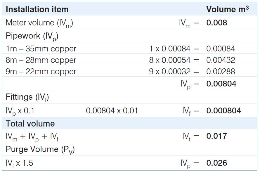
50 Calculating the PV Fittings Volume To calculate additional volume for fittings, valves, pressure vessels, accumulators etc. (IVf) add 10% of the IVp. Multiply the IVp by Having calculated the IVt, the purge volume (PV) can be calculated by multiplying the IVt by 1.5. Example A U6 diaphragm meter has an installation containing 1m of 35mm copper tube, 8m of 28mm copper tube and 9m of 22mm copper tube. (see next slide)
51 Calculating the PV
ACS.TPCP1A SAFETY ASSESSMENT CRITERIA INITIAL AND RE-ASSESSMENT NON-DOMESTIC NATURAL GAS TESTING AND PURGING
 ACS.TPCP1A SAFETY ASSESSMENT CRITERIA INITIAL AND RE-ASSESSMENT NON-DOMESTIC NATURAL GAS TESTING AND PURGING Issue 3.1 ACS.SMB 1 TPCP1A INITIAL & RE-ASSESSMENT Introduction Tests gas safety competencies
Overview EUSSAM12. Carry out tightness testing and direct purging of gas installations
 Overview This standard covers tightness testing and direct purging of low or medium pressure gas, in accordance with approved procedures and practices. It covers the standards required to meet the requirements
ACS.CoNGLP1 SAFETY ASSESSMENT CRITERIA INITIAL & RE-ASSESSMENT DOMESTIC NATURAL GAS TO LPG GENERIC
 ACS.CoNGLP1 SAFETY ASSESSMENT CRITERIA INITIAL & RE-ASSESSMENT DOMESTIC NATURAL GAS TO LPG GENERIC Issue 4.2 ACS. SMB 1 CoNGLP1 INITIAL & RE-ASSESSMENT Range All LPG fittings. Comprises: 2. Gas emergency
ACS.CoNGLP1 SAFETY ASSESSMENT CRITERIA INITIAL & RE-ASSESSMENT DOMESTIC NATURAL GAS TO LPG GENERIC
 ACS.CoNGLP1 SAFETY ASSESSMENT CRITERIA INITIAL & RE-ASSESSMENT DOMESTIC NATURAL GAS TO LPG GENERIC Issue 8.1 ACS. SMB April 2018 1 CoNGLP1 INITIAL & RE-ASSESSMENT Range All LPG fittings. Comprises: 2.
ACS.TPCP1 SAFETY ASSESSMENT CRITERIA INITIAL AND RE-ASSESSMENT NON-DOMESTIC NATURAL GAS; LPG; OTHER GASES TESTING AND PURGING
 ACS.TPCP1 SAFETY ASSESSMENT CRITERIA INITIAL AND RE-ASSESSMENT NON-DOMESTIC NATURAL GAS; LPG; OTHER GASES TESTING AND PURGING 1 TPCP1 INITIAL & RE-ASSESSMENT Introduction Tests gas safety competencies
Overview EUSDSG3.6. Gas tightness testing and direct purging
 Overview This national occupational standard is for gas engineers who will be carrying out tightness testing and direct purging of small(domestic) natural gas installations. This standard also covers the
Understanding gas safety
 Level: 3 Credit value: 15 URN: Y/502/8485 Unit aim This unit aims to provide learners with the knowledge and understanding of the gas safety requirements for working in the gas industry. Learning outcomes
Tightness testing and direct purging of small Liquefied Petroleum Gas/Air, Natural Gas and Liquefied Petroleum Gas installations
 Communication 1759 Tightness testing and direct purging of small Liquefied Petroleum Gas/Air, Natural Gas and Liquefied Petroleum Gas installations Founded 1863 Royal Charter 1929 Patron: Her Majesty the
G196 Series BASOTROL Redundant Combination Gas Valve with Manual Shutoff Valve
 Installation Instructions Issue Date August 19, 2008 G196 Series BASOTROL Redundant Combination Gas Valve with Manual Shutoff Valve Application The G196 valves are suitable for use with natural gas, Liquefied
G196 Series BASOTROL Redundant Combination Gas Valve with Manual Shutoff Valve
 Installation Instructions Issue Date March 13, 2013 G196 Series BASOTROL Redundant Combination Gas Valve with Manual Shutoff Valve Application The G196 valves are suitable for use with natural gas, Liquefied
SL G3. Warning
 Important: If converting from Propane to Natural Gas - order the Natural Gas Conversion Parts Kit (IBC Part # P-307) from your authorized IBC Distributor. Use the Propane Gas conversion parts kit if the
ACCESSORY KIT INSTALLATION INSTRUCTIONS
 ACCESSORY KIT INSTALLATION INSTRUCTIONS 1NP0680 - PROPANE CONVERSION FOR USE WITH MODELS: PM8, PC8, PM9, PC9, FL9M, FL9C, FC9M, FC9C This conversion kit is to be installed by a qualified service agency
INSTRUCTIONS FOR CONVERTING CONDENSING GAS MOBILE HOME FURNACES MODEL SERIES: CMA3*, CMC1*, VMA3*, VMC1*
 INSTRUCTIONS FOR CONVERTING CONDENSING GAS MOBILE HOME FURNACES MODEL SERIES: CMA3*, CMC1*, VMA3*, VMC1* THIS KIT CONTAINS: AOPS7741 (NATURAL TO PROPANE CONVERSION PARTS FOR MODEL SIZE, 50) AOPS7742(NATURAL
G96 Series BASOTROL Dual Operator Valve
 Installation Instructions 9. Issue Date February 22, 2013 G96 Series BASOTROL Dual Operator Valve Applications The G96 valves are combination, dual operator, automatic valves available with or without
SL G3 - Fuel Conversion to Natural Gas (LP to NG) P-Kit 301
 P-Kit 301") SL 26-260 G3 - Fuel Conversion to Natural Gas (LP to NG) P-Kit 301 Note If converting from Natural Gas to Propane, order the Natural Gas Conversion Parts Kit (IBC Part # P-300) from your authorized IBC
SL 26-260 G3 - Fuel Conversion to Natural Gas (LP to NG) P-Kit 301 Note If converting from Natural Gas to Propane, order the Natural Gas Conversion Parts Kit (IBC Part # P-300) from your authorized IBC
Gas Check. Short testing time, with automatic start-up if no leakage was detected from previous operation.
 Quality Products at Competitive Prices Gas Check Automatic testing of the down-stream installation to check that all valves are closed and that pipework and fittings are gas tight before each system start-up.
SL G3 - Fuel Conversion to Propane (NG to LP) P-Kit 302
 P-Kit 302") SL 40-399 G3 - Fuel Conversion to Propane (NG to LP) P-Kit 302 If converting from Propane to Natural Gas, order the Natural Gas Conversion Parts Kit (IBC Part # P-303) from your authorized IBC Distributor.
SL 40-399 G3 - Fuel Conversion to Propane (NG to LP) P-Kit 302 If converting from Propane to Natural Gas, order the Natural Gas Conversion Parts Kit (IBC Part # P-303) from your authorized IBC Distributor.
GM Series Dual-Block Multi-Function Gas Control Valves
 Installation Sheets Manual 121 Gas Combustion Combination Controls and Systems Section G Technical Bulletin GM Issue Date 0297 GM Series Dual-Block Multi-Function Gas Control Valves Figure 1: GM Series
PRESSURE REGULATOR LBM SERIES
 VIRTUAL CATALOGUE FAIL TO OPEN REGULATOR HIGH FLOW COEFFICIENT WIDE PRESSURE-REGULATION RANGE FAST RESPONSE PRESSURE REGULATOR LBM SERIES FULL SEAL AT ZERO FLOW CAN BE SUPPLIED WITH MINIMUM / MAXIMUM PRESSURE
INSTITUTION OF GAS ENGINEERS AND MANAGERS
 INSTITUTION OF GAS ENGINEERS AND MANAGERS UTILIZATION PROCEDURES ENHANCEMENTS. FEBRUARY 2009 (7 sides) These Enhancements apply to the following publications. However, it is not essential that these enhancements
Propane Conversion Kit Instruction
 Propane Conversion Kit Instruction Condensing gas boiler Required Input Rates Logamax plus GB62-80 kw 270,000 btu/hr Logamax plus GB62-00 kw 35,000 btu/hr This kit and instructions are for converting the
ACCESSORY KIT INSTALLATION MANUAL
 ACCESSORY KIT INSTALLATION MANUAL LP (PROPANE) CONVERSION KIT 1NP0366 FOR USE WITH MODELS: G8C & GF8 This conversion kit shall be installed by a qualified service agency in accordance with these instructions
OIL SUPPLY SYSTEMS ABOVE 45kW OUTPUT 4.1 Oil Supply
 OIL SUPPLY SYSTEMS ABOVE 45kW OUTPUT 4.1 Oil Supply 4.1.1 General The primary function of a system for handling fuel oil is to transfer oil from the storage tank to the oil burner at specified conditions
Propane Conversion Kit Instruction
 Propane Conversion Kit Instruction Condensing gas boiler Required Input Rates GB142-24 84,800 btu/hr GB142-30 106,000 btu/hr GB142-45 160,900 btu/hr GB142-60 214,800 btu/hr This kit and instructions are
LNVx Gas Conversion Kit Instructions
 TB134 Issue 1.0 Nov 2018 Applies to models: LNVx LNVx Gas Conversion Kit Instructions +44 (0) 1460 53535 info@powrmatic.co.uk www.powrmatic.co.uk General Information Heater conversion between gases will
Using propane cylinders safely
 Using propane cylinders safely This leaflet is for the safe use of Calor Gas propane cylinders. If you have any queries please contact your local retailer. Calor supplies Liquefied Petroleum Gas (LPG)
TB132. Gas Conversion Kits for NV & NVS Heaters. Issue 1.0 May Applies to models: NV & NVS
 TB132 Issue 1.0 May 2018 Applies to models: NV & NVS Gas Conversion Kits for NV & NVS Heaters www.powmatic.co.uk +44 (0) 1460 53535 info@powrmatic.co.uk General Information Heater conversion between gases
Overview EUSDSG3.12. Install gas meters and regulators (2.5 to 16.0m3/hr)
") Overview This national occupational standard is for gas engineerswho are required to install and exchange meters and regulators (2.5 to 16.0m3/hr) on low pressure and medium pressure gas systems. This
Overview This national occupational standard is for gas engineerswho are required to install and exchange meters and regulators (2.5 to 16.0m3/hr) on low pressure and medium pressure gas systems. This
A little technical and safety...
 A little technical and safety... Please familiarise yourself with the contents of this booklet as it references the safety of your tank installation and safe supply of LPG. Please also keep to hand a note
RE: PROPANE SYSTEM & REGULATOR TESTING/INSPECTION PROCEDURE
 March 22, 2013 RE: PROPANE SYSTEM & REGULATOR TESTING/INSPECTION PROCEDURE Regulators: Symptom: Pressure Drop Cause: External leaks detected at pigtail hose MPT fitting connection(s) to regulator body
GAS SUPPLY APPLICATION GUIDE
 GAS SUPPLY APPLICATION GUIDE Natural Gas or Propane Modulating & Condensing Boilers and Water Heaters This document applies to the following models: Boilers AM 399B AM 500B AM 750B AM 1000B Gas-Fired Boilers
VR46.5V(A)/VR86.5V(A) SERIES
/VR86.5V(A) SERIES") VR46.5V(A)/VR86.5V(A) SERIES COMACT COMBINATION GAS CONTROS WITH INTEGRATED 1:1 GAS/AIR REGUATOR FOR AUTOMATIC IGNITION SYSTEMS SECIFICATIONS INSTRUCTION SHEET Subject to change without notice. rinted
VR46.5V(A)/VR86.5V(A) SERIES COMACT COMBINATION GAS CONTROS WITH INTEGRATED 1:1 GAS/AIR REGUATOR FOR AUTOMATIC IGNITION SYSTEMS SECIFICATIONS INSTRUCTION SHEET Subject to change without notice. rinted
GAS SUPPLY DESIGN GUIDE
 GAS SUPPLY DESIGN GUIDE Natural Gas, Propane Gas, or Dual Fuel Fired Modulating, Condensing Boilers BENCHMARK Series Gas-Fired Boilers For models: BMK750 to BMK6000 Last Update: 06/20/2014 PR1 06/20/14
LPG TANK INFORMATION An energy company that puts
 LPG TANK INFORMATION An energy company that puts Safety first. LPG TANKS Thanks Thank you for choosing Kleenheat for your LPG supply. We consider safety our number one priority, so please make time to
G92 Series BASOTROL Automatic Pilot Gas Valve
 Installation Instructions Issue Date September 17, 2008 G92 Series BASOTROL Automatic Pilot Gas Valve Installation IMPORTANT: Only qualified personnel should install or service BASO Gas Products. These
POP Safety Valve. POP Safety Valve INTRODUCTION DEFINITIONS
 POP Safety Valve POP Safety Valve INTRODUCTION The effects of exceeding safe pressure levels in an unprotected pressure vessel or system, can have catastrophic effects on both plant and personnel. Safety
Propane Conversion Kit Instruction
 Propane Conversion Kit Instruction Condensing gas boiler Required Input Rates GB42-24 84,800 btu/hr Tab. GB42-30 06,000 btu/hr GB42-45 49,000 btu/hr GB42-60 24,800 btu/hr This kit and instructions are
Natural Gas High-Altitude Conversion Kit For Installations in the United States (2,001 10,000 Feet)
") Natural Gas High-Altitude Conversion Kit For Installations in the United States (2,001 10,000 Feet) INSTALLATION INSTRUCTIONS For R7 Series Light Commercial Packaged Gas Electric Units IIMPORTANT: Please
Natural Gas High-Altitude Conversion Kit For Installations in the United States (2,001 10,000 Feet) INSTALLATION INSTRUCTIONS For R7 Series Light Commercial Packaged Gas Electric Units IIMPORTANT: Please
ACCESSORY KIT INSTALLATION INSTRUCTIONS
 ACCESSORY KIT INSTALLATION INSTRUCTIONS PROPANE CONVERSION - INDUCED COMBUSTION FURNACES 1NP0501 FOR USE WITH 95% MODELS: TG9S, GG9S (130,000 BTU ONLY) FOR USE WITH 80% MODELS: TG(8,L)S, GG(8,L)S (130,000
INSTITUTION OF GAS ENGINEERS AND MANAGERS
 INSTITUTION OF GAS ENGINEERS AND MANAGERS IGEM/UP AND IGE/UP SERIES OF STANDARDS AMENDMENTS. OCTOBER 2012 (31 sides) Amendments apply to the following Standards: IGE/UP/1 Edition 2. Communication 1683
Your safety and the safety of others are very important.
 NATURAL GAS TO PROPANE CONVERSION KIT ALPKT57- INSTALLATION INSTRUCTIONS PROPANE CONVERSION KIT SAFETY... INSTALLATION REQUIREMENTS... Tools and Parts... LP Gas Requirements... Table of Contents INSTALLATION
WARNING: Installation Instructions. Natural Gas High Altitude Conversion Kit United States Installations Only
 Natural Gas High Altitude Conversion Kit United States Installations Only Installation Instructions Light Commercial Packaged Gas Electric Units R7TQ Series 6, - 7 1/2, & 10 Ton (2,001 FT - 10,000 FT)
INSTALLATION INSTRUCTIONS MANUAL ON/OFF SAFETY VALVE/PILOT KIT MODEL GA9050A-1 (F0235)
") P/N 126905-01 Rev. B 11/2016 INSTALLATION INSTRUCTIONS MANUAL ON/OFF SAFETY VALVE/PILOT KIT MODEL GA9050A-1 (F0235) For All Single, Dual and Triple Burner Natural and Propane/LP Gas Logs P126905-01 For
P/N 126905-01 Rev. B 11/2016 INSTALLATION INSTRUCTIONS MANUAL ON/OFF SAFETY VALVE/PILOT KIT MODEL GA9050A-1 (F0235) For All Single, Dual and Triple Burner Natural and Propane/LP Gas Logs P126905-01 For
36E DSI, HSI & Proven Pilot Two-Stage Combination Gas Valve INSTALLATION INSTRUCTIONS
 INLET PRESS TAP WTE-RODGERS 36E96-314 DSI, HSI & Proven Pilot Two-Stage Combination Gas Valve INSTALLATION INSTRUCTIONS Operator: Save these instructions for future use! FAILURE TO READ AND FOLLOW ALL
36E DSI and HSI Two-Stage Combination Gas Valve INSTALLATION INSTRUCTIONS
 INLET PRESS TAP WTE-RODGERS 36E54-214 DSI and HSI Two-Stage Combination Gas Valve INSTALLATION INSTRUCTIONS Operator: Save these instructions for future use! FAILURE TO READ AND FOLLOW ALL INSTRUCTIONS
/2004 US/CA
 630 9765 0/004 US/CA For the contractor Propane Conversion Kit Instructions Sealed Combustion Gas Boiler Logano GA44 This kit and instructions are for converting the GA44 model boilers from Natural Gas
Network Regulator Maintenance Operatives LS (Non-Accredited)
") Background Network Regulator Maintenance Operatives LS (Non-Accredited) Network Maintenance Operative (NMO) would be trained to perform work on pressure reducing equipment upstream of the ECV on pressures
Background Network Regulator Maintenance Operatives LS (Non-Accredited) Network Maintenance Operative (NMO) would be trained to perform work on pressure reducing equipment upstream of the ECV on pressures
TECHNICAL DATA. Q= Cv S
 Page 1 of 13 1. DESCRIPTION The Viking 4 inch Model G-4000 Dry Valve Riser Assembly consists of a small profile, light weight, pilot operated valve that is used to separate the water supply from the dry
SIZING AND CAPACITIES OF GAS PIPING
 SIZING AND CAPACITIES OF GAS PIPING A.1 General piping considerations. The first goal of determining the pipe sizing for a fuel gas piping system is to make sure that there is sufficient gas pressure at
36H SERIES Combination Gas Valve
 FAILURE TO READ AND FOLLOW ALL INSTRUCTIONS CAREFULLY BEFORE INSTALLING OR OPERATING THIS CONTROL COULD CAUSE PERSONAL INJURY AND/OR PROPERTY DAMAGE. DESCRIPTION The 36H series combination gas valve is
TECHNICAL DATA. Q = C v P S
 Page 1 of 13 1. DESCRIPTION The Viking 6 Model G-6000 Dry Valve Riser Assembly consists of a small profile, light weight, pilot operated valve that is used to separate the water supply from the dry sprinkler
REGISTRATION EXAMINATION, NOVEMBER 2017 TRADESMAN GASFITTER QUESTION AND ANSWER BOOKLET. Time allowed THREE hours
 Affix label with Candidate Code Number here. If no label, enter candidate Number if known No. 99 REGISTRATION EXAMINATION, NOVEMBER 07 TRADESMAN GASFITTER INSTRUCTIONS QUESTION AND ANSWER BOOKLET Time
GM-7000 Series CE Approved Gas Control Valve
 Installation Instructions GM-7000 Issue Date November 9, 2012 GM-7000 Series CE Approved Gas Control Valve Installation IMPORTANT: These instructions are intended as a guide for qualified personnel installing
O.K. Safety first CDN USA. Table of Contents. Approvals. Attention IFGC CSA UL ANSI NFPA
 S06 & S02 Valve Proving System Installation Instructions USA CDN Table of Contents Table of Contents... Page 1 Approvals... Page 1 Attention... Page 1 Specification... Page 2 Mounting.... Page 3 Wiring...
TECHNICAL DATA 3 MODEL G-3000 DRY VALVE RISER ASSEMBLY
 Page 1 of 13 1. DESCRIPTION The Viking 3 Model G-3000 Dry Valve Riser Assembly is equipped with a small profile, light weight, pilot operated valve that is used to separate the water supply from the dry
Radiator thermostats type RA2000, valve bodies type RA-FN (series D) and RA-G
 and RA-G") Data sheet Radiator thermostats type RA2000, valve bodies type RA-FN (series D) and RA-G EN 215 Application RA2000 013G2910 Built-in sensor RA2000 013G2920 tamperproof RA2000 013G5062 remote temperature
Data sheet Radiator thermostats type RA2000, valve bodies type RA-FN (series D) and RA-G EN 215 Application RA2000 013G2910 Built-in sensor RA2000 013G2920 tamperproof RA2000 013G5062 remote temperature
Operator: Save these instructions for future use!
 WHITE-RODGERS Type 36C67 Combination (24 Volt Models) INSTALLATION INSTRUCTIONS Operator: Save these instructions for future use! FAILURE TO READ AND FOLLOW ALL INSTRUCTIONS CAREFULLY BEFORE INSTALLING
KC Series Gas Components and Supply Design Guide
 Technical Bulletin KC Series Gas Components and Supply Design Guide GF-1030 General AERCO KC Series gas fired potable water heaters and boilers are modulating input devices that require an adequate volume
TECHNICAL DATA Q = C. v P S. 2 Model G-2000 Dry valve. Page 1 of 13
 Page 1 of 13 1. Description The Viking 2 Model G-2000 Dry Valve Riser Assembly consists of a small profile, light weight, pilot operated valve that is used to separate the water supply from the dry sprinkler
Natural Gas Conversion Kit
 SERIAL #: Attention: Centro recommends that a qualified gas technician perform the gas supply conversion and orifice replacement for this BBQ model. Natural Gas Conversion Kit F O R U S E W I T H M O D
User Information Sheet 015
 User Information Sheet 015 Formerly LPGA Guidance NO.84 March 2007 Inspection and Maintenance of LPG Pipework at Commercial and Industrial Premises 1. Introduction LPG pipework may, under certain conditions,
Installation Instructions WARNING: WARNING: WARNING: LP AND HIGH ALTITUDE LP GAS CONVERSION KIT FOR UNITED STATES INSTALLATIONS
 LP AND HIGH ALTITUDE LP GAS CONVERSION KIT FOR UNITED STATES INSTALLATIONS Installation Instructions For Model Series *G7/*GC2 Furnaces and Appliances Using Honeywell Gas Valves. BEFORE THE CONVERSION
ARCHIVED. Compliance Document for New Zealand Building Code Clause G11 Gas as an Energy Source. Prepared by the Department of Building and Housing
 Compliance Document for New Zealand Building Code Clause G11 Gas as an Energy Source Prepared by the Department of Building and Housing This Compliance Document is prepared by the Department of Building
Cover Page for Lab Report Group Portion. Pump Performance
 Cover Page for Lab Report Group Portion Pump Performance Prepared by Professor J. M. Cimbala, Penn State University Latest revision: 02 March 2012 Name 1: Name 2: Name 3: [Name 4: ] Date: Section number:
For use with select HPC Fire Pits ONLY- refer to product catalog or website. 100K BTU Maximum WARNING: FOR OUTDOOR USE ONLY
 For use with select HPC Fire Pits ONLY- refer to product catalog or website. 100K BTU Maximum : FOR OUTDOOR USE ONLY Small Tank LP Kit (STLPK) Installation & Operation Instructions Installation We suggest
Welcome to Calor Information on your business gas supply
 Welcome to Calor Information on your business gas supply 2 3 Contents 4 Welcome to Calor 6 Your gas delivery 7 Your gas bill cylinder & bulk 8 Gas storage and maintenance 10 Looking after cylinders 12
SUMMITTM 400 & 600. Natural Gas Barbecues. Step-By-Step Guide
 SUMMITTM 400 & 600 Natural Gas Barbecues Step-By-Step Guide W E B E R W E B E R W E B E R W E B E R Summit 400 NG Summit 600 NG CANADIAN GAS ASSOCIATION R A P P R O V E D WARNING: Follow all leak check
Instruction Manual VCG-6
 Specifications Amps / Volts requirements 400 ma @ 24 VDC Propane pressure (VCG-6LP) 11 WC / 2.8 kpa Natural Gas pressure (VCG-6NG) 4.5 WC / 1.15 kpa Cu ft per hour / CO2 3-6 SCFH BTU Rating (Variable)
EDUCATION DEPARTMENT ACCU-TEST
 ABN 17 100 208 964 EDUCATION DEPARTMENT ACCU-TEST GAS SAFETY SHUT OFF SYSTEM Operating & Installation Manual Head Office (Melbourne) Sydney Brisbane (Distributor) 1/5 Samantha Court 2/14 Welder Road 17
Un-Pressurized Orefice Fittings FIO EZ. Parts List and Operation Instructions TECHNICAL MANUAL. Dn 2-6 Class Lbs
 Un-Pressurized Orefice Fittings FIO EZ Parts List and Operation Instructions TECHNICAL MANUAL Dn 2-6 Class 150-600 Lbs US US 2 FIO EZ - MT 108-US - 05-2016 FIO EZ Important Instructions US Pietro Fiorentini
SIZING AND CAPACITIES OF GAS PIPING
 APPENDIX A (IFGS) SIZING AND CAPACITIES OF GAS PIPING (This appendix is informative and is not part of the code. This appendix is an excerpt from the 2003 International Fuel Gas Code, coordinated with
Compiled by: B Beard. Approved by: SH Carstens. Description of requirements and procedures for compact provers to be used as verification standards.
 1. Scope Description of requirements and procedures for compact provers to be used as verification standards. 2. Reference documents Trade Metrology Act SANS1698 3. Policy A. BASIC REQUIREMENTS Compact
CRAFTSMAN EXAMINATION, NOVEMBER 2007 GASFITTING ANSWER SCHEDULE
 No. 9196 CRAFTSMAN EXAMINATION, NOVEMBER 2007 GASFITTING ANSWER SCHEDULE Plumbers, Gasfitters and Drainlayers Board, 2007. All rights reserved. No part of this publication may be reproduced by any means
PRESSURISED PAINT CONTAINER
 PRESSURISED PAINT CONTAINER MODEL NO: CPP2B PART NO: 3082115 OPERATION & MAINTENANCE INSTRUCTIONS GC0913 INTRODUCTION Thank you for purchasing this CLARKE Pressurised Paint Container. Before attempting
SIZING AND CAPACITIES OF GAS PIPING
 APPENDIX A (IFGS) SIZING AND CAPACITIES OF GAS PIPING (This appendix is adopted as part of the code.) A.1 General. To determine the size of piping used in a gas piping system, the following factors must
WARNING: Gas Conversion Kit Instructions Applies to: Model UDAP, UDAS, UDBP, and UDBS Unit Heaters. General and Warnings FOR YOUR SAFETY
 Form CP-UD-GC Obsoletes I-UD-GC (Version E) Gas Conversion Kit Instructions Applies to: Model UDAP, UDAS, UDBP, and UDBS Unit Heaters General and Warnings All gas conversion must be done by a qualified
Dual Solenoid Gas Valve Installation
 Installation IMPORTANT: These instructions are intended as a guide for qualified personnel installing or servicing FLYNN Gas Products. Carefully follow all instructions in this bulletin and all instructions
Dival 500 Pressure Regulators
 Dival 500 Pressure Regulators Dival 500 Classification and Range of use The DIVAL 500 is a downstream direct-acting pressure regulator with balanced plug, for low, medium and high pressures. Suitable for
Operator: Save these instructions for future use!
 WHITE-RODGERS Type 36C04, 36C14 Step-Opening Combination Gas Control (24 Volt, 120 Volt & 750 mv Models) INSTALLATI INSTRUCTIS Operator: Save these instructions for future use! FAILURE TO READ AND FOLLOW
Thank You for Attending Today s Webinar. Today s Featured Speaker
 Thank You for Attending Today s Webinar Your Host Mike DeLacluyse President Lesman Instrument Company miked@lesman.com Today s Featured Speaker A.J. Piskor Combustion & Controls Specialist Lesman Instrument
Experiment 8: Minor Losses
 Experiment 8: Minor Losses Purpose: To determine the loss factors for flow through a range of pipe fittings including bends, a contraction, an enlargement and a gate-valve. Introduction: Energy losses
Installation, Operation and Maintenance Instructions for Electronically Controlled Pressurisation Units
 Installation, Operation and Maintenance Instructions for Electronically Controlled Pressurisation Units Models: EPS Single Pump EPT Twin Pump EPS-HP EPT-HP Single Pump High Pressure Twin Pump High Pressure
SPECIFICATIONS ATTENTION
 VPS 504 S06 Installation Manual - P/N 80122 - Ed. 01/09 VPS 504 S06 and S05 Valve Proving System Installation Instructions VPS 1 6 Gases Natural gas, air and other inert gases. NOT suitable for butane
Instruction Manual No. 742, 8/98
 Instruction Manual No. 742, 8/98 Eclipse Ratio Regulators ES Series COPYRIGHT Copyright I997 by Eclipse Combustion, Inc. All rights reserved worldwide. This publication is protected by federal regulation
Cover Page for Lab Report Group Portion. Head Losses in Pipes
 Cover Page for Lab Report Group Portion Head Losses in Pipes Prepared by Professor J. M. Cimbala, Penn State University Latest revision: 02 February 2012 Name 1: Name 2: Name 3: [Name 4: ] Date: Section
VS8420 Millivolt Gas Valve
 VS8420 Millivolt Gas Valve INSTALLATION INSTRUCTIONS APPLICATION The VS8420 Millivolt Gas Valve is compact and has a 60,000 Btuh capacity (1 in. pressure drop for straightthrough configuration). The design
V5197A. Firing Rate Gas Valve APPLICATION FEATURES PRODUCT HANDBOOK
 V5197A Firing Rate Gas Valve PRODUCT HANDBOOK APPLICATION The V5197A are firing rate valves used to provide variable flow control of air, natural gas, liquefied petroleum (LP), and manufactured gases.
Operator: Save these instructions for future use!
 WHITE-RODGERS Operator: Save these instructions for future use! FAILURE TO READ AND FOLLOW ALL INSTRUCTIS CAREFULLY BEFORE INSTALLING OR OPERATING THIS CTROL COULD CAUSE PERSAL INJURY AND/OR PROPERTY DAMAGE.
36C/36D HSI, DSI Proven Pilot Gas Valves INSTALLATION INSTRUCTIONS
 36C/36D HSI, DSI Proven Pilot Gas Valves INSTALLATION INSTRUCTIONS Operator: Save these instructions for future use! FAILURE TO READ AND FOLLOW ALL INSTRUCTIONS CAREFULLY BEFORE INSTALLING OR OPERATING
PRESSURE TEST PUMP OPERATING & MAINTENANCE INSTRUCTIONS. Model No: PTP100. Part No: GC01/09
 PRESSURE TEST PUMP Model No: PTP00 Part No: 06020 OPERATING & MAINTENANCE INSTRUCTIONS GC0/09 INTRODUCTION Thank you for purchasing this CLARKE Pressure Testing Pump. Before attempting to use the product,
Operator: Save these instructions for future use!
 INLET PRESS TAP WHITE-RODGERS 36E93-304 Delay-Opening Combination Gas Valve INSTALLATION INSTRUCTIONS Operator: Save these instructions for future use! FAILURE TO READ AND FOLLOW ALL INSTRUCTIONS CAREFULLY
SV60 Safety valves. for use with steam, gas and liquids
 SV60 Safety valves for use with steam, gas and liquids Spirax Sarco safety valves - protecting people, plant and profit The SV60 spring loaded full lift safety valve range from Spirax Sarco has been designed
Level MEASUREMENT 1/2016
 Level MEASUREMENT 1/2016 AGENDA 2 A. Introduction B. Float method C. Displacer method D. Hydrostatic pressure method E. Capacitance method G. Ultrasonic method H. Radar method I. Laser method J. Level
Radiator thermostats type RA2000, valve bodies type RA-FN (series D) and RA-G
 and RA-G") Data sheet Radiator thermostats type RA2000, valve bodies type RA-FN (series D) and RA-G Application RA2000 013G2910 Built-in sensor RA2000 013G2920 tamperproof RA2000 013G5062 remote temperature adjuster
Data sheet Radiator thermostats type RA2000, valve bodies type RA-FN (series D) and RA-G Application RA2000 013G2910 Built-in sensor RA2000 013G2920 tamperproof RA2000 013G5062 remote temperature adjuster
VR8205S,T Direct Ignition Combination Gas Controls
 VR805S,T Direct Ignition Combination Gas Controls INSTALLATION INSTRUCTIONS APPLICATION TheVR805S,T Direct Ignition Combination Gas Controls are used in gas-fired appliances with up to 70 ft 3 /hr capacity
ECONORESS ELECTRONIC EPS & EPT - ENHANCED PRESSURISATION SET INSTALLATION OPERATION & MAINTENANCE DOCUMENTATION
 ECONORESS ELECTRONIC EPS & EPT - ENHANCED PRESSURISATION SET INSTALLATION OPERATION & MAINTENANCE DOCUMENTATION OCT2010 STOKVIS ENERGY SYSTEMS 96R WALTON ROAD EAST MOLESEY SURREY KT8 0DL TEL: 020 87833050
INSTALLATION OPERATION MAINTENANCE
 Bermad Electrically Controlled On-Off Deluge Valve Model: 400E-3D INSTALLATION OPERATION MAINTENANCE Application Engineering BERMAD 1. Safety First BERMAD believes that the safety of personnel working
Summary of Substantive Changes between the 2004 e1 and 2017 editions of ASSE 1011, Hose Connection Vacuum Breakers
 Summary of Substantive Changes between the 2004 e1 and 2017 editions of ASSE 1011, Hose Connection Vacuum Breakers Presented to the IAPMO Standards Review Committee on October 15, 2018 General: The changes
BGA158 Series CE Approved Class B Shutoff Gas Valve
 Installation Instructions BGA158 Issue Date March 22, 2016 BGA158 Series CE Approved Class B Shutoff Gas Valve Applications The BGA158 Series shutoff gas valve is an electrically operated shutoff valve
Installation Instructions and User Guide 15mm & 22mm Thermostatic Mixing Valve
 Installation Instructions and User Guide 15mm & 22mm Thermostatic Mixing Valve TMV3 / TMV2 Combined Valve C85079 C85081 C85080 C85082 It is important that these guidance notes are read and fully understood