SEPAREL. Hollow Fiber Membrane Module INSTRUCTION MANUAL (For IJ) EF External Flow Small Size Series. EF-MICRO EF-G2 Series EF-G3 Series EF-G5 Series
|
|
|
- Caitlin Higgins
- 5 years ago
- Views:
Transcription


1 SEPAREL Hollow Fiber Membrane Module (For IJ) EF External Flow Small Size Series EF-MICRO EF-G2 Series EF-G3 Series EF-G5 Series Before using the SEPAREL EF small size series, be sure to read this instruction manual to ensure safe and proper use. DIC will not have any liability to a customer or end user in connection with any costs and damages arising directly or indirectly from any defective modules. We are not responsible for any usage, installation, or any other handling done by the customer. The module must be used, installed, and handled responsibly by the customer. Ver June 3,
2 About this Instruction Manual This instruction manual explains how to handle SEPAREL EF small size degassing modules, such as the EF-MICRO, EF-G2, EF-G3, and EF-G5 series, with precautions to be followed for your safety. Before using the SEPAREL EF small size series, be sure to read this instruction manual to ensure safe and proper use. Depending on use conditions, proper methods for usage and storage may differ even though there are descriptions about usage methods, storage methods, and risks associated with the product module within this manual. Please note that this manual does not describe all information about risks related to usage and storage of the product. Although the content of this instruction manual is based on reliable testing and measurement results, no guarantees are provided for its accuracy. DIC does not have any responsibility for anything described or not described in this manual. The details of this instruction manual may be modified for improved reliability of the SEPAREL EF series or to account for changes in its design. 2 2
3 Warranty, Warranty Period Warranty At the time of delivery, DIC warrants that the Separel module will be free from defects in material and workmanship and meet the specifications supplied to the customer by DIC. Warranty Period The following Warranty Period is applied only if customer use of the Separel module is in accordance with the instructions contained in this manual, the specification sheet, any applicable Cleaning Guides and the Warranty Statement. (1) Water Maximum 12 months from the date of delivery of the module - This warranty period is applied only if customer refers to P.11, 3-3 (1). - The above warranty will be voided in the event that water of unspecified quality is used. (2) Liquids other than water - Water-Based Liquid : Maximum 12 months from the date of delivery of the module*1 - Non-Water-Based Liquid : Maximum 6 months from the date of delivery of the module*1 *1 The warranty periods shown above are strictly to demonstrate the maximum warranty period available for the modules. Any actual warranty period will be based upon the results of compatibility tests of the module with all liquids which may come in contact with the module. The compatibility testing procedures will be informed to the customer by DIC. It is the customer s responsibility to conduct the compatibility tests and provide the results thereof to DIC. In accordance with the results of the compatibility test, any warranty period will be determined through consultations between DIC and the customer. DIC and the customer will agree in writing to the warranty period, as well as, terms of use for the module ( Warranty Statement ). If a liquid other than water (2) is used, only several SEPAREL products are applicable please refer to Table 1 below. 3 3
4 Warranty Remedy During the applicable warranty period as specified in the Warranty Statement, any defective module will be replaced free of charge by DIC in cases where a defect is found under normal use in accordance with this instruction manual and under use and storage conditions specified in the specification sheet and Warranty Statement. This is the sole remedy available to the customer under this warranty. DIC will not have any liability to a customer or end user in connection with any costs and damages arising directly or indirectly from any defective modules. We are not responsible for any usage, installation, or any other handling done by the customer. The module must be used, installed, and handled responsibly by the customer. The above warranty will be voided in the event that a liquid which has not been specified for use between the customer and DIC, as specified in the Warranty Statement, is used in the module or by any other use, installation or handling that is not in accordance with the instructions contained in this manual, the specification sheet and Warranty Statement. This module is consumable. DIC recommends that customers replace the module within the warranty period. Regarding Reproduction and Photocopying of this Manual Reproduction of this manual in whole or in part is strictly prohibited. The content of this manual are subject to change without notice. SEPAREL is a registered trademark of the DIC Corporation. 4 4
5 Contents 1. General Precautions P Upon Receipt P Installation P Start-Up P Shutoff and Storage P Restart P Maintenance P. 11 Reference Data 1. Basic Principles of Degassing P Vacuum Pressure Degree P Setting Value of Vacuum Pressure Degree P Range of Liquid Flow Rate P Inner Volume P Trouble shooting P.16 Contacts P
6 1. BASIC PRECAUTIONS 1-1. Maintain use, handling, and storage conditions described in specifications SEPAREL is consumable. We recommend replacement within the warranty period We are not responsible for any usage, installation, or other handling done by the customer. Make sure that the product is used, installed, and handled responsibly Do not feed the following liquids into SEPAREL oxidizing agents (highly concentrated chlorine water, ozone water, etc.), strong acids, strong bases, organic solvents, alcohol, oils, or any other liquid which is not compatible with the liquid and materials that SEPAREL modules are composed of Do not remove the end-cap of SEPAREL modules.. In cases where liquid that has not been deemed compatible by DIC is used, no warranty will apply to the product. 2. UPON RECEIPT 2-1. Check the label and shape of the module to confirm that the type and series number are the same as that of which you ordered Check whether no damage was sustained during transportation. If you find any damage, notify your sales representative immediately Do not physically shock or shake the SEPAREL module during unloading or storage. 6 6
7 3. INSTALLATION 3-1. Place of Installation: Install SEPAREL in accordance with conditions specified in the specification sheet, No exposure to direct sunlight No physical shock or shaking No contact with dust, moisture, corrosive gas, or liquid Easy access for maintenance, inspection, repair, and replacement 3-2. Method of Installation: Set the vacuum port downward to smoothly purge liquid derived from vapor. If you fix SEPAREL with a U-band, make sure not to loosen the fitting. Do not apply too much pressure when fixing SEPAREL with a U-band as too much pressure may damage the module. Putting a cushion between SEPAREL and U-band may prevent damage to the module Connection of the SEPAREL Module: Clean pipe/tube before connecting to prevent/remove dust, rust, oil, etc. Do not apply too much pressure to the connection. Do not shake or shock the SEPAREL module. Shaking or shocking SEPAREL may damage the module even if it is a light impact. Because the housing of the SEPAREL module is composed of PP, polypropylene, excess pressure to the connector may cause damage to the connecting port. Excess pressure to connecting port may shave thread and cause resin particles to appear in the liquid side. Do not touch hollow fibers. When you add a connector, adjust the insertion depth and not the screw part to touch hollow fibers. If the screw part touches the hollow fibers, the hollow fibers may become damaged. Depending on the type of connector, recommended conditions of connector insertion may differ. For detailed conditions, including torque value, contact us. The liquid feeding pump is recommended to be placed in front of the SEPAREL module. When you uninstall the SEPAREL module, be careful to not damage it. 7 7
8 3. INSTALLATION <Example of Installation> Filter Liquid Feeding Pump Degassing Module Filter Vacuum Meter Leak Valve Liquid Tank Vacuum Pump Trap The above example is for your reference. Depending on use conditions, the above example may not be suitable. Optimal flow direction differs by use conditions and the above flow direction is not always the correct direction. For suitable flow direction, contact us. 8 8
9 3. INSTALLATION 1)Liquid In: Install security devices, such as a pressure reducing valve and/or safety valve, to make sure that pressure will not be beyond the maximum operatingpressure. If you use a solenoid valve, select one which dose not cause sudden opening/shutting. If you use two modules in parallel, properly measure the liquid flow into both modules and ensure that liquid flow is equal. If impurities and large particles remain in liquid, install a filter in front of the SEPAREL module. Use RO water or higherqualitywater for the water supply. In the event water of a water quality lower than RO water is used: 1Please ensure the remaining chloride concentration is, 1mg/L". You can use water with over 1mg/L, but any warranty period will be determined through consultations between DIC and the customer. 2 To stop performance degradation by fouling in the film surface and clogging by particle debris, please refer to the following table and use a pre-filter. Specifically, since soluble compounds included in well water, a branch and tap water are easy to penetrate filtration and adhere to the surface of the filtration membrane, please use water in combination with the recommendations in following table. If you have any questions, please contact DIC Corporation. Liquid in phase 1.0 micron filter 2) Liquid Out: There is a possibility that particles are generated by the SEPAREL module. To prevent a problem with such particle occurrence, install a filtration filter behind the module. The most suitable filtration size depends on your use conditions. For more details, please contact DIC. Note that back pressure to the SEPAREL module should be avoided. 3)Vacuuming: Installed vacuum lines must always be facing downwards. If it is pointed upwards, liquid generated from vapor may block the vacuum line. Install a trap to detect leaked liquid and to prevent the vacuum pump from damage due to vapor and leaked liquid. A trap is also effective in preventing leaked liquid from feeding into other modules using the same vacuum line. 9 9
10 4. START UP 4-1. Open a valve on the outlet side first. Next, open a valve on the inlet side gradually to make the liquid flow rate and pressure lower than the designated value for actual use until liquid is filled. Do not flow liquid at a very high flow rate nor at a very high pressure. Even if it is instantaneous, very high flow rates or pressure may damage hollow fibers and cause leakage. For efficient removal of remaining air in the liquid area of SEPAREL modules, filling the liquid with a vacuum is recommended. During the vacuuming process, check the airtightness of the vacuum line and not the air that is leaked from pipe, connector, and SEPAREL module Observe liquid quality, temperature, and pressure specified in the specification sheet Do not flow oxidizing agents, such as highly concentrated chlorine water and ozone water, strong acids, strong bases, organic solvents, oil, or any other liquid which has not been confirmed as compatible by DIC. The warranty will not apply if liquid, which has not been confirmed as compatible by DIC, is used Do not change the flow rate dramatically in order to ensure that the hollow fibers are not damaged by drastic pressure fluctuations If vacuum pressure is very strong, and conditions are close to a perfect vacuum situation, stop the vacuum pump when liquid flow has stopped. Strong vacuuming for an extended period of time without liquid flow may freeze and damage hollow fibers via vaporization heat and liquid may leak from the damaged hollow fibers Check the items below periodically. If obvious deterioration is found, replace with a new degassing module. Item Liquid Inlet Pressure Liquid Temperature Pressure Drop Drain/Trap in Vacuum Line Points to be Checked Do not exceed maximum pressure specified in the specification sheet. Do not exceed the maximum temperature specified in the specification sheet. Do not fall below the minimum temperature specified in the specification sheet. Significant increase from initial value may be caused by clogging of hollow fiber or liquid flow path. In this case, replacement or cleaning is necessary. Continuous leaking of liquid to the vacuum means the product is reaching the end of its lifetime and replacement with a new degassing module is necessary
11 5. SHUTOFF AND STORAGE 5-1. Open the leak valve in the vacuum line. After vacuum is released, stop the vacuum pump Close the valve on the ink inlet side and then close the valve on the liquid outlet side Handling during Shutoff Period: 1) Store under the conditions specified by the specification sheet. 2) If the shutoff period is extensive, remove the SEPAREL modules and store after cleaning and drying completely. If it is difficult to uninstall the SEPAREL module, fill it with liquid that is compatible with SEPAREL and close all liquid and vacuum ports completely. Even liquid that is compatible with degassing module materials can lead to bacteria generation if it is left in the module during shutoff periods. The generation of bacteria may have a negative impact on product quality

12 REFERENCE DATA 1: Basic Principles of Degassing Liquid IN/OUT Image of Hollow Fiber Cross-section Sealing Resin Liquid Liquid Liquid IN/OUT Hollow Fiber Membrane Hollow Fiber Membrane Inside of Hollow Fiber for Vacuuming Hollow Fibers Vacuuming Sealing Resin By vacuuming inside the hollow fiber, only gas can pass through hollow fiber membrane and is removed from liquid. : Dissolved gas 12 12
13 REFRENCE DATA 2: Vacuum Pressure Degree Note that the vacuum pressure degree in our data sheet is mainly indicated by absolute pressure, not by gauge pressure. Recommended range of vacuum pressure degree (Refer to Reference Data 3) Absolute Pressure 1 atm =101.3 kpa(abs) = 1013 mbar(abs) = 760 Torr 0.65 atm = 65.8 kpa(abs) = 658 mbar(abs) = 494 Torr 0.35 atm = 35.5 kpa(abs) = 355 mbar(abs) = 266 Torr 0 Atmosphere Pressure Perfect Vacuum Pressurization Vacuuming Gauge Pressure atm = kpa = mbar = Torr atm = kpa = mbar = Torr - 1 atm = kpa = mbar = Torr < Absolute Pressure> For vacuuming conditions, every value should be 0 or plus. It cannot be minus. <Gauge Pressure> For vacuuming conditions, every value should be 0 or minus. It cannot be plus. (Reference: Absolute pressure -Gauge pressure =1atm) The value for maximum pressure resistance is indicated by gauge pressure
14 REFRENCE DATA 3: Setting Value of Vacuum Pressure Degree As the vacuum pressure degree approaches a perfect vacuum, degassing performance is improved. However, if the vacuum pressure degree is too strong yet close to perfect pressure, liquid may evaporate and penetrate through the membrane. As a result, the composition of liquids may change. Therefore, DIC recommends following the exact vacuum pressure degree. 1. For Water or Aqueous Liquid Recommended Degree of Vacuum: 5kPa(abs) ~ 10kPa(abs) = 50mbar(abs) ~ 100mbar(abs) The above pressure is the recommended value when using the module at When using the module at temperatures lower than 15 or higher than 30, please contact DIC for more details. The above vacuuming pressure is not suitable for every application. Depending on applications, composition, and target degassing performance, the most suitable vacuuming value may be different from the above value. <Reference: Saturated Water Vapor Pressure> Temperature ( ) kpa(abs) Torr mbar For Non-Aqueous Liquid. Recommended Vacuuming Degree: We recommend setting weaker degrees (higher in value) than the recommended saturated vapor pressure of the liquid. Ex:In cases where saturated vapor pressure is 8kPa(abs), we recommend a weaker vacuum degree than 10kPa(abs)
15 REFERENCE DATA 4: Range of Liquid Flow Rate Make sure that the liquid feeding pressure at the inlet port is lower than the maximum pressure value described in the specification sheet. If the feeding pressure exceeds the maximum value, even momentarily, the hollow fiber may be damaged and ink may leak into the vacuum line. The warranty will not apply in cases where liquid feeding pressure exceeds the maximum pressure value specified in the specification sheet, Product EF-MICRO EF-G2 Series EF-G3 Series EF-G5 Series Maximum Pressure Resistance 0.2 MPa (= 2 bar) 0.2 MPa (= 2 bar) 0.2 MPa (= 2 bar) 0.2 MPa (= 2 bar) Even if liquid feeding pressure is lower than the specified maximum pressure, an increased flow rate will cause lesser degassing performance. On the other hand, if the flow rate is too low, degassing cannot be efficient. Therefore, DIC supplies recommended flow ranges in the table below. The recommended flow range below was calculated when using water. In the case of high viscosity liquid, a suitable flow range will be more narrow. Product EF-MICRO EF-G2 series EF-G3 series EF-G5 series Flow area 0.5 ~ 10 ml/min 1 ~ 60 ml/min 5 ~ 300 ml/min 10 ~ 1500 ml/min 15 15
16 REFERENCE DATA 5: Inner Volume Product EF-MICRO EF-G2 Series EF-G3 Series EF-G5 Series Inner Volume at Liquid Part Approx. 4 ml Approx. 11 ml Approx. 40 ml Approx. 85 ml The above values are for reference and are not guaranteed values. Actual volume may differ by connection type


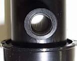
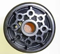
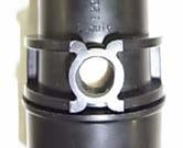
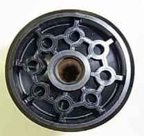
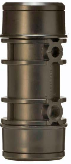
17 REFERENCE DATA 6: Image of Connecting Port EF MICRO EF G2 Series Liquid IN/OUT Liquid IN/OUT Liquid IN/OUT Liquid IN/OUT Vacuum Port Vacuum Port EF G3 Series EF G5 Series Liquid IN/OUT Liquid IN/OUT Liquid IN/OUT Liquid IN/OUT Vacuum Port Vacuum Port 17 17
18 Contacts DIC Corporation Membranes Sales Department DIC Building, 7-20, Nihonbashi 3-chome, Chuo-ku, Tokyo , Japan TEL: +81(3) FAX: +81(3) URL: <Worldwide Contacts Outside of Japan> North, Central, and South America DIC International (USA), LLC Address: 35 Waterview Boulevard, Parsippany, NJ 07054, U.S.A. TEL: FAX: Europe and Middle East DIC Europe GmbH Address: Immermannstraße 65 D D Düsseldorf, Germany TEL: FAX: China DIC (Shanghai) Co., Ltd Address: 12 th Fl. Metro Plaza, No 555 Lou Shan Guan Road, Shanghai , People s Republic of China TEL: FAX: Taiwan DIC Taiwan Ltd. Address: Room 801, 8 th Fl., Chang An Bldg., No. 18, Chang An East Road, Section 1, Taipei, Taiwan TEL: FAX: Korea DIC Korea Corporation Address: 3 rd Fl., The Korea Chamber of Commerce & Industry, 39, Sejong-Daero, Jung-Gu, Seoul, , Republic of Korea TEL: FAX: Oceania, Asia except for Japan, China, and Korea DIC Asia Pacific Pte. Ltd Address: 19 International Road, Jurong, Singapore TEL: FAX:
Series IRV1000/2000/3000
 CAT.ES60-16 A Regulator Series /2000/3000 Allows adjustment of vacuum line pressure Regulator Series /2000/3000 3 sizes offered in the series Variations have been expanded to three sizes from only one
Series SFD. Clean Air Filter. Variations. Made to Order. Type. Cartridge (replaceable element) Disposable (non-replaceable element) Up to 100
 Disposable (non-replaceable element) Up to 100") Clean Air Filter Variations SFD SFD SFD SFD Made to Order Type Disposable (non-replaceable element) Cartridge (replaceable element) Flow rate L/min (ANR) (at inlet pressure.7 MPa) Up to 6 Up to 8 Up to
Clean Air Filter Variations SFD SFD SFD SFD Made to Order Type Disposable (non-replaceable element) Cartridge (replaceable element) Flow rate L/min (ANR) (at inlet pressure.7 MPa) Up to 6 Up to 8 Up to
Automatic Non-freeze Valve NF6
 172-65134MA-03 (NF6) 30 March 2015 ISO 9001/ ISO 14001 Manufacturer Kakogawa, Japan is approved by LRQA LTD. to ISO 9001/14001 Automatic Non-freeze Valve NF6 Copyright 2015 by TLV CO., LTD. All rights
FlashGARD HP Reverse Osmosis Filtration System Model Number FSTMO75 Part Number
 3M Water Filtration Products FlashGARD HP Reverse Osmosis Filtration System Model Number FSTMO75 Part Number 56123-06 Installer: Please leave this manual with owner/operator. End User: Please retain for
Type 1367 High-Pressure Instrument Supply System with Overpressure Protection
 Instruction Manual D100343X012 Type 1367 November 2017 Type 1367 High-Pressure Instrument Supply System with Overpressure Protection TYPE 252 FILTER 2ND-STAGE TYPE 67CF FILTER-STYLE REGULATOR INLET TYPE
453 Series Steam Heated Vaporizing Regulator
 ADI 0453A Certified ISO 9001:2000 453 Series Steam Heated Vaporizing Regulator INSTALLATION AND OPERATION INSTRUCTIONS Before Installing or Operating, Read and Comply with These Instructions Controls Corporation
DC5A. Cyclone Separator Trap for Air. Copyright 2015 by TLV Co., Ltd. All rights reserved ISO 9001/ ISO MA-03 (DC5A) 19 June 2015
 19 June 2015") 172-65205MA-03 (DC5A) 19 June 2015 ISO 9001/ ISO 14001 Manufacturer Kakogawa, Japan is approved by LRQA LTD. to ISO 9001/14001 Cyclone Separator Trap for Air DC5A Copyright 2015 by TLV Co., Ltd. All rights
172-65205MA-03 (DC5A) 19 June 2015 ISO 9001/ ISO 14001 Manufacturer Kakogawa, Japan is approved by LRQA LTD. to ISO 9001/14001 Cyclone Separator Trap for Air DC5A Copyright 2015 by TLV Co., Ltd. All rights
Installation, Operation and Maintenance Manual
 Installation, Operation and Maintenance Manual Model H2F H2Flow Anti-Scale System Chemical-Free, Salt-Free Scale Prevention Introduction The H2Flow Anti-Scale System will condition the tap water providing
Acid- Rite ph Adjustment System 2500 by Axiall, a Westlake Company
 Acid- Rite ph Adjustment System 2500 by Axiall, a Westlake Company Installation and Operating Instructions DANGER: DO NOT MIX CHEMICALS! The Acid-Rite ph Adjustment System is designed for use with Axiall
Pulse Blow Series Offers Energy Savings for Air-blowing Procedures
 No.BK-P391 Pulse Blow Series Offers Energy Savings for Air-blowing Procedures ISO 9001 / ISO 14001 Compressed air is not free!! Reduce compressed air use by nearly 50% No Electricity required Generates
Type C-CUT. Quickstart. English Deutsch Français
 Capillary modules for micro and ultrafiltration Kapillarmodule für die Mikro- und Ultrafiltration Modules capillaires pour micro- et ultrafiltration Quickstart English Deutsch Français We reserve the right
TITAN FLOW CONTROL, INC.
 PREFACE: This manual contains information concerning the installation, operation, and maintenance of Titan Flow Control (Titan FCI) WYE Type Strainers. To ensure efficient and safe operation of Titan FCI
299H Series. Introduction. P.E.D. Categories. Specifications. Installation. Warning. Installation Guide English September 2012
 Installation Guide English September 2012 299H Series Introduction This Installation Guide provides instructions for installation, startup, and adjustment of 299H Series regulators. To receive a copy of
Compact Ball Valves ASAHI AV VALVES. Contents. User s Manual. (Page) (1) Be sure to read the following warranty clauses of our product 1
 (1) Be sure to read the following warranty clauses of our product 1") Serial No. H-V030-E-5 Compact Ball Valves User s Manual Contents (Page) (1) Be sure to read the following warranty clauses of our product 1 (2) General operating instructions 2 (3) General instructions
Serial No. H-V030-E-5 Compact Ball Valves User s Manual Contents (Page) (1) Be sure to read the following warranty clauses of our product 1 (2) General operating instructions 2 (3) General instructions
TESCOM 50-4X Series Safety, Installation & Start-Up Procedures
 Operations & Service Manual TESCOM 50-4X Series Safety, Installation & Start-Up Procedures Do not attempt to select, install, use or maintain this product until you have read and fully understood this
61 Series Pilots for Pilot-Operated Pressure Reducing Regulators
 61 Series Pilots for Pilot-Operated Pressure Reducing Regulators June 2011 Introduction 61 Series pilots are used with Types 1098-EGR and EZL pressure reducing regulators. These pilots can also be integrally
Manual. Bypass Feeder. Installation Maintenance Repair Manual. Chemical Addition and Filtering
 Manual Bypass Feeder Chemical Addition and Filtering Installation Maintenance Repair Manual Advantage Controls P.O. Box 1472 Muskogee, OK 74402 Phone: 918-686-6211 Fax: 918-686-6212 www.advantagecontrols.com
Masoneilan* Model 78-80H & 08-80H Transfer Valves
 GE Oil & Gas Masoneilan* Model 78-80H & 08-80H Transfer Valves Instruction Manual GE Data Classification: Public THESE INSTRUCTIONS PROVIDE THE CUSTOMER/OPERATOR WITH IMPORTANT PROJECT-SPECIFIC REFERENCE
Operating Guidelines for PermSelect Modules Liquid Contacting
 Operating Guidelines for PermSelect Modules Liquid Contacting PermSelect PDMSXA-2500 (0.25m 2 ) PermSelect PDMSXA-7500 (0.75m 2 ) PermSelect PDMSXA-1.0 (1m 2 ) PermSelect PDMSXA-2.1 (2.1m 2 ) PermSelect
No.IL02-OM00011-A PRODUCT NAME LOCK UP VALVE. MODEL/ Series IL201 IL211
 No.IL02-OM00011-A PRODUCT NAME LOCK UP VALVE MODEL/ Series IL201 IL211 Table of Contents Instructions for your Safety 1~2 1. Summary 3 2. Specification 3 3. Operation Principle 3~4 4. Transportation and
RHPS Series RD(H)F40 User Manual. Read the complete manual before installing and using the regulator.
F40 User Manual. Read the complete manual before installing and using the regulator.") RHPS Series RD(H)F40 User Manual Read the complete manual before installing and using the regulator. 2 WARNING Before removing a regulator from the system for service, you must depressurize system purge
RHPS Series RD(H)F40 User Manual Read the complete manual before installing and using the regulator. 2 WARNING Before removing a regulator from the system for service, you must depressurize system purge
Industrial Filter. FGD series
 1/8 P r o d u c t N a m e Industrial Filter Model/ Series/ Product Number FGD series FGD - - - Material Accessory Element length Element Port size Contents 2/8 Safety Instructions 3 Safety Instructions
Wafer Check Valve. Contents. User s Manual. (1) Be sure to read the following description of our product warranty 1
 Be sure to read the following description of our product warranty 1") Serial No. H-V066-E-3 Wafer Check Valve User s Manual Contents (1) Be sure to read the following description of our product warranty 1 (2) General operating instructions 2 (3) General instructions for
Serial No. H-V066-E-3 Wafer Check Valve User s Manual Contents (1) Be sure to read the following description of our product warranty 1 (2) General operating instructions 2 (3) General instructions for
Doc. No.SYJ300-OMO0002-A. Air Operated Valve PRODUCT NAME. SYJA300 / SYJ3000 Series MODEL/ Series
 Doc. Air Operated Valve PRODUCT NAME SYJA300 / SYJ3000 Series MODEL/ Series Contents Safety Instructions ---------------------------------------------------------------------------- 2,3 Precautions on
F.R.L. Units Precautions 1 Be sure to read this before handling.
 Precautions 1 1. Confirm the specifications. Products represented in this catalog are designed only for use in compressed air systems (including vacuum). Do not operate at pressures or temperatures, etc.,
TITAN FLOW CONTROL, INC.
 PREFACE: This manual contains information concerning the installation, operation, and maintenance of Titan Flow Control (Titan FCI) Simplex Basket Strainers. To ensure efficient and safe operation of Titan
1805 Series Relief Valves
 Instruction Manual Form 1211 1805 Series October 2011 1805 Series Relief Valves! WARNING Failure to follow these instructions or to properly install and maintain this equipment could result in an explosion
RS(H)10,15 USER MANUAL. Read the complete manual before installing and using the regulator.
10,15 USER MANUAL. Read the complete manual before installing and using the regulator.") RS(H)10,15 USER MANUAL Read the complete manual before installing and using the regulator. WARNING INCORRECT OR IMPROPER USE OF THIS PRODUCT CAN CAUSE SERIOUS PERSONAL INJURY AND PROPERTY DAMAGE. Due to
RS(H)10,15 USER MANUAL Read the complete manual before installing and using the regulator. WARNING INCORRECT OR IMPROPER USE OF THIS PRODUCT CAN CAUSE SERIOUS PERSONAL INJURY AND PROPERTY DAMAGE. Due to
Masoneilan* Model 78-80S & 08-80S Transfer Valves
 GE Oil & Gas Masoneilan* Model 78-80S & 08-80S Transfer Valves Instruction Manual GE Data Classification: Public THESE INSTRUCTIONS PROVIDE THE CUSTOMER/OPERATOR WITH IMPORTANT PROJECT-SPECIFIC REFERENCE
Air operated valve. VGA342R Series
 Doc. No.VG300***-OMH0006-A PRODUCT NAME Air operated valve MODEL / Series / Product Number VGA342R Series Contents Safety Instructions ----------------------------------------------------------------------------
easycomposites SETUP & DAILY USE INSTRUCTIONS NEVER SWITCH OFF YOUR PUMP WITHOUT FIRST CLOSING THE VALVE TO THE CHAMBER
 TM easycomposites share the knowledge SETUP & DAILY USE INSTRUCTIONS NEVER SWITCH OFF YOUR PUMP WITHOUT FIRST CLOSING THE VALVE TO THE CHAMBER 26L Vacuum Degassing Chamber 26L Starter Vacuum Degassing
Membrane Air Dryer. IDG1-C06 Series IDG1-C06-P Series
 No.AMX-OM-R001 P r o d u c t N a m e Membrane Air Dryer Model / Series / Product Number IDG1-C06 Series IDG1-C06-P Series Contents Safety Instructions 2 Handling Precautions 4 Maintenance and Inspection
RB Series Regulating System
 RB Series Instruction Manual Form 5872 January 2010 RB Series Regulating System filtration module RegulatoR module Box connecting Bolt outlet Ball valve inlet Ball valve Figure 1. RB Series Regulating
RCV-125 REMOTE CONTROL SYSTEM IMPORTANT WARNING FOR SAFER BLAST CLEANING
 OWNER S MANUAL RCV-125 REMOTE CONTROL SYSTEM IMPORTANT WARNING FOR SAFER BLAST CLEANING 1. Use protective equipment: Abrasive-resistant clothing, safety shoes, leather gloves, ear protection, CE-approved
Corning Step-R. Repeating Pipettor. Instruction Manual
 Corning Step-R Repeating Pipettor Instruction Manual Table of Contents 1. Introduction... 1 2. Using the Step-R Repeating Pipettor... 1 3. Corning Syringe Tips... 4 4. Recommendations... 5 5. Recalibration...
BSS 2 Bottle Sampling System. Instruction manual Version 1.8
 BSS 2 Bottle Sampling System Instruction manual Version 1.8 Serial-No.:... Version-/Rev.-Date : 12.06.2012 Contents 1. General... 3 2. Safety Instructions... 4 3. Extent of Delivery... 5 4. Switch Panel...
SAFETY FEATURES OF PORTABLE CRYOGENIC LIQUID CONTAINERS FOR INDUSTRIAL AND MEDICAL GASES
 SAFETY FEATURES OF PORTABLE CRYOGENIC LIQUID CONTAINERS FOR INDUSTRIAL AND MEDICAL GASES AIGA 016/04 Asia Industrial Gases Association 298 Tiong Bahru Road, #20-01 Central Plaza, Singapore 168730 Tel :
BS Series Basket Strainer
 BS Series Basket Strainer Operating, Installation, & Maintenance Manual Corrosion Resistant Fluid and Air Handling Systems. Dated 04-26-12 PRESSURE DROP SIMTECH strainers are engineered to offer the lowest
T208VR Series Tank Blanketing Vacuum Regulator
 February 2014 T208VR Series Tank Blanketing Vacuum Regulator Figure 1. Typical T208VR Series Vacuum Regulator Introduction The T208VR Series direct-operated vacuum regulators are used where a decrease
Pre-filter for Brushless Blower Instruction Manual
 Pre-filter for Brushless Blower 781-70-702 Instruction Manual Minebea Co., Ltd. Industrial Machinery Business Unit 251-8531 1-1-1 Katase,Fujisawa,kanagawa Contact Us Industrial Machinery Product Sales
Types ACE95 and ACE95Sr Tank Blanketing Valves
 Types ACE95 and ACE95Sr Tank Blanketing Valves Bulletin 74.1:ACE95 May 2010 W9133 W8155 Figure 1. Type ACE95 Tank Blanketing Valve Figure 2. Type ACE95Sr Tank Blanketing Valve Features Fully Balanced Pilot
1305 Series Pressure Reducing Regulators
 Instruction Manual Form 1095 1305 Series October 2009 1305 Series Pressure Reducing Regulators! Warning Fisher regulators must be installed, operated, and maintained in accordance with federal, state,
Rev. CO Packed Columns for Normal Phase Chromatography. TSKgel NH m INSTRUCTION MANUAL
 Rev. CO067000 Packed Columns for Normal Phase Chromatography TSKgel NH2-100 3 m INSTRUCTION MANUAL Safety Precautions To help protect you and/or your property from potential damage, please read this manual
LRS(H)4 USER MANUAL. Read the complete manual before installing and using the regulator.
4 USER MANUAL. Read the complete manual before installing and using the regulator.") LRS(H)4 USER MANUAL Read the complete manual before installing and using the regulator. WARNING INCORRECT OR IMPROPER USE OF THIS PRODUCT CAN CAUSE SERIOUS PERSONAL INJURY AND PROPERTY DAMAGE. Due to the
LRS(H)4 USER MANUAL Read the complete manual before installing and using the regulator. WARNING INCORRECT OR IMPROPER USE OF THIS PRODUCT CAN CAUSE SERIOUS PERSONAL INJURY AND PROPERTY DAMAGE. Due to the
Tri-Safem Model I1 Regulator. INSTRUCTIONS and PARTS
 Tri-Safem Model I1 Regulator INSTRUCTIONS and PARTS USER RESPONSIBILITY This equipment will perform in conformity with the description thereof contained In this manual and accompanying labels andlor inserts
Inert Air (N2) Systems Manual
 Systems Manual") INSTRUCTION MANUAL Inert Air (N2) Systems Manual N2-MANUAL 2.10 READ AND UNDERSTAND THIS MANUAL PRIOR TO OPERATING OR SERVICING THIS PRODUCT. GENERAL INFORMATION Positive pressure nitrogen gas pressurizing
INSTRUCTION MANUAL Inert Air (N2) Systems Manual N2-MANUAL 2.10 READ AND UNDERSTAND THIS MANUAL PRIOR TO OPERATING OR SERVICING THIS PRODUCT. GENERAL INFORMATION Positive pressure nitrogen gas pressurizing
NB/NBR NITROGEN BOOSTER FOR AVIATION SERVICE
 NB/NBR NITROGEN BOOSTER FOR AVIATION SERVICE INSTALLATION, OPERATION & MAINTENANCE MANUAL INTERFACE DEVICES, INC. 230 Depot Road, Milford, CT 06460 Ph: (203) 878-4648, Fx: (203) 882-0885, E-mail: info@interfacedevices.com
3M Liqui-Cel EXF-10x28 Series Membrane Contactor
 Membrane Contactors 3M Liqui-Cel EXF-10x28 Series Membrane Contactor Assembly and Disassembly Instructions 3M.com/Liqui-Cel TABLE OF CONTENTS I. Safety and Warning 3 II. Assembly Parts 4 III. Part Orientation
INSTRUCTIONS FOR MODELS SG3897 AND SG3898 CROSS PURGE ASSEMBLIES
 INSTRUCTIONS FOR MODELS SG3897 AND SG3898 CROSS PURGE ASSEMBLIES THIS BOOKLET CONTAINS PROPRIETARY INFORMATION OF ADVANCED SPECIALTY GAS EQUIPMENT CORP. AND IS PROVIDED TO THE PURCHASER SOLELY FOR USE
Automatic Changeover Regulator with Over Pressure Shut Off (OPSO)
") For Gas Supplier and Gas Equipment Installers Automatic Changeover Regulator with Over Pressure Shut Off (OPSO) This instruction manual describes the correct way of operating and handling regulators. It
For Gas Supplier and Gas Equipment Installers Automatic Changeover Regulator with Over Pressure Shut Off (OPSO) This instruction manual describes the correct way of operating and handling regulators. It
Technical Information
 Technical Information Installation, Operation, Installation, Operation and Maintenance and Maintenance Manual Manual Balston Model 75700-K728 Nitrogen Generator Figure 1-75700-K728 Overall Dimensions These
III. Identify the initial installation requirements for standpipe systems
 Design Basic Design Requirements 1. Must provide 500 GPM at 65 PSI to the highest most remote standpipe riser outlet. 2. 250 GPM for each additional standpipe total not to exceed 2500 GPM III. Identify
E8AA. Pressure Sensor of Stainless Steel Construction Is Ideal for a Wide Range of Applications. Pressure Sensor (Stainless Steel Diaphragm)
") Pressure Sensor (Stainless Steel Diaphragm) CSM DS_E_3_1 Pressure Sensor of Stainless Steel Construction Is Ideal for a Wide Range of Applications Incorporates double diaphragms consisting of SUS316L stainless
Pressure Sensor (Stainless Steel Diaphragm) CSM DS_E_3_1 Pressure Sensor of Stainless Steel Construction Is Ideal for a Wide Range of Applications Incorporates double diaphragms consisting of SUS316L stainless
ATD LB PRESSURE BLASTER INSTRUCTION MANUAL
 ATD-8402 90LB PRESSURE BLASTER INSTRUCTION MANUAL SAVE THESE INSTRUCTIONS SAFETY INSTRUCTIONS FOR SANDBLASTER 1. Before opening the tank release the air pressure on the sand tank. To do this, turn off
Series 203 Granville-Phillips Variable Leak Valve
 Series 203 Granville-Phillips Variable Leak Valve Instruction Manual Instruction manual part number 203026 Revision B - November 2016 Series 203 Granville-Phillips Variable Leak Valve Customer Service
Needle valve. Contents. User s Manual. (1) Be sure to read the following warranty clauses of our product 1. (2) General operating instructions 2
 Be sure to read the following warranty clauses of our product 1. (2) General operating instructions 2") Serial No. H-V024-E-7 Needle valve User s Manual Contents (1) Be sure to read the following warranty clauses of our product 1 (2) General operating instructions 2 (3) General instructions for transportation,
Serial No. H-V024-E-7 Needle valve User s Manual Contents (1) Be sure to read the following warranty clauses of our product 1 (2) General operating instructions 2 (3) General instructions for transportation,
Vacuum Saving Valve Series ZP2V How to Order ZP2V A5 03 Connection thread symbol for the pad Male thread connection Symbol Thread Applicable fixed ori
 Vacuum Saving Valve Series ZP2V Model Selection Select the quantity of vacuum saving valves that can be used with one vacuum generator. Selection Conditions Work piece: No leakage and several sizes Required
EQUIPMENT Operation Manual
 EQUIPMENT Operation Manual Loctite 150Bar/3mm Dispense Valve IDH Number 1153502 1 Contents 1. PLEASE OBSERVE THE FOLLOWING... 3 1.1 EMPHASIZED SECTIONS... 3 1.2 ITEMS SUPPLIED... 3 1.3 FOR YOUR SAFETY...
92831 TEL: (714) FAX:
 FAX:") Document N0. 1800-03 Copyright 2010 Terra Universal Inc. All rights reserved. Revised Sept. 2010 Terra Universal, Inc. TerraUniversal.com 800 S. Raymond Ave. Fullerton, CA 92831 TEL: (714) 578-6000 FAX:
Document N0. 1800-03 Copyright 2010 Terra Universal Inc. All rights reserved. Revised Sept. 2010 Terra Universal, Inc. TerraUniversal.com 800 S. Raymond Ave. Fullerton, CA 92831 TEL: (714) 578-6000 FAX:
DPC-30 DPC-100. Reference Manual
 DPC-30 DPC-100 Reference Manual 1. Introduction 1.1 Description The Martel DPC Digital Pneumatic Calibrator improves upon traditional dial gauge pneumatic calibrators. The Martel DPC improves accuracy,
Type R622 Pressure Reducing Regulator
 Type R622 Pressure Reducing Regulator June 2010 Compact Design Protective Inlet Screen High Capacity Internal Relief Light Weight W8806 Inlet and Outlet Pressure Gauge Taps Figure 1. Type R622 Pressure
CO 2. (R744) Service Station Presentation. Contents. Goals Basic functions Specification Recovery R477 Vacuum Charge Safety Other features Prototype
 Service Station Presentation. Contents. Goals Basic functions Specification Recovery R477 Vacuum Charge Safety Other features Prototype") (R744) Service Station Presentation Contents Goals Basic functions Specification Recovery R477 Vacuum Charge Safety Other features Prototype Page 1 (R744) Service Station Goals Usability Full automatic
(R744) Service Station Presentation Contents Goals Basic functions Specification Recovery R477 Vacuum Charge Safety Other features Prototype Page 1 (R744) Service Station Goals Usability Full automatic
3M Liqui-Cel EXF-10x28 Series Membrane Contactor with ANSI or JIS Connections with Integrated End Caps
 Membrane Contactors 3M Liqui-Cel EXF-10x28 Series Membrane Contactor with ANSI or JIS Connections with Integrated End Caps Assembly and Disassembly Instructions 3M.com/Liqui-Cel TABLE OF CONTENTS I. Safety
WATER HEATER THERMAL EXPANSION TANKS Owner s Manual. Safety Instructions Installation Maintenance Warranty. Models: 2-5 Gallon Capacity
 WATER HEATER THERMAL EXPANSION TANKS Owner s Manual Safety Instructions Installation Maintenance Warranty Models: 2-5 Gallon Capacity Thank You for purchasing this Thermal Expansion Tank. Properly installed
P Packed Columns for TOYOPEARL Screening. ToyoScreen Series INSTRUCTION MANUAL TOSOH CORPORATION
 P0303903 Packed Columns for TOYOPEARL Screening ToyoScreen Series INSTRUCTION MANUAL TOSOH CORPORATION Safety Precautions To help protect you and/or your property from potential damage and ensure personal
Pure Water Power Purification System 4-Stage RODI Operations Manual
 Pure Water Power Purification System 4-Stage RODI Operations Manual Flush Valve Lever Quick Disconnect for RO Water Testing Water Supply In Drain Hose Pure Water Out to Waterfed Pole New Machine Setup
Technical Service Bulletin March 2015 TSB142.01
 Technical Service Bulletin March 2015 TSB142.01 Commissioning Procedure for HYDRAcap This Technical Service Bulletin provides information for commissioning of a HYDRAcap membrane system in a water treatment
Manual. Online Degasser DDG-75. Manual Degasser DDG-75 April DURATEC Analysentechnik GmbH Rheinauer Strasse 4 DE Hockenheim Germany
 Manual Degasser DDG-75 April 2007 1 Manual Online Degasser DDG-75 DURATEC Analysentechnik GmbH Rheinauer Strasse 4 DE-68766 Hockenheim Germany Tel. +49-6205-9450-0 Fax. +49-6205-9450-33 email info@duratec.com
N2 Blanketing Valve DST100 / DST200 TYPE INSTRUCTION MANUAL CONTENTS K.S.P.C. General Description Operation. Installation Maintenance
 DST100 / DST200 TYPE N2 Blanketing Valve INSTRUCTION MANUAL CONTENTS General Description Operation Installation Maintenance K.S.P.C 488-1 Wolha-ro, Tongjin-eup, Gimpo-si, Gyeonggi-Do, Korea Tel : +82-31-998-3825~7
Vessel Installation and Operating Manual
 For In-ground and Aboveground Pools Vessel Installation and Operating Manual Important Safety Information Please read this manual prior to installation. Nature 2 Express is designed to sanitize in-ground
MEGR-1912 Instruction Manual
 MEGR-1912 PRESSURE REGULATOR Instruction Manual- Look Inside For: Description Installation Start-Up Maintenance Parts Ordering Parts List Marshall Excelsior Company Marshall, MI 49068 269-789-6700 FAX
HYDRAULIC INTENSIFIER Max. Pressure: See Intensifier Data Plate Weight: 16 Lbs. (7.26 kg)
") Form No. 102897 Operating Instructions for: HB443 HB444 HYDRAULIC INTENSIFIER Max. Pressure: See Intensifier Data Plate Weight: 16 Lbs. (7.26 kg) Definition: A devise that raises the inlet pressure to
Form No. 102897 Operating Instructions for: HB443 HB444 HYDRAULIC INTENSIFIER Max. Pressure: See Intensifier Data Plate Weight: 16 Lbs. (7.26 kg) Definition: A devise that raises the inlet pressure to
5 Gallon Pressure Pot with HVLP Spray Gun and Hose
 California Air Tools 5 Gallon Pressure Pot with HVLP Spray Gun and Hose Model No. 365 Technical Data Type of feed.pressure Maximum pressure in the tank... 0,413Mpa (60PSI) Working pressure in the tank.0,
APCO ASU-SCAV & ASU-CAV SINGLE BODY COMBINATION AIR VALVES
 APCO ASU-SCAV & ASU-CAV SINGLE BODY COMBINATION AIR VALVES Instruction D12039 December 2015 Instructions These instructions provide installation, operation and maintenance information for the. They are
Type ACE95jr Tank Blanketing Valve
 Type ACE95jr Tank Blanketing Valve Features Fully Balanced Plug Design Reduces Inlet Pressure Sensitivity Bulletin 74.1:ACE95JR May 2010 Stainless Steel Construction Available High Sensitivity Self-Contained
PRODUCT NAME. Main Line Filter. MODEL / Series / Product Number
 PRODUCT NAME Main Line Filter MODEL / Series / Product Number AFF75A-20 / AFF75A-20X13 AFF125A-30 / AFF125A-30X13 AFF150A-40 / AFF150A-40X13 AFF220A-40 / AFF220A-40X13 This operation manual is for model
CAPIOX SX Family of Oxygenators
 CAPIOX SX Family of Oxygenators High-performance, Hollow Fiber Oxygenators with CAPIOX SX Family of Oxygenators Terumo s line of high-performance CAPIOX SX oxygenators are available in multiple sizes to
CAPIOX SX Family of Oxygenators
 CAPIOX SX Family of Oxygenators High-performance, Hollow Fiber Oxygenators with CAPIOX SX Family of Oxygenators Terumo s line of high-performance CAPIOX SX oxygenators are available in multiple sizes to
120 PSI FAST-FILL AIR SOURCE KIT 25% Duty Compressor on 1.5 Gallon Air Tank
 120 PSI FAST-FILL AIR SOURCE KIT 25% Duty Compressor on 1.5 Gallon Air Tank PART NO. 20003 IMPORTANT: It is essential that you and any other operator of this product read and understand the contents of
Types ACE95 and ACE95Sr Tank Blanketing Valves
 August 2013 Types ACE95 and ACE95Sr Tank Blanketing Valves W9133 W8155 Figure 1. Type ACE95 Tank Blanketing Valve Figure 2. Type ACE95Sr Tank Blanketing Valve Features Fully Balanced Pilot Design Reduces
/ Air Line Kit AL - M1202. / OPERATION MANUAL P1 - P9 / English P11 - P19 OM-K0651
 / Air Line Kit AL - M1202 / OPERATION MANUAL P1 - P9 / English P11 - P19 OM-K0651 002 1 Thank you for purchasing the Air Line Kit " AL - M1202 ". This Air Line Kit is designed to adjust the air supply
PremAire INSTRUCTIONS FOR VORTEX TUBE MODE OF OPERATION
 DUAL SUPPLY REGULATOR ESCAPE CYLINDER VORTEX MAIN INLET PremAire INSTRUCTIONS FOR VORTEX TUBE MODE OF OPERATION WARNING THIS MANUAL MUST BE READ CAREFULLY BY ALL PERSONS WHO HAVE OR WILL HAVE THE RESPONSIBILITY
Table of Contents. Operating Instructions. Resource v.2 Conserving Regulator
 Operating Instructions Table of Contents Resource v.2 Conserving Regulator Safety Information Device Precautions Introduction Product Features Product Specifications Feature Illustrations Set Up Usage
SDS -Series 4C-D201/-D202 Supplemental Drying System User s Manual
 SDS -Series 4C-D201/-D202 Supplemental Drying System User s Manual 8 Executive Drive P.O. Box 2105 Toms River, NJ 08754 (732) 244-0010 (800) 337-3762 fax (732) 244-8140 www.permapure.com info@permapure.com
EQUIPMENT OPERATION MANUAL. Loctite Dispense Valve Manual
 EQUIPMENT OPERATION MANUAL Loctite 986300 Dispense Valve Manual Contents Section Description Page No. 1 Introduction, Cut-away View, Items Supplied...2, 3 2 Theory of Operation...4 3 Instructions: Safety
Y692VB Series Vacuum Breaker
 Y692VB Series Vacuum Breaker Bulletin 71.3:Y692VB June 2009 W7429 Figure 1. Type Y692VB Vacuum Breaker Introduction The Y692VB Series direct-operated vacuum breakers are used for the precise control of
Operation Manual Air Saver Unit ASV5000 Series
 9IM-V066-b Operation Manual Air Saver Unit ASV5000 Series Thank you for your choice of Kuroda Pneumatics LTDs product on this time. Please read this operation manual carefully and use the product correctly.
THE HF-300 SERIES. Operating and Service Manual. Series includes all variants of HF-300/301
 THE HF-300 SERIES Operating and Service Manual Series includes all variants of HF-300/301 Issue A July 2015 1 TABLE OF CONTENTS 1. Description... 3 2. Installation... 3 3. Operation... 4 3.1. Spring Loaded...
ACRYLIC FLOW METERS 0-30, 0-70 & LPM
 ACRYLIC FLOW METERS 0-30, 0-70 & 0-120 LPM ASSEMBLY INSTRUCTIONS & INSTRUCTIONS FOR USE R219P86 (0-120LPM) R219P87 (0-70LPM) R219P88 (0-30 LPM) R138P11 Rev. D TABLE OF CONTENTS: 1.0 PRODUCT OVERVIEW...1
COSMO INSTRUMENTS CO., LTD.
 Specification Sheet COSMO AIR LEAK TESTER ModelLS-1861 Meets SI Unit Requirement Improved accuracy with the new Master-Preset compensation feature Compensates for environmental changes Improves cycle time
Operating Manual. R280 Pressure regulator made of brass. 1. Intended Use
 Pressure regulator made of brass Operating Manual 1. Intended Use Line or outlet pressure regulators- /reducer for Air, gases and liquids which is designed to effect reduction to a downstream pressure
ATEX VACUUM PUMPS AND GAUGES CHEMICALLY RESISTANT, OIL-FREE AND SAFE
 ATEX VACUUM PUMPS AND GAUGES CHEMICALLY RESISTANT, OIL-FREE AND SAFE ATEX CHEMISTRY DIAPHRAGM PUMPS. ATEX VARIO CHEMISTRY DIAPHRAGM PUMPS. Chemistry diaphragm pumps, vacuum systems and gauges for use in
OPERATION MANUAL NTF-60 Plus
 OPERATION MANUAL NTF-60 Plus Nitrogen Tire Filling Valve Stem Caps (Qty=200) Order P/N 436075 RTI Technologies, Inc 10 Innovation Drive York, PA 17402 800-468-2321 www.rtitech.com 035-81264-00 (Rev A)
LRS(H)4 Pressure-Reducing Regulator User Manual
4 Pressure-Reducing Regulator User Manual") LRS(H)4 Pressure-Reducing Regulator User Manual Read the complete manual before installing and using the regulator. 2 Safe Product Selection When selecting a product, the total system design must be considered
LRS(H)4 Pressure-Reducing Regulator User Manual Read the complete manual before installing and using the regulator. 2 Safe Product Selection When selecting a product, the total system design must be considered
Installation and commissioning instructions 255 series and 256 series
 Installation and commissioning instructions 255 series and 256 series Table of contents 1 General information... 3 1.1 About these instructions... 3 1.2 About this product... 3 1.3 Appropriate usage...
PRS(TC)4,8 USER MANUAL. Read the complete manual before installing and using the regulator.
4,8 USER MANUAL. Read the complete manual before installing and using the regulator.") PRS(TC)4,8 USER MANUAL Read the complete manual before installing and using the regulator. WARNING INCORRECT OR IMPROPER USE OF THIS PRODUCT CAN CAUSE SERIOUS PERSONAL INJURY AND PROPERTY DAMAGE. Due to
PRS(TC)4,8 USER MANUAL Read the complete manual before installing and using the regulator. WARNING INCORRECT OR IMPROPER USE OF THIS PRODUCT CAN CAUSE SERIOUS PERSONAL INJURY AND PROPERTY DAMAGE. Due to
SeriesTRBU. Flame Resistant (Equivalent to UL-94 Standard V-0) FR Double Layer Polyurethane Tubing
 FR Double Layer Polyurethane Tubing") CAT.E521- A Flame Resistant (Equivalent to UL-94 Standard V-0) FR Double Layer Polyurethane Tubing SeriesTRBU For general air and water piping in environments with sparks from spot welding, etc. Double
CAT.E521- A Flame Resistant (Equivalent to UL-94 Standard V-0) FR Double Layer Polyurethane Tubing SeriesTRBU For general air and water piping in environments with sparks from spot welding, etc. Double
30% (SMC comparison) Silencer. New. New. The M5 silencer is now added! The resin silencer is now a more compact size! Series AN.
 Silencer. New. New. The M5 silencer is now added! The resin silencer is now a more compact size! Series AN.") Silencer The M silencer is now added! Space saving New RoHS ctual size 6. mm mm Fingertip size The resin silencer is now a more compact size! Existing model Entire length reduced by up to 30% (SMC comparison)
Silencer The M silencer is now added! Space saving New RoHS ctual size 6. mm mm Fingertip size The resin silencer is now a more compact size! Existing model Entire length reduced by up to 30% (SMC comparison)
ACCU-MIX 1200 / / 26270
 ACCU-MIX 1200 / 14100 / 26270 Model 102006 (1200) Model 102002 (14100) Model 102003 (26270) Pre filter is required when the water supply is from a in house un filtered well to retain the warranty. Pre
Vortex Dual. Refrigerant Recovery Machine
 O P E R A T I N G M A N U A L Vortex Dual Refrigerant Recovery Machine Table Of Contents Safety First!.................................... 3 EPA Certification................................ 3 Product