USER GUIDE G Series telescopic cylinder
|
|
|
- Joshua Riley
- 6 years ago
- Views:
Transcription


1 USER GUIDE G Series telescopic cylinder zz
2 TABLE OF CONTENTS TABLE OF CONTENTS... 2 USER RESPONSIBILITY... 3 GENERAL INFORMATION... 3 MANUFACTURER REMINDER... 3 DISCLAIMER... 3 DECALS INFORMATION... 4 G-SERIES CYLINDER PARTS DESCRIPTION CYLINDER SELECTION APPLICATION ENVIRONMENT CYLINDER INSTALLATION GOOD USE AND OPERATION OF THE CYLINDER RECOMMENDATIONS TO PROPERLY MAINTAIN YOUR CYLINDER DAILY INSPECTION ROUTINE IS ESSENTIAL WEEKLY MAINTENANCE AND LUBRICATION SERVICING A CYLINDER - PRESSURISED OIL CYLINDER AND HYDRAULIC SYSTEM REQUIREMENT HYDRAULIC OIL HANDLING RECOMMANDATIONS FOR SEAL MAINTENANCE AND PARTS REPLACEMENT SUGGESTIONS FOR CYLINDER REPLACEMENT STORAGE OF CYLINDER Revision 0, 08/22/
3 USER RESPONSIBILITY Inadequate cylinder selection, installation and testing, operation or maintenance of your cylinder which is a part of the lifting mechanism may cause cylinder s malfunction or failure which may result in death, injuries and/or property damage. The installer having technical expertise and users are responsible to adequately select, install, validate and test, operate and maintain in accordance with safety and warning requirement, all aspect of the application, cylinder specification, industries standard and additional information provided from Mailhot Industries Inc. and any other manufacturers of the lifting equipment. This manual has been conceived to give you all necessary informations on the G-SERIES telescopic cylinder manufactured by Mailhot Industries Inc. You will find recommendations to follow for cylinder selection, installation, operation and maintenance. GENERAL INFORMATION We believe that this manual is important to enhance the quality of service rendered by Mailhot Industries Inc. Customer service and satisfaction is a key element of the success of our company MANUFACTURER REMINDER Before starting to service your G-SERIES telescopic cylinder, please verify if the warranty is still valid on your product. Servicing the cylinder without the consent of Mailhot Industries Inc. and/or with a valid warranty could void it. Please contact the Mailhot customer service to obtain an R.G.A. St-Jacques, Quebec, Canada Guelph, Ontario, Canada Edmonton, Alberta, Canada Hudson, New Hampshire, USA Silao, Gto, Mexico TEL: (800) MAILHOT service@mailhotindustries.com ontario@mailhotindustries.com alta@mailhotindustries.com mailhotnh@mailhotindustries.com mexico@mailhotindustries.com DISCLAIMER This brochure is intended to be used as a guide to normally selecting, installing, operating and your G-SERIES telescopic cylinder from Mailhot Industries Inc. All suggestions and guidelines should only be used as reference only. Mailhot Industries Inc. will not be liable and is not responsible for damages due to lack of compliance of following suggestions and guidelines. Please contact your local Mailhot Industries Inc. dealer for any interpretation of the content of this manual. Revision 0, 08/22/

4 Read and understand this user guide before using the equipment. Failure to follow these instructions may cause the cylinder s malfunction which may result in death, injuries and/or property damage DECALS INFORMATION The following warning decals must be present on cylinder and visible by the equipment operator. In the case of painted decals, peel-off must be removed or new decal must be use. In the case of hidden cylinder, decals must be placed to the side of dump body, or cab, near driver or according to dump body manufacturer instructions. Decal #YB : Daily inspection required Revision 0, 08/22/


5 G Decal #YB : General warning for dumping application Revision 0, 08/22/


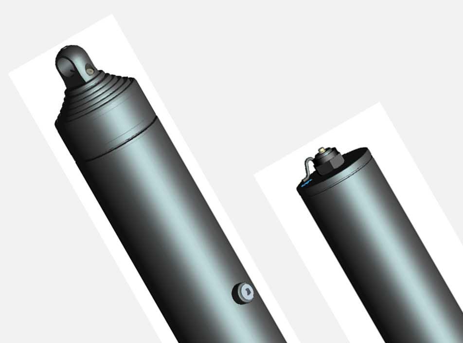
6 G-SERIES CYLINDER PARTS DESCRIPTION COVER CYLINDER PIN-TO-PIN CYLINDER Last stage Flange pin and Stover nut Plug (no bleeder) Cover lifting eye Packing seals grease zerk Last stage Mounting eye Plug (no bleeder) Welded glands Cover Base tube Moving stages Oil port SAE Spherical cover trunnion and Grease zerks assembly Welded pistons Oil port SAE Retaining rings End plates Mounting collar, bushing, circlip and grease zerks assembly Revision 0, 08/22/
7 1. CYLINDER SELECTION Telescopic cylinders are not design to be used as a structural member or to be side loads or used under abnormal usage. The cylinder is strictly a lifting device is not a structural member of the unit and cannot be used to provide stability to the dumping unit. CAUTION The hydraulic cylinder will not withstand lateral or side pressure when the unit is leaning. Cylinder must be selected with adequate analysis of the application and environment in accordance with product specifications and restrictions. Following suggestions can be follow as guidelines for proper selection and installation APPLICATION The G-SERIES telescopic cylinders are designed for dumping application such as dump truck and trailers. These type of vehicles are rollover or tilt sensitive due to external condition. Therefore, it is important to understand these working condition and design criteria prior to select and use such of cylinder ENVIRONMENT All stages of the G-SERIES telescopic cylinders are 100% salt bath nitrided which is providing good resistance against corrosion, wear and scores when stages are exposed to typical environment and working condition. Unlike chrome, this treatment does not add material to the tube surfaces which can peeloff. Instead, it treats the surface making it harder and more corrosion resistant. Additional option is available when environment becomes too aggressive such has our G4 Series for salt spreader equipment. With our best selection of seals, made of low temperature material, our G-SERIES telescopic has an intermittent recommended application temperature range of as -40 degrees F (-40 C) to +212 degrees F (100 C). Revision 0, 08/22/
8 2. CYLINDER INSTALLATION Over pressurizing the cylinder can cause severe injury or death and/or damage to cylinder and equipment CAUTION Cylinder installation should only be performed by trained and/or qualified personnel, otherwise, serious damage and/or injury is possible. Do not operate cylinder above factory maximum pressure which is typically 2,000 psi unless specified on cylinder or product datasheet. A relief valve should be used to prevent pressure peak exceeding specified maximum working pressure. An oil filer (10 micron) should be installed to keep the oil clean and contamination must not exceed the 20/18/15 class of ISO 4406 standard to prevent premature seal deterioration. The hydraulic cylinder mounted in the unit should be free to find its own trajectory line of extension, free of any lateral loading of the plungers. Misalignment of the top or bottom mountings, or mounting pins too tight, may cause scoring of the plungers, leaking, or improper sequencing which could cause the unit to upset. It is important that the cylinder is aligned correctly with the truck/trailer frame when installed. The cylinder should be exactly centered in both the vertical axis and the horizontal axis in relation with the truck/trailer frame. Vertically, the cylinder should be perpendicular (90º angle) or should tilt forward. The cylinder should be install with enough clearance along its envelope and mounting point to avoid contact with any other parts while dumping which prevent cylinder for damage or side load if body slightly move laterally while dumping. Maintain it at least 1/2" of pull out on the cylinder extension. This will prevent the cylinder from bottoming out when in the closed position. Protect packings and stages against foreign particles, welding/grinding spatter, paint and dust. Mailhot Industries Inc. recommends the use of a stroke limiter to avoid hard collisions at end of stroke. One of the most popular methods is a pump disengagement cable. This device automatically stops the pump just before the end of the cylinder stroke. Another useful device is a body stabilizer. This device allows the body to rise in a parallel axis to the truck, preventing side loading of the cylinder when the truck is on an unleveled surface or has an uneven load. The G-SERIES is a rod seal telescopic cylinder which can operate as much as 2,750 psi. Due to the fact that it is a rod seal, the effective force per stage can be calculated with the effective area (from O.D. of each stage) time the working pressure. The capacity of a dumping equipment, should be evaluate at critical point which is the less effective force at beginning of every stage stroke apply to center of gravity of both dump body and load with sufficient factor of safety. Refer to specific cylinder data sheet for dimensions, stroke, maximum working pressure and maximum trust load. Revision 0, 08/22/
9 3. GOOD USE AND OPERATION OF THE CYLINDER Do not operate the cylinder while personnel or equipment are alongside or behind the dump body or trailer. Shock pressure can cause severe injury or death and/or damage to cylinder and equipment CAUTION A cylinder should be allowed to complete its stroke without any obstacle. There should be nothing in the path of the cylinder that could interfere with its natural movement during extension and retraction. Always dump on firm and even ground. Do not operate the cylinder with a blow or a severely under inflated tire which may cause dump instability. Do not operate the cylinder when strong winds are present. These situations may cause lateral tils which can cause damage to the cylinder, misalignment of the cylinder stages and could lead to a possible rollover of the vehicle. Always dump with a tractor and trailer are align. Trailers and end-dump trailers should never be unloaded in a jack-knifed position. Never drive with a raised dump body. Stay out of the working area of an operating dump body. The operator of the equipment should always stay at the controls. If the vehicle starts to tilt, it should be lowered immediately. Always be careful not to lower the body to fast and try to lower in a steady motion. Sudden stopping or jerking can cause a sudden peak in pressure within the cylinder and could cause damage. Do not overload and load evenly. The load should be evenly distributed in the body in a horizontal and vertical manner. A load that sticks to the body increases the risk of tilting or potential rollover. The operator should lower the body to assess the situation. Never jerk the body to release a stuck load. This can cause damage to the body, hydraulic system, and the vehicle itself. It is preferable to lower the body and to use a manual or mechanical means to free the material. Do not move the truck and/or use sudden stops with the cylinder extended to free a stuck load. Never extend the trailer cylinder in the presence of high voltage electrical lines. The G-SERIES has no bleeder and is bleeding itself through the hydraulic system. After installation, or when cylinder is bouncing during operation, it is important to cycle the cylinder to full stroke 7-10 times to purge the air out of the system. It is also possible that the oil drain back to reservoir and let air coming in the system when truck is not working for a certain period of time or when connecting the tractor hydraulics to the trailer. In those cases, we recommend to cycle to full cycle 2-3 times. The following suggestions can be follow as guidelines for proper use. Revision 0, 08/22/
10 4. RECOMMENDATIONS TO PROPERLY MAINTAIN YOUR CYLINDER Worn or damaged hydraulic hoses can cause severe injury or death and/or damage to cylinder and equipment Never be under an unsupported body 4.1. DAILY INSPECTION ROUTINE IS ESSENTIAL A daily inspection routine must be a part of the safety rules and will help to detect problems. When doing your inspection routine, a visual verification is necessary to ensure the good working state of the cylinder and the hydraulic installation to avoid any breakage or leakage that could damage the cylinder or the truck: Inspect leaks at the oil tank, pump, cylinder and hoses; Ensure that all hoses and fittings are in good condition and secured out of harms way; Verify that cylinder attachments and mounting points (blocks, cradle, cover oscillating collar) are lubricated, secure and not worn. Ensure that rear hinges are lubricated, secure and without excessive wear. Ensure that cover attached to cylinder is secure and without damage. Contact your cylinder service center or manufacturer to correct damaged or loosen cover WEEKLY MAINTENANCE AND LUBRICATION Maintenance of the equipment is key to have it working to prescribed standards. Check hydraulic oil level and cleanliness according to recommendations in this guide. Oil must be compatible with hydraulic system. Never mix oil. Check tightness of all hoses and fittings. Check tightness of all bolts and nuts at mounting points (blocks, cradle and cylinder cover). Never pressure wash your cylinder. Cylinder may ingest water. Grease cylinder lubrication zerks at mounting points, blocks, cradle, cover oscillating collar and rear hinge. Do not over grease. Excessive grease may drop on stages and this should not be mistaken as packing leakage. Always use a high viscosity petroleum based grease formulated with extreme pressure, anti-wear and anticorrosion additives including molybdenum disulfide. The lubricant should include a lithium complex thickener to offer good oxidation stability, good shear stability, high temperature protection and to seal effectively against dust and resist the washing effect of water. Revision 0, 08/22/
11 A damaged cylinder installed on a vehicle can result in injuries or even death 4.3. SERVICING A CYLINDER - PRESSURISED OIL Servicing a cylinder should always be performed by qualified staffs from recommended service center from cylinder manufacturer. When the cylinder is under pressure, a small leak could allow oil to escape at high velocity causing serious injury. Avoid loose clothing, always wear safety goggles and work gloves when working around a pressured system requiring service. Great care must be taken because there is always residual pressure that remains in the cylinder. Pressure can remain in a cylinder even after it has been removed and in storage for some time. When stages are moved, even without oil supply, pressure can build up between the stages, especially if an oil port is clogged or blocked. A sudden unclogging, removal of blockage, or leak in a seal can generate enough pressure to cause serious injury CYLINDER AND HYDRAULIC SYSTEM REQUIREMENT When maintaining the cylinder or any components related to the cylinder, ensure that such components are approved for operating pressure. The maximum operating pressure of the cylinder is specified on the identification label or warning label. Cylinder always requires clean oil. The hydraulic oil contamination must not exceed the 20/18/15 class of ISO 4406 Standard to prevent seal deterioration. Hydraulic oil and filter must be replaced at least once a year. There is no bleeder on this cylinder. It is important to make sure that pump and hoses are filled with hydraulic oil prior to pressurizing the cylinder HYDRAULIC OIL To obtain optimum performances from your hydraulic installation (pump-cylinder) always use oil specifically designed to be used in hydraulic systems with a viscosity grade OF 32 cst (150 SUS) with anti-friction additives. Also, it is important to verify the chemistry of the oil to ensure that the different components and additives are compatibles with all system parts exposed to this oil HANDLING When it is time to move the cylinder for either installation, removal or storage, it is important to handle it with great care. Hard knocking of the outer wall should be considered as serious damage or should be treated as such. It is necessary to inspect the cylinder to find any scorching, scoring, leaks of different stages or any other parts that are damaged including: base tube, base attachment, bushing and circlip, zerks, stages, top attachment, and also when cover is present: flange pin, cover tube, cover nut, cover guide and cover trunnion assembly. If leaks or damage are visible and the cylinder is rendered unusable, please bring it back to the closest service center for evaluation by qualified technicians. Revision 0, 08/22/
12 4.7. RECOMMANDATIONS FOR SEAL MAINTENANCE AND PARTS REPLACEMENT Telescopic cylinders are not design to be used as a structural member or to be side loads or used under abnormal usage. Driving with a raised dump body or trailer can cause cylinder malfunction, injury or death and/or damage to equipment. Operating a damaged cylinder and cover components can cause severe injury or death and/or damage to equipment Replace seals at the earliest of either: Every 4 years; According to usage at every 10,000 cycles. Stages, cover and its connecting flange pin and stover nut are highly stressed components due to environment, application and usage. Unappropriated use may cause cylinder malfunction or failure. Lateral oscillation of the dump body during a cycle must be avoid. Lateral oscillation of dump body of trailer may occur when lowering dump body with truck in movement, or other irregular situation, and may cause leakage, excessive wear and fatigue of component and connecting members. In the case of leakage cylinder due to damaged stage, parts must be inspected and replace as necessary. In the case of excessive wear, unexpected cylinder looseness or broken external of internal component, cylinder must no be used and immediately repair with appropriate parts and methods SUGGESTIONS FOR CYLINDER REPLACEMENT As a good practice and in a preventive effort to maintain the adequate operational maintenance and security performance, it is suggested to replace the cylinder after 10 years of normal use. It is also suggested to replace the cylinder if a more intense use reaches an estimated 25,000 cycles. Revision 0, 08/22/
13 4.9. STORAGE OF CYLINDER If the cylinder must be stored, it should be protected from bad weather, direct sunlight and extreme temperature variations. Oil ports must be sealed with adapted plugs to avoid dust, water, humidity or any other contaminant to enter into the cylinder. Depending on the length of time spent in storage, some supplemental precautions should be taken. These precautions are showed below; A- For a 6 months storage or less, no special precautions others then those stated above. B- For a storage period between 6 months and less than 12 months, cylinders should be stored vertically. C- If storage period is more the 12 months and less than 24 months, a pressure test must be done to ensure the good state of seals prior to utilisation. D- After a storage period of more than 24 months, all seals must be replaced. If storage facilities are open or non-existent, the cylinder should at least be stored vertically and filled with oil. Revision 0, 08/22/
14 TROUBLESHOOTING PROBLEMS PROBABLE CAUSES SOLUTIONS Cylinder does not Safety or control valves are stuck or Clean or replace the valves extend broken Cylinder extend too slow Cylinder extend too fast Cylinder is bouncing or jerks during operation Cylinder opens or closes without a smooth operation PTO or pump not engaged or broken Cylinder too small Air trapped in cylinder or system or Not enough oil Oil tank too small Oil viscosity is too high or oil too cold Air trapped in cylinder or system or Not enough oil Pump or valve worn-out Pump is running too slow. Pump is too small or PTO speed is too slow Pump is running too high. Pump is too large or PTO speed is too high Air trapped in cylinder or hydraulic system. Internal parts of the cylinder are too worn-out One of the stage or gland is swelling or not sliding smoothly. Engage PTO or Change broken parts Consult body/trailer manufacturer. Select cylinder adequately. Check for infiltration and correct. Check oil level and correct. Cycle cylinder to full extension 7 to 10 times. Consult body/trailer manufacturer. Oil tank may be increase according to cylinder capacity. Warm up oil Use oil according to cylinder and system specification Check for infiltration and correct. Check oil level and correct. Cycle cylinder to full extension 7 to 10 times. Change worn-out parts Increase engine speed Check cylinder, pump, PTO specification. Change pump or PTO accordingly. Reduce engine speed Check cylinder, pump, PTO specification. Change pump or PTO accordingly. Cycle cylinder to full stroke 7 to 10 times. Service or replace cylinder. Verify and replace worn-out parts. Revision 0, 08/22/
15 TROUBLESHOOTING PROBLEMS PROBABLE CAUSES SOLUTIONS Cylinder stages are bend or bulged due to side load, misalignment, or over pressurisation. Cylinder does not retract. One or more stages of the cylinder stays open. Cylinder is too fast. As a result, plungers and gland are jamming. Check for any misalignment of the cylinder with frame or back hinge, and correct. Check safety valve setting. Service or replace cylinder See Troubleshooting / cylinder extend too fast. Cylinder retract too slow Cylinder retract too fast Dumping angle to high Valve or hoses too small Oil viscosity is too high or oil too cold Material stuck in bed dumping angle too low. Consult body/trailer manufacturer. Stroke may need to be decrease. Install a limiting device Consult body/trailer manufacturer. Valve and return line may need to be increase. Warm up oil Use oil according to cylinder and system specification Consult body/trailer manufacturer. stroke may need to be increase. Cylinder too small, body/trailer too heavy, Valve or hoses too large. Cylinder is leaking oil Seals are worn due to high cylinder speed. Seals are worn or stages are score due to oil contamination. Seals are worn or stages are scored due to sideload or missalignment of the cylinder. Consult body/trailer manufacturer. Select parts adequately. Troubleshooting / cylinder extend too fast or cylinder retract too slow. Check oil cleanliness, replace as necessary. Verify and correct alignment. Change worn-out parts. Cover guide in contact with moving stages during operation Noisy cylinder or cover Grease drop on stages. Cylinder is side loaded due to misalignment or incorrect use. Loosen or damaged cylinder, flange pin, lock nut or cover parts. Bent or bulged moving stage. Loosen or damaged cylinder, Oil leakage may be mistaken. Rag stage and excessive grease. Check for any misalignment of the cylinder with frame or back hinge, and correct. Fully read and understand this user guide for cylinder usage. Service or replace cylinder Check for any misalignment of the cylinder with frame or back hinge, and correct. Service or replace cylinder Revision 0, 08/22/
Instruction Sheet 1.0 IMPORTANT RECEIVING INSTRUCTIONS 2.0 SAFETY. 2.1 Introduction. 2.2 Hydraulic Cylinder Safety Precautions (RT-Series)
") Instruction Sheet POWERFUL SOLUTIONS. GLOBAL FORCE. L4211 Rev. A 09/17 RT-Series Multi-Stage Telescopic Hydraulic Cylinders Table of Contents Page 1.0 IMPORTANT RECEIVING INSTRUCTIONS... 1 2.0 SAFETY...
Instruction Sheet POWERFUL SOLUTIONS. GLOBAL FORCE. L4211 Rev. A 09/17 RT-Series Multi-Stage Telescopic Hydraulic Cylinders Table of Contents Page 1.0 IMPORTANT RECEIVING INSTRUCTIONS... 1 2.0 SAFETY...
Installation and Service Manual
 An Actuant Company Installation and Service Manual Heavy Duty Hydraulic Stabilization Legs CONTENTS Part # 3010003129 REV 0D Section Page 1.0 Receiving Instructions 2 2.0 Safety Issues 2 3.0 Hydraulic
DBML-60/80 Squeeze Tool
 DBML-60/80 Squeeze Tool OPERATORS MANUAL Description The Mustang Model DBML-60/80 Hydraulic squeeze tool has been manufactured since 1995. A Mustang 3 3/4 bore doubleacting cylinder producing 41,000 lbs
REV0709. Parts List. Hydraulic Cylinder Model MODEL C SINGLE-ACTING, SPRING RETURN HYDRAULIC CYLINDER. Max. Capacity: 55.2 Tons at 10,000 PSI
 REV0709 Parts List Hydraulic Cylinder Model 10312 MODEL C SINGLE-ACTING, SPRING RETURN HYDRAULIC CYLINDER Max. Capacity: 55.2 Tons at 10,000 PSI REV0709 Item No. Part No. No. Req d Description 1 10606
MODEL 840 AIR HYDRAULIC PUMP INSTRUCTION
 MODEL 840 AIR HYDRAULIC PUMP INSTRUCTION Jackco Transnational Inc. 202 South El Monte, CA 888-452-2526 www.jackco.com FOR YOUR SAFETY Read all instructions, warnings and cautions carefully. Follow all
Model 7989T Steel Pipe Squeezer Sch. 40 & Sch. 80. Operations Manual
 10-12 Steel Pipe Squeezer Sch. 40 & Sch. 80 Operations Manual 1.0 Introduction This manual is issued as a basic operation manual covering the Regent Model 7989T, Pipe Squeezer and Pump as manufactured
INSTRUCTION AND PARTS MANUAL MODELS #13000 TO HYDRAULIC CYLINDERS
 INSTRUCTION AND PARTS MANUAL MODELS #13000 TO 13080 HYDRAULIC CYLINDERS Form No. 102397-AME Operating Instructions for: Single-acting and Double-acting Rams and Cylinders (Various Capacity) DEFINITIONS
1.0 - OPENING AND CLOSING THE DOOR
 The purpose of this manual is to provide the user with instructions on how to safely open and close, how to conduct routine maintenance, and how to install the PEI TWINLOCK Closure on a pressure vessel.
AIR COMPRESSOR OPERATING INSTRUCTION AND PARTS LIST
 AIR COMPRESSOR OPERATING INSTRUCTION AND PARTS LIST OIL-LESS TYPE IMPORTANT: PLEASE READ CAREFULLY BEFORE STARTING OPERATIONS. THE CONTENTS ARE FOR GENERAL INFORMATION OF ALL THE SIMILAR MODELS. Record
This section provides general information and recommendations required prior to installing, operating or maintaining your KAT Master Hitch.
 WBM Parts and Installation Manual for KAT Master Hitch General Information This section provides general information and recommendations required prior to installing, operating or maintaining your KAT
HPB25 Hydraulic Paving Breaker
 INSTRUCTION MANUAL HPB25 Hydraulic Paving Breaker Read and understand all of the instructions and safety information in this manual before operating or servicing this tool. Register this product at www.greenlee.com
INSTALLATION, OPERATION AND MAINTENANCE GUIDE
 INSTALLATION, OPERATION AND Placement in Pipeline System When installing Process Development & Control s ElastoTITE Elastomer-Hinged Check Valves in a pipeline, a minimum of five pipe diameters should
JACK MODULE HYDRAULIC CYLINDERS
 Form No. 102901 Operating Instructions for: JM SERIES High Tonnage Portable Jacks JACK MODULE HYDRAULIC CYLINDERS All cylinders are marked with maximum pressure setting NOTE: For a detailed parts list
HYDRAULIC INTENSIFIER Max. Pressure: See Intensifier Data Plate Weight: 16 Lbs. (7.26 kg)
") Form No. 102897 Operating Instructions for: HB443 HB444 HYDRAULIC INTENSIFIER Max. Pressure: See Intensifier Data Plate Weight: 16 Lbs. (7.26 kg) Definition: A devise that raises the inlet pressure to
Form No. 102897 Operating Instructions for: HB443 HB444 HYDRAULIC INTENSIFIER Max. Pressure: See Intensifier Data Plate Weight: 16 Lbs. (7.26 kg) Definition: A devise that raises the inlet pressure to
Instruction Manual. Maximum Operating Pressure 1,500 bar
 Hydraulic Bolt Tensioners Model DBT Series Maximum Operating Pressure 1,500 bar ABSOLUTE EQUIPMENT PTY LTD 2/186 Granite Street, GEEBUNG QLD 4034 Australia sales@absoluteequipment.com.au Phone: +61 7 3865
Hydraulic Punch Drivers
 SERVICE MANUAL 7804SB / 7806SB Quick Draw 7704SB / 7706SB Quick Draw Flex Quick Draw Hydraulic Punch Drivers Serial Codes AHJ and YZ Read and understand all of the instructions and safety information in
20 Ton SD Shop Press Operating Instructions
 20 Ton SD Shop Press Operating Instructions MODEL NO. 850SD Hazard Symbols Used in the Manuals This manual includes the hazard symbols defined below when the operations or maintenance job involves a potential
42045 Heavy Duty ADA Base Model Kit: 85/105 PSI (ADA Compressor Only) Heavy Duty ADA Base Model Kit: 110/145 PSI (ADA Compressor Only)
 Heavy Duty ADA Base Model Kit: 110/145 PSI (ADA Compressor Only)") 42045 Heavy Duty ADA Base Model Kit: 85/105 PSI (ADA Compressor Only) 42047 Heavy Duty ADA Base Model Kit: 110/145 PSI (ADA Compressor Only) 45052 Constant Duty ADA Base Model Kit: 85/105 PSI (ADA Compressor
42045 Heavy Duty ADA Base Model Kit: 85/105 PSI (ADA Compressor Only) 42047 Heavy Duty ADA Base Model Kit: 110/145 PSI (ADA Compressor Only) 45052 Constant Duty ADA Base Model Kit: 85/105 PSI (ADA Compressor
COMMON PRECAUTIONS Data Sheet - Be Sure To Read Before Handling Page 1 of 6
 COMMON PRECAUTIONS Page 1 of 6 These safety instructions are intended to prevent a hazardous situation and/or equipment damage. These instructions indicate the level of potential hazard by labels of "Caution",
Allspeeds Ltd. Royal Works, Atlas St Clayton le Moors Accrington Lancashire England BB5 5LW. Tel +44 (0)
") Allspeeds Ltd. Royal Works, Atlas St Clayton le Moors Accrington Lancashire England BB5 5LW Tel +44 (0)1254 615100 www.allspeeds.co.uk SOFTLINE CUTTER SL80 PRODUCT CODE No. 980248 INSTRUCTIONS FOR INSTALLATION,
Allspeeds Ltd. Royal Works, Atlas St Clayton le Moors Accrington Lancashire England BB5 5LW Tel +44 (0)1254 615100 www.allspeeds.co.uk SOFTLINE CUTTER SL80 PRODUCT CODE No. 980248 INSTRUCTIONS FOR INSTALLATION,
INSTALLATION, OPERATION AND SERVICE MANUAL ABS AIR BAG LIFT
 INSTALLATION, OPERATION AND SERVICE MANUAL ABS AIR BAG LIFT P.O. Box 1058 1058 West Industrial Avenue Guthrie, OK 73044-1058 405-282-5200 FAX: 405-282-8105 www.autoquip.com Item # 830ABS Version 1.0 07/2001
Installation, Operation and Maintenance Manual for Back Pressure Regulator
 Installation, Operation and Maintenance Manual for Back Pressure Regulator Model 8860 2009 Groth Corporation IOM-8860 Rev. B 12541 Ref. ID: 95565 Page 2 of 13 Table of Contents I. INTRODUCTION 3 II. DESIGN
444C DUAL PERFORMANCE VALUE PACK
 (Chrome) PART NO. 44432 IMPORTANT: It is essential that you and any other operator of this product read and understand the contents of this manual before installing and using this product. SAVE THIS MANUAL
PDY TON HYDRAULIC CRIMPING TOOL WARNING
 OPERATORS ORS GUIDE PDY-1220 12 TON HYDRAULIC CRIMPING TOOL All information found in this guide must be read and understood before use or testing of this tool. Failure to read and understand these warnings
MODEL 200 KNIFE GATE VALVES INSTALLATION & MAINTENANCE MANUAL
 MODEL 200 KNIFE GATE VALVES INSTALLATION & MAINTENANCE MANUAL Index 1. List of components / General arrangement 2. Description 3. Handling 4. Installation 5. Actuators / Operation 6. Maintenance a. Changing
450P- RV AUTOMATIC PORTABLE COMPRESSOR EXTREME SERIES
 450P- RV AUTOMATIC PORTABLE COMPRESSOR EXTREME SERIES PART NO. 45053 IMPORTANT: It is essential that you and any other operator of this product read and understand the contents of this manual before installing
75 Ton SD Shop Press Operating Instructions
 75 Ton SD Shop Press Operating Instructions MODEL NO. 856SD Hazard Symbols Used in the Manuals This manual includes the hazard symbols defined below when the operations or maintenance job involves a potential
Operation and Maintenance Instructions
 Hydratight Limited Bentley Road South Darlaston West Midlands WS10 8LQ United Kingdom Tel: +44 121 50 50 600 Fax: +44 121 50 50 800 E-mail: enquiry@hydratight.com Website: www.hydratight.com TOP COLLAR
Wafer Check Valve. Contents. User s Manual. (1) Be sure to read the following description of our product warranty 1
 Be sure to read the following description of our product warranty 1") Serial No. H-V066-E-3 Wafer Check Valve User s Manual Contents (1) Be sure to read the following description of our product warranty 1 (2) General operating instructions 2 (3) General instructions for
Serial No. H-V066-E-3 Wafer Check Valve User s Manual Contents (1) Be sure to read the following description of our product warranty 1 (2) General operating instructions 2 (3) General instructions for
BUTTERFLY VALVES Series 800
 BUTTERFLY VALVES Series 800 WARNING Before proceeding read ALL instructions and become familiar with the equipment and associated drawings. Follow ALL applicable safety regulations and codes for pressurized
MUELLER. Mega-Lite Drilling Machine. Reliable Connections. table of contents PAGE. Equipment 2. Operating Instructions 3-4. Parts Information 5
 operating Instructions manual MUELLER Mega-Lite Drilling Machine table of contents PAGE Equipment 2 Operating Instructions 3-4 Parts Information 5 Travel Charts 6-11! WARNING: 1. Read and follow instructions
GAS STRUT SAFETY INFORMATION
 VERSION 4.0 - PAGE 1 CONTENTS 1. SAFETY REQUIREMENTS 2. INSTALLATION 3. DO S AND DON TS 4. PERIODIC INSPECTION 5. SERVICE LIFE 6. FUNCTIONAL SAFETY 7. DAMAGED GAS STRUTS VERSION 4.0 - PAGE 2 SAFETY REQUIREMENTS
Operation Manual Guillotine Cutter RC-5
 Operation Manual Guillotine Cutter RC-5 Technical Specifications General Safety/Operating Instructions Using the Guillotine Cutter/Crimper Blade Change Instructions Maintenance Instructions This is a detailed
Needle valve. Contents. User s Manual. (1) Be sure to read the following warranty clauses of our product 1. (2) General operating instructions 2
 Be sure to read the following warranty clauses of our product 1. (2) General operating instructions 2") Serial No. H-V024-E-7 Needle valve User s Manual Contents (1) Be sure to read the following warranty clauses of our product 1 (2) General operating instructions 2 (3) General instructions for transportation,
Serial No. H-V024-E-7 Needle valve User s Manual Contents (1) Be sure to read the following warranty clauses of our product 1 (2) General operating instructions 2 (3) General instructions for transportation,
35 TON HYDRAULIC PUNCH WARNING
 OPERATORS GUIDE REL-35T-PNC 35 TON HYDRAULIC PUNCH NOTICE Sizes, weights and tool specifications listed in this manual are subject to change without notice. Please consult factory for information and updates.
Copyright, 2005 GPM Hydraulic Consulting, Inc.
 Troubleshooting and Preventive Maintenance of Hydraulic Systems Learning to Read the Signs of Future System Failures Instructed by: Al Smiley & Alan Dellinger Copyright, 2005 GPM Hydraulic Consulting,
400C & 450C DUAL PERFORMANCE VALUE PACKS
 (Chrome) PART NO. 40013 (Silver) PART NO. 45012 (Chrome) PART NO. 45013 IMPORTANT: It is essential that you and any other operator of this product read and understand the contents of this manual before
OPERATING INSTRUCTIONS. Parts List N. Note: Owner and operator MUST read and understand this operating instructions before use this lift table.
 OPERATING INSTRUCTIONS Parts List 770N te: Owner and operator MUST read and understand this operating instructions before use this lift table. Thank you for using this lift table. Your lift table is made
30T A/Manual Hydraulic Shop Press
 30T A/Manual Hydraulic Shop Press Operation Manual 1 1. Important Information 1.1 Safety Information 1.1.1 Hazard Symbols Used in the Manuals This manual includes the hazard symbols defined below when
REL-46 WARNING NOTICE 15 TON SINGLE ACTING REMOTE HYDRAULIC CRIMPING HEAD. Compatible with RELIABLE R15 and P Style dies. REL-46 Manual
 OPERATORS ORS GUIDE REL-46 15 TON SINGLE ACTING REMOTE HYDRAULIC CRIMPING HEAD Compatible with RELIABLE R15 and P Style dies. RELIABLE EQUIPMENT & SERVICE CO., INC. 301 Ivyland Road Warminster, PA 18974
Pressure Relief Valve Instruction Manual
 CVR3-M0_062017 Pressure Relief Valve Instruction Manual MODEL: CVR3 SFA Companies 10939 N. Pomona Ave. Kansas City, MO 64153 Tel: 888-332-6419 * Fax: 816-448-2142 E-mail: sales@bvahydraulics.com Website:
200 PSI FAST-FILL AIR SOURCE KIT
 200 PSI FAST-FILL AIR SOURCE KIT 55% Duty Compressor on 2.0 Gallon Air Tank PART NO. 20007 IMPORTANT: It is essential that you and any other operator of this product read and understand the contents of
200 PSI HIGH-FLOW AIR SOURCE KIT
 200 PSI HIGH-FLOW AIR SOURCE KIT 50% Duty Compressor on 2.0 Gallon Air Tank PART NO. 20008 IMPORTANT: It is essential that you and any other operator of this product read and understand the contents of
ACCUMULATOR OPERATING & MAINTENANCE INSTRUCTIONS
 ACCUMULATOR OPERATING & MAINTENANCE INSTRUCTIONS READ ALL INSTRUCTIONS PRIOR TO INSTALLATION AND OPERATION TO AVOID POSSIBLE INJURY Warning: Always consider any accumulator to contain pressure until proven
Bray/ VAAS O-Ported Series Knife Gate Valve 770/780 Series Operation and Maintenance Manual
 Bray/ VAAS Knife Gate Valve 770/780 Series Operations and Maintenance Manual Table of Contents Definition of Terms 1 Safety Instructions 1 Introduction 2 Unpacking 2 Storage 2 Installation 2 Commissioning
MODEL SWH10 1,000 LB CAPACITY SWIVEL HOIST
 MODEL SWH10 1,000 LB CAPACITY SWIVEL HOIST PARTS BREAKDOWN AND OPERATING MANUAL Copyright 2007, Arcan Professional Tools Rev: 05/15/07 This operating manual contains important safety information. Read
OPERATIONS MANUAL IMPORTANT SAFETY INFORMATION
 OPERATIONS MANUAL IMPORTANT SAFETY INFORMATION Please read, understand and follow all safety information contained in these instructions prior to the use of this tool. Retain these instructions for further
Operator s Manual. with Maintenance Schedule. Fourth Edition Second Printing Part No
 Operator s Manual with Maintenance Schedule Fourth Edition Second Printing Part No. 82297 Operator s Manual Fourth Edition Second Printing Important Read, understand and obey these safety rules and operating
AIR/OVER HYDRAULIC JACK 20 TON
 AIR/OVER HYDRAULIC JACK 0 TON 4487 ASSEMBLY AND OPERATING INSTRUCTIONS 349 Mission Oaks Blvd., Camarillo, CA 930 Visit our Web site at http://www.harborfreight.com Copyright 999 by Harbor Freight Tools.
450P AUTOMATIC PORTABLE COMPRESSOR EXTREME SERIES
 EXTREME SERIES PART NO. 45043 IMPORTANT: It is essential that you and any other operator of this product read and understand the contents of this manual before installing and using this product. SAVE THIS
FIREFIGHTING EQUIPMENT
 FIREFIGHTING EQUIPMENT User Manual ANTENOR 3000 Base or portable Trailer DOC 1974 En Rev.B - 22/10/13 Tel : 03 25 39 84 78 - Fax : 03 25 39 84 90 - Email : france@pok.fr - Web : www.pok.fr Identification
97C COMPRESSOR KIT 12V PART NO C COMPRESSOR KIT 24V PART NO C COMPRESSOR KIT PART NO
 97C COMPRESSOR KIT 12V PART NO. 00097 97C COMPRESSOR KIT 24V PART NO. 02497 98C COMPRESSOR KIT PART NO. 00098 97C 98C IMPORTANT: It is essential that you and any other operator of this product read and
Manual Actuated Boiler Blowdown Valves
 Manual Actuated Boiler Blowdown Valves Installation and Maintenance Instructions 1. Safety information 2. General product information 3. Installation 4. Operation 5. Maintenance 6. Spare parts p.1 1. Safety
HYDRAULIC CYLINDER FOR USE WTH:- HVL, HPS, HLS, HSS, HAS, HHS, HHR, HDA & HGS
 INSPECTION UPON RECEIPT OF GOODS On initial receipt of goods visually check for transit damage. If found contact the carrier immediately. Hi-Force does not necessarily know the circumstances of use of
CONTENTS: 57100AH 100 Ton Air/Hydraulic Shop Press OWNER'S MANUAL
 OWNER'S MANUAL CONTENTS: Page 1 Warning Information 2 Specifications, Operating Instructions and Notes 3 Inspection, Safety Instructions and Limited Warranty 4 Parts Diagram PRESS SPECIFICATIONS Sunex
HYDRAULIC MOBILE LIFTING TABLE
 HYDRAULIC MOBILE LIFTING TABLE MODEL NO: HTL300 & HTL500 PART NO: 7610148 & 76210152 OPERATION & MAINTENANCE INSTRUCTIONS ORIGINAL INSTRUCTIONS GC1116 INTRODUCTION Thank you for purchasing this CLARKE
Index Table. Model 794. Installation, Operating and Maintenance Instructions
 CLOCKWISE MANUAL MAKING INTO CCW TABLE Index Table Model 794 Installation, Operating and Maintenance Instructions Black & Webster Products Division 545 Hupp Ave. P.O. Box 831, Jackson, Michigan 49204 2009
RhinoPro Cartridge Gun Manual
 RhinoPro Cartridge Gun Manual RhinoPro Cartridge Gun 1500 with 750ml cartridges Table of Contents Application Instructions......................................... 1 Operating Instructions..........................................
Allspeeds Ltd. Royal Works, Atlas St Clayton le Moors Accrington Lancashire England BB5 5LW. Tel +44 (0)
") Allspeeds Ltd. Royal Works, Atlas St Clayton le Moors Accrington Lancashire England BB5 5LW Tel +44 (0)1254 615100 www.allspeeds.co.uk SOFT LINE CUTTER SL55 PRODUCT CODE No. 980504 INSTRUCTIONS FOR INSTALLATION,
Allspeeds Ltd. Royal Works, Atlas St Clayton le Moors Accrington Lancashire England BB5 5LW Tel +44 (0)1254 615100 www.allspeeds.co.uk SOFT LINE CUTTER SL55 PRODUCT CODE No. 980504 INSTRUCTIONS FOR INSTALLATION,
Q-POWER 106 SERIES HYDRAULIC SQUEEZE CHUTE PRODUCT MANUAL arrowquip.com
 Q-POWER 106 SERIES HYDRAULIC SQUEEZE CHUTE PRODUCT MANUAL 1-877-275-6075 cs@arrowquip.com arrowquip.com CONTENTS General Description of the Q-Power 106 Series Hydraulic 1 Squeeze Chute Safety Precautions
REL-510H WARNING NOTICE 12 TON SINGLE ACTING REMOTE HYDRAULIC CRIMPING HEAD
 OPERATORS ORS GUIDE REL-510H 12 TON SINGLE ACTING REMOTE HYDRAULIC CRIMPING HEAD Compatible with U style and RELIABLE R12 shell type 12 ton compression dies. RELIABLE EQUIPMENT & SERVICE CO., INC. 92 Steamwhistle
SAILTEC, INC CONGER COURT, OSHKOSH, WI USA
 OK to make this valve hand tight. Pin Mount Style Integral lies 4-5 Degrees above Horizontal. If you store your Hunter "bow down" you will get air-lock in the Integral. Slot Mount Style Pump Body "Down"
4 IN. BALL LAUNCHER Engine Mounted / PTO Driven
 4 IN. BALL LAUNCHER Engine Mounted / PTO Driven OPERATOR S PARTS and MAINTENANCE MANUAL 2006 EDITION BL-MAN-4EN Creation Revision date: 10MAR06 date: by: Ivon LeBlanc by: Table of Contents Table of Contents...
DK ton, Double-acting, Die-type Crimping Tool
 INSTRUCTION MANUAL DK6040 60-ton, Double-acting, Die-type Crimping Tool Read and understand all of the instructions and safety information in this manual before operating or servicing this tool. Register
Cylinder Tilt Saddle Instruction Manual
 Cylinder Tilt Saddle Instruction Manual MODELS: SDT05, SDT10, SDT15, SDT25 SFA Companies 10939 N. Pomona Ave. Kansas City, MO 64153 Tel: 888-332-6419 - Fax: 816-448-2142 E-mail: sales@bvahydraulics.com
Installation & Operation Manual Proven Quality since 1892
 Content 1. ERIKS operating companies 2. Product description 3. Requirements for maintenance staff 4. Transport and storage 5. Function 6. Application 7. Installation 8. Maintenance 9. Service and repair
RARS5000 AIR BODY SAW OWNER S OPERATING MANUAL
 RARS5000 AIR BODY SAW OWNER S OPERATING MANUAL DESCRIPTION 1. No mar 2. No mar tip 3. Housing grip 4. Trigger 5. Air inlet 6. Air inlet plug 7. Plastic board Important! It is essential that you read the
SERVICE INSTRUCTIONS PVWJ A-FRAME PUMPS -011/-014/-022 FOR TYPE P-1NN AND P-LNN PRESSURE COMPENSATING CONTROLS
 Bulletin 947633 SERVICE INSTRUCTIONS PVWJ A-FRAME PUMPS -011/-014/-022 FOR TYPE P-1NN AND P-LNN PRESSURE COMPENSATING CONTROLS OILG0250 PURPOSE OF INSTRUCTIONS Figure 1. Typical Oilgear Type P-1NN and
Installation, Operation & Maintenance Manual for Flo-Max Coupler Bracket Model FM150
 Installation, Operation & Maintenance Manual for Flo-Max Coupler Bracket Model FM150 January 2013 Form FVC 084 - Rev 02 IMPORTANT: KEEP THIS DOCUMENT WITH THE PRODUCT UNTIL IT REACHES THE END USER. 1.
1. SAFETY 2. PREPARATION 3. FRAME 4. TRANSMISSION 5. DRIVE 6. ROW UNIT 7. OPTIONAL EQUIPMENT
 TABLE OF CONTENTS 1. SAFETY 2. PREPARATION 3. FRAME 4. TRANSMISSION 5. DRIVE 6. ROW UNIT 7. OPTIONAL EQUIPMENT This symbol means: ATTENTION - BECOME ALERT YOUR SAFETY IS INVOLVED. When you see this symbol
Hydraulic Punch Drivers
 INSTRUCTION MANUAL 7804SB / 7806SB Quick Draw 7704SB / 7706SB Quick Draw Flex 7904SB / 7906SB Quick Draw 90 Quick Draw Hydraulic Punch Drivers Serial Codes AHJ, YZ, and ZA Read and understand all of the
200 PSI COMPRESSORS - MODEL NUMBERS
 200 PSI COMPRESSORS - MODEL NUMBERS 380C AIR COMPRESSOR KIT PART NO. 38033 480C AIR COMPRESSOR KIT PART NO. 48043 380C 480C IMPORTANT: It is essential that you and any other operator of this product read
WBM Installation Manual KAT Master Hitch
 WBM Installation Manual KAT Master Hitch General Information This section provides general information and recommendations required prior to installing, operating or maintaining your KAT Master Hitch.
Apollo Standard Port, Full Port & One Piece Flanged Ball Valves Installation, Operation, & Maintenance Manual
 I854000.D Apollo Standard Port, Full Port & One Piece Flanged Ball Valves Installation, Operation, & Maintenance Manual Introduction This manual presents guidelines for the Installation, Operation and
LP6 Hydraulic Crimping Tool
 INSTRUCTION MANUAL LP6 Hydraulic Crimping Tool Serial Codes GMA, GMB, GMD, and GME Read and understand all of the instructions and safety information in this manual before operating or servicing this tool.
SERVICE INSTRUCTIONS PVWJ A-FRAME PUMPS -011/-014/-022 FOR TYPE P-C AND P-K SOFT START PRESSURE COMPENSATING CONTROLS
 Bulletin 947639 SERVICE INSTRUCTIONS PVWJ A-FRAME PUMPS -011/-014/-022 FOR TYPE P-C AND P-K SOFT START PRESSURE COMPENSATING CONTROLS OILG0260 Figure 1. Typical Oilgear Type P-C and P-K Soft Start Controls
SERVICE INSTRUCTIONS P-A OR P-B ELECTRONIC PRESSURE COMPENSATOR, SERIES F1U CONTROLS
 Bulletin 947556 SERVICE INSTRUCTIONS P-A OR P-B ELECTRONIC PRESSURE COMPENSATOR, SERIES F1U CONTROLS OILG0390 Figure 1. Typical Oilgear Type P-A or P-B Electronic Pressure Compensator, Series F1U Controls
MODEL NUMBER: P-A AUTOMATIC PORTABLE COMPRESSOR
 MODEL NUMBER: 45043-450P-A AUTOMATIC PORTABLE COMPRESSOR IMPORTANT: It is essential that you and any other operator of the product read and understand the contents of this manual before installing and
accidents which arise due to non-observance of these instructions and the safety information herein. SPECIFICATIONS
 18 GAUGE 1-1/4 INCH BRAD NAILER Model: 7611 CALIFORNIA PROPOSITION 65 WARNING: You can create dust when you cut, sand, drill or grind materials such as wood, paint, metal, concrete, cement, or other masonry.
MODEL NUMBER: PSI AIR SOURCE KIT 200 PSI Compressor on 2.0 Gallon 200 PSI Air Tank
 IMPORTANT SAFETY INSTRUCTIONS CAUTION - To reduce risk of electrical shock or Electrocution: MODEL NUMBER: 20008 200 PSI AIR SOURCE KIT 200 PSI Compressor on 2.0 Gallon 200 PSI Air Tank IMPORTANT: It is
Roller Chain and Sprocket Troubleshooting Guide
 Roller Chain and Sprocket Troubleshooting Guide Drive System (Roller Chain and Sprockets) Troubleshooting Guide 1. General Chain is riding up on the sprocket. The roller chain and sprocket do not match.
TriPod Safety Coupler Installation & Operating Instructions for Models TP4, TP5, TP6, and TP7
 TriPod Safety Coupler Installation & Operating Instructions for Models TP4, TP5, TP6, and TP7 March 2014 Form FVC097 - Rev03 IMPORTANT: KEEP THIS DOCUMENT WITH THE PRODUCT UNTIL IT REACHES THE END USER.
Tech Tips. Service Call: Adjustable Hydraulic Valves Flow controls Pressure controls Sequence valves Holding valves
 Service Call: Adjustable Hydraulic Valves Flow controls Pressure controls Sequence valves Holding valves Tools Required: Flow Meter Pressure gauge Holding valve test block Wrenches for installation of
OPERATIONS MANUAL RIGHT ANGLE CAPSTAN
 OPERATIONS MANUAL RIGHT ANGLE CAPSTAN TABLE OF CONTENTS Patterson Heritage... 3 ISO 9001 Certification and Affiliates... 4 Warranty and Return Policy... 5 Important Operations Manual Instructions, Basic
MODEL NUMBER: M20005 AIR SOURCE KIT. 30% Duty Compressor on. 2.0 Gallon Air Tank SAVE THIS MANUAL FOR FUTURE REFERENCE
 MODEL NUMBER: M20005 AIR SOURCE KIT 30% Duty Compressor on 2.0 Gallon Air Tank SAVE THIS MANUAL FOR FUTURE REFERENCE USER MANUAL IMPORTANT SAFETY INSTRUCTIONS CAUTION - To reduce risk of electrical shock
APCO ARV CLEAN WATER AIR RELEASE VALVES. Model 50A
 APCO ARV CLEAN WATER AIR RELEASE VALVES Model 50A Instruction D12013 February 2017 Instructions These instructions provide installation, operation and maintenance information for APCO ARV Clean Water Air
100C Air Compressor Kit
 10010 100C Air Compressor (standard mounting bracket, CE Spec) 10014 100C Air Compressor (no leader hose or check valve, CE Spec) 10016 100C Air Compressor (with Omega Bracket, CE Spec) IMPORTANT: It is
IMPORTANT SAFETY INSTRUCTIONS
 IMPORTANT SAFETY INSTRUCTIONS CAUTION - To reduce risk of electrical shock: - Do not disassemble. Do not attempt repairs or modifications. Refer to qualified service agencies for all service and repairs.
WARNING. RELIABLE EQUIPMENT & SERVICE CO., INC. 301 Ivyland Road Warminster, PA USA Phone: Fax:
 OPERATOR'S GUIDE Pivot style control valves may be operated with one hand, leaving the second hand free to control the head. Lever locks in the forward position for tool advance, and in the rear position
Roto-Max Work Positioner. Operation. Maintenance
 Roto-Max Work Positioner Operation Maintenance Lift Products Inc. P.O Box 349 Elm Grove Wisconsin 53122-0349 PH: 877-543-8776 FX: 262-521-5725 Manual #19950 1 WARNING Do not operated this lift table unless
INSTALLATION, MAINTENANCE & OPERATING INSTRUCTIONS 2-4 REDUCED PORT/ FULL PORT (5700/6700) ANSI CLASS 150/300/600/900/1500/2500 TRUNNION BALL VALVES
 ANSI CLASS 150/300/600/900/1500/2500 TRUNNION BALL VALVES") PBV-USA,Inc. 12735 Dairy Ashford. Stafford, Texas USA 77477 281-340-5400; 800-256-6193 FAX: 281-340-5499 INDUSTRIAL BALL VALVES IM0 69 April 2001 Rev 9 INSTALLATION, MAINTENANCE & OPERATING INSTRUCTIONS
PBV-USA,Inc. 12735 Dairy Ashford. Stafford, Texas USA 77477 281-340-5400; 800-256-6193 FAX: 281-340-5499 INDUSTRIAL BALL VALVES IM0 69 April 2001 Rev 9 INSTALLATION, MAINTENANCE & OPERATING INSTRUCTIONS
accidents which arise due to non-observance of these instructions and the safety information herein. SPECIFICATIONS
 18 GAUGE 2 INCH BRAD NAILER Model: 7555 CALIFORNIA PROPOSITION 65 WARNING: You can create dust when you cut, sand, drill or grind materials such as wood, paint, metal, concrete, cement, or other masonry.
MAINTENANCE RECOMMENDATIONS
 MAINTENANCE RECOMMENDATIONS COOLING SYSTEM: Very high secondary currents are developed in resistance welding equipment. This, coupled with compact design, high upset temperatures, and fast cycle times,
Instruction sheet for Hydraulic Cylinder
 Oper at or smanual 1088710891 Hydr aul i ccyl i nder s Instruction sheet for Hydraulic Cylinder NOTE PLEASE READ AND FOLLOW THIS INSTRUCTION BEFORE YOU USE Yellow Jackit CYLINDERS. Carefully inspect all
FLANGED MULTI-PORT BALL VALVES
 INTRODUCTION This instruction manual includes installation, operation and maintenance information for flanged multi-port ball valves. This manual addresses lever operated ball valves only. Please refer
INSTALLATION COMMISSIONING, OPERATION & MAINTENANCE MANUAL
 WedgeRock RW Series Worm Gear Actuators INSTALLATION COMMISSIONING, OPERATION & MAINTENANCE MANUAL Revision 01 Date 4/3/17 Page 1 Table of Contents 1.0 INTRODUCTION... 4 1.1 PURPOSE... 4 1.2 AUDIENCE...
310 SERIES TILT-TO-LOAD ROTATOR. The Specialist In Drum Handling Equipment
 OPERATOR S MANUAL FOR MORSE TILT-TO-LOAD DRUM ROTATOR SAFETY INFORMATION: While Morse Manufacturing Co. drum handling equipment is engineered for safety and efficiency, a high degree of responsibility
TITAN FLOW CONTROL, INC.
 PREFACE: This manual contains information concerning the installation, operation, and maintenance of Titan Flow Control (Titan FCI) Simplex Basket Strainers. To ensure efficient and safe operation of Titan
WARNING: READ THE GENERAL INFORMATION MANUAL INCLUDED FOR OPERATING AND SAFETY PRECAUTIONS AND OTHER IMPORTANT INFORMATION.
 GSR500 Ram Assembly General Description The GSR500 single post lift / ram uses a 3-1/4 air powered cylinder, which is welded to a heavy gauge base. It is normally used to raise and lower a fluid handling
STYLE 3414/3416 & 3421/3423 Apollo Monitor with Foldaway Legs OPERATING & MAINTENANCE INSTRUCTIONS
 STYLE 3414/3416 & 3421/3423 Apollo Monitor with Foldaway Legs OPERATING & MAINTENANCE INSTRUCTIONS The Akron Style 3414/3416 & 3421/3423 Apollo Monitor is designed to provide efficient trouble-free operation