COSASCO 3600 PSI SINGLE SERVICE VALVE MAINTENANCE
|
|
|
- Cory Walters
- 6 years ago
- Views:
Transcription
 949-0123 (800) 635-6898 Fax: (562) 949-3065 Revision History Record www.")
1 COSASCO 3600 PSI SINGLE SERVICE VALVE MAINTENANCE Smith Avenue Santa Fe Springs, CA Tel: (562) (800) Fax: (562) Revision History Record
2 Page: 2 of 28 Page No. Rev Date Description of Change Issue Reviewed Approved - 6/19/13 Initial Release KR ENG SS ALL A 01/29/14 Annual Review KR ENG RA 10,12 B 11/25/14 Missing Photos KR ENG RB ALL C 03/30/15 Annual Review / Note on footer about revision KR ENG RA ALL D 12/15/15 Annual Review/Update Cover and Name to Cosasco Throughout Document. KR ENG RA
3 Page: 3 of 28 COSASCO is a registered trademark of Rohrback Cosasco Systems, Inc. No part of this work instruction may be reproduced or transmitted in any form or by any means, electronic or mechanical, including photocopying and recording, for any purpose, without the express written permission of Rohrback Cosasco Systems, Inc.
4 Page: 4 of 28 CONTENTS Page No 1 Important Instructions Disclaimer Safety Warnings Scope of Document Single Isolation Service Valve Maintenance Sour Gas Service Service Valve Disassembly Service Valve Assembly Servicing & Pressure Testing Of Retrieval Equipment Pressure Testing Pressure Testing Procedure... 25
5 Page: 5 of 28 1 IMPORTANT INSTRUCTIONS Cosasco is committed to providing the safest and highest quality products, services, and training for the industries it serves. We are committed to ensuring that all users of our equipment work safely and efficiently. We have designed this work instruction to emphasize safe working practices, and as much as possible, to convey the full benefit of our knowledge and collective experience in the maintenance and service of the Cosasco Single Isolation Service Valve (P/N ). This work instruction is not meant to be a sole source of instruction or training. Because these tools are used in a broad range of environments and applications, it is important that the owner and operation personnel have been assessed, certified, and deemed competent in all safety, work management and additional risk assessment requirements in the application of this procedure. WARNING Installing, operating or maintaining a Cosasco high pressure Single Isolation Service Valve improperly could lead to a leak, serious injury or worse. Comply with all information on the product, in this work instruction, and in Cosasco System Safety Awareness Training that apply to the product. Do not allow untrained or inexperienced personnel to work with this product. Use Cosasco parts and work procedures specified in this work instruction. BE SURE ALL PERSONNEL READ AND FOLLOW THE INSTRUCTIONS IN THIS WORK INSTRUCTION AND ALL PRODUCT WARNINGS. Product Owners (Purchasers) 1. Use the correct product for the environment and pressures present. If you are unsure, discuss your needs with your Cosasco representative. 2. Inform, educate, and train all personnel in the proper installation, operation, and maintenance of this product. 3. To ensure proper performance, only competent, field experienced and trained personnel should install, operate, repair and maintain this product. 4. Save this work instruction for future reference. Product Operation Personnel (Personnel): 1. Read and understand all instructions and operating procedures for this product. 2. Follow all warnings, cautions, and notices marked on, and supplied with, this product. 3. Follow all instructions during the installation, operation, and maintenance of this product.
6 Page: 6 of To prevent personal injury, ensure that all components are in place prior to and during operation of the product. 5. If you do not understand an instruction, or do not feel comfortable following the instructions, contact a Cosasco service technician for clarification or assistance. 6. If this work instruction is not correct for your Cosasco product, contact your regional Cosasco office and Cosasco will provide you with the requested work instruction. 7. Use only replacement parts specified by Cosasco. Unauthorized parts and procedures can affect this product s performance, safety, and invalidate the warranty. Look-a-like substitutions may result in improper operation and may result in serious injury or death. 8. Save this work instruction for future reference. 2 DISCLAIMER This disclaimer relates to the use of these work instructions by non-cosasco persons and entities. Any person or organization utilizing this work instruction, for any purpose, does so at their own risk. Rohrback Cosasco Systems, Inc., its affiliates and employees assume no liability arising from the use of, or reliance on the information provided in any Cosasco work instructions. Information provided in this work instruction should not be considered as all-encompassing or suitable for all situations, conditions or environments. Each individual and the organization he or she represents are responsible for implementing their own program of training and safety awareness in connection with this work instruction. Application of information furnished by this work instruction does not guarantee that the information furnished will meet applicable USA (including OSHA), United Kingdom, or any other country s health or safety standards or requirements or, that by implementing any of the programs you or your company will comply with such rules and regulations. Always seek the advice of your legal, medical or other advisors before using this information.
7 Page: 7 of 28 3 SAFETY WARNINGS WARNING It is imperative that the following safety warnings are taken into important consideration before and during use of Retrieval Equipment. Failure to follow these warnings could result in serious injury or worse. 1. Safe operation requires two experienced and competent operators. 2. Do not use this retrieval equipment unless you have been trained and are competent in its safe operation. 3. If it has been longer than 90 days since your last operation, you should review the work instruction and complete an operation on a pressurized test rig. 4. Ensure all Retrieval Equipment is in good working order and has been tested in line with Section 8.1 of this work instruction. 5. Make sure you have complied with all plant safety requirements and environmental regulations. 6. Identify the type of media its pressure and temperature. Review material safety data information on the media prior to operation. 7. Ensure you have all the required safety equipment for the given media, "i.e. hard hat, safety glasses, protective clothing, safety gloves, respirator, spill safety equipment, etc Any actions which could vary system pressure such as surges caused by opening and closing of valves and chokes must be delayed until completion of retrieval operations. 9. Ensure you have enough clearance for safe operation. Note wind direction prior to starting operations involving hazardous products. 10. WARNING: Surface temperature may be hot. Contact may cause burn. 11. WARNING: Do not exceed equipment specified pressure rating. Overpressurization can cause equipment to fail/burst posing a variety of safety hazards. 12. WARNING: Be sure to introduce pressure gradually into the Valve by opening the appropriate valve slowly. This safety measure is taken to prevent personal injury, environmental contamination and equipment damage. 4 SCOPE OF DOCUMENT This document details the procedure for the maintenance of The Cosasco Single Isolation Service Valve. This document is not to be used as a training manual in the use of the aforementioned equipment and is intended for use by Cosasco trained and qualified personnel or service personnel of clients who have been assessed and deemed competent in all safety, work

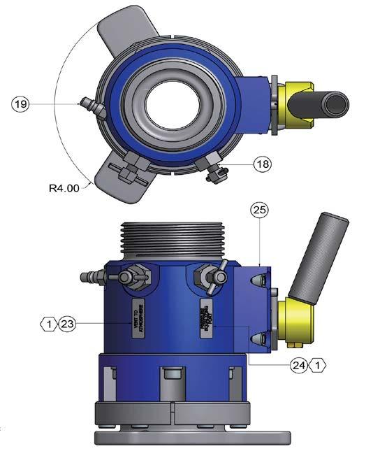
8 Page: 8 of 28 management and additional risk assessment requirements in the application of this procedure. The lead technician is responsible for the strict adherence to this work instruction. 5 SINGLE ISOLATION SERVICE VALVE MAINTENANCE The Service Valve contains line pressure while the plug is absent from the access fitting body during on-line service. The valve is rated to pressures up to 3600 psi, with a maximum operating temperature of +450 F (232 C)* and also meets NACE MR0175 and MR0103 standards. It incorporates one bypass valve allowing controlled pressure equalization of the retrieval tool during on-line retrievals and one bleed valve. The maintenance interval required for the service valve will be determined by the media acting upon the valve. Sand, grit, or metal chips may damage seats causing leaks which will require seat replacement. Occasional lubrication will be necessary to reduce opening torque. The use of a synthetic lubricant, such as Cosasco is recommended. *With high temperature seal options 5.1 Sour Gas Service The Single Bleed service valve applicable materials comply with the requirements of NACE standard MR0175, "Sulfide Stress Cracking Resistant Metallic Materials for Oil Field Equipment." As stated in this standard, Materials... are resistant to, but not necessarily immune to (sulfide stress cracking) under all service conditions." Thus, when the valve is used in sour environments, it must be thoroughly cleaned after use to help prevent corrosion and/or damage to internal materials. 5.2 Service Valve Disassembly

9 Page: 9 of 28
 and as a safe practice it is")
 at the hammer nut (4) end using a 5/16\" Allen")
(4) from the valve base(2) exposing the secondary set of")
10 Page: 10 of 28 Applicable to 3600 PSI service valve P/N ; service valve disassembles from the hammer nut end (access fitting body connection) and as a safe practice it is recommended to secure the valve in a vise to facilitate assembly/disassembly. 1. Remove the six 3/8 Allen head cap screws (15) at the hammer nut (4) end using a 5/16" Allen wrench. The cap screws(15) secure the hammer nut assembly(4) to the valve base(2). 2. Remove the hammer nut assembly(3)(4) from the valve base(2) exposing the secondary set of 3/8 Allen head cap screws.(15)
 to")

 and")

. 5.")
11 Page: 11 of Rotate ball(9) to closed position by turning the valve handle(8). 4. Remove handle(8) and handle stop(7) by removing the 5/16 bolt(17) from the valve handle(8). 5. Remove bonnet(25) by removing the 4 cap screws(27).

. 7.")

12 Page: 12 of Remove the secondary set of Allen head cap screws(15) from the valve body(1). 7. Remove the base(2) from the body(1). 8. Remove any seals as they become exposed from the removal of the ball valve(9).
 from body(1).")

 and/or stem seal(12) is")

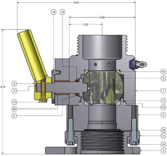
13 Page: 13 of Remove the valve ball(9) from body(1). Use of a small lab spatula can facilitate seal removal. 10. Remove the stem(5) from the valve body(1). (If, ball stem(5) and/or stem seal(12) is removed, a new stem seal(12) must be installed. 11. Remove the Vent to Atmosphere and Pressure Equalizing needle valves(18) from the main housing(1).


 and prepare the ball stem(5) for installation by greasing the ball stem seal(12), ball stem (5) and ball")
14 Page: 14 of Remove the quick connect coupling(19) from the main housing(1). 5.3 Service Valve Assembly 1. Clean all parts. Examine all seals and o-rings prior to assembly as they should be thoroughly inspected for nicks cuts or abrasions. It is highly recommended that seals and o-rings be replaced each time the service valve is disassembled. 2. Prepare a good work station with a vise to permit safe assembly of the valve. Clamp on the main housing with the vise and build up the service valve. 3. Grease the inner valve cavity, ball(9) and top seat(10). Install the top seat(10) and prepare the ball stem(5) for installation by greasing the ball stem seal(12), ball stem (5) and ball stem bushing(6). (If ball stem(5) and stem seal(12) were removed, a new stem seal(12) must be installed.)
 in the ball stem(5) then partially install")
 during installation. 5.")
 installed at this point.")
15 Page: 15 of Place the ball stem bushing(6) in the ball stem(5) then partially install the ball stem seal(12) with the spring side facing the ball stem bushing(6). Use caution not to pinch or bend the stem seal(12) during installation. 5. Install previous assembly into valve body(1) as straight as possible w/ out the bonnet(25) installed at this point. Careful use of channel locks may be used to seat ball stem(5) and seal(12). 6. Install ball valve(9).
 with bonnet bearing sleeve(26) onto the main housing(1).")


16 Page: 16 of Lube bonnet bearing sleeve(26) and place in bonnet(25). 8. Install bonnet(25) with bonnet bearing sleeve(26) onto the main housing(1). Apply antiseize to the socket head cap screws(27) for the bonnet before being tightened to 50 ftlb each in star pattern. 9. Grease the face seal(13) and carefully install into housing(1). Avoid bending or pinching the seal as it may get damaged and not provide an effective seal. The exposed spring portion should face toward the top seat(10), which is currently carrying the ball valve(9).
 walls of the inner and outer ball seat")
 and position the housing base(2) as if to")
 and apply anti-seize to the threads.")
 180 apart from each other in the housing base(2).")
17 Page: 17 of Grease the housing base(2) walls of the inner and outer ball seat cavity. 11. Install bottom seat(11) and position the housing base(2) as if to assemble. 12. Use two 1.5 socket head cap screws(15) and apply anti-seize to the threads. Position the two socket head cap screws(15) with split lock washers(16) 180 apart from each other in the housing base(2). Tighten the socket head cap screws(15) to the surface of the housing base(2) then tighten ¾ to 1 turn at a time to evenly close the service valve without damaging the face seal.
 is")
")

 and grease the bottom")
")
18 Page: 18 of Once the valve base(2) is closed install the remaining socket head cap screws(15) and tighten in a star pattern to 50 ft-lb each. 14. Install o-ring(20) on housing base(2) and grease the bottom surface. 15. Grease the hammer nut lock(3) where the hammer nut(4) is held in place.
 on the")
.")
 areas that make contact with")
19 Page: 19 of Install one half of the Hammer Nut lock(3) on the housing base(2) using 1.5 length socket head cap screws(15). Tighten head cap screws to 50 ft-lb each. 17. Grease the hammer nut(4) areas that make contact with the hammer nut lock(3) and housing base. 18. Place the hammer nut(4) into the hammer nut lock(3).
. 20.")

20 Page: 20 of Install the other half of the hammer nut lock(3). 20. Tighten the remaining head cap screws(15) to 50 ft-lb 21. Apply anti-seize to threads of the relief/bleed valve(18) assembly and grease the o- rings.
21 Page: 21 of Install relief/bleed valves(18) into the service valve housing(1). 23. Apply Teflon tape and anti-seize to the quick connect coupling(19). 24. Install quick connect coupling(19) into the main housing(1) of the service valve
 and")
 and handle(8) into the")
 to secure the handle in place. 27.")
, the handle should be in a")

22 Page: 22 of Apply red Loctite to the stop screw(14) and install stop screw in bonnet(25). 26. Insert handle stop(7) and handle(8) into the ball stem(5), once in place install the 5/16 bolt (17) to secure the handle in place. 27. Notice the orientation of the handle(8) and handle stop(7), the handle should be in a vertical position when ball valve is open and horizontal position when closed. Any other position can be attributed to the handle stop being installed incorrectly.

23 Page: 23 of Pressure test the service valve. Rated working pressure is 3600 psi (248 BAR) at temperatures to 450 F (232 C). Use of the extension handle will be necessary as initially the valve may be tight to operate with new seals. 6 SERVICING & PRESSURE TESTING OF RETRIEVAL EQUIPMENT IMPORTANT! Retriever and Service Valve must be pressure tested prior to use to ensure safe operation of tools! All Retrieval Tools and Service Valves must be pressure tested prior to use. The Field Technician using the equipment must possess current pressure test certificates for the retrieval equipment prior to commencing on-line retrievals operations. If the pipelines being worked on contain heavy debris, including, but not limited to; iron sulphide, sand, solids and iron oxide, the tool may become contaminated and difficult to use. The Field Technician will determine on a case by case basis if the tool needs to be stripped down or if it can be flushed out with either water or suitable cleaning agent without stripping the tools down. At the end of each major service visit, the tools will be stripped down, cleaned, seals replaced as necessary, re-assembled and pressure tested. See Section 6.2 for pressure testing procedure. 6.1 Pressure Testing Cosasco Pressure Test Rig
24 Page: 24 of 28 IMPORTANT! Retriever and Service Valve must be pressure tested prior to use to ensure safe operation of tools! All Retrieval Tools and Service Valves must be pressure tested prior to use. The Field Technician using the equipment must possess current pressure test certificates for the retrieval equipment prior to commencing on-line retrievals operations. NOTE: A pressure test can only be considered valid if the test meets the following minimum criteria: Prior to Mobilization: o o o On completion of a service campaign the Retrieval Tool and Service Valve must be disassembled, inspected, and fully serviced in accordance with the latest revision of the relevant Cosasco Maintenance. Upon servicing completion, providing a successful pressure test is completed the equipment may be mobilized for further service work within 7 days of the successful test. If the equipment is stored for a time period greater than 7 days from servicing, but no longer than 6 months it may be mobilized for further service work without being re-serviced, provided that a new successful pressure test has been completed within the 7 days prior to mobilization. If the equipment is to be stored for a period of greater than 6 months from being serviced then all equipment should be re-serviced and pressure tested every 6 months in accordance with the latest revision of the relevant Cosasco Maintenance. A successful pressure test will be required within the 7 days prior to mobilization for service work. Equipment mobilized for Field Service: o Once the retrieval equipment has been used in the field each online retrieval operation can be considered a successful pressure test for a further consecutive online retrieval operation with a validity of 12 hours. This duration between retrieval operations may be increased to 72 hours provided the tool is drained of any process fluids and the equipment internals have a suitable lubricant / protectant such as WD40 or Hydraulic Oil applied within the 12 hours following the last successful retrieval operation. o If it has been longer than 12 hours since the equipment was last used (or 72 hours if drained, flushed and lubricated) then the equipment must be disassembled, inspected, and fully serviced in accordance with the latest revision of the relevant Cosasco Maintenance. Upon servicing completion, providing a successful pressure test is completed the equipment may be used for further service work within 7 days of the successful test.
25 Page: 25 of 28 o If the retrieval equipment is used on any fitting containing debris/grit/sand which is deemed to affect the smooth operation of the equipment then the equipment at minimum must be drained, flushed and lubricated prior to further use. Special attention should be given to bleed valve and pressure gauge assemblies. A successful pressure test must then be carried out prior to the equipment being used for further retrieval operations. At the end of the shift, within a 12 hour period the equipment should then be disassembled, inspected, and fully serviced in accordance with the latest revision of the relevant Cosasco Maintenance. Upon servicing completion, providing a successful pressure test is completed the equipment may be used for further service work within 7 days of the successful test. IMPORTANT! If at any point either Retrieval Technician deems it necessary, for any reason, then the equipment must be stripped, cleaned, and serviced in accordance with the relevant Cosasco Maintenance. A successful pressure test will then be required prior to further use! 6.2 Pressure Testing Procedure 1. Fit the Service Valve to the access fitting on the pressure test rig by placing the hammer nut end of the valve onto the access fitting. 2. Turn the hammer nut clockwise down the external acme thread until the Service Valve is securely seated to the access fitting body. 3. Tighten the hammer nut using a brass or equivalent non sparking hammer. 4. Check that the bypass valve on the Service Valve is closed and the atmospheric bleed valve(s) is closed. Ball should be fully open. 5. The back pressure pump should be filled with hydraulic oil and a connecting hose (of a suitable pressure rating) used to connect the pump outlet to the quick coupler inlet fitted to the test rig. 6. With the pump on "Pressure Hold and at its low-pressure setting hand pump the oil into the pressure test rig. 7. Stop pumping once the oil level has passed the ball valve and close it. 8. Re-commence pumping and pressurize the assembly to the pressures stated in step 9. Leave pressurized for 15 minutes during each stage and observe that there is no pressure drop on the pressure test rig gauge. Note - There may be some drop in pressure during the 15 minute test period due to the compression of air still in the system and also due to oil being drawn back into the hand pump. If any pressure loss is due to leakage, this will be visible and immediately apparent.
26 Page: 26 of Pressure test the equipment to the following pressures: 5% of pressure rating of equipment. 10% of pressure rating of equipment. 20% of pressure rating of equipment. 50% of pressure rating of equipment. 100% of pressure rating of equipment. 150% of pressure rating of equipment. 10. After completing all six tests in step 9, release pressure in the hydraulic pump. 11. After completion of the pressure test, ensure the ball valve is opened and place the Retriever Tool onto the Service Valve. Turn the hammer nut union in a clockwise direction. 12. Tighten the hammer nut using a brass or equivalent non sparking hammer. 13. Ensure the bleed to atmosphere valve(s) on the Service Valve is closed and the Retriever bleed to atmosphere valve is opened. 14. With the hydraulic pump on "Pressure Hold and at its low-pressure setting hand pump the oil through the Service Valve and into the Retrieval Tool, ensuring the isolating valve is fully opened. 15. Continue pumping until all air is displaced from the Retriever atmospheric bleed valve. 16. Continue pumping and during a pump action, close the Retriever atmospheric bleed valve. 17. Continue pumping and pressurize the assembly to the pressures stated in step 9. Leave pressurized for 15 minutes during each stage and observe that there is no pressure drop on the pressure test rig gauge. Note: There may be some drop in pressure during the 15 minute test period due to the compression of air still in the system and also due to water being drawn back into the hand pump. If any pressure loss is due to leakage, this will be visible and immediately apparent. 18. During each stage the Retriever requires to be stroked to check the integrity of the seals over the full travel of the outer barrel After completing all six tests in step 9, release pressure in the hydraulic pump Check both the pressure gauges on the test rig and retrieval tool are at zero and drain off any residual fluid trapped in the retrieval tool and Service Valve. 20. Remove both the retrieval tool and Service Valve from the test rig. 21. Complete a pressure test certificate for both the Retriever and the Service Valve and file these in the dedicated maintenance folder for each tool. 22. A scanned copy of the original should also be filed accordingly. Note - There may be some drop in pressure during the 15 minute test period due to the compression of air still in the system and also due to water being drawn back into the hand pump. If any pressure loss is due to leakage, this will be visible and immediately apparent.
27 NOTES
28 Cosasco
COSASCO 6000 PSI SINGLE ISOLATION SERVICE VALVE (FR) MAINTENANCE
 MAINTENANCE") COSASCO 6000 PSI SINGLE ISOLATION SERVICE VALVE (FR) MAINTENANCE 11841 Smith Avenue Santa Fe Springs, CA 90670 Tel: (562) 949-0123 (800) 635-6898 Fax: (562) 949-3065 www.cosasco.com Page: 2 of 26 Revision
COSASCO 6000 PSI SINGLE ISOLATION SERVICE VALVE (FR) MAINTENANCE 11841 Smith Avenue Santa Fe Springs, CA 90670 Tel: (562) 949-0123 (800) 635-6898 Fax: (562) 949-3065 www.cosasco.com Page: 2 of 26 Revision
COSASCO 6000 PSI DOUBLE ISOLATION SERVICE VALVE MAINTENANCE
 COSASCO 6000 PSI DOUBLE ISOLATION SERVICE VALVE MAINTENANCE 11841 Smith Avenue Santa Fe Springs, CA 90670 Tel: (562) 949-0123 (800) 635-6898 Fax: (562) 949-3065 www.cosasco.com Page: 2 of 28 Revision History
COSASCO 3600 PSI SINGLE ISOLATION SERVICE VALVE (FR) MAINTENANCE
 MAINTENANCE") COSASCO 3600 PSI SINGLE ISOLATION SERVICE VALVE (FR) MAINTENANCE Rohrback Cosasco Systems, Inc. 11841 E. Smith Avenue Santa Fe Springs, CA 90670 Tel: (562) 949-0123 (800) 635-6898 Fax: (562) 949-3065 www.cosasco.com
COSASCO 3600 PSI SINGLE ISOLATION SERVICE VALVE (FR) MAINTENANCE Rohrback Cosasco Systems, Inc. 11841 E. Smith Avenue Santa Fe Springs, CA 90670 Tel: (562) 949-0123 (800) 635-6898 Fax: (562) 949-3065 www.cosasco.com
COSASCO RBS/RBSA RETRIEVER MAINTENANCE
 COSASCO RBS/RBSA RETRIEVER MAINTENANCE Work Instruction 11841 Smith Avenue Santa Fe Springs, CA 90670 Tel: (562) 949-0123 (800) 635-6898 Fax: (562) 949-3065 P/ N: 741031revH www.cosasco.com Page: 2 of
COSASCO MODEL 60 RETRACTABLE 1500 PSI SYSTEM RETRACTOR KIT Work Instruction
 COSASCO MODEL 60 RETRACTABLE 1500 PSI SYSTEM RETRACTOR KIT Work Rohrback Cosasco Systems, Inc. 11841 E. Smith Avenue Santa Fe Springs, CA 90670 Tel: (562) 949-0123 (800) 635-6898 Fax: (562) 949-3065 www.cosasco.com
COSASCO RSL RETRIEVER AND SINGLE ISOLATION SERVICE VALVE Work Instruction
 COSASCO RSL RETRIEVER AND SINGLE ISOLATION SERVICE VALVE 11841 Smith Avenue Santa Fe Springs, CA 90670 Tel: (562) 949-0123 (800) 635-6898 Fax: (562) 949-3065 www.cosasco.com Page: 2 of 42 Revision History
COSASCO RBS/RBSA RETRIEVER AND SINGLE ISOLATION SERVICE VALVE
 COSASCO RBS/RBSA RETRIEVER AND SINGLE ISOLATION SERVICE VALVE Rohrback Cosasco Systems, Inc. 11841 E. Smith Avenue Santa Fe Springs, CA 90670 Tel: (562) 949-0123 (800) 635-6898 Fax: (562) 949-3065 www.cosasco.com
COSASCO RSL RETRIEVER AND DOUBLE ISOLATION SERVICE VALVE Work Instruction
 COSASCO RSL RETRIEVER AND DOUBLE ISOLATION SERVICE VALVE 11841 Smith Avenue Santa Fe Springs, CA 90670 Tel: (562) 949-0123 (800) 635-6898 Fax: (562) 949-3065 www.cosasco.com Page: 2 of 45 Revision History
Work Instruction COSASCO TWO-INCH SYSTEM HOT TAP KIT
 COSASCO TWO-INCH SYSTEM HOT TAP KIT Work Instruction Rohrback Cosasco Systems, Inc. 11841 E. Smith Avenue Santa Fe Springs, CA 90670 Tel: (562) 949-0123 (800) 635-6898 Fax: (562) 949-3065 www.cosasco.com
WHEATLEY Series 822/820 Swing Check Valve
 Document Number: TC003001-12 Revision: 02 WHEATLEY Series 822/820 Swing Check Valve Installation, Operation, and Maintenance Manual TABLE OF CONTENTS BILL OF MATERIALS...3 SCOPE...4 INSTALLATION AND OPERATION
INDUSTRIAL VALVES MODELS: C62-A; C62-D. INSTRUCTION MANUAL Installation Operation Parts Service DIAPHRAGM BYPASS PRESSURE REGULATING VALVES
 INSTRUCTION MANUAL Installation Operation Parts Service IMPORTANT Record your Regulator model number and serial number here for easy reference: Model No. Serial No. Date of Purchase When ordering parts
INSTALLATION & MAINTENANCE INSTRUCTION
 ARCHON Industries, Inc Liquid Level Gauges Models: BT-LLG ND-LLG INSTALLATION & MAINTENANCE INSTRUCTION Instruction No.: 1014.2 Revision Issued: 3/01/03 Approved: Engineering Manager Warning ONLY QUALIFIED
WHEATLEY Series 500 Swing Check Valve
 Document Number: TC003001-13 Revision: 02 WHEATLEY Series 500 Swing Check Valve Installation, Operation, and Maintenance Manual TABLE OF CONTENTS BILL OF MATERIALS...3 SCOPE...5 INSTALLATION AND OPERATION
Needle valve. Contents. User s Manual. (1) Be sure to read the following warranty clauses of our product 1. (2) General operating instructions 2
 Be sure to read the following warranty clauses of our product 1. (2) General operating instructions 2") Serial No. H-V024-E-7 Needle valve User s Manual Contents (1) Be sure to read the following warranty clauses of our product 1 (2) General operating instructions 2 (3) General instructions for transportation,
Serial No. H-V024-E-7 Needle valve User s Manual Contents (1) Be sure to read the following warranty clauses of our product 1 (2) General operating instructions 2 (3) General instructions for transportation,
1 DRIVE INDUSTRIAL IMPACT WRENCH
 1 DRIVE INDUSTRIAL IMPACT WRENCH 92622 ASSEMBLY AND OPERATING INSTRUCTIONS 3491 Mission Oaks Blvd., Camarillo, CA 93011 Visit our Web site at http://www.harborfreight.com Copyright 2004 by Harbor Freight
VALVCHEQ BACKFLOW PREVENTERS FIGURE RP03
 Reduce pressure zone device suitable for high and medium hazard rated applications Flanged end connections FEATURES GENERAL APPLICATION The RP03 provides protection from both backsiphonage and backpressure
Installation Troubleshooting Maintenance Instructions Installation / Start-up
 Model ZW207 Installation Troubleshooting Maintenance Instructions Installation / Start-up NOTE: Flushing of all pipe lines is to be performed to remove all debris prior to installing valve. 1. For making
KENNEDY VALVE OPERATION & MAINTENANCE MANUAL
 2 54 ROTATING DISC GATE VALVE OPERATION & MAINTENANCE MANUAL Rel. 5/27/16 1 TABLE OF CONTENTS 3 General 3 Receipt & Inspection 4 Gate Valve Storage & Handling 5 6 Installation 7 Operation 8 Field Testing
INSTALLATION, OPERATION and MAINTENANCE MANUAL
 INSTALLATION, OPERATION and MAINTENANCE MANUAL TRUNNION MOUNTED BALL VALVE NEXTECH I ValvTechnologies, Inc. 5904 Bingle Road Houston, Texas 77092 U.S.A. Email: sales@valv.com www.valv.com 705_Nextech IOM
PRS(TC)4,8 USER MANUAL. Read the complete manual before installing and using the regulator.
4,8 USER MANUAL. Read the complete manual before installing and using the regulator.") PRS(TC)4,8 USER MANUAL Read the complete manual before installing and using the regulator. WARNING INCORRECT OR IMPROPER USE OF THIS PRODUCT CAN CAUSE SERIOUS PERSONAL INJURY AND PROPERTY DAMAGE. Due to
PRS(TC)4,8 USER MANUAL Read the complete manual before installing and using the regulator. WARNING INCORRECT OR IMPROPER USE OF THIS PRODUCT CAN CAUSE SERIOUS PERSONAL INJURY AND PROPERTY DAMAGE. Due to
Manual Actuated Boiler Blowdown Valves
 Manual Actuated Boiler Blowdown Valves Installation and Maintenance Instructions 1. Safety information 2. General product information 3. Installation 4. Operation 5. Maintenance 6. Spare parts p.1 1. Safety
FLANGED TWO-PIECE BALL VALVES
 INTRODUCTION This instruction manual includes installation, operation, and maintenance information for FNW flanged split-body ball valves. This manual addresses lever operated ball valves only. Please
Installation & Operation Manual Proven Quality since 1892
 Content 1. ERIKS operating companies 2. Product description 3. Requirements for maintenance staff 4. Transport and storage 5. Function 6. Application 7. Installation 8. Maintenance 9. Service and repair
Constant Pressure Crude Oil Container Model CPCCP
 Installation, Operations, and Maintenance Manual Constant Pressure Crude Oil Container Model CPCCP The information in this manual has been carefully checked for accuracy and is intended to be used as a
INSTALLATION, OPERATION & MAINTENANCE MANUAL
 INSTALLATION, OPERATION & MAINTENANCE MANUAL AWWA C500 SOLID WEDGE GATE VALVE 2 72 NRS and OS&Y Series 100 and Series 105 TABLE OF CONTENTS SECTION PAGE # Equipment List 2 General 3 Receipt and Inspection
Installation Instructions
 Installation Instructions BW Seals Uniseal Series Cartridge metal bellows single and dual seals Experience In Motion Description The Uniseal metal bellows seal series consists of: Uniseal I - Single seals
RS(H)10,15 USER MANUAL. Read the complete manual before installing and using the regulator.
10,15 USER MANUAL. Read the complete manual before installing and using the regulator.") RS(H)10,15 USER MANUAL Read the complete manual before installing and using the regulator. WARNING INCORRECT OR IMPROPER USE OF THIS PRODUCT CAN CAUSE SERIOUS PERSONAL INJURY AND PROPERTY DAMAGE. Due to
RS(H)10,15 USER MANUAL Read the complete manual before installing and using the regulator. WARNING INCORRECT OR IMPROPER USE OF THIS PRODUCT CAN CAUSE SERIOUS PERSONAL INJURY AND PROPERTY DAMAGE. Due to
LRS(H)4 USER MANUAL. Read the complete manual before installing and using the regulator.
4 USER MANUAL. Read the complete manual before installing and using the regulator.") LRS(H)4 USER MANUAL Read the complete manual before installing and using the regulator. WARNING INCORRECT OR IMPROPER USE OF THIS PRODUCT CAN CAUSE SERIOUS PERSONAL INJURY AND PROPERTY DAMAGE. Due to the
LRS(H)4 USER MANUAL Read the complete manual before installing and using the regulator. WARNING INCORRECT OR IMPROPER USE OF THIS PRODUCT CAN CAUSE SERIOUS PERSONAL INJURY AND PROPERTY DAMAGE. Due to the
LRS(H)4 Pressure-Reducing Regulator User Manual
4 Pressure-Reducing Regulator User Manual") LRS(H)4 Pressure-Reducing Regulator User Manual Read the complete manual before installing and using the regulator. 2 Safe Product Selection When selecting a product, the total system design must be considered
LRS(H)4 Pressure-Reducing Regulator User Manual Read the complete manual before installing and using the regulator. 2 Safe Product Selection When selecting a product, the total system design must be considered
SALCO PRODUCTS, INC. PRESSURE RELIEF VALVE STORAGE, INSTALLATION, OPERATING, MAINTENANCE/TESTING, AND INSPECTION INSTRUCTIONS
 STORAGE INSTRUCTIONS Until it is time to install a new or reconditioned valve on the car, the valve must be kept in its original packaging in order to protect it from dirt and damage. INSTALLATION INSTRUCTIONS
FLANGED TWO-PIECE BALL VALVES
 INTRODUCTION This instruction manual includes installation, operation, and maintenance information for FNW flanged split-body ball valves. This manual addresses lever operated ball valves only. Please
ACCUMULATOR OPERATING & MAINTENANCE INSTRUCTIONS
 ACCUMULATOR OPERATING & MAINTENANCE INSTRUCTIONS READ ALL INSTRUCTIONS PRIOR TO INSTALLATION AND OPERATION TO AVOID POSSIBLE INJURY Warning: Always consider any accumulator to contain pressure until proven
BSA6T and BSA64T Stainless Steel Bellows Sealed Stop Valves Installation and Maintenance Instructions
 1843950/3 IM-P184-03 ST Issue 3 BSA6T and BSA64T Stainless Steel Bellows Sealed Stop Valves Installation and Maintenance Instructions 1. General safety information 2. General product information 3. Installation
Pressure Regulators. Operating Instructions. Instrumentation
 Pressure Regulators Operating Instructions FAILURE OR IMPROPER SELECTION OR IMPROPER USE OF THIS PRODUCT CAN CAUSE DEATH, PERSONAL INJURY AND PROPERTY DAMAGE. This document and other information from the
PV4 and PV6 Piston Valves
 1181250/1 IM-P118-05 ST Issue 1 PV4 and PV6 Piston Valves Installation and Maintenance Instructions 1. Safety information 2. General product information 3. Installation 4. Commissioning 5. Operation 6.
THE HF-300 SERIES. Operating and Service Manual. Series includes all variants of HF-300/301
 THE HF-300 SERIES Operating and Service Manual Series includes all variants of HF-300/301 Issue A July 2015 1 TABLE OF CONTENTS 1. Description... 3 2. Installation... 3 3. Operation... 4 3.1. Spring Loaded...
Model 7989T Steel Pipe Squeezer Sch. 40 & Sch. 80. Operations Manual
 10-12 Steel Pipe Squeezer Sch. 40 & Sch. 80 Operations Manual 1.0 Introduction This manual is issued as a basic operation manual covering the Regent Model 7989T, Pipe Squeezer and Pump as manufactured
MMR Air Mask With. with Quick-Connect Hose
 MMR Air Mask With with Quick-Connect Hose Upgrade Kits P/N 10025120 Slide to Connect P/N 10050038 Slide to Connect w/ Solid Cover P/N 10038666 Push To Connect P/N 10050037 Push To Connect w/ Solid Cover
Hydraulic Piston Accumulators
 Ride Control Engineering Services PWCE Extendavator Paul Wever Construction Equipment Co., Inc. P.O. Box 85 401 Martin Drive Goodfield, IL 61742-0085 Phone (309) 965-2005 Fax (309) 965-2905 1-800-990-PWCE
DK ton, Double-acting, Die-type Crimping Tool
 INSTRUCTION MANUAL DK6040 60-ton, Double-acting, Die-type Crimping Tool Read and understand all of the instructions and safety information in this manual before operating or servicing this tool. Register
MSC-P and MSC-N Manifolds for Steam Distribution and Condensate Collection
 1170850/1 IM-P117-36 ST Issue 1 MSC-P and MSC-N Manifolds for Steam Distribution and Condensate Collection Installation and Maintenance Instructions 1. Safety information 2. General product information
INSTALLATION, MAINTENANCE & OPERATING INSTRUCTIONS 2-4 REDUCED PORT/ FULL PORT (5700/6700) ANSI CLASS 150/300/600/900/1500/2500 TRUNNION BALL VALVES
 ANSI CLASS 150/300/600/900/1500/2500 TRUNNION BALL VALVES") PBV-USA,Inc. 12735 Dairy Ashford. Stafford, Texas USA 77477 281-340-5400; 800-256-6193 FAX: 281-340-5499 INDUSTRIAL BALL VALVES IM0 69 April 2001 Rev 9 INSTALLATION, MAINTENANCE & OPERATING INSTRUCTIONS
PBV-USA,Inc. 12735 Dairy Ashford. Stafford, Texas USA 77477 281-340-5400; 800-256-6193 FAX: 281-340-5499 INDUSTRIAL BALL VALVES IM0 69 April 2001 Rev 9 INSTALLATION, MAINTENANCE & OPERATING INSTRUCTIONS
TriPod Safety Coupler Installation & Operating Instructions for Models TP4, TP5, TP6, and TP7
 TriPod Safety Coupler Installation & Operating Instructions for Models TP4, TP5, TP6, and TP7 March 2014 Form FVC097 - Rev03 IMPORTANT: KEEP THIS DOCUMENT WITH THE PRODUCT UNTIL IT REACHES THE END USER.
3M Liqui-Cel EXF-10x28 Series Membrane Contactor
 Membrane Contactors 3M Liqui-Cel EXF-10x28 Series Membrane Contactor Assembly and Disassembly Instructions 3M.com/Liqui-Cel TABLE OF CONTENTS I. Safety and Warning 3 II. Assembly Parts 4 III. Part Orientation
Un-Pressurized Orefice Fittings FIO EZ. Parts List and Operation Instructions TECHNICAL MANUAL. Dn 2-6 Class Lbs
 Un-Pressurized Orefice Fittings FIO EZ Parts List and Operation Instructions TECHNICAL MANUAL Dn 2-6 Class 150-600 Lbs US US 2 FIO EZ - MT 108-US - 05-2016 FIO EZ Important Instructions US Pietro Fiorentini
Hydraulic Punch Drivers
 SERVICE MANUAL 7804SB / 7806SB Quick Draw 7704SB / 7706SB Quick Draw Flex Quick Draw Hydraulic Punch Drivers Serial Codes AHJ and YZ Read and understand all of the instructions and safety information in
Wafer Check Valve. Contents. User s Manual. (1) Be sure to read the following description of our product warranty 1
 Be sure to read the following description of our product warranty 1") Serial No. H-V066-E-3 Wafer Check Valve User s Manual Contents (1) Be sure to read the following description of our product warranty 1 (2) General operating instructions 2 (3) General instructions for
Serial No. H-V066-E-3 Wafer Check Valve User s Manual Contents (1) Be sure to read the following description of our product warranty 1 (2) General operating instructions 2 (3) General instructions for
Models: C62/63/64-A/D
 Installation & Service C62-991-24A3 Models: C62/63/64-A/D Diaphragm Bypass Pressure Regulating Valves IMPORTANT Record your pump model number and serial number here for easy reference: Model No. Serial
Reduce pressure zone device suitable for high and medium hazard rated applications Flanged end connections
 VALVCHEQ Backflow Preventers Reduce pressure zone device suitable for high and medium hazard rated applications Flanged end connections Features General application The RP03 provides protection from both
Installation, Operation and Maintenance Manual for Back Pressure Regulator
 Installation, Operation and Maintenance Manual for Back Pressure Regulator Model 8860 2009 Groth Corporation IOM-8860 Rev. B 12541 Ref. ID: 95565 Page 2 of 13 Table of Contents I. INTRODUCTION 3 II. DESIGN
SCA Series Inverted Bucket Steam Traps
 0770050/5 IM-P077-06 ST Issue 5 SCA Series Inverted Bucket Steam Traps Installation and Maintenance Instructions 1. General safety information 2. General product information 3. Installation 4. Commissioning
RD(H)20/25 Pressure-Reducing Regulator User Manual
20/25 Pressure-Reducing Regulator User Manual") RD(H)20/25 Pressure-Reducing Regulator User Manual Read the complete manual before installing and using the regulator. 2 Safe Product Selection When selecting a product, the total system design must be
RD(H)20/25 Pressure-Reducing Regulator User Manual Read the complete manual before installing and using the regulator. 2 Safe Product Selection When selecting a product, the total system design must be
CB7 Bayonets Male & Female 1/4", 3/8, & 1/2 Size
 12501 Telecom Drive, Tampa, FL 33637 Ph: (813) 978-1000 Fax: (813) 977-3329 www.cpc-cryolab.com INSTALLATION, OPERATING, AND MAINTENANCE INSTRUCTIONS 17/3.5.6 Rev. 0 CB7 Bayonets Male & Female 1/4", 3/8,
310 SERIES TILT-TO-LOAD ROTATOR. The Specialist In Drum Handling Equipment
 OPERATOR S MANUAL FOR MORSE TILT-TO-LOAD DRUM ROTATOR SAFETY INFORMATION: While Morse Manufacturing Co. drum handling equipment is engineered for safety and efficiency, a high degree of responsibility
KBV21i and KBV40i Key Operated Boiler Blowdown Valves Installation and Maintenance Instructions
 4059051/3 IM-P405-48 EMM Issue 3 KBV21i and KBV40i Key Operated Boiler Blowdown Valves Installation and Maintenance Instructions 1. Safety information 2. General product information 3. Installation 4.
ROTATING DISK VALVES INSTALLATION AND MAINTENANCE 1. SCOPE 3 2. INFORMATION ON USAGE 3 3. VALVE TYPES 3 4. OPERATORS 5 5. VALVE CONSTRUCTION 6
 Sub Section INDEX Page Number 1. SCOPE 3 2. INFORMATION ON USAGE 3 3. VALVE TYPES 3 4. OPERATORS 5 5. VALVE CONSTRUCTION 6 6. INSTALLATION AND OPERATION 6 7. MAINTENANCE 8 8. REPAIR 9 9. ASSEMBLY 10 10.
A3S Bellows Sealed Stop Valve Installation and Maintenance Instructions
 1326050/3 IM-P132-11 ST Issue 3 A3S Bellows Sealed Stop Valve Installation and Maintenance Instructions 1 General safety information 2 General product information 3 Installation 4 Commissioning 5 Operation
Assembly Drawing: W-311B-A01, or as applicable Parts List: W-311B-A01-1, or as applicable Special Tools: , , &
 REDQ Regulators Model 411B Barstock Design Powreactor Dome Regulator OPERATION AND MAINTENANCE Contents Scope..............................1 Installation..........................1 General Description....................1
ANDERSON GREENWOOD SERIES 9000 POSRV INSTALLATION AND MAINTENANCE INSTRUCTIONS
 Procedure-assembly-functional test and performance requirements 1 SCOPE 1.1 This document establishes the general procedure for assembly, functional testing and normal performance requirements of low Series
MODEL 200 KNIFE GATE VALVES INSTALLATION & MAINTENANCE MANUAL
 MODEL 200 KNIFE GATE VALVES INSTALLATION & MAINTENANCE MANUAL Index 1. List of components / General arrangement 2. Description 3. Handling 4. Installation 5. Actuators / Operation 6. Maintenance a. Changing
INSTALLATION, OPERATION, AND MAINTENANCE MANUAL WELKER RELIEF VALVE
 INSTALLATION, OPERATION, AND MAINTENANCE MANUAL WELKER RELIEF VALVE MODELS RV-1 RV-2 RV-2CP RV-3 DRAWING NUMBERS AD017A[ ] AD018A[ ] AD020A[ ] AD282BO MANUAL NUMBER IOM-033 REVISION Rev. E, 3/28/2016 TABLE
3/8" Dr. Air Butterfly Impact Wrench
 8192106 3/8" Dr. Air Butterfly Impact Wrench Owner s Manual Read and understand all instructions before use. Retain this manual for future reference. Specifications Construction: Polished aluminum and
KBV21i and KBV40i Air Actuated Boiler Blowdown Valves
 4059051/1 IM-P405-48 AB Issue 1 KBV21i and KBV40i Air Actuated Boiler Blowdown Valves Installation and Maintenance Instructions 1. Safety information 2. General product information 3. Installation 4. Commissioning
Type BBS-03, BBS-05, BBS-06, BBS-25
 Type BBS-03, BBS-05, BBS-06, BBS-25 Sterile connection elements Sterile Verbindungselemente Raccords union stériles Operating Instructions Bedienungsanleitung Manuel d utilisation 1. THE OPERATING INSTRUCTIONS
Apollo Standard Port, Full Port & One Piece Flanged Ball Valves Installation, Operation, & Maintenance Manual
 I854000.D Apollo Standard Port, Full Port & One Piece Flanged Ball Valves Installation, Operation, & Maintenance Manual Introduction This manual presents guidelines for the Installation, Operation and
VALVCHEQ BACKFLOW PREVENTERS FIGURE RP03
 Reduce pressure zone device suitable for high and medium hazard rated applications BSP screwed connections FEATURES GENERAL APPLICATION The RP03 provides protection from both backsiphonage and backpressure
Operation and Maintenance Instructions
 Hydratight Limited Bentley Road South Darlaston West Midlands WS10 8LQ United Kingdom Tel: +44 121 50 50 600 Fax: +44 121 50 50 800 E-mail: enquiry@hydratight.com Website: www.hydratight.com TOP COLLAR
Copyright MAY, 2008 By Grizzly Industrial, Inc. Warning: No portion of this manual may be reproduced in any shape or form without the written
 MODEL G5789/G5790 13-PIECE 3 4" IMPACT WRENCH KIT INSTRUCTION MANUAL Copyright MAY, 2008 By Grizzly Industrial, Inc. Warning: No portion of this manual may be reproduced in any shape or form without the
Booster Pump PB4-60 Replacement Kits
 Booster Pump PB4-60 Replacement Kits FOR YOUR SAFETY - This product must be installed and serviced by a contractor who is licensed and qualified in pool equipment by the jurisdiction in which the product
M45 ISO Ball Valve DN25 to 150 Installation and Maintenance Instructions
 BAC 13310 IM-P133-42 ST Issue 2 M45 ISO Ball Valve DN25 to 150 Installation and Maintenance Instructions 1. General safety information 2. General product information 3. Installation 4. Commissioning 5.
750 Cable Cutter INSTRUCTION MANUAL
 INSTRUCTION MANUAL 750 Cable Cutter Read and understand all of the instructions and safety information in this manual before operating or servicing this tool. Register this product at www.greenlee.com
Type S301 & S302 Gas Regulators INTRODUCTION INSTALLATION. Scope of Manual. Description. Specifications. Type S301 and S302. Instruction Manual
 Fisher Controls Instruction Manual Type S301 & S302 Gas Regulators October 1981 Form 5180 WARNING Fisher regulators must be installed, operated, and maintained in accordance with federal, state, and local
INSTRUCTION MANUAL MST AFTERCOOLER SYSTEM MODEL
 INSTRUCTION MANUAL MST AFTERCOOLER SYSTEM MODEL 8059601 To be used with MST Model 8050501 Ambient Air Pump 7/12/05 2 TABLE OF CONTENTS GENERAL INFORMATION... 3 WARNING...4,5 UNPACKING AND AFTERCOOLER ASSEMBLY
WKM Model 320F Floating Ball Valve
 Date: 4 WKM Model 320F Floating Ball Valve Installation, Operation, and Maintenance Manual 1 Date: 4 All the information contained in this manual is the exclusive property of Cameron. Any reproduction
600 o F High Temperature Aging Cell Instruction Manual
 600 o F High Temperature Aging Cell Instruction Manual Manual No. D00654827, Revision E Instrument No. 102111608 600 o F High Temperature Aging Cell Instruction Manual 2013 Fann Instrument Company Houston,
In addition to this SOP, the policies and procedures of each operating company will be strictly observed by Rockwater personnel.
 SOP FB-009 (Revised MAR 2014) STANDARD OPERATING PROCEDURES-FLOWBACK Control of Trapped Pressure Section 1.0 Introduction and Background Rockwater Energy Solutions, Inc. (and all its affiliated and subsidiary
Copyright MAY, 2008 By Grizzly Industrial, Inc. Warning: No portion of this manual may be reproduced in any shape or form without the written
 MODEL G5791/G5792 17-PIECE 1 2" IMPACT WRENCH & RATCHET KIT INSTRUCTION MANUAL Copyright MAY, 2008 By Grizzly Industrial, Inc. Warning: No portion of this manual may be reproduced in any shape or form
Engineering Data Sheet
 Page 1 of 6 CE MARKING AND THE PRESSURE EQUIPMENT DIRECTIVE 97/23/EC Valves must be installed into a well designed system and it is recommended that the system be inspected in accordance with the appropriate
Bermad Pressure Reducing. Model: 42T
 Bermad Pressure Reducing Pilot Operated Pressure Control Valve Model: 42T Installation Operation Maintenance Manual (IOM) REV. 27.7.17 Page 1 of 12 Safety First BERMAD believes that the safety of personnel
Installation and Service Manual
 An Actuant Company Installation and Service Manual Heavy Duty Hydraulic Stabilization Legs CONTENTS Part # 3010003129 REV 0D Section Page 1.0 Receiving Instructions 2 2.0 Safety Issues 2 3.0 Hydraulic
KTM OM-2 SPLIT BODY FLOATING BALL VALVES INSTALLATION AND MAINTENANCE INSTRUCTIONS
 Before installation these instructions must be fully read and understood SECTION 1 - STORAGE 1.1 Preparation and preservation for storage All valves should be properly packed in order to protect the parts
Anti-flood device Model B-1
 December 4, 2009 Dry Systems 123a 1. DESCRIPTION The Anti-flood Device is required when Viking accelerators are installed on dry systems according to Viking Model E-1 Accelerator Trim Charts. In the SET
RHPS Series PRV 6 User Manual
 RHPS Series PRV 6 User Manual Read the complete manual before installing and using the valve. 1 WARNING Before removing a valve from the system for service, you must depressurize system purge the system
1700ESL Kamvalok Coupler
 PART #H32138PA November 2008 1700ESL Kamvalok Coupler OPW Transport Series Dry Disconnect Couplings are considered the standard of the industry. For use on multi-compartment petroleum, solvent and chemical
APCO ARV CLEAN WATER AIR RELEASE VALVES. Model 50A
 APCO ARV CLEAN WATER AIR RELEASE VALVES Model 50A Instruction D12013 February 2017 Instructions These instructions provide installation, operation and maintenance information for APCO ARV Clean Water Air
Wilo Triple Duty Valve / Triple Service Valve Installation and operating instructions
 Wilo Triple Duty Valve / Triple Service Valve Installation and operating instructions WIL-IO-SD-001-10 1 Description The Triple Duty Valve (TDV) / Triple Service Valve (TSV) is a quiet operating heavy-duty
REL-510H WARNING NOTICE 12 TON SINGLE ACTING REMOTE HYDRAULIC CRIMPING HEAD
 OPERATORS ORS GUIDE REL-510H 12 TON SINGLE ACTING REMOTE HYDRAULIC CRIMPING HEAD Compatible with U style and RELIABLE R12 shell type 12 ton compression dies. RELIABLE EQUIPMENT & SERVICE CO., INC. 92 Steamwhistle
Product Information News
 Product Information News MMR SECOND STAGE REGULATOR VALVE CORE MSA has changed its recommended rebuilding of the MMR Second Stage Regulator s bypass sleeve assembly during the annual inspection. Based
Types 749B and R130 Changeover Manifolds
 Instruction Manual MCK-1179 Types 749B and R130 June 2012 Types 749B and R130 Changeover Manifolds TYPE HSRL-749B TYPE 64SR/122 TYPE R130/21 TYPE 749B/21 Figure 1. Changeover Manifolds and Regulator Assemblies
Operating and maintenance manual Filter and reducing station Series / 1.0
 Operating and maintenance manual Filter and reducing station Series 961 04.2017 / 1.0 Original instructions ARCA Regler GmbH. All rights reserved. Cover picture background: Freepik.com ARCA Regler GmbH
DC5A. Cyclone Separator Trap for Air. Copyright 2015 by TLV Co., Ltd. All rights reserved ISO 9001/ ISO MA-03 (DC5A) 19 June 2015
 19 June 2015") 172-65205MA-03 (DC5A) 19 June 2015 ISO 9001/ ISO 14001 Manufacturer Kakogawa, Japan is approved by LRQA LTD. to ISO 9001/14001 Cyclone Separator Trap for Air DC5A Copyright 2015 by TLV Co., Ltd. All rights
172-65205MA-03 (DC5A) 19 June 2015 ISO 9001/ ISO 14001 Manufacturer Kakogawa, Japan is approved by LRQA LTD. to ISO 9001/14001 Cyclone Separator Trap for Air DC5A Copyright 2015 by TLV Co., Ltd. All rights
Welker Sampler. Model GSS-1. Installation, Operation, and Maintenance Manual
 Installation, Operation, and Maintenance Manual Welker Sampler Model GSS-1 The information in this manual has been carefully checked for accuracy and is intended to be used as a guide to operations. Correct
UIB30 and UIB30H Sealed Inverted Bucket Steam Traps for use with Pipeline Connectors
 1130050/4 IM-P113-02 ST Issue 4 UIB30 and UIB30H Sealed Inverted Bucket Steam Traps for use with Pipeline Connectors Installation and Maintenance Instructions 1. Safety information 2. General product information
20 Ton SD Shop Press Operating Instructions
 20 Ton SD Shop Press Operating Instructions MODEL NO. 850SD Hazard Symbols Used in the Manuals This manual includes the hazard symbols defined below when the operations or maintenance job involves a potential
INSTALLATION INSTRUCTIONS. CVS 67CFR Pressure Reducing Instrument Supply Regulator INTRODUCTION
 INSTALLATION INSTRUCTIONS CVS 67CFR Pressure Reducing Instrument Supply Regulator INTRODUCTION The CVS Controls 67CFR Filter regulator is a pressure reducing supply regulator typically used for pneumatic
TITAN FLOW CONTROL, INC.
 PREFACE: This manual contains information concerning the installation, operation, and maintenance of Titan Flow Control (Titan FCI) Simplex Basket Strainers. To ensure efficient and safe operation of Titan
APCO ASU-SCAV & ASU-CAV SINGLE BODY COMBINATION AIR VALVES
 APCO ASU-SCAV & ASU-CAV SINGLE BODY COMBINATION AIR VALVES Instruction D12039 December 2015 Instructions These instructions provide installation, operation and maintenance information for the. They are
PDY TON HYDRAULIC CRIMPING TOOL WARNING
 OPERATORS ORS GUIDE PDY-1220 12 TON HYDRAULIC CRIMPING TOOL All information found in this guide must be read and understood before use or testing of this tool. Failure to read and understand these warnings
HAYWARD FLOW CONTROL Series PBV Back Pressure Valve and Series RPV Pressure Relief Valve INSTALLATION, OPERATION, AND MAINTENANCE INSTRUCTIONS
 HAYWARD FLOW CONTROL Series PBV Back Pressure Valve and Series RPV Pressure Relief Valve INSTALLATION, OPERATION, AND MAINTENANCE INSTRUCTIONS Page 1 of 20 Page 2 of 20 TABLE OF CONTENTS Safety Warnings
299H Series. Introduction. P.E.D. Categories. Specifications. Installation. Warning. Installation Guide English September 2012
 Installation Guide English September 2012 299H Series Introduction This Installation Guide provides instructions for installation, startup, and adjustment of 299H Series regulators. To receive a copy of