AIR-OPERATED BELLOWS PUMP MANUAL
|
|
|
- Wesley Marshall
- 6 years ago
- Views:
Transcription
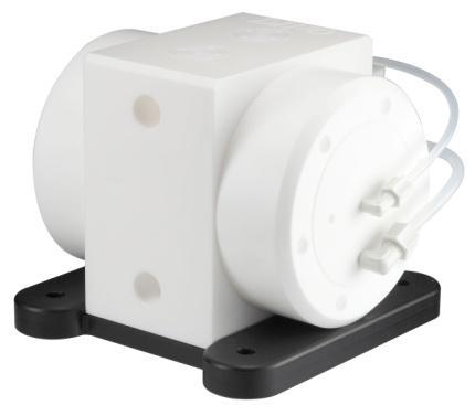

1 AIR-OPERATED BELLOWS PUMP MANUAL V.E2
2 CONTENTS Ⅰ GENERAL... 3 Ⅱ UPON RECEIVED... 3 Ⅲ CAUTION BEFORE OPERATION 3-4 Ⅳ MODLE INDICATION... 4 Ⅴ TECHNICAL DATA... 5 Ⅵ OPERATION TEMPERATURE 5 Ⅶ INSTALLATION.. 6 Ⅷ PEROFRMANCE CURVE /8 HE40/HT40/HT40-F.. 7 1/2 HE50/ HT50/ HT50-F /4 HE80/ HT80/ HT80-F 8 1 HE100/ HT100/ HT100-F. 8 Ⅸ EXPLODED DRAWING 9 Ⅹ SPARE PARTS LIST ⅩⅠ DIMENSION ⅩⅡ SECTION DRAWING ⅩⅢ OPTIONAL ACCESSORY. 13 ⅩⅣ TROUBLESHOOTING. 14 ⅩV WARRANTY / SERVICE
3 Ⅰ GENERAL Thank you for purchasing DINO AIR-OPERATED BELLOWS PUMP. Each pump follows standard test procedure and is conducted testing in CLASS 100 cleanroom. Caution: Before installation, please read through this manual carefully and follow the installation instructions. Ⅱ UPON RECEIVED 1. Please check if the mark outside box is same as what you ordered. 2. Please open the box to check if the mufflers or air pipes are loosened, must to re-install and make sure they are tightened up to the pump. 3. Please check if the pump or accessories are damaged during shipping. Caution: Do not lift pump by muffler to prevent damage. Ⅲ CAUTION BEFORE OPERATION 1. Before pumping, please follow local Industrial Safety and Health Association rule and wear appropriate goggles, gloves, protective clothing and safety shoes according to the pumping liquid. 2. Professional person should observe during pump operation. 3. Pump must be operated within its performance. Failure due to misuse is not under warranty. 4. DINO shall not be liable for any damage arising from inadequately modify or replace non-dino s spare parts by yourself. 5. Please release liquid inside the pump and flush with suitable liquid if the pump will not be used for a long time and storage in dry and well-ventilated place. 6. If the pumping liquid contains poisonous or might emit odors, please keep workspace well-ventilated and wear the regulation protective equipment. 7. Before returning the pump to DINO, should be drained the remaining liquid in the pump as empty as possible and flushed with suitable liquid to avoid any accidents during shipping. 8. During operation, please ensure the pipe have been full of liquid and open the valve on the inlet and outlet ports. 3
4 9. Before shutting off the pump, please closed inlet valve and ensure liquid have been released. Then shut off the air supply. 10. Do not transfer the liquid that is easily crystalize, rough petroleum solvents or the liquid containing slurries, thereby shortening the pump life. 11. Before using slurry or stripper, please contact us or designated distributor. 12. Please contact us or designated distributor if the liquid temp. is below 5 degree C. 13. The Maximum viscosity is 100 cps. Ⅳ MODEL AND MATERIAL INDICATION HT 50 F TE TE TE ** Pump material: HE:PE HT:PTFE Temperature: F:High temp. Spring valve: TE:PTFE-TFM Other spec./accessories X1: stroke counter Inlet/ Outlet: 40:3/8 NPT 50:1/2 NPT 80:3/4 NPT 100:1 NPT Valve seat: PE:PE TE:PTFE-TFM Bellows: TE:PTFE-TFM 4
5 Ⅴ TECHNICAL DATA *high-temperature resistance PTFE material Model HE40/ HE50 HE80/HE100 HT40/ HT50 HT80/HT100 HT40F/ HT50F HT80F/HT100F Weight 6kg 8.4kg 8.6kg 12.5kg 10.8kg 15.4kg Material PE PE PTFE PTFE *PTFE *PTFE Air pressure operating 1~7kg 1~7kg 1~7kg 1~7kg 1~7kg 1~7kg range Capacity 42 / 56 (L/min) 78 / 94 (L/min) 42 / 56 (L/min) 78 /94 (L/min) 42 / 56 (L/min) 78 / 94 (L/min) Liquid 3/8 / ½ ¾ / 1 3/8 / ½ ¾ / 1 3/8 / ½ ¾ / 1 outlet/inlet Air connection ¼ ¼ ¼ ¼ ¼ ¼ Max. operating temp. Suction lift, dry 2mwc 2mwc 2mwc 2mwc 2mwc 2mwc Suction lift, wet 5mwc 5mwc 5mwc 5mwc 5mwc 5mwc Max. particle 0.5mm 0.5mm 0.5mm 0.5mm 0.5mm 0.5mm Per cycle 0.075L/0.094L 0.22L/0.26L 0.075L/0.094L 0.22L/0.26L 0.075L/0.094L 0.22L/0.26L Max. pump speed 532cpm 367cpm 532cpm 367cpm 532cpm 367cpm (Test condition:room temperature pure water, fully open inlet and outlet valve) Ⅵ OPERATION TEMPERATURE Model HE40/50/80/100 HT40/50/80/100 HT40F/50F/80F/100F Operating pressure 1 bar bar bar bar bar bar bar *Temperature varies with pressure. 5
6 Ⅶ INSTALLATION 1. Before installation, make sure to keep enough space for pipe connection and maintain. 2. DINO air-operated bellows pump requires supply CDA (Clean Dry Air) or nitrogen and use the proper sized air piping. 3. Before installation, please clean the scraps from pipework left inside suction and discharge pipe to avoid the scraps flow into pump and stabbing the bellows. 4. Make sure all the connectors are installed properly and tighten. 5. When installing the piping connection, please consider and add the gross value of pipe loss into capacity demand. (Horizontal and vertical distance at outlet and inlet, gravity and viscosity) Air driven pump discharge pressure has to large than gross value of pipe loss when air supply pressure has to under maximum operating pressure. For instance, if the gross value of pipe loss is 2 kg/ cm2, the air supply pressure has to be higher than the gross pipe lose pressure under normal operation. 6. Please install the pump as close tank as possible to the tank. 7. Pump can normally operate if install on not 100% completely horizontal position. DINO Bellows pump equips with check spring valve instead of check valve balls, so pump no horizontal installation doubt. 8. To avoid particle into bellows, please install low flow-resistance filter in the inlet line. 9. Operating temperature Please refer to the temperature and pressure operating condition list (page 6). If temperature or pressure over limited and cause pump damage, DINO does not warrant such damage. 10. Particle size in Liquid should be under 0.5mm. If size over 0.5mm, it will cause clogged and bellows deformation. DINO does not warrant such damage. 11. Liquid Boiling points: In the event of pumping liquid at or near boiling point, it must be remembered that the boiling temperature of any liquid reduces under vacuum conditions. Depending on the liquid and temperature of outlet/inlet lines, the situation might be different. Boiling liquid in the inlet line causes a pump running erratically thereby shortening its life. 12. Selecting a pump which its performance exceed the operating conditions. This can prolong its life expectancy. 13. FLAMMABLE SOLVENTS High purity pumps are frequently used to pump flammable solvents. High purity pumps should be constructed by insulating materials (PTFE and PFA) and properly grounded to avoid ignition caused by static charge. Caution: The operators who operate flammable solvents should be having proper vocational training and understand the liquid characteristic. 6
7 Ⅷ PERFORMANCE CURVE 3/8 HE40/ HT40/ HT40-F 1/2 HE50/ HT50/ HT50-F *Test condition: room temperature pure water; fully open inlet and outlet valve. *Performance curve might vary ±10% based on applications. 7

8 3/4 HE80/ HT80/ HT80-F 1 HE100/ HT100/HT100-F *Test condition:room temperature pure water; fully open inlet and outlet valve. *Performance curve might vary ±10% based on applications. 8

9 Ⅸ EXPLODED DRAWING * * * * * * * * 9
10 Ⅹ SPARE PARTS LIST DINO Bellows Pump Model HT40F-TETETE HT40- TETETE HE40- PETETE HT50F-TETETE HT50- TETETE HE50- PETETE HT80F-TETETE HT80- TETETE HE80- PETETE Item Description Q ty Material Part No. Part No. 1. Pump Body 1 PE PTFE H H1-T H H1-T H H1-T Shaft sleeve 2 PTFE-TFM H1-T H1-T Shaft 1 PTFE-TFM H1-T H1-T Bellows 2 PTFE-TFM H1-T H1-T Valve rod, bellows 6. O-ring set, Side cap 7. Side housing 2 PP 2 PEEK H H PTFE H H PTFE 8. Side cap 2 UPE 9. O-ring, side cap 10. O-ring, side cap PTFE H H1-T H H1-T H H1-T H H1-T VT H H VT H H Spring valve 4 PTFE-TFM H1-T H1-T Valve seat 4 PE PTFE-TFM H H1-T H H1-T Base Plate 1 UPE H H O-ring, Base Plate 15. Screw, *16. *17. Base Plate Air valve casing O-ring (big), side plate, air valve 5 VT H H UPE H H UPE H H VT H H *18. Air valve 1 PETP H H *19. * O-ring set, air valve O-ring, air valve 6 PTFE H H VT H H HT100F-TETETE HT100- TETETE HE100- PETETE H H1-T
11 *21. *22. *23. Shuttle shaft, air valve Side cap, air valve O-ring (small), air valve, side cap 24. Air Inlet Elbow 25. Air Inlet Elbow Repair Kit * Air valve assembly kit number is HS-1. Air valve casing kit number is HS-2. Air valve kit number is HS-3. 1 CERAMIC H H PETP H H VT H H PP PVDF 2 PP PVDF 26. Air joint 2 PP 27. Air supply pipe 28. Air supply pipe 29. Screw, air valve PVDF 2 PE PFA 2 PE PFA H H1-T H H1-T H H1-T H H1-T H H1-T H H1-T H H1-T H H1-T H H1-T H H1-T PEEK H H Muffler 2 PP H H


 12")
12 ⅩⅠ OUTLINE DIMENSION Model:HE40, HE50, HT40, HT50, HT40F, HT50F ( The dimensions are not included air inlet joint, liquid outlet/inlet joint.) Model:HE80, HT80, HT100, HT80F, HT100F ( The dimensions are not included air inlet joint, liquid outlet/inlet joint.) 12
 Pump Model HT100H-T1 *PTFE/PTFE HT80-F,HT100-F HT100H-T2 *PTFE/PTFE 1 NPT Piping type HT50H-T1")
 Stroke counter: H2-58-80001 (e.g. HE50-PETETE-X1 for equipped stroke counter model) 13")
13 ⅩⅡ SECTION DRAWING Bellows Spring Valve ⅩIII OPTIONAL ACCESSORY 1) Pulsation dampener *high-temperature resistance PTFE. Dampener Model Material (Wetted/ Non-wetted) Pump Model HT100H-T1 *PTFE/PTFE HT80-F,HT100-F HT100H-T2 *PTFE/PTFE 1 NPT Piping type HT50H-T1 *PTFE/PTFE HT40-F, HT50-F HT50H-T2 *PTFE/PTFE 1/2 NPT Piping type HT100-T1 PTFE/NPP HE80, HT80, HE100, HT100 HT100-T2 PTFE/NPP 1 NPT Piping type HT50-T1 PTFE/NPP HE40, HT40, HE50, HT50 HT50-T2 PTFE/NPP 1/2 NPT Piping type 2) Stroke counter: H (e.g. HE50-PETETE-X1 for equipped stroke counter model) 13
14 ⅩIV TROUBLESHOOTING 1. When pumps cannot run normally in first operation please check if pumps are damaged during shipping. Make sure the air pipe and all connectors have been tightening, and then following the manual to regulate air pressure. If the problem still remains after above inspections, please contact us or designated distributor. 2. In normal operation, when pumps cannot transfer liquid, please check if the inlet and outlet valves are opened and clogged. If the problem still remains after conducting above requested inspection, please contact us or designated distributor. Please contact the designated distributor or mail to if any problems occur. Do not disassemble or replace the pumps and parts without our authorization. ⅩV WARRANTY/ SERVICE DINO TEHCNOLOGY CO., LTD. warrants the end user one year after purchase date. During this period, consumable, failures due to negligence, natural disasters or any unauthorized disassembly are not under warranty. When you are going to order spare parts, please offer information as following items: 1. Model/Serial Number 2. Material 3. Bore size 4. Part Number (please refer to the page11.12 in this manual) Please contact the designated distributor or to 14
15

16 DINO TECHNOLOGY CO., LTD. No , Ln. 458, Sec. 1, Wunhua N. Rd., Linkou Dist., New Taipei City 244, Taiwan Tel: Fax: Webpage: Mail: info@dino.com.tw
2 I All-Flo Pump Co.
 2 I All-Flo Pump Co. 3I All-Flo Pump Co. Model Designation Matrix Pump Dimensions A B C D F H I J K L P300 18.90" 22.83" 31.50" 3.94" 15.28" 27.17" 1.57" 2.95" 15.55" 19.49" (480 mm) (580 mm) (800 mm)
2 I All-Flo Pump Co.
 2 I All-Flo Pump Co. 3I All-Flo Pump Co. Model Designation Matrix PRODUCT SERIES PUMP SIZE FLUID CONNECTI INTERM INNER CHAM ON TYPE FLUID C HAMBER MANIFOLDS EDI A TE/ BER O-RINGS VAL VE SEAT VALVE/BAL
Needle valve. Contents. User s Manual. (1) Be sure to read the following warranty clauses of our product 1. (2) General operating instructions 2
 Be sure to read the following warranty clauses of our product 1. (2) General operating instructions 2") Serial No. H-V024-E-7 Needle valve User s Manual Contents (1) Be sure to read the following warranty clauses of our product 1 (2) General operating instructions 2 (3) General instructions for transportation,
Serial No. H-V024-E-7 Needle valve User s Manual Contents (1) Be sure to read the following warranty clauses of our product 1 (2) General operating instructions 2 (3) General instructions for transportation,
HAYWARD FLOW CONTROL Series PBV Back Pressure Valve and Series RPV Pressure Relief Valve INSTALLATION, OPERATION, AND MAINTENANCE INSTRUCTIONS
 HAYWARD FLOW CONTROL Series PBV Back Pressure Valve and Series RPV Pressure Relief Valve INSTALLATION, OPERATION, AND MAINTENANCE INSTRUCTIONS Page 1 of 20 Page 2 of 20 TABLE OF CONTENTS Safety Warnings
accidents which arise due to non-observance of these instructions and the safety information herein. SPECIFICATIONS
 18 GAUGE 2 INCH BRAD NAILER Model: 7555 CALIFORNIA PROPOSITION 65 WARNING: You can create dust when you cut, sand, drill or grind materials such as wood, paint, metal, concrete, cement, or other masonry.
accidents which arise due to non-observance of these instructions and the safety information herein. SPECIFICATIONS
 18 GAUGE 1-1/4 INCH BRAD NAILER Model: 7611 CALIFORNIA PROPOSITION 65 WARNING: You can create dust when you cut, sand, drill or grind materials such as wood, paint, metal, concrete, cement, or other masonry.
80 Litre Suction Oil Drainer
 80 Litre Suction Oil Drainer Please dispose of packaging for the product in a responsible manner. It is suitable for recycling. Help to protect the environment, take the packaging to the local amenity
AIR-OPERATED DOUBLE DIAPHRAGM PUMP USER S MANUAL
 00, 0, 000 00, 000, 00 A. TECHNICAL INFORMATION Model 00 Inlet/Outlet " Air Inlet /" 0 / 000 /" /" 00 /" /" 000 /" /" 00 /" /" Flow Rate GPM/ 0LPM GPM/ 0LPM GPM/ LPM GPM/ LPM GPM/ 0LPM GPM/ 0LPM Maximum
OWNER S TECHNICAL MANUAL
 EL SERIES OWNER S TECHNICAL MANUAL DP7002 1 Air Operated Diaphragm Pump Description The DP7002 1 air operated diaphragm pump is the ideal device for the pumping, transfer and dispensing of chemical liquids,
97C COMPRESSOR KIT 12V PART NO C COMPRESSOR KIT 24V PART NO C COMPRESSOR KIT PART NO
 97C COMPRESSOR KIT 12V PART NO. 00097 97C COMPRESSOR KIT 24V PART NO. 02497 98C COMPRESSOR KIT PART NO. 00098 97C 98C IMPORTANT: It is essential that you and any other operator of this product read and
42045 Heavy Duty ADA Base Model Kit: 85/105 PSI (ADA Compressor Only) Heavy Duty ADA Base Model Kit: 110/145 PSI (ADA Compressor Only)
 Heavy Duty ADA Base Model Kit: 110/145 PSI (ADA Compressor Only)") 42045 Heavy Duty ADA Base Model Kit: 85/105 PSI (ADA Compressor Only) 42047 Heavy Duty ADA Base Model Kit: 110/145 PSI (ADA Compressor Only) 45052 Constant Duty ADA Base Model Kit: 85/105 PSI (ADA Compressor
42045 Heavy Duty ADA Base Model Kit: 85/105 PSI (ADA Compressor Only) 42047 Heavy Duty ADA Base Model Kit: 110/145 PSI (ADA Compressor Only) 45052 Constant Duty ADA Base Model Kit: 85/105 PSI (ADA Compressor
TOP VALVE. Pat. #5,857,486 & 5,944,050. Mid-Range Pressure PSIG Back Pressure and Pressure Relief Valves. Instruction Manual
 TOP VALVE Pat. #5,857,486 & 5,944,050 Mid-Range Pressure 50 232 PSIG Back Pressure and Pressure Relief Valves Instruction Manual Please Note: This instruction manual provides detailed information and instructions
TOP VALVE. Pat. #5,857,486 & 5,944,050. High Temperature: max. 300 F (149 C) Back Pressure And Pressure Relief Valves. Instruction Manual
 Back Pressure And Pressure Relief Valves. Instruction Manual") TOP VALVE Pat. #5,857,486 & 5,944,050 High Temperature: max. 300 F (149 C) Back Pressure And Pressure Relief Valves Instruction Manual PLEASE NOTE: This instruction manual provides information and instructions
TOP VALVE Pat. #5,857,486 & 5,944,050 High Temperature: max. 300 F (149 C) Back Pressure And Pressure Relief Valves Instruction Manual PLEASE NOTE: This instruction manual provides information and instructions
SAFETY MANUAL FOR FLAMMABLE PRODUCT TRANSFER
 SAFETY MANUAL FOR FLAMMABLE PRODUCT TRANSFER SUPPLIMENT TO eom IMPORTANT READ THIS MANUAL BEFORE PRODUCT INSTALLATION, OPERATION, INSPECTION & MAINTENANCE Tougher and more rigid guidelines are being established
ACCU-PULSE Installation and Operation Instructions
 ACCU-PULSE Installation and Operation Instructions Pump Discharge Installation: Chargeable Models Step 1: Mounting Position Mount ACCU-PULSE as close to the pump discharge as possible to absorb the pulse
Operation and Maintenance Manual for GENTEC Model 881VR Continuous/Intermittent Digital Suction Regulators
 Operation and Maintenance Manual for GENTEC Model 881VR Continuous/Intermittent Digital Suction Regulators Genstar Technologies Co., Inc. 4525 Edison Avenue Chino, CA 91710 USA TEL 909-0-272 FAX 909-0-485
OPERATING INSTRUCTIONS MANUAL FOR QACV PNEUMATIC DOSING PUMP
 This operating instructions contains safety information that if ignored can endanger life or result in serious injury. They are indicated by this icon. Use of this pump with radioactive chemicals is forbidden!
SPQ-1A Beach Volleyball System. Instruction
 SPQ-1A Beach Volleyball System Instruction Content Ⅰ Product Components Brief Ⅱ Embedding of Ground Sockets Ⅲ Installation of Beach Volleyball Net Ⅳ Installation of Antennas Ⅴ Operation of Wire Tension
SSFU SUPER SPRAYFAST UNIVERSAL ADHESIVE APPLICATOR
 S S F U SSFU SUPER SPRAYFAST UNIVERSAL ADHESIVE APPLICATOR MACHINERY DIVISION OWNER S MANUAL UNIT INSTRUCTIONS Please follow all SSFU Safety Instructions. Contact your Duro Dyne Tech Service if you have
RS(H)10,15 USER MANUAL. Read the complete manual before installing and using the regulator.
10,15 USER MANUAL. Read the complete manual before installing and using the regulator.") RS(H)10,15 USER MANUAL Read the complete manual before installing and using the regulator. WARNING INCORRECT OR IMPROPER USE OF THIS PRODUCT CAN CAUSE SERIOUS PERSONAL INJURY AND PROPERTY DAMAGE. Due to
RS(H)10,15 USER MANUAL Read the complete manual before installing and using the regulator. WARNING INCORRECT OR IMPROPER USE OF THIS PRODUCT CAN CAUSE SERIOUS PERSONAL INJURY AND PROPERTY DAMAGE. Due to
Wafer Check Valve. Contents. User s Manual. (1) Be sure to read the following description of our product warranty 1
 Be sure to read the following description of our product warranty 1") Serial No. H-V066-E-3 Wafer Check Valve User s Manual Contents (1) Be sure to read the following description of our product warranty 1 (2) General operating instructions 2 (3) General instructions for
Serial No. H-V066-E-3 Wafer Check Valve User s Manual Contents (1) Be sure to read the following description of our product warranty 1 (2) General operating instructions 2 (3) General instructions for
PRS(TC)4,8 USER MANUAL. Read the complete manual before installing and using the regulator.
4,8 USER MANUAL. Read the complete manual before installing and using the regulator.") PRS(TC)4,8 USER MANUAL Read the complete manual before installing and using the regulator. WARNING INCORRECT OR IMPROPER USE OF THIS PRODUCT CAN CAUSE SERIOUS PERSONAL INJURY AND PROPERTY DAMAGE. Due to
PRS(TC)4,8 USER MANUAL Read the complete manual before installing and using the regulator. WARNING INCORRECT OR IMPROPER USE OF THIS PRODUCT CAN CAUSE SERIOUS PERSONAL INJURY AND PROPERTY DAMAGE. Due to
200 PSI COMPRESSORS - MODEL NUMBERS
 200 PSI COMPRESSORS - MODEL NUMBERS 380C AIR COMPRESSOR KIT PART NO. 38033 480C AIR COMPRESSOR KIT PART NO. 48043 380C 480C IMPORTANT: It is essential that you and any other operator of this product read
Geotech 1.66 Auto-Reclaimer Installation and Operation
 Geotech 1.66 Auto-Reclaimer Installation and Operation Rev 10/19/12 Part # 16600165 TABLE OF CONTENTS CHAPTER 1: SYSTEM DESCRIPTION... 3 FUNCTION AND THEORY... 3 SYSTEM COMPONENTS... 4 CHAPTER 2: SYSTEM
444C DUAL PERFORMANCE VALUE PACK
 (Chrome) PART NO. 44432 IMPORTANT: It is essential that you and any other operator of this product read and understand the contents of this manual before installing and using this product. SAVE THIS MANUAL
100C Air Compressor Kit
 10010 100C Air Compressor (standard mounting bracket, CE Spec) 10014 100C Air Compressor (no leader hose or check valve, CE Spec) 10016 100C Air Compressor (with Omega Bracket, CE Spec) IMPORTANT: It is
420C AIR COMPRESSOR KIT PART NO C AIR COMPRESSOR KIT PART NO
 420C AIR COMPRESSOR KIT PART NO. 42042 460C AIR COMPRESSOR KIT PART NO. 46043 420C 460C IMPORTANT: It is essential that you and any other operator of this product read and understand the contents of this
LRS(H)4 USER MANUAL. Read the complete manual before installing and using the regulator.
4 USER MANUAL. Read the complete manual before installing and using the regulator.") LRS(H)4 USER MANUAL Read the complete manual before installing and using the regulator. WARNING INCORRECT OR IMPROPER USE OF THIS PRODUCT CAN CAUSE SERIOUS PERSONAL INJURY AND PROPERTY DAMAGE. Due to the
LRS(H)4 USER MANUAL Read the complete manual before installing and using the regulator. WARNING INCORRECT OR IMPROPER USE OF THIS PRODUCT CAN CAUSE SERIOUS PERSONAL INJURY AND PROPERTY DAMAGE. Due to the
/ Air Line Kit AL - M1202. / OPERATION MANUAL P1 - P9 / English P11 - P19 OM-K0651
 / Air Line Kit AL - M1202 / OPERATION MANUAL P1 - P9 / English P11 - P19 OM-K0651 002 1 Thank you for purchasing the Air Line Kit " AL - M1202 ". This Air Line Kit is designed to adjust the air supply
IMPORTANT SAFETY INSTRUCTIONS
 IMPORTANT SAFETY INSTRUCTIONS CAUTION - To reduce risk of electrical shock: - Do not disassemble. Do not attempt repairs or modifications. Refer to qualified service agencies for all service and repairs.
AcornVac Vacuum Plumbing Systems - Trouble Shooting Guide
 AcornVac Vacuum Plumbing Systems - Trouble Shooting Guide 1. Accumulators Problem Accumulator is overflowing If Accumulator continues to overflow Correction 1. Push and hold the manual activation button
DAMPER OPERATION MANUAL
 D312UDE-01 DAMPER OPERATION MANUAL For safety purposes please be sure to read and follow the instructions contained within this manual before pump installation and operation. P Series Damper Introduction
INSTRUCTION MANUAL Air operated double diaphragm pumps Ver. 7.14
 INSTRUCTION MANUAL Air operated double diaphragm pumps Ver. 7.14 Models: SEMI T SEMI H SEMI E SEMI S Serial no. 1 I DELLMECO I AODD DIAPHRAGM PUMPS DECLARATION OF CONFORMITY Directive 2006/42/EC, Annex
Pressure Relief Valve DHV 718
 Advantages frictionless components low maintenance low pressure increase up to fully opened valve constant low vibration controlling hermetically sealed by diaphragm for oscillating pumps for viscous media
COMBINATION AIR RELEASE DEGASSING (CARD) VALVES INSTALLATION AND MAINTENANCE MANUAL
 VALVES INSTALLATION AND MAINTENANCE MANUAL") COMBINATION AIR RELEASE DEGASSING (CARD) VALVES INSTALLATION AND MAINTENANCE MANUAL SPECIFICATIONS: The CARD series air valves are available in 3 pipe sizes, 1, 2 and 4 NPT or socket. Maximum inlet pressure
COMBINATION AIR RELEASE DEGASSING (CARD) VALVES INSTALLATION AND MAINTENANCE MANUAL SPECIFICATIONS: The CARD series air valves are available in 3 pipe sizes, 1, 2 and 4 NPT or socket. Maximum inlet pressure
Clean Regulator/Fluororesin Type
 Clean egulator/fluororesin Type Series Washing/ssembly Procedure Washing parts: ody, Valve diaphragm and Diaphragm Parts Degreasing washing DI water washing lcohol washing ssembly Inspection Wetted part
V46 Series 2-Way Pressure-Actuated Water-Regulating Valves With Union Fittings
 Installation Instructions V46 Issue Date 11//1 V46 Series -Way Pressure-Actuated Water-Regulating Valves With Union Fittings Application IMPORTANT: The V46 Series -Way Pressure-Actuated Water-Regulating
INSTRUCTIONS PARTS LIST
 INSTRUCTIONS PARTS LIST 307 890 This manual contains IMPORTANT WARNINGS AND INSTRUCTIONS READ AND RETAIN FOR REFERENCE STAINLESS STEEL, WATERBASE COMPATIBLE, LOW SHEAR FLUID PRESSURE REGULATOR 250 psi
V48 Series 3-Way Pressure-Actuated Water-Regulating Valves With Union Fittings
 Installation Instructions V48 Issue Date 08/30/01 V48 Series 3-Way Pressure-Actuated Water-Regulating Valves With Union Fittings Application IMPORTANT: The V48 Series 3-Way Pressure-Actuated Water-Regulating
INDUSTRIAL VALVES MODELS: C62-A; C62-D. INSTRUCTION MANUAL Installation Operation Parts Service DIAPHRAGM BYPASS PRESSURE REGULATING VALVES
 INSTRUCTION MANUAL Installation Operation Parts Service IMPORTANT Record your Regulator model number and serial number here for easy reference: Model No. Serial No. Date of Purchase When ordering parts
Geotech 1.66 Auto-Reclaimer
 Geotech 1.66 Auto-Reclaimer Installation and Operation Rev 9 8/31/06 Part # 16600165 TABLE OF CONTENTS CHAPTER 1: SYSTEM DESCRIPTION... 3 FUNCTION AND THEORY... 3 SYSTEM COMPONENTS... 4 CHAPTER 2: SYSTEM
Models: C62/63/64-A/D
 Installation & Service C62-991-24A3 Models: C62/63/64-A/D Diaphragm Bypass Pressure Regulating Valves IMPORTANT Record your pump model number and serial number here for easy reference: Model No. Serial
FLANGED MULTI-PORT BALL VALVES
 INTRODUCTION This instruction manual includes installation, operation and maintenance information for flanged multi-port ball valves. This manual addresses lever operated ball valves only. Please refer
250C-IG COMPRESSOR KIT 12V PART NO C-IG COMPRESSOR KIT 24V PART NO
 250C-IG COMPRESSOR KIT 12V PART NO. 25050 250C-IG COMPRESSOR KIT 24V PART NO. 25058 IMPORTANT: It is essential that you and any other operator of this product read and understand the contents of this manual
Installation, Operation, and Maintenance Manual
 Installation, Operation, and Maintenance Manual Welker Probe Instrument Regulator Model The information in this manual has been carefully checked for accuracy and is intended to be used as a guide for
400C & 450C DUAL PERFORMANCE VALUE PACKS
 (Chrome) PART NO. 40013 (Silver) PART NO. 45012 (Chrome) PART NO. 45013 IMPORTANT: It is essential that you and any other operator of this product read and understand the contents of this manual before
CS150 CAP STAPLER OWNER S MANUAL
 Operation Revised 6/2013 www.stingerworld.com CS150 CAP STAPLER OWNER S MANUAL! Maintenance Safety Warranty PLEASE READ! This manual contains important information about product safety. WELCOME TO STINGER
ATD LB PRESSURE BLASTER INSTRUCTION MANUAL
 ATD-8402 90LB PRESSURE BLASTER INSTRUCTION MANUAL SAVE THESE INSTRUCTIONS SAFETY INSTRUCTIONS FOR SANDBLASTER 1. Before opening the tank release the air pressure on the sand tank. To do this, turn off
OPERATING AND MAINTENANCE MANUAL GOLD LINE EXTRACTION CLEANERS M14-M26
 OPERATING AND MAINTENANCE MANUAL GOLD LINE EXTRACTION CLEANERS M14-M26 Made For: Spitwater Australia Pty Ltd 953 Metry St North Albury, NSW, Australia WARNING: FAILURE TO FOLLOW OPERATING, SAFETY AND MAINTENANCE
VOLUME BOOSTER RELAYS YT-300 / 305 SERIES
 VOLUME BOOSTER RELAYS YT-300 / 305 SERIES PRODUCT MANUAL VERSION 1.02 Contents 1. Introduction 3 1.1 General information for the users. 3 1.2 Manufacturer Warranty 3 2. Product Description.. 4 2.1 General..
Lock Up Valves YT-400, YT-405 USER'S MANUAL
 USER'S MANUAL YTC V.1.01 Product Description Lock Up Valve, YT-400 (YT-405), senses the main supply pressure and shuts down the air flow when the pressure is lower than setting level to avoid system shutdown
Model ASSEMBLY and OPERATING INSTRUCTIONS
 QUICK CHANGE AIR BRUSH KIT Model 93506 ASSEMBLY and OPERATING INSTRUCTIONS Due to continuing improvements, actual product may differ slightly from the product described herein. 3491 Mission Oaks Blvd.,
200 PSI FAST-FILL AIR SOURCE KIT
 200 PSI FAST-FILL AIR SOURCE KIT 55% Duty Compressor on 2.0 Gallon Air Tank PART NO. 20007 IMPORTANT: It is essential that you and any other operator of this product read and understand the contents of
200 PSI HIGH-FLOW AIR SOURCE KIT
 200 PSI HIGH-FLOW AIR SOURCE KIT 50% Duty Compressor on 2.0 Gallon Air Tank PART NO. 20008 IMPORTANT: It is essential that you and any other operator of this product read and understand the contents of
Geotech 1.66 Reclaimer
 Geotech 1.66 Reclaimer Installation and Operation Manual Rev 7/1/18 Part # 66 Table of Contents DOCUMENTATION CONVENTIONS... Section 1: System Description... 3 Section : System Installation... 4 Section
DC5A. Cyclone Separator Trap for Air. Copyright 2015 by TLV Co., Ltd. All rights reserved ISO 9001/ ISO MA-03 (DC5A) 19 June 2015
 19 June 2015") 172-65205MA-03 (DC5A) 19 June 2015 ISO 9001/ ISO 14001 Manufacturer Kakogawa, Japan is approved by LRQA LTD. to ISO 9001/14001 Cyclone Separator Trap for Air DC5A Copyright 2015 by TLV Co., Ltd. All rights
172-65205MA-03 (DC5A) 19 June 2015 ISO 9001/ ISO 14001 Manufacturer Kakogawa, Japan is approved by LRQA LTD. to ISO 9001/14001 Cyclone Separator Trap for Air DC5A Copyright 2015 by TLV Co., Ltd. All rights
250C-IG COMPRESSOR KIT 12V PART NO C-IG COMPRESSOR KIT 24V PART NO
 250C-IG COMPRESSOR KIT 12V PART NO. 25050 250C-IG COMPRESSOR KIT 24V PART NO. 25058 IMPORTANT: It is essential that you and any other operator of this product read and understand the contents of this manual
NB/NBR NITROGEN BOOSTER FOR AVIATION SERVICE
 NB/NBR NITROGEN BOOSTER FOR AVIATION SERVICE INSTALLATION, OPERATION & MAINTENANCE MANUAL INTERFACE DEVICES, INC. 230 Depot Road, Milford, CT 06460 Ph: (203) 878-4648, Fx: (203) 882-0885, E-mail: info@interfacedevices.com
SERVICE MANUAL MODEL BA050BMST BREATHING AIR PANEL
 www.modsafe.com SERVICE MANUAL MODEL BA050BMST BREATHING AIR PANEL WARNING: Do not attempt to operate this equipment without first reading and understanding the service manual enclosed with this device.
AIR COMPRESSOR. Failure to follow all instructions as listed below may result in electrical shock, fire, and/or serious personal injury.
 2 GALLON AIR COMPRESSOR Model: 7517 DO NOT RETURN TO STORE. Please CALL 800-348-5004 for parts and service. CALIFORNIA PROPOSITION 65 WARNING: You can create dust when you cut, sand, drill or grind materials
DISPENSING VALVE MODEL VDP100 INSTRUCTION MANUAL
 DISPENSING VALVE MODEL VDP100 INSTRUCTION MANUAL CONTENTS 1. Safety - - - - - - - - - - - - - - - - - - - - - - - - - 3 2. Introduction - - - - - - - - - - - - - - - - - - - - - - - - - 5 3. Specification
Lab Cock. Contents. User s Manual (1) Be sure to read the following warranty clauses of our product 1. (2) General operating instructions 2
 Be sure to read the following warranty clauses of our product 1. (2) General operating instructions 2") Serial No. H-V005-E-6 Lab Cock Contents User s Manual (1) Be sure to read the following warranty clauses of our product 1 (2) General operating instructions 2 (3) General instructions for transportation,
Serial No. H-V005-E-6 Lab Cock Contents User s Manual (1) Be sure to read the following warranty clauses of our product 1 (2) General operating instructions 2 (3) General instructions for transportation,
Process Pump Automatically Operated Type (Internal Switching Type) Air Operated Type (External Switching Type) How to Order
 Air Operated Type (External Switching Type) How to Order") Process Pump /5 Series Automatically Operated Type (Internal Switching Type)/Air Operated Type (External Switching Type) High abrasion resistance and low particle generation o sliding parts in wetted areas.
Process Pump /5 Series Automatically Operated Type (Internal Switching Type)/Air Operated Type (External Switching Type) High abrasion resistance and low particle generation o sliding parts in wetted areas.
AIR/OVER HYDRAULIC JACK 20 TON
 AIR/OVER HYDRAULIC JACK 0 TON 4487 ASSEMBLY AND OPERATING INSTRUCTIONS 349 Mission Oaks Blvd., Camarillo, CA 930 Visit our Web site at http://www.harborfreight.com Copyright 999 by Harbor Freight Tools.
Pressure relief valve DHV 712 DN 65-80: 0,5-10 bar, DN : 0,3-4 bar, DN 100: 0,5-6 bar
 Pressure relief valve DHV 7 DN 5-80: 0,5-0 bar, DN 5-00: 0, - bar, DN 00: 0,5 - bar Advantage for high pressure stability reliable reduction of pressure peaks and pulsations pressure setting possible at
AIR STAPLER. MODEL: CSG3KC Part No OPERATING & MAINTENANCE INSTRUCTIONS
 AIR STAPLER MODEL: CSG3KC Part No. 3110380 0506 OPERATING & MAINTENANCE INSTRUCTIONS SPECIFICATIONS Min. Hose Size (ID)... 6mm (1/4 ) Air Inlet Connector... 10mm Quick Fit Ave. Air Consumption... 0.4 cfm
5 Gallon Pressure Pot with HVLP Spray Gun and Hose
 California Air Tools 5 Gallon Pressure Pot with HVLP Spray Gun and Hose Model No. 365 Technical Data Type of feed.pressure Maximum pressure in the tank... 0,413Mpa (60PSI) Working pressure in the tank.0,
Model GPR Primary Pressure Regulating Valve. Instruction Manual
 Model GPR-2000 Primary Pressure Regulating Valve Instruction Manual Please read this instruction manual thoroughly before using the primary pressure regulating valve, so that you may do so correctly and
Self-priming makes priming unnecessary Exhausts the air inside the suction pipe to suck up liquid. Air operated type.
 Process Pump Series 3/5 Automatically Operated Type (Internal Switching Type)/Air Operated Type (External Switching Type) High abrasion resistance and low particle generation o sliding parts in wetted
Installation and Operating Instructions
 Installation and Operating Instructions Neptune Caisson Pump Section 1 Shipment Inspection........Page 2 Section 2 Pre-Installation Checklist....Page 3 Section 3 Installation..............Page 4 Section
MODEL NUMBER: PSI AIR SOURCE KIT 200 PSI Compressor on 2.0 Gallon 200 PSI Air Tank
 IMPORTANT SAFETY INSTRUCTIONS CAUTION - To reduce risk of electrical shock or Electrocution: MODEL NUMBER: 20008 200 PSI AIR SOURCE KIT 200 PSI Compressor on 2.0 Gallon 200 PSI Air Tank IMPORTANT: It is
Model GP PRESSURE REDUCING VALVE Installation & Operation Manual
 Model GP-2000 PRESSURE REDUCING VALVE Installation & Operation Manual Please read this bulletin thoroughly before using the pressure reducing valve, so that you may do so correctly and safely. Please carefully
450P- RV AUTOMATIC PORTABLE COMPRESSOR EXTREME SERIES
 450P- RV AUTOMATIC PORTABLE COMPRESSOR EXTREME SERIES PART NO. 45053 IMPORTANT: It is essential that you and any other operator of this product read and understand the contents of this manual before installing
AIR STAPLER MODEL: CSG1C Part No
 AIR STAPLER MODEL: CSG1C Part No. 3110375 0506 OPERATING & MAINTENANCE INSTRUCTIONS SPECIFICATIONS Min. Hose Size (ID)... 6mm (1/4 ) Air Inlet Connector... 10mm Quick Fit Ave. Air Consumption... 0.27 cfm
450P AUTOMATIC PORTABLE COMPRESSOR EXTREME SERIES
 EXTREME SERIES PART NO. 45043 IMPORTANT: It is essential that you and any other operator of this product read and understand the contents of this manual before installing and using this product. SAVE THIS
THE HF-300 SERIES. Operating and Service Manual. Series includes all variants of HF-300/301
 THE HF-300 SERIES Operating and Service Manual Series includes all variants of HF-300/301 Issue A July 2015 1 TABLE OF CONTENTS 1. Description... 3 2. Installation... 3 3. Operation... 4 3.1. Spring Loaded...
MODEL NUMBER: M20005 AIR SOURCE KIT. 30% Duty Compressor on. 2.0 Gallon Air Tank SAVE THIS MANUAL FOR FUTURE REFERENCE
 MODEL NUMBER: M20005 AIR SOURCE KIT 30% Duty Compressor on 2.0 Gallon Air Tank SAVE THIS MANUAL FOR FUTURE REFERENCE USER MANUAL IMPORTANT SAFETY INSTRUCTIONS CAUTION - To reduce risk of electrical shock
Back Pressure Regulator
 Instructions Parts List STAINLESS STEEL, WATERBASE COMPATIBLE Back Pressure Regulator 308401E For use in circulating systems to provide regulated back pressure to spray gun(s) and to maintain proper system
Bermad Pressure Reducing. Model: 42T
 Bermad Pressure Reducing Pilot Operated Pressure Control Valve Model: 42T Installation Operation Maintenance Manual (IOM) REV. 27.7.17 Page 1 of 12 Safety First BERMAD believes that the safety of personnel
AC1810 / AC1810-A TECHNICAL SPECIFICATIONS. Operating Pressure psi ( kgs/cm²) [AC1810] Displacement. Net Weight
![AC1810 / AC1810-A TECHNICAL SPECIFICATIONS. Operating Pressure psi ( kgs/cm²) [AC1810] Displacement. Net Weight](/thumbs/83/88369739.jpg "AC1810 / AC1810-A TECHNICAL SPECIFICATIONS. Operating Pressure psi ( kgs/cm²) [AC1810] Displacement. Net Weight") Technical Specifications Operating Instructions Maintenance Information Troubleshooting Guide Parts Diagrams AC1810 / AC1810-A THE EVOLUTION OF PERFECTION CAUTION: Before attempting to use or service this
Technical Specifications Operating Instructions Maintenance Information Troubleshooting Guide Parts Diagrams AC1810 / AC1810-A THE EVOLUTION OF PERFECTION CAUTION: Before attempting to use or service this
APCO ASU-SCAV & ASU-CAV SINGLE BODY COMBINATION AIR VALVES
 APCO ASU-SCAV & ASU-CAV SINGLE BODY COMBINATION AIR VALVES Instruction D12039 December 2015 Instructions These instructions provide installation, operation and maintenance information for the. They are
Techcon Systems TS1254 Pressure Pot
 Techcon Systems TS1254 Pressure Pot User Guide Copyright OK International, Inc. TABLE OF CONTENT 1. SAFETY. 3 1.1 Intended Use 3 1.2 Safety Precaution 3 2. FEATURES. 5 3. SPECIFICATIONS 4 4. INSTALLATION
SANP ACTING RELAYS YT-520/525/530 SERIES
 SANP ACTING RELAYS YT-520/525/530 SERIES PRODUCT MANUAL VERSION 1.02 Contents 1. Introduction 3 1.1 General information for the users. 3 1.2 Manufacturer Warranty 3 2. Product Description.. 4 2.1 General..
AIR HAMMERS MODEL NO: CAT138/CAT139 OPERATING & MAINTENANCE INSTRUCTIONS PART NO: / GC064
 AIR HAMMERS MODEL NO: CAT138/CAT139 PART NO: 3120152 /3120153 OPERATING & MAINTENANCE INSTRUCTIONS GC064 INTRODUCTION Thank you for purchasing this CLARKE Air Hammer. Before attempting to use this product,
THE MF-400 SERIES. Operating and Service Manual. Series includes all variants of MF-400/401
 THE MF-400 SERIES Operating and Service Manual Series includes all variants of MF-400/401 Issue A October 2013 1 TABLE OF CONTENTS 1. Description... 3 2. Installation... 3 3. Operation... 4 4. Special
LOCK UP VALVES YT-400/405/430/435 SERIES
 LOCK UP VALVES YT-400/405/430/435 SERIES PRODUCT MANUAL VERSION 1.00 Contents 1. Introduction 3 1.1 General information for the users. 3 1.2 Manufacturer Warranty 3 2. Product Description.. 4 2.1 General..
400H HARDMOUNT AIR COMPRESSOR KIT PART NO H HARDMOUNT AIR COMPRESSOR KIT PART NO
 400H HARDMOUNT AIR COMPRESSOR KIT PART NO. 40042 450H HARDMOUNT AIR COMPRESSOR KIT PART NO. 45042 400H 450H IMPORTANT: It is essential that you and any other operator of this product read and understand
Installation, Operating, Maintenance and Safety Instructions for. Pressurised water systems for boats
 FLOMAX-SYSTEM DOC532/11 Installation, Operating, Maintenance and Safety Instructions for FLOMAX-SYSTEM Pressurised water systems for boats CW343A FloMax System 12 volt d.c. CW344A FloMax System 24 volt
k valve 2 (50)HF 2½ (65)SF installation guide aylesbury For valve sizes (DN): tel fax
HF 2½ (65)SF installation guide aylesbury For valve sizes (DN): tel fax") aylesbury k valve installation guide For valve sizes (DN): 2 (50)HF 2½ (65)SF 3 (80)RB IMPORTANT Please keep for future reference. PLEASE READ THESE INSTRUCTIONS CAREFULLY AND REFER TO ANY DIAGRAMS BEFORE
aylesbury k valve installation guide For valve sizes (DN): 2 (50)HF 2½ (65)SF 3 (80)RB IMPORTANT Please keep for future reference. PLEASE READ THESE INSTRUCTIONS CAREFULLY AND REFER TO ANY DIAGRAMS BEFORE
LRS(H)4 Pressure-Reducing Regulator User Manual
4 Pressure-Reducing Regulator User Manual") LRS(H)4 Pressure-Reducing Regulator User Manual Read the complete manual before installing and using the regulator. 2 Safe Product Selection When selecting a product, the total system design must be considered
LRS(H)4 Pressure-Reducing Regulator User Manual Read the complete manual before installing and using the regulator. 2 Safe Product Selection When selecting a product, the total system design must be considered
8-GALLON AIR-OPERATED OIL CHANGER
 8-GALLON AIR-OPERATED OIL CHANGER OWNER S MANUAL WARNING: Read carefully and understand all INSTRUCTIONS before operating. Failure to follow the safety rules and other basic safety precautions may result
Model: 720-UL INSTALLATION OPERATION MAINTENANCE. Bermad Pressure Reducing Valve IOM. Model: FP -720-UL Sizes: 2"-12" BERMAD. Application Engineering
 Bermad Pressure Reducing Valve Model: 720-UL INSTALLATION OPERATION MAINTENANCE Application Engineering BERMAD 1. Safety First BERMAD believes that the safety of personnel working with and around our equipment
OPERATION MANUAL NTF-15
 OPERATION MANUAL NTF-15 Nitrogen Tire Filling Valve Stem Caps (Qty=200) Order P/N 436075 RTI Technologies, Inc 10 Innovation Drive York, PA 17402 800-468-2321 www.rtitech.com 035-81235-00 (Rev B) TABLE
PN-DR. Pneumatic Direct-acting Pressure Reducing Valve for Steam and Air. Copyright 2018 by TLV CO., LTD. All rights reserved
 172-65519MA-03 () 24 January 2018 Pneumatic Direct-acting Pressure Reducing for Steam and Air Copyright 2018 by TLV CO., LTD. All rights reserved 1 Contents Contents... 1 Introduction... 1 Safety Considerations...
3:1 High Ratio Oil Pump W. Extn. Kit
 3:1 High Ratio Oil Pump W. Extn. Kit OWNER S MANUAL WARNING: Read carefully and understand all INSTRUCTIONS before operating. Failure to follow the safety rules and other basic safety precautions may result
Pressure relief valve DHV 725 set range: 0,2-10,0 bar
 Pressure relief valve DHV 75 set range: 0, - 0,0 bar Advantage pressure setting possible at any time, also during operation optimum monitoring valves high reproducibility of the set pressure high level
Bar valve with fixed shower head Installation guide
 Midas Plus Mono Bar valve with fixed shower head Installation guide Midas Plus Mono Midas Plus Mono Components Literature not shown Important information Introduction The Midas Plus Mono product is an
APP pumps APP and APP Disassembling and assembling
 Service guide APP pumps APP 11-13 and APP 16-22 Disassembling and assembling hpp.danfoss.com Table of Contents Contents 1. Introduction... 2 2. Disassembling the pump... 3 3. Assembling the pump... 6 4.
NGP-250/500 Nitrogen Generator Quick Start Guide
 NGP-250/500 Nitrogen Generator Quick Start Guide Version: A July 2013 Potter Electric Signal Company, LLC 5757 Phantom Dr., Suite 125 P. O. Box 42037 Hazelwood, MO 63042 Phone: (314) 595-6900 Document
Hydraulic Punch Drivers
 SERVICE MANUAL 7804SB / 7806SB Quick Draw 7704SB / 7706SB Quick Draw Flex Quick Draw Hydraulic Punch Drivers Serial Codes AHJ and YZ Read and understand all of the instructions and safety information in