Basics of Proving LPG Meters
|
|
|
- Duane Quinn
- 6 years ago
- Views:
Transcription

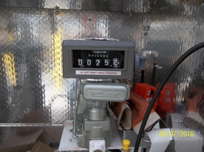
1 Basics of Proving LPG Meters Scott Simmons Colorado Division of Oil & Public Safety 1
2 Credits & Acknowledgements Many of the slides in this presentation were developed by the National Institute of Standards and Technology (NIST) for their LP-Gas Liquid Measuring Systems Course, and adapted for use in this presentation by Scott Simmons, Colorado Division of Oil and Public Safety. Permission was obtained from NIST for their use and adaptation. 2
3 Liquefied Petroleum Gas Safety
4 The Importance of Safety Safety is EXTREMELY IMPORTANT This section is one of the most critical in the course Cannot be over-stressed If you don t learn anything else learn that safety comes first Unsafe practices can harm not only yourself, but also others 4
5 Hazards of Testing LPG Devices Certain hazards associated with LPG, however Systems are designed in accordance with strict codes and requirements People who operate these systems should be trained for safe operation & response But you sometimes find they aren t trained You need to be prepared in case they are not! Likelihood of an accident testing LPG is no greater than when testing any other device type The consequences are much more serious 5
6 Protecting Yourself & Others Best protection is knowing safety precautions Knowledge will be acquired through: Study Classroom Field training Observation Safe practices ** The most important tool is your knowledge! ** 6
7 Protecting Yourself (cont.) You must KNOW: 1) Physical & chemical properties of substances you are dealing with 2) How test equipment and metering system work 3) What to expect under various conditions 4) How to identify and avoid development of dangerous situations 5) How to respond in case of emergency to protect: Yourself Those around you The general public 7
8 Properties & Hazards of LPG Properties which make LPG desirable are also those that account for hazards associated with it! 1) Boiling points Below normal atmospheric pressure and temperature - 44 o F for propane +32 o F for butane 2) Propane boils instantly when exposed to atmosphere (as does butane) LPG is liquid under pressure at ambient temperatures! 8
9 Properties & Hazards of LPG (cont.) 270 3) Recall 270:1 ratio economically desirable but can be a hazard if released uncontrolled into atmosphere 1 Liquid State Gaseous State 4) Propane Boils in Vicinity of Leaks refrigerant effect causes freeze burns on contact protective goggles and gauntlet gloves are a must! 9
 5) Flammability LPG is under pressure Release may be rapid and hard to")

10 Properties & Hazards of LPG (cont.) 5) Flammability LPG is under pressure Release may be rapid and hard to control High concentration of flammable gas Relatively narrow limits of flammability in air: Propane = 2.2% to 9.6% Anything less than 2.2% or greater than 9.6% concentration will not burn Butane = 1.9% to 8.6% 10
11 Properties & Hazards of LPG (cont.) 5) Flammability (cont.) Narrow limits of flammability contributes to safety of LPG products However, possibility of ignition is not remote Treat any release of product as potentially dangerous 6) Both Propane and Butane Are Heavier Than Air 7) Odorless Odorant such as ethyl mercaptan is added for detection Learn to recognize 11
12 Rupture of Storage Tank -- What Happens?? Explosive release of vapor Under normal conditions, pressure relief valves operate Vent excess vapor Little danger of happening spontaneously due To construction of tanks But there are other conditions that may threaten structural integrity of tank... 12
13 Conditions Threatening Structural Integrity 1) If Direct Flame on Liquid Area of Tank As long as no leaks occur, have no immediate danger of ignition As liquid is heated, product vaporization occurs As product vaporizes, pressure in tank increases NOW have a threat to the structural integrity of the tank Pressure relief valves should operate Controlled venting to atmosphere returns tank to safe pressure Valves close again automatically when pressure is reduced 13
14 Conditions Threatening Structural Integrity (cont.) 2) If Direct Flame on Vapor Space No liquid to cool metal of tank Rapid loss of integrity Temperature increases in a small area of tank shell RUPTURE of tank is often violent 14
15 BLEVE If the storage tank ruptures, it is called a Boiling Liquid Expanding Vapor Explosion or BLEVE 15
16 What to Do?? IF EVER IN DANGER OF RUPTURE, CLEAR AREA IMMEDIATELY! Fire is primary hazard Threatens structural integrity of tank Ignition of clouds is very similar to explosion Secondary ignition can occur if the fuel supply is not shut off First priority is to COOL TANK 16
17 What to Do?? (cont.) Extinguish fire ONLY AFTER FUEL SUPPLY IS CONTROLLED otherwise, re-ignition is possible When flame burns, it burns off vapor as it is emitted from tank If flame is extinguished, but leak still exists, vapors concentrate & can reignite 17
18 Emergency Equipment-- What YOU Must Have! Good idea to keep a checklist with you Highly recommended to keep a checklist with the prover A list of some absolutely essential equipment... 18
19 Essential Equipment Overview 1) Fire Extinguisher 2) First Aid Kit 3) Protective Gloves with Gauntlets 4) Protective Goggles 5) Caution Signs 6) Safety Cones 7) Phone Numbers for Emergencies 8) Continuous Supply of Water for Cooling Tank **Other Items Required by Jurisdiction/Co.??? ** 19
20 Essential Equipment 1) Fire Extinguisher 18 B:C dry chemical Should be the FIRST THING YOU SET out---don t leave it hooked inside the prover!!! 2) First aid kit Appropriate for inspecting LPG meters Safety officer/local OSHA rep 20
21 Essential Equipment (cont.) 3) Protective Gloves with Gauntlets should be worn at all times 4) Protective Goggles especially important when working around LPG 5) Caution Signs 6) Safety Cones 7) Phone Numbers for Emergencies Good idea to put on a card and keep in prover 8) Continuous Supply of Water for Cooling Tank Used to cool storage tank *** Other Items Required by Jurisdiction/Co.???*** 21


22 Make Safety a Habit!!! Observe safety rules at all times Includes use and maintenance of equipment Enhance knowledge of the operation and design of metering and testing equipment Learn to always anticipate conditions use common sense & good judgment!! 22
23 Safety Musts 1) No smoking within 100 feet recommended if an employee refuses to cooperate, stop examination and contact owner 2) Look out for leaks STOP EXAM until leaks are fixed 3) Report exposed/faulty wiring STOP EXAM until dangerous conditions are corrected 4) Never leave equipment unattended 23
24 Safety Musts (cont.) 5) Eliminate all possible sources of electrical discharge Includes clothing Synthetic clothing causes static Synthetic clothing melts at high temperatures; sticks to skin Results in serious burns Explosion-proof, non-sparking tools (incl. 2-way radios) 6) Chock prover Chock trailer or vehicle to avoid rolling/shifting Check again after prover is full of product 7) Ground prover Do NOT Cut Off Ground Prong of the Power Supply Electrical Wire! Ground prover to the system under test. 8) Regularly inspect prover hoses for wear and damage Consider establishing a regular replacement schedule 24
 9) Be sure all connections are tight BEFORE starting test 10) Never disconnect lines without bleeding vapor or liquid between connections always bleed off slowly don t get in a hurry!")
25 Safety Musts (cont.) 9) Be sure all connections are tight BEFORE starting test 10) Never disconnect lines without bleeding vapor or liquid between connections always bleed off slowly don t get in a hurry! 11) If any practice conducted by your jurisdiction is questionable, Contact Your Supervisor Immediately!! express your concerns **Other procedures Followed/Required by Your Jurisdiction** 25
26 Emergency Procedures Know What to Do!! When hazardous substances are contained, they do not pose a threat The potential for serious consequences if an accident occurs is very great Situations develop very rapidly, therefore, you should know safety procedures by heart 26
27 Know What to Do!! Firm personnel should be trained in responding to emergencies But don t count on it Be prepared yourself Owner/Operator of equipment is responsible for the safety of those who work with it If trained personnel are available to deal with an emergency, Stand By to Assist as Directed Since situations develop very quickly, you should be prepared to take appropriate action while waiting for assistance 27
28 How Can You Reduce the Risks? Ensure proper installation, operation, maintenance of: Metering equipment Your test equipment Keep product contained in system Maintain product at normal temperatures and pressures Consequences of an accident are of most concern Risk is reduced if you know how to react 28
29 The Fire Triangle Three elements are needed to start a fire: 1) Fuel 2) Oxygen (Air) 3) Ignition Source Need all three to have fire. 29

30 Figure 4-1: Fire Triangle Source: 30
31 What to Do If.. NOTE: These are steps that you should take: only if owner/operator or trained personnel are not able to respond OR if instructed to do so by trained personnel 31
32 What to Do If There is a Leak Leak, but no source of ignition: Primary concerns: you have two of the three elements required for a fire want to stop leak and prevent source of ignition 1) Stop leak (if possible) 2) Summon help if needed 3) Turn off all pumps, motors, and any other ignition sources 32
33 What to Do If There is a Leak 4) Look to see where vapor is likely to settle: does this pose a hazard how can it be resolved warn people away from area 5) Stay on upwind side of system 6) Yield control to emergency personnel when they arrive everyone not assisting kept at least 200 feet away 7) Water sprayed across the path of the vapor cloud 33
34 What to Do If There is a Leak 8) If you cannot stop the leak warn people away watch for sources of ignition maintain flow of water across the vapor path 9) Do not under any circumstances attempt to move equipment or take other action unless instructed by qualified personnel!! 34
35 What to Do If There is a Fire This is much more critical depends on the proximity of the fire to the tank These steps are in addition to the above measures First determine: Does the fire pose immediate threat to the tank or the prover s structural integrity? 35
36 Fire Does Not Pose a Threat to Tank If fire is sufficiently far away from the tank: first priority: extinguish the fire if source of fire is electrical, shut off power supply if fire is small, put it out with dry chemicals Never use water on electrical fire unless you are absolutely sure power is off!! if source of fire is solid material, use water Never use water on a petroleum or flammable liquid fire!!! 36
37 Fire Does Threaten Integrity first priority: cool the tank spray all sides of tank with water--this will cool tank and reduce tank pressure spray water on all sides of upper part of tank (vapor space); this will cool the vapor space lower part (liquid space) is cooled by the refrigerant effect of the liquid and the water draining down the tank s sides 37
38 Fire Does Threaten Integrity (cont.) If pressure relief valve is ignited: direct water away from it, but do not extinguish the flame if flame is extinguished you can get a secondary ignition which can be more serious 38
39 Fire Does Threaten Integrity (cont.) If external material is the source of the fire: cooling of tank is still the first priority, especially cooling the vapor space If possible: move the source of flame from the tank OR move the tank from the source of the flame Remember: COOLING OF TANK IS ALWAYS THE FIRST PRIORITY If tank ruptures, this can lead to a catastrophic situation!! 39
40 Liquefied Petroleum Gas The Nature of LPG Products, Their Storage, Measurement, and Delivery
41 Liquefied Petroleum Gas Composition: Propane Propylene Butanes Butylenes Commercial LPG is not a pure product: Propane and other components such as ethane Generally more than 90% propane Up to 7% - 8% ethane 41


42 Use and Value of LPG Stored in liquid state and used in gaseous state Especially high in rural areas and in agricultural applications Also used for Heating Motor fuel Industrial applications LPG is sold by weight or volume 42
43 Important Properties of LPG Gases at atmospheric temperature and pressure Easily liquefied for storage & transportation Takes up less space when in liquid than in gaseous form Easily reconverted back to gaseous state for use By returning to atmospheric temperature and pressure No special equipment required Cost of liquefication & special storage equipment outweighed by advantages 43
44 Comparison of LPG Volume in Liquid vs. Gaseous States Liquid State Gaseous State 44
45 Liquefying of Gases To be liquefied a substance must be maintained at a temperature below its boiling point 45


46 Liquefying of LPG Liquefied by refrigeration Maintained by pressurization Containers fabricated to withstand several times the vapor pressure of propane within the normal temp range 46
47 Considerations for Dispensing LPG Liquid State Very Important Especially since a particular amount of gaseous propane occupies approximately 270 times the same volume as it would in liquid form Vapor in liquid can result in inaccurate measurement Just like other liquid-measuring devices, do not want product and vapor passing through meter 47

 Heating/cooling product to")


48 Commercial Transactions Often based upon the volume sold at a standard reference temperature of 60 o F (or 15 o C) Heating/cooling product to 60 o F (or 15 o C) is not practical for commercial applications Corrections are usually made Use temperature compensator Use correction tables 48
 pressures Pressures")

49 Some Requirements for an LPG System Closed system No leakage Capable of withstanding established (high) pressures Pressures established by ASME (American Society of Mechanical Engineers) Pressure relief valves Permits controlled venting when pressure builds 49
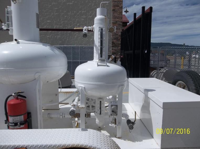
50 Basic Components of an LPG System Four Basic Components: 1) Storage Tank 2) Pump 3) Metering Unit 4) Piping Connecting Other Components Let s Take a Closer Look at the Components.. 50
51 Figure 2-1: Basic Components of Delivery System 51

52 Basic Components - Storage Tank Includes: Liquid fill inlet Discharge outlet Vapor port for pressure equalization during filling or meter testing 52
53 Components of the Metering Unit The Metering Unit: Meter Indicating Element Driven directly by the measuring unit Last two components of metering unit prevent vapor from passing through the meter.. 53

54 Components of the Metering Unit The Metering Unit: Meter Indicating Element Driven directly by the measuring unit 54
 Vapor Eliminator Separates vapor from liquid prior to meter")
55 Components of the Metering Unit (cont.) Vapor Eliminator Separates vapor from liquid prior to meter Returns vapor to storage tank 55
 Differential Pressure Valve Keeps pressure")

56 Components of the Metering Unit (cont.) Differential Pressure Valve Keeps pressure constant Help maintain product in a liquid state Even small pressure differentials can result in some vaporization 56
57 Receiving Tanks & Delivery of Product Product Delivery: Liquid goes into receiving tank Displaces vapor in receiving tank Pressure in receiving tank increases Pressure increases cause vapor in tank to condense to liquid Equilibrium is eventually restored, but NOT INSTANTANEOUSLY 57
58 Design of Receiving Tanks Older Designs Got around this by hooking up a vapor line Between the vapor spaces of the delivering tank and the receiving tank This maintains the equilibrium However, this is not always equitable Some product in the form of vapor is returned to the seller 58
59 Design of Tanks Newer Design - Spray Fill Spray enters tank, spray cools vapor space Promotes condensation (Remember.A decrease in temperature means less pressure is required for product to go to liquid state) Causes a reduction of pressure in the tank As a result of pressure reduction, tank is easier to fill Most tanks are like this now 59

60 Figure 2-3 Spray-Fill Design 60
61 Figure 3-1: The Intake Line 61


62 Figure 3-2: Typical Pump Designs Sliding-Vane Pump Regenerative Turbine Pump Gear Pump 62
63 Pump Operation As pump displaces product through outlet, lower pressure is momentarily created at the inlet Rate of displacement is a function of: Pump speed and design, Size of the piping at the outlet Pressure of vapor in the storage tank pushes liquid into intake line 63
64 Pump Speed Can be a critical element in measurement accuracy If too high, pressure at the inlet falls below the vapor pressure of the product Causes some vaporization Technical term for this vaporization is cavitation or also called flashing Cavitation or flashing is the sudden formation and collapsing of bubbles in the liquid product Cavitation results in some degree of overregistration of the amount delivered 64
65 Overregistration vs. Overregistration Underregistration The metering system indicates over or more than the amount of product that has actually gone through the meter. Described as a minus or - error. The customer receives less than the indicated amount. Underregistration The metering system indicates under or less than the amount of product that has actually gone through the meter. Described as a plus or + error. The customer receives more product than the indicated amount. 65
66 Reducing Cavitation Suitable length of piping Proper fittings Proper size and operating speed of pump 66
67 Figure 3-3: Pump Internal Bypass Circuit Closing Valve 67
68 Pump Internal Bypass Circuit -- Function Prevents damage to pump when pump is in operation, but no product is being dispensed Is built into the pump itself Spring loaded Pressure inside pump rises as flow is restricted Pressure reaches predetermined amount and opens bypass valve Valve drops when flow resumes and puts pressure on valve PROBLEM: Friction from the product circulating in the internal bypass circuit causes product to heat. This results in some vaporization. 68
69 Figure 3-4: Pump External Bypass Circuit 69
70 External Automatic Bypass Valve - Example 70
71 External Bypass Valve--Functions Recommended by most manufacturers Product recirculated through storage tank where vapor rises to the vapor space Allows fresh product to be circulated to pump External bypass valve is set to open at a pressure of: Approximately psi lower than the internal bypass valve Also has manual control For purging & cleaning lines 71
72 Other System Components Excess Flow Valve Shuts off flow in event of hose/line rupture Set to allow flow at normal flow rates Closes automatically when normal flow rate is exceeded Re-opens automatically when flow returns to normal Pressure Gauges Warns of pressure build-up Enables monitoring of pressure for proper operation 72
73 Figure 3-5: Hydrostatic Pressure Relief Valve 73
74 Other System Components (cont.) Hydrostatic Pressure Relief Valves Perform crucial safety function Placed between two shut-off valves They must be at every place this occurs in system where LPG is contained or trapped Set to open at a certain critical pressure If temperature rises from sun or high heat and pressure increases, they open to release pressure from expanding product 74
75 Location of Pressure Relief Valves (& Shut Off Valves) in System (from Fig 3-1) 75
76 Figure 3-6: Typical Vapor Eliminator 76
77 Vapor Eliminator -- Functions Removes vapor prior to the meter Last line of defense against vapor caused by restrictions, etc. Basic operation Float in chamber of air eliminator Liquid flows into chamber and vapor bubbles rise to the surface When float drops below a certain level, valve opens to vent vapor Vapor carried back to vapor space of storage tank As vapor is removed, level of liquid flowing in rises, float rises, & valve closes Cycle begins again Entrained air very difficult to remove 77
78 Other System Components Strainers Trap solid contaminants Must be kept clean to avoid restrictions & vapor production Valves Service valves in lines Can be shut to close off sections of piping to work on lines or for emergencies Must also have pressure relief valves between two valves per NFPA codes Cannot be used to divert product Must be kept in full open position to avoid restricting flow 78

79 Figure 3-7: PD Meter Design - Example 1 NIST NIST LPG- LPG Course-Ch3-Operation-6-15-Rev2 Course-Ch4-Safety-6-15-Rev2
80 Figure 3-8: PD Meter Design - Example 2 NIST NIST LPG- LPG Course-Ch3-Operation-6-15-Rev2 Course-Ch4-Safety-6-15-Rev2
81 Positive Displacement Meters Liquid momentarily separated into segments of known volume Same number of segments pass through meter on each revolution Segments are rejoined after the meter and flow to the discharge line Fluid flow drives meter s moving parts Volume is determined from number of meter revolutions & the quantity per revolution 81
82 Meter Errors Simple design means relatively few causes of error Typical causes of errors: Presence of vapor in product Solid contaminants Widens clearances This is why strainer is important Small amounts of slippage Can be offset by meter adjustment to some extent Increased at low flow rates 82
83 Meter Adjustments Made through the register element Register counts the number of revolutions of the meter Can offset slippage at low flow rates Ineffective when meter is badly worn Adjustments can be mechanical or electronic 83
84 Figure 3-10: Mechanical Indicator 84
85 Mechanical Registers Wheel type: Series of wheels One wheel per digit Wheel segmented with numbers & lines Revolving meter shaft Gear train transfers revolution of meter to the indicating elements (to right-hand wheel) Right-hand wheel turns with meter shaft Each complete revolution of right-hand wheel increments next higher wheel Fixed indicator--pointer 85
86 Figure 3-11: Right Hand Indicating Wheel 86
87 Figure 3-12: Electronic Indicator 87
88 Electronic Indicators Fewer moving parts Often more features and information: Computing capability Multiple calibration points Data communication Mechanical motion of the shaft is transformed into a digital signal Accomplished by means of a pulser 88
89 Other Device Features - Reset Returns indications to zero (per H44) Knob on an analog Pushbutton on a digital Cannot display values during the reset operation if indications advance to zero Do not want readable values during reset Shutters or blanking are used 89
90 Mechanical Indicator Reset (from Figure 3-10) Reset Shutters drop to obscure indications during reset NIST NIST LPG- LPG Course-Ch3-Operation-6-15-Rev2 Course-Ch4-Safety-6-15-Rev2
91 Electronic Indicator Reset (From Figure 3-12) Reset Indications blank during reset operation NIST NIST LPG- LPG Course-Ch3-Operation-6-15-Rev2 Course-Ch4-Safety-6-15-Rev2
92 Other Device Features - Totalizers Totalizers keep track of total product Used for: Inventory control Detect theft & loss Testing 92
93 Meter Adjustments Through the Indicator Register is adjusted to bring the indication of the delivery as close as possible to a zero-error condition Excessively worn meter may not be capable of adjustment Adjustments through digital indicators: Performed electronically Calibration factors based on errors observed during testing Some have multiple point calibration 93
94 Meter Adjustments (cont.) Adjustments through mechanical indicators: Change gear mechanism in some models Rate of revolution is altered by changing gears Another design adjusts the speed of the output shaft to the register over a range May use a calibrated dial to accomplish this Mechanical adjustors are located between the meter and the register 94
95 Ticket Printer Required for all vehicle-mounted systems (UR.2.6) Requirement became retroactive in 1994 Driven directly by the register: Mechanically or Electronically Some have capability to print prices, tax, dates, etc. calculated by the register 95
96 Temperature Compensation LPG expands in volume by approximately 1% per every 5 F increase in temperature Manual or automatic temperature compensation Correct volume of product to 60 F Automatic temperature compensators (ATC s) Reduce manual errors Automatic adjustor Temperature sensed by a device installed in the meter or intake line Usually located between the meter and the register in the meter stack Usually equipped with some means for preventing it from being deactivated and should be sealed 96
97 Figure 3-20: The Meter Stack 97
98 Temp Compensation -- Method of Sale H44 does not require ATC, however. Uniform Method of Sale of Commodities Regulation, NIST Handbook 130: Requires sale of LPG based on 15 C or 60 F For metered sales by the gallon: For devices with a manufacturer s maximum rated capacity of more than 20 gallons per minute must have ATC 98
99 Uniform Method of Sale of Commodities Regulation Liquefied Petroleum Gas. - All liquefied petroleum gas, including but not limited to propane, butane, and mixtures thereof, shall be kept, offered, exposed for sale, or sold by the pound, metered cubic foot [See NOTE 7] of vapor (defined as 1 cu ft at 60 F), or the gallon (defined as 231 cu in at 60 F). All metered sales by the gallon, except those using meters with a maximum rated capacity of 20 gallons per minute or less, shall be accomplished by use of a meter and device that automatically compensates for temperature. (Added 1986) (NIST Handbook 130) 99
100 Figure 3-21: Differential Pressure Valve 2. Pressure Lower on Liquid Side of Valve 5. Pressure Rises Higher on Liquid Side of Valve 3. Valve Seats; Flow Stops 6. Valve Unseats; Flow Resumes 1.Pump Off 4.Pump On 100
101 The Discharge Line-- Differential Pressure Valve Located just ahead of the meter outlet Also known as the differential valve or differential backpressure valve Maintains back pressure Works on principle of balanced pressure Serves to maintain sufficient level of pressure upstream of meter Prevents pressure from being bled into the discharge line during periods of nonuse 101
102 Differential Pressure Valve (cont.) Helps minimize product vaporization Increases efficiency of air eliminator Automatic in design Example in Figure 3-19: Top chamber is connected to a vapor line running to vapor space of tank Bottom chamber is filled with liquid product that has passed through the meter 102
103 Differential Pressure Valve Basic Operation When pressure on the liquid side of the diaphragm is lower than or equal to the pressure of the vapor (and liquid) in the storage tank: A spring holds the valve closed Liquid product can not pass through to the discharge line When pump operates, pressure on liquid side of diaphragm will rise Diaphragm is forced up Valve is unseated and product flows through to discharge line Valve will close again when pressure of liquid is balanced with pressure in the tank 103
104 Discharge Line or Hose Carries metered product to the receiving tank Must be a wet hose system i.e., full of liquid at all times Shut-off valve at end to prevent hose from being drained Since liquid can be trapped between end shut-off valve and differential pressure valve, need a pressure relief valve between the two valves 104

105 Liquefied Petroleum Gas Meter Test and Equipment 105
106 Chapter 5 -- General Introduction Safe, accurate, and efficient proving is possible only if the inspector: has proper equipment, and is knowledgeable Quick Fix NOT ACCEPTABLE Hazardous nature of product -- don t take chances Create a potentially dangerous situation Wasting time of owner and jurisdiction Be prepared before you start! 106
107 General--Intro. (cont.) Inspector has primary responsibility for maintaining test equipment Prover is a field standard & is a precision device Neglect can render prover inaccurate Basic Equipment Set-up, use, and maintenance of equipment Will review & practice this in field training 107
108 Basic Equipment 1) One or more dry chemical B:C fire extinguishers 2) First aid kit 3) Protective goggles and gauntlet gloves 4) Caution signs, markers, safety cones 5) Calibrated field standard prover of correct capacity for type of metering & standard fittings 6) Heavy duty 3-wire, 100 extension cord (size 10 neoprene-covered) 7) Electrical receptacle wall plug AC ground tester 8) Grounding cable 108
109 Basic Equipment (cont.) 9) Complete set of adaptors for LPG fittings Suggested list in APPENDIX B 10) Matched & accurate liquid glass or digital thermometers: -30 o F to 130 o F 1 o F increments At least 12 in length Accurate to within +/- 0.5 o F At least 6 thermometers at all times Important to be matched 1 o F difference can result in as much as 40 cubic inches of error in readings 109
110 Basic Equipment (cont.) 11) Ethylene glycol, bulb syringe 12) Pipe joint compound 13) Hand tools and tool box 14) Stop watch 15) Temperature and pressure correction tables for prover 16) ASTM Table 24 for temperature corrections 17) NIST HB 44 and other applicable codes and regulations 18) Report forms 19) Lead and wire seals, tags, seals, etc. as needed 20) Equipment checklist and emergency numbers to keep with prover 110

 111")
111 Basic Equipment (cont.) 111
112 LPG Field Standard Prover -- General Largest and most expensive piece of equipment you are using Precision liquid measuring device Provides high degree of accuracy and reliability when correctly maintained and used 112
113 LPG Field Standard Prover Design & Operation Designed & constructed according to NIST OWM specifications NIST HB Modifications no longer permit bleeder valve OWM may reconsider this in future edition Should be calibrated and periodically re-certified according to NIST IR 7383 or procedures of your jurisdiction 113
114 LPG Field Standard Prover Design & Operation 114
115 Figure 5-1: LPG Prover & Metering System Components
116 LPG Liquid Prover -- Overview Three basic connections: 1) Liquid supply line from system tank to prover 2) Liquid return line from prover to system tank 3) Vapor return line from top of prover to top of vapor space of system tank Stationary or mounted on bed of a truck or trailer Must withstand working gauge pressures of at least 250 psi 116
117 Vapor Return Line Opened after liquid discharge & return lines are connected Closed before taking reading Allows vapor initially in prover to be pushed back into system tank If vapor in prover were to remain, pressure from incoming liquid would cause condensation Necessary for testing; not possible to determine amount of product resulting from vapor condensation Commercial transaction: vapor in the receiving tank belongs to customer Spray fill tank ( new ) design enables efficient delivery Promotes condensation Reduces pressure 117
118 LPG Liquid Prover-- Other Points Pump, Motor, and Hoses Must be suitable for use with LPG products All electrical connections must be Explosion-Proof Valves, fittings, gauges suitable for use with LPG Capacity Suitable for application Common sizes are 25-, 50-, &100-gallon 118
119 Figure 5-2: LPG Liquid Prover
120 LPG Prover Components 1) Body - spheroidal 2) Upper neck gauge 3) Lower neck gauge Monitor for product level For zeroing prover 4) Strainer Traps contaminants Cleaned regularly 5) Pump bypass circuit Protects pump Set to open when pressure at the pump outlet is too high e.g., Between end of delivery & when the pump is turned off 120
121 LPG Prover Components (cont.) 6) Thermometer well Temperature of liquid to make temperature corrections Expansion of prover shell dependent upon shell material 7) Pressure gauges To make pressure corrections Every prover responds differently to pressurization Each prover has its own unique pressure correction table! 8) Leveling shelves 9) Bleed line and bleeder valve To bleed small quantities of product when zeroing prover 121
122 Figures 5-3 & 5-5: Prover Gauge and Scale Assembly and Seals
123 Scale Plates Mounted on adjustable brackets Sealed in position with wire seals Decimal gallon readings are used in calculations Converted to cubic inches later, if needed Smallest graduated interval 0.05 gallons on a 100-gallon prover 0.02 gallons on a 50-gallon prover 0.01 gallons on a 20-gallon prover 123
124 Scale Plates - Range Range should be no less than 4% of the nominal capacity of the prover Graduated both above and below by not less than 1.5% of the nominal capacity Example of a 100-gallon prover: 100 gallon prover Range of entire scale no less than 4% = 4 gallons Graduations above and below no less than 1.5% = 1.5 gallons 124
125 Reading the Prover-- The Meniscus Capillary action of glass tube results in meniscus Prover is read at eye level, reading the bottom of the meniscus 125
126 Figure 5-4: Reading the Prover Gauge
127 Setting Up the Prover-- Notes Several of these steps should be performed by the operator, not the inspector Require operator to stand by during test since he is most familiar with equipment being tested If inspector may be held responsible for any resulting damage if operating equipment or making connections 127
128 Setting Up the Prover-- Procedures Remember: Safety First!!! Position the prover: Away from source of ignition On stable surface Near power source Confirm the power source is grounded Be sure prover return pump operates before pumping product into the prover Location should enable you to see meter, register, & prover indications as you operate the prover valves Position fire extinguishers within easy reach Do Not Leave Them in the Prover!! 128
129 Set-Up Procedures (cont.) Chock and level prover trailer or vehicle Check chocks and level again with product in the prover Position warning signs and safety cones Ground the prover to a suitable ground Check fittings for adaptors required before proceeding Note and record totalizer Inspect temperature wells for dirt and debris Clean & fill Check prover & bleed valves Be sure they are closed tight 129

130 Set-Up Procedures (cont.) 130
131 Set-Up Procedures (cont.) Have operator: Connect the system delivery hose to prover inlet line Connect vapor return line to system vapor connection Connect prover liquid return line to system liquid inlet Check for tight connections; valves & bleeders are closed Open vapor return line valves SLOWLY to avoid abrupt pressurization of prover Observe pressure gauges Install thermometers in (meter) and prover 131

132 Set-Up Procedures (cont.) 132
133 Why Wet the Prover? LPG provers are CALIBRATED TO DELIVER Contain slightly more than their rated capacity when full Have clingage on sides Impractical to remove clingage between test drafts Will use a drain period of 30 seconds during testing Duplicates prover calibration 133
134 What Does Wetting the Prover Accomplish? Must wet prover for each meter Wets inside of prover Forces evacuation of left-over vapor Brings temperature of prover to that of the liquid 134
135 Wetting The Prover -- An Unofficial Test Not an official test Still record pressure readings The cause of divergent pressure readings must be remedied before proceeding Usually restriction in vapor line from undersized hose Significant divergence will invalidate test results 135
136 Wetting the Prover 1) Have operator activate and engage the system pump 2) Open the prover inlet valve SLOWLY 3) As liquid fills prover, note pressure readings Balanced condition must be maintained Cause of more than about 5 psi divergence must be corrected before proceeding 4) Close prover liquid inlet valve when product reaches capacity line in neck gauge 136


137 Wetting the Prover (cont.) 137
138 Wetting the Prover (cont.) 5) Have the operator disengage the system pump 6) With prover full of liquid: Level prover Raise bed so vehicle wheels are not resting on ground Check chocks on trailer or prover to prevent shifting 7) Open prover liquid return line valve SLOWLY 8) Start prover return pump 138


139 Wetting the Prover (cont.) 139
140 Wetting the Prover (cont.) 9) Monitor lower neck gauge level When liquid level appears in the top of the lower sight gauge, QUICKLY CLOSE LIQUID RETURN LINE 10) Start stopwatch 11) Turn off prover pump 12) During 30-second drain, ZERO the Liquid Level in the Lower Neck Gauge If above zero line, use bleed valve in liquid inlet line to bleed off excess Have operator start pump and add additional product if below zero line 140
141 Test Drafts Similar to wetting prover Require at least three or more drafts Before beginning delivery: Check for correct zero on prover Slightly above zero is okay Slightly below, re-zero Have operator start pump Reset register indications 141
142 During Delivery Monitor pressure gauges Change of more than 5 psi from initial, halt test & start over Change in pressure may cause condensation--invalidates test results Monitor Flow rate Start timing at 10 gallons Make sure you are operating within rated minimum and maximum flow rates of device 142
143 During Delivery (cont.) Except for temperature compensated runs, note & record temperature readings at the meter at 1/3 & 2/3 of prover capacity Close prover inlet valve to stop delivery (meter indication) at even gallon or as soon as possible after liquid appears in the upper neck gauge Convenient (but not necessary) to stop meter indication at prover capacity 143
144 After Delivery 1) Close vapor return line to fix temperature and pressure inside of prover 2) Have the operator turn off the system pump 3) Record prover pressure and temperature 4) Recheck level and record meter & prover readings Wait until bubbles subside before taking a reading 144


145 145
 Bubbles indicate a pressure differential exists May be necessary to flush prover one or more times to reduce differential 5) Open vapor")
146 After Delivery (cont.) 4) (cont.) Bubbles indicate a pressure differential exists May be necessary to flush prover one or more times to reduce differential 5) Open vapor return line 6) Return product to the delivery system Observe correct drain procedure & 30-second drain period 146
147 Prover Maintenance -- General Note & report immediately to your supervisor: Any damage which has occurred to prover Abnormal performance, especially leaks Repairs to be made only by qualified personnel Have prover recalibrated if necessary following repairs Should have a regular re-inspection/recalibration program for your prover 147
148 Prover Maintenance Following Each Use Bleed vapor and liquid lines if they are to be removed Not necessary with hard-mounted lines Do only in area where there is no danger of ignition LPG is heavier than air; always direct venting of vapor in an upward direction Dissipates to prevent collection of dangerous vapors Store hoses carefully and avoid crimping Clean dirt from fittings (do not drag on ground!) Cap all connections on prover 148

149 Prover Maintenance Following Each Use 149
150 Prover Maintenance (cont.) Cover thermometer well NEVER leave thermometer in well while transporting prover Clean & store thermometers carefully Check & clean strainer in liquid return line regularly DO NOT bleed prover to atmospheric pressure Water-laden air may enter prover and condense--causes rusting and corrosion Follow manufacturer s instructions for lubricating pump, return valves 150
151 Questions? Scott Simmons Colorado Division of Oil & Public Safety (303)
2015 NIST EPO No. 26
 2015 NIST EPO No. 26 Examination Procedure Outline for Liquefied Petroleum Gas (LPG) Liquid-Measuring Systems It is recommended that this outline be followed as minimum criteria for examining all LPG liquid-measuring
Emergency Water Injection /28/2017 updated 07/21/2017
 Emergency Water Injection 101 06/28/2017 updated 07/21/2017 Written By: Ronald D. Huffman, www.respondertraining.com When something happens and you're faced with an uncontrollable liquid propane leak you
AIR-OPERATED DOUBLE DIAPHRAGM PUMP USER S MANUAL
 00, 0, 000 00, 000, 00 A. TECHNICAL INFORMATION Model 00 Inlet/Outlet " Air Inlet /" 0 / 000 /" /" 00 /" /" 000 /" /" 00 /" /" Flow Rate GPM/ 0LPM GPM/ 0LPM GPM/ LPM GPM/ LPM GPM/ 0LPM GPM/ 0LPM Maximum
TECHNICAL DATA MAINTENANCE AIR COMPRESSOR MODEL G-1
 Dry 131h 1. DESCRIPTION The Viking Model G-1 Maintenance Air Compressor is an electric motor-driven, aircooled, single-stage, oil-less compressor. The unit is equipped with a check valve and provides a
API MPMS Chapter 17.6 Guidelines for Determining the Fullness of Pipelines between Vessels and Shore Tanks
 API MPMS Chapter 17.6 Guidelines for Determining the Fullness of Pipelines between Vessels and Shore Tanks 1. Scope This document describes procedures for determining or confirming the fill condition of
Scorched Nuts Fire Art Guide
 Scorched Nuts Fire Art Guide This guide is to serve as a reference for the construction and use of flame effects while at Scorched Nuts. At this time, no pressurized effects(poofers) will be permitted
Type , , S2.20 Specialized test procedure Procedure for testing LPG bulk meters using a vapour displacement prover
 Field Inspection Manual Part: 4-STP Section: 26 Page: 1 of 14 Type 52.11-13, 52.21-23, S2.20 Specialized test procedure Procedure for testing LPG bulk meters Application This test is applied to LPG bulk
Chapter 4. Preliminaries to the Field Examination. Test Equipment, Safety Procedures
 Chapter 4 Preliminaries to the Field Examination Test Equipment, Safety Procedures Chapter Objectives Upon completion of this chapter, you should be able to: 1. Identify test equipment used in field examinations
Compiled by: B Beard. Approved by: SH Carstens. Description of requirements and procedures for compact provers to be used as verification standards.
 1. Scope Description of requirements and procedures for compact provers to be used as verification standards. 2. Reference documents Trade Metrology Act SANS1698 3. Policy A. BASIC REQUIREMENTS Compact
WARNING: FOR OUTDOOR USE ONLY
 Certified to CSA International 4.96 US For Outdoor Gas Fireplaces A HIGHER STANDARD IN QUALITY AND APPEARANCE SAFE AND BEAUTIFUL OUTDOOR LARGO FIRE PIT FOR PROPANE AND *NATURAL GAS OWNER S MANUAL WARNING:
Responding to Natural Gas Pipeline Emergencies
 Responding to Natural Gas Pipeline Emergencies Who is Florida Gas Transmission? Florida Gas Transmission operates nearly 5,000-miles of interstate natural gas transmission pipelines, a system that extends
SAFETY MANUAL FOR FLAMMABLE PRODUCT TRANSFER
 SAFETY MANUAL FOR FLAMMABLE PRODUCT TRANSFER SUPPLIMENT TO eom IMPORTANT READ THIS MANUAL BEFORE PRODUCT INSTALLATION, OPERATION, INSPECTION & MAINTENANCE Tougher and more rigid guidelines are being established
FLAMMABLE GASES AND FLAMMABLE CRYOGENIC FLUIDS
 CHAPTER 35 FLAMMABLE GASES AND FLAMMABLE CRYOGENIC FLUIDS SECTION 3501 GENERAL 3501.1 Scope. The storage and use of flammable gases shall be in accordance with this chapter. Compressed gases shall also
HOT OILING OPERATIONS ALL HSE PRC 172. Approved By: Manager, HSE Performance Assurance. Table of Contents
 Owner: HSE Performance Assurance ALL HSE PRC 172 Approved By: Manager, HSE Performance Assurance Retention Code: CG01 CA Revised: March 2015 Review Frequency: Five years or less Table of Contents 1.0 Purpose...
3 GALLON, OILLESS PANCAKE COMPRESSOR INSTRUCTIONS. Item #31289
 3 GALLON, OILLESS PANCAKE COMPRESSOR INSTRUCTIONS Item #31289 The EASTWOOD 3 GALLON, OILLESS PANCAKE COMPRESSOR, with an Integral Air Regulator, efficiently supplies all compressed air requirements for
OPERATION MANUAL NTF-60 Plus
 OPERATION MANUAL NTF-60 Plus Nitrogen Tire Filling Valve Stem Caps (Qty=200) Order P/N 436075 RTI Technologies, Inc 10 Innovation Drive York, PA 17402 800-468-2321 www.rtitech.com 035-81264-00 (Rev A)
U.S. CONCRETE, INC. SAFETY POLICY and PROCEDURE MANUAL
 SAFE -14 Page 1 of 8 U.S. CONCRETE, INC. SAFETY POLICY and PROCEDURE MANUAL FUNCTION Safety TOPIC Hotwork Permit Program OBJECTIVE(S): GENERAL POLICY: To provide a work atmosphere that is conducive to
Spirax Compact FREME Flash Recovery Energy Management Equipment
 IM-UK-cFREME UK Issue 1 Spirax Compact FREME Flash Recovery Energy Management Equipment Installation and Maintenance Instructions 1. Safety information 2. General product information 3. Installation 4.
Portable Oil Lube Air Compressors
 Portable Oil Lube Air Compressors 8003631 8003632 0410149 8018968 8018940 Owner s Manual Read and understand operating instructions before use Safety definitions The information listed below should be
AIR COMPRESSOR OPERATING INSTRUCTION AND PARTS LIST
 AIR COMPRESSOR OPERATING INSTRUCTION AND PARTS LIST OIL-LESS TYPE IMPORTANT: PLEASE READ CAREFULLY BEFORE STARTING OPERATIONS. THE CONTENTS ARE FOR GENERAL INFORMATION OF ALL THE SIMILAR MODELS. Record
TECHNICAL DATA. Low-Flow Foam Preaction System with Hydraulically Actuated Concentrate Control Valve.
 Foam 302 a 1. DESCRIPTION (Refer to Figure 1 on page 302 e.) The Viking Low-Flow Foam/Water Proportioning System is a UL Listed and FM Approved system, for use with 3M and Viking brand foam concentrate.
Handling and Storage of Gases
 Handling and Storage of Gases Learning Outcome When you complete this module you will be able to: Describe the procedures for safe storage and handling of cylinders containing gases. Learning Objectives
CITY AND COUNTY OF DENVER CR&CF RISK UNIT Compressed Gas Safety Standard
 CITY AND COUNTY OF DENVER CR&CF RISK UNIT 65.5.11 Compressed Gas Safety Standard 1.0 Introduction 2.0 Scope This standard has been developed to protect all City and County of Denver employees and contractors
LPG DRIVER ATTENDED TRANSPORT LOADING
 November 1993 Prepared By: Ken A. Steward. P.E. Linco-Electromatic, Inc. 4580 West Wall Street Midland, Texas 78703 LPG DRIVER ATTENDED TRANSPORT LOADING INTRODUCTION The safest and most accurate method
Vehicle- or rack-mounted liquefied gas meters, pump supplied
 Purpose This inspection procedure outline (IPO) defines the minimum tests which must be performed to ensure that basic volumetric measuring devices comply with the legislation. Application Rack/fixed metering
R E D I C O N T R O L S
 R E D I C O N T R O L S Operation & Maintenance Manual Portable Service Purger for Low Pressure Chillers Model: PSP-LP-1B For Refrigerants R-11, R-113, R-114 & R-123 & Other Similar Refrigerants File Literature
LPG TANK INFORMATION An energy company that puts
 LPG TANK INFORMATION An energy company that puts Safety first. LPG TANKS Thanks Thank you for choosing Kleenheat for your LPG supply. We consider safety our number one priority, so please make time to
Data Sheet Issue A
 Features 1. Differential latching clappertype, lighweight, dependable construction. 2. Low Air Pressurized System, 8 psi -to- 26 psi (0,6 bar to- 1,8 bar) 3. Reset externally. Cover removal is not required.
DESIGN DATA A WET PIPE BLADDER TANK FOAM/WATER SYSTEM WITH HYDRAULICALLY ACTUATED DELUGE CONCENTRATE CONTROL VALVE
 February 9, 1998 Foam 101a A BLADDER TANK WITH 1. DESCRIPTION A Wet Pipe Bladder Tank Foam/Water System is a standard wet pipe automatic sprinkler system capable of discharging a foam/water solution automatically
TECHNICAL DATA. than the water inlet pressure to the concentrate
 Foam102a 1. DESCRIPTION The Viking Low Flow Foam/Water proportioning system, is a UL Listed and FM Approved system, for use with 3M foam concentrates. This system consists of a standard wet pipe sprinkler
Copyright, 2005 GPM Hydraulic Consulting, Inc.
 Troubleshooting and Preventive Maintenance of Hydraulic Systems Learning to Read the Signs of Future System Failures Instructed by: Al Smiley & Alan Dellinger Copyright, 2005 GPM Hydraulic Consulting,
MODEL NUMBER: PSI AIR SOURCE KIT 200 PSI Compressor on 2.0 Gallon 200 PSI Air Tank
 IMPORTANT SAFETY INSTRUCTIONS CAUTION - To reduce risk of electrical shock or Electrocution: MODEL NUMBER: 20008 200 PSI AIR SOURCE KIT 200 PSI Compressor on 2.0 Gallon 200 PSI Air Tank IMPORTANT: It is
Hotspotter. Model WB-100 Professional Series. Assembly, Testing & Operating Instructions. Safety Information:
 Hotspotter Model WB-100 Professional Series Assembly, Testing & Safety Information: Safety publications related to safe practice and use: CSA 2-94 U.S. Requirements for Hand-Held LP Torches for use with
L 100. Bubble-Tube Level System. Installation, Operation and Maintenance Instructions
 L 100 Bubble-Tube Level System Installation, Operation and Maintenance Instructions Figure 1 Contents Section Description Page 1.0 Introduction 2 2.0 Specifications 3 3.0 Installation 3 4.0 Warranty 6
OPERATION MANUAL NTF-15
 OPERATION MANUAL NTF-15 Nitrogen Tire Filling Valve Stem Caps (Qty=200) Order P/N 436075 RTI Technologies, Inc 10 Innovation Drive York, PA 17402 800-468-2321 www.rtitech.com 035-81235-00 (Rev B) TABLE
Model: 43T. Bermad Pressure Relief Valve
 Model: 43T Bermad Pressure Relief Valve Installation Operation Maintenance Manual () Rev.C1_01.08.17 Page 1 of 10 Safety First BERMAD believes that the safety of personnel working with and around our equipment
CNG/LPG Vehicles Emergency First Response Guide
 CNG/LPG Vehicles Emergency First Response Guide TABLE OF CONTENTS Introduction... 1 In Case of Fire... 1 Safety Information... 2 Identifying a CNG/LPG Vehicle... 2-3 CNG Safety... 4 LPG Safety... 5 IMPCO
Installation, Operation & Maintenance Manual for Flo-Max Coupler Bracket Model FM150
 Installation, Operation & Maintenance Manual for Flo-Max Coupler Bracket Model FM150 January 2013 Form FVC 084 - Rev 02 IMPORTANT: KEEP THIS DOCUMENT WITH THE PRODUCT UNTIL IT REACHES THE END USER. 1.
ISO INTERNATIONAL STANDARD. Small craft Liquefied petroleum gas (LPG) systems
 systems") INTERNATIONAL STANDARD ISO 10239 Second edition 2008-02-15 Small craft Liquefied petroleum gas (LPG) systems Petits navires Installations alimentées en gaz de pétrole liquéfiés (GPL) Reference number ISO
INTERNATIONAL STANDARD ISO 10239 Second edition 2008-02-15 Small craft Liquefied petroleum gas (LPG) systems Petits navires Installations alimentées en gaz de pétrole liquéfiés (GPL) Reference number ISO
Assembly Drawing: W-311B-A01, or as applicable Parts List: W-311B-A01-1, or as applicable Special Tools: , , &
 REDQ Regulators Model 411B Barstock Design Powreactor Dome Regulator OPERATION AND MAINTENANCE Contents Scope..............................1 Installation..........................1 General Description....................1
MODEL NUMBER: P-A AUTOMATIC PORTABLE COMPRESSOR
 MODEL NUMBER: 45043-450P-A AUTOMATIC PORTABLE COMPRESSOR IMPORTANT: It is essential that you and any other operator of the product read and understand the contents of this manual before installing and
TECHNICAL DATA Q= C. Table 1 - Specifications
 September 25, 2013 Pressure Regulation 537a 1. Description The Model B-3 Pilot Operated Pressure Control Valve is a factory assembled unit. The unit consists of a Model J-2 Halar coated Flow Control Valve,
Hi-Force Limited Prospect Way Daventry Northants NN11 8PL United Kingdom Tel: +44(0) : Fax: +44(0) : Website:
 : Fax: +44(0) : Website:") 1.0 Inspection of the product upon receipt: On receipt of the product, visually inspect the item for any evidence of shipping damage. Please note shipping damage is not covered by warranty. If shipping
1.0 Inspection of the product upon receipt: On receipt of the product, visually inspect the item for any evidence of shipping damage. Please note shipping damage is not covered by warranty. If shipping
Bermad Pressure Reducing. Model: 42T
 Bermad Pressure Reducing Pilot Operated Pressure Control Valve Model: 42T Installation Operation Maintenance Manual (IOM) REV. 27.7.17 Page 1 of 12 Safety First BERMAD believes that the safety of personnel
DESIGN DATA OBSOLETE. C. Inspections - It is imperative that the system be inspected and tested on a regular basis. See Inspection
 February 9, 1998 Foam 201a 1. DESCRIPTION A Deluge Bladder Tank Foam/Water System is a standard deluge system capable of discharging a foam/water solution automatically through open sprinklers, spray nozzles,
Compressed Gas Cylinders - Guideline
 Environmental Health and Safety Compressed Gas Cylinders - Guideline Date of Issuance: 1/10/18 Revision Number: Initial Revision Date: Prepared by: EH&S 1. Purpose Carnegie Mellon University has developed
The Discussion of this exercise covers the following points:
 Exercise 5-3 Wet Reference Leg EXERCISE OBJECTIVE Learn to measure the level in a vessel using a wet reference leg. DISCUSSION OUTLINE The Discussion of this exercise covers the following points: Measuring
450P AUTOMATIC PORTABLE COMPRESSOR EXTREME SERIES
 EXTREME SERIES PART NO. 45043 IMPORTANT: It is essential that you and any other operator of this product read and understand the contents of this manual before installing and using this product. SAVE THIS
MODEL NUMBER: M20005 AIR SOURCE KIT. 30% Duty Compressor on. 2.0 Gallon Air Tank SAVE THIS MANUAL FOR FUTURE REFERENCE
 MODEL NUMBER: M20005 AIR SOURCE KIT 30% Duty Compressor on 2.0 Gallon Air Tank SAVE THIS MANUAL FOR FUTURE REFERENCE USER MANUAL IMPORTANT SAFETY INSTRUCTIONS CAUTION - To reduce risk of electrical shock
GM Series Dual-Block Multi-Function Gas Control Valves
 Installation Sheets Manual 121 Gas Combustion Combination Controls and Systems Section G Technical Bulletin GM Issue Date 0297 GM Series Dual-Block Multi-Function Gas Control Valves Figure 1: GM Series
36E DSI, HSI & Proven Pilot Two-Stage Combination Gas Valve INSTALLATION INSTRUCTIONS
 INLET PRESS TAP WTE-RODGERS 36E96-314 DSI, HSI & Proven Pilot Two-Stage Combination Gas Valve INSTALLATION INSTRUCTIONS Operator: Save these instructions for future use! FAILURE TO READ AND FOLLOW ALL
Vehicle-mounted meters, pump supplied
 Purpose This inspection procedure outline (IPO) defines the minimum tests which must be performed to ensure that basic volumetric measuring devices comply with the legislation. Application Vehicle-mounted
INSTRUCTIONS FOR CONVERTING CONDENSING GAS MOBILE HOME FURNACES MODEL SERIES: CMA3*, CMC1*, VMA3*, VMC1*
 INSTRUCTIONS FOR CONVERTING CONDENSING GAS MOBILE HOME FURNACES MODEL SERIES: CMA3*, CMC1*, VMA3*, VMC1* THIS KIT CONTAINS: AOPS7741 (NATURAL TO PROPANE CONVERSION PARTS FOR MODEL SIZE, 50) AOPS7742(NATURAL
Leader s Guide ERI Safety Videos
 1609 WORKING SAFELY WITH COMPRESSED GASCYLINDERS Leader s Guide ERI Safety Videos WORKING SAFELY WITH COMPRESSED GAS CYLINDERS PROGRAM SYNOPSIS: Safety must be a worker s number one priority when handling,
MODEL NUMBER: P PORTABLE COMPRESSOR
 MODEL NUMBER: 44043-440P PORTABLE COMPRESSOR IMPORTANT: It is essential that you and any other operator of the product read and understand the contents of this manual before installing and using this product.
ESCONDIDO FIRE DEPT TRAINING MANUAL Section Truck Module Page 1 of 5 Utilities Gas Emergencies Revised
 Truck Module Page 1 of 5 GAS EMERGENCIES Introduction Natural gas and Liquid Propane Gas (LPG) are flammable gases. Many households and commercial buildings utilize these gases for everything from heating
High-Pressure Boiler Inspection Procedures: A Complete Checklist
 High-Pressure Boiler Inspection Procedures: A Complete Checklist Inspecting high-pressure boilers is a complex process requiring preparation, planning, and a multitude of safety precautions. Regular inspections
TECHNICAL DATA. the Viking Pilot Pressure Regulating Valve 1 Model A-1 Speed Control Assembly: OBSOLETE. the Viking Speed Control Assembly 1
 November 30, 1994 534 a 1. PRODUCT NAME VIKING 2" (50mm), 3" (75mm), 4" (100mm), 6" (150mm) 2. MANUFACTURER THE VIKING CORPORATION 210 N. Industrial Park Road Hastings, Michigan 49058 U.S.A. Telephone:
SCENARIO 18 Leak on Intermodal Pressure Tank Container
 INCIDENT OVERVIEW Your fire department responds to a marine terminal for a report of a gas leak involving an intermodal tank in a container yard. Upon arrival at the marine terminal, the Port Authority
Standard Operating and Maintenance Instructions for Pumping System Model PS-90
 Standard Operating and Maintenance Instructions for Pumping System Model PS-90 High Pressure Equipment Company 2955 West 17th Street, Suite 6 PO Box 8248 Erie, PA 16505 USA 814-838-2028 (phone) 814-838-6075
INSTRUCTOR GUIDE REFERENCES: PUMPING APPARATUS DRIVER/OPERATOR HANDBOOK, FIRST EDITION, IFSTA
 TOPIC: RELAY PUMPING OPERATIONS LEVEL OF INSTRUCTION: TIME REQUIRED: ONE HOUR INSTRUCTOR GUIDE MATERIALS: APPROPRIATE AUDIO VISUAL SUPPORT REFERENCES: PUMPING APPARATUS DRIVER/OPERATOR HANDBOOK, FIRST
Draft. Not yet Approved
 201178 Part 12.5.20 Recommended Safety Instructions for LP-Gas Winter Switch Protection Devices Revised 201178 (6 Pages) A. Purpose 1. This Manual Part recommends instructions for LP-Gas systems servicing
LIQUID OXYGEN. General. Health Effects. Safety Considerations
 LIQUID OXYGEN General Oxygen is the second largest component of the atmosphere, comprising 20.8% by volume. Liquid oxygen is pale blue and extremely cold. Although nonflammable, oxygen is a strong oxidizer.
553 Series.
 38467.03 www.caleffi.com Pre-adjustable filling units Copyright 01 Caleffi 3 Series Function The automatic filling valve is a device consisting of a pressure reducing valve with compensating seat, visual
SERIES 30. Spring Operated Tank Blanketing Valve PROTECTOSEAL.
 SERIES 30 PROTECTOSEAL 1 2" NPT inlet and outlet standard Direct acting valve mechanism Optional flanged or threaded inlet and outlet connections available Inlet gas pressures from 10 PSIG to 200 PSIG
TECHNICAL DATA. Q = C v P S
 Page 1 of 13 1. DESCRIPTION The Viking 6 Model G-6000 Dry Valve Riser Assembly consists of a small profile, light weight, pilot operated valve that is used to separate the water supply from the dry sprinkler
450P- RV AUTOMATIC PORTABLE COMPRESSOR EXTREME SERIES
 450P- RV AUTOMATIC PORTABLE COMPRESSOR EXTREME SERIES PART NO. 45053 IMPORTANT: It is essential that you and any other operator of this product read and understand the contents of this manual before installing
HEAT EXCHANGE AND TRANSFER, INC. 500 Superior Street Carnegie, PA (412) Fax: (412)
 Fax: (412)") SECTION Bypass Oil Sampling Station (B.O.S.S 1000) GENERAL.......................... SAFETY........................... Hazards............................... Personal Protective Equipment........... PRODUCT
SECTION Bypass Oil Sampling Station (B.O.S.S 1000) GENERAL.......................... SAFETY........................... Hazards............................... Personal Protective Equipment........... PRODUCT
Propane Conversion Kit Instruction
 Propane Conversion Kit Instruction Condensing gas boiler Required Input Rates GB142-24 84,800 btu/hr GB142-30 106,000 btu/hr GB142-45 160,900 btu/hr GB142-60 214,800 btu/hr This kit and instructions are
97C COMPRESSOR KIT 12V PART NO C COMPRESSOR KIT 24V PART NO C COMPRESSOR KIT PART NO
 97C COMPRESSOR KIT 12V PART NO. 00097 97C COMPRESSOR KIT 24V PART NO. 02497 98C COMPRESSOR KIT PART NO. 00098 97C 98C IMPORTANT: It is essential that you and any other operator of this product read and
L I Q UID C O N T R O L S. Mechanical Temperature Volume Compensators Models D5120, D5121, & D5122. Installation, Operation, and Parts M500-30:V3_0119
 Mechanical Temperature Volume Compensators Models D5120, D5121, & D5122 Installation, Operation, and Parts L I Q UID C O N T R O L S An IDEX Energy & Fuels Business Mechanical Temperature Volume Compensators
Full Internal Relief Valves Instruction Manual
 Full Internal Relief Valves Instruction Manual MEV200FIR & MEV300FIR Application: Designed for use in mobile LPG & NH 3 containers as a primary pressure relief valve for bobtail and transport trailer installations.
HOT SHOT OPERATING INSTRUCTIONS AND OWNER S MANUAL. Model SPC-500. (Propane Torch)
") OPERATING INSTRUCTIONS AND OWNER S MANUAL Model # SPC-500 READ INSTRUCTIONS CAREFULLY: Read and follow all instructions. Place instructions in a safe place for future reference. Do not allow anyone who
OPERATING INSTRUCTIONS AND OWNER S MANUAL Model # SPC-500 READ INSTRUCTIONS CAREFULLY: Read and follow all instructions. Place instructions in a safe place for future reference. Do not allow anyone who
Bulletin TCR-104 & 109 Filling and adding to the Glycol pressure system
 Bulletin 061013 TCR-104 & 109 Filling and adding to the Glycol pressure system 1. Glycol System and air On this model the glycol system is a closed system, the glycol is not exposed to the air. No external
FUNDAMENTALS OF PRESSURE REGULATORS ROBERT BENNETT MANAGER OF TRAINING ELSTER AMERICAN METER
 FUNDAMENTALS OF PRESSURE REGULATORS ROBERT BENNETT MANAGER OF TRAINING ELSTER AMERICAN METER SUPPLY = DEMAND FUNCTION OF A REGULATOR A regulator may be defined as a "mechanism for controlling or governing
TEST SPECIFICATION NYT-909-C
 748 Starbuck Ave, Watertown, NY 13601 Phone: +1-315-786-5200 Engineering Fax: +1-315-786-5673 TEST SPECIFICATION NYT-909-C CODE OF TESTS FOR TESTING "AB" TEST RACK P/N 702546 & 702612 ISSUE NO. 5 1.0 THE
TECHNICAL DATA. Table 1 - Specifications
 Page 1 of 6 1. DESCRIPTION Model A-3 Pilot Operated Pressure Control Valves are factory assembled units. Each unit consists of a Model H-2 Halar coated Flow Control Valve, a Speed Control Valve, a Model
200 PSI HIGH-FLOW AIR SOURCE KIT
 200 PSI HIGH-FLOW AIR SOURCE KIT 50% Duty Compressor on 2.0 Gallon Air Tank PART NO. 20008 IMPORTANT: It is essential that you and any other operator of this product read and understand the contents of
MODEL NUMBER: P PORTABLE COMPRESSOR
 MODEL NUMBER: 30033-300P PORTABLE COMPRESSOR IMPORTANT: It is essential that you and any other operator of the product read and understand the contents of this manual before installing and using this product.
QuickHeat TM Packaged Heat Exchanger Solutions
 4831999/1 IM-P483-03 CH Issue 1 QuickHeat TM Packaged Heat Exchanger Solutions Installation and Maintenance Instructions 1. Safety information 2. General product information 3. Installation 4. Commissioning
GUIDANCE FOR MANAGING THE RISKS ASSOCIATED WITH END OF LIFE LPG VEHICLES
 GUIDANCE FOR MANAGING THE RISKS ASSOCIATED WITH END OF LIFE LPG VEHICLES NSW QUAD BIKE SAFETY IMPROVEMENT PROGRAM SNAPSHOT 2016 17 Disclaimer This publication may contain information about the regulation
Training Program 1A Filling 1 lb. Refillable Propane Cylinders
 Training Program 1A Filling 1 lb. Refillable Propane Cylinders WARNING: MAKE SURE TO CHECK LOCAL AND STATE LAWS FOR TRAINING AND LICENSING REQUIREMENTS BEFORE FILLING THE 1 LB REFILLABLE CYLINDER 1.0 About
ANNEX AMENDMENTS TO THE INTERNATIONAL CODE FOR FIRE SAFETY SYSTEMS (FSS CODE) CHAPTER 15 INERT GAS SYSTEMS
 CHAPTER 15 INERT GAS SYSTEMS") Annex 3, page 2 ANNEX AMENDMENTS TO THE INTERNATIONAL CODE FOR FIRE SAFETY SYSTEMS (FSS CODE) CHAPTER 15 INERT GAS SYSTEMS The text of existing chapter 15 is replaced by the following: "1 Application This
Annex 3, page 2 ANNEX AMENDMENTS TO THE INTERNATIONAL CODE FOR FIRE SAFETY SYSTEMS (FSS CODE) CHAPTER 15 INERT GAS SYSTEMS The text of existing chapter 15 is replaced by the following: "1 Application This
200 PSI FAST-FILL AIR SOURCE KIT
 200 PSI FAST-FILL AIR SOURCE KIT 55% Duty Compressor on 2.0 Gallon Air Tank PART NO. 20007 IMPORTANT: It is essential that you and any other operator of this product read and understand the contents of
42045 Heavy Duty ADA Base Model Kit: 85/105 PSI (ADA Compressor Only) Heavy Duty ADA Base Model Kit: 110/145 PSI (ADA Compressor Only)
 Heavy Duty ADA Base Model Kit: 110/145 PSI (ADA Compressor Only)") 42045 Heavy Duty ADA Base Model Kit: 85/105 PSI (ADA Compressor Only) 42047 Heavy Duty ADA Base Model Kit: 110/145 PSI (ADA Compressor Only) 45052 Constant Duty ADA Base Model Kit: 85/105 PSI (ADA Compressor
42045 Heavy Duty ADA Base Model Kit: 85/105 PSI (ADA Compressor Only) 42047 Heavy Duty ADA Base Model Kit: 110/145 PSI (ADA Compressor Only) 45052 Constant Duty ADA Base Model Kit: 85/105 PSI (ADA Compressor
Maximum 0.85 MPa pressure setting Long-life, high flow perfect for balancer applications
 Outstanding performance in extremely low pressure and low pressure ranges from 0.003 to. Realizing high performance, energy saving, and compact size. Realize precise pressure control in a pressure range
product manual HM-4140, HM-4150, HM-4160 HM-4160A HM-4150 Humboldt FlexPanels
 12.09 product manual HM-4140, HM-4150, HM-4160 HM-4160A HM-4150 Humboldt FlexPanels Introduction: This manual covers the installation and operation of Humboldt FlexPanels for Triaxial and Permeability
METHOD 21 - DETERMINATION OF VOLATILE ORGANIC COMPOUND LEAKS. 1.2 Scope. This method is applicable for the
 1151 METHOD 21 - DETERMINATION OF VOLATILE ORGANIC COMPOUND LEAKS 1.0 Scope and Application. 1.1 Analytes. Analyte Volatile Organic Compounds (VOC) CAS No. No CAS number assigned 1.2 Scope. This method
Gulfstream Natural Gas System
 Website: www.gulfstreamgas.com Gulfstream has prepared this fact sheet as a guide for emergency response officials who may be asked to respond to an incident involving a Gulfstream natural gas pipeline
36E DSI and HSI Two-Stage Combination Gas Valve INSTALLATION INSTRUCTIONS
 INLET PRESS TAP WTE-RODGERS 36E54-214 DSI and HSI Two-Stage Combination Gas Valve INSTALLATION INSTRUCTIONS Operator: Save these instructions for future use! FAILURE TO READ AND FOLLOW ALL INSTRUCTIONS
Cover Page for Lab Report Group Portion. Pump Performance
 Cover Page for Lab Report Group Portion Pump Performance Prepared by Professor J. M. Cimbala, Penn State University Latest revision: 02 March 2012 Name 1: Name 2: Name 3: [Name 4: ] Date: Section number:
Cylinder Exchange Training Manual
 Cylinder Exchange Training Manual This manual and training program is provided by Root Enterprises, Inc. (Class 1) Revised 07/11 1 Table of Contents: 1. Description and Characteristics of Propane. 2. Cylinders
WHAT IS GAS TANK/CYLINDER?
 Introduction To use compressed gas cylinders safely, it is important that they are stored properly, handled correctly, used with the correct equipment, and that the properties of the gases they contain
Pressure Regulators. Operating Instructions. Instrumentation
 Pressure Regulators Operating Instructions FAILURE OR IMPROPER SELECTION OR IMPROPER USE OF THIS PRODUCT CAN CAUSE DEATH, PERSONAL INJURY AND PROPERTY DAMAGE. This document and other information from the
New Hampshire Public Utilities Commission CFR 49 Part 192 Regulations. MINIMUM Pipeline Safety Regulations
 New Hampshire Public Utilities Commission CFR 49 Part 192 Regulations MINIMUM Pipeline Safety Regulations Application for Jurisdictional LPG Operators 1 Pipeline Safety Regulations 49 CFR Part 192 (NOTE:
G196 Series BASOTROL Redundant Combination Gas Valve with Manual Shutoff Valve
 Installation Instructions Issue Date August 19, 2008 G196 Series BASOTROL Redundant Combination Gas Valve with Manual Shutoff Valve Application The G196 valves are suitable for use with natural gas, Liquefied
Operating Instructions and Parts Manual 24529
 Please read and save these instructions. Read through this owner s manual carefully before using product. Protect yourself and others by observing all safety information, warnings, and cautions. Failure
TESCOM 50-4X Series Safety, Installation & Start-Up Procedures
 Operations & Service Manual TESCOM 50-4X Series Safety, Installation & Start-Up Procedures Do not attempt to select, install, use or maintain this product until you have read and fully understood this
Propane Conversion Kit Instruction
 Propane Conversion Kit Instruction Condensing gas boiler Required Input Rates Logamax plus GB62-80 kw 270,000 btu/hr Logamax plus GB62-00 kw 35,000 btu/hr This kit and instructions are for converting the
SA121, SA122, SA123, SA128 and SA1219 Self-acting Temperature Control Systems (Dial Adjustment)
") 3820050/4 IM-P382-01 CH Issue 4 SA121, SA122, SA123, SA128 and SA1219 Self-acting Temperature Control Systems (Dial Adjustment) Installation and Maintenance Instructions 1. Safety information 2. Use 3.
3820050/4 IM-P382-01 CH Issue 4 SA121, SA122, SA123, SA128 and SA1219 Self-acting Temperature Control Systems (Dial Adjustment) Installation and Maintenance Instructions 1. Safety information 2. Use 3.