User s Manual. 3.5 & 6.5 Cu Ft - KPH SERIES BLASTERS. Read Manual. Manual P/N: PB-MAK001
|
|
|
- Shana Cross
- 5 years ago
- Views:
Transcription

1 User s Manual 3.5 & 6.5 Cu Ft - KPH SERIES BLASTERS These products and equipment are not under any circumstances to be used with sand or silica products of any type and use of such materials will void any warranty. Also, as with the use of any product or equipment you must be sure to use the proper safety equipment and to properly train your employees in the use of any equipment or products. The manufacturer, wholesaler and distributor assume no responsibility arising from the failure to use proper safety equipment or the failure to properly train employees in the use of products and equipment. Manual P/N: PB-MAK001 Read Manual Failure to read, understand & follow all safety and operation procedures in this manual can cause serious injury or death. Manuals that are lost, incomplete, or damaged must be replaced immediately.
2 î Using This Manual î Thank you for your purchase of a Pirate Brand KPH Series Blaster. It is important to note that all Pirate Brand blasting equipment is designed to be safe when used properly, however, misuse of any abrasive blasting equipment is dangerous and can result in the severe injury or death of the operator and others in the vicinity of the blasting equipment. In order to protect yourself and those around you, read and follow all sections of this manual & warning labels located on the blasting equipment. Definition Of Terms Used In This Manual Abrasive: A granular material used for blasting the surface of an object. Also referred to as Media. Blow-down: The automatic or manual release of air from a pressurized vessel. Also referred to as Depressurize. Control Handle: A required device that allows the blaster to be remotely started and stopped. Depressurize: The automatic or manual release of air from a pressurized vessel. Also known as Blow-down. Pressure Hold System: Any blasting system in which the Pressure Vessel remains pressurized when the control handle is released. Also known as a Manual Blow-down System. Pressure Release System: Any blasting system in which the Pressure Vessel is automatically depressurized when the control handle is released. Also known as an Automatic Blow-down System. Pressure Vessel: The enclosed area of the blaster in which abrasive is contained and fi lled with pressurized air when blasting. Pressurize: To fi ll the pressure vessel with compressed air. Properly Trained: A person who can be considered properly trained must have successfully completed a sandblasting training course that focuses on the safe operation of stationary or portable abrasive blasters in the cu. ft. capacity range. They must also have read and understood this manual in its entirety. Silica: A hazardous substance which is contained in many naturally occurring abrasives. Dust produced by blasting with abrasives containing silica can cause respiratory disease. Do not use abrasive containing silica under any circumstance, even when respiratory protective equipment is being used. Safety Symbols The safety symbols shown below exist for the safety and protection of the operator and those in the vicinity of the Abrasive Blaster. The descriptions below explain how they are used in relation to the blasting equipment. OR OR WARNING: This symbol calls attention to a potentially hazardous situation that could result in serious injury or death if the instructions associated with the symbol are not followed. The warning triangle will be displayed throughout the manual to denote instructions to which special attention should be paid. DANGER: This symbol calls attention to a potentially hazardous situation that WILL result in serious injury or death if the instructions associated with the symbol are not followed. The warning triangle will be displayed throughout the manual to denote instructions to which special attention should be paid. 2
3 WARNING All persons who will be operating or will be in the vicinity of the Abrasive Blaster during its operation must receive proper training on how to safely operate the equipment and be informed of the potential hazards involved. In addition to proper training, all persons who will be operating or will be in the vicinity of the Abrasive Blaster during its operation must read, understand and follow all procedures described in the user s manual. For replacement manuals, please contact your distributor or visit Respiratory protection is mandatory for all persons operating or located in the vicinity of the Abrasive Blaster. Follow all OSHA and NIOSH requirements for breathing equipment and supplied air standards. Pressurized Vessels contain large amounts of stored energy and can cause severe injury or death if safety procedures are not followed. Never perform maintenance or attempt to open a Pressure Vessel for any reason while it is Pressurized. Always Depressurize and properly disconnect equipment from its air source before performing any maintenance. Do not modify, grind or weld on the pressure vessel for any reason. Doing so will void the ASME certification. Do not use damaged pressure vessels. The use of proper remote control systems (commonly referred to as Deadman controls) are required when using abrasive blasters. Never operate the Abrasive Blaster without remote controls. Never use bleeder type control handles, such as Clemco or A-BEC style handles, with KPH series blasters as they can cause a hazardous situation where the blaster will not shut off when the handle is released. All persons who will be operating or will be in the vicinity of the Abrasive Blaster during its operation must protect themselves with the proper safety equipment and use of common sense. Safety equipment including but not limited to Hearing, Eye, Body and Lung protection are required. Abrasive blasters and the objects being blasted can be heavy and can lead to severe injury or death if they fall over. Always follow all safety requirements of OSHA and NIOSH. Use only Genuine Pirate Brand replacement parts when performing maintenance on the Abrasive Blaster. Do not modify the equipment for any reason. Use of modified or non-pirate Brand parts can cause an unsafe situation and will void your warranty. Never use malfunctioning or damaged equipment. Before each use, inspect the Abrasive Blaster for proper function. Supply only cool, dry, compressed air that is free of debris to the Abrasive Blaster. Moisture or debris that reaches the remote control system can cause an unsafe situation. Do not supply compressed air to the blaster that exceeds 150 psi. Do not use abrasive blasters in areas that could be considered a hazardous location as described in the National Electric Code NFPA 70, Article 500. Never use the Abrasive Blaster in wet environments. Always connect electrically controlled abrasive blasters to a Ground Fault Circuit Interrupter (GFCI). 3
4 î Table Of Contents î Using This Manual... 2 Defi nition Of Terms... 2 Safety Symbols... 2 WARNINGS... 3 Safety Label Information... 5 How KPH Systems Work... 6 OPERATING PROCEDURES... 8 Set-Up 8 Before You Blast 9 Blasting 10 MAINTENANCE PROCEDURES TROUBLESHOOTING Warranty Pressure Vessel Parts Lists Pipe String Parts Lists KPH SERIES - Pneumatic Controls KPH SERIES - Electric Controls Control Handle Parts Lists Parts Lists Blasting Set-Up Available Accessories Blasting Charts Distributed By: Contact Info: For manual updates visit the Pirate Brand website at: 4
5 3.5 & 6.5 Cu Ft KPH SERIES BLASTERS - USER S MANUAL î Warning Label Locations î Severing Hazard Pop-Up will close forcefully causing severe injury or severing the body part inside the opening. Always disconnect air source from blaster before attempting to reach inside WARNING 6 Spray Hazard High pressure air and propelled abrasive coming from nozzle can cause serious injury to people and damage equipment. Never point nozzle at people or the blasting equipment. All persons operating or located near blasting site must wear NIOSH / OSHA approved breathing equipment. Never use abrasive containing silica. 1 Blow-down noise can damage hearing. 8 Airborne particles produced by blasting can cause serious injury Hearing Hazard Read Manual Do not use this equipment before you have read the manual. Failure to read, understand & follow all safety and operation procedures in the manual can cause serious injury or death. Manuals that are lost, incomplete, or damaged must be replaced immediately. Wear appropriate hearing protection. Explosion Hazard Opening pressurized vessel will cause an explosive release of air causing serious injury or death. Eye Hazard Safely depressurize pressure vessel before attempting to open. Always disconnect from air source before preforming maintenance. Wear appropriate eye protection. 18 Always disconnect air source from blaster before attempting to reach inside. 14 Breathing Hazard Airborne particles produced by abrasive blasting can cause respiratory disease. 7 Severing Hazard Pop-Up will close forcefully causing severe injury or severing the body part inside the opening. 4 Crush Hazard Blaster and heavy objects being blasted can cause serious injury or death if they tip. Never move blaster when it contains abrasive. Blaster and object being blasted must me on level ground. Space for Distributor Label WARNING All persons who will be operating or be in the vicinity of the abrasive blaster during its operation must receive proper training on how to safely operate the equipment and be informed of the potential hazards involved. In addition to proper training, all persons who will be operating or be in the vicinity of the abrasive blaster during its operation must read, understand and follow all procedures described in the user s manual. For replacement manuals, please contact your distributor or Pirate Brand Respiratory protection is mandatory for all persons operating or located in the vicinity of the abrasive blaster. Follow all OSHA and NIOSH requirements for breathing equipment and supplied air standards. Pressurized Vessels contain large amounts of stored energy and can cause severe injury or death if safety procedures are not followed. Never preform maintenance or attempt open a Pressure Vessel for any reason while it is Pressurized. Always Depressurize and properly disconnect equipment from its air source before preforming any maintenance. Do not modify, grind or weld on the pressure vessel for any reason. Doing so will void the ASME certification. Do not use damaged pressure vessels. The use of proper remote control devices (commonly referred to as Deadman controls) are required when using abrasive blasters. Never operate the abrasive blaster without Deadman controls. Never use bleeder type control handles with SPH or SPR series blasters as they can cause a hazardous situation where the blaster will not shut off when the handle is released. All persons who will be operating or be in the vicinity of the abrasive blaster during its operation must protect themselves with the proper safety equipment and use of common sense. Safety equipment including but not limited to Hearing, Eye, Body and Lung protection are required. Abrasive blasters and the objects being blasted can be heavy and can lead to severe injury or death if they fall over. Always follow all safety requirements of OSHA and NIOSH. 11 Only use Genuine Pirate Brand replacement parts when preforming maintenance on the abrasive blaster. Do not modify the equipment for any reason. Use of modified or non-pirate Brand parts can cause an unsafe situation and will void your warranty. Never use malfunctioning or damaged equipment. Before each use, inspect the abrasive blaster for proper function. 12 Supply only cool, dry, compressed air that is free of debris to the abrasive blaster. Moisture or debris that reaches the remote control system can cause an unsafe situation. Do not supply compressed air to the blaster that exceeds 150 psi. Do not use abrasive blasters in areas that could be considered a hazardous location as described in the National Electric Code NFPA 70, Article 500. Never use the abrasive blaster in wet environments. Always connect electrically controlled abrasive blasters to a Ground Fault Interrupter Circuit (GFCI) Explosion Hazard (X2) 2 - Severing Hazard (X2) 3 - Read Manual 4 - Crush Hazard 5 - Inlet Label 6 - Breathing Hazard 7 - Hearing Hazard 8 - Eye Hazard 9 - Pressurized Hose 10 - Spray Hazard 11 - WARNING Label 12 - Made In USA 13 - Series Label 14 - Emergency Air Tank 15 - Outlet Label 16-12VDC Label 17 - Drain Label 18 - Pirate Brand Label 19 - Pinch Point Labels must be replaced when they are no longer readable! Replacement Label Pack P/N: PB-LPK001 Instructions For Installing Replacement Label Pack 1. Completely remove old label and clean area thoroughly before applying new label. 2. Apply replacement labels in locations as described above or as close as possible if area is obstructed 3. Placement of Inlet Label and Pressurized Hose labels will vary based on which type of system. Place these labels as close to the inlet coupling as possible VDC Label is only to be used on electric remote controlled systems. DO NOT apply label to systems with pneumatic remote controls. 5
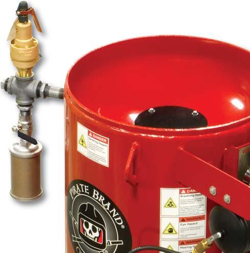
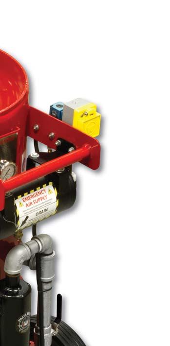
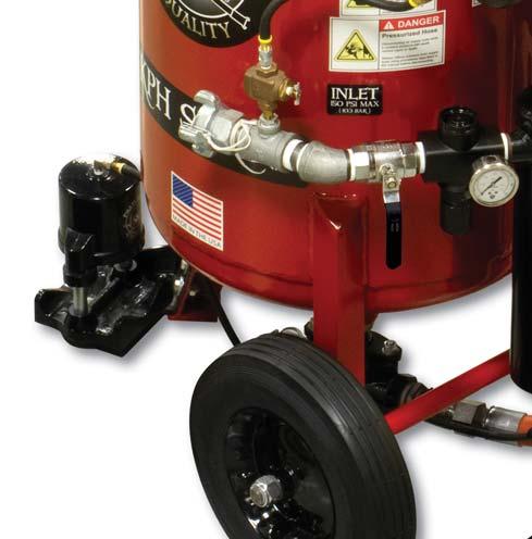
6 î How KPH Systems Work î (K-Series Pressure Hold System) WARNING: This section of the manual is designed to give you a general understanding of how the Abrasive Blaster functions. All sections of this manual must be read and understood before operating the equipment. ADDING ABRASIVE Abrasive is added through the hole in the top of the Abrasive Blaster where the Popup and its seat are located. When abrasive is added, it fl ows down through the hole, around the Pop-up and, down to the bottom of the pressure vessel where it will exit through the Metering when blasting is started. PRESSURIZATION Before pressurization can take place in a pressure hold system, the Blow-down (outlet) must be closed. Then, when a compressed air source (such as an air-compressor) is connected to the inlet of the Abrasive Blaster and turned on, the Emergency Air Tank is pressurized and the Pinch closes. The Emergency Air Tank is a safety feature that will store a reserve of compressed air that will be available to keep the pinch valve closed in the event of a compressor failure. When the Inlet is opened, compressed air can flow through the Moisture Separator and into the pressure vessel causing the Pop-up (located internally) to seal against its seat allowing the pressure vessel to become pressurized. When the control handle is activated, a control valve allows the Pinch to open allowing compressed air & abrasive to fl ow and mix. The mixture of compressed air and abrasive will now exit the Abrasive Blaster through the blast hose and nozzle connected to the coupling on the Metering and blasting begins. DEPRESSURIZATION (BLOW-DOWN) When the control handle is released in a pressure hold (KPH) system, the Pinch closes and the pressure vessel remains fi lled with compressed air. The compressed air remaining in the pressure vessel is released when the inlet valve is manually closed and the blow-down (outlet) valve is manually opened. Flow of Compressed Air Flow of Abrasive Flow of Exhaust Air During Blow-down 6
7 î How KPH Systems Work î (K-Series Pressure Hold System) Loaded Abrasive Outlet Pop-up Exhausted Air Muffler Emergency Tank Pressure Vessel Compressed Air Inlet Inlet Choke Pinch Pusher Line Air / Abrasive Mix To Blasting Nozzle Metering 7
8 î Operating Procedures î WARNING: The Procedures provided in the Operating Procedures section of the manual are designed to provide basic information on how to safely operate the features of Pirate Brand KPH Series Abrasive Blasters. Only personnel thoroughly trained in abrasive blasting should operate the Abrasive Blaster. SETTING-UP THE BLASTER INSPECT PRESSURE VESSEL When you receive your Abrasive Blaster, remove the Handway Assembly and check for foreign items that may have fallen into the Abrasive Blaster. Remove any foreign materials and reinstall the Handway Assembly. DANGER: Never perform any maintenance or attempt to open the Abrasive Blaster in any way while it is pressurized. The violent release of compressed air and propelled objects will cause serious injury or death. RE-TIGHTEN HANDWAY ASSEMBLY After the Abrasive Blaster has been pressurized for the fi rst time, tighten the nuts on the Handway Assembly. Tightening the nuts on the Handway Assembly should also be done any time after the Handway has been removed for maintenance before and after the next pressurization. DANGER: Never perform any maintenance or attempt to open the Abrasive Blaster in any way while it is pressurized. The violent release of compressed air and propelled objects will cause serious injury or death. PURGE AIR SUPPLY HOSE Before connecting the Air Supply Hose to the Abrasive Blaster, purge the hose of any moisture or foreign debris. Standing water or moisture in the air line will cause degraded performance of the Abrasive Blaster. Air supplied to the Abrasive Blaster must be clean, dry and cool. ATTACH REMOTE CONTROL HANDLES Attach the Remote Control Handle to the Blast Hose near the Nozzle with hose clamps or heavy wire ties. Form a loop of Twinline/Control Cord that comes 6 away from the Blast Hose, runs 6 parallel to the Blast Hose, and comes 6 back to the Blast Hose. Using duct tape, attach the Twinline/Control Cord to the Blast Hose where the loop ends by wrapping the tape around the Blast Hose twice and then around the Twinline/Control Cord. This creates a strain-relief attachment and is only necessary on the fi rst connection near the Control Handle. Starting from the Nozzle end of the Blast Hose, attach the Twinline/Control Cord to the blast hose by wrapping duct tape around both every 3 feet Outlet Pop-up Muffler Strainer Emergency Air Tank Nozzle Compressed Air Supply Hose Control Handle Pinch Blast Hose Pressure Vessel Inlet Moisture Separator Drain Choke Pusher Line Metering 8
9 î Operating Procedures î PRE-BLAST CHECK Before each use of the Abrasive Blaster, it must be checked to ensure it is in a safe condition to be used. Closely examine all components of the Abrasive Blaster for signs of excessive wear, worn out seals and hoses, or damaged components. If any component of the Abrasive Blaster is found to be damaged or worn, it must be replaced before blasting. WARNING: Never use an Abrasive Blaster if any components are damaged or worn. Damaged or worn parts must be replaced before use. ADDING ABRASIVE Before filling the Abrasive Blaster, make sure the inlet valve is closed and the pressure vessel is in a depressurized state. Abrasive is added by pouring it into the top of the Abrasive Blaster where the abrasive can flow around the Pop-up and into the pressure vessel. Do not overfill the Abrasive Blaster. Do not allow foreign materials to enter the Abrasive Blaster. BEFORE YOU BLAST REMOTE CONTROL SYSTEM Abrasive Blasters must use a Remote Control System (commonly known as deadman) to start and stop abrasive blasting. Remote Control Systems can be electric or pneumatic. Electric: Connect the Remote Control to the Abrasive Blaster s female twist-lock connector. Connect a 12 VDC power source (12V Battery or Optional 120 VAC to 12 VDC converter) to the Abrasive Blaster s male twist-lock connector. Pneumatic: Connect the Remote Control twinline hose to the quick disconnect fi ttings. The twinline hose is supplied with different size fi ttings on each of the 2 lines to prevent them from being connected to the Abrasive Blaster incorrectly. Do not modify or reverse these fi ttings. It is not recommended that Pneumatic Remote Control Systems are used when the Blast Hose length will be longer than 100 feet. WARNING: Never operate the Abrasive Blaster without a Remote Control System. DANGER: Never reach into the Pop-up opening while filling the Abrasive Blaster. It can close without warning causing severe injury or death WARNING: Pirate Brand Abrasive Blasters may not be used with abrasives containing silica. Never use abrasives containing silica. WARNING: Never fill the abrasive blaster with the inlet valve in the open position. Always close the inlet valve before filling. WARNING: Electrically conductive abrasives may not be used with abrasive blasters using Electric Remote Control Systems without changing to sealed strain relief connectors. WARNING: Never attempt to move or transport the Abrasive Blaster when it contains Abrasive. WARNING: Never use bleeder type Remote Control Handles such as Clemco or A-BEC style handles with Pirate-Brand KPH Series Equipment as they may cause the Abrasive Blaster to start without warning or to not stop the Abrasive Blaster when released. WARNING: Never reverse or modify pneumatic Remote Control twinline hose fi ttings. DANGER: Always use caution around electric sources to avoid electric shock. Do not operate electrical remote controlled Abrasive Blasters in wet or other hazardous environments CONNECTING HOSES Before connecting hoses to the Abrasive Blaster, make sure the Inlet is closed and the compressed air supply is shut off. Connect the hose coming from the compressed air supply to the inlet on the Abrasive Blaster and secure with safety clips. Connect the blast hose to the coupling on the Metering at the base of the Abrasive Blaster and secure with safety clips (Use mechanics/safety wire when using optional BIG-GUN full port couplings). WARNING: Always use safety devices like clips and whip-checks (safety cables) at hose connections. Optional BIG-GUN full port couplings require the use of safety/mechanics wire for proper securing. 9
10 î Operating Procedures î PRESSURIZING THE ABRASIVE BLASTER Before pressurizing the Abrasive Blaster make sure the following conditions occur: ß All BEFORE YOU BLAST procedures have been followed. ß The Inlet is closed. ß The Blow-down (Outlet ) is closed. ß The Remote Control Handle is released. ß All hose connections are secure and have a safety clip or safety/mechanics wire installed. ß The Abrasive Blaster is set up in a safe and level location where all people in the vicinity are aware of its presence. ß All necessary safety equipment is present and being worn by all people in the vicinity of the Abrasive Blaster. ß Only personnel who have been thoroughly trained and have read and understand the manual are in the vicinity of the Abrasive Blaster When these conditions are met, turn on the compressed air source. Allow the Emergency Air Tank to become fully pressurized to at least 100 PSI (6.89 BAR) before continuing. Use the supplied pressure gauge on the emergency tank to check for pressurization. Open the Inlet on the Abrasive Blaster. The Abrasive Blaster is now ready to begin blasting. DANGER: Never perform any maintenance or attempt to open the Abrasive Blaster in any way while it is pressurized. The violent release of compressed air and propelled objects will cause serious injury or death. DANGER: Never supply compressed air exceeding 150 PSI (10.3 BAR) to the Abrasive Blaster. DANGER: Never operate a KPH system if the Emergency Air Tank is not fully pressurized to at least 100 PSI. If the Emergency Air Tank is found to not be holding pressure, discontinue use of the blaster until repairs are made. WARNING: Blast Hose may kick back when Remote Control Handle is activated. Be prepared and brace yourself for kick back. Blasters with MPV Metering s or #100 Metering s will normally kick back erratically for a short time when started. BLASTING WARNING: All those who will be in the area while blasting is to occur must be properly trained, read the manual, and be wearing safety equipment to protect from the hazards described by the WARNING and DANGER labels located on the Abrasive Blaster. If any labels are worn or missing they must be replaced. USING THE ABRASIVE BLASTER After pressurizing the Abrasive Blaster, it is ready to begin blasting. Activate the Remote Control Handle to start the fl ow of abrasive and compressed air. Adjustments to the air/abrasive mixture can be made by turning the handle on MPV Series Metering s. For #100 Metering s, the fl ow of abrasive can be increased by loosening the nuts on the top of the valve, and decreased by tightening the nuts. The nuts must be tightened or loosened equally and if they are loosened too far, air will leak when pressurized. WARNING: If the adjustment bolts are set too loose on the #100 Metering, air and abrasive can escape at high velocity around the donut washer injuring nearby personnel. There will be a delay between a change made at the Metering and what comes out of the Nozzle depending on the length of Blast Hose being used. Adjustments to the Metering should only be made when Abrasive Blaster is not in operation. To stop the fl ow of compressed air and abrasive, deactivate the Remote Control Handle and blasting will stop after a short time. How long it takes for blasting to stop will depend on the length of Blast Hose being used. DANGER: Airborne particles produced by abrasive blasting can cause respiratory disease. All persons operating or located near the blasting site must wear approved NIOSH / OSHA approved breathing equipment. Never use abrasive containing silica. WARNING: Only personnel thoroughly trained in abrasive blasting should operate the Abrasive Blaster. This manual only provides basic information on how to safely operate the features of Pirate Brand KPH Series Abrasive Blasters. WARNING: Never point the blast Nozzle at yourself, other people, or the Abrasive Blaster. WARNING: The Choke must be completely open when blasting or damage to equipment will occur. 10
11 î Operating Procedures î DRAINING THE MOISTURE SEPARATOR During blasting, the Moisture Separator must be periodically drained. The best way to accomplish this is to leave the drain valve slightly open all the time so it constantly leaks air and forces moisture out. WARNING: The Abrasive Blaster must be supplied with clean, cool, dry compressed air in order to function properly. The included Moisture Separator on the abrasive blaster may not be suffi cient to achieve this depending on the quality of the air being supplied. SHUTTING DOWN THE ABRASIVE BLASTER When blasting is complete, the Abrasive Blaster will need to be shut down. Make sure the Remote Control Handles are released, then close the Inlet. Slowly open the Blow-down to allow the compressed air stored in the Abrasive Blaster to escape. BLASTING DISCONNECTING THE AIR SUPPLY HOSE After the Abrasive Blaster has been depressurized, and the Inlet has been closed, the Compressed Air Supply Hose may still contain pressure which must be released before disconnecting the hose. To do this shut off the compressed air at its source, and open the Drain and Blow-Down on the Abrasive Blaster. Slowly open the inlet valve on the Abrasive Blaster. The compressed air stored in the Compressed Air Supply Hose can now escape through the Drain. When you no longer hear air escaping through the drain valve, squeeze the Compressed Air Supply Hose to confi rm the absence of compressed air. After confi rming the absence of compressed air in the Compressed Air Supply Hose it is ready to be disconnected. The Emergency Air Tank should still be pressurized at this point and is ready for its required daily maintenance inspection (see MAINTENANCE PROCEDURES section for details). After performing the maintenance inspection, The Emergency Air Tank drain may now be opened to drain any collected moisture and depressurize the emergency air tank. DANGER: Never disconnect any compressed air supply hose without fi rst performing the DISCONNECTING AIR SUPPLY HOSE procedure described above. Failure to do so can cause the hose to blow off violently injuring or killing nearby people. Outlet Pop-up Muffler Strainer Emergency Air Tank Nozzle Compressed Air Supply Hose Control Handle Pinch Blast Hose Pressure Vessel Inlet Moisture Separator Drain Choke Pusher Line Metering 11
12 î Maintenance Procedures î Maintenance Schedule DANGER: Never perform any maintenance or attempt to open the Abrasive Blaster in any way while it is pressurized. The violent release of compressed air and propelled objects will cause serious injury or death. WARNING: Maintenance procedures are to be performed by experienced qualifi ed personnel only. Failure to perform maintenance procedures correctly at the intervals specifi ed below can lead to performance problems and equipment failure, and will void the equipment warranty. Procedure to be Performed Maintenance Interval 1 Inspect Personal Protective Equipment (PPE) Every 8 Hours Of Use Including but not limited to: Respirators, Airline Filters, Carbon-Monoxide Monitors, Hearing Protection, Eye Protection, Foot Protection, Protective Clothing & Gloves. Reference 29 CFR General Requirements (PPE) 29 CFR Eye (PPE) 29 CFR Respiratory (PPE) 29 CFR Feet (PPE) 29 CFR Protective Clothing & Gloves (PPE) 26 CFR Hearing (PPE) 2 Inspect Remote Control Handle and Control Hose/Cord Every 8 Hours Of Use 3 Inspect Blast Hose, Couplings & Gaskets Every 8 Hours Of Use 4 Inspect Blasting Nozzle Every 8 Hours Of Use 5 Inspect Air Hose, Couplings & Gaskets Every 8 Hours Of Use 6 Inspect Emergency Air Tank for Bleed Down Every 8 Hours Of Use 7 Inspect & Clean Blow-down Muffler Every 40 Hours Of Use 8 Inspect Pop-Up & Pop-Up Gasket Every 200 Hours Of Use 9 Service #400 Pinch Every 200 Hours Of Use 10 Inspect / Service Metering Every 600 Hours Of Use 11 Service Control (Electric Models) Every 600 Hours Of Use Descriptions of maintenance procedures referenced in this table are located on the next page. 12
13 î Maintenance Procedures î Procedure Details 1. Inspect Personal Protective Equipment (PPE) Inspect ALL Personal Protective Equipment (PPE) for proper fit, condition & operation as designed. Replace, repair, or be fi tted as needed. 2. Inspect Remote Control Handle and Control Hose/Cord Pneumatic Remote Control Systems: Inspect Control Handle for damage making sure the Safety Flap/Lever Lock/Button is in good working order and replace or repair as needed. Inspect twinline hoses and replace if leaks, areas that show abrasion, or soft spots are found. Electric Remote Control Systems: Inspect Control Handle for damage making sure the switch and boot are in good working order and replace as needed. Inspect control cord and replace if damaged plug ends, areas that show abrasion, exposed wires, or cracks are found. Always use the ball & chain with the chain secured around the operators wrist. Replace the ball & chain assembly if lost or damaged. 3. Inspect Blast Hose, Couplings & Gaskets Inspect Blast Hose for leaks, abrasion & soft spots, and replace as needed. Inspect couplings for damage, leaks & wear, and replace as needed. Inspect coupling gaskets for leaks & wear, and replace as needed. Always use safety clips & whip checks (safety cables) at Blast Hose connections. BIG-GUN full port couplings require the use of safety/mechanics wire for proper securing. PAY SPECIAL ATTENTION TO THE SECTION OF BLAST HOSE WHICH COMES IN CONTACT WITH THE PINCH VALVE. WHEN THIS AREA BECOMES WORN, CRACKED OR SOFT, REMOVE THE COUPLING, TRIM THE BLAST HOSE BACK PAST THE WORN AREA AND REINSTALL THE COUPLING OR REPLACE ENTIRE BLAST HOSE. 4. Inspect Blasting Nozzle Inspect the Blasting Nozzle for wear and proper bore diameter. Replace the Blasting Nozzle when the bore diameter has worn to 1/16 wider than its original diameter. Example: replace a #5 nozzle (5/16 bore) when the bore reaches 3/8 5. Inspect Air Hose, Couplings & Gaskets Inspect Air Hose for leaks, abrasion & soft spots, and replace as needed. Inspect couplings for damage, leaks & wear, and replace as needed. Inspect coupling gaskets for leaks & wear, and replace as needed. Always use safety clips & whip checks (safety cables) at Air Hose connections. 6. Inspect Emergency Air Tank For Bleed Down After depressurizing the pressure vessel and disconnecting the air supply hose as described in the OPERATING PROCEDURES Section, watch the pressure gauge on the Emergency Air Tank. If the Emergency Air Tank system is working properly, the pressure contained in the tank will not drop. If it does, discontinue use of the blast equipment until the problem is corrected. Possible causes of bleed down are: A. The #400 Pinch is leaking and need to be serviced. B. The Check on the Emergency Air Tank is damaged, defective or worn out and needs to be replaced. C. The Pull Cord Drain is damaged, defective or worn out and needs to be replaced. D. The air supply hose between the Emergency Air Tank and the #400 Pinch (or control valve on electric models is leaking. 7. Inspect & Clean Blow-down Muffler Remove the Blow-down muffl er, turn it upside-down and tap on a hard surface to free trapped debris. If muffl er is clogged and can t be cleaned out suffi ciently, it must be replaced. 8. Inspect Pop-Up & Pop-Up Gasket Inspect the Pop-Up & Pop-Up Gasket for wear and replace as necessary. 9. Service #400 Pinch Disassemble, clean & inspect the #400 Pinch for proper operation and worn components. Replace any worn components and lubricate with silicone grease before reassembling. 10. Inspect / Service Metering Disassemble, clean & inspect the Metering for proper operation and worn components. Replace any worn components found. 11. Service Control (Electric Models) Disassemble, clean & inspect for proper operation and worn components. Replace any worn components found. Lubricate with silicone grease before reassembling. 13
14 î Troubleshooting î Performance Related Issues DANGER: Never attempt to open the Abrasive Blaster in any way while it is pressurized. Use extreme caution when performing troubleshooting procedures that involve pressurizing the Abrasive Blaster. Troubleshooting procedures are to be performed by experienced qualifi ed personnel only. NO ABRASIVE FLOW WHEN BLASTING (AIR ONLY) Possible Causes: 1. The Abrasive Blaster is empty or has no Abrasive in it. 2. The Metering is closed or has not been adjusted properly. 3. There is an obstruction in the Metering. To clear the obstruction for MPV series & #100 Metering s, perform the following procedure: MPV - Turn the knob on the Metering clockwise until it stops and then turn the knob counter-clockwise 9 full turns to open it completely. #100 Metering - Depressurize the abrasive blaster. Loosen (but do not remove) the adjustment bolts equally until they start to turn easily, then tighten them both 1 full turn. Repressurize the abrasive blaster. WARNING: If the adjustment bolts are set too loose on the #100 Metering, air and abrasive can escape at high velocity around the donut washer injuring nearby personnel. Depress the control handle and have a second qualified person close the choke valve for 2 seconds, and then open it again immediately. This will push minor obstructions such as a small amount of wet abrasive, a piece of paper from a bag, or bridged paint chips through the Metering and out through the Nozzle. Readjust the Metering back to the desired setting for blasting, and check to see if the obstruction has been cleared. If there is still an obstruction you must depressurize the Abrasive Blaster, remove the pusher line, and remove the Metering to check for a steady stream of abrasive. If the remaining abrasive in the pressure vessel does not flow freely out of the pressure vessel, there is a large obstruction. If abrasive flows, wait until the Abrasive Blaster is empty before reinstalling the Metering. If you have determined there is a large obstruction, then the obstruction must be removed from inside the Pressure Vessel. To do this, make sure the Abrasive Blaster is depressurized, then remove the Handway Assembly. Scoop or vacuum out all of the abrasive from inside the pressure vessel and remove the obstruction. Reinstall the Handway Assembly and Metering, and tighten them securely, then Refill the Abrasive Blaster. 4. The Abrasive Blaster has wet abrasive in it. The wet abrasive must be removed by depressurizing the Abrasive Blaster, removing the Handway Assembly, and scooping or vacuuming it out. Dry abrasive must always be used. Clean, cool, dry air must be supplied to the Abrasive Blaster in order to prevent the abrasive from getting wet. ABRASIVE STREAM IS TOO HEAVY OR THROBBING WHEN BLASTING Possible Causes: 1. Choke is partially closed. Never run the Abrasive Blaster with the Choke in any other position except fully open or damage to the Abrasive Blaster will occur. 2. The Metering needs to be adjusted. LOW PRESSURE AT THE NOZZLE Possible Causes: 1. Air compressor is the wrong size (too small) or the load button has not been pushed or turned on. 2. Nozzle is worn out and the compressor cannot keep up with the increased demand. 3. Air supply hose to the blast machine is too small. 4. There is a hole in the blast hose. 5. Handway Assembly is leaking. 6. Choke is partially closed. Never run the Abrasive Blaster with the Choke in any other position except fully open or damage to the Abrasive Blaster will occur. 7. Abrasive Metering is open too far. 8. Obstruction in Nozzle. 9. Regulator needs adjustment (if equipped). ABRASIVE BLASTER WILL NOT TURN ON OR IS SLOW TO TURN ON Possible Causes: 1. Air compressor is the wrong size (too small) or the load button has not been pushed or turned on. 2. Nozzle is worn out and the compressor cannot keep up with the increased demand. 3. Air supply hose to the blast machine is too small. 4. Control hoses and/or fittings are leaking micron strainer clogged. 6. Obstruction in Nozzle. 7. The Pneumatic Control Handle is damaged, defective or worn out (if equipped). 8. The Electric Control Handle is damaged, defective or worn out (if equipped). 9. The Electric Control Coil is defective (if equipped). 10. Power Source (battery or AC-DC converter) is not providing sufficient power to open electric control valves (if equipped). 11. The Electric Control Cord is damaged, defective or worn out (if equipped). 12. Control stuck or in need of service due to lack of lubrication, or is damaged, defective or worn out (if equipped). SAFETY TANK WILL NOT FILL OR IS SLOW TO FILL Possible Causes: micron strainer is clogged. 14
15 î Troubleshooting î Operational Related Issues DANGER: Never attempt to open the Abrasive Blaster in any way while it is pressurized. Use extreme caution when performing troubleshooting procedures that involve pressurizing the Abrasive Blaster. Troubleshooting procedures are to be performed by experienced qualifi ed personnel only. BLAST MACHINE TURNS ON ACCIDENTALLY OR WITHOUT WARNING Possible Causes: 1. The safety flap, lever or lock button on the Control Handle is damaged or missing. 2. The Pneumatic Control Handle is damaged, defective or worn out (if equipped). 3. A bleeder type control handle has been installed. WARNING: Never use bleeder type Remote Control Handles such as Clemco or A-BEC style handles with Pirate-Brand KPH Series Blasters as they may cause the Abrasive Blaster to start without warning or to not stop the Abrasive Blaster when released. 4. The Electric Control Handle is damaged, defective or worn out (if equipped). 5. The Electric Control Cord is damaged, defective or worn out (if equipped). 6. #400 Pinch does not have the required 100 PSI minimum supplied to them from the emergency air tank (if equipped). Check the air lines to and from the emergency air tank for leaks. Check the 90 Micron Strainer for clogging and clean or replace if necessary. BLAST MACHINE IS SLOW TO TURN OFF OR WILL NOT TURN OFF WHEN CONTROL HANDLE IS RELEASED Possible Causes: 1. A bleeder type control handle has been installed. WARNING: Never use bleeder type Remote Control Handles such as Clemco or A-BEC style handles with Pirate-Brand KPH Series Blasters as they may cause the Abrasive Blaster to start without warning or to not stop the Abrasive Blaster when released. 2. The Pneumatic Control Handle is damaged, defective or worn out (if equipped). 3. The Electric Control Handle is damaged, defective or worn out (if equipped). 4. The Electric Control Cord is damaged, defective or worn out (if equipped). 5. The Control is stuck or in need of service due to lack of lubrication, or is damaged, defective or worn out. 6. #400 Pinch is stuck or in need of service due to lack of lubrication, or is damaged, defective or worn out. 7. #400 Pinch does not have the required 100 PSI minimum supplied to them from the emergency air tank. Check the air lines to and from the emergency air tank for leaks. Check the 90 Micron Strainer for clogging and clean or replace if necessary. EMERGENCY AIR TANK DOES NOT HOLD PRESSURE See MAINTENANCE PROCEDURES section for diagnosis and repair information. Outlet Pop-up Muffler Strainer Emergency Air Tank Nozzle Compressed Air Supply Hose Control Handle Pinch Blast Hose Pressure Vessel Inlet Moisture Separator Drain Choke Pusher Line Metering 15
16 î Warranty î PIRATE BRAND ABRASIVE BLAST POT EQUIPMENT 5 YEAR / 10 YEAR LIMITED WARRANTY 5 YEAR LIMITED ABRASIVE BLAST POT WARRANTY. Manufacturer warrants the complete abrasive blast pot it manufactures to be free of defects in material and workmanship for a period of fi ve (5) years from the date of invoice. 10 YEAR LIMITED PRESSURE VESSEL WARRANTY. Manufacturer warrants the abrasive blast pot pressure vessel it manufactures to be free of defects in material and workmanship for a period of ten (10) years from the date of invoice. LIMITATION OF WARRANTIES AND REMEDIES. THIS WARRANTY IS EXTENDED ONLY TO THE BUYER WHO PURCHASES THE ABRASIVE BLAST POT DIRECTLY FROM THE MANUFACTURER OR ITS AUTHORIZED DISTRIBUTORS AND IS NON-TRANSFERABLE. THE PURCHASER S EXCLUSIVE REMEDY ARISING FROM ITS PURCHASE OR USE OF THE PRODUCT SHALL BE STRICTLY LIMITED TO THE REPAIR OR REPLACEMENT OF THE PRODUCTS, AT THE DISCRETION OF THE MANUFACTURER, AND ALL WARRANTY CLAIMS OR REQUESTS MUST BE MADE IN WRITING TO THE MANUFACTURER WITHIN TEN (10) DAYS AFTER FAILURE OF THE PRODUCT. ALL OBLIGATIONS OR LIABILITIES OF MANUFACTURER OR SELLER FOR DAMAGES ARISING OUT OF OR IN CONNECTION WITH THE PRODUCT AND USE OR PERFORMANCE OF THE PRODUCTS, EXCEPT AS EXPRESSLY PROVIDED HEREIN, ARE FULLY DISCLAIMED AND EXCLUDED, AND NO SELLER OR DISTRIBUTOR HAS ANY AUTHORITY TO MAKE ANY WARRANTY OR ASSUME ANY LIABILITY ON BEHALF OF THE MANUFACTURER IN CONNECTION WITH THE SALE OF THE PRODUCT EXCEPT AS STATED HEREIN. AS A CONDITION OF THE PURCHASE, PURCHASER AGREES THAT MANUFACTURER AND SELLER SHALL NOT, UNDER ANY CIRCUMSTANCES, BE LIABLE FOR ANY COST OF FREIGHT, SHIPPING OR TRANSPORTATION, LABOR, SPECIAL CHARGES, NORMAL MAINTENANCE SERVICES, LOST OPERATING TIME, LOSS OF USE, LOST PROFITS, LOSS OF GOODWILL, CONSEQUENTIAL DAMAGES, PUNITIVE OR EXEMPLARY DAMAGES, OR OTHER DAMAGES OR LOSS. OTHER THAN AS DESCRIBED HEREIN, MANUFACTURER AND SELLER MAKE NO WARRANTY OF ANY KIND, EXPRESS OR IMPLIED, WITH RESPECT TO THE PRODUCTS, AND SPECIFICALLY DISCLAIM ANY WARRANTY OF MERCHANTABILITY, FITNESS FOR A PARTICULAR PURPOSE, OR OTHER WARRANTY. PURCHASER ASSUMES ALL RISK AND LIABILITY RESULTING FROM THE USE OF THE PRODUCTS. PURCHASER FURTHER AGREES AS A CONDITION OF THE SALE AND THE USE OF THE PRODUCT, THAT ANY DAMAGES OR RISK OF LOSS OTHER THAN AS DESCRIBED HEREIN ABOVE, SHALL BE THE EXCLUSIVE RESPONSIBILITY OF THE PURCHASER AND NOT THE MANUFACTURER OR SELLER. MANUFACTURER AND SELLER SHALL NOT BE LIABLE FOR ANY DAMAGES INCURRED BY ANY PERSON AS A RESULT OF MISUSE, IMPROPER INSTALLATION, IMPROPER APPLICATION, IMPROPER OPERATION OF THE PRODUCTS, NORMAL WEAR AND TEAR, ALTERATIONS OR MODIFICATIONS MADE TO THE PRODUCTS, OR ACCIDENT. THE USE OF REPLACEMENT PARTS NOT PROVIDED OR AUTHORIZED BY THE MANUFACTURER VOIDS ALL WARRANTIES. A COMPLETELY FILLED OUT WARRANTY CARD MUST BE RETURNED TO THE MANUFACTURER WITHIN THIRTY (30) DAYS OF PURCHASE OF THE PRODUCT OR ALL WARRANTIES ARE VOID. PRODUCT MUST BE MAINTAINED IN ACCORDANCE TO THE MAINTENANCE SCHEDULE PROVIDED IN THE PRODUCT MANUAL, FAILURE TO MAINTAIN THE PRODUCT IN ACCORDANCE WITH THE MAINTENANCE SCHEDULE VOIDS ALL WARRANTIES. THIS WARRANTY DOES NOT COVER FACTORY INSTALLED OR CUSTOMER INSTALLED ACCESSORIES. WARRANTY CLAIMS. Warranty claims must be submitted to the manufacturer within ten (10) days after failure of the product. Contact information for warranty claims: Forecast Sales, Inc Tobey Dr. Indianapolis, IN Effective July 8,
17 î Pressure Vessel Parts Lists î CU. FT. 6.5 CU. FT P VESSEL, PORTABLE, 3.5 CU. FT. (100 LITERS), 150 PSI (10.3 BAR), 110 CONE BOTTOM, 7-1/2" CLEARANCE, 18" DIA, INCLUDES: HANDWAY ASSEMBLY, POP-UP, POP-UP GASKET, SCREEN & BAG BREAKER P VESSEL, PORTABLE, 6.5 CU. FT. (185 LITERS), 150 PSI (10.3 BAR), 110* CONE BOTTOM, 7-1/2" CLEARANCE, 24" DIA, INCLUDES: HANDWAY ASSEMBLY, POP-UP, POP-UP GASKET, SCREEN & BAG BREAKER S VESSEL, STATIONARY, 3.5 CU. FT. (100 LITERS), 150 PSI (10.3 BAR), 110 CONE BOTTOM, 7-1/2" CLEARANCE, 44" OAH, 18" DIA, INCLUDES: HANDWAY ASSEMBLY, POP- UP, POP-UP GASKET, SCREEN & BAG BREAKER PLUNGER, SEALING, COATED, 6" RING, "O", 6" PB GASKET, HANDWAY, 6" x 8" PB HANDWAY CRAB ASSY 6" x 8" S VESSEL, STATIONARY, 6.5 CU. FT. (185 LITERS), 150 PSI (10.3 BAR), 110 CONE BOTTOM, 7-1/2" CLEARANCE, 51" OAH, 24" DIA, INCLUDES: HANDWAY ASSEMBLY, POP- UP, POP-UP GASKET, SCREEN & BAG BREAKER PB WHEEL & TIRE, 3.5 CU FT WHEEL & TIRE, 6.5 CU FT PB NUT, NYLOCK, 3/4" UNC PB NUT, NYLOCK, 1" UNC PB AXLE, 3/4" x 22" PB AXLE 1" x 33", PB LID, 18" DIA W/HANDLE, POWDER COATED PB LID, 24" DIA W/HANDLE, POWDER COATED M3286 BRACKET, MOUNTING FOR #400 PINCH VALVE (INCLUDES ALL MOUNTING HARDWARE) 11 PB EMERGENCY AIR TANK MOUNTING BRACKET (INCLUDES 2 BRACKETS AND ALL MOUNTING HARDWARE) 17
18 î Pipe String Parts Lists î KPH SERIES - Pneumatic Controls 18
19 î Pipe String Parts Lists î KPH SERIES - Pneumatic Controls 5 UM-100 AIR HOSE COUPLING, 2 LUG, 1" MALE NPT 5 UF-125 * See Parts Lists Section for detailed parts list. ** See Control Handle Parts Lists Section for detailed parts list. AIR HOSE COUPLING, 4 LUG, 1-1/4" FEMALE NPT 6 NOT USED PB NIPPLE, TBE, GALV, 1-1/4" x CLOSED PB TEE, GALV, 1" x 1" x 1/2" PB TEE, GALV, 1-1/4" x 1-1/4" x 1/2" PB NIPPLE, TBE, GALV, 1" x CLOSED PB NIPPLE, TBE, GALV, 1-1/4" x CLOSED PB ELBOW, STREET, 45, GALV, 1" 9 10 VB100 BALL VALVE, FULL PORT, 1" NPT 10 VB125 BALL VALVE, FULL PORT, 1-1/4" NPT PB-P MOISTURE TRAP 1" (1"M INLET x 1-1/4"M OUTLET, 150 CFM, POWDER COATED BLACK) PB-P MOISTURE TRAP 1-1/4" (1-1/4"M INLET x 1-1/4"M OUTLET, 150 CFM, POWDER COATED BLACK) PB NIPPLE, HEX 1/4"MNPT x 1/4" MNPT 13 VB025 BALL VALVE, FULL PORT, 1/4" NPT PB ELBOW, GALV, 90, 1-1/4" PB NIPPLE, TBE, GALV, 1-1/4" x 3" PB ELBOW, STREET, 90, GALV, 1-1/4" PB TEE, GALV, 1-1/4" x 1" x 1-1/4" PB TEE, GALV, 1-1/4" PB NIPPLE, TBE, SCHEDULE 80, GALV, 1-1/4" x 3" PB NIPPLE, TBE, GALV, 1" x CLOSED PB NIPPLE, TBE, GALV, 1-1/4" x 8" PUSHER LINE KIT (FLEX) 1" x 20", OAL 24" PUSHER LINE KIT (FLEX) 1-1/4" x 20", OAL 24" FITTING, 1" MNPT x 1" M-FLARE FITTING, 1-1/4" MNPT x 1-1/4" M-FLARE 22 VC100 CHECK VALVE, SWING 1" 22 VC125 CHECK VALVE, SWING 1-1/4" PB NIPPLE, TBE, SCHEDULE 80, GALV, 1" x CLOSED 23 NOT USED 24* PB MPV, 1", W/URETHANE SLEEVE 24* PB MPV, 1-1/4", W/URETHANE SLEEVE 25 SB-2-IR PB PB PB NIPPLE, TBE, SCHEDULE 80, GALV, 1" x CLOSED PB NIPPLE, TBE, SCHEDULE 80, GALV, 1-1/4" x CLOSED PB BUSHING, GALV, 1-1/2" x 1" PB BUSHING, GALV, 1-1/2" x 1-1/4" 30* 1MV-C MV-70 32* 1PV-C PB PB PB PB PB PB PB PB 41 HT PB 43 PB PB PB PB PB PB PB 51** PB PB 3.5 CU. FT. 6.5 CU. FT PB MUFFLER, BLOWDOWN, 1" MNPT 2 VB100 BALL VALVE, FULL PORT, 1" NPT PB ELBOW, STREET 90, GALV, 1" PB NIPPLE, TBE, GALV, 1" x 3" THD QUICK COUPLING, IRON, 1-1/2" NIPPLE, TBE, SCHEDULE 80, GALV, 1-1/4" x CLOSED BUSHING, GALV, 2" x 1-1/4" VALVE, #100 METERING, COMPLETE, 1-1/2" NPT INLET THRD CPLG, STD NPS, ALUMINUM, 2", (SB-5/P-32), 150 PSI MAX VALVE, #400 PINCH, COMPLETE SWIVEL 90, 1/4"MNPT x 1/4"F HOSE, PUSH-ON INSERT 1/4" x 1/4" NPT HOSE, AIR, INSTA-GRIP, BLACK, NOMINAL 1/4" ID, 300 PSI BUSHING, GALV, 1/2" x 1/4" STRAINER, BRZ 1/4" 90 MICRON STRAIGHT SWIVEL, 1/4"MNPT x 1/4"F VALVE, 1/4", BALL CHECK HEX NIPPLE 1/4" NPT x 1/4" W/BALL ST EMERGENCY AIR TANK GAUGE, PRESSURE, PSI PULL CORD DRAIN VALVE DUST ELIMINATOR, 1/4" MNPT VALVE, DIAPHRAGM CONTROL NIPPLE, HEX, 1/4" MNPT x 1/8" MNPT PLUG, 1/4" BRASS SOCKET, 1/4" BUSHING, PLATED 1/4" x 1/8"NPT HOSE, TWINLINE CONTROL, ASSEMBLY, YEL/YEL W/BLACK STRIPE, NOMINAL 3/16" ID x 55' HANDLE, CONTROL, PNEUMATIC (DEADMAN CONTROL HANDLE) HANDLE, CONTROL, PNEUMATIC #2 (DEADMAN CONTROL HANDLE) HANDLE, CONTROL, PNEUMATIC #3 (DEADMAN CONTROL HANDLE) NOT USED 19
20 î Pipe String Parts Lists î KPH SERIES - Electric Controls 20
21 î Pipe String Parts Lists î KPH SERIES - Electric Controls PB MUFFLER, BLOWDOWN, 1" MNPT 2 VB100 BALL VALVE, FULL PORT, 1" NPT PB ELBOW, STREET 90, GALV, 1" PB NIPPLE, TBE, GALV, 1" x 3" 5 UM-100 AIR HOSE COUPLING, 2 LUG, 1" MALE NPT 5 UF-125 * See Parts Lists Section for detailed parts list. AIR HOSE COUPLING, 4 LUG, 1-1/4" FEMALE NPT 6 NOT USED PB NIPPLE, TBE, GALV, 1-1/4" x CLOSED PB TEE, GALV, 1" x 1" x 1/2" PB TEE, GALV, 1-1/4" x 1-1/4" x 1/2" PB NIPPLE, TBE, GALV, 1" x CLOSED PB NIPPLE, TBE, GALV, 1-1/4" x CLOSED PB ELBOW, STREET, 45, GALV, 1" 9 10 VB100 BALL VALVE, FULL PORT, 1" NPT 10 VB125 BALL VALVE, FULL PORT, 1-1/4" NPT PB-P MOISTURE TRAP 1" (1"M INLET x 1-1/4"M OUTLET, 150 CFM, POWDER COATED BLACK) PB-P MOISTURE TRAP 1-1/4" (1-1/4"M INLET x 1-1/4"M OUTLET, 150 CFM, POWDER COATED BLACK) PB NIPPLE, HEX 1/4"MNPT x 1/4" MNPT 13 VB025 BALL VALVE, FULL PORT, 1/4" NPT PB ELBOW, GALV, 90, 1-1/4" PB NIPPLE, TBE, GALV, 1-1/4" x 3" PB ELBOW, STREET, 90, GALV, 1-1/4" PB TEE, GALV, 1-1/4" x 1" x 1-1/4" PB TEE, GALV, 1-1/4" PB NIPPLE, TBE, SCHEDULE 80, GALV, 1-1/4" x 3" PB NIPPLE, TBE, GALV, 1" x CLOSED PB NIPPLE, TBE, GALV, 1-1/4" x 8" PUSHER LINE KIT (FLEX) 1" x 20", OAL 24" PUSHER LINE KIT (FLEX) 1-1/4" x 20", OAL 24" FITTING, 1" MNPT x 1" M-FLARE FITTING, 1-1/4" MNPT x 1-1/4" M-FLARE 22 VC100 CHECK VALVE, SWING 1" 22 VC125 CHECK VALVE, SWING 1-1/4" PB NIPPLE, TBE, SCHEDULE 80, GALV, 1" x CLOSED 23 NOT USED 24* PB MPV, 1", W/URETHANE SLEEVE 24* PB MPV, 1-1/4", W/URETHANE SLEEVE 25 SB-2-IR PB PB PB 3.5 CU. FT. 6.5 CU. FT. THD QUICK COUPLING, IRON, 1-1/2" NIPPLE, TBE, SCHEDULE 80, GALV, 1-1/4" x CLOSED BUSHING, GALV, 2" x 1-1/4" NIPPLE, TBE, SCHEDULE 80, GALV, 1" x CLOSED PB NOT USED NIPPLE, TBE, SCHEDULE 80, GALV, 1-1/4" x CLOSED PB BUSHING, GALV, 1-1/2" x 1" PB BUSHING, GALV, 1-1/2" x 1-1/4" 30* 1MV-C10 VALVE, #100 METERING, COMPLETE, 1-1/2" NPT INLET 31 1MV-70 THRD CPLG, STD NPS, ALUMINUM, 2", (SB-5/P-32), 150 PSI MAX 32* 1PV-C10 VALVE, #400 PINCH, COMPLETE PB SWIVEL 90, 1/4"MNPT x 1/4"F PB HOSE, PUSH-ON INSERT 1/4" x 1/4" NPT PB HOSE, AIR, INSTA-GRIP, BLACK, NOMINAL 1/4" ID, 300 PSI PB BUSHING, GALV, 1/2" x 1/4" PB STRAINER, BRZ 1/4" 90 MICRON PB STRAIGHT SWIVEL, 1/4"MNPT x 1/4"F PB VALVE, 1/4", BALL CHECK PB HEX NIPPLE 1/4" NPT x 1/4" W/BALL ST 41 HT EMERGENCY AIR TANK PB GAUGE, PRESSURE, PSI 43 PB PULL CORD DRAIN VALVE PB DUST ELIMINATOR, 1/4" MNPT PB ELBOW, STREET, 90, GALV, 1/4" PB PIPE PLUG, GALV, 1/4" VALVE, CONTROL, 12 VDC VALVE, CONTROL, END PLATE KIT COIL, CONTROL VALVE, 12 VDC VALVE, CONTROL, REPAIR KIT K-SERIES ELECTRIC CONTROL ASSEMBLY, 12VDC W/ 2-LUG CONNECTORS WEATHERPROOF COVER WITH 2-LUG TWIST-LOCK FEMALE CONNECTOR PB EXTN CORD W/CONNECTORS, 55', 2 PRONG, 2 WIRE ELECTRIC SEALED REMOTE CONTROL SWITCH W/ BALL & CHAIN, 2 PRONG MALE CONNECTOR PB POWER CORD, 25' 12VDC, 2-LUG FEMALE TWIST-LOCK CONNECTOR, 2 PRONG MALE TWIST-LOCK CONNECTOR, 2 PRONG 21

")

 888-2263-400PB HANDLE, CONTROL, ELECTRIC ELECTRIC REMOTE CONTROL HANDLE #2 888-2263-401PB HANDLE, CONTROL, ELECTRIC #2 PB-31131 1/2\" 3 PART SEALED CONTROL CORD CONNECTOR (REQUIRED WHEN")
22 î Control Handle Parts Lists î PNEUMATIC REMOTE CONTROL HANDLE (NOT FOR USE WITH STEEL ABRASIVES) PB HANDLE, CONTROL, PNEUMATIC PB HANDLE, CONTROL, PNEUMATIC, REPAIR KIT, INCLUDES # 1, 2, 3 & PB HEX NIPPLE 1/4" NPT x 1/4" W/BALL ST PB HEX NIPPLE 1/8" NPT x 1/8" W/BALL ST COMES STANDARD WITH PNEUMATIC KPH PNEUMATIC REMOTE CONTROL HANDLE # PB HANDLE, CONTROL, PNEUMATIC # PB PB HANDLE, CONTROL, PNEUMATIC #2, REPAIR KIT, INCLUDES #1, 2 & 3 HANDLE, CONTROL, PNEUMATIC #2, SAFETY FLAP PB HEX NIPPLE 1/4" NPT x 1/4" W/BALL ST PB HEX NIPPLE 1/8" NPT x 1/8" W/BALL ST PNEUMATIC REMOTE CONTROL HANDLE #3 (NOT FOR USE WITH STEEL ABRASIVES) PB HANDLE, CONTROL, PNEUMATIC # PB HANDLE, CONTROL, PNEUMATIC #3, REPAIR KIT PB HEX NIPPLE 1/4" NPT x 1/4" W/BALL ST PB HEX NIPPLE 1/8" NPT x 1/8" W/BALL ST COMES STANDARD WITH ELECTRIC KPH ELECTRIC SEALED REMOTE CONTROL SWITCH W/ BALL & CHAIN ELECTRIC SEALED REMOTE CONTROL SWITCH W/ BALL & CHAIN, 2 PRONG MALE CONNECTOR BALL & CHAIN ONLY FOR ELECTRIC SEALED REMOTE CONTROL SWITCH PB /2" 3 PART SEALED CONTROL CORD CONNECTOR (REQUIRED WHEN USING STEEL ABRASIVES) ELECTRIC REMOTE CONTROL HANDLE (NOT FOR USE WITH STEEL ABRASIVES) PB HANDLE, CONTROL, ELECTRIC ELECTRIC REMOTE CONTROL HANDLE # PB HANDLE, CONTROL, ELECTRIC #2 PB /2" 3 PART SEALED CONTROL CORD CONNECTOR (REQUIRED WHEN USING STEEL ABRASIVES) PB HANDLE, CONTROL, ELECTRIC #2, REPAIR KIT, INCLUDES #1, 2 & PB HANDLE, CONTROL, #2, SAFETY FLAP 22

23 î Parts Lists î 23
 5 SBG-1 GASKET, STANDARD 6 1MV-90 1/2\" STUD 7 1MV-100 1/2\" NUT 8 1MV-110")
24 î Parts Lists î #100 Metering 1MV-C10 VALVE, #100 METERING, COMPLETE, 1-1/2" NPT INLET 1 1MV-40 DONUT WASHER 2 1MV-50 BASE, 1-1/2" INLET 3 1MV-60 TOP 4 1MV-70 THRD CPLG, STD NPS, ALUMINUM, 2", (SB-5/P-32) 5 SBG-1 GASKET, STANDARD 6 1MV-90 1/2" STUD 7 1MV-100 1/2" NUT 8 1MV-110 WASHER 24

25 î Parts Lists î PB PB PB PB VALVE, MANUAL PLUNGER, 1", W/URETHANE SLEEVE VALVE, MANUAL PLUNGER, 1-1/4", W/URETHANE SLEEVE VALVE, MANUAL PLUNGER, 1-1/2", W/URETHANE SLEEVE VALVE, MANUAL PLUNGER, REPAIR KIT W/URETHANE SLEEVE, INCLUDES # 2, 5, 7, 8 & PB VALVE, MANUAL PLUNGER, SEAL KIT, W/URETHANE SLEEVE, INCLUDES 7, 8 & PB VALVE, MANUAL PLUNGER, KNOB PB VALVE, MANUAL PLUNGER, ROLL PIN PB VALVE, MANUAL PLUNGER, BOLT W/WASHER PB VALVE, MANUAL PLUNGER, CAP PB VALVE, MANUAL PLUNGER, PLUNGER PB VALVE, MANUAL PLUNGER, BODY PB VALVE, PLUNGER SEAL PB VALVE, MANUAL PLUNGER, SLEEVE, URETHANE PB VALVE, MANUAL PLUNGER, GASKET PB PB PB MPV (Manual Plunger ) VALVE, MANUAL PLUNGER, PIPE NIPPLE 1" FEMALE x 1-1/2" MALE VALVE, MANUAL PLUNGER, PIPE NIPPLE 1-1/4" MALE x 1-1/2" MALE VALVE, MANUAL PLUNGER, PIPE NIPPLE 1-1/2" MALE x 1-1/2" MALE 25


26 î Blasting Set-Up î BLK-050-3AL Blast Hose Nozzles Not Included 3/4" BLAST HOSE ASSEMBLY, 50', INCLUDES NOZZLE HOLDER BLK-050-3AL BLK-050-3AL 1" BLAST HOSE ASSEMBLY, 50', INCLUDES NOZZLE HOLDER 1-1/4" BLAST HOSE ASSEMBLY, 50', INCLUDES NOZZLE HOLDER BLK-050-4AL 3/4" EXTENSION HOSE ASSEMBLY, 50' BLK-050-4AL 1" EXTENSION HOSE ASSEMBLY, 50' BLK-050-4AL 1-1/4" EXTENSION HOSE ASSEMBLY, 50' 27WT-1 27WC-1 27WC-15 27WT-2 SAFETY CABLE, 1/2" - 1" HOSE TO EQUIP. SAFETY CABLE, 1/2" - 1" HOSE TO HOSE. SAFETY CABLE, 1-1/4" HOSE TO HOSE. SAFETY CABLE, 1-1/4" - 3" HOSE TO EQUIP. 26


")

27 î Blasting Set-Up î Air Dryers RPB NOVA PB PB PB PB PB AIR DRYER ADPB PSIG OR PSIG AIR DRYER ADPB PSIG OR PSIG AIR DRYER ADBP-750/950, PSIG OR PSIG AIR DRYER ADPB PSIG OR PSIG AIR DRYER ADPB PSIG OR PSIG NOVA 2000 ASTRO Breathing Equipment NV PFC PFC PFC RPB NOVA 3 RESPIRATOR PACKAGE NOVA 2000 RESPIRATOR PACKAGE ASTRO RESPIRATOR PACKAGE COOL TUBE HOT TUBE RADEX CO MONITOR (120V) RADEX CO MONITOR (12V) RESPIRATOR PACKAGES INCLUDE RESPIRATOR HELMET, 50' BREATHING AIR SUPPLY HOSE, AND RADEX AIRLINE FILTER. 27


28 î Available Accessories î C D B A 28

 1-1/4\" REGULATOR KIT (6.")


 DUAL TIMER CONTROL BOX W/ KEY PB-9805023P-01 RESET &")
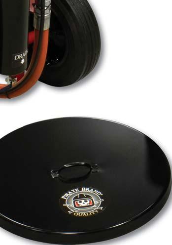
29 î Available Accessories î A PB PB Lids LIDS ARE IMPORTANT FOR KEEPING MOISTURE FROM FALLING INTO THE ABRASIVE BLASTER IN OUTDOOR APPLICATIONS. MOISTURE IN THE ABRASIVE BLASTER CAN CAUSE OBSTRUCTIONS IN THE METERING VALVE LEADING TO COSTLY DOWN-TIME. B PB-CI PB-CI LID FOR 3.5 KPH ABRASIVE BLASTERS LID FOR 6.5 KPH ABRASIVE BLASTERS Regulator Kits ADDING A REGULATOR KIT TO YOUR ABRASIVE BLASTER WILL ALLOW YOU TO BLAST AT LOWER PRESSURES TO ACHIEVE CUSTOM FINISHES OR HELP CONTROL PROFILE 1" REGULATOR KIT (3.5 CU FT KPH) 1-1/4" REGULATOR KIT (6.5 CU FT KPH) D PB PB UMBRELLA FOR STATIONARY BLASTERS WHERE ABRASIVE IS BEING FED FROM AN OVERHEAD SYSTEM THE UMBRELLA WILL KEEP EXCESS WEIGHT OFF OF THE POP-UP ALLOWING IT TO FUNCTION PROPERLY. REQUIRES REMOVAL OF THE BUILT-IN BAG BREAKER AND SCREEN " POP UP VALVE UMBRELLA SCREENS FOR BLASTERS EQUIPPED WITH AN ABRASIVE UMBRELLA, USE THESE SCREENS TO KEEP DEBRIS FROM ENTERING THE PRESSURE VESSEL. ONLY USED WITH KPH SERIES BLASTERS WHERE THE BAG BREAKER HAS BEEN REMOVED TO ACCOMIDATE AN ABRASIVE UMBRELLA. SCREEN FOR 3.5 KPH ABRASIVE BLASTERS SCREEN FOR 6.5 KPH ABRASIVE BLASTERS C Relief Kit ADDING THIS ASME RELIEF VALVE KIT TO YOUR BLASTER CAN PREVENT DANGEROUS OVERPRESSURIZATION. LOCAL CODES MAY REQUIRE A DIFFERENT VALVE Job Timer KEEP TRACK OF TIME SPENT ON A JOB AND TOTAL HOURS ON YOUR ABRASIVE BLASTER. KNOW YOUR COST, CONTROL YOUR COST & SET UP A PREVENTATIVE MAINTENANCE PROGRAM FOR YOUR BLAST EQUIPMENT PB SMALL BLASTER RELIEF VALVE KIT BIG-GUN BLAST HOSE & NOZZLES High Performance Blasting (FOR KPH WITH PNEUMATIC CONTROLS ONLY) DUAL TIMER CONTROL BOX W/ KEY PB P-01 RESET & MOUNTING BRACKET Power Supply ADD A POWER SUPPLY TO RUN ANY 12VDC ELECTRIC BLASTER ON COMMON 120AC OUTLET POWER. POWERS UP TO 4 CONTROL VALVES AT ONE TIME. PB-SMP3WP-K POWER SUPPLY 120AC 2.5 AMP OUTPUT - 2 LUG FOR KPH BIG-GUN HOSES BLK-050-3XAL BLK-050-4XAL 1-1/4" BLAST HOSE ASSEMBLY, BIG GUN FULL FLOW, W/ COUPLINGS (INCLUDES): (50') BLACK BLAST HOSE, (1) ALUMINUM FULL PORT QUICK COUPLER & (1) ALUMINUM NOZZLE HOLDER 1-1/4" BLAST HOSE EXTENSION ASSEMBLY, BIG GUN FULL FLOW W/ COUPLINGS (INCLUDES): (50') BLACK BLAST HOSE & (2) ALUMINUM FULL PORT QUICK COUPLERS BIG-GUN NOZZLES PB PB PB PB PB #5 BIG GUN TUNGSTEN CARBIDE NOZZLE #6 BIG GUN TUNGSTEN CARBIDE NOZZLE #7 BIG GUN TUNGSTEN CARBIDE NOZZLE #8 BIG GUN TUNGSTEN CARBIDE NOZZLE #10 BIG GUN TUNGSTEN CARBIDE NOZZLE FULL PORT COUPLINGS ARE REQUIRED TO CONNECT BIG-GUN BLAST HOSE TO YOUR KPH BLASTER SB-4X-AL SB-3X-A; COUPLINGS 2" ALUMINUM FULL PORT QUICK COUPLING (USE WITH #100 METERING VALVE) 1-1/2" ALUMINUM FULL PORT QUICK COUPLING (USE WITH MPV METERING VALVE) 29
3-IN-1 ABRASIVE BLAST MACHINE OWNER S MANUAL
 Abrasive blasting can create dust that may contain toxic materials from abrasive material and the surface being blasted. NEVER use abrasives containing high amounts of crystalline silica including silica
User s Manual. Read Manual SODA STO SODA STORM SERIES BLASTERS. Manual P/N: PB-MAS004
 User s Manual SODA STORM SERIES BLASTERS Featurin g The SODA STO RM SODA BL ASTING These products and equipment are not under any circumstances to be used with sand or silica products of any type and use
MBM - Series Owner s Manual
 MBM - Series Owner s Manual. Cu. Ft,. Cu. Ft,. Cu. Ft, & 0 Cu. Ft Blast Machines SUPERIOR PERFORMANCE And Quality In Blast Cleaning Equipment! WARNING Read Manual Failure to read, understand & follow all
C-Series. Pirate Brand. Product Line Brochure 3.0 / 6.0 CU FT - ABRASIVE BLASTERS. Proudly Distributed By: Rev. May 16
 Pirate Brand C-Series 3.0 / 6.0 CU FT - ABRASIVE BLASTERS Proudly Distributed By: See limited warranty documentation for complete details. Product Line Brochure Rev. May 16 (Pressure Release) ADDING ABRASIVE
C-Series. Pirate Brand. Product Line Brochure 0.5 / 1.0 CU FT - ABRASIVE BLASTERS. Proudly Distributed By: Rev. May 16
 Pirate Brand C-Series 0.5 / 1.0 CU FT - ABRASIVE BLASTERS Proudly Distributed By: See limited warranty documentation for complete details. Product Line Brochure Rev. May 16 Professional Grade Components
170-CG Feed Unit SPONGE-JET USER MANUAL. Sponge-Jet, Inc. (USA) 14 Patterson Lane Newington, NH
 14 Patterson Lane Newington, NH") SPONGE-JET 170-CG Feed Unit USER MANUAL Sponge-Jet, Inc. (USA) 14 Patterson Lane +1-603-610-7950 Newington, NH 03801 www.spongejet.com AUGUST 2014, Sponge-Jet 170-CG User Manual - REV A / DOC: M-MKTG-002ENG
SPONGE-JET 170-CG Feed Unit USER MANUAL Sponge-Jet, Inc. (USA) 14 Patterson Lane +1-603-610-7950 Newington, NH 03801 www.spongejet.com AUGUST 2014, Sponge-Jet 170-CG User Manual - REV A / DOC: M-MKTG-002ENG
ATD LB PRESSURE BLASTER INSTRUCTION MANUAL
 ATD-8402 90LB PRESSURE BLASTER INSTRUCTION MANUAL SAVE THESE INSTRUCTIONS SAFETY INSTRUCTIONS FOR SANDBLASTER 1. Before opening the tank release the air pressure on the sand tank. To do this, turn off
170-SJ Feed UnitTM 470-SJ Feed UnitTM
 SPONGE-JET 170-SJ Feed UnitTM 470-SJ Feed UnitTM USER MANUAL Sponge-Jet, Inc. (USA) 14 Patterson Lane +1-603-610-7950 Newington, NH 03801 www.spongejet.com Sponge-Jet 170-SJ / 470-SJ User Manual - REV
RASP RX3 Feed UnitTM SPONGE-JET USER MANUAL. Sponge-Jet, Inc. (USA) 14 Patterson Lane Newington, NH
 14 Patterson Lane Newington, NH") SPONGE-JET RASP RX3 Feed UnitTM USER MANUAL Sponge-Jet, Inc. (USA) 14 Patterson Lane +1-603-610-7950 Newington, NH 03801 www.spongejet.com Sponge-Jet RASP RX3 User Manual - REV A / DOC: MKT-014-ENG SPONGE-JET
SPONGE-JET RASP RX3 Feed UnitTM USER MANUAL Sponge-Jet, Inc. (USA) 14 Patterson Lane +1-603-610-7950 Newington, NH 03801 www.spongejet.com Sponge-Jet RASP RX3 User Manual - REV A / DOC: MKT-014-ENG SPONGE-JET
accidents which arise due to non-observance of these instructions and the safety information herein. SPECIFICATIONS
 18 GAUGE 2 INCH BRAD NAILER Model: 7555 CALIFORNIA PROPOSITION 65 WARNING: You can create dust when you cut, sand, drill or grind materials such as wood, paint, metal, concrete, cement, or other masonry.
accidents which arise due to non-observance of these instructions and the safety information herein. SPECIFICATIONS
 18 GAUGE 1-1/4 INCH BRAD NAILER Model: 7611 CALIFORNIA PROPOSITION 65 WARNING: You can create dust when you cut, sand, drill or grind materials such as wood, paint, metal, concrete, cement, or other masonry.
3.0 / 6.0 Cu Ft Abrasive Blasters C-Series
 / Abrasive Blasters C-Series See limited warranty documentation for complete details Features & Benefits Pirate Brand CPR abrasive blast machines include a host of features to make blasting simple, straightforward
SPECIFICATIONS Type: Twin stack, single phase Tank: 4 gallon Air Output: PSI; PSI Max PSI: 125 PSI HP: 1.
 2 GALLON TWIN STACK AIR COMPRESSOR Model: 9526 DO NOT RETURN TO STORE. Please CALL 800-348-5004 for parts and service. CALIFORNIA PROPOSITION 65 WARNING: You can create dust when you cut, sand, drill or
PRODUCT OPERATING MANUAL
 PRODUCT OPERATING MANUAL PANBLAST TM AIRSTOP II NPT PNEUMATIC CONTROL HANDLE Manual Number: ZVP PC 0108 00 SECTION 1. GENERAL INFORMATION 2. INTRODUCTION 3. INSTALLATION 4. OPERATING INSTRUCTIONS 5. MAINTENANCE
NB/NBR NITROGEN BOOSTER FOR AVIATION SERVICE
 NB/NBR NITROGEN BOOSTER FOR AVIATION SERVICE INSTALLATION, OPERATION & MAINTENANCE MANUAL INTERFACE DEVICES, INC. 230 Depot Road, Milford, CT 06460 Ph: (203) 878-4648, Fx: (203) 882-0885, E-mail: info@interfacedevices.com
ATD LBS. PRESSURE BLASTER INSTRUCTION MANUAL
 ATD-8401 40 LBS. PRESSURE BLASTER INSTRUCTION MANUAL ATD abrasive blasting equipment is designed for cleaning and removing rust, scale, paint and dirt. It is the ideal method for stripping, polishing and
User Instruction Manual
 User Instruction Manual 4500 psi Air Compressor Ver 2, 1.18 Contents Parts Included...3 Assembly Instructions...3-5 Operation Instructions...6-7 Oil Change Intervals...8 Air Filter Replacement...9 Setting
Hodge Clemco Ltd. SG-300 Suction Gun. Owner s Manual. Hodge Clemco Ltd
 Page 1 of 10 Hodge Clemco Ltd SG-300 Suction Gun Date of issue: 24/08/92 TS.OM64A Owner s Manual Hodge Clemco Ltd Orgreave Drive Sheffield S13 9NR Tel: 0114 254 8811 Email sales@hodgeclemco.co.uk www.hodgeclemco.co.uk
MINI M SERIES ABRASIVE BLASTER Cu.ft. OPERATION AND MAINTENANCE MANUAL DECEMBER 2009
 MINI M SERIES ABRASIVE BLASTER 0.9-1.8 Cu.ft. OPERATION AND MAINTENANCE MANUAL DECEMBER 2009 SAVE THIS MANUAL AND MAKE AVAILABLE TO ALL USERS OF THIS EQUIPMENT! Manual Part Number 7200-295 Rev 9-26-18
OWNER S MANUAL SUCTION GUN SG-300
 OWNER S MANUAL SUCTION GUN SG-00 Clemco International GmbH Carl-Zeiss-Straße Tel.: +49 (0) 806 90080 805 Bruckmühl Mail: info@clemco.de Germany Web: www.clemco-international.com Revision: 0.05 SG-00 SUCTION
AC1810 / AC1810-A TECHNICAL SPECIFICATIONS. Operating Pressure psi ( kgs/cm²) [AC1810] Displacement. Net Weight
![AC1810 / AC1810-A TECHNICAL SPECIFICATIONS. Operating Pressure psi ( kgs/cm²) [AC1810] Displacement. Net Weight](/thumbs/83/88369739.jpg "AC1810 / AC1810-A TECHNICAL SPECIFICATIONS. Operating Pressure psi ( kgs/cm²) [AC1810] Displacement. Net Weight") Technical Specifications Operating Instructions Maintenance Information Troubleshooting Guide Parts Diagrams AC1810 / AC1810-A THE EVOLUTION OF PERFECTION CAUTION: Before attempting to use or service this
Technical Specifications Operating Instructions Maintenance Information Troubleshooting Guide Parts Diagrams AC1810 / AC1810-A THE EVOLUTION OF PERFECTION CAUTION: Before attempting to use or service this
ATD LBS. PRESSURE BLASTER INSTRUCTION MANUAL
 ATD-8402 90 LBS. PRESSURE BLASTER INSTRUCTION MANUAL C f Pr p 65 WARNING h h er h g. ATD abrasive blasting equipment is designed for cleaning and removing rust, scale, paint and dirt. It is the ideal method
2 GALLON TWIN STACK AIR COMPRESSOR W/ HOSE REEL
 2 GALLON TWIN STACK AIR COMPRESSOR W/ HOSE REEL Model: 52024 CALIFORNIA PROPOSITION 65 WARNING: You can create dust when you cut, sand, drill or grind materials such as wood, paint, metal, concrete, cement,
AIR COMPRESSOR. Failure to follow all instructions as listed below may result in electrical shock, fire, and/or serious personal injury.
 2 GALLON AIR COMPRESSOR Model: 7517 DO NOT RETURN TO STORE. Please CALL 800-348-5004 for parts and service. CALIFORNIA PROPOSITION 65 WARNING: You can create dust when you cut, sand, drill or grind materials
Abrasive Blasters c.f. (MV3) OPERATION AND MAINTENANCE MANUAL FEBRUARY 2017
 OPERATION AND MAINTENANCE MANUAL FEBRUARY 2017") Abrasive Blasters 1.5-20 c.f. (MV3) OPERATION AND MAINTENANCE MANUAL FEBRUARY 2017 SAVE THIS MANUAL AND MAKE AVAILABLE TO ALL USERS OF THIS EQUIPMENT! Manual Part Number 7200-200MV (Scan QR tag below for
Abrasive Blasters 1.5-20 c.f. (MV3) OPERATION AND MAINTENANCE MANUAL FEBRUARY 2017 SAVE THIS MANUAL AND MAKE AVAILABLE TO ALL USERS OF THIS EQUIPMENT! Manual Part Number 7200-200MV (Scan QR tag below for
3 GALLON, OILLESS PANCAKE COMPRESSOR INSTRUCTIONS. Item #31289
 3 GALLON, OILLESS PANCAKE COMPRESSOR INSTRUCTIONS Item #31289 The EASTWOOD 3 GALLON, OILLESS PANCAKE COMPRESSOR, with an Integral Air Regulator, efficiently supplies all compressed air requirements for
Abrasive Blasters cu. ft OPERATION AND MAINTENANCE MANUAL SEPTEMBER 2008
 Abrasive Blasters 1.5-20 cu. ft OPERATION AND MAINTENANCE MANUAL SEPTEMBER 2008 SAVE THIS MANUAL AND MAKE AVAILABLE TO ALL USERS OF THIS EQUIPMENT! Manual Part Number 7200-200 AXXIOM Manufacturing, Inc.
OWNER S MANUAL. Dual Chamber Blast Machine. for 1 to 4 operators. with pneumatic. metering- and air valves
 OWNER S MANUAL Dual Chamber Blast Machine for 1 to 4 operators with pneumatic metering- and air valves Clemco International GmbH Carl-Zeiss-Straße 21 Tel.: +49 (0) 8062 90080 83052 Bruckmühl Mail: info@clemco.de
BS Series Basket Strainer
 BS Series Basket Strainer Operating, Installation, & Maintenance Manual Corrosion Resistant Fluid and Air Handling Systems. Dated 04-26-12 PRESSURE DROP SIMTECH strainers are engineered to offer the lowest
M SERIES ABRASIVE BLASTER OPERATION AND MAINTENANCE MANUAL JULY 2007
 M SERIES ABRASIVE BLASTER OPERATION AND MAINTENANCE MANUAL JULY 2007 SAVE THIS MANUAL AND MAKE AVAILABLE TO ALL USERS OF THIS EQUIPMENT! Manual Part Number 7200-285 rev 11-15 Copyright 2015 AXXIOM Manufacturing,
Model ASSEMBLY and OPERATING INSTRUCTIONS
 QUICK CHANGE AIR BRUSH KIT Model 93506 ASSEMBLY and OPERATING INSTRUCTIONS Due to continuing improvements, actual product may differ slightly from the product described herein. 3491 Mission Oaks Blvd.,
2 GAL AIR COMPRESSOR OPERATOR S MANUAL 1/3HP/2-GALLON IMPORTANT: READ THIS OPERATOR S MANUAL BEFORE USING
 ITEM# AT01101 SKU# 207-1525 OPERATOR S MANUAL 1/3HP/2-GALLON 2 GAL AIR COMPRESSOR IMPORTANT: READ THIS OPERATOR S MANUAL BEFORE USING Toll Free Helpline: 1-888-899-0146 Versions 01 TABLE OF CONTENTS SAFETY
INSTRUCTION MANUAL MST AFTERCOOLER SYSTEM MODEL
 INSTRUCTION MANUAL MST AFTERCOOLER SYSTEM MODEL 8059601 To be used with MST Model 8050501 Ambient Air Pump 7/12/05 2 TABLE OF CONTENTS GENERAL INFORMATION... 3 WARNING...4,5 UNPACKING AND AFTERCOOLER ASSEMBLY
!!!! SERVICE MANUAL PRESSURE POT 2 GALLON. Service Manual: LT Washington St 931 Progress Ave., #7
 EXEL North America, Inc. EXEL Industrial Canada, Inc. 1310 Washington St 931 Progress Ave., #7 West Chicago, IL 60185 Scarborough ONT, M1G 3V5 Ph : (800) 573 5554 Ph : (800) 450 0655 Fx : (800) 664 1511
MANUAL BE SERIES Test Benches
 The CustomCrimp Manual BE Series Test Benches are designed with features that make proof and burst testing of hydraulic hose assemblies a quick and easy procedure. CUSTOMIZED AND SPECIAL DESIGN BENCHES
Double Chamber Abrasive Blaster OPERATION AND MAINTENANCE MANUAL MAY 2013
 Double Chamber Abrasive Blaster OPERATION AND MAINTENANCE MANUAL MAY 2013 SAVE THIS MANUAL AND MAKE AVAILABLE TO ALL USERS OF THIS EQUIPMENT! Manual Part Number 7200-235 (available for downloading from
FLANGED TWO-PIECE BALL VALVES
 INTRODUCTION This instruction manual includes installation, operation, and maintenance information for FNW flanged split-body ball valves. This manual addresses lever operated ball valves only. Please
WARNING! Crystalline silica from bricks, cement and other masonry products
 1 WARNING! DO not use a Pressure Blaster until you have read this manual and you understand its contents and warnings. These warnings are included for the health and safety of the operator and those in
J Air and Water Kit Instructions Part# 02584
 J Air and Water Kit Instructions Part# 02584 Unpacking Please open and inspect your package upon receipt. Your package was packed with great care and all the necessary packing materials to arrive to you
User Operation Manual and Safety Instructions
 PCP Airgun Charging Station 74 cu.ft. / 98 cu. ft. Carbon Fiber Tank & Accessories User Operation Manual and Safety Instructions BRAND: Air Venturi DESCRIPTION: PCP Airgun Charging System FILL PRESSURE:
D Series Air and Water Kit Part# 02550
 D Series Air and Water Kit Part# 02550 Unpacking Please open and inspect your package upon receipt. Your package was packed with great care and all the necessary packing materials to arrive to you undamaged.
INTRODUCTION... 3 II II II II II II II II II II II II II I 4-5 ASSEMBLY... 6,7,8 II II II II II II II... 9
 Instruction Manual rode~ AIRLINE F I LTER INTRODUCTION... 3 WARNINGS I 4-5 ASSEMBLY... 6,7,8 OPERATION I... 9 MAINTENANCE I Ill 1 0,11 PARTS LIST I 12 RPB 62/2 a rode~ A I R L I N E F I L T E R..: INTRODUCTION
FLANGED TWO-PIECE BALL VALVES
 INTRODUCTION This instruction manual includes installation, operation, and maintenance information for FNW flanged split-body ball valves. This manual addresses lever operated ball valves only. Please
5 Gallon Pressure Pot with HVLP Spray Gun and Hose
 California Air Tools 5 Gallon Pressure Pot with HVLP Spray Gun and Hose Model No. 365 Technical Data Type of feed.pressure Maximum pressure in the tank... 0,413Mpa (60PSI) Working pressure in the tank.0,
LUBRICATOR ASSEMBLY AND OPERATING INSTRUCTIONS
 AIR FILTER, REGULATOR AND LUBRICATOR 4035 ASSEMBLY AND OPERATING INSTRUCTIONS 349 Mission Oaks Blvd., Camarillo, CA 930 Visit our Web site at http://www.harborfreight.com Copyright 004 by Harbor Freight
BRS2 BLAST AND RECOVERY SYSTEM OPERATION AND MAINTENANCE MANUAL MAY 2010
 BRS2 BLAST AND RECOVERY SYSTEM OPERATION AND MAINTENANCE MANUAL MAY 2010 SAVE THIS MANUAL AND MAKE AVAILABLE TO ALL USERS OF THIS EQUIPMENT! Manual Part Number 7200-8083-285-11 AXXIOM Manufacturing, Inc.
2.5 & 5.0 GALLON PRESSURE TANKS
 2.5 & 5.0 GALLON PRESSURE TANKS Includes: MODEL 7025 MODEL 7026 MODEL 7027 MODEL 7028 2.5 Gallon Single Regulation (NON A.S.M.E.) 2.5 Gallon Dual Regulation (NON A.S.M.E.) 5.0 Gallon Single Regulation
Model PSI Compressor with 3-Gallon Air Tank 12VDC
 Model 6350 150 PSI Compressor with 3-Gallon Air Tank 12VDC IMPORTANT: It is essential that you and any other operator of this product read and understandd the contents of this manual before installing
SSFU SUPER SPRAYFAST UNIVERSAL ADHESIVE APPLICATOR
 S S F U SSFU SUPER SPRAYFAST UNIVERSAL ADHESIVE APPLICATOR MACHINERY DIVISION OWNER S MANUAL UNIT INSTRUCTIONS Please follow all SSFU Safety Instructions. Contact your Duro Dyne Tech Service if you have
450P- RV AUTOMATIC PORTABLE COMPRESSOR EXTREME SERIES
 450P- RV AUTOMATIC PORTABLE COMPRESSOR EXTREME SERIES PART NO. 45053 IMPORTANT: It is essential that you and any other operator of this product read and understand the contents of this manual before installing
RARS5000 AIR BODY SAW OWNER S OPERATING MANUAL
 RARS5000 AIR BODY SAW OWNER S OPERATING MANUAL DESCRIPTION 1. No mar 2. No mar tip 3. Housing grip 4. Trigger 5. Air inlet 6. Air inlet plug 7. Plastic board Important! It is essential that you read the
Manual. FRESH AERO OneOP Model PC (Portable Compressors) Tire Inflator. Where Imagination Meets Innovation
 Tire Inflator. Where Imagination Meets Innovation") FRESH AERO OneOP Model PC (Portable Compressors) Tire Inflator For inflating aircraft tires and all types of other vehicle tires and air operated devices Manual The Fresh Aero Group Where Imagination Meets
FRESH AERO OneOP Model PC (Portable Compressors) Tire Inflator For inflating aircraft tires and all types of other vehicle tires and air operated devices Manual The Fresh Aero Group Where Imagination Meets
3.0 Cubic Foot C-Series Blast Pot
 Operator's Manual Part # 09007 Revision: June 2, 2009.0 Cubic Foot C-Series Blast Pot with KwikFire 2 Remote Control System For more information call: 800-BLAST-IT Phone: (800) 22-7848 Fax: (6) 24-628
Installation Instructions Air Compressor Part # 2780, 2781
 Note: It is essential that the operator of this product read and understand the contents of this manual before installing and using this product. Parts Included Qty Parts Included Qty Compressor 1 Coil
Binks SG-2 Plus TM Rotary 2 QT. PRESSURE CUP
 Binks SG-2 Plus TM Rotary 2 QT. PRESSURE CUP Model No. 80-651 Rotary Agitator INTRODUCTION Binks SG-2 TM Plus Rotary 2 Qt. Pressure Cup is ideal for component spraying and industrial applications where
AIR INLINE METAL SHEAR
 AIR INLINE METAL SHEAR ASSEMBLY and OPERATING INSTRUCTIONS 3491 Mission Oaks Blvd. / Camarillo, CA 93011 Copyright 1997 by Harbor Freight Tools. All rights reserved. No portion of this manual or any artwork
Yoke Block Instruction Manual
 Yoke Block Instruction Manual ! WARNING IMPORTANT: READ MANUAL COMPLETELY BEFORE OPERATING THIS DEVICE This manual contains instructions on periodically required checks to be performed by the user. These
SERVICE MANUAL MODEL BA600AMST-S1 BREATHING AIR PANEL
 SERVICE MANUAL MODEL BA600AMST-S1 BREATHING AIR PANEL WARNING: Do not attempt to operate this equipment without first reading and understanding the service manual enclosed with this device. 2/05 GENERAL
RCV-125 REMOTE CONTROL SYSTEM IMPORTANT WARNING FOR SAFER BLAST CLEANING
 OWNER S MANUAL RCV-125 REMOTE CONTROL SYSTEM IMPORTANT WARNING FOR SAFER BLAST CLEANING 1. Use protective equipment: Abrasive-resistant clothing, safety shoes, leather gloves, ear protection, CE-approved
ULTRA HIGH PRESSURE PAINT GRATE CLEANER FCT-JS OPERATION AND MAINTENANCE MANUAL
 ULTRA HIGH PRESSURE PAINT GRATE CLEANER FCT-JS OPERATION AND MAINTENANCE MANUAL 466 S. Skylane Drive DURANGO, COLORADO 81303 970-259-2869 PHONE 970-259-2868 FAX www.stoneagetools.com sales@stoneagetools
3/8" Dr. Air Butterfly Impact Wrench
 8192106 3/8" Dr. Air Butterfly Impact Wrench Owner s Manual Read and understand all instructions before use. Retain this manual for future reference. Specifications Construction: Polished aluminum and
450P AUTOMATIC PORTABLE COMPRESSOR EXTREME SERIES
 EXTREME SERIES PART NO. 45043 IMPORTANT: It is essential that you and any other operator of this product read and understand the contents of this manual before installing and using this product. SAVE THIS
4-in-1 Professional Inflator Kit
 4-in-1 Professional Inflator Kit Owner s Manual WARNING: Read carefully and understand all ASSEMBLY AND OPERATION INSTRUCTIONS before operating. Failure to follow the safety rules and other basic safety
FOR INSTALLING CO 2 BLENDER KIT (P/N IN BEER SYSTEM
 IMI CORNELIUS INC One Cornelius Place Anoka, MN 55303-623 Telephone (800) 238-3600 Facsimile (612) 22-326 INSTALLATION INSTRUCTIONS FOR INSTALLING CO 2 BLENDER KIT (P/N 111612000 IN BEER SYSTEM SECONDARY
ABRASIVE SYSTEM ABRASIVE REGULATOR II 800# BULK ABRASIVE DELIVERY POT Abrasive Regulator II and 800# Pot Manual
 ABRASIVE SYSTEM ABRASIVE REGULATOR II 800# BULK ABRASIVE DELIVERY POT TABLE OF CONTENTS Contact Information and Customer & Technical Service... 1 1 Introduction... 1 2 Abrasive Regulator... 1 Description:...
PRODUCT OPERATING MANUAL
 PRODUCT OPERATING MANUAL PANBLAST TM VISIFLO RESPIRATOR AIRLINE FILTERS Manual Number: ZVP PC 0084 01 Pressure Equipment Directive 97/23/EC SECTION 1. GENERAL INFORMATION 2. INTRODUCTION 3. PREPARATION
SIX R (P ) AND SEVEN R (P ) POSITION CYLINDERS Service Information
 AND SEVEN R (P ) POSITION CYLINDERS Service Information") SIX R431006322 (P -063892-00001) AND SEVEN R431006321 (P -063981--00002) POSITION CYLINDERS Service Information The six and seven position cylinders are medium duty pneumatic positioning devices that operate
SIX R431006322 (P -063892-00001) AND SEVEN R431006321 (P -063981--00002) POSITION CYLINDERS Service Information The six and seven position cylinders are medium duty pneumatic positioning devices that operate
INTENDED USE TECHNICAL SPECIFICATIONS
 1/2IN. HEAVY-DUTY AIR IMPACT WRENCH OWNER S MANUAL WARNING: Read carefully and understand all INSTRUCTIONS before operating. Failure to follow the safety rules and other basic safety precautions may result
1/2 Twin Hammer Composite. Air Impact Wrench ASSEMBLY AND OPERATING INSTRUCTIONS
 1/2 Twin Hammer Composite Air Impact Wrench 95098 ASSEMBLY AND OPERATING INSTRUCTIONS Due to continuing improvements, actual product may differ slightly from the product described herein. 3491 Mission
Hydraulic Punch Drivers
 SERVICE MANUAL 7804SB / 7806SB Quick Draw 7704SB / 7706SB Quick Draw Flex Quick Draw Hydraulic Punch Drivers Serial Codes AHJ and YZ Read and understand all of the instructions and safety information in
OPERATOR S MANUAL 1.5 HP/6-GALLON 6 GAL AIR COMPRESSOR IMPORTANT: READ OPERATOR S MANUAL BEFORE USING. Toll Free Helpline:
 ITEM# 0306 SKU# 07-55 OPERATOR S MANUAL.5 HP/6-GALLON 6 GAL AIR COMPRESSOR IMPORTANT: READ OPERATOR S MANUAL BEFORE USING Toll Free Helpline: -888-899-06 VY03A36669 TABLE OF CONTENTS Specifications------------------------------------------------------------------------------------------------
HPB25 Hydraulic Paving Breaker
 INSTRUCTION MANUAL HPB25 Hydraulic Paving Breaker Read and understand all of the instructions and safety information in this manual before operating or servicing this tool. Register this product at www.greenlee.com
BLAST CABINET FOOT PEDAL & GUN INSTRUCTIONS. Item #21133
 BLAST CABINET FOOT PEDAL & GUN INSTRUCTIONS Item #21133 The EASTWOOD BLAST CABINET FOOT PEDAL KIT is designed to replace the standard trigger operated blast gun in the Eastwood Blast Cabinets. The Foot
Model No Product Name Handpiece Only Complete System
 Ney QC 700 E 30,000 RPM IECE 30,000 R N HANDPIE IVEN HA R DRIV AIR D Owner & Operator's Manual Model No Product Name 7201326 Handpiece Only 7201325 Complete System Description Page Safety... 2 Setup...
BLAST N' VAC PACKAGE BNVP-300/BNVP-600 OPERATING INSTRUCTIONS
 BLAST N' VAC PACKAGE BNVP-300/BNVP-600 OPERATING INSTRUCTIONS INVENTIVE MACHINE CORPORATION, PO BOX 7585, AKRON, OH 44306 (330) 785-2500 (800)325-1074 FAX (330) 785-2510 TABLE OF CONTENTS 1. 0 GENERAL...
Technical Operating Instructions for Magnum Cutting Systems. for online instructions
 Technical Operating Instructions for Magnum Cutting Systems http://www.magnumusa.com/operating-video.html for online instructions In Case of Emergency Immediately Call for Medical Aid. Familiarize yourself
JARVIS. Model CPE Hock and Neck Cutter EQUIPMENT... TABLE OF
 74 Hock and Neck Cutter EQUIPMENT SELECTION... Ordering No. TABLE OF CONTENTS... Page with Control Circuit. 4304003 only... 4304004 Balancer... 1350084 Control Circuit... 3350010 Air Hose (Yellow)... 3323003
SUPERIOR PERFORMANCE
 LAB-1 ABR BLASTROOM & PNEUMATIC RECOVERY SYSTEM OPERATION & MAINTENANCE MANUAL BLAST ROOM SUPERIOR PERFORMANCE And Quality In Blast Cleaning Equipment! WARNING Read Manual Failure to read, understand &
LUDLUM MODEL 239-1F FLOOR MONITOR. Revised December 2010
 LUDLUM MODEL 239-1F FLOOR MONITOR Revised LUDLUM MEASUREMENTS, INC. 501 OAK ST., P.O. BOX 810 SWEETWATER, TX 79556 325/235-5494 FAX: 325/235-4672 STATEMENT OF WARRANTY Ludlum Measurements, Inc. warrants
Operating Manual. Model BAC-30RT30/BAC-30DC
 Model BAC-30RT30/BAC-30DC Manual No. BAC012 (Rev 1 October 2002) Operating Manual AIR SYSTEMS INTERNATIONAL, INC. 829 Juniper Crescent, Chesapeake, Va., 23320 Telephone (757) 424-3967 Toll Free 1-800-866-8100
SERVICE MANUAL MODEL BA050BMST BREATHING AIR PANEL
 www.modsafe.com SERVICE MANUAL MODEL BA050BMST BREATHING AIR PANEL WARNING: Do not attempt to operate this equipment without first reading and understanding the service manual enclosed with this device.
Installation Operating Instructions for Simple Duplex Manual Manifolds PX-TSD Series
 Introduction Powerex manifolds are cleaned, tested and prepared for the indicated gas service and are built in accordance with the Compressed Gas Association guidelines. The manifold consists of a regulator
VRS Assembly & Operating Instructions
 VRS Assembly & Operating Instructions Models VRS-18 Pn #270003 VRS-24 Pn #270006 VRS-30 Pn #270010 Not for use on pressure vessels equipped with Automatic exhaust valve (680 controls) EMPIRE ABRASIVE EQUIPMENT
MODEL 840 AIR HYDRAULIC PUMP INSTRUCTION
 MODEL 840 AIR HYDRAULIC PUMP INSTRUCTION Jackco Transnational Inc. 202 South El Monte, CA 888-452-2526 www.jackco.com FOR YOUR SAFETY Read all instructions, warnings and cautions carefully. Follow all
1 DRIVE INDUSTRIAL IMPACT WRENCH
 1 DRIVE INDUSTRIAL IMPACT WRENCH 92622 ASSEMBLY AND OPERATING INSTRUCTIONS 3491 Mission Oaks Blvd., Camarillo, CA 93011 Visit our Web site at http://www.harborfreight.com Copyright 2004 by Harbor Freight
1. CONDITIONS FOR USE 2. SAFETY
 1. CONDITIONS FOR USE This micro abrasive blaster may only be operated: Indoors; Below 6500 ft above sea level altitude; Ambient air temperature between 40-105 F (5-40 C); Maximum relative humidity of
G7S Hand Pump Owner s Manual
 G7S Hand Pump Owner s Manual Copyright Air Venturi 2018 Version 4-18 Specifications 24.80 inches long closed 43.31 inches long extended 4500 psi/310 bar max pressure Features Integral manometer (pressure
SERVICE MANUAL MODEL BA100BMST 100 SCFM PORTABLE AIR PANEL
 Product Manual MST Portable Air Filtration System SERVICE MANUAL MODEL BA100BMST 100 SCFM PORTABLE AIR PANEL WARNING: Do not attempt to operate this equipment without first reading and understanding the
Halsey Taylor Owners Manual 4410 Freeze Resistant Tubular Fountain STOP!
 Halsey Taylor Owners Manual 4410 Freeze Resistant Tubular Fountain STOP! PLEASE READ THE FOLLOWING INFORMATION. ITALLATION ITRUCTIO FOR THE 4410FR FTN. WITH 97243C SINGLE VALVE CONTROL ASSEMBLY ARE LOCATED
2-Liter Pressure Cup. Instructions - Parts List C
 Instructions - Parts List 2-Liter Pressure Cup 309925C Model 234413 50 psi (345 kpa, 3.4 bar) Maximum Fluid Pressure 160 psi (1.1 MPa, 11 bar) Maximum Air Inlet Pressure This manual contains important
GETZ EQUIPMENT INNOVATORS RECOVERY SYSTEM CLEAN AGENT FE-36 / HALOTRON 1 PART NO. 4G59751 OPERATIONS MANUAL
 GETZ EQUIPMENT INNOVATORS CLEAN AGENT FE-36 / HALOTRON 1 PART NO. 4G59751 OPERATIONS MANUAL GETZ EQUIPMENT INNOVATORS PEKIN, ILLINOIS, U.S.A. PHONE: (888) 747-4389 FAX: (309) 495-0625 Limited Warranty
PORTABLE AFTERCOOLER MODEL CA-700 PORTABLE AFTERCOOLER/FILTER AFTERCOOLER OPERATION MANUAL ORIGINAL INSTRUCTIONS
 PORTABLE AFTERCOOLER MODEL CA-700 PORTABLE AFTERCOOLER/FILTER AFTERCOOLER OPERATION MANUAL ORIGINAL INSTRUCTIONS Aftercooler Operation Manual.0 INTRODUCTION Suitable for most blasting applications, the
Pressure Relief Valve Instruction Manual
 CVR3-M0_062017 Pressure Relief Valve Instruction Manual MODEL: CVR3 SFA Companies 10939 N. Pomona Ave. Kansas City, MO 64153 Tel: 888-332-6419 * Fax: 816-448-2142 E-mail: sales@bvahydraulics.com Website:
Model B-1 Pipe Line Strainer 3, 4, 6 & 8 Inch (DN80, DN100, DN150 & DN200) 175 psi (12,1 bar) General Description. Technical Data
 175 psi (12,1 bar) General Description. Technical Data") Technical Services: Tel: (800) 381-312 / Fax: (800) 71-5500 Customer Service/Sales: Tel: (215) 362-0700 / (800) 523-6512 Fax: (215) 362-5385 Model B-1 Pipe Line Strainer 3,, 6 & 8 Inch (DN80, DN100, DN150
Technical Services: Tel: (800) 381-312 / Fax: (800) 71-5500 Customer Service/Sales: Tel: (215) 362-0700 / (800) 523-6512 Fax: (215) 362-5385 Model B-1 Pipe Line Strainer 3,, 6 & 8 Inch (DN80, DN100, DN150
IMPORTANT SAFETY INSTRUCTIONS
 IMPORTANT SAFETY INSTRUCTIONS CAUTION - To reduce risk of electrical shock: - Do not disassemble. Do not attempt repairs or modifications. Refer to qualified service agencies for all service and repairs.
OPERATING and MAINTENANCE INSTRUCTIONS MAXIS 3K Puller (M3K-M)
") OPERATING and MAINTENANCE INSTRUCTIONS MAXIS 3K Puller (M3K-M) 04/17 (M3K-M) READ AND UNDERSTAND ALL OF THE INSTRUCTIONS AND SAFETY INFORMATION IN THIS MANUAL BEFORE OPERATING OR SERVICING THIS TOOL TABLE
OPERATING and MAINTENANCE INSTRUCTIONS MAXIS 3K Puller (M3K-M) 04/17 (M3K-M) READ AND UNDERSTAND ALL OF THE INSTRUCTIONS AND SAFETY INFORMATION IN THIS MANUAL BEFORE OPERATING OR SERVICING THIS TOOL TABLE
APCO ARV CLEAN WATER AIR RELEASE VALVES. Model 50A
 APCO ARV CLEAN WATER AIR RELEASE VALVES Model 50A Instruction D12013 February 2017 Instructions These instructions provide installation, operation and maintenance information for APCO ARV Clean Water Air
Owner s Manual A VMAC Eliminator After-Cooler
 Owner s Manual A800185 VMAC Eliminator After-Cooler 1 www.vmacair.com Contents VMAC Document Revisions..1 Equipment Specifications and Accessories... 2 Safety... 3 Installation... 5 Calibration/Testing...
Installation, Operation & Maintenance Manual for Flo-Max Coupler Bracket Model FM150
 Installation, Operation & Maintenance Manual for Flo-Max Coupler Bracket Model FM150 January 2013 Form FVC 084 - Rev 02 IMPORTANT: KEEP THIS DOCUMENT WITH THE PRODUCT UNTIL IT REACHES THE END USER. 1.
100C Air Compressor Kit
 10010 100C Air Compressor (standard mounting bracket, CE Spec) 10014 100C Air Compressor (no leader hose or check valve, CE Spec) 10016 100C Air Compressor (with Omega Bracket, CE Spec) IMPORTANT: It is