Instruction Manual for
|
|
|
- Albert Gardner
- 5 years ago
- Views:
Transcription
1 Instruction Manual for AirQuest SMT Mobile Breathing Air System Model# AQ10F-D Serial# Start-up Date: EAGLE COMPRESSORS, INC. EAGLEAIR Eagle Compressors, Inc 3003 THURSTON AVENUE - GREENSBORO, NC TEL: (336) / FAX: (336)
2 TABLE OF CONTENTS Section 1 Becoming Familiar with the AirQuest SMT Mobile Breathing Air Trailer Section 2 Operating Instructions Section 3 Air Monitor System Section 4 EAGLEAIR Purification System Section 5 Maintenance and Service Section 6 Breathing Air Compressor Pump Section 7 Material Data and Safety Sheets Section 8 Schematics and Diagrams
3 WARRANTY The Company warrants to the original purchaser that the equipment manufactured by it and delivered hereunder will be free of defects in material and workmanship. Manufactured products are warranted for twelve (12) months from the date of shipment. Compressor blocks that are supplied as an integral part of a Compressor/Purifier or Cylinder Refill System, are warranted for an additional (1) year parts only from the date of shipment. Parts are warranted for six (6) months from the date of shipment. Should any failure to conform to this Warranty be reported to the Company within said period, the Company shall, upon Purchaser promptly notifying the Company in writing thereof, correct such nonconformity, by suitable repair to such equipment or, at its option, by furnishing a replacement part F.O.B. point of destination, provided the Purchaser has installed, maintained and operated such equipment in accordance with good industry practices and has complied with specific recommendations of the Company. Accessories, components, or equipment furnished by the Company, but manufactured by others, shall carry whatever warranty the manufacturers have conveyed to the Company and which can be passed on to the Purchaser. The effects of corrosion, erosion, normal wear and tear, and maintenance items such as lubricants and filters are specifically excluded from the Company s Warranty. The Company shall not be liable for any repairs, replacements, or adjustments to the equipment or any cost of labor performed by the Purchaser without the Company s prior written approval. THE COMPANY MAKES NO OTHER WARRANTY OR REPRESENTATION OF ANY KIND WHATSOEVER, EXPRESSED OR IMPLIED, EXCEPT THAT OF TITLE AND ALL IMPLIED WARRANTIES OF MERCHANTABILITY AND FITNESS FOR A PARTICULAR PURPOSE ARE HEREBY DISCLAIMED. Correction by the Company of nonconformities whether patent or latent, in the manner and for the period of time provided above, shall constitute fulfillment of all liabilities of the Company for such nonconformitites, whether based on contract, warranty, negligence, indemnity, strict liability or otherwise with respect to or arising out of such equipment. The Purchaser shall not operate equipment which is considered to be defective, without first notifying the Company in writing of its intention to do so. Any such use of equipment will be at the Purchaser s sole risk and liability. Limitation of Liability The remedies of the Purchaser set forth herein are exclusive, and the total liability of the Company with respect to this contract or the equipment and services furnished hereunder, in connection with the performance or breach thereof or from the manufacture, sale, delivery, installation, repair or technical direction covered by or furnished under this contract, whether based on contract, warranty, negligence, indemnity, strict liability or otherwise shall not exceed the purchase price of the unit of equipment upon which such liability is based. The Company and its suppliers shall in no event be liable to the Purchaser, any successors in interest or any beneficiary or assignee of this contract for any consequential, incidental, indirect, special or punitive damages arising out of this contract or any breach thereof, or any defect in, or failure of, or malfunction of the equipment hereunder, whether based upon, but not limited to, loss of use, lost profits or revenue, interest, lost goodwill, work stoppage, impairment of other goods, loss by reason of shutdowns or non-operation, increased expenses of operation, cost of purchase of replacement power or claims of Purchaser or customers of Purchaser for service interruption whether or not such loss or damage is based on contract, warranty, negligence, indemnity, strict liability or otherwise Thurston Avenue Greensboro, NC Phone (336) Fax (336)

4
5 Section 1 Becoming Familiar with the AirQuest SMT Mobile Breathing Air Trailer
6 AirQuest SMT Features The AirQuest SMT trailer is a fully self-contained mobile breathing air system, designed for towing behind an emergency vehicle. There are many features available with the AirQuest trailer. These features are listed below. 1. The trailer is equipped with an on board diesel engine for running the compressors pump. 2. Located at the rear of the trailer is a control panel, for convenient operation, of not only the trailer itself, but for the compressor, storage cylinders, and fill station. 3. Located underneath the trailer are four DOT cylinders used for storing air. These cylinders can be removed for hydrostatic testing. See the section in this manual for instructions, on how this can be done. 4. There are diagnostic lights and gauges, on the control panel and at the electric box. These will tell the operator the condition of the compressor at a glance. See the section in this manual on the compressor operation, for detailed explanations of these components. 5. Also located at the rear of the trailer is a two position SafeStation. This SafeStation is designed to contain any fragments, which may result, in the rare event that a cylinder ruptures. See the section in this manual on the operation of the SafeStation. 6. This trailer contains an Air Monitor System, which tells the operator, at a glance, how many parts per million of H2O and CO are present in the air being sent to the SCBA/SCUBA cylinders. 7. A purification system is included with the trailer that is capable of processing 165,000 cf of air. See the purification section of the manual for more detail. 8. There is also a light bar located above the control panel. This allows good visibility to the operator when running the trailer. 9. Interior lights for the trailer are provided for visibility during maintenance. A three-position switch controls these lights. In the off position, the battery is disabled and will not allow the compressor to run. The switch must be in the Auxiliary position or Lights position to run the compressor. The interior lights will come on in the lights position. Eagle Compressors, Inc. Page 1 Phone: (336) Fax: (336)

7 AirQuest SMT Operator Interface This section is designed to familiarize the operator with the location of the components necessary to efficiently operate the AirQuest trailer. 1. The tow vehicle should have a 2 5/16 ball for towing of the trailer. The AirQuest is equipped with the necessary chains and breakaway kit for safely towing the trailer. TOWING CONNECTIONS STABILIZING WHEEL 2. The trailer is equipped with interior lights for any maintenance in the interior of the trailer. Open the middle door and simply turn the switch to the LIGHTS position any time they are needed. INTERIOR LIGHT SWITCH Eagle Compressors, Inc. Page 1 Phone: (336) Fax: (336)
8 3. The rear control panel is also equipped with lights for illumination of the rear panel. This is a push button switch at the top of the control panel. LIGHT SWITCH 4. The trailer must be stabilized during operation. Lower the stabilizing stand using the tool located in the front compartment of the tongue. REAR STABILIZING STAND Eagle Compressors, Inc. Page 1 Phone: (336) Fax: (336)

9 5. Apply the emergency brake. Press down on the handle to do this. Make sure that the brake is released before transporting the trailer again. EMERGENCY BRAKE 6. There are several daily maintenance checks of fluids that should be performed. The following pictures will show the location of these points. COMPRESSOR OIL LEVEL CHECK COMPRESSOR OIL DRAIN ENGINE RADIATOR FLUID Eagle Compressors, Inc. Page 1 Phone: (336) Fax: (336)


10 7. The drive belts will need to be checked for tightness and tightened on occasion. The following pictures show the location of the bolts for performing this maintenance procedure. When adjusting the belts, loosen the four bolts on the diesel engine and then turn the adjustment screw. This will allow the diesel engine to slide. LOOSEN FOUR BOLTS AT BASE 2 ON EACH SIDE BELT ADJUSTMENT SCREW Eagle Compressors, Inc. Page 1 Phone: (336) Fax: (336)


11 8. Condensate should be drained from the system on a daily basis. The following picture shows the location of the condensate drain valve, located beneath the trailer. Treat this fluid as used engine oil and dispose of responsibly. CONDENSATE DRAIN VALVE. LOCATED UNDERNEATH TRAILER 9. The compressor pump will need to have the oil changed as shown in the maintenance chart. Connect a hose to the barb fitting and drain into a container. Dispose of the used oil responsibly. CONNECT A HOSE TO THE BARB FITTING FOR DRAINING OF OIL Eagle Compressors, Inc. Page 1 Phone: (336) Fax: (336)


12 10. The trailer is equipped with a set of diagnostic lights at the rear control panel and the interior electric box. The interior electric box also shows the temperature of the fourth stage head and the hours of operation on the compressor. The rear panel also has gauges and soft seat valves for monitoring the air pressures in the system and controlling the flow of air within the system. These devices will give the operator instant visibility and control of the running condition at all times. 11. The trailer also has diagnostic lights located on the electric box inside the trailer. This electric box also contains the temperature gauge for measuring the final stage temperature of the compressor block, and an hour meter that shows run time for the compressor. Eagle Compressors, Inc. Page 1 Phone: (336) Fax: (336)


13 12. A bleed valve is located inside the purification door. This valve is to be used to slowly bleed air out of the purification chambers when changing cartridges. Recommended bleed rate is 100 psi/ min. there is a gauge to verify this bleed rate. Also inside the purification door is an isolation valve that is used to isolate the purifier. PRESSURE GAUGE ISOLATION VALVE PURIFICATION CHAMBERS 13. Inside the trailer is a panel with the interstage pressure gauges for measuring each stage of the compressor pumps operating pressures. Eagle Compressors, Inc. Page 1 Phone: (336) Fax: (336)
 674-3621 Fax: (336) 674-7672")
14 EMERGENCY STOP LIGHT SWITCH DIAGNOSTIC LIGHTS AIR MONITOR SYSTEM STORAGE CONTROLS REGULATED PRESSURE CIRCUIT SCBA FILL CIRCUIT COMPRESSOR GAUGE STORAGE BYPASS TWO POSITION CONTAINMENT FILL STATION DIESEL ENGINE START/CONTROL PANEL Eagle Compressors, Inc. Page 1 Phone: (336) Fax: (336)

15 ELECTRIC BOX DIAGNOSTIC LIGHTS INTERIOR LIGHT SWITCH EMERGENCY STOP HOUR METER TEMPERATURE GAUGE Eagle Compressors, Inc. Page 1 Phone: (336) Fax: (336)
16
17
18
19
20 FILL SYSTEM CHECK LIST! DAILY/PRE-START UP CHECKS: 1. Check compressor oil level and add as needed with manufacturers recommended type of oil. 2. Drain condensation from muffler reservoir. 3. Observe purifier gauge ensuring pressure is maintained. If not, leak should be located and repaired. 4. Observe storage gauge, note drop in pressure from previous day. If pressure has dropped 1000 psi overnight this constitutes an excessive leak or leaks and should be addressed as soon as possible. 5. Start compressor and top off storage receivers. 6. Systems equipped with a diagnostic light bar; turn master switch to the START position, testing for defective bulbs. Replace as necessary. 7. Check SCBA fill adapter O-rings for the need to replace. 8. Check oil level, fuel, and coolant levels in the Diesel Engine. Add as needed.! NORMAL OPERATION: 1. Complete daily checks. 2. Observe interstage & final stage pressure gauges making sure system automatically drains every 15 minutes and at maximum pressure. 3. Observe interstage pressure gauges. Consult owners manual for maximum and relief pressures for each stage. NOTE: Some variances in pressure may be indicated on the gauge. 4. Observe compressor s final stage gauge, ensuring that compressor does not exceed manufacturer s recommended maximum pressure. 5. Observe the hour meter and service the purifier according to the service chart provided in the purification section of this manual.! WEEKLY CHECKS: 1. Complete daily checks. 2. Systems used less than 1 hour per week: Purge storage tanks enough to permit compressor to run for a minimum of 1 hour.! MONTHLY CHECKS: 1. Water Cooled Systems; Ensure anti-freeze protection level is adequate for your area. 2. Calibrate CO Monitor. Consult owners manual for calibration procedures.! 90 DAY INTERVAL: 1. Take air quality analysis to ensure a minimum of Grade D is met for fireman respiration equipment. 2. Grade E must be maintained for SCUBA respiratory equipment. 3. In Canada: Check as per CSA Standards.! SEMI-ANNUAL OR DETERMINED BY THE PURIFICATION MONITORING DEVICES: 1. Change purification cartridges. 2. See Purification System section of the manual. Eagle Compressors, Inc. Diesel fill sys chk list.doc Page 1 Phone: (336) Fax: (336)
21 Section 2 Operating Instructions
22 SELECTING A PROPER LOCATION FOR OPERATING THE AIRQUEST TRAILER It is very important that the AirQuest Trailer is placed in the proper environment when selecting a site to operate the compressor. Temperature is such a crucial consideration for high pressure breathing air compressors. The compressor is equipped with an internal cooling fan designed to flow across the pump for proper cooling. The ambient temperature for operating the compressor is as follows: Optimum Temperature Range is 40 F to 85 F Maximum Temperature Range 23 F to 100 F Another important consideration in the selection of a site for the compressor is the amount of contaminants in the air that can be introduced into the pump for compression. The compressor is equipped with an air intake filter installed on top of the roof. There must be a continuous supply of fresh air into the compressor. Take a look around the site, when possible to check for sources of contaminated air. Do not place the air intake near a busy street or where vehicles will be emitting Carbon Monoxide. Check the local industry to see if there are any emissions that may get into the air stream used by the compressor. It is recommended that the storage system is filled when the fresh air supply can be controlled. Use the air from storage in emergency situations.
23 PRELIMINARY START-UP PROCEDURE The trailer must be in a stable condition before operation can begin. The following steps must be completed prior to running. 1. Level the trailer with the front jack. 2. Use wheel chocks to prevent the trailer from rolling. 3. Lower the stabilizer in the back using the crank that is located under the front plate of the tongue. Refer to the diagram on the next page for location. 4. Verify that there is diesel fuel in the tank, and oil in the crankcase. 5. Access the purifier chambers and install the cartridges. Access to the purifier compartment is right side rear compartment if facing the back of the trailer. 6. Open all four doors on either side of the trailer, and the rear door. 7. Make sure the Emergency Stop Button is pulled out. The OFF-AUXILIARY- INTERIOR LIGHTS switch, located in the middle compartment, left side, if facing the rear of the trailer, has to be in the AUXILIARY or INTERIOR LIGHTS position to run the compressor. 8. Go to the back of the trailer and turn the diesel engine switch to the first position. Wait until the coil light of the display turns off. Turn the key to start the engine. 9. The POWER ON light and the PURGE CYCLE light will come on. 10. Follow the instructions for operation of the compressor and for the fill station. CAUTION: ONLY QUALIFIED PERSONNEL SHOULD OPERATE THIS EQUIPMENT. NEVER LOOSEN OR TIGHTEN ANY FITTINGS WHILE UNDER PRESSURE. MAKE SURE ALL AIR PRESSURE IS BLED OFF OF THE SYSTEM BEFORE PERFORMING ANY SERVICE. FAILURE TO DO SO MAY RESULT IN SEVERE INJURY OR DEATH. Eagle Compressors, Inc. Page 1 Phone: (336) Fax: (336)
24 PURIFICATION COMPARTMENT LOCATION DOOR LOCATION IS RIGHT SIDE REAR FACING THE BACK OF THE TRAILER PURIFICATION ISOLATION VALVE PURIFICATION CHAMBERS REAR CONTROL PANEL Storage Bank TO Valves Storage Bank FROM Valves Hose Reel Fill Valve Hose Reel Bleed Valve Eagle Compressors, Inc. Page 1 Phone: (336) Fax: (336)
25 ELECTRO / MECHANICAL COMPRESSOR START UP & OPERATION PROCEDURE 1. This procedure is only to be followed, after the section in this manual called PRELIMINARY START UP PROCEDURE, or when using shore power to run the compressor. If using shore power you must refer to the section in this manual called USING SHORE POWER 2. To start the compressor, Press the Master Start switch to ON this will illuminate the power on light and the compressor will start to build pressure after 20 seconds and continue until it reaches the preset cut-off pressure. And the final pressure light will come on. 3. OFF: When the Master Start switch is pressed to Off the compressor will unload and run a 2-minute purge cycle, stop and the power on light will turn off. 4. Make sure the Auto Condensation Drain functions properly. The Purge Cycle light will illuminate on compressor start up and approximately every 15 minutes for 20 seconds. When final pressure has been reached the compressor will unload and purge for approximately 2 minutes. This is vital to the proper operation of the compressor & purifier. Press the Purge Cycle (optional) button to manually check Auto Condensation Drain function. NOTE! Air pressure will be delivered when Purifier pressure exceeds the Priority Valve setting. 5. The compressor will automatically start when the pressure has dropped enough to reach the preset cut-in point of the pressure switch. (Roughly 500-psi differential between auto stop & start.) 6. When the Emergency Stop / Reset Switch is pressed, the compressor will shutdown immediately and unload the condensation traps and Mechanical Separator. The Emergency Stop is also a reset for a fault condition. 7. Door Ajar light will illuminate and shut down the compressor when the side service door is closed. To reset, open doors, push in and pull out the Emergency Stop button. 8. After a Power Loss to the compressor, verify the compressor rotation. The compressor rotation must be counter clock-wise (air flow across the compressor block) to lubricate and cool properly. 9. Check compressor oil daily. The compressor may be equipped with an optional Oil Level / pressure Switch. A proper oil level must be maintained or the oil level switch will shut the compressor down. And the Low Oil shut down light will illuminate. Eagle Compressors, Inc. Electro mech startup proc genset.doc 1 of 2 Phone (336) Fax: (336)
26 10. The High Temp. switch is preset to shut the compressor down if a high temp. condition occurs and illuminate the High Temp shut down light. This will prevent the compressor from exceeding manufacturer temperature specifications. 11. The Motor Overload (MOL) protection device below the Magnetic Starter provides protection to the motor if an overload condition occurs. If such a condition occurs, the motor overload will trip out and shut the compressor down and illuminate the fault shut light. The (MOL) reset button must be pressed and the compressor Master Switch must be turned OFF then push in the Emergency Stop and pull back out to reset. Turn Master switch to on to continue operation. The cooling fan also has an overload protection device that resets in the same manner. 12. The off Switch is equipped with a 2 minute Purge-Cycle. When maximum pressure has been met (designated by the pressure switch) the compressor will unload the condensate traps and mechanical separator by use of the Auto drain system and permit the compressor to run unloaded for 2 minutes then stop. Optional Moisture Monitor The moisture monitor prevents the purification system from producing unsafe air due to an increased level of moisture content, by initializing the high moisture indication lamp before chemical cartridge life has fully expired. When High Moisture is indicated at 25 ppm, the compressor will run up to 5 min, and then shut down. At this point, service of the purifier is recommended before continuing operations. Optional High CO Shutdown The CO monitor prevents the purification system from producing unsafe air due to an increased level of carbon monoxide content by shutting down the compressor when the chemical cartridge life has fully expired. The monitor is set from the factory to warn of a CO level of 10 ppm, which is the limit for Grade D and E. Standard. Note: Once the monitor has gone into an alarm condition, it takes roughly 60 seconds before actual shutdown will occur. NOTICE! When the compressor shuts down due to a compressor fault, to restart; press the Master Switch to OFF and push in the Emergency Stop to reset the lock-out relay, correct the problem, then pull out the Emergency Stop and turn the Master Switch back to ON. Eagle Compressors, Inc. Electro mech startup proc genset.doc 2 of 2 Phone (336) Fax: (336)
27
28 EAGLE COMPRESSORS Compressed Breathing Air Systems Mobile SafeStation SCBA/SCUBA CONTAINMENT FILL STATION Operating Instructions INITIAL SETTINGS FOR CONTROL 1. Regulator (On Air Control Panel)...0 PSI 2. SCBA Fill Valve (On Air Control Panel)...CLOSED 3. Fill Hose Isolation Valve on fill whips...closed 4. Bleed Valve on fill whips...open 5. Hose Reel Valve (On Air Control Panel)...CLOSED TO LOAD BOTTLES INTO MOBILE SAFESTATION 1. Start the compressor. This will allow air to flow and provide proper operation of the door. 2. Click down on the door handle. Let the door lower itself and come to a stop. 3. Pull outward on the door. Once the door starts to open, it will continue to open on its own and come to a dampened stop when fully open. 4. Note the pressure reading on the Pilot Operatihg Air gauge in the interior of the SafeStation. This reading should be approximately 100 PSI +/- 20 PSI. 5. The SCBA/SCUBA cylinders can now be loaded. 6. Attach the CGA fitting, located on the fill whip inside the containment area of the SafeStation, to the bottles. 7. Open the isolation valves on the fill whips. The isolation valves should remain open from this point on, unless the operator is using the SafeStation to fill only one bottle. Then the isolation valve must be closed on the unused whip. 8. Close the bleed valves on the fill whips. 9. Open the valves on the bottles. 10. Click up on the door handle and push up on the door. The door will automatically come to an upright position and then raise itself to its final ready position. NOTE: The Fill Stations are designed to hold 88 Cu. Ft. SCBA bottles and 80 Cu. Ft. SCUBA bottles. If smaller bottles are being used place an appropriate size block (made of wood, PVC pipe, etc.) under bottle so as not to kink the fill whips. NOTE: The SafeStation needs air at the HIGH PRESSURE INLET for proper operation of the door and the filling of bottles. However, there is a Manual Over Ride capability built in to allow the door to open or close. Cascade Operating Instructions.doc Phone (336) August 28, 2002 Fax (336) Page 1
29 EAGLE COMPRESSORS Compressed Breathing Air Systems TO FILL SCBA/SCUBA CYLINDERS NOTE: Check hydrostatic data and working pressure of the SCBA you wish to fill. If SCBA is out of certification it should not be filled. 1. Note Supply Gauge pressure is higher than bottle to be filled. If not, start compressor to recharge storage or to fill bottle directly from compressor/purifier. NOTE: The door handle must be in the up position to fill the bottles. If the door handle is clicked down during the fill process, filling of the bottles will stop. 2. Turn Regulator Knob clockwise and set Regulator Gauge to desired fill pressure. 3. Open SCBA fill valve on the air control panel slowly to start the fill process. 4. When the Regulator Gauge reaches the desired fill pressure, the bottle is full. 5. Close the SCBA Fill Valve on the panel. 6. Click down on the door handle of the SafeStation. The door will automatically lower itself. 7. Pull out on the door. Once the door starts to open it will continue on its own and come to a dampened stop when fully open. 8. Close the valves on bottles being filled. 9. Bleed the fill hose using the Bleed valves located on the fill whips. 10. Disconnect fill hose from the bottles. WARNING: Supply pressure (as shown on the Supply Pressure Gauge) must be higher than the desired fill pressure or regulated pressure. Example: An operator can ruin a Regulator by continuing to turn the knob trying to get 2216 PSIG when he only has 1000 PSIG being applied to the Regulator. WARNING: Never remove an SCBA charging adapter from the SCBA bottle with the BLEED VALVE on the fill whip closed. This valve must be open to insure there is no air remaining in the line to the bottle. TO FILL STORAGE CYLINDERS 1. Start compressor and let compressor build to final pressure as stated in the startup procedure. 2. Open To Storage Bank Valves. 3. When Storage Bank Gauge indicates full, close To Storage Bank Valves. 4. Repeat procedure for each bank of storage. Cascade Operating Instructions.doc Phone (336) August 28, 2002 Fax (336) Page 2
30 EAGLE COMPRESSORS Compressed Breathing Air Systems TO FILL SCBA/SCUBA USING COMPRESSOR ONLY 1. Start compressor and let compressor build to final pressure as stated in the startup procedure. 2. Be sure control panel valves are at initial settings. 3. Connect fill hose to SCBA/SCUBA cylinder being filled. 4. Open valve on SCBA/SCUBA cylinder being filled. 5. Open Storage Bypass Valve. 6. Observe Supply Gauge pressure exceeds SCBA/SCUBA pressure being filled. 7. Turn Regulator knob clockwise and set Regulator Gauge to desired fill pressure. 8. Open SCBA Fill Valve slowly to start the fill process. 9. When the SCBA Fill Gauge reaches the desired fill pressure, the SCBA is full. 10. Close SCBA fill valve on the panel. 11. Close the valve on the SCBA bottle you have filled. 12. Bleed Fill Hose using Bleed Valve. 13. Disconnect fill hose from SCBA. 14. The same procedure is used for the Aux fill. Just make sure the SCBA Fill Valve is closed and use the Aux Fill Valve. WARNING: Never remove an SCBA charging adapter from its mount or from the SCBA bottle with pressure indicating on the SCBA gauge. This gauge must read (0) before the charging adapter can be removed safely. TO FILL SCBA/SCUBA USING COMPRESSOR ONLY 1. Be sure control panel valves are at initial settings. 2. Connect fill hose to bottle to be filled. 3. Open valve on SCBA/SCUBA cylinder being filled. 4. Open the From Storage Bank #1 Valve. Be sure storage pressure is higher than pressure rating of the SCBA you wish to fill. 5. Turn Regulator Knob clockwise and set Regulator Gauge to desired fill pressure. 6. Open SCBA Fill Valve slowly to start the fill process. 7. If the storage bank #1 does not fill the SCBA to the desired pressure, close From Valve of bank #1 and open From Valve of bank #2. You may open bank #3 and bank #4, as they are needed, but only open one bank at a time. 8. If the pressure from storage is not adequate, follow instructions for filling storage banks or for filling from compressor only. 9. When the SCBA Fill Gauge reaches the desired fill pressure, the SCBA is full. 10. Close SCBA Fill valve on the panel. 11. Close the valve on the SCBA/SCUBA cylinder you have filled. 12. Bleed Fill Hose using Bleed Valve on fill hose. 13. Disconnect fill hose from the SCBA/SCUBA cylinder. WARNING: Never remove an SCBA charging adapter from its mount or from the SCBA bottle with pressure indicating on the SCBA gauge. This gauge must read (0) before the charging adapter can be removed safely. Cascade Operating Instructions.doc Phone (336) August 28, 2002 Fax (336) Page 3
31 EAGLE COMPRESSORS Compressed Breathing Air Systems TO USE HOSE REEL CIRCUIT 1. The hose reel is provided for the filling of a remote storage system. DO NOT USE FOR FILLING SCBA/SCUBA cylinders. 2. Start compressor and let compressor build to final pressure as stated in the startup procedure. 3. Be sure control panel valves are at initial settings. 4. Connect the CGA 347 adapter to the inlet of the storage. 5. Open the Isolation Valve located at the end of the hose reel. 6. Turn Regulator knob clockwise and set Regulator Gauge to desired fill pressure. 7. Open the Hose Reel Valve slowly to start the fill process. 8. When the storage reaches the desired pressure, as indicated by the hose reel pressure gauge, the storage is full. 9. Close the Hose Reel Valve. 10. Bleed the hose reel using the bleed valve at the end of the hose. 11. Disconnect the Hose Reel from the storage inlet. WARNING: Never remove an SCBA charging adapter from its mount or from the SCBA bottle with pressure indicating on the SCBA gauge. This gauge must read (0) before the charging adapter can be removed safely. WARNING: Never loosen or tighten any fitting while under pressure. All air must be bled off before performing any service procedure. Failure to do so may result in severe injury or death. Only qualified personnel should do the servicing! REFERENCE DRAWINGS INCLUDED WITH THIS MANUAL FOR LOCATION OF COMPONENTS Cascade Operating Instructions.doc Phone (336) August 28, 2002 Fax (336) Page 4
32 Section 3 Air Monitor System
33 Air Monitor Instructions The Air Monitor is designed to monitor two aspects of air quality: carbon monoxide (CO) and moisture content. The Air Monitor is available in three configurations: moisture monitoring only, CO monitoring only, or both moisture and CO monitoring. Each Air Monitor consists of an electronic control unit, moisture sensor unit (if installed), CO sensor unit (if installed), and connecting cables. The front panel of the Air Monitor consists of a liquid crystal display (LCD) and 4-key keypad. The LCD is capable of displaying many different messages. The operator interacts with the Air Monitor through the keypad. The message displayed at any given time is dependent on the condition of the air stream and operator usage of the keypad. During compressor operation, if CO or moisture is present in the air stream in quantities equal to or greater than the programmed limits, the Air Monitor shuts down the compressor after a programmable trip delay. The cause of compressor shut down is displayed on the LCD. In order to restart the compressor, the operator must turn the compressor power off, take corrective action, and turn the compressor power back on. The Air Monitor also incorporates a run timer (hour meter), maintenance timer, and filter timer. The run timer, maintenance timer, and filter timer accumulate time only when the compressor is running. The run timer does not shut down the compressor; it only shows a total of the hours the compressor has run. The filter timer shuts down the compressor only when the filter time exceeds the programmed limit. When the moisture option is installed, the filter timer does not shut down the compressor, but is used for information purposes only. The maintenance timer shuts down the compressor when maintenance is due. On the front panel of the Air Monitor there is a small window through which a red indicator may be viewed. During normal operation, the red indicator is not lit. During Air Monitor power-up, the red indicator flashes once and then extinguishes. If the red indicator is steadily lit, the DC voltage may be too low. If the red indicator is flashing continuously, the DC voltage may be too low, or the Air Monitor may be faulty. The Air Monitor should be powered by DC voltage in the range of 9 to 26 volts. Current consumption is about 350mA. Display Messages There are several messages which appear on the LCD when certain conditions are present. 1) This message may appear when the Air Monitor powers up: Air Monitor vx.x Eagle Compressor where X.X is the firmware version number. information purposes only. This message is for 2) This message appears when the compressor shuts down for maintenance: MAINTENANCE DUE Hit * To Restart The operator is given a choice of overriding the maintenance requirement by pressing the * key. If this is done, the compressor will start up and run. When the compressor cycles off, and tries to cycle on again, AM-INS_v2_0.DOC 3/31/2004 6:20 PM Page 1 of 15
34 Air Monitor Instructions this message will again be displayed. This continues until the operator performs maintenance and resets the maintenance timer. 3) This message appears when the compressor shuts down for filter change: CHANGE FILTER Hit * To Restart The operator is given a choice of overriding the filter change requirement by pressing the * key. If this is done, the compressor will start up and run. When the compressor cycles off, and tries to cycle on again, this message will again be displayed. This continues until the operator changes the filter and resets the filter timer. 4) This message appears when the CO sensor needs its first calibration, is defective, is used up, or the gas lines are incorrectly connected or blocked. It is shown when the Air Monitor powers up or the compressor tries to start up: REPLACE CO SENS Hit * To Restart The operator is given a choice of overriding the replacement requirement by pressing the * key. If this is done, the compressor will start up and run. When the compressor cycles off, and tries to cycle on again, this message will again be displayed. This continues until the operator takes corrective action. 5) This message appears when the CO sensor needs calibration. It is shown when the Air Monitor powers up or the compressor tries to start up: CALIBRATE CO NOW Hit * To Restart The operator is given a choice of overriding the calibration requirement by pressing the * key. If this is done, the compressor will start up and run. When the compressor cycles off, and tries to cycle on again, this message will again be displayed. This continues until the operator performs calibration. 6) This message appears when the CO sensor or its wiring is faulty: CHECK CO WIRING 7) This message appears when the MS sensor or its wiring is faulty: CHECK MS WIRING 8) This message appears when the Air Monitor parameter storage memory is corrupted: Invalid config! Using defaults This message may appear when the Air Monitor is powered up for the first time. If it appears on subsequent power-ups, there is a problem with the Air Monitor and factory service is required. AM-INS_v2_0.DOC 3/31/2004 6:20 PM Page 2 of 15
35 Air Monitor Instructions 9) This message appears when there is an internal fault in the Air Monitor: CONTACT FACTORY FAULT CODE XXXXX where XXXXX is a numerical code which gives the reason for the fault. If this message appears, the compressor shuts down. Please report the fault code to the factory. Display Modes The Air Monitor has 3 sets of display modes: normal, system setup, and CO calibration. Within each set, you may cycle through the display modes by pressing *. Each time the * key is pressed, the next display mode in the set sequence is displayed. For example, in the normal set there are 6 display modes arranged in the sequence ( ). If an option is not installed, the display modes that pertain to that option will not be displayed. Under certain viewing conditions, the LCD visibility may be reduced. change the LCD contrast, press and hold the * key. Next, press and release the + or - key to lighten or darken the LCD until satisfactory. To During normal compressor operations, it only necessary to use the normal display modes 1-6. When installing the Air Monitor on a compressor, use the system setup display modes. When CO calibration is necessary, use the CO calibration display modes. To access the normal display modes, no special action is required. To access the system setup or CO calibration display modes, press and hold the * key. Next, press and release the ENT key. Finally, release the * key. The LCD now shows a menu from which the system setup or CO calibration display modes are selected: CO +=CO Calibration -=Settings/Diag Moisture Only (blank line) -=Settings/Diag If the CO option is installed, you may press the + key once to perform a CO calibration. Press the - key twice to change system settings. This should only be necessary during compressor assembly at the factory, or in the event of replacement of a faulty moisture sensor. Normal Display Mode 1: The current levels of CO in parts per million (ppm) and moisture in parts-per-million-by-volume (ppmv) are shown on the LCD. The display should be left in this mode for normal compressor operation. CO & Moisture CO Only Moisture Only CO 0ppmOK CO 0ppmOK MS 0ppmvOK MS 0ppmvOK where CO means carbon monoxide and MS means moisture. The CO level may not be 0, and the moisture level may not be 0, depending on current air stream conditions. The OK means that the current level of CO or moisture is within programmed limits. When CO or moisture is above its programmed limit, HIGH will appear instead of OK. After the AM-INS_v2_0.DOC 3/31/2004 6:20 PM Page 3 of 15
36 Air Monitor Instructions programmed trip delay, the compressor is shut down, HIGH is flashing, and the LCD backlight is flashing. Other messages may also appear in normal display mode 1. If the purifier chamber is initially high in moisture, the moisture sensor requires a short period of time to dry out. During this dryout period, the message stabilizing is flashing: CO & Moisture Moisture Only CO 0ppmOK MS stabilizing MS stabilizing If the compressor was previously shut down for excessive CO, or a calibration was just performed, the air stream and CO sensor require a short period of time to purge CO contaminant. During this purge time, the message SATPRG is displayed: CO & Moisture CO Only CO 0ppmSATPRG CO 0ppmSATPRG MS 0ppmvOK If too much CO is still present in the air stream or CO sensor at the end of the purge interval, the compressor is shut down again. If the CO sensor is operating outside of the recommended temperature range, the message HOT or COLD is also displayed: CO & Moisture CO Only CO 0ppm HOT CO 0ppm HOT MS 0ppmvOK When the CO sensor is too cold, its accuracy is reduced, and calibration is not allowed. When the CO sensor is too hot, its lifetime may be reduced, and calibration is also not allowed. Prolonged exposure of the CO sensor to ambient temperatures of 55 C (131 F) or greater is not recommended. This is true even when the compressor is not running or powered. If the Air Monitor has experienced a drop in the DC supply voltage, the message LOW DC VOLTAGE alternates with normal display mode 1. After the DC supply voltage has been stable for a programmable time, this message disappears. If this message persists, the compressor electrical system should be checked for problems. Normal Display Mode 2: The current filter usage time is shown on the LCD: Filter time XXX.X hr\ where XXX.X is the filter usage time in hours. The \ rotates when the compressor is running, and is stationary when the compressor is not running. Usage is only timed when the compressor is running. To reset the filter usage time, press the ENT key. asked if the filter was changed: You will then be Filter Changed? +=YES, -=NO AM-INS_v2_0.DOC 3/31/2004 6:20 PM Page 4 of 15
37 Air Monitor Instructions Press the + key if the filter was changed. This will reset the filter usage time to zero. If the filter was not changed, press the - key to return to normal display mode 2. Normal Display Mode 3: The current accumulated compressor run time is shown on the LCD: Run time XXXXX.X hr\ where XXXXX.X is the compressor run time in hours. The \ rotates when the compressor is running, and is stationary when the compressor is not running. Run time is only timed when the compressor is running. Normal Display Mode 4: The current time remaining until maintenance is due is shown on the LCD: Maintenance time XXX.X hr\ where XXX.X is the compressor run time in hours since the previous maintenance. The \ rotates when the compressor is running, and is stationary when the compressor is not running. Time is counted only when the compressor is running. To reset the maintenance timer, press the ENT key. You will then be asked to confirm if the maintenance timer should be reset: Reset Maint? +=YES, -=NO Press the + key to reset the maintenance timer. If the maintenance timer is not to be reset, press the - key to return to normal display mode 4. Normal Display Mode 5: The number of days remaining until the next CO calibration is required is shown on the LCD: Next CO calib in XX days where XX is in the range of 0 to 90. This value cannot be changed directly; it is calculated by the Air Monitor based on the date of the most recent calibration. Normal Display Mode 6: This display mode shows the temperatures to which the CO and moisture sensors are currently exposed. This information is not necessary for normal operation of the compressor; it is for diagnostic purposes only. The only reason the operator may desire this information is in the event the HOT or COLD message appears in normal display mode 1. CO & Moisture CO Only Moisture Only CO temp 25 C CO temp 25 C AM-INS_v2_0.DOC 3/31/2004 6:20 PM Page 5 of 15
38 Air Monitor Instructions MS temp 25 C MS temp 25 C The temperatures may not actually match the ones in this example. temperature unit may be F instead of C. The temperature unit is changed by pressing ENT. The LCD now reads: The Set Temperature Unit X where X is either C or F. This value can be changed by pressing the + or - keys. To accept the new unit, press the ENT key. To discard the new unit and keep using the previous unit, press *. Pressing the ENT key again will change the LCD back to normal display mode 7. System Setup Display Mode 1 This display mode shows the current filter life setting: Filter life XXX hr where XXX is in the range of 0 to 200 hours (0 hours turns the filter timer shutdown feature off). To change the value, press the ENT key. The LCD now shows: Set Filter Life XXX hr Press the + or - keys to increase or decrease the value. To accept the new value, press the ENT key. To discard the new value and keep using the previous value, press *. System Setup Display Mode 2 This display mode shows the current maintenance timer setting: Maintenance interval XXX hr where XXX is in the range of 0 to 100 hours (0 hours turns the maintenance timer shutdown feature off). To change the value, press the ENT key. The LCD now shows: Set Maintenance Interval XXX hr Press the + or - keys to increase or decrease the value. To accept the new value, press the ENT key. To discard the new value and keep using the previous value, press *. System Setup Display Mode 3 This display mode shows the current CO option setting: CO option is not installed where not will appear if the CO option is not installed. the setting, press the ENT key. The LCD now shows: To change AM-INS_v2_0.DOC 3/31/2004 6:20 PM Page 6 of 15
39 Air Monitor Instructions Set CO Option not installed Press the + key to install or - key to not install the CO option. To accept the new value, press the ENT key. To discard the new setting and keep using the previous setting, press *. System Setup Display Mode 4 This display mode shows the current CO trip level setting: CO trip Level XX ppm where XX is the CO concentration in ppm. To change the programmed limit of CO, press the ENT key. The LCD now shows: Set CO Trip Level XX ppm Press the + or - keys to increase or decrease the CO programmed limit. To accept the new limit, press the ENT key. To discard the new limit and keep using the previous limit, press *. System Setup Display Mode 5 This display mode shows the current CO trip delay setting: CO trip delay X min where X is in the range of 0 to 1 minutes. the ENT key. The LCD now shows: To change the value, press Set CO Trip Delay X min Press the + or - keys to increase or decrease the value. To accept the new value, press the ENT key. To discard the new value and keep using the previous value, press *. System Setup Display Mode 6 This display mode shows the current CO warmup time limit setting: CO warmup limit X min where X is in the range of 1 to 5 minutes. the ENT key. The LCD now shows: To change the value, press Set CO Warmup Limit X min Press the + or - keys to increase or decrease the value. To accept the new value, press the ENT key. To discard the new value and keep using the previous value, press *. AM-INS_v2_0.DOC 3/31/2004 6:20 PM Page 7 of 15
40 Air Monitor Instructions System Setup Display Mode 7 This display mode shows the current CO saturation purge time interval: CO sat purge time X min where X is in the range of 2 to 5 minutes. the ENT key. The LCD now shows: To change the value, press Set COsatPurge Time X min Press the + or - keys to increase or decrease the value. To accept the new value, press the ENT key. To discard the new value and keep using the previous value, press *. System Setup Display Mode 8 This display mode shows the current CO cycle purge time interval: CO cycle purge time X min where X is in the range of 0 to 5 minutes. the ENT key. The LCD now shows: To change the value, press Set COcyclePurge Time X min Press the + or - keys to increase or decrease the value. To accept the new value, press the ENT key. To discard the new value and keep using the previous value, press *. System Setup Display Mode 9 This display mode shows the current CO calibration period setting: CO calibration period XX days where XX is in the range of 1 to 90 days. the ENT key. The LCD now shows: To change the period, press Set CO Calib Period XX days Press the + or - keys to increase or decrease the period. To accept the new period, press the ENT key. To discard the new period and keep using the previous period, press *. System Setup Display Mode 10 This display mode shows the current CO sensor flow message setting: CO sensor flow X.X SCFH where X.X is in the range of 0.5 to 1.0 SCFH. To change the flow message, press the ENT key. The LCD now shows: AM-INS_v2_0.DOC 3/31/2004 6:20 PM Page 8 of 15
41 Air Monitor Instructions Set CO Sensor Flow X.X SCFH Press the + or - keys to increase or decrease the setting. To accept the new setting, press the ENT key. To discard the new setting and keep using the previous period, press *. System Setup Display Mode 11 This display mode shows the current moisture option setting: MS option is not installed where not will appear if the moisture option is not installed. change the setting, press the ENT key. The LCD now shows: To Set MS Option not installed Press the + key to install or - key to not install the moisture option. To accept the new value, press the ENT key. To discard the new setting and keep using the previous setting, press *. System Setup Display Mode 12 This display mode shows the current moisture sensor serial number: MS sensor serial# XXXX where XXXX is in the range of 0000 to the ENT key. The LCD now shows: To change the value, press Set MS Sensor Serial# XXXX The value to be programmed here is shown on the calibration certificate enclosed with the sensor. Press the + or - keys to increase or decrease the value. To activate rapid counting, press and hold the + or - keys. To accept the new value, press the ENT key. To discard the new value and keep using the previous value, press *. System Setup Display Mode 13 This display mode shows the current moisture sensor offset value: MS sensor offset X.XXX V where X.XXX is in the range of to volts. value, press the ENT key. The LCD now shows: To change the Set MS Sensor Offset X.XXX V The value to be programmed here is shown on the calibration certificate enclosed with the sensor. Press the + or - keys to increase or decrease the value. To activate rapid counting, press and hold the + AM-INS_v2_0.DOC 3/31/2004 6:20 PM Page 9 of 15
42 Air Monitor Instructions or - keys. To accept the new value, press the ENT key. To discard the new value and keep using the previous value, press *. System Setup Display Mode 14 This display mode shows the current moisture sensor span value: MS sensor span X.XXX V where X.XXX is in the range of to volts. value, press the ENT key. The LCD now shows: To change the Set MS Sensor Span X.XXX V The value to be programmed here is shown on the calibration certificate enclosed with the sensor. Press the + or - keys to increase or decrease the value. To activate rapid counting, press and hold the + or - keys. To accept the new value, press the ENT key. To discard the new value and keep using the previous value, press *. System Setup Display Mode 15 This display mode shows the current moisture sensor reference pressure: MS reference pres XXXX psia where XXXX is in the range of 2000 to 6000 PSIA. press the ENT key. The LCD now shows: To change the value, Set MS Reference Pres XXXX psia This value should be set to the average of the highest and lowest pressures under steady state (running) compressor conditions. Choose this value carefully, since the accuracy of the moisture reading depends on it. Press the + or - keys to increase or decrease the value. To activate rapid counting, press and hold the + or - keys. To accept the new value, press the ENT key. To discard the new value and keep using the previous value, press *. System Setup Display Mode 16 This display mode shows the current moisture sensor trip level: MS trip level XX ppmv where XX is the moisture concentration in ppmv. To change the programmed trip level of moisture, press the ENT key. The LCD now shows: Set MS Trip Level XX ppmv Press the + or - keys to increase or decrease the value. To accept the new value, press the ENT key. To discard the new value and keep using the previous value, press *. AM-INS_v2_0.DOC 3/31/2004 6:20 PM Page 10 of 15
43 Air Monitor Instructions System Setup Display Mode 17 This display mode shows the current moisture trip delay setting: MS trip delay X min where XXX is in the range of 0 to 5 minutes. the ENT key. The LCD now shows: To change the value, press Set MS Trip Delay X min Press the + or - keys to increase or decrease the value. To accept the new value, press the ENT key. To discard the new value and keep using the previous value, press *. System Setup Display Mode 18 This display mode shows the current moisture sensor dryout time limit: MS dryout limit XX min where X is in the range of 0 to 10 minutes. the ENT key. The LCD now shows: To change the value, press Set MS Dryout Limit XX min This value should be set to the maximum allowable time for the filtration system to dry out from a saturated condition, such as when filters have been changed. Press the + or - keys to increase or decrease the value. To accept the new value, press the ENT key. To discard the new value and keep using the previous value, press *. System Setup Display Mode 19 This display mode shows the current purifier chamber temperature limit setting: Purif temp limit XX C The temperature unit may be F instead of C. press the ENT key. The LCD now shows: To change the value, Set Purif Temp Limit XX C Press the + or - keys to increase or decrease the value. To accept the new value, press the ENT key. To discard the new value and keep using the previous value, press *. System Setup Display Mode 20 This display mode shows the current low voltage message time setting: Low volt message AM-INS_v2_0.DOC 3/31/2004 6:20 PM Page 11 of 15
44 Air Monitor Instructions time X min where X is in the range of 0 to 5 minutes. the ENT key. The LCD now shows: To change the value, press Set Low Volt Msg Time X min Press the + or - keys to increase or decrease the value. To accept the new value, press the ENT key. To discard the new value and keep using the previous value, press *. System Setup Display Mode 21 This display mode shows the current mode for Distinctive Output(firmware version 1.1 or later only). Distinctive Output is a feature that enables a PLC connected to the Air Monitor to determine the exact cause of the shutdown. When Distinctive Output is enabled, a moisture fault will cause a steady break between the COM and NO contacts of the Air Monitor. A CO fault will cause the COM and NO contacts to pulse open and closed at the rate of once per second. The PLC must be programmed to discriminate between the pulsing break and steady break. It is not required to use this feature in a PLC control system unless it is necessary for the PLC to discriminate between moisture and CO faults. Distinctive Output is disabled by default, and should remain disabled for non-plc control systems. Distinctive output disabled (or enabled) To change the value, press the ENT key. The LCD now shows: Set Distinctive Output disabled (or enabled) Press the + or - keys to toggle the value. To accept the new value, press the ENT key. To discard the new value and keep using the previous value, press *. System Setup Display Mode 22 This display mode is for factory use only: Reset Run Time? ENT=YES CO Calibration Procedure The CO calibration procedure is simplified by messages which appear on the LCD instructing the operator how to perform each step required. To advance to the next step, the operator must press the * key. CO Calibration Display Mode 1: This message appears on the LCD: Turn Selector To CAL ZERO * AM-INS_v2_0.DOC 3/31/2004 6:20 PM Page 12 of 15
45 Air Monitor Instructions After performing this action, the operator should press * to go to the next step. CO Calibration Display Mode 2: This message appears on the LCD: Open Valve On ZERO Gas * After performing this action, the operator should press * to go to the next step. CO Calibration Display Mode 3: This message appears on the LCD: Adjust Flow To X.X SCFH * where X.X is the desired gas flow. After performing this action, the operator should press * to go to the next step. CO Calibration Display Mode 4: This message appears on the LCD: Setting zero please wait XX where XX is the time remaining in seconds. When the time counts down to zero, the Air Monitor will automatically go to the next step. CO Calibration Display Mode 5: This message appears on the LCD: Close Valve On ZERO Gas * After performing this action, the operator should press * to go to the next step. CO Calibration Display Mode 6: This message appears on the LCD: Turn Selector To CAL 20ppm * After performing this action, the operator should press * to go to the next step. CO Calibration Display Mode 7: This message appears on the LCD: Open Valve On 20ppm Gas * AM-INS_v2_0.DOC 3/31/2004 6:20 PM Page 13 of 15
46 Air Monitor Instructions After performing this action, the operator should press * to go to the next step. CO Calibration Display Mode 8: This message appears on the LCD: Adjust Flow To X.X SCFH * where X.X is the desired gas flow. After performing this action, the operator should press * to go to the next step. CO Calibration Display Mode 9: This message appears on the LCD: Setting span please wait XX where XX is the time remaining in seconds. When the time counts down to zero, the Air Monitor will automatically go to the next step. CO Calibration Display Mode 10: This message appears on the LCD: Close Valve On 20ppm Gas * After performing this action, the operator should press * to go to the next step. CO Calibration Display Mode 11: This message appears on the LCD: Turn Selector To SAMPLE * After performing this action, the operator should press * to go to the next step. CO Calibration Display Mode 12: This message appears on the LCD: When Comp Runs, Adjust Flow * After reading this message, the operator should press * to go to the next message: (blank line) X.X SCFH * where X.X is the desired gas flow. After reading this message, the operator should press * to go to the next message: Calibration AM-INS_v2_0.DOC 3/31/2004 6:20 PM Page 14 of 15
47 Air Monitor Instructions complete, hit * The operator should press * to complete the calibration and replace the old calibration values with the new calibration values. The LCD will then revert to the Normal display mode 1. AM-INS_v2_0.DOC 3/31/2004 6:20 PM Page 15 of 15
48 Section 4 EAGLEAIR Purification System
49 AIR PURITY REQUIREMENTS EAGLEAIR PURIFICATION SYSTEM The different governing bodies, including the U.S. Navy, Compressed Gas Association, the Federal Government, the State of California and the National Fire Protection Association, standardize purity requirements for breathing air. These standards are shown in the following table and refer to compressed air "Grade D" or "Grade E" as set forth by Compressed Gas Association specification 7.1. The figures in this table are for air after compression. Therefore, it is necessary to provide a means of removing unwanted components from the compressed air. EAGLEAIR purification systems will process air to the following standards: EAGLEAIR Air Standards COMPONENT GRADE D GRADE E OXYGEN: (O2) By volume OXYGEN is not affected by the Purification System. Content depends on the air being processed CARBON DIOXIDE: (CO2) less than less than By volume 1000 ppm 1000 ppm CARBON MONOXIDE (CO) less than less than 10 ppm 10 ppm OIL VAPORS: Less Than Less Than 5 mg/m 3 5 mg/m 3 ODORS: NONE NONE PARTICULATES & SOLIDS NONE NONE DEW POINT -65F -65F NOXIOUS GASES: Less Than Less Than (Nitrogen Oxides, Sulfur 1 ppm 1 ppm compounds, etc.) The EAGLEAIR Purification System is a multistage system constructed of stainless steel. The two stages are a mechanical separator chamber and a purification chamber. Ultimate tensile strength is 83,000 psi. Equipment is designed to meet the ASME "Unfired Pressure Vessel Code, Section VIII". A four to one safety factor results when used at 5,000 psi. Sample Flow Diagram for the EAGLEAIR Purifier System 11/30/2004 Diesel Purification System 1
50 MECHANICAL SEPARATOR EAGLEAIR PURIFICATION SYSTEM The separator eliminates oil water vapors and solid particles larger than 20 microns, from the compressed air by filtering through a sintered screen. Water and oil are collected in the sump for subsequent draining. Draining of the separator occurs automatically, every 15 minutes as part of the EAGLEAIR compressor operating system. For remote mounted purification systems, drainage has to occur manually. The element should be replaced every 250 hours or when 100,000 cubic feet of air are processed. When the air leaves the separator, it will be further processed in the purification chambers. PURIFICATION CHAMBERS The purifier chamber contains a chemical cartridge to purify the air by absorption and oxidation. This chamber must be properly maintained to obtain maximum efficiency. The purification cartridges remove Carbon Monoxide and other unwanted gases, odors and any remaining traces of oil and water. The gases removed, depend upon the cartridge used. The purification cartridges consist of one or a combination of chemicals used to purify the air. The chemicals are a desiccant, a catalyst and activated charcoal. Refer to the MSDS section for more details about the chemicals used. The air purifier system must be maintained on a regular basis, based upon volume of air processed and age of purification cartridges. Other factors such as ambient moisture, temperature and dew point will also affect cartridge life. Cartridges should be replaced every six (6) months regardless of the volume of air processed during this time. A table is supplied to give specific intervals for changing cartridges based upon amount of air processed and system operating temperature. The cartridges and chambers are uniquely designed to work together. This ensures proper installation of the cartridge. Incorrect installation or no installation of the cartridge will cause a very noticeable sound of escaping air from the bottom of the Stainless Steel Chamber. 11/30/2004 Diesel Purification System 2
51 EAGLEAIR PURIFICATION SYSTEM Table 1 Compressor Compressor Purification Process Capacity Running Hours Between HP Rating CFM Output Model Numbers CFM Cartridge Changes 5 HP CL015 15, Hrs 5 HP CL035 35, Hrs 7.5HP CL035 35, Hrs 7.5HP CL065 65, Hrs 10HP CL035 35, Hrs 10HP CL065 65, Hrs 10HP CL085 85, Hrs 15HP CL085 85, Hrs 15HP CL , Hrs 20HP CL085 85, Hrs 20HP CL , Hrs 30HP CL , Hrs The process capacity is based on an operating temperature of 70 F, operating pressure of 3300 psi, and a relative humidity of 100%. Actual customer experience will vary according to inlet conditions, ambient temperature and purifier condition. Table 2 PURIFIER IDENTIFICATION GUIDE 50CL015 50CL035 50CL065 50CL085 50CL165 CL03 CL01 CL01 CL03 CL01 CL01 CL03 CS03 CS03 ONE 16" MECHANICAL SEPARATOR CHAMBER ONE 16" PURIFIER CHAMBER ONE 50-CS03 CARTRIDGE, REPLACEMENT PART # ONE 16" MECHANICAL SEPARATOR CHAMBER ONE 33" PURIFIER CHAMBER ONE 50-CL03 CARTRIDGE, REPLACEMENT PART # ONE 16" MECHANICAL SEPARATOR CHAMBER ONE 33" PURIFIER CHAMBER ONE 16" PURIFIER CHAMBER ONE 50-CL01 CARTRIDGE, REPLACEMENT PART # ONE 50-CS03 CARTRIDGE, REPLACEMENT PART # ONE 16" MECHANICAL SEPARATOR CHAMBER TWO 33" PURIFIER CHAMBERS ONE 50-CL01 CARTRIDGE, REPLACEMENT PART # ONE 50-CL03 CARTRIDGE, REPLACEMENT PART # ONE 16" MECHANICAL SEPARATOR CHAMBER THREE 33" PURIFIER CHAMBERS TWO 50-CL01 CARTRIDGES, REPLACEMENT PART # ONE 50-CL03 CARTRIDGE, REPLACEMENT PART # /30/2004 Diesel Purification System 3
52 EAGLEAIR PURIFICATION SYSTEM PURIFIER SERVICE PROCEDURES WARNING: EXTREME CAUTION MUST BE TAKEN WHENEVER SERVICING A COMPRESSOR. THERE ARE DANGERS FROM ELECTRICAL SHOCK AND THE VERY HIGH AIR PRESSURES ASSOCIATED WITH BREATHING AIR. REMOVE ALL ELECTRICAL POWER FROM THE COMPRESSOR BEFORE SERVICING THE PURIFIER. NEVER LOOSEN OR TIGHTEN ANY FITTINGS WHEN THEY ARE UNDER PRESSURE. PURIFIER CARTRIDGES...GENERAL INFORMATION A. Recommended storage precautions: 1. Store replacement cartridges at 35 to 95 0 F. 2. Cartridges should not be exposed to direct sunlight. 3. To ensure moisture protection, cartridges should be stored in a dry area and should remain in sealed packaging until ready for use. B. Replacement cartridges have a maximum shelf life of one year. They may remain in service for six months or until industry breathing air standards are exceeded, i.e., CGA G and NFPA READ THE FOLLOWING NOTE BEFORE OPENING BAG! Keep the replacement cartridge in its plastic bag until ready for use. Do not allow the cartridge to become saturated with moisture as this can cause a chemical reaction and will corrode the chamber, preventing proper sealing and shortening the life of the chamber. Always read the instruction manual before attempting any service. Do not install damaged cartridges. TO REPLACE CARTRIDGE: A. Make sure all steps have been taken to remove power from the compressor. Press the E-STOP on the compressor. Shut off and lock supply power to the compressor. Open the door on the side of the compressor. Make sure there are no moving parts inside the unit before putting your hands in the unit. Close the OUTLET VALVE. B. Bleed purifier slowly (100 psi/min.). Rapid depressurization will cause excessive condensation and possible rupture of the cartridge. C. Place the cartridge removal tool between the Allen-head screws and unscrew top of chamber. Turn counter clockwise. Remove the top plug. Inspect the O-rings, threads and chamber for cracks, pits and wear. Replace if damage is found. D. Using the cartridge removal tool, lift out the old cartridge and discard properly. Inspect inside of chamber for condensate. If necessary, clean with hot soapy water, rinse, and thoroughly dry. IF THE CARTRIDGE DOES NOT COME OUT EASILY, DO NOT FORCE REMOVAL. THE CARTRIDGE REMOVAL TOOL IS HELD IN PLACE WITH A THREADED ROD. SCREW THIS ROD INTO THE BOTTOM OF THE CHAMBER. THIS WILL AID IN REMOVING A STUCK CARTRIDGE 11/30/2004 Diesel Purification System 4
53 EAGLEAIR PURIFICATION SYSTEM E. Open both ends of bag and remove seals on top (sticker) and bottom (plug). Lightly apply lubricant to the O-ring on the bottom adapter of cartridge. F. Using the plastic bag to hold new cartridge, install the new cartridge in the chamber. Use the cartridge removal tool to help install the cartridge as well. G. Lubricate the O-rings and threads of top of chamber. Next, screw top back into chamber. Hand tighten the top plug. If the top plug is too tight, future removal can be difficult. Make sure the top is seated properly in the chamber. If binding is encountered, check cartridge position and clean the threads. DOOR LOCATION IS RIGHT SIDE REAR FACING THE BACK OF THE TRAILER PURIFICATION ISOLATION VALVE PURIFICATION CHAMBERS Qty 2 CL-01 Qty 1 CL-03 PURIFICATION BLEED VALVE L SHAPED TOOL AND THUMB SCREW 11/30/2004 Diesel Purification System 5

54 EAGLEAIR PURIFICATION SYSTEM SERVICING THE MECHANICAL SEPARATOR: A. Unscrew the top of the mechanical separator. Use the cartridge removal tool between the Allen-head screws to loosen. B. Remove the top and check the thread and o-ring condition. Replace as needed. C. Remove the spring and element from the chamber. The element has a longer life than the purifier cartridges. However, the recommendation is to at least clean the element every second time that a cartridge is replaced. It is also recommended that the element be replaced every 250 hours of operation. A mild soap and warm water should be used to clean the element. Let dry thoroughly before reinstalling. Mechanical Separator D. Apply a small amount of lube to the o-rings and threads of the top plug and screw it back in. Hand tighten only. Inspect, to make sure the plug is seated properly. E. Open the OUTLET VALVE. Pressurize system immediately. Pressurize SLOWLY and make leak test at 500 PSI, and at final pressure. 11/30/2004 Diesel Purification System 6
55 EAGLEAIR PURIFICATION SYSTEM MECHANICAL SEPARATOR SPARE PARTS 8A ID Part Number Quantity Description 1 EC SS Separator, Mechanical complete Allen Screws Dust Cap 4 EC Top Plug Stainless Steel O-Ring Kit (2 O-Rings, 2 Backup Rings) Element Spring Element Top Cap Element Top Gasket (Cork) 8A EC Element Bottom O-Ring (Viton) Element (50-M394) 10 EC005598B 1 Element Bottom Cap Inlet Tube Outlet Tube 13 EC Stainless Steel Chamber Label for Element 50-M Label- Cartridge Replacement Information 16 EC Stainless Steel Bottom Plug Foam Strip Clamp for 3.5 Chamber Bolt for Chamber Clamp Nut for Chamber Clamp PURIFICATION CHAMBER SPARE PARTS 11/30/2004 Diesel Purification System 7
56 EAGLEAIR PURIFICATION SYSTEM CS CL01 16 CL ID Part Number Quantity Description Kit, O-Ring - 2 o-rings and 2 backup rings Screw, Allen - UNC 3/8 x 1/ Cap, Dust 4 EC SS Plug, Top Cartridge, Chemical - (50-CL01) Cartridge, Chemical - (50-CL03) Cartridge, Chemical - (50-CS03) 8 EC Stainless Steel Chamber EC Stainless Steel Chamber Label - for cartridge 50-CL Label - for cartridge 50-CL Label - for cartridge 50-CS Label - cartridge replacement information Label - NOTICE Failure to change cartridges at rec Label - CAUTION The air processed by this purif EC SS Base, Purifier Chamber for 01 type cartridges 17 EC SS Base, Purifier Chamber for 03 type cartridges 18 EC Chamber-- 01 Base, Plugs, O-Rings (No Cartridge) 19 EC Chamber-- 03 Base, Plugs, O-Rings (No Cartridge) 20 EC Chamber-- 03 Base, Plugs, O-Rings (No Cartridge) 11/30/2004 Diesel Purification System 8
57 Section 5 Maintenance and Service
58 TYPICAL COMPRESSOR LIFETIME SERVICE OVERVIEW EagleAirTM Breathing Air Compressor Maintenance Chart Daily Weekly Every 3 Months 100 Hours or 6 Months 200 Hours or 1 Year 300 Hours or 18 Months 400 Hours or 2 Years Check and Top Off Oil Drain Condensate Reservoir Check Air Monitor Readings Run Compressor for a Minimum of 1 Hour Calibrate CO Monitor Drain and Refill Compressor Oil Check and Clean Compressor Coolers Check Compressor Bolts Check Compressor Drive Belts Verify Purification Hours for Cartridge Change [NOTE: Change Every 6 Months Despite Hours] Check for Air Leaks Check & Record Interstage Pressure Readings Check & Record Crankcase Pressure Reading Verify Proper Operation of Purification Checkvalve [Rebuild and/or Replace as Needed] Verify Proper PMV Operation [Adjust and/or Rebuild or Replace as Needed] Verify Proper Drain Valve Operation [Clean and/or Rebuild as Needed] Clean Sintered Bronze Filter in Final Separator [Replace as Needed] Check Intake Filter [Clean and/or Replace as Needed] Rebuild Purification Checkvalve Inspect Forth Stage Inlet Filter [Clean and/or Replace as Needed] Clean Unit Replace All Purification Chamber O-Rings Rebuild Drain Checkvalves Inspect 1st Stage Valve Assem [Clean and/or Replace as Needed] Inspect 2nd Stage Valves [Clean and/or Replace as Needed] Inspect 3rd Stage Valves [Clean and/or Replace as Needed] Inspect 2nd Stage Separator [Clean as Needed] Inspect 3rd Stage Separator [Clean as Needed] Inspect 4th Stage Valve Assem [Clean and/or Replace as Needed] Major Overhaul [NOTE: Base only on hours and/or Need and NOT years] 500 Hours or 30 Months 600 Hours or 3 Years 700 Hours or 42 Months 800 Hours or 4 Years 900 Hours or 54 Months 1000 Hours or 5 Years 1100 Hours or 66 Months 1200 Hours or 6 Years 1300 Hours or 78 Months 1400 Hours or 7 Years 1500 Hours or 90 Months Repeat 1600 Hours or 8 Years
59 MAINTENANCE SCHEDULE 1. On a daily basis, check the oil level in the compressor pump, the oil level in the diesel engine, the coolant level in the diesel engine, and drain the condensation from the reservoir. See the following pages for location of where these items can be checked. 2. Every 40 hours of operation or as indicated by the Air Monitor System, change the purification cartridges. See the following pages for the location of the cartridges and instructions on how to change the cartridges. 3. Every three months, have an air analysis done to ensure that the air maintains a Grade D for the firefighting industry and/or Grade E for the SCUBA industry. 4. On a yearly basis, overhaul all check valves, line valves, and dump block. 5. The compressor must be run a minimum of 1 hour per week to ensure that condensation does not have a chance to build up and cause damage. 6. Every five years the DOT cylinders will need to be removed and a hydrostatic test performed. See the section in this manual for the procedure to remove the DOT cylinders. THE FOLLOWING PICTURES WILL SHOW THE LOCATION OF THE MAIN MAINTENANCE REQUIREMENTS: LOCATION IS LEFT SIDE REAR, UNDER THE BACK OF THE TRAILER DOOR LOCATION IS LEFTT SIDE MIDDLE FACING THE BACK OF THE TRAILER CONDENSATE DRAIN VALVE ELECTRICAL BOX WITH EMERGENCY STOP CONDENSATE DRAIN PORT INTERIOR LIGHT CONTROL SWITCH Eagle Compressors, Inc. Phone: (336) Fax: (336)

 674-3621 DOOR LOCATION IS RIGHT SIDE MIDDLE FACING THE BACK OF THE TRAILER MECHANICAL SEPARATOR CONDENSATE DRAIN BLOCK COMPRESSOR OIL LEVEL UNSCREW")
60 DOOR LOCATION IS RIGHT SIDE MIDDLE FACING THE BACK OF THE TRAILER PURIFIER ISOLATION VALVE LOCATION IS LEFT SIDE REAR UNDER THE BACK OF THE TRAILER CONDENSATE DRAIN VALVE AIR PRESSURE SWITCH PURIFIER BLEED VALVE PURIFIER CARTRIDGE CHAMBERS CONDENSATE DRAIN PORT CONDENSATE DRAIN RESERVOIR DOOR LOCATION IS RIGHT SIDE FRONT FACING THE BACK OF THE TRAILER DIESEL COOLANT OIL DIP STICK BEHIND OIL FILTER OIL DRAIN PLUG Eagle Compressors, Inc. Phone: (336) DOOR LOCATION IS RIGHT SIDE MIDDLE FACING THE BACK OF THE TRAILER MECHANICAL SEPARATOR CONDENSATE DRAIN BLOCK COMPRESSOR OIL LEVEL UNSCREW RED CAP COMPRESSOR OIL DRAIN Fax: (336)


61 LOCATION IS RIGHT SIDE FRONT FACING THE FRONT OF THE TRAILER HAND BRAKE WHEN IT IS IN THIS POSITION BRAKES ARE ENGAGED. LIFT UP BEFORE MOVING THE TRAILER LOCATION IS RIGHT SIDE FRONT FACING THE FRONT OF THE TRAILER IF USING SHORE POWER, ROTATION OF THE COMPRESSOR HAS TO BE THE SAME AS WHEN RUNNING FROM THE DIESEL. IF ROTATION IS NOT CORRECT, ROTATE THE WIRES AT THE SHORE POWER SIDE. DO NOT ROTATE AT THE GENERATOR SIDE FAILURE TO DO SO WILL CAUSE DAMAGE TO THE TRAILER Eagle Compressors, Inc. Phone: (336) Fax: (336)
62 REQUIRED SERVICE PARTS EAGLEAIRTM TECHSCHOOL STANDARD COMPRESSOR SERVICE ITEMS (COVERS 50-CL015 THRU 50-CL165 PURIFICATION) Part Number Description Amount Mech. Element Separator 1 EC Mech. Separator Up-grade Kit Gasket Separator O Ring Kits Cartridge 50-CL Cartridge 50-CL Cartridge 50-CS03 1 EC Oil 1-gal # Check Valve Kits Priority Valve Kits Line Valve Kits 4 EC Foam Pad 1 POSSIBLE SERVICE ITEMS vac Bulb vdc Bulb 1 EC vdv Bulb Fuse Fuse Fuse Fuse Fuse Fuse 1 EC Fuse 1 EC008763DA Panel Mount Gauge 1 EC008769DA Panel Mount Gauge 1 EC008775DA Panel Mount Gauge 1 EC008781DA Panel Mount Gauge 1 EC009063DA Panel Mount Gauge 1 EC009066DA Stem Mount Gauge 1 DUMP BLOCK COMPONENTS Piston O-Ring A O-Ring Soloniod Valve Pressure Reducer 1
63 REQUIRED SERVICE PARTS STANDARD COMPRESSOR SERVICE ITEMS 50-CL015 Part Number Description Amount Mech. Separator Element Gasket O-Ring Kit Check Valve Kit Priority Valve Kit Line Valve Kit 1 EC Oil 1-gal # Cartridge 1 50-CL035 Part Number Description Amount Mech. Separator Element Gasket O-Ring Kit Check Valve Kit Priority Valve Kit Line Valve Kit 1 EC Oil 1-gal # Cartridge 1 50-CL065 Part Number Description Amount Mech. Separator Element Gasket O-Ring Kit Check Valve Kit Priority Valve Kit Line Valve Kit 1 EC Oil 1-gal # Cartridge Cartridge 1 EAGLEAIRTM TECHSCHOOL
64 REQUIRED SERVICE PARTS 50-CL085 Part Number Description Amount Mech. Separator Element Gasket O-Ring Kit Check Valve Kit Priority Valve Kit Line Valve Kit 1 EC Oil 1-gal # Cartridge Cartridge 1 50-CL165 Part Number Description Amount Mech. Separator Element Gasket O-Ring Kit Check Valve Kit Priority Valve Kit Line Valve Kit 1 EC Oil 1-gal # Cartridge Cartridge 1 EAGLEAIRTM TECHSCHOOL
65 REQUIRED SERVICE TOOLS Common Compressor Service Tools Channel Locks Screw Divers (Flat Head small and large blade sizes) Screw Divers (Philips Head small and large sizes) Steel Picks Flash Light Crescent Wrench 6 and 12 Basic Standard Sockets and Wrench Set Basic Metric Sockets and Wrench Set Basic Allen Wrench Set Tools need for trouble-shooting Compressor Owners Manual Voltage, Amp meters Manometer Mirror Leak Detector Specialized tools needed Metric wrenches 10mm thru 24mm set Standard sockets 3/8 thur 1-1/2 set Metric allen wrench set Standard 3/8 thru 1 crows foot set Extensions 12 our longer 1/4 thru 1/2 7/16 thru 1 Weather head socket set (Side cut away) 1/4 thru 1 tap and dye set 6mm thru 18mm set Vise with smooth brass jaws EAGLEAIRTM TECHSCHOOL
66 Purification Cartridge Removal Procedure 1. The air must be removed from the system before removing the purification cartridges. To do this, first, close the PURIFIER ISOLATION VALVE at the purifier. Then open the PURIFICATION BLEED VALVE. Allow the purifier system to bleed down until no more air can be heard escaping. 2. Remove the tops of each chamber with an Allen wrench. 3. Use the L shaped tool to remove cartridge. Insert the L into the opening of the cartridge and carefully pull up. If the cartridge does not come out easily, the thumb screw that attaches the L shaped tool can be screwed into the bottom plug of the chamber to help remove the cartridge. 4. Insert the new cartridges and tighten the tops back on the chamber. 5. Open the PURIFIER ISOLATION VALVE. 6. Close the PURIFICATION BLEED VALVE. 7. The compressor is now ready to run. 8. Refer to the picture below for location and identification of the above steps. PURIFICATION COMPARTMENT LOCATION DOOR LOCATION IS RIGHT SIDE REAR FACING THE BACK OF THE TRAILER PURIFICATION ISOLATION VALVE PURIFICATION CHAMBERS Qty 2 CL-01 Qty 1 CL-03 PURIFICATION BLEED VALVE L SHAPED TOOL AND THUMB SCREW Eagle Compressors, Inc. Page 1 Phone: (336) Fax: (336)
67 DOT Removal Procedure 1. The air must be removed from the system before removing the DOT cylinders. To do this, first, close the PURIFIER ISOLATION VALVE at the purifier. Next, open all four FROM valves on the control panel. Then open the bleed valve on the end of the hose reel. Finally, open the HOSE REEL FILL valve on the control panel and allow the storage cylinders to bleed down until no more air can be heard escaping. 2. Remove the hitch. 3. Remove the spare tire and pan. 4. Drain the fuel tank, remove the top deck, disconnect fuel tank, and remove. 5. Remove the access plates underneath the trailer. 6. Remove the 1 2 bolts along bottom rear edge of tongue. 7. Remove the deflector plates on the side of trailer. 8. Remove the lower exhaust system. 9. Remove the 1 main bolts. This will allow the tongue to be removed. 10. Use the 1 2 threaded holes to spread the frame, if necessary, and pull the tongue out. 11. The DOT cylinders are located underneath the trailer frame. Close the valves on all cylinders. 12. Disconnect the air lines from the cylinders. 13. Loosen the carriage bolts that are used to clamp the cylinders in place. The cylinders can now be removed for hydrostatic testing. This testing in necessary every five years. 14. Refer to the following page for location and identification of the above steps. Eagle Compressors, Inc. Page 1 Phone: (336) Fax: (336)
68
69 PURIFICATION COMPARTMENT LOCATION DOOR LOCATION IS RIGHT SIDE REAR FACING THE BACK OF THE TRAILER PURIFICATION ISOLATION VALVE PURIFICATION CHAMBERS REAR CONTROL PANEL Storage Bank TO Valves Storage Bank FROM Valves Hose Reel Fill Valve Hose Reel Bleed Valve Eagle Compressors, Inc. Page 1 Phone: (336) Fax: (336)
 of the solenoid valve.")
70 EAGLE COMPRESSORS DRAIN VALVE DB-105 The 2nd stage control air pressure is lowered to roughly 150 psi by use of a pressure reducer and is applied to a normally closed (NC) solenoid valve (port 2). When power is applied to the coil, an electromagnetic field is produced. The iron core is lifted from its closed position, allowing control air to flow through (port 1) of the solenoid valve. At this point in operation the control air will force the dump valve piston from the normally open position (NO) to the closed position. This will permit the compressor to build pressure. Any time power is terminated from the coil, either from the master switch, the dump timer, the pressure switch, or the systems safety devices, the solenoid valve will return to its original position (NC), terminating the supply of control air to the dump valve piston. At this point in operation the control air is vented through (port 3) of the solenoid valve. The opposing pressure from the compressor interstages forces the dump valve piston to the open position, permitting the interstage condensation traps and the mechanical separator to drain. The dump block will remain in the normally open position (NO) until a demand for air is called for by the pressure switch, provided the master switch is left in the ON position. Dump Block discharge Solenoid Valve Solenoid Valve Vent Pressure Reducer 150 PSI 3 rd Stage Check Valve Final Stage Connection 2nd Stage Check Vavle
71

72
73
74 OPERATION AND MAINTENANCE MODEL 415 REGULATORS drw , RM GENERAL The model 415 is a piston type, hand load regulator available in outlet pressure ranges of 6000, 5000, 1500, and 400 PSI. It uses an unbalanced poppet design for ruggedness and simplicity. There is a small variation of control pressure with changing inlet pressure as noted in the specifications. A 30 micron filter in the poppet cartridge prevents damage by contaminants. SPECIFICATIONS Max inlet pressure Outlet pressure Body ports Flow coefficient (Cv) Materials 6000 PSI 50 to 6000 PSI 1/4" NPT - inlet and outlet opposite each other plus inlet and outlet gauge ports at 60 degree spacing.06 (equals.07" orifice) anodized aluminum body, brass and stainless interiors viton & KEL-F seals 70/1000 for -5000&6000 Outlet pressure variation with inlet pressure 22/1000 for (outlet rise/ inlet drop in PSI) 6 /1000 for -400 ASSEMBLY PROCEDURE 1. Refer to drawing 415 cross section and assemble in clean dry area. 2. Blow all parts clean. 3. Inspect sealing area of vent seat item 3 with 10X magnification and remove any particles. 4. Install O ring 13 on piston Completely pack area between piston housing 5 and piston 4 with Cristo-Lube MCG 121 or 111 or equivalent. Sufficient grease should be used so it takes pressure to extrude grease out as piston is inserted into housing. Wipe off excess. 6. Install O ring 14 with Cristo-Lube 121 or 111 grease and install seat item Apply Slick 50 or equivalent EP grease to bearings 10 and 11, screw 8 and threads in housing Install spring guide 6, bearings 10 and 11, and spring 12 as shown. 9. Install preassembled poppet cartridge item 2, preassembled piston housing and O ring 15 as shown. Lubricate O rings and threads with Cristo-Lube 121 or 111 grease or equivalent. 10. Holding cap downward, assemble cap and body. Torque to 20 to 30 ft lbs. 11. Install adjusting screw and knob with Slick 50 grease on threads. INSTALLATION Use a suitable pipe thread sealant such as Teflon tape on inlet and outlet threads. Avoid over torquing pipe thread. Normal torque applied with a 6 or 8 inch long wrench is ample. Use ample Teflon tape - 3 or 4 turns, not 1 or 2 turns. The inlet is on the left when facing the adjusting knob with the two gage ports upward. An optional panel mounting ring is available (part no. 657). The ring clamps to the cap portion of the regulator at any desired location and orientation. The ring has two threaded holes parallel to the regulator spaced 2.8" apart. The regulator is NOT shipped oxygen clean and should NOT be used for oxygen service as provided. Consult the factory for details on oxygen service. AS WITH ANY REGULATOR, A RELIEF VALVE SET SLIGHTLY ABOVE THE MAXIMUM DESIRED CONTROL PRESSURE SHOULD BE INSTALLED ON THE OUTLET SIDE. MAINTENANCE & REPAIR CAUTION - As with any regulator or valve, particulates or moisture can plug or freeze the internal filter or valve seat. This can occur when up-stream dryers are not changed or remain unused for long periods allowing corrosion materials to accumulate. In critical applications where it is important not to lose flow, a larger particulate filter should be used upstream. Also an orifice such as the Aqua model 796 should be used downstream. This reduces the tendency to freeze when moisture is present. Consult factory for details. The user should establish time intervals for changing the valve cartridge, filter and upstream dryers based on experience and service conditions. Back-up systems should be used in very critical applications since field maintenance is hard to insure. The poppet cartridge 832 is a factory assembled item and should be replaced if required and not disassembled unless absolutely necessary. Spare cartridges are available at a nominal cost and should be kept on hand if rapid repairs are required. IN ALL CASES THE UNIT CAN BE RETURNED TO THE FACTORY OR DEALER FOR REPAIR UNDER WARRANTY OR AT A NOMINAL CHARGE. Maintenance or repairs can be done by qualified personnel in a clean environment by following the drawings herein.
75 ASSEMBLY AND DISASSEMBLY Assembly and disassembly can be done by following the following drawings and parts list. Also refer to instructions on the opposite side of this sheet. PARTS LIST REGULATOR ITEM QTY PART NO. DESCRIPTION body poppet cartridge vent seat non-venting seat (optional) piston for &6000 PSI outlet piston for PSI piston for PSI piston housing for & 6000 PSI outlet version piston housing for piston housing for see note spring guide - see note cap adjusting screw knob bearing plate thrust bearing spring V seal for PSI model V seal for PSI V seal for PSI V seal V seal for -400 and only V seal for (do not use V seal ref spring guide, lower 18 not used spring - used only for 6000 PSI outlet version NOTES 1. Mount piston housing 746 with smoother side downward against seal. 2. Mount spring guide 410 with bevel side toward adjusting screw. 3. On model mount piston hsg 746 with smooth side toward O ring. 4. Part number 839 -xxxx repair kit includes 1 ea. 832 cartridge, 1 ea O ring, 1 ea O ring, 1 ea. 726 vent seat, 1 ea. piston and piston O ring. For the piston hsg 833 is included. 5. Model 415-XXXXNA (non-adjustable) - delete items 8 & 9 and replace with 3/8-24 x 1/4" lg. hex head plated bolt and jam nut. 6. Non-vented is 415-XXXXNV and uses p/n1062 as item 3 9 Vent Inlet drw 753, pg , , RM Outlet 1
76 REPAIR KIT FOR 415 REGULATOR For all models 1. Back off adjusting screw and remove cap from body using strap wrench. 2. Remove old poppet cartridge item 2 and install new one. Use Dow 111 grease or special purpose lub on seals and threads. For -400 and 1500 only 3. Install body O ring and piston O ring item 13 as shown. 9 Vent drw 839 n For only 3. Install O ring in body recess as shown. Replace piston item 4 and piston housing item 5 with new preassembled, prelubricated unit. Do not use larger O ring Inlet Outlet 1
77 OPERATION AND MAINTENANCE MODEL 1247 REGULATOR drw , 9807, , , RM The model 1247 is a small, economical piston type spring loading regulator. It is suitable for either gas or liquid service. The regulator is self-venting. Venting occurs when outlet pressure rises 20 to 60% above set pressure. SPECIFICATIONS Maximum inlet pressure 6000 PSI (40 MPa) Outlet pressure PSI (-1) PSI (-2) PSI (-3) PSI (-4) Flow coefficient (Cv) 0.03 (equivalent to 0.040" orifice) Rise of outlet pressure with rise of inlet pressure 8 PSI/1000 PSI Materials - body and cap - aluminum internals - brass, alum seals - delrin, Buna N Viton Fittings 1/4" FNPT inlet l/4"fnptoutlet Size 1.0" hex x 3.5" lg INSTALLATION The regulator can be mounted in line in a tubing or pipe run. Use a suitable pipe thread sealant such as Teflon tape on the 1/4" inlet and 1/4" outlet connections. The 1/4" thread at the bottom (in item 1) is the inlet. Connect the inlet to the source gas such as a high-pressure storage tank. The outlet is capable of being adjusted from 0 to 1000 PSI or lower pressure ranges depending on the spring used. (See drawing notes) AN OUTLET GUAGE AND RELIEF VALVE SET SLIGHTLY HIGHER THAN THE DESIRED OUTLET PRESSURE SHOULD BE CONNECTED TO THE OUTLET. IF THE INLET PRESSURE CAN EXCEED 6000 PSI A RELIEF VALVE SHOULD ALSO BE INSTALLED AT THE INLET TO PREVENT EXCEEDING 6000 PSI. Avoid overtorquing pipe threads. Normal torque with a 6 or 8 inch wrench is ample. Use ample Teflon tape - 3 or 4 turns, not 1 or 2. The regulator is NOT shipped oxygen clean and should NOT be used for oxygen service as provided. Consult the factory for details. OPERATION Outlet pressure can be adjusted by turning the body item 1 into or out of the cap item 3. Once desired pressure is obtained lock nut item 2 can be tightened against the cap 3 to prevent further movement. The regulator should not be set under pressure. It is intended primarily for applications where one outlet pressure is used. MAINTANENCE & REPAIR CAUTION As with any regulator or valve, particulates or moisture can plug or freeze the internal filter or valve seat. This can occur when up-stream dryers are not changed or remain unused for lon g periods allowing corrosion materials to accumulate. In critical applications where it is important not to lose flow, a larger particulate filter should be used upstream. Also an orifice such as the Aqua model 796 should be used downstream. This reduces the tendency to freeze when moisture is present. Consult factory for details. The user should establish time intervals for changing the valve cartridge, filter and upstream dryers based on experience and service conditions. Back-up systems should be used in very critical applications since field maintenance is hard to insure. IN ALL CASES THE UNIT CAN BE RETURNED TO THE FACTORY OR DEALER FOR REPAIR UNDER WARRANTY OR AT A NOMINAL CHARGE. Maintenance or repairs can be done by qualified personnel in a clean environment by following the drawings and parts lists herein.
78 drw , 9807, , RM ASSEMBLY & DISASSEMBLY - MODEL 1247 REGULATOR ITEM QTY PART NO. DESCRIPTION body lock nut cap retaining nut seat poppet guide piston relief plate 10 delete 11 delete N spring PSI spring PSI note spring PSI note spring PSI note seal V seal N seal V seal V filter REPAIR KIT - includes items 5, 6, 7, 12, 14 (2 ea),15, 16, 17, 18 NOTES 1. Technical bulletin test Use Dow silicone grease 111 or equivalent on seals and threads. Except on seals 12 and 15 use Cristo-Lube 121 or equivalent. 3. Maximum allowable inlet pressure is limited at lower outlet pressures as follows: OUTLET PRESSURE MAX. INLET PRESSURE 150 PSI and up 6000 PSI 75 PSI and up 3000 PSI 40 PSI and up 1500 PSI 3. ASSEMBLY a. Clean all part and insure there are no visible chips or particulates. b. Inspect seat 6 under 10X magnification at sealing edge. c. Assemble parts as shown on drawing 4. Outlet pressure ranges are: PSI PSI PSI PSI vent outlet - 1/4NPT inlet 1/4 NPT 12 9 Relief installation detail
79 EAGLE COMPRESSORS Compressed Breathing Air Systems BACK PRESSURE REGULATOR "PRIORITY VALVE" PN# The purpose of the Back Pressure Regulator (priority valve) is to maintain a preset back pressure of 3300 psi on the Chemical Bed of the purification chamber. The priority valve requires the pressure inside the purifier to reach approximately 3300 psig before allowing any air to pass into the service line. This function enables air pressure to squeeze moisture out of the air. This action improves the Chemical Bed and filter life as much as 450%. This can be checked by isolating the storage from the rest of the system. Open the Fill Station SCBA Fill Valve and purge air from the lines (leave open). Bleed purifier pressure below recommended setting (about 500 psi), then start compressor. And listen for a strong rush of air out of (open) SCBA charging adapter. When this occurs, observe the Purifier Gauge pressure, this is the release point on the Back Pressure Regulator. Adjust accordingly; Clock-wise increases, Counter clock-wise decreases. Adjustment Outlet Outlet Inlet Specifications Maximum rated Pressure PSI Set Pressure PSI Material... Anodized Alum. Body Bronze, stainless Flow Capacity 2 to 60 SCFM Ports 1 4 female pipe thread
80 OPERATION AND MAINTENANCE MODEL 211 BACK PRESSURE REGULATOR drw , RM GENERAL Also known as a priority valve, the model 211 is a fully balanced, economical regulator. It serves a wide variety of uses, however it's main use is on small compressors. The regulator will improve moisture separator efficiency and filter life as much as 450%. This is done by maintaining pressure in the separator and filter at 1800 PSI or more when tank pressure is lower. It has two outlet ports permitting attachment of a filling yoke and gauge directly to the regulator. This eliminates costly fittings. SPECIFICATIONS Maximum rated pressure PSI (40 MPa) Set pressure PSI (adjustable 300 to 5000) Materials - Anodized aluminum body, brass, stainless steel, Viton seals Flow capacity - 2 to 50 SCFM Leakage - Zero external; 0.05 SCFM internal Ports - 1/4" female pipe thread (NPT) Size - 3 1/2" x 1 1/2" x 1" INSTALLATION Use a suitable pipe thread sealant such as teflon tape on the inlet and outlet ports. Plug the second outlet port if not used. Connect the inlet to the source gas such as a compressor. If the regulator is installed in a piping line insure it is adequately supported or adjacent piping is supported so any possible force on the regulator or piping will not damage or break the piping. The regulator is NOT shipped oxygen clean and should NOT be used for oxygen service as provided. Consult the factory for details on oxygen service. OPERATION MAINTANENCE & REPAIR Routine maintenance is generally not required. Under extended or severe operation it is helpful to relubricate the poppet seal item 8. (see drawing on opposite side). To disassemble, loosen nut 6 and remove adjusting screw 5 along with spring 7 and guide 4. Remove seat 10 using a 1/8" Allen wrench. Push out poppet 3, seal 8, and 13. Avoid using sharp instruments to remove seal. A paper clip bent sharply and with rounded tip works well to fish out seal 8 from the body 1. Slip seal 8 then back up 13 on poppet 3 and position about 1/8" from poppet shoulder as shown on the drawing. Fully pack area between the shoulder and seal with grease. Also pack about a 1/8" area on other side of seal. Use Cristo-Lube MCG 121 grease or equivalent, per MIL-G types 2 & 3. Drop poppet and seal back into the body. Lightly grease the threads and seal 10 on seat 2 and screw tightly into body. Reinstall spring, spring guide and adjusting screw as shown. Reset regulator by applying pressure to the inlet and adjusting set screw 5 so flow starts at desired set pressure. Excessive leakage can occur internally between the inlet and outlets resulting in a drop in set pressure. This is generally due to dirt or other particulates damaging the seat 2. Leakage can sometimes be reduced by lightly tapping ball 9 against seat 2 thus forming a new seal surface. This can be done by inserting a 1/4" rod through the adjusting screw hole and tapping with a hammer. If this does not work, the seat 2 must be replaced. A repair kit consisting of seat, poppet, and seals (part number ) is available. IN ALL CASES THE UNIT CAN BE RETURNED TO THE FACTORY FOR REPAIR. In operation the back pressure regulator will maintain its set pressure upstream and allow just enough gas flow to hold this pressure. The set pressure can be adjusted by loosening the 7/8" hex nut and turning the adjusting screw with a 5/16" Allen wrench. Set pressure is pressure at the inlet port when gas is flowing through the regulator. The gauge connected to the outlet gauge port does not read set pressure. It reads pressure of the tank being filled down stream of the regulator..
81 drw 550, pg , RM ASSEMBLY AND DISASSEMBLY Assembly and disassembly can be done by qualified personnel by following this drawing and parts list. Also refer to the repair section on the opposite side of this sheet. ITEM QTY PART NO. DESCRIPTIO N body seat 3 1` 214 poppet (std) aluminum poppet (see note 7) spring guide press. adj. screw lock nut spring seal Viton ball 1/4" dia seal Viton 90 duro label repair kit note TFE spiral back up MS NOTES 1. Fully pack area between items 3, 8, & 13 with Cristo- Lube MCG 121 leave.06" space between 8 and shoulder of 3 to fill wit h MCG 121 or equiv. per MIL-G types 2 & Use light coat of MCG 121 grease on items 2 and 10, and on threads of item Nominal set pressure is 1800 to 2000 PSI. 4. Lube item 5,6,&7 with silicone spray. 5. Attach in lower right corner. 6. Tech bulletin Assy 1118 is same as 211 except Alum poppet 846 is used. 8. Assy same as 211 except CDA 360 brass body part no. 983, and oxygen compatible lubricants through out. Assy 1235 same as 211 except has body 1234 with mount holes. Assy 1233 same as 211 except item 8 is low temp buna compound N repair kit consists of items 2,3,8,9,10,13 - seat packaged in separate baggie. 10. If item 13 is not used use 90 duro O ring for item OUTLETS INLET
82 OPERATION AND MAINTENANCE MODEL 504 & 504H RELIEF VALVE Drw , , , RM The model 504 is an economical, small, highpressure relief valve having excellent set pressure control over a large pressure range to 6000 PSI. (6500 PSI for the 504H model.) It stays bubble tight to within a few PSI of set pressure and reseats bubble tight even after many vent cycles. Safety wire holes are provided for optional locking of set pressure adjustment. SPECIFICATIONS Set pressure Leakage Max. flow (air) Equivalent orifice Fluids Inlet Outlet Size Temperatures Materials INSTALLATION adj. 300 to 6000 PSI (6500 PSI for 504H) bubble tight 100 SCFM at 3000 PSI 50 SCFM at 1500 PSI.078 inch dia. gas or liquid 1/4" male NPT side vent 7/8" hex by 2.1" long -40F to 160F bronze, anodized aluminum, & Viton Use pipe thread sealant Teflon tape on inlet and outlet threads. Avoid over torquing pipe thread. Normal torque applied with a 6 or 8 inch long wrench is ample. Use ample Teflon tape - 3 or 4 turns, not 1 or 2 turns. It is important to maintain piping internals free of particulates such as metal chips, dirt, weld slag, etc. If present these will tend to lodge in the relief valve when it opens causing damage to the seat and leakage. Since it is difficult to keep piping completely clean during assembly it is advisable to blow high velocity air through the system and out the relief valve port just prior to installing it. This normally cleans the system of particulates. A high-pressure air tank can provide a strong flow for this cleaning operation. Suitable ear and eye protection should be used when flowing high-pressure air. It is NOT advisable to install any type of filter before the relief valve. A filter could become clogged disabling the safety function of the relief. The relief can be either set prior to installing in the system or after. Set the relief above set pressure using the adjusting screw (item 6 in the drawing). Bring system pressure up to desired relief valve pressure then back off the adjusting screw until the relief valve vents. Use the locking nut (item 7) to lock the position of the setscrew. Cycle pressure once or twice to insure the relief opens at the desired pressure. Safety wire holes are provided in the body and adjusting screw. The regulator is NOT shipped oxygen clean and should NOT be used for oxygen service as provided. Consult the factory for details on oxygen service. MAINTENANCE & REPAIR Routine maintenance is generally not required. As mentioned above, the relief is sensitive to solid particles flowing through it. As with any relief valve, these particulates tend to lodge on the sealing surfaces or damage the sealing surfaces as they pass through. The result is leakage after the valve reseats. In the event of leakage, the valve can be repaired as follows. (Refer to the drawing on the opposite side of this sheet.) Remove adjusting screw 6, spring 8, spring guide 5, and poppet 4. Inspect the sealing edge of the poppet 4 for scratches and seal surface 9 for imbedded particles. A 5X or 10X magnifier is helpful for this inspection. In most cases the problem will be imbedded particles in the seal. These can be removed with a Q-tip, or tooth pick. If this does not correct the problem the seal 9 and possibly the poppet 4 will need to be replaced. To replace the seal 9, remove poppet guide 3 using a large screwdriver. If a new seal is not available the old seal can be turned over and reinstalled. This exposes a fresh sealing surface. The seal is a 90 durometer (extra hard) size O ring. These are readily available. When installing the seal insure washer 6 is installed under the seal as shown. Insure the seal and washer stay in place until the guide 4 is installed. Torque guide 4 about as tight as possible while holding the relief valve body - i.e. without using a wrench on the body. IN ALL CASES THE UNIT CAN BE RETURNED TO THE FACTORY OR DEALER FOR REPAIR UNDER WARRANTY OR AT A NOMINAL CHARGE. Maintenance or repairs can be done by qualified personnel in a clean environment by following the drawings and parts lists herein.
83 Drw 933 pg , , , RM MODEL 504 & 504H RELIEF VALVE ASSEMBLY & DISASSEMBLY PARTS LIST ITEM QTY PART NO. DESCRIPTION body washer guide poppet spring guide pressure adj. screw lock nut spring (6000 PSI max) H spring for 504H (6500 PSI) seat duroViton label NOTES 1. Adjust using 5/16" Allen wrench 2. Inlet is 1/4" MNPT 3. Technical bulletin is Repair kit - part number includes items 4 and Note 2

84 CHECK VALVE OVERHAUL
85 FINAL SEPARATOR STAINLESS STEEL FINAL MECHANICAL SEPARATOR PART NUMBER: EC ITEM QTY PART NUMBER DESCRIPTION Allen Screw Dust Cap 3 1 EC Top Plug O-Ring Kit (2 O-Rings, 2 Backup Rings) Element Spring Element Top Cap Element Top Gasket (Cork) Element (50-M394) 9 1 EC Element Bottom O-Ring (Viton) 10 1 EC005598B Element Bottom Cap Inlet Tube Outlet Tube 13 1 EC Stainless Steel Chamber 16" Label - for Element 50-M Label - Cartridge replacement Infromation 16 1 EC Stainless Steel Bottom Plug Clamp for 3.5 Chamber Bolt for Chamber Clamp Nut for Chamber Clamp Foam Strip-3" 18 1 EC Separator Cap Upgrade Kit

86 LINE & PANEL VALVE REBUILD
87 Section 6 Breathing Air Compressor Pump

88 OPERATION AND MAINTENANCE MANUAL 4S17 compressor
89 4S17 Compressor Health & Safety HEALTH AND SAFETY AT WORK ACT 1974 Where we supply a complete factory built air compressor set, we ensure that measures are taken to comply with our responsibilities in respect of the Act. In addition, it is essential that the operator is aware of the inherent hazards associated with the use of compressed air particularly in such applications as breathing or food or drink processing where specialist filtration is essential. Also when we supply a bare air compressor unit certain responsibilities under the Act will pass to the customer and will include that: 1. All drives and moving parts are fully guarded. 2. Our recommendations on operating conditions including maximum pressure and speed are not exceeded. 3. Any air receiver or pressure vessel used in conjunction with the compressor is constructed to be suitable for the working pressure of the unit and has been tested to any relevant standard. 4. Interconnecting pipework is adequate in strength. 5. A suitable safety valve, correctly situated, and a pressure control device are included in the installation. If in doubt, ask our advice. 4S17 Health & Safety 09/06/03
90 4S17 Compressor Health & Safety W A R N I N G Misuse of compressed air can be dangerous. It cannot be stressed too strongly the importance of taking every precaution in the use of compressed air and its associated equipment. NEVER NEVER NEVER NEVER NEVER NEVER NEVER NEVER Start any maintenance or servicing work on a compressor or compressed air system without ensuring entire system is fully depressurised. Failure to observe this precaution may result in serious injury. Tighten a pipe union that is under pressure. Adjust a safety valve beyond the manufacturer s setting. A safety valve is fitted to prevent over pressurising the air receiver and over loading the air compressor. To interfere with its setting could result in serious damage or injury. Carry out any work whatsoever unless the electric supply has been switched off at the mains. Pass in front of a receiver valve when compressed air is being released. This is particularly dangerous as any particles of iron scale in the air stream could become imbedded in the skin. Attempt to straighten badly bent pipes or re-use damaged union fittings. Use worn or damaged components that particularly rely on threads for security i.e. nuts, bolts, nipples and drain taps etc. Tamper with a live electrical circuit. If in doubt call upon the services of a qualified electrician. REMEMBER Before opening a manual drain or vent valve, always ensure that valve exhaust port is not blocked or plugged. Remove any red plastic plugs that may be present. Determine in which direction air will exhaust through port to atmosphere and avoid positioning any part of the body in the direction of flow. ALWAYS open a drain or vent valve SLOWLY and with caution. NEVER open a drain or vent valve rapidly. REMEMBER To firmly secure all externally fitted installation pipe work. This will prevent undue vibration and possible fracture under pressure. REMEMBER To have your compressors installed in accordance with your local Electrical Authority requirements. A piece of three core flex and a three pin plug does not constitute an installation. REMEMBER COMPRESSED AIR CAN KILL - TREAT IT WITH RESPECT 4S17 Health & Safety 09/06/03
91 4S17 Compressor Block Table of Contents Table of Contents SECTION 1 - TECHNICAL DATA & DESCRIPTION 1.1 Technical Data 1.2 Introduction 1.3 Principle of Operation 1.4 Mechanical Construction SECTION 2 - INSTALLATION AND STORAGE 2.1 Receipt 2.2 Location 2.3 Electrical 2.4 Setting-up Procedure 2.5 Storage SECTION 3 - INSTALLATION AND STORAGE 3.1 General SECTION 4 - MAINTENANCE 4.1 General 4.2 Routine Maintenance Periods 4.3 Overhaul A Type 800 Hours V224H-AL T.O.C 09/06/03
92 4.4 Overhaul B Type 1600 Hours 4S17 Compressor Block Table of Contents SECTION 5 FAULT DIAGNOSIS 5.1 General SECTION 6 SPARE PARTS 6.1 Introduction TABLES 4.1 Schedule of Limits and Fits 4.2 Torque Loading Chart 5.1 Fault Finding 6.1 Compressor Parts List 6.2 Valve Assemblies Parts List 6.3 Cooling System Parts List 6.4 Second Stage Moisture Assembly 6.5 Third Stage Moisture Assembly 6.6 Inline Filter Assembly APPENDIX 1 Compressor Log Sheet V224H-AL T.O.C 09/06/03
93 4S17 Compressor Section 1 Section 1 Technical Description 4S /06/03
94 4S17 Compressor Section Technical Data Compressor Type 4S17 Number of Compression Stages Four Operating Pressure Up to 414 Bar (6000 lbf/in 2 ) Operating Speed 1750 rpm Displacement 29.3 m 3 /Hr ( rpm) Average Charging Rate 23.8 m 3 /Hr (14.0 cfm) Power Requirement 7.5 kw (10.0 HP) Cooling Air 1 st Stage Pressure 5.4 bar (78 lbf/in 2 ) 2 nd Stage Pressure 30.7 bar (445 lbf/in 2 ) 3 rd Stage Pressure 84.1 bar (1220 lbf/in 2 ) Discharge Pressure 414 bar (6000 lbf/in 2 ) Safety Valve Settings: 1 st Stage 10.3 bar (150 lbf/in 2 ) 2 nd Stage 44.8 bar (650 lbf/in 2 ) 3rd Stage 96.5 bar (1400 lbf/in 2 ) Final Stage 431 bar (6250 lbf/in 2 ) Lubrication System Controlled Splash Recommended Oil Anderol 555 Crankcase Oil Capacity 1.2 litres (2.5 Pints) Overall Dimensions: Length 570 mm (22.4 inches) Width 450 mm (17.7 inches) Height 505 mm (19.9 inches) Unit Weight (Dry) 72 kg (158 lb.) 1.2 Introduction The model 4S17 Compressor is designed to compress air to a pressure of 414 Bar (6000 lbf/in 2 ). The machine is a twin Vee-Form, double-acting, reciprocating unit, having three cylinders giving four stages of compression. A double- grooved flywheel carries a segmented fan assembly for cooling the cylinders, intercoolers and aftercooler. A replaceable air intake filter is fitted in the inlet duct. Factory set safety valves are fitted in all stages and air from the third stage is filtered by a sintered bronze element. Lubrication is by a controlled splash arrangement. 4S /06/03
95 4S17 Compressor Section 1 The compressor is used for example, in Eagle Compressors charging sets, but may also have wide applications in various other installations. Machines may be driven by petrol, diesel or electric motors, to suit site requirements. 1.3 Principle Of Operation Air is taken from the atmosphere via a replaceable air filter into the low-pressure cylinder and is compressed to 5.4 Bar (78 lbf/in 2 ). The compressed air passes through a coiled finned pipe assembly for cooling and the safety valve in the line is set at 10.3 Bar (150 lbf/in 2 ). The double-acting cylinder then compresses the air to 30.7 Bar (445 lbf/in 2 ). A coiled pipe assembly is provided for cooling and a second stage safety valve is set at 44.8 Bar (650 lbf/in 2 ). The third stage cylinder compresses the air to 84.1 Bar (1220 lbf/in 2 ). The safety valve is set at 96.5 Bar (1400 lbf/in 2 ). A sintered bronze filter is provided in the line for removing impurities from the air and a third coiled pipe assembly is provided for cooling. Moisture separation is carried out by two vertically mounted separators, each mounted adjacent to a coiled pipe assembly intercooler and fitted with a moisture draining point. The fourth stage cylinder compresses the air to a maximum pressure of 414 Bar (6000 lbf/in 2 ). The safety valve is set at 431 Bar (6250 lbf/in 2 ) or at 10% above the working pressure if working pressure is below 414 Bar. A further coiled pipe assembly acts as an aftercooler and is mounted underneath the plinth. The unit is belt driven via a flywheel pulley which turns the crankshaft and cooling fan. The intercoolers and aftercooler coiled pipe assemblies are mounted externally in the airstream provided by the cooling fan. Lubrication is by a combination of controlled splash and crankcase-to-inlet differential pressure. Internal lubrication is created by splash from dippers on both connecting rods which pass through the oil in the crankcase. The differential pressure between the crankcase and inlet depression causes oil vapours to rise up the external breather pipe into the inlet and thus lubricate the first stage valves and cylinder. A controlled level of oil carry-over lubricates the upper portion of the remaining cylinders. 1.4 Mechanical Construction The crankcase is manufactured from high quality aluminium alloy and is fitted with a detachable inspection cover, a combined filler and dipstick plug, a removable magnetic drain plug and an eyebolt for lifting purposes. 4S /06/03
96 4S17 Compressor Section 1 The ball bearing mounted crankshaft is of spheroidal graphite cast iron and connecting rods forged from high tensile steel. The first, second and third stage pistons are aluminium and the fourth stage piston is of high quality steel. The low-pressure cylinder head is of aluminium alloy and the high-pressure cylinder head is of a spheroidal graphite cast iron. The second and third stage valves are automatic springcontrolled plate types with a one-piece valve retainer. The first stage valve assembly is a reed valve which is located between the first stage cylinder head and the cylinder. The fourth stage valve components are held in position under the fourth stage cylinder head. The fan assembly is mounted with the flywheel on the crankshaft. Cooling between the first and second compression stages is achieved by the finned pipe coiled directly behind the flywheel. The intercooler coiled pipe assemblies are mounted on either side of the compressor with the aftercooler located beneath the compressor unit. The two moisture separators are vertically mounted and each is fitted with a moisture draining point 4S /06/03
97 4S17 Compressor Section 1 Figure 1.1 Compressor Model 4S17 4S /06/03
98 4S17 Compressor Section 1 Figure 1.2 Principle Of Operation 4S /06/03
99 4S17 Compressor Section 2 Section 2 Installation and Storage 4S /06/03
100 4S17 Compressor Section 2 Additional Information Initial Starting Procedure On despatch, compressors are either inhibited for 6 months with oil drained or supplied with a full charge of oil in the sump, as indicated on label attached to compressor. On receipt of compressor, examine label to determine which condition applies. If compressor is drained of oil, fill to the correct level with the correct grade of lubricant. If compressor is filled with oil, check oil level and replenish if necessary. IMPORTANT: Compressors supplied with oil in sump area are filled with Anderol 555. This is synthetic oil and must NOT be mixed with mineral oil under any circumstances. A compressor supplied with Anderol 555 in the sump must be operated with Anderol Receipt If the compressor is packed in a wooden crate, it may be manoeuvred on site with a suitable forklift truck. Remove the packing crate top on receipt, check the contents with respect to the packing note and immediately report any shortages, damage or defects to the manufacturer. A single eyebolt is fitted on top of the unit for lifting purposes. CAUTION: Use eyebolt to lift compressor only. Do not use eyebolt to lift if the compressor is attached to its bedplate or any other associated equipment. 2.2 Location The site should have access to clean, cool atmospheric air, free from fumes, toxic gases, factory odours, dust and dampness. Allow at least 0.75 M (30 ) around the machine to enable all normal maintenance work, including major repairs, to be carried out. If a compressor is to be used for charging systems which supply air for breathing, it is essential that a reputable air purifying system is incorporated after the compressor. 4S /06/03
101 4S17 Compressor Section 2 A final stage moisture separator and relief valve is recommended to be incorporated into the system where the compressor produces a high-pressure air outlet. As a general rule, air cooled compressors operating in a room or confined space should be installed to prevent cooling air recirculation and a build up of the ambient temperature within the room. Ideally, the cooling fan should be positioned close to an external intake duct and an extractor fan positioned in the ceiling or upper part of the confined space, as shown in the diagram. The extractor fan flow rate should be at least equal to the compressor cooling fan flow rate. Compressor room air flow Where two machines are installed in the same room, they should be positioned so that hot air from one machine is not induced into the other machine. Do not install machines back to back as this will effect the compressor fan flow rate. If in doubt, ask our advice 2.3 Electrical It is strongly recommended that the necessary electrical installation work is carried out by a competent electrician or electrical engineer. When a compressor is intended to be driven by an electric motor, the associated motor and switchgear provided are wound and set for the voltages specified on the motor reference plate. Any attempt to operate the equipment on other supply voltages will inevitably lead to damage and premature breakdown. A combined isolator switch/fusebox should be provided and wired to the starter switch. The wiring must be capable of carrying the full starting current and the voltage drop must not exceed 5% of the rated supply voltage of the compressor. The fuses must not be less than THREE times 4S /06/03
102 4S17 Compressor Section 2 the full load current of the motor at up to 10 amps, and TWICE the full load current over 10 amps. The direction of rotation of the compressor is anti- clockwise when viewed from the drive end. When driven by a three-phase motor, the direction of rotation (if seen to be incorrect) may be reversed by interchanging any two mains supply leads. CAUTION: If the compressor is run in the reverse direction, it may be starved of oil. Also, cylinders and interstage cooling pipes will not be effectively cooled. 2.4 Setting Up Procedure To set up the unit before operation: 1) Ensure that the unit is securely bolted down in position on site. 2) Visually check the unit for any signs of damage and of possible obstructions to moving parts. Check that all moving parts such as pulleys and drive belts are properly guarded. 3) The drive motor should be mounted adjacent to the compressor with the belt pulleys in line and adjusted horizontally to provide the correct belt tension. Check the tension of the belts. If necessary, tighten the belts by releasing the drive motor hold-down bolts and moving the motor horizontally until the belts are at the right tension. For a quick, approximate check of belt tension, use a finger and thumb grip on the centre of a belt and twist the belt. For a correctly tensioned belt, the twist should be a quarter of a turn (90 ). 4) Check that the air intake filter is correctly fitted and is in good condition. 5) Fill the sump with the recommended oil, as listed in the Technical Data Section Storage The following recommendations are offered if compressors are not to be installed immediately or if they are to be taken out of service for a time. The recommendations are based on temperate climatic conditions and the periods specified may be superseded by alternatives as appropriate for the prevailing conditions. 4S /06/03
103 4S17 Compressor Section 2 The principal objective when storing the compressor for either short or long periods is to remove all traces of moisture from the machine and to replace the normal lubricating oil with rust-preventing inhibiting oil. The only inhibiting oil currently recommended by Beliss and Morcom is Shell Ensis 158. a) Shut-Down On manually operated compressors, the unit should be run for two to three minutes with the condensate drains open. This purges the system of moisture before shutdown. If the unit is likely to be shutdown for more than four weeks, it is advisable to carry out the following short-term inhibiting procedure. b) Short-Term Inhibiting The following recommendations are offered for storing the machine for short-term periods of up to six months: 1) Drain off the lubricating oil whilst still warm. 2) Fill the crankcase to the maximum level with Shell Ensis 158 rust inhibiting oil. 3) Run the compressor off-load for 20 to 30 minutes with the separator drains open. 4) Stop the compressor and remove the air intake filter. Inject 3 to 4 cc's of Shell Ensis 158 into the air intake port and refit the air filter. This is to ensure protection of the valves and upper cylinder components. 5) Run the compressor for a further minute. 6) Drain off the inhibiting oil from the crankcase. 7) If the compressor is to be removed from the installation, seal all openings with plugs. 8) Remove the sintered bronze filter element. Access to the filter is gained by unscrewing the brass cap and removing the spring from the filter. Wash the filter in white spirit or carbon tetrachloride, dry thoroughly with a low-pressure air jet and reassemble. 4S /06/03
104 4S17 Compressor Section 2 CAUTION: Do not turn the crankshaft after removing the inhibiting oil or before carrying out the start-up procedure outlined in 2.5.d. c) Long-Term Inheriting The following recommendations are offered when storing the machine for long-term periods of over six months: 1) Carry out the recommended shutdown procedure as outlined in Section 2.5.a. but run the compressor on a supply of dry air. 2) Carry out the recommended short-term inhibiting procedure as outlined in Section 2.5. b. 3) Remove the fourth stage piston. Coat the piston with a suitable long-term protective such as Shell Ensis 256 (cold dip) or Shell Ensis 352 (hot dip) in accordance with the supplier's recommendations. Store the piston separately. 4) Clean all fourth stage valve parts and cylinder bore and coat with Shell Ensis 158. Refit and replace the cylinder head. 5) Place the complete compressor in a suitable long-term storage container together with a suitable desiccant such as silica gel. Ensure that a humidity indicator is clearly visible for regular inspections. d) Start-Up After Short-Term Inhibiting To prepare the compressor for operation after a short-term period of inhibiting: 1) Remove all plugs from openings. 2) Reconnect the compressor into the overall installation. 4S /06/03
105 4S17 Compressor 3) Refill the crankcase with lubricating oil as recommended in the Technical Data Section 1.1. Section 2 4) Run the compressor off-load for 15 minutes to circulate the oil. CAUTION: Take precautions to ensure that other equipment in the system is not contaminated when the compressor is purged of inhibiting oil. 5) Operate the unit in accordance with the overall installation requirements. e) Start-Up After Long Term Inhibiting To prepare the unit for operation after a long term period of inhibiting: 1) Remove compressor from storage container. 2) Remove all plugs from openings. 3) Remove the fourth stage cylinder head. 4) Remove the protective covering from the fourth stage piston. 5) Lubricate and reassemble the fourth stage piston, valve assembly and cylinder head. Tighten the head bolts. 6) Reconnect the compressor into the overall installation. 7) Refill the crankcase with the oil as recommended in the Technical Data Section 1.1. Inject 3 to 4 cc's of lubricating oil into the machine. Reassemble. 8) Remove all valve retainers and the air intake filter. 9) Turn the crankshaft by hand for a few revolutions. 10) Run the compressor off load for 15 minutes to circulate the oil. 4S /06/03
106 4S17 Compressor Section 2 CAUTION: Take precautions to ensure that other equipment in the system is not contaminated when the compressor is purged of inhibiting oil. 11) Operate the unit in accordance with the overall installation requirements. 4S /06/03
107 4S17 Compressor Section 3 Section 3 - Operation 4S /06/03
108 4S17 Compressor Section General Before operating a compressor, ensure that it is properly installed and set-up as recommended in Section 2. The compressor should otherwise be operated in accordance with the overall system operating procedures. It is particularly important to check that the moisture is drained from the compressor moisture separators every 20 to 30 minutes of running time. 4S /06/03
109 4S17 Compressor Section 4 Section 4 - Maintenance 4S /06/03
110 4S17 Compressor Section GENERAL Regular servicing in accordance with the recommendations given in this section is essential if compressor performance, reliability and safety are to be maintained at an optimum level. It is important to keep the compressor, safety devices, pipework and electrical equipment clean at all times. Regularly wipe away any oil films, dust and condensate which may collect on the compressor. A daily general visual examination of the compressor coupled with a record of stage pressures will indicate possible impending malfunctions. The compressor log sheet located in Appendix 1 should be used to record all maintenance work. Periodic maintenance procedures detailed below are recommended as a general guide to routine servicing. As machines may be operated in different environments, the user should determine the most effective maintenance periods to suit each particular installation. NOTE: Preventative maintenance can be effectively planned from the completed log sheet over a period of years. 4.2 ROUTINE MAINTENANCE PERIODS a) DAILY 1) Check oil level in crankcase and top up if necessary. Maintain oil level at top of filler aperture, which is the maximum level. The danger level is when oil level is at bottom of dipstick. The combined oil level dipstick and filler plug unscrews from crankcase front cover. 2) Check operation of automatic unloader system, if fitted, or manually drain accumulated condensate by opening drain valve in base of each moisture separator. Amount of moisture collected and frequency of draining depends on relative air humidity and/or duty cycle of compressor. Amount of moisture in each separator should not be allowed to exceed 20cc before draining. Under normal circumstances, accumulated condensate should be drained after every 20 to 30 minutes of running time. 3) Visually check compressor, particularly for any signs of oil or air leaks. 4) Listen for any unusual noises during operation and investigate further if necessary. 5) Complete compressor log sheet as necessary. 4S /06/03
111 4S17 Compressor Section 4 b) EVERY 100 HOURS 1) Drain off lubricating oil immediately after a run whilst oil is still warm. 2) Clean magnetic drain plug and replace. Care should be taken to ensure that no metal particles are left in crankcase. 3) Refill crankcase with recommended grade of lubricating oil. 4) Remove air intake-filter and wash in detergent or as recommended by filter manufacturer. Thoroughly dry in a low-pressure warm air jet and replace. 5) Check all valve retainers for tightness. 6) Complete compressor log sheet as appropriate. c) EVERY 200 HOURS 1) Carry out previous servicing procedures as described in Section 4.2.b. 2) Remove Stage 4 sintered bronze filter. Wash filter in white spirit or Chlorothene VG and dry with a low-pressure warm air jet. Examine filter seating and clean if necessary. 3) Reassemble spring onto sintered bronze filter and insert in banjo housing, ensuring that bonded seal is in good condition. Replace banjo cap. 4) Clean all outside surfaces of compressor to remove any traces of oil or dirt from heat radiating surfaces of cylinders and coolers. 5) Check all external fastenings and pipe fittings for tightness. 6) Check drive belts for wear and for correct tension as detailed in Section ) Complete compressor log sheet as necessary. 4S /06/03
112 4S17 Compressor Section OVERHAUL 'A' TYPE HOURS RUNNING Carry out previous servicing procedures and check valves as follows: a) FIRST STAGE VALVES Because of the nature of the combined first stage suction and delivery valve, careful cleaning only may be carried out. Individually worn reed valves or seats cannot be replaced, therefore the complete valve plate assembly must be replaced if necessary. Scratches to valve seats and discs may be removed by careful hand lapping with two grades of valve grinding compound. To remove deep marks, use Carborundum Grade 360 FINE followed by lapping paste, Carborundum H500-OP. Minor surface marks may be removed using Carborundum H500-OP only. Every trace of grinding and lapping compound must be removed before reassembly. The most effective method of cleaning is by use of an ultrasonic cleaner. Alternatively, thoroughly wash all parts in white spirit and dry with a low-pressure air jet. To remove valve plate, refer to Section 4.4.a. b) SECOND STAGE VALVES NOTE: Always mark suction and delivery valves and pockets to facilitate correct reassembly. 1) Remove valves and examine parts for wear or damage. 2) Where only normal wear is observed, lightly lap valve seats using lapping paste Grade H500-OP, as described in Section 4.3.a. 3) If valves are observed to be deeply pitted, complete replacement will be necessary. The relatively low cost of a new valve makes servicing uneconomical. 4) If further wear is suspected, strip valves for examination. Refer to illustrations located in Section 6 for guidance. 4S /06/03
113 4S17 Compressor Section 4 5) To strip a second stage suction valve: a) Fit a suitable Allen key in countersunk valve screw and remove split pin and valve nut. b) Remove valve screw from valve seat. c) Lift valve springs, valve plate and valve guard from screw. d) Examine all parts for wear or damage and service accordingly. e) To reassemble suction valve, place valve guard onto screw. f) Replace valve springs on valve guard. g) Locate valve plate and place valve seat over valve screw. h) ALWAYS fit a new valve nut, ensuring that springs and plate are correctly aligned before tightening nut. Valve Nut Part No.Y NOTE: DO NOT reassemble using old valve nut. 6) To strip a second stage delivery valve: a) Fit a suitable Allen key in countersunk valve screw and remove split pin and valve nut. b) Lift off valve guard, valve springs and valve plate. c) Examine all parts for wear or damage and service accordingly. d) To reassemble, replace valve screw into valve seat. e) Place interlocked springs on valve guard and valve disc onto springs. 4S /06/03
114 4S17 Compressor Section 4 f) Hold valve guard together with springs and disc and place onto valve screw. g) ALWAYS fit a new valve nut, ensuring springs and plate are correctly aligned before tightening nut. Valve Nut Part No.Y NOTE: DO NOT reassemble using old valve nut h) Before refitting reassembled valve, push valve plate away from seat to ensure freedom of movement and correct seating. c) THIRD STAGE VALVES Both valves are identical. Each valve consists of a seat and guard held together by a spring dowel and enclosing the valve springs and sealing disc. Particular care should be taken during reassembly as an incorrectly assembled valve could adversely affect the performance of the compressor. DISMANTLING 1. Valves may be opened up by inserting a sharp blade or knife between seat and guard and gently easing apart. 2. Inspect valve seat and disc for signs of pitting and scratch marks. Examine springs for overheating and feathering at the edges. 3. Remove any carbon deposits carefully. Lap seats and discs as detailed in Section 4.3.a. and wash in white spirit. If any components are defective, complete valve must be replaced. Individual valve parts are not available. ASSEMBLY 1. Place the springs over retaining spigot in valve guard. 2. Place valve disc on top of housing. 3. Align hole in seat with the spring pin and press firmly together. 4S /06/03
115 4S17 Compressor Section 4 d) FOURTH STAGE VALVES 1) Using a 5/16" Allen key, remove four socket cap screws retaining cylinder head. 2) Carefully remove cylinder head. Do not use a screwdriver or similar tool to lever off head. A light tap to side of head with a plastic-faced hammer is usually sufficient to break the seal. Collect delivery valve disc and spring as head is withdrawn. 3) Remove delivery valve seat allowing access to suction valve components. 4) Examine valve components for wear. If components are not badly worn, lightly lap valve plates and seats as described in Section 4.3.a. If components are not serviceable, replace entire valve assembly, but lap valve plates and seats as previously described. 5) Reassemble valves in reverse order to dismantling. Refer to exploded view given in Section 6 as a guidance to component positioning. 4.4 OVERHAUL 'B' TYPE HOURS RUNNING In addition to the previous checks, it is recommended that the compressor is completely overhauled after every 1600 hours of running. This major servicing procedure enables checks to be made with reference to the Schedule of Limits and Fits. a) TO DISMANTLE 4S17 COMPRESSOR: 1) Stop compressor. Isolate motor from power and drain all pressure from system. Drain off lubricating oil whilst still warm. Remove filler plug to assist draining. 2) Remove fan flywheel retaining bolts and washers and withdraw flywheel. 3) Remove air intake assembly. 4) Disconnect all intercoolers, aftercooler and breather pipe connections. Plug all apertures to prevent ingress of dirt and foreign bodies. 4S /06/03
116 4S17 Compressor Section 4 5) Remove first stage cylinder head retaining screws. Remove cylinder head assembly including valve plate and gaskets. NOTE: Note angular position of notch in side of valve plate to ensure correct reassembly. 6) Unscrew four socket screws and remove fourth stage cylinder head. Recover suction and delivery valve components. 7) Remove fourth stage cylinder complete with piston and liner. 8) Remove seven socket screws and withdraw crankcase front cover. 9) Bend up locking tabs and remove two screws and circular-retaining washer from end of crankshaft. Remove crankshaft balance weight. 10) Turn crankshaft by hand until low-pressure piston is at top dead centre. 11) Remove low-pressure cylinder base fastenings and partly withdraw cylinder. Note that low-pressure piston assembly is retained inside cylinder. 12) Move cylinder and piston assembly away from drive end of compressor and slide connecting rod big end off crankpin. 13) Carefully withdraw complete assembly, taking care to support piston assembly still located inside cylinder. Place on a clean surface for further dismantling. 14) Turn crankshaft by hand until high-pressure piston is at top dead centre. 15) Remove third stage cylinder base fastenings and partly withdraw cylinder. Note that third stage piston assembly is retained inside cylinder. 16) Move cylinder and piston assembly away from drive end of compressor and slide connecting rod big end off crankpin. 17) Carefully withdraw complete assembly, taking care to support piston assembly still located inside cylinder. Place on a clean surface for further dismantling. 4S /06/03
117 4S17 Compressor Section 4 18) Remove eight nuts and withdraw bearing assembly, taking care to support crankshaft as assembly is withdrawn. b) BEARING HOUSING - DISMANTLING, SERVICING AND ASSEMBLY With bearing housing assembly removed from crankcase, check for excessive play in crankshaft bearings. Check that crankshaft rotates freely without any signs of roughness. To inspect and renew bearings, proceed as follows: 1) Remove clamping collar from end of crankshaft. 2) Support bearing housing on large face and press out crankshaft. Larger bearing, inner sleeve and collar will come away with crankshaft. 3) Remove circlip-locating bearing from inside housing. 4) Support housing on large face and press out smaller bearing. 5) Press out oil seal. 6) Remove collar, sleeve and bearing from crankshaft. 7) Check both bearings for evidence of abrasive wear resulting in increased diametrical clearance or excessive looseness of bearing cage. Inspect ball tracks of larger bearing for pitting, corrosion or heat discolouration. Smaller bearing has sealing washers making inspection of tracks impossible. Both bearings must rotate freely without any signs of roughness. Bearing inspection is largely a matter of judgement and experience. If compressor has had extended use and is not expected to be stripped down again for a considerable time, it is recommended that new bearings should be fitted. 8) To reassemble, fit a new oil seal in outer end of housing. Press in seal with sealing lip towards inside of housing until outer face of seal is flush with outer face of housing. Care must be taken not to distort seal or damage sealing lip. 9) Support housing on small face and press in smaller bearing. Ensure bearing is pressed fully home in recess. 10) Fit bearing retaining circlip. Ensure circlip has expanded correctly into groove. 4S /06/03
118 4S17 Compressor Section 4 11) Press larger bearing fully onto crankshaft until seated against crankshaft web face. Fit inner sleeve and collar over crankshaft. 12) Support housing on small face. Enter crankshaft through smaller bearing and press larger bearing into housing. IMPORTANT: When fitting crankshaft, DO NOT press against crankpin. 13) Inspect outside diameter of clamping collar. Collar must have a smooth ground finish to make a suitable track for housing seal. 14) Inspect 'O' ring fitted inside clamping collar and renew if necessary. 15) Slide clamping collar onto crankshaft and push against outer face of bearing. c) FIRST AND SECOND STAGE PISTON AND CONNECTING ROD - DISMANTLING AND SERVICING 1) Withdraw piston and connecting rod assembly from top end of low-pressure cylinder. 2) Remove piston pin retaining circlips using circlip pliers. 3) Piston and pin are supplied as a matched pair. To remove pin, place piston in clean hot water at a temperature of 80 C to 85 C for 2 to 3 minutes. Water must just cover piston pin. Pin may then be pushed out with a wooden dowel. Under no circumstances should piston pin be drifted out cold as this will damage pin bores. Remove 'O' rings located in pin bores. 4) Remove piston rings. Label each ring to ensure refitting in correct grooves. Examine rings and ring grooves for wear. Refer to Schedule of Limits and Fits Table 4.1 for acceptable tolerances. 5) Wash all piston components thoroughly in solvent to remove all traces of dirt and oil deposits. 6) Check piston and pin bores for wear and replace as required. Refer to Schedule of Limits and Fits Table 4.1 for acceptable tolerances. 4S /06/03
119 4S17 Compressor Section 4 CAUTION: When fitting a new piston, carefully inspect all grooves and stepped diameters for sharp edges which may scuff cylinder bores. Remove with a fine stone if necessary. 6) Check connecting rod big and small ends for wear and surface finish. Renew as necessary. Replaced bearings must be fine bored to size after fitting. d) THIRD AND FOURTH STAGE PISTON AND CONNECTING ROD - DISMANTLING AND SERVICING Withdraw piston assembly from top end of third stage cylinder. Dismantle, service and assemble as described in Section 4.4.c. e) FOURTH STAGE PISTON AND LINER Fourth stage cylinder and piston will have been removed as previously described. The cylinder liner should not be removed during initial inspection. Recommended procedures are as follows: 1) Remove piston and check condition of piston rings. Rings should be replaced if there are indications of excessive wear, marked variations in radial thicknesses, pitting or grooves on rubbing faces. New rings should be expanded only the minimum amount necessary for fitting in order to avoid permanent distortion. Fitting may be facilitated by wrapping a thin shim around piston. Fit bottom piston ring first, then move shim upwards one groove at a time until all rings have been fitted. NOTE: Prior to fitting NEW piston rings, check ring gaps by inserting each ring into cylinder bore. Ensure rings are square to bore and measure gaps with a feeler gauge. File piston ring butt ends if necessary to give a closed gap of: Stage 4: to mm " to 0.003" 2) Whether new rings are fitted or not, ensure that all rings are free in their grooves and all groove side faces are in good condition. 3) Visually check cylinder liner bore. Bore should be polished and free from blemishes or scratches. Examine fourth stage valve seat, which forms top part of liner. If any lapping of this seat is required, liner must be removed from cylinder. 4S /06/03
120 4S17 Compressor Section 4 4) To remove liner, push firmly from bottom of cylinder. Remove two sealing rings, one under liner top face and one from groove in cylinder bore. Lap valve seat as described in Section and thoroughly clean all components. 5) New liner sealing rings must be fitted during reassembly. Push liner into cylinder bore. Lightly oil fourth stage piston and insert into liner from the underside. f) PISTON AND CONNECTING ROD ASSEMBLIES 1) Place each piston in hot water at 80 C to 85 C for 2 to 3 minutes. 2) Whilst still hot, fit new 'O' ring seals in pin bores. Enter pin into boss, align connecting rod small end and push pin fully home. 3) Fit new circlips. Ensure circlips are fully expanded in their retaining grooves. Failure to do this could result in major and expensive damage to compressor. 4) Replace piston rings. Prior to fitting NEW piston rings, check ring gaps by inserting each ring into correct cylinder bores. Ensure rings are square to bore and measure gaps with a feeler gauge. File piston ring butt ends if necessary to give a closed gap of: Low Pressure Piston Third Stage Piston NOTE: Item numbers are identified in Section 6. 4S /06/03
121 4S17 Compressor Section 4 Stage 1 & 2: 0.10 to 0.20 mm 0.004" to 0.008" Stage 3: 0.05 to 0.15 mm 0.002" to 0.006" Carefully assemble piston rings in their grooves as per diagram. NOTE: It is important that ring faces identified with a dot or other manufacturer's mark are fitted as shown in the diagram above. g) FIRST AND SECOND STAGE CYLINDER AND PISTON - REASSEMBLY 1) Lightly support cylinder in a vice. Ensure vice is not overtightened as this could distort cylinder bores. 2) Smear clean lubricating oil over piston. Stagger ring gaps around piston diameter and enter piston into top of cylinder. 3) Using fingertip pressure, press low pressure rings into grooves. Simultaneously, push piston into cylinder. 4) Any indication of obstruction will probably be due to second stage rings sliding out of their grooves. To overcome this difficulty, take a length of steel rod 3 mm in diameter and 200 mm long. Welding rod is ideal for this purpose. Bend one end 10 mm at right angles. Flatten this bent end with a hammer and file off all sharp edges. Other end of tool may be bent over to form a convenient handle. 5) Place bent end of this tool through valve ports in cylinder wall. With firm pressure, press second stage rings into their grooves. Simultaneously, push piston into cylinder. 6) Push piston down to bottom of cylinder. There should be no evidence of a gap between underside of first stage piston and step of cylinder when viewed through valve ports in cylinder wall. h) THIRD STAGE CYLINDER AND PISTON - REASSEMBLY Reassembly of third stage cylinder and piston is identical to the procedures described in Section g. i) CRANKCASE AND CYLINDERS - REASSEMBLY 4S /06/03
122 4S17 Compressor Section 4 1) Smear boiled oil on a new bearing housing gasket. Position gasket and fit bearing housing onto crankcase. Tighten nuts to value given in Torque Loading Chart. 2) Smear boiled oil on a new third stage cylinder base gasket and fit over studs. 3) Pull third stage connecting rod and piston down to bottom of cylinder, guide connecting rod down into crankcase and slide big end onto crankshaft with connecting rod dipper pointing downwards. 4) Ensure correct angular position of cylinder and lower onto studs. Tighten nuts to value given in Torque Loading Chart. 5) Smear boiled oil on a new low-pressure cylinder base gasket and fit over studs. 6) Pull low-pressure connecting rod and piston down to the bottom of cylinder, guide connecting rod down into crankcase and slide big end onto crankshaft with connecting rod dipper pointing downwards. 7) Ensure correct angular position of cylinder and lower onto studs. Tighten nuts to value given in Torque Loading Chart. 8) Replace crankshaft balance weight and retaining washer. Use a new tab lock washer. Tighten retaining screws and bend up ends of tab washer to lock screws in position. 9) Smear boiled oil on a new front cover gasket. Position gasket on front cover and fit onto crankcase. Tighten screws to value given in Torque Loading Chart. j) FOURTH STAGE CYLINDER AND VALVES - REASSEMBLY 1) Smear top face of third stage cylinder with Hermetite Silicone Sealant. Use sparingly and do not allow compound to run into cylinder bore. 2) Place fourth stage cylinder on a clean surface with suction valve seat facing upwards. NOTE: Ensure piston is located in cylinder liner. 3) Place sealing ring in recess on suction valve seat. Note that suction valve seat is an integral part of fourth stage cylinder liner. 4S /06/03
123 4S17 Compressor Section 4 4) Invert fourth stage cylinder head and place delivery valve spring larger diameter into recess in cylinder head. Place recessed face of delivery valve disc onto spring. Place cylinder head on a clean surface ready for final assembly. 5) Take two of the four suction valve springs and interlock so that curved faces lie together. Similarly, interlock remaining two suction valve springs. Fit both sets of springs together with axis of curves at 90 as shown below and position springs into recess of delivery valve seat. Diagram showing spring orientation 6) Place suction valve disc on top of springs. Hold valve disc and springs in place using either a 0.012"/0.015" feeler gauge or similar strip of plastic. 7) Place assembly directly over suction valve seat and whilst holding firmly, withdraw feeler gauge. 8) Ensure that delivery valve seat does not rock. Rocking will indicate that valve disc and springs are not positioned correctly. 9) With delivery valve seat held firmly in position, take cylinder head, complete with the delivery valve disc and spring, and slide carefully over delivery valve seat. Ensure 4S /06/03
124 4S17 Compressor that cylinder head is correctly aligned and located firmly in position. Fit four retaining screws down through the head and cylinder. Section 4 10) With head and cylinder held firmly together firmly, place complete assembly in position on top of third stage cylinder. Tighten retaining screws evenly to figure given in Torque Loading Chart. k) FIRST STAGE CYLINDER AND VALVE PLATE - REASSEMBLY 1) Ensure that first stage cylinder is fitted. 2) Place gasket in position on top face of cylinder. 3) Place reed valve plate assembly on cylinder with face marked 'Top' uppermost. Notch on side of valve plate should be to the right of second stage suction valve when viewed from above. 4) Place gasket on plate valve. 5) Fit cylinder head in position ensuring correct angular position. Tighten screws evenly to value given in Torque Loading Chart. l) SECOND STAGE CYLINDER AND VALVES - REASSEMBLY Suction and delivery valve housings differ in depth. Delivery valve must be fitted into deeper hole. Assembled valves cannot easily be distinguished from one another, therefore great care must be taken to ensure correct valve is fitted into correct housing. The housings are clearly marked 'S' and 'D' as appropriate to aid correct reassembly. 1) With reference to Figure 6.2, place valve seat washers into correct valve port recesses. 2) Place appropriate valve in position with nut facing outwards. 3) Fit new 'O' ring to each valve retainer. Fit valve retainer in pocket and tighten fasteners evenly to value given in Torque Loading Chart. 4S /06/03
125 4S17 Compressor Section 4 m) THIRD STAGE CYLINDER AND VALVES - REASSEMBLY Suction and delivery valves are identical in appearance but differ slightly in dimensions, therefore great care should be taken to ensure correct valve is fitted into correct port. 1) With reference to Figure 6.2, place valve seat washers into valve port recesses. 2) Place appropriate valve into valve port on top of valve seat washer. Suction valve is located in port facing crankcase end cover and has single hole facing outwards. Delivery valve is located in port facing flywheel and has eight holes facing outwards. 3) Fit new 'O' ring to each valve retainer. Fit valve retainer in pocket and tighten fasteners evenly to value given in Torque Loading Chart. n) FINAL ASSEMBLY 1) Replace intercooler coils, ensuring that all-union nuts and olives are secure. Do not distort coils and secure firmly to support brackets. 2) Fit fan/flywheel key. Replace flywheel and retaining washer. Tighten fasteners to value given in Torque Loading Chart and bend up tab washer to secure. NOTE: Threads of retaining bolts should be lightly smeared with Loctite 241 to provide added security. Under no circumstances must any other Loctite adhesive be used. 3) Turn compressor by hand to ensure freedom of rotation and that fan is not being fouled by intercooler coils. 4) Replace compressor into system. Check drive belts for correct tension as detailed in Section ) Fill compressor with correct grade of oil as recommended in the Technical Data Section 1. 4S /06/03
126 4S17 Compressor Section 4 o) SAFETY VALVES INTRODUCTION Due consideration should be taken of climatic, process or other conditions which might adversely affect the performance of the safety valve. Installation must be undertaken by qualified technicians and to good engineering practice. In additions, user's attention is drawn to our joint responsibility to ensure that the Health and Safety at Work Act is not contravened by incorrect installation, commissioning or servicing. It is important that the valve to be installed is correct in every aspect, i.e. set pressure, size, material and type etc. for the application. STORAGE OF VALVE BEFORE INSTALLATION Valves should be stored preferably between 5 C and 25 C and a relative humidity of less than 75%. Very moist or very dry conditions should be avoided. If a safety valve is installed after six months, or more, of storage, it must be subjected to a functional test before commissioning. Thread protectors should not be removed until immediately prior to testing or installation, as they also prevent the ingress of foreign matter which could harm the valve. INSTALLATION - VALVE INLET Under no circumstances should it be possible to isolate the safety valve from the protected system. Safety valves should be mounted as close as possible to the protected system. The connecting pipe should be straight and as short as possible. The inlet line to the safety valve should have an effective area of flow at least equal to that of the safety valve inlet. The manufacturer should be consulted if the safety valve is to be mounted in any position other than vertically. The maximum pressure drop through the inlet line to the safety valve should not exceed 3% of the set pressure when the valve is discharging at its rated capacity. VALVE OUTLET No isolating devices shall be fitted to the outlet pipe. Discharge pipes should be as short as possible and of such a size that the pressure developed therein will not reduce the relieving capacity. Ensure arrows indicating the direction of the flow are pointing in the correct direction. The cross-sectional area of the discharge pipe should not be less than the area of the safety valve outlet. Where safety valves are discharged into a manifold, the manifold must be capable of accommodating simultaneous discharge of all valves connected to the manifold. 4S /06/03
127 4S17 Compressor Section 4 Atmospheric discharge or discharge pipes should terminate at a location which will not cause a hazard to personnel, particular attention being given to hazardous fluids or particles. GENERAL Inlet and outlet piping should be capable of supporting the safety valve so that no unacceptable mechanical load or vibration is transmitted to the valve and be sufficiently strong to withstand the effects of the reaction forces when the valve is discharging. All pipework or pressure vessels to which the safety valve is connected should be thoroughly cleaned before fitting the safety valve, to ensure that foreign matter does not pass through the valve. Particular care should be taken with the use of sealing compounds and P.T.F.E. tape to ensure that they do not enter the valve. Atmospheric discharge valves should not be painted or coated with any substance which could possibly obstruct or restrict free and full discharge through the valve. Suitable protection should be provided to prevent environmental build up of ingress of foreign matter. Any condition that could lead to blockage of discharge piping or discharge ports on safety valves must be avoided. Where appropriate, discharge pipes should be provided to a non-hazardous location. Where there is a possibility of a liquid head forming in a discharge pipe, a drain should be provided which leads to a safe discharge location. To prevent unnecessary lifting of the safety valve it is recommended that there is a margin of at least 10% between the maximum operating pressure and the set pressure of the safety valve. FUNCTIONAL TESTING Once installed in service, valves should be tested at least once every six months to ensure free movement of parts. This should be carried out by operating the easing gear when the valve is under a pressure of not less than 75% of the set pressure. Where valves are supplied without easing gear, the test should be in accordance with the full functional test described below. Due regard must be paid to the safety of personnel. Testing should not create a hazard, particular attention being given to foreign matter located in discharge outlets. When valves are installed in extreme operating environments, as listed below, the frequency of testing must be increased. a) Hot, dry, dusty or high humidity areas. b) Oil, tar or gumming deposits. c) Sand, grit, earth, cements (construction, quarry or similar sites). d) Pollution laden atmosphere (chemical works). 4S /06/03
128 4S17 Compressor Section 4 e) Any area where the valve can become contaminated with foreign matter likely to obstruct free and full discharge through the valve. THE FREQUENCY OF TEST MUST BE ESTABLISHED BY THE USER TO SUIT EACH INSTALLATION OR PROCESS. IT IS IMPORTANT THAT DISCHARGE OUTLETS OF THE SAFETY VALVE BE KEPT IN A CLEAN CONDITION, FREE FROM DEPOSITS OR BUILD OF FOREIGN MATTER. FULL FUNCTIONAL TEST Safety valves should be checked every 12 months for correct function and test of set pressure, full flow and reseat pressures. Ideally the valve should be removed from the system and tested on specific test equipment. Before dismantling any pressurised components, the system must be effectively isolated from all sources of pressure and completely vented to atmosphere. When safety valves are taken out of service, care must be taken that the plant remains secure. Parallel or replacement safety devices of at least the same capacity must be provided. Where a safety valve does not meet the specification it must be refurbished, or replaced. If the valve is not functioning correctly, ie. noisy or 'hammering' refer to the manufacturer. IT IS RECOMMENDED THAT ADJUSTMENTS, MAINTENANCE AND REPAIR OF SAFETY VALVES, INCLUDING CHANGES IN SET PRESSURE, SHOULD ONLY BE PERFORMED BY THE MANUFACTURER OR AN AUTHORISED REPRESENTATIVE. 4S /06/03
129 4S17 Compressor Section 4 Table 4.1 Schedule Of Limits And Fits Component Design Size Inches (mm) Crankcase Crankpin / (34.991/34.980) Big end bearing / (fitted) (35.016/35.000) Wear Limit (34.95) (35.08) Total Clearance (Maximum) (0.10) Piston pin diameter / (15.000/14.992) Small end bearing / (fitted) (15.011/15.006) (14.980) (15.06) (0.05) Low Pressure Piston Piston major diameter 3.495/3.494 (88.78/88.75) Cylinder diameter 3.501/3.500 (88.93/88.90) (88.70) (89.00) (0.30) Major dia comp ring / (axial thickness) (3.18/3.16) (3.11) Major dia comp ring / (0.13) (groove width) (3.21/3.19) (3.25) Major dia comp ring 0.125/ (radial thickness) (3.18/2.97) (0.5) Ring gap in cylinder Piston minor diameter 3.066/3.065 (77.88/77.85) Cylinder diameter 3.072/3.071 (78.03/78.00) (77.80) (78.11) (0.30) 4S /06/03
130 4S17 Compressor Section 4 Component Design Size Wear Limit Total Clearance Inches (mm) (Maximum) Minor dia comp ring 0.062/ (axial thickness) (1.575/1.563) (1.54) Minor dia comp ring / (0.13) (groove width) (1.61/1.59) (1.65) Minor dia comp ring 0.125/ (radial thickness) (3.18/3.02) (0.5) Ring in gap cylinder Minor dia oil control ring (axial thickness) Minor dia oil control ring (groove width) / (3.160/3.148) / (3.21/3.19) (3.10) (3.25) (0.13) Minor dia oil control ring (radial thickness) / (3.18/3.02) (0.5) Ring in gap cylinder 3 rd Stage Piston Piston major dia 2.574/2.573 (65.378/65.352) Cylinder diameter 2.580/2.579 (65.53/65.50) (65.30) (65.58) (0.23) Major dia comp ring (axial thickness) Major dia comp ring (groove width) / (3.160/3.148) / (3.21/3.19) (3.10) (3.25) Major dia comp ring (radial thickness) 0.113/0.107 (2.88/2.72) (0.5) Ring gap in cylinder 4S /06/03
131 4S17 Compressor Section 4 Component Design Size Wear Limit Total Clearance Inches (mm) (Maximum) Piston minor dia 2.458/2.457 (62.439/62.413) Cylinder diameter 2.462/2.461 (62.53/62.50) (62.36) (62.59) (0.18) Minor dia comp ring (axial thickness) Minor dia comp ring (groove width) / (1.990/1.978) / (2.04/2.02) (1.93) (2.08) Minor dia comp ring (radial thickness) 0.109/0.103 (2.78/2.62) (0.5) Ring in gap cylinder Final Stage Piston Piston diameter / (below rings) (12.65/12.64) Cylinder liner / (12.67/12.66) (12.60) (12.675) (0.13) Compression ring / (radial thickness) (1.588/1.575) (1.537) Compression ring / (0.13) (groove width) (1.635/1.610) (1.676) Compression ring / (radial thickness) (0.686/0.533) (0.25) Ring gap in cylinder 4S /06/03
132 4S17 Compressor Section 4 NOTE: Maximum clearance can be obtained before either of the mating parts has reached the wear limit but either one or both parts should be replaced as soon as the maximum clearance given in the above is table is reached. 4S /06/03
133 4S17 Compressor Section 4 Table 4.2 Torque Loading Chart Size Description Torque Lbf/ft Kgf.m M10 Cylinder head screws 14/16 2.0/2.2 M10 Cylinder base nuts 14/16 2.0/2.2 M8 Bearing housing nuts 10/12 1.4/1.7 M8 Crankcase end cover screws 8/10 1.1/1.4 M8 Fan blade retainer screws 8/10 1.1/1.4 M6 Crankpin screws 7/9 1.0/1.3 M6 Crankshaft drive pulley screws 7/9 1.0/1.3 1 ¼ UNF Valve holders 30/32 4.1/4.4 NOTE: The above torque figures are for specific applications and must be strictly adhered to. If the threads are lubricated, the nuts and bolts which are tightened to the recommended torque figures will be in danger of stripping their threads, so before assembly, wipe the threads with a clean rag. The following list is recommended for general use on unspecified bolts and nuts. Thread Lbf/ft Kgf.m M5 2.5/ /0.48 M6 4.5/ /0.90 M8 8/10 1.1/1.4 M10 14/16 2.0/2.2 4S /06/03
134 4S17 Compressor Section 5 Section 5 Fault Diagnosis 4S /06/03
135 4S17 Compressor Section General The technical description given in this handbook should enable an experienced technician to trace any fault to a suspect area and further investigations should pinpoint the fault. Table 5.1 lists fault symptoms which may arise after long and arduous operations, their possible causes and recommended remedies. See Section 4 for dismantling and reassembling instructions. Table 5.1 Fault Finding Symptoms Possible Fault Remarks 1. Low output without interstage safety valves blowing a) Filter blocked b) Loose belts c) Air leaks a) Check air filter for blockage b) Check main drive belts c) Check for external air leaks 2. Low output with 1 st stage safety valve blowing 3. Low output with 2 nd stage safety valve blowing 4. Low output with 3 rd stage safety valve blowing 5. Low output persists with possible high oil consumption and crankcase pressure d) Worn valves a) Dirt between 2 nd stage valve seat, broken or worn springs or chipped valve disc a) Dirt between 3 rd stage valve seat, broken or worn springs or chipped valve disc a) Dirt between final stage valve discs and seat, broken or worn springs or chipped valve disc a) Suspect cylinder wear, broken piston rings 6. Cylinder overheating a) Delivery valve leaking, causing recompression b) Intercooling pipes coated with dirt c) Incorrect rotation d) Check 1 st stage valves a) Examine the 2 nd stage suction and delivery valves and maintain as necessary a) Examine the 3 rd stage suction and delivery valves and maintain as necessary a) Examine the final stage suction and delivery valves and maintain as necessary a) Dismantle and check as recommended in the Overhaul B procedure a) Check and maintain necessary b) Clean intercooling pipes c) Stop immediately and check for correct location 7. General overheating and overloading of prime mover 8. Continuous blowing of safety valves a) Oil starvation b) Restricted cooling to unit c) Low compression speed a) Check oil level b) Check intercooling pipes c) Check drive belts a) Faulty safety valve a) Remove safety valve and replace 4S /06/03
136 4S17 Compressor Section 6 Section 6 Spare Parts 4S /06/03
137 4S17 Compressor Section Introduction Spare parts for the compressor may be obtained from: Eagle Compressors, Inc. Spare Parts department Pleasant Garden North Carolina USA Telephone Fax eagleair@eaglecompressors.com When ordering spare parts, please give the following information: 1. Name, model number and serial number of the compressor. Note that the serial number is stamped on the metal plate attached to the crankcase. 2. Description of part required. 3. Part number of part required. 4. Quantity of parts required. 5. Ordering department's name and full postal address. The following tables list the components parts of the compressor, which are also illustrated where possible on the associated exploded views. 4S /06/03
138 4S17 Compressor Section 6 Figure 6.1 Compressor exploded view 4S /06/03
139 4S17 Compressor Section 6 Table 6.1 Compressor Parts List ITEM PART NO DESCRIPTION QTY CONNECTING ROD 2 1 Y28083 CONNECTING ROD SMALL END BUSH 2 1 Y25008 BIG END BUSH - SPECIAL 2 1 Y28082 CONNECTING ROD C/W BUSHES 1 2 Y25011 MACHINED FLYWHEEL 1 3 Y25012 FAN BLADE MULTI-WING R.H. 35 DEG X 106 MM BLADE 11 4 Y25013 BLADE RETAINER 2 5 Y25014 RETAINING WASHER 1 6 Y25015 FLYWHEEL KEY 1 7 Y25016 TAB WASHER 1 8 Y24565/20 M6 X 20MM HEX HEAD SETSCREW HIGH TENSILE 2 9 Y24602/25 M8 X 25MM SOCKET CAPSCREW 6 10 MSWS/8 SPRING WASHER 8M STAINLESS Y25101 CRANKCASE 1 12 Y25014 RETAINING WASHER 1 13 Y25017 CRANKCASE END COVER GASKET 1 14 Y24602/25 M8 X 25MM SOCKET CAPSCREW 5 15 Y24602/80 M8 X 80MM SOCKET CAPSCREW 2 16 Y08085 OIL FILLER CAP 1 17 Y /4 BSP TAPER PRESSURE PLUG 4 18 Y24579/35 M10 X 35MM STUD 8 19 Y20478/35 M8 X 35MM STUD 8 20 Y25019 BEARING HOUSING GASKET 1 21 Y25020 BEARING HOUSING /9 BONDED SEAL 1/4"BSP 1 23 Y25022 BEARING 1 24 Y25023 BEARING 1 25 Y25024 CIRCLIP Y25025 OIL SEAL 42 X 62 X 8MM. 1 4S /06/03
140 4S17 Compressor Section 6 ITEM PART NO DESCRIPTION QTY 27 Y25026 BEARING SPACER 1 28 Y25027 CLAMPING COLLAR 1 29 Y25063 BEARING SPACER 1 30 Y25064 O RING Y29262 CRANKSHAFT 1 32 Y24364 O RING 3/4"X 3/32" 1 33 Y24626 REPLACED BY MCN8Z HEX HEAD NUT 8 34 MSWS/8 SPRING WASHER 8M STAINLESS Y36835 RETAINING WASHER Y25016 TAB WASHER 1 37 Y24553/30 M6 X 30MM HEX HEAD BOLT HIGH TENSILE Y22155 SUMP PLUG SUB-ASSEMBLY 1 39 Y27875 EYEBOLT M10 X Y13253 PLATE - DIRECTION ARROW 32 X 9 X 0.7 AL 41 Y21941 NAMEPLATE - MODEL & SER.NO. 58 X 26 X 0.7 AL 1 42 Y09926 SCREW DRIVE SIZE O 4 43 Y29263 BALANCE WEIGHT 1 44 Y29264 CRANKPIN COLLAR 1 45 Y29265 DOWEL Y37692 L.P CYLINDER HEAD 1 47 Y25031 CYL HEAD/VALVE GASKET 1 48 Y37636 REED VALVE ASSEMBLY Y35334 CYLINDER/VALVE GASKET 1 50 Y20503/70 M10 X 70MM SOCKET CAPSCREW 2 51 Y25547 VALVE SEAT WASHER 2 52 Y25548 SUCTION VALVE ASSEMBLY TYPE - 30R 1 53 Y25549 DELIVERY VALVE ASSEMBLY -TYPE 30R 1 54 Y25627 VALVE CAGE 2ND STAGE 2 55 Y30378 O RING Y24601/16 M6 X 16MM SOCKET CAPSCREW 8 57 Y36364 CYLINDER LP 1 58 MCN10Z HEX HEAD NUT 4 4S /06/03
141 4S17 Compressor Section 6 ITEM PART NO DESCRIPTION QTY 59 Y24691 M10 SPRING WASHER ZN.PL.& PASS Y35333 CYLINDER BASE GASKET 1 61 Y27819 ADAPTOR 1/2"BSP X 1/4"BSPF X 3/8"TH Y20899 SAFETY VALVE 1/4"BSP 150 PSI /9 BONDED SEAL 1/4"BSP 2 64 Y11743 WASHER 1 65 Y37670 AIR INTAKE FILTER 1 66 Y37638 L.P PISTON SUB ASSY 1 67 Y08082 COMPRESSION RING Y25121 COMPRESSION RING 2 69 Y35352 STANDARD OIL CONTROL RING 078. TOP OF RING TO BE 1 70 Y36381 GUDGEON PIN CIRCLIP 2 72 Y25117 O RING 19/32"X 3/32" 2 73 Y RD STAGE CYLINDER 1 74 Y25307 SUCTION/DELIVERY VALVE 14C 1 75 Y25308 DELIVERY VLVE -14C Y25309 VALVE SEAT WASHER 2 77 Y25321 VALVE RETAINER 1 78 Y38910 ST.3.INLET VALVE RETAINER 1 79 Y25069 O RING MCN10Z HEX HEAD NUT 4 81 Y24691 M10 SPRING WASHER ZN.PL.& PASS Y25061 CYLINDER BASE GASKET 1 83 Y23182 SAFETY VALVE 1/4"BSP 650 PSI 1 84 Y23700 SAFETY VALVE 1/4"BSP 1400 PSI 1 85 Y RD STAGE PISTON SUB ASSEMBLY Y38039 PISTON RING 3 87 Y25312 COMPRESSION RING 1 88 Y38040 PISTON RING 3 89 Y25313 COMPRESSION RING 1 90 Y25315 GUDGEON PIN 1 4S /06/03
142 4S17 Compressor Section 6 ITEM PART NO DESCRIPTION QTY CIRCLIP 2 92 Y25117 O RING 19/32"X 3/32" 2 93 Y25302 HP CYLINDER HEAD 1 94 Y16411 DELIVERY VALVE SPRING 1 95 Y16413 DELIVERY VALVE DISC TYPE 12A 1 96 Y34606 DELIVERY VALVE SEAT 1 97 Y25045 SEAL 1 98 Y16415 SUC VALVE SPRING 4 99 Y16414 SUCTION VALVE PLATE Y35139 CYLINDER LINER Y25047 O RING MR F O RING Y25050 H.P. CYLINDER Y20503/135 M10 X 135 SOCKET CAPSCREW Y35138 PISTON 4TH STAGE Y35140 PISTON RING - 4TH STAGE Y24603/75 M10 X 75MM LG SOCKET CAPSCREW Y22455 FILTER ELEMENT C/W GUARD 1 4S /06/03
143 4S17 Compressor Section 6 Figure 6.2 4S17 Valve Assemblies 4S /06/03
144 4S17 Compressor Section 6 Table 6.2 Valve Assemblies Parts List ITEM PART NO DESCRIPTION QTY 1 Y ST STAGE SUCTION AND DELIVERY REED VALVE ASSEMBLY 2 Y ND STAGE SUCTION VALVE COMPRISING: 1 3 SEAT 1 4 CENTRE BOLT 1 5 BUFFER PLATE 1 6 VALVE RING 1 7 SPRING 2 8 GUIDE RING 1 9 Y36366 NUT 1 10 Y36365 WASHER 1 11 Y2554 VALVE SEAT WASHER Y ND STAGE DELIVERY VALVE COMPRISING: 1 13 SEAT 1 13A CENTRE BOLT 1 14 BUFFER PLATE 1 15 VALVE SPRING 2 16 SPRING 1 17 GUIDE RING 1 18 Y36366 NUT 1 19 Y36365 WASHER 1 4S /06/03
145 4S17 Compressor Section 6 ITEM PART NO DESCRIPTION QTY 20 Y25547 VALVE SEAT WASHER 1 20A DOWEL PIN 1 21 Y RD STAGE SUCTION VALVE COMPRISING: 1 22 SPRING 4 23 DISC 1 24 Y RD STAGE DELIVERY VALVE COMPRISING: 1 25 SPRING 4 26 DISC TH STAGE SUCTION AND DELIVERY VALVES COMPRISING: 28 Y16411 DELIVERY VALVE SPRING 1 29 Y16413 DELIVERY VALVE SPRING 1 30 Y34606 DELIVERY VALVE SEAT 1 31 Y25045 DELIVERY VALVE SEAT GASKET 1 32 Y16415 SUCTION VALVES SPRING 4 33 Y16414 SUCTION VALVE DISC 1 34 Y35139 CYLINDER LINER 1 4S /06/03
146 4S17 Compressor Section 6 Figure 6.3 4S17 Cooling System 4S /06/03
147 4S17 Compressor Section 6 Table 6.3 Cooling System Parts List ITEM PART NO DESCRIPTION QTY 1 Y37679 COOLER COIL 1 ST STAGE 1 2 Y35063 STEM ELBOW ½ BSP x 5/8 P 1 3 Y14302 TUBING NUT 5/8 3 4 Y14303 TUBING SLEEVE 5/8 3 5 Y09557 MALE ADAPTOR ½ BSPT x 5/8 P 1 6 Y09623 MALE ELBOW ½ BSP x 5/8 P 1 7 Y37681 INTERCOOLER 2 ND STAGE TO 3 RD STAGE 1 8 Y21521 MOISTURE SEPARATOR 1 9 Y16401 CLAMP 1 10 Y21523 MOISTURE SEPARATOR 1 11 Y27868 INTERCOOLER 3 RD STAGE TO 4 TH STAGE 1 12 Y37687 INLET PIPE 3 RD STAGE 1 13 Y14300 TUBING NUT ½ 3 14 Y14301 TUBING SLEEVE ½ 3 15 Y18599 STEM ELBOW ½ x ½ 1 16 Y09550 MALE ADAPTOR ¼ BSPT x ½ T /1/03 PIPE 3/8 O/DIA 1 18 Y14298 TUBING NUT 3/ Y14299 TUBING SLEEVE 3/ Y09547 OIL FEED ADAPTOR ASSEMBLY 1 21 Y25118/1 OIL FEED ELBOW ASSEMBLY 1 4S /06/03
148 4S17 Compressor Section 6 ITEM PART NO DESCRIPTION QTY 22 Y37685 DELIVERY PIPE 2 ND STAGE 1 23 Y14300 TUBING NUT ½ 2 24 Y14301 TUBING SLEEVE ½ 2 25 Y09552 MALE ADAPTOR ½ x BSPT x ½ T 1 26 Y35412 DELIVERY PIPE 1 27 Y14298 TUBING NUT 3/ Y14299 TUBING SLEEVE 3/ Y09547 MALE ADAPTOR ¼ BSPT x 3/8 T 1 30 Y18600 STEM ELBOW CONNECTOR 3/8 T 1 31 Y37688 AFTERCOOLER COIL 1 32 Y37689 CLAMPING STRIP 2 33 Y37690 SUPPORT STRIP 2 34 Y25217 INSULATION STRIP 2 35 Y24398 STRAIGHT COUPLING ¼ T 1 36 Y14298 TUBING NUT 3/ Y14299 TUBING SLEEVE 3/ Y09547 MALE ADAPTOR ¼ BSPT x 3/8 T 1 39 Y23113 SEALING WASHER 1 40 Y25213 CLAMP 1 41 Y17969 BONDED SEAL ¼ BSP 3 42 Y23844 MALE ADAPTOR ¼ BSP 4mm T 2 43 Y29329 STOPPING PLUG 4mm 2 44 Y27819 RED BUSH ½ ¼ BSP 1 4S /06/03
149 4S17 Compressor Section 6 ITEM PART NO DESCRIPTION QTY 45 Y11743 FOLDED COPPER WASH ½ BSP 1 46 Y37294/1 PLUG ¼ BSP 1 47 Y24566/12 SETSCREW M8 x 12mm LONG 1 48 Y24690 SPRING WASHER M Y24577/55 STUD M6 x 55 LONG 6 50 Y24625 NUT M Y24689 SPRING WASHER M Y28894 PIPE CLIP ¼ DIA 1 53 Y20500/12 CAPSCREW M5 x 12mm 1 4S /06/03
150 4S17 Compressor Section 6 Table nd Stage Moisture Separator Assembly ITEM PART NO DESCRIPTION QTY 1 Y22208 BODY 1 2 Y22209 END CAP/DEFLECTOR 1 3 Y22210 END CAP 1 4 Y27637 O RING SEAL 2 5 Y18603/66 TUBE ½ O/DIA 1 6 Y14300 TUBING NUT ½ 2 7 Y14301 TUBING SLEEVE ½ 2 4S /06/03
151 4S17 Compressor Section 6 Table rd Stage Moisture Separator Assembly ITEM PART NO DESCRIPTION QTY 1 Y22178 BODY 1 2 Y22179 END CAP/DEFLECTOR 1 3 Y22180 END CAP 1 4 Y22181 O RING SEAL B.S Y22017/152 TUBE (3/8 O/D x 16 SWG CU) 1 6 Y14298 TUBING NUT 3/8 PIPE 2 7 Y14299 TUBING SLEEVE 3/8 PIPE 2 4S /06/03
152 4S17 Compressor Section 6 Table 6.6 Inline Filter Assembly ITEM PART NO DESCRIPTION QTY Y23553 INLINE FILTER ASSEMBLY COMPRISING: 1 1 Y23496 BANJO CAP 1 2 Y23985 BONDED WASHER 18mm 1 3 Y23498 SPRING 1 4 Y17817 FILTER 1 5 Y23497 RETAINING SCREW 1 6 Y23495 SPECIAL BANJO 1 7 Y14299 TUBING SLEEVE 1 8 Y14298 TUBING NUT 1 9 Y17969 BONDED ¼ BSP 4 10 Y09547 ADAPTOR 1 4S /06/03
153 Appendix 1 Compressor Log Sheet Compression Prime Mover Installed At Oil Grade Used Type Type Speed B.H.P Serial No. Drive Date Installed Date Time Hours Run Room Stage Pressures Temp Oil Level Filter Checked Signature
154 Appendix 1 Compressor Log Sheet Compression Prime Mover Installed At Oil Grade Used Type Type Speed B.H.P Serial No. Drive Date Installed Date Time Hours Run Room Stage Pressures Temp Oil Level Filter Checked Signature
155 Section 7 Material Data and Safety Sheets
156 Section 1. Chemical Product and Company Identification Material Safety Data Sheet Anderol 555 Common Name Supplier Synonym Trade Name Material Uses Manufacturer : : : : : : Anderol 555 Anderol Inc. 215 Merry Lane East Hanover, NJ Tel: (973) Fax: (973) Not available. Anderol 555 Lubricant. Anderol Inc. 215 Merry Lane East Hanover, NJ Tel: (973) Fax: (973) MSDS# Validation Date Print Date In Case of Emergency : : : : /1/ /1/2003. CHEMTREC: (United States). Section 2. Composition, Information on Ingredients Name CAS # % by Weight UN Number No hazardous ingredient. This material is classified as not hazardous under OSHA regulations in the United States, the WHMIS in Canada, the NOM-018-STPS-2000 in Mexico and Brazil NBR 14725:2001. Section 3. Hazards Identification Physical State and Appearance Emergency Overview Routes of Entry Potential Acute Health Effects Potential Chronic Health Effects Eyes Skin Inhalation Ingestion Medical Conditions Aggravated by Overexposure Overexposure /Signs/Symptoms : : : : : : : : : : Liquid. No specific hazard. NOT FOR FOOD OR HOUSEHOLD USE. Follow good industrial hygiene practice. Ingestion. Non-irritating to the eyes. Non-irritant for skin. Non-sensitizer for skin. Not available. Not available. Carcinogenic Effects: Not applicable. Mutagenic Effects: Not available. Teratogenic Effects: Not available. Repeated or prolonged exposure is not known to aggravate medical condition. Not available. See Toxicological Information (Section 11) Continued on Next Page
157 Anderol 555 Page: 2/5 Section 4. First Aid Measures Eye Contact Skin Contact Inhalation Ingestion Notes to Physician : : : : : Check for and remove any contact lenses. In case of contact, immediately flush eyes with plenty of water for at least 20 minutes. Cold water may be used. Get medical attention if irritation occurs. Wash with soap and water. Get medical attention if irritation develops. If inhaled, remove to fresh air. If not breathing, give artificial respiration. If breathing is difficult, give oxygen. Get medical attention. Do not induce vomiting unless directed to do so by medical personnel. Never give anything by mouth to an unconscious person. If large quantities of this material are swallowed, call a physician immediately. Have conscious person drink several glasses of water or milk. Not available. Section 5. Fire Fighting Measures Flammability of the Product Autoignition Temperature Flash Points Flammable Limits Products of Combustion Fire Hazards in Presence of Various Substances Explosion Hazards in Presence of Various Substances Fire Fighting Media and Instructions Protective Clothing (Fire) Special Remarks on Fire Hazards : : : : : : : : : : May be combustible at high temperature. Not available. OPEN CUP: 262 to 278 C (503.6 to F) (Cleveland.). Not available. These products are carbon oxides (CO, CO 2). Thermal decomposition products are dependent on temperature conditions. Not available. Section 6. Accidental Release Measures Small Spill and Leak Large Spill and Leak Section 7. Handling and Storage Handling Storage : : Risks of explosion of the product in presence of mechanical impact: Not available. Risks of explosion of the product in presence of static discharge: Not available. SMALL FIRE: Use dry chemical powder. LARGE FIRE: Use water spray, fog or foam. Do not use water jet. Fire fighters should wear positive pressure self-contained breathing apparatus (SCBA) and full turnout gear. Be sure to use a MSHA/NIOSH approved respirator or equivalent. Container explosion may occur under fire conditions or when heated. Cool closed containers exposed to fire with water. Absorb with an inert material and put the spilled material in an appropriate waste disposal. : Absorb with an inert material and put the spilled material in an appropriate waste disposal. Do not allow any potentially contaminated water including rain water, runoff from fire fighting or spills to enter any waterway, sewer or drain. Note: See section 8 for personal protective equipment and section 13 for waste disposal. : Avoid breathing vapors or spray mists. After handling, always wash hands thoroughly with soap and water. Avoid contact with eyes, skin and clothing. Use with adequate ventilation. Keep container tightly closed. Store in a dry, cool and well-ventilated area. Section 8. Exposure Controls, Personal Protection Engineering Controls Personal Protection Protective Clothing (Pictograms) Eyes Body Respiratory Hands Feet : : : : : : : Good general ventilation should be sufficient to control airborne levels. Ensure that eyewash stations and safety showers are proximal to the work-station on location. Safety glasses. Lab coat. A respirator is not needed under normal and intended conditions of product use. Chemical resistant gloves. Shoes. Personal Protection in Case of a Large Spill : Splash goggles. Full suit. Vapor respirator. Boots. Chemical resistant gloves. A self-contained breathing apparatus should be used to avoid inhalation of the product. Continued on Next Page
158 Anderol 555 Page: 3/5 Exposure Limits No hazardous ingredient. Consult local authorities for acceptable exposure limits. Section 9. Physical and Chemical Properties Physical State and appearance Color Odor Molecular Weight Molecular Formula ph (1% Soln/Water) Boiling/Condensation Point Pourpoint Specific Gravity Vapor Pressure Vapor Density Volatility Odor Threshold Evaporation Rate VOC Viscosity LogK ow Solubility : : : : : : : : : : : : : : : : : : Liquid. Straw color. (Light.) Odorless. Not available. Not available. Not available. Not available. Not available to (Water = 1) Not available. Not available. Not available. Not available. Not available. Not available. Not available. Not available. Very slightly soluble in cold water, hot water. Section 10. Stability and Reactivity Stability and Reactivity Conditions of Instability Incompatibility with Various Substances Hazardous Decomposition Products Hazardous Polymerization : : : : : The product is stable. Not available. Reactive with oxidizing agents. Not available. Will not occur. Section 11. Toxicological Information Toxicity Data Ingredient Name No hazardous ingredient. Test Result Route Species Chronic Effects on Humans Other Toxic Effects on Humans Special Remarks on Toxicity to Animals Special Remarks on Other Toxic Effects on Humans : : : : Not available. Non-irritant for skin. Non-sensitizer for skin. Non-irritating to the eyes. Not available. Not available. Section 12. Ecological Information Ecotoxicity Data Ingredient Name No hazardous ingredient. Species Period Result BOD and COD Biodegradable/OECD Mobility : : : Not available. Not available. Not available. Continued on Next Page
159 Anderol 555 Page: 4/5 Products of Degradation : Toxicity of the Products of Biodegradation Special Remarks on the Products of Biodegradation : : Not available. Not available. Not available. Section 13. Disposal Considerations Waste Information : Waste must be disposed of in accordance with federal, state and local environmental control regulations. Incinerate waste materials. Consult your local or regional authorities. Section 14. Transport Information Regulatory Information UN Number Proper Shipping Name Class Packing Group Label Additional Information United States (DOT) Not regulated Canada (TDG) Not regulated Mexico (NOM-004-SCT2-1994) Not regulated Brazil Not regulated IMDG Code Not regulated IATA-DGR Class Not regulated NAERG : Not applicable. Section 15. Regulatory Information HCS Classification U.S. Federal Regulations State Regulations WHMIS (Canada) : : : : Not controlled under the HCS (United States). TSCA 8(b) inventory: All components listed. SARA 302/304/311/312 extremely hazardous substances: No ingredient was found. SARA 302/304 emergency planning and notification: No ingredient was found. SARA 302/304/311/312 hazardous chemicals: No ingredient was found. SARA 311/312 MSDS distribution - chemical inventory - hazard identification: No ingredient was found. SARA 313 toxic chemical notification and release reporting: No ingredient was found. Clean Water Act (CWA) 307: No ingredient was found. Clean Water Act (CWA) 311: No ingredient was found. Clean Air Act (CAA) 112 accidental release prevention: No ingredient was found. Clean Air Act (CAA) 112 regulated flammable substances: No ingredient was found. Clean Air Act (CAA) 112 regulated toxic substances: No ingredient was found. California Prop. 65: No ingredient was found. Not controlled under WHMIS (Canada). CEPA DSL: All components listed. This product has been classified in accordance with the hazard criteria of the Canadian CPR, the United States OSHA, the Mexican NOM -018-STPS-2000 and the Brazilian NBR 14725:2001. This MSDS contains all the information required by the CPR, OSHA, the American National Standard Institute (ANSI) Z400.1, NOM -018-STPS-2000 and NBR 14725:2001. Hazardous Ingredients Classification of the Degree of Risk (Mexico) Ingredient Name No hazardous ingredient. International Lists Continued on Next Page : All components are listed on major international inventories or exempted from being listed in Australia (AICS), Europe (EINECS/ELINCS), Korea (TCCL), Japan (METI/MOL), Philippines (RA6969).
160 Anderol 555 Page: 5/5 Section 16. Other Information Label Requirements : Hazardous Material Information System (U.S.A.) Health NOT FOR FOOD OR HOUSEHOLD USE. Fire Hazard Reactivity Personal Protection 1 National Fire 1 Protection 1 Association (U.S.A.) Health B Fire Hazard Reactivity Specific Hazard References Other Special Considerations : : -Manufacturer's Material Safety Data Sheet. -Material Safety Data Sheet issued by: la Commission de la Santé et de la Sécurité du Travail du Québec. -Canada Gazette Part II, Vol. 122, No. 2 Registration SOR/ December, 1987 Hazardous Products Act "Ingredient Disclosure List". -Provisional Domestic Substances List, Canadian Ennvironmental Protection Act, Volume 1-Registry Number Index, April 1990; Environment Canada. - Official Mexican Standards NOM-018-STPS-2000 and NOM-004-SCT "Regulations respecting the handling, offering for transport and transporting of dangerous goods." Extract from the Canada Gazette Part II, dated February 6, Registration SOR/ January, CFR Part OSHA MSDS Requirements. - 49CFR Table List of Hazardous Materials, UN#, Proper Shipping Names, PG. Not available. Responsible Name : Mr. Max Naggar Date of Printing : 9/1/2003. Date of Issue Date of Previous Issue Version : : : 9/1/ Notice to Reader To the best of our knowledge, the information contained herein is accurate. However, neither the above named supplier nor any of its subsidiaries assumes any liability whatsoever for the accuracy or completeness of the information contained herein. Final determination of suitability of any material is the sole responsibility of the user. All materials may present unknown hazards and should be used with caution. Although certain hazards are described herein, we cannot guarantee that these are the only hazards that exist.
161
162

163
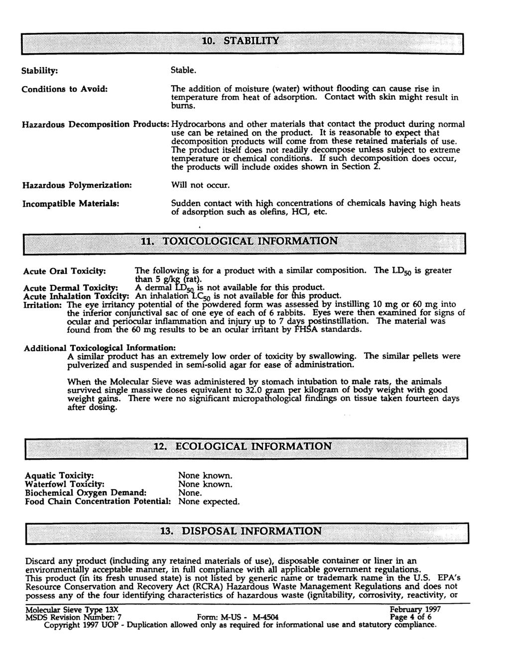
164
165
166
167
168
169
170
171
172
173
174
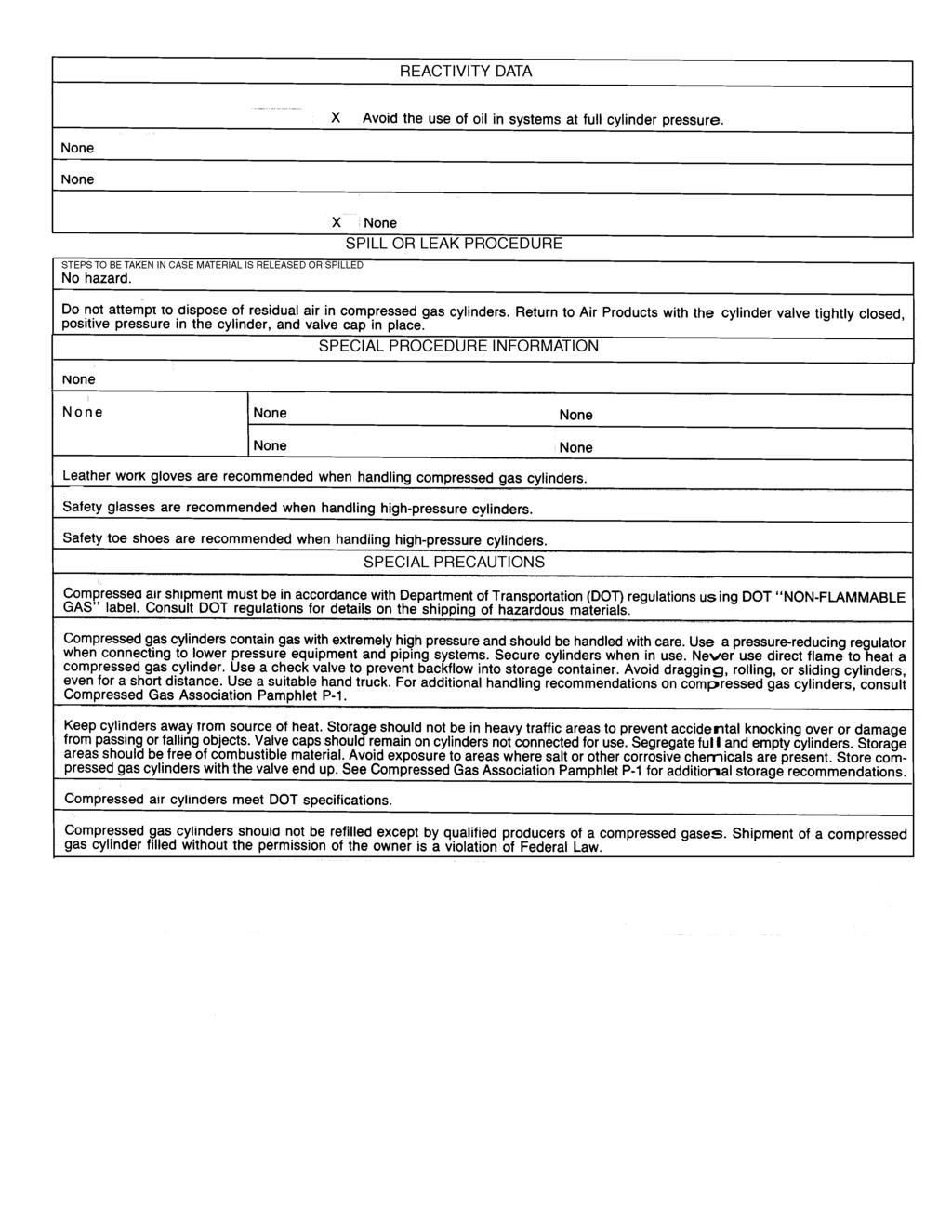
175
RAM 4021 Operation Manual
 RAM 4021 Operation Manual Worldwide Manufacturer of Gas Detection Solutions TABLE OF CONTENTS RAM 4021 For your safety...3 Description...3 Set-up mode...4 Annunciator lights/alarms...4 Operation...5 Calibration...6
Operating Manual. Models AQT-02 & AQT-COO2 Manual No. MON004 (Rev 2 April 2000)
") Models AQT-02 & AQT-COO2 Manual No. MON004 (Rev 2 April 2000) Operating Manual AIR SYSTEMS INTERNATIONAL, INC. 829 Juniper Crescent, Chesapeake, Va., 23320 Telephone (757) 424-3967 Toll Free 1-800-866-8100
Models AQT-02 & AQT-COO2 Manual No. MON004 (Rev 2 April 2000) Operating Manual AIR SYSTEMS INTERNATIONAL, INC. 829 Juniper Crescent, Chesapeake, Va., 23320 Telephone (757) 424-3967 Toll Free 1-800-866-8100
Accu-Tab Systems 1000 Series by Axiall Corporation
 Accu-Tab Systems 1000 Series by Axiall Corporation Installation and Operating Instructions Model 1050 DANGER: DO NOT MIX CHEMICALS! The Accu-Tab chlorinator is designed for use with Axiall approved tablets
User Instruction Manual
 User Instruction Manual 4500 psi Air Compressor Ver 2, 1.18 Contents Parts Included...3 Assembly Instructions...3-5 Operation Instructions...6-7 Oil Change Intervals...8 Air Filter Replacement...9 Setting
Accu-Tab Systems 2000 P Series by Axiall Corporation
 Accu-Tab Systems 2000 P Series by Axiall Corporation Installation and Operating Instructions Models 2075 P 2150 P For NSF/ANSI-Standard 61 NSF STANDARD 61 applications use NSF/ANSI Standard 60 listed Axiall
200 PSI COMPRESSORS - MODEL NUMBERS
 200 PSI COMPRESSORS - MODEL NUMBERS 380C AIR COMPRESSOR KIT PART NO. 38033 480C AIR COMPRESSOR KIT PART NO. 48043 380C 480C IMPORTANT: It is essential that you and any other operator of this product read
RAM 4021-DPX Operation Manual
 RAM 4021-DPX Operation Manual Worldwide Manufacturer of Gas Detection Solutions TABLE OF CONTENTS ABL 4021-DPX / RAM 4021-DPX For Your Safety... 3 Description... 3 Setup Mode... 4 Lights/Alarms... 4 Operation...
GETZ EQUIPMENT INNOVATORS PART NO.: 9G59554 MODEL: MS 36 SC-R HYDROSTATIC TEST PUMP
 GETZ EQUIPMENT INNOVATORS PART NO.: 9G59554 MODEL: MS 36 SC-R HYDROSTATIC TEST PUMP LIMITED WARRANTY Getz Equipment Innovators warrants its products, and component parts of any product manufactured by
RAM Operation Manual. Worldwide Manufacturer of Gas Detection Solutions
 RAM 4021 Operation Manual Worldwide Manufacturer of Gas Detection Solutions TABLE OF CONTENTS RAM 4021 For Your Safety... 2 Description.... 2 Setup Mode.... 2 Lights/Alarms.... 3 Operation.... 4 Calibration....
42045 Heavy Duty ADA Base Model Kit: 85/105 PSI (ADA Compressor Only) Heavy Duty ADA Base Model Kit: 110/145 PSI (ADA Compressor Only)
 Heavy Duty ADA Base Model Kit: 110/145 PSI (ADA Compressor Only)") 42045 Heavy Duty ADA Base Model Kit: 85/105 PSI (ADA Compressor Only) 42047 Heavy Duty ADA Base Model Kit: 110/145 PSI (ADA Compressor Only) 45052 Constant Duty ADA Base Model Kit: 85/105 PSI (ADA Compressor
42045 Heavy Duty ADA Base Model Kit: 85/105 PSI (ADA Compressor Only) 42047 Heavy Duty ADA Base Model Kit: 110/145 PSI (ADA Compressor Only) 45052 Constant Duty ADA Base Model Kit: 85/105 PSI (ADA Compressor
100C Air Compressor Kit
 10010 100C Air Compressor (standard mounting bracket, CE Spec) 10014 100C Air Compressor (no leader hose or check valve, CE Spec) 10016 100C Air Compressor (with Omega Bracket, CE Spec) IMPORTANT: It is
Calera Fire Department Breathing Air System Technical Specifications
 Calera Fire Department Breathing Air System Technical Specifications I. General Arrangement The air compressor system shall be a turnkey, packaged appliance designed to deliver high pressure breathing
RAM Operation Manual. Worldwide Manufacturer of Gas Detection Solutions
 RAM 4021 Operation Manual Worldwide Manufacturer of Gas Detection Solutions TABLE OF CONTENTS RAM 4021 For Your Safety... 2 Description.... 2 Setup Mode.... 2 Lights/Alarms.... 3 Operation.... 4 Calibration....
NB/NBR NITROGEN BOOSTER FOR AVIATION SERVICE
 NB/NBR NITROGEN BOOSTER FOR AVIATION SERVICE INSTALLATION, OPERATION & MAINTENANCE MANUAL INTERFACE DEVICES, INC. 230 Depot Road, Milford, CT 06460 Ph: (203) 878-4648, Fx: (203) 882-0885, E-mail: info@interfacedevices.com
INSTALLATION. and INSTRUCTION MANUAL. for QUALITY AIR BREATHING SYSTEMS. Model 50-P-Mini Portable Systems Outfitted with ABM-725 Monitor
 INSTALLATION and INSTRUCTION MANUAL for QUALITY AIR BREATHING SYSTEMS Model 50-P-Mini Portable Systems Outfitted with ABM-725 Monitor M A R T E C H S E R V I C E S C O M P A N Y P.O. Box 7079 OFFICE: (507)
RAM 4021-PR. Operation Manual. Worldwide Manufacturer of Gas Detection Solutions
 RAM 4021-PR Operation Manual Worldwide Manufacturer of Gas Detection Solutions TABLE OF CONTENTS RAM 4021-PR For Your Safety... 2 Description.... 2 Setup Mode.... 2 Lights/Alarms.... 3 Operation.... 4
200 PSI FAST-FILL AIR SOURCE KIT
 200 PSI FAST-FILL AIR SOURCE KIT 55% Duty Compressor on 2.0 Gallon Air Tank PART NO. 20007 IMPORTANT: It is essential that you and any other operator of this product read and understand the contents of
IMPORTANT SAFETY INSTRUCTIONS
 IMPORTANT SAFETY INSTRUCTIONS CAUTION - To reduce risk of electrical shock: - Do not disassemble. Do not attempt repairs or modifications. Refer to qualified service agencies for all service and repairs.
420C AIR COMPRESSOR KIT PART NO C AIR COMPRESSOR KIT PART NO
 420C AIR COMPRESSOR KIT PART NO. 42042 460C AIR COMPRESSOR KIT PART NO. 46043 420C 460C IMPORTANT: It is essential that you and any other operator of this product read and understand the contents of this
MODEL NUMBER: PSI AIR SOURCE KIT 200 PSI Compressor on 2.0 Gallon 200 PSI Air Tank
 IMPORTANT SAFETY INSTRUCTIONS CAUTION - To reduce risk of electrical shock or Electrocution: MODEL NUMBER: 20008 200 PSI AIR SOURCE KIT 200 PSI Compressor on 2.0 Gallon 200 PSI Air Tank IMPORTANT: It is
RAM Operation Manual
 RAM 4021-1 Operation Manual Worldwide Manufacturer of Gas Detection Solutions TABLE OF CONTENTS RAM 4021-1 For Your Safety... 2 Description... 2 Setup Mode... 3 Lights/Alarms... 3 Operation... 4 Calibration...
MODEL NUMBER: M20005 AIR SOURCE KIT. 30% Duty Compressor on. 2.0 Gallon Air Tank SAVE THIS MANUAL FOR FUTURE REFERENCE
 MODEL NUMBER: M20005 AIR SOURCE KIT 30% Duty Compressor on 2.0 Gallon Air Tank SAVE THIS MANUAL FOR FUTURE REFERENCE USER MANUAL IMPORTANT SAFETY INSTRUCTIONS CAUTION - To reduce risk of electrical shock
200 PSI HIGH-FLOW AIR SOURCE KIT
 200 PSI HIGH-FLOW AIR SOURCE KIT 50% Duty Compressor on 2.0 Gallon Air Tank PART NO. 20008 IMPORTANT: It is essential that you and any other operator of this product read and understand the contents of
Operating Manual. Model BAC-30RT30/BAC-30DC
 Model BAC-30RT30/BAC-30DC Manual No. BAC012 (Rev 1 October 2002) Operating Manual AIR SYSTEMS INTERNATIONAL, INC. 829 Juniper Crescent, Chesapeake, Va., 23320 Telephone (757) 424-3967 Toll Free 1-800-866-8100
444C DUAL PERFORMANCE VALUE PACK
 (Chrome) PART NO. 44432 IMPORTANT: It is essential that you and any other operator of this product read and understand the contents of this manual before installing and using this product. SAVE THIS MANUAL
Acid- Rite ph Adjustment System 2500 by Axiall, a Westlake Company
 Acid- Rite ph Adjustment System 2500 by Axiall, a Westlake Company Installation and Operating Instructions DANGER: DO NOT MIX CHEMICALS! The Acid-Rite ph Adjustment System is designed for use with Axiall
SERVICE MANUAL MODEL BA050BMST BREATHING AIR PANEL
 www.modsafe.com SERVICE MANUAL MODEL BA050BMST BREATHING AIR PANEL WARNING: Do not attempt to operate this equipment without first reading and understanding the service manual enclosed with this device.
400C & 450C DUAL PERFORMANCE VALUE PACKS
 (Chrome) PART NO. 40013 (Silver) PART NO. 45012 (Chrome) PART NO. 45013 IMPORTANT: It is essential that you and any other operator of this product read and understand the contents of this manual before
SERVICE MANUAL MODEL BA600AMST-S1 BREATHING AIR PANEL
 SERVICE MANUAL MODEL BA600AMST-S1 BREATHING AIR PANEL WARNING: Do not attempt to operate this equipment without first reading and understanding the service manual enclosed with this device. 2/05 GENERAL
Installation Instructions Air Compressor Part # 2780, 2781
 Note: It is essential that the operator of this product read and understand the contents of this manual before installing and using this product. Parts Included Qty Parts Included Qty Compressor 1 Coil
120 PSI FAST-FILL AIR SOURCE KIT 25% Duty Compressor on 1.5 Gallon Air Tank
 120 PSI FAST-FILL AIR SOURCE KIT 25% Duty Compressor on 1.5 Gallon Air Tank PART NO. 20003 IMPORTANT: It is essential that you and any other operator of this product read and understand the contents of
AC1810 / AC1810-A TECHNICAL SPECIFICATIONS. Operating Pressure psi ( kgs/cm²) [AC1810] Displacement. Net Weight
![AC1810 / AC1810-A TECHNICAL SPECIFICATIONS. Operating Pressure psi ( kgs/cm²) [AC1810] Displacement. Net Weight](/thumbs/83/88369739.jpg "AC1810 / AC1810-A TECHNICAL SPECIFICATIONS. Operating Pressure psi ( kgs/cm²) [AC1810] Displacement. Net Weight") Technical Specifications Operating Instructions Maintenance Information Troubleshooting Guide Parts Diagrams AC1810 / AC1810-A THE EVOLUTION OF PERFECTION CAUTION: Before attempting to use or service this
Technical Specifications Operating Instructions Maintenance Information Troubleshooting Guide Parts Diagrams AC1810 / AC1810-A THE EVOLUTION OF PERFECTION CAUTION: Before attempting to use or service this
250C-IG COMPRESSOR KIT 12V PART NO C-IG COMPRESSOR KIT 24V PART NO
 250C-IG COMPRESSOR KIT 12V PART NO. 25050 250C-IG COMPRESSOR KIT 24V PART NO. 25058 IMPORTANT: It is essential that you and any other operator of this product read and understand the contents of this manual
250C-IG COMPRESSOR KIT 12V PART NO C-IG COMPRESSOR KIT 24V PART NO
 250C-IG COMPRESSOR KIT 12V PART NO. 25050 250C-IG COMPRESSOR KIT 24V PART NO. 25058 IMPORTANT: It is essential that you and any other operator of this product read and understand the contents of this manual
AIR COMPRESSOR OPERATING INSTRUCTION AND PARTS LIST
 AIR COMPRESSOR OPERATING INSTRUCTION AND PARTS LIST OIL-LESS TYPE IMPORTANT: PLEASE READ CAREFULLY BEFORE STARTING OPERATIONS. THE CONTENTS ARE FOR GENERAL INFORMATION OF ALL THE SIMILAR MODELS. Record
97C COMPRESSOR KIT 12V PART NO C COMPRESSOR KIT 24V PART NO C COMPRESSOR KIT PART NO
 97C COMPRESSOR KIT 12V PART NO. 00097 97C COMPRESSOR KIT 24V PART NO. 02497 98C COMPRESSOR KIT PART NO. 00098 97C 98C IMPORTANT: It is essential that you and any other operator of this product read and
Mobile Breathing Air Systems
 FAMA BUYER S GUIDE TC053 Prepared by the FAMA Body Subcommittee This guide does not endorse any manufacturer or product Page 1 of 14 Contents Introduction... 3 Overview... 4 Mobile Breathing Air System
Model PSI Compressor with 3-Gallon Air Tank 12VDC
 Model 6350 150 PSI Compressor with 3-Gallon Air Tank 12VDC IMPORTANT: It is essential that you and any other operator of this product read and understandd the contents of this manual before installing
PC1131 Electric Air Compressor
 Senco Products Inc. 8485 Broadwell Road Cincinnati, Ohio 45244 PC1131 Electric Air Compressor Operating Instructions C US 2006, 2007 by Senco Products, Inc. Warnings for the safe use of this tool are included
WATER HEATER THERMAL EXPANSION TANKS Owner s Manual. Safety Instructions Installation Maintenance Warranty. Models: 2-5 Gallon Capacity
 WATER HEATER THERMAL EXPANSION TANKS Owner s Manual Safety Instructions Installation Maintenance Warranty Models: 2-5 Gallon Capacity Thank You for purchasing this Thermal Expansion Tank. Properly installed
accidents which arise due to non-observance of these instructions and the safety information herein.
 3 GALLON PANCAKE COMPRESSOR Model: 50959 CALIFORNIA PROPOSITION 65 WARNING: You can create dust when you cut, sand, drill or grind materials such as wood, paint, metal, concrete, cement, or other masonry.
Budget Range Operators Handbook
 Budget Range Operators Handbook BAMBI AIR COMPRESSORS LTD 152 Thimble Mill Lane Heartlands Birmingham B7 5HT United Kingdom Tel: 0121 322 2299 Fax: 0121 322 2297 Email: sales@bambi-air.co.uk www.bambi-air.co.uk
E2K-L. Liquid Level Sensor That Is Unaffected by the Color of the Pipe or Liquid. Liquid Level Sensor. Ordering Information
 Liquid Level EK-L CSM_EK-L_DS_E 3 Liquid Level That Is Unaffected by the Color of the or Liquid Mount to bypass pipes. Fit a wide range of pipe diameters: 8 to mm or to mm Built-in Amplifiers to save space.
NGP-250/500 Nitrogen Generator Quick Start Guide
 NGP-250/500 Nitrogen Generator Quick Start Guide Version: A July 2013 Potter Electric Signal Company, LLC 5757 Phantom Dr., Suite 125 P. O. Box 42037 Hazelwood, MO 63042 Phone: (314) 595-6900 Document
J Air and Water Kit Instructions Part# 02584
 J Air and Water Kit Instructions Part# 02584 Unpacking Please open and inspect your package upon receipt. Your package was packed with great care and all the necessary packing materials to arrive to you
450P AUTOMATIC PORTABLE COMPRESSOR EXTREME SERIES
 EXTREME SERIES PART NO. 45043 IMPORTANT: It is essential that you and any other operator of this product read and understand the contents of this manual before installing and using this product. SAVE THIS
MP15 Jockey Pump Controller
 Setup and Operating Instructions MP15 Jockey Pump Controller This manual provides general information, installation, operation, maintenance, and system setup information for Metron Model MP15 Jockey Pump
R E D I C O N T R O L S
 R E D I C O N T R O L S Operation & Maintenance Manual Portable Service Purger for Low Pressure Chillers Model: PSP-LP-1B For Refrigerants R-11, R-113, R-114 & R-123 & Other Similar Refrigerants File Literature
480C DUAL PERFORMANCE VALUE PACK
 (Pewter) PART NO. 48012 (Chrome) PART NO. 48032 (Stealth Black) PART NO. 48042 IMPORTANT: It is essential that you and any other operator of this product read and understand the contents of this manual
CSA Sample Draw Aspirator Adapter Operator s Manual
 30-0951-CSA Sample Draw Aspirator Adapter Operator s Manual Part Number: 71-0367 Revision: 0 Released: 4/30/15 www.rkiinstruments.com WARNING Read and understand this instruction manual before operating
MODEL NUMBER: P-A AUTOMATIC PORTABLE COMPRESSOR
 MODEL NUMBER: 45043-450P-A AUTOMATIC PORTABLE COMPRESSOR IMPORTANT: It is essential that you and any other operator of the product read and understand the contents of this manual before installing and
PERSONAL AIR BREATHING UNIT
 PERSONAL AIR BREATHING UNIT Operation & Maintenance Manual MARTECH SERVICES C O M P A N Y 1-800-831-1525 Table of Contents INTRODUCTION: Page 2 COMPONENTS DRAWING: Page 3 START UP: Page 4 OPERATION: Page
Interface Devices, Inc. Hydraulic Mini Mule
 Interface Devices, Inc. Hydraulic Mini Mule INSTALLATION, OPERATION & MAINTENANCE MANUAL IMPORTANT! FILE THIS MANUAL IN A SAFE PLACE FOR FUTURE SERVICE & PARTS NEEDS ALWAYS REFERENCE THE SERIAL NUMBER
Breathing Air Compressor Bid Specification
 Breathing Air Compressor Bid Specification The system shall be designed as a complete breathing air package, made up of an air compressor module, air storage and breathing apparatus cylinder charge station.
D Series Air and Water Kit Part# 02550
 D Series Air and Water Kit Part# 02550 Unpacking Please open and inspect your package upon receipt. Your package was packed with great care and all the necessary packing materials to arrive to you undamaged.
MODEL 840 AIR HYDRAULIC PUMP INSTRUCTION
 MODEL 840 AIR HYDRAULIC PUMP INSTRUCTION Jackco Transnational Inc. 202 South El Monte, CA 888-452-2526 www.jackco.com FOR YOUR SAFETY Read all instructions, warnings and cautions carefully. Follow all
IMPORTANT SAFETY INSTRUCTIONS
 IMPORTANT SAFETY INSTRUCTIONS CAUTION - To reduce risk of electrical shock or electrocution: - Do not disassemble. Do not attempt repairs or modifications. Refer to qualified service agencies for all service
MODEL CALIBRATION GAS DELIVERY SYSTEM
 MODEL 1200-26 CALIBRATION GAS DELIVERY SYSTEM Sierra Monitor Corporation 1991 Tarob Court, Milpitas, CA 95035 (408) 262-6611 MODEL 1200-26 CALIBRATION GAS DELIVERY SYSTEM APPLICABILITY & EFFECTIVITY This
SDS -Series 4C-D201/-D202 Supplemental Drying System User s Manual
 SDS -Series 4C-D201/-D202 Supplemental Drying System User s Manual 8 Executive Drive P.O. Box 2105 Toms River, NJ 08754 (732) 244-0010 (800) 337-3762 fax (732) 244-8140 www.permapure.com info@permapure.com
400H HARDMOUNT AIR COMPRESSOR KIT PART NO H HARDMOUNT AIR COMPRESSOR KIT PART NO
 400H HARDMOUNT AIR COMPRESSOR KIT PART NO. 40042 450H HARDMOUNT AIR COMPRESSOR KIT PART NO. 45042 400H 450H IMPORTANT: It is essential that you and any other operator of this product read and understand
OPERATING INSTRUCTIONS Pressure Control System PCS-20 through PCS-100
 107 W. Main Street Worthington, PA 16262 Phone: 724.297.3416 Fax: 724.297.5189 http://www.airtak.com OPERATING INSTRUCTIONS Pressure Control System PCS-20 through PCS-100 12-2007 TABLE OF CONTENTS PAGE
JORDAIR/BAUER Service Manual
 JORDAIR/BAUER Service Manual Breathing Air Compressor Maintenance Log Doc. ServiceManual Page - 1 SAFETY RELEASE-2016 The following document is prepared to ensure safety of operators and service technicians.
450P- RV AUTOMATIC PORTABLE COMPRESSOR EXTREME SERIES
 450P- RV AUTOMATIC PORTABLE COMPRESSOR EXTREME SERIES PART NO. 45053 IMPORTANT: It is essential that you and any other operator of this product read and understand the contents of this manual before installing
Accu-Tab PowerBase 3070AT by Axiall Corporation
 Accu-Tab PowerBase 3070AT by Axiall Corporation Installation and Operating Instructions The PowerBase 3070AT Chlorinator is NSF STD 50 NSF-Listed for pool applications. ONLY Axiall Corp. Accu-Tab Blue
TOP VALVE. Pat. #5,857,486 & 5,944,050. Mid-Range Pressure PSIG Back Pressure and Pressure Relief Valves. Instruction Manual
 TOP VALVE Pat. #5,857,486 & 5,944,050 Mid-Range Pressure 50 232 PSIG Back Pressure and Pressure Relief Valves Instruction Manual Please Note: This instruction manual provides detailed information and instructions
ULTRA-LIGHT DUTY ONBOARD AIR SYSTEM
 ULTRA-LIGHT DUTY ONBOARD AIR SYSTEM PART NO. 10000 IMPORTANT: It is essential that you and any other operator of this product read and understand the contents of this manual before installing and using
TECHNICAL DATA MAINTENANCE AIR COMPRESSOR MODEL G-1
 Dry 131h 1. DESCRIPTION The Viking Model G-1 Maintenance Air Compressor is an electric motor-driven, aircooled, single-stage, oil-less compressor. The unit is equipped with a check valve and provides a
SPECIFICATIONS Type: Twin stack, single phase Tank: 4 gallon Air Output: PSI; PSI Max PSI: 125 PSI HP: 1.
 2 GALLON TWIN STACK AIR COMPRESSOR Model: 9526 DO NOT RETURN TO STORE. Please CALL 800-348-5004 for parts and service. CALIFORNIA PROPOSITION 65 WARNING: You can create dust when you cut, sand, drill or
Accu-Tab PowerBase 3012AT by Axiall Corporation
 Accu-Tab PowerBase 3012AT by Axiall Corporation Installation and Operating Instructions DANGER: DO NOT MIX CHEMICALS! The PowerBase 3012AT chlorinator system is designed for use with Axiall Corp. approved
Installation and Operation 370ESP (Electric Single-Point Purger) & 370ESPR (Retrofit Purger)
 & 370ESPR (Retrofit Purger)") IB-77 Installation and Operation 370ESP (Electric Single-Point Purger) & 370ESPR (Retrofit Purger) These installation, operation and technical instructions should be used by experienced personnel as a
IB-77 Installation and Operation 370ESP (Electric Single-Point Purger) & 370ESPR (Retrofit Purger) These installation, operation and technical instructions should be used by experienced personnel as a
SERVICE MANUAL MODEL BA100BMST 100 SCFM PORTABLE AIR PANEL
 Product Manual MST Portable Air Filtration System SERVICE MANUAL MODEL BA100BMST 100 SCFM PORTABLE AIR PANEL WARNING: Do not attempt to operate this equipment without first reading and understanding the
OPERATION MANUAL NTF-15
 OPERATION MANUAL NTF-15 Nitrogen Tire Filling Valve Stem Caps (Qty=200) Order P/N 436075 RTI Technologies, Inc 10 Innovation Drive York, PA 17402 800-468-2321 www.rtitech.com 035-81235-00 (Rev B) TABLE
User's Manual. Heavy Duty Dissolved Oxygen Meter. Model
 User's Manual Heavy Duty Dissolved Oxygen Meter Model 407510 Introduction Congratulations on your purchase of Extech's Heavy Duty Dissolved Oxygen / Temperature Meter which simultaneously displays Dissolved
Pressure Relief Valve Instruction Manual
 CVR3-M0_062017 Pressure Relief Valve Instruction Manual MODEL: CVR3 SFA Companies 10939 N. Pomona Ave. Kansas City, MO 64153 Tel: 888-332-6419 * Fax: 816-448-2142 E-mail: sales@bvahydraulics.com Website:
HAYWARD FLOW CONTROL Series PBV Back Pressure Valve and Series RPV Pressure Relief Valve INSTALLATION, OPERATION, AND MAINTENANCE INSTRUCTIONS
 HAYWARD FLOW CONTROL Series PBV Back Pressure Valve and Series RPV Pressure Relief Valve INSTALLATION, OPERATION, AND MAINTENANCE INSTRUCTIONS Page 1 of 20 Page 2 of 20 TABLE OF CONTENTS Safety Warnings
Operation Manual. O2 Quickstick. Oxygen Analyzer 08.17
 Operation Manual O2 Quickstick Oxygen Analyzer 08.17 If you have any questions on this equipment please contact Technical Support at: Nuvair 1600 Beacon Place Oxnard, CA 93033 Phone: 805-815-4044 FAX:
MODEL NUMBER: P PORTABLE COMPRESSOR
 MODEL NUMBER: 44043-440P PORTABLE COMPRESSOR IMPORTANT: It is essential that you and any other operator of the product read and understand the contents of this manual before installing and using this product.
3 GALLON, OILLESS PANCAKE COMPRESSOR INSTRUCTIONS. Item #31289
 3 GALLON, OILLESS PANCAKE COMPRESSOR INSTRUCTIONS Item #31289 The EASTWOOD 3 GALLON, OILLESS PANCAKE COMPRESSOR, with an Integral Air Regulator, efficiently supplies all compressed air requirements for
INSTRUCTION MANUAL. FLOW CONTROL DRAWERS MANUAL / PLC CONTROL SERIES Model Version Perma Pure LLC Tel:
 PERMA PURE INSTRUCTION MANUAL FLOW CONTROL DRAWERS MANUAL / PLC CONTROL SERIES Model 3300 Version 4.06 Perma Pure LLC Tel: 732-244-0010 P.O. Box 2105, 8 Executive Drive Tel: 800-337-3762 (toll free US)
OPERATION MANUAL NTF-60 Plus
 OPERATION MANUAL NTF-60 Plus Nitrogen Tire Filling Valve Stem Caps (Qty=200) Order P/N 436075 RTI Technologies, Inc 10 Innovation Drive York, PA 17402 800-468-2321 www.rtitech.com 035-81264-00 (Rev A)
SPECIFICATIONS TABLE Maximum Air Pressure 115 PSI Air Tank Capacity 20 Gallons
 SPECIFICATIONS TABLE Maximum Air Pressure 115 PSI Air Tank Capacity 20 Gallons Air Flow Capacity 6.2 CFM at 40 PSI 5.2 CFM at 90 PSI Motor 2.5 HP Working / 4 HP Peak 120 Volt / 60 Hz / 13 A / 1-Phase Required
TOP VALVE. Pat. #5,857,486 & 5,944,050. High Temperature: max. 300 F (149 C) Back Pressure And Pressure Relief Valves. Instruction Manual
 Back Pressure And Pressure Relief Valves. Instruction Manual") TOP VALVE Pat. #5,857,486 & 5,944,050 High Temperature: max. 300 F (149 C) Back Pressure And Pressure Relief Valves Instruction Manual PLEASE NOTE: This instruction manual provides information and instructions
TOP VALVE Pat. #5,857,486 & 5,944,050 High Temperature: max. 300 F (149 C) Back Pressure And Pressure Relief Valves Instruction Manual PLEASE NOTE: This instruction manual provides information and instructions
2 Gallon Air Compressor
 Table of Contents Topic Page 2 Gallon Air Compressor Safety Guidelines-Definitions 4 Hazard Warnings 5 Air Compressor 15 Precautions 15 Basic Air Compressor Components 16 Assembling the Air Compressor
Operating Manual CBA Series Cascade Breathing Air Assemblies
 Manual No. WHP002 (Rev 5 January 2007) Operating Manual CBA Series Cascade Breathing Air Assemblies AIR SYSTEMS INTERNATIONAL, INC. 829 Juniper Crescent, Chesapeake, Va., 23320 Telephone (757) 424-3967
MODEL NUMBER: P PORTABLE COMPRESSOR
 MODEL NUMBER: 30033-300P PORTABLE COMPRESSOR IMPORTANT: It is essential that you and any other operator of the product read and understand the contents of this manual before installing and using this product.
2 GAL AIR COMPRESSOR OPERATOR S MANUAL 1/3HP/2-GALLON IMPORTANT: READ THIS OPERATOR S MANUAL BEFORE USING
 ITEM# AT01101 SKU# 207-1525 OPERATOR S MANUAL 1/3HP/2-GALLON 2 GAL AIR COMPRESSOR IMPORTANT: READ THIS OPERATOR S MANUAL BEFORE USING Toll Free Helpline: 1-888-899-0146 Versions 01 TABLE OF CONTENTS SAFETY
VERTICAL AIR COMPRESSORS
 VERTICAL AIR COMPRESSORS MODEL NO: VE15C150, VE18C150, VE25C150 PART NO: 2226010, 2226020, 2226025 OPERATION & MAINTENANCE INSTRUCTIONS LS0715 INTRODUCTION Thank you for purchasing this CLARKE Vertical
Owners Manual Models: 075-AQF-CX. Aquatrol Backwashing Catalytic Carbon Filter. Visit us online at.
 Visit us online at www.uswatersystems.com Aquatrol Backwashing Catalytic Carbon Filter Owners Manual Models: 075-AQF-CX REVISION # 1.0 REVISION DATE October 11, 2017 US Water Systems, Inc. 1209 Country
HAYWARD FLOW CONTROL TFS SERIES FLOW METER INSTALLATION, OPERATION AND MAINTENANCE INSTRUCTIONS
 HAYWARD FLOW CONTROL TFS SERIES FLOW METER INSTALLATION, OPERATION AND MAINTENANCE INSTRUCTIONS PLEASE READ THE FOLLOWING INFORMATION PRIOR TO INSTALLING AND USING HAYWARD TFS SERIES FLOW METERS. FAILURE
Universal Valve Company Inc
 Universal Valve Company Inc 800-223-0741 www.universalvalve.com 1975-FA34 (Air Tower Troubleshooting Manual) Overview This manual has been arranged as a tool for diagnosing, and repairing Free Air Universal
Operation Manual. O2 Quickstick. Oxygen Analyzer
 Operation Manual O2 Quickstick Oxygen Analyzer 01.11 www.nuvair.com If you have any questions on this equipment please contact Technical Support at: Nuvair 2949 West 5 th St. Oxnard, CA 93030 Phone: 805-815-4044
NTO-200 Operation Manual
 NTO-200 Operation Manual MAHLE Service Solutions 10 Innovation Drive York, PA 17402 USA Phone: 717-840-0678 Visit www.servicesolutions.mahle.com for the most up to date information. 035 81679 00 (Rev B)
AMP Oil Free Manual AMP 50-8-TC AMP 50-6-D AMP General User and Maintenance Instructions
 AMP Oil Free Manual AMP 50-8-TC AMP 50-6-D AMP 50-24 General User and Maintenance Instructions Silentaire Technology 8614 Veterans Memorial Dr. Houston, TX 77088 800-972-7668 Fax 832-327-0669 www.silentaire.com
INSTRUCTIONS FOR MODELS SG3897 AND SG3898 CROSS PURGE ASSEMBLIES
 INSTRUCTIONS FOR MODELS SG3897 AND SG3898 CROSS PURGE ASSEMBLIES THIS BOOKLET CONTAINS PROPRIETARY INFORMATION OF ADVANCED SPECIALTY GAS EQUIPMENT CORP. AND IS PROVIDED TO THE PURCHASER SOLELY FOR USE
RK-IR Sample Draw Aspirator Adapter Operator s Manual
 30-0951RK-IR Sample Draw Aspirator Adapter Operator s Manual Part Number: 71-0018RK Revision: A Released: 6/2/10 www.rkiinstruments.com Product Warranty RKI Instruments, Inc. warrants gas alarm equipment
Installation and operating manual. Pneumatic control station LK product no: PCS 1-10
 LK product no: PCS 1-10 Article no: 74503 Revision:8 Article no: 74503 Revision: 8 2 (23) Contents 1. General information... 5 2. Safety precautions... 5 2.1 Significance of symbols... 5 2.2 Explanatory
BS Series Basket Strainer
 BS Series Basket Strainer Operating, Installation, & Maintenance Manual Corrosion Resistant Fluid and Air Handling Systems. Dated 04-26-12 PRESSURE DROP SIMTECH strainers are engineered to offer the lowest
MODEL 100 NITROGEN INFLATION CART
 MODEL 100 NITROGEN INFLATION CART Installation & Operation Information Branick Industries, Inc. 4245 Main Avenue P.O. Box 1937 Fargo, North Dakota 58103 REV120106 P/N: 81-0113 TABLE OF CONTENTS SAFETY
Marschalk Model # 94000
 Marschalk Model # 94000 12-volt DC Portable oil-less Air Compressor Operation Manual 27250006 REV 1 9/13/05 Table of Contents CHAPTER 1: SYSTEM DESCRIPTION... 5 FUNCTION AND THEORY... 5 SYSTEM COMPONENTS...
SSFU SUPER SPRAYFAST UNIVERSAL ADHESIVE APPLICATOR
 S S F U SSFU SUPER SPRAYFAST UNIVERSAL ADHESIVE APPLICATOR MACHINERY DIVISION OWNER S MANUAL UNIT INSTRUCTIONS Please follow all SSFU Safety Instructions. Contact your Duro Dyne Tech Service if you have