INSTALLATION GUIDE MODEL NUMBER X. UniMaxx-Plus-SC-500-AC-V3 UNIMAXX SOLAR PUMP STATION
|
|
|
- Elinor Atkins
- 5 years ago
- Views:
Transcription


1 INSTALLATION GUIDE UNIMAXX SOLAR PUMP STATION MODEL NUMBER X UniMaxx-Plus-SC-500-AC-V3
2 Table of Contents For Your Safety About This Manual Designated Use Qualification of the Installer Hand-Over of the System (Specialist) General Safety Instructions General Instructions Regarding Solar Fluid 3 2 Description Of The Product 6 3 Assembly and Installation (Specialist) Commissioning (Specialist) Flushing and FIlling the Solar Circuit (Specialist) Preparation for Flushing (Specialist) Flushing and FIlling (Specialist) Setting the Solar Thermal System (Specialist) 9 5 Cleaning Maintenance and Decommissioning (Specialist) Partial Draining of the Solar Installation (Specialist) Complete Draining of the Solar Installation (Specialist) Replacing the Pump (Specialist) Replacing the Gaskets in the Solar Station (Specialist) Dismounting (Specialist) 14 7 Application Range of the Check Valves (Specialist) 17 8 Spare Parts (Specialist) 19 9 Technical Data and Pressure Drop Characteristics Commissioning Log 22
3 1. For Your Safety Carefully read this manual before installation and commissioning. Non-observance of the instructions in this manual may lead to serious material damage and serious injuries that may result in death. > Keep this manual in close proximity of the system for later use. NOTICE WARNING CAUTION indicates that there is risk of death, serious injuries or considerable material damage if suitable safety precautions are not taken. indicates that there is a risk of light injuries if suitable safety precautions are not taken. indicates that there is a risk of material damage if suitable safety precautions are not taken. 1.1 ABOUT THIS MANUAL This manual describes the function, installation, commissioning and operation of the UniMaxx solar pump station. The chapters called [specialist] are only addressed to specialists. For other components of the solar installation, such as collectors, storage tanks, expansion tanks, and controllers, please refer to the instructions of the corresponding manufacturer. 1.2 DESIGNATED USE The solar station is a pre-assembled fitting assembly checked for tightness and used for recirculating the solar fluid in the solar circuit. The solar station must only be used in solar thermal systems as pumping station in the solar circuit, taking into consideration the technical limit values indicated in this manual. The station may only be assembled indoors. The station must be assembled and operated as described in this manual! Using the station contrary to its designated use will invalidate all liability claims. Only use original accessories. 1.3 QUALIFICATION OF THE INSTALLER Installation and commissioning of this equipment should be done by qualified installers [specialist] in accordance with local, state and federal codes which may be applicable. The following must also be observed during installation and commissioning: Relevant regional and national regulations (for example Occupational Safety and Health Act) Relevant accident prevention regulations (for example of the Employer s Liability Insurance Association) Instructions and safety instructions mentioned in this manual
4 1.4 HAND-OVER OF THE SYSTEM (SPECIALIST) After installation and commissioning, the installer is responsible for familiarizing the end user with the functions of the system and the basic safety measures. > After commissioning, fill in the log on the last page of this manual. > Hand the manual over to the end user. Instruct the end user to keep the manual in close proximity to the system. > Instruct the end user to have the solar station serviced and repaired by a specialist only. The controller settings must not be changed by the end user. > Explain to the end user the function of the system and of the safety devices. Point out to the end user that the shell must remain mounted during operation and that the ball valves with temperature gauges and the ball valve in the flowmeter must be open. 1.5 GENERAL SAFETY INSTRUCTIONS Before installing and commissioning the product, you must read and observe the following safety instructions: WARNING Danger of scalding due to escaping vapor! If the system pressure is too high, hot solar fluid will escape from the pressure relief valves and can result in scalding. > Flush and fill the system only if the collector temperatures are below 150 F (70 C). > Connect a discharge line to the safety assembly. Observe the instructions regarding the pressure relief valve. > The pressures calculated by the installation planner for the expansion tank and the operating pressure of the installation must be set. CAUTION Risk of burns! The valves and fittings and the pump may heat up to more than 212 F (100 C) during operation. > The shell must remain closed during operation. CAUTION Personal injury and material damage caused by excess pressure! Closing both ball valves will disconnect the safety assembly from the heat exchanger. Heating the storage tank can result in the formation of high pressures, which may lead to material damage and personal injury! > In operation, the ball valves with temperature gauges and the ball valve at the flowmeter must always be open. > Close the ball valves only when service is required.
5 NOTICE Material damage due to mineral oils! Mineral oil products permanently damage the EDPM sealing elements, resulting in a loss of their sealing characteristics. We cannot be held liable for damage caused by seals thus damaged, nor will we offer a replacement under warranty. > It is imperative to prevent the EPDM sealing elements from making contact with substances containing mineral oils. > Use silicone- or polyalkylene-based lubricants free of mineral oil, such as Unisilikon L250L and Syntheso Glep 1 from the company Klüber or a silicone spray. 1.6 GENERAL INSTRUCTIONS REGARDING SOLAR FLUID WARNING Proylene glycol: hazardous in case of ingestion! Propylene glycol is hazardous in case of ingestion. It is irritant in case of eye or skin contact. > Wear chemical resistant protective gloves and safety glasses with side-shields when handling propylene glycol mixtures. > Observe the instructions of the antifreeze manufacturer. It often happens that solar thermal systems cannot be completely drained after flushing. Thus, there is a risk of frost damage when flushing with water. Therefore, the solar thermal system should only be flushed and filled with the solar fluid used later on. Strictly follow the instructions of the antifreeze manufacturer for operating a solar thermal system. All components in the solar station are resistant to a percentage of propylene glycol of up to 50%. Determine quantity according to system volume. See instructions of the collectors, storage tank and expansion tank.


6 2. Description of the Product The solar station is mounted on a wall support and held by clip springs. The station contains important valves and fittings and safety equipment for operating a solar thermal system: 1.1 Return to the collector field 1.2 Ball valve with temperature gauge in the return equipped with replaceable spindle (blue) 1.3 Pressure relief valve, 87 psi / 6 bar 1.4 Fill valve 1.5 Connection for the expansion tank 1.6 Pressure gauge 87 psi / 6 bar 2 Solar pump 3.1 Ball valve in flowmeter 3.2 Drain valve 3.3 Flowmeter 3.4 Return from the storage tank 4.1 Supply to the storage tank 4.2 Airstop equipped with manual bleeder 5.2 Ball valve with temperature gauge in the supply equipped with replaceable spindle (red) 5.1 Supply from the collector field
7 3. Assembly and Installation (Specialist) The solar station may only be installed indoors with a power supply of 120 V / 60 Hz. The installation site must be dry, stable and frost-free. NOTICE Material damage due to high temperatures! Since the solar fluid may be very hot near the collector, the fitting assembly must be installed at a sufficient distance from the collector field. > It may be necessary to install an upstream tank, in order to protect the expansion tank. 1. Remove the station from the packaging. 2. Pull off the front shell. 3. Copy the mounting holes next to the temperature gauges of the solar station to the mounting surface. 4. Drill the holes and fasten the solar station to the wall by means of the enclosed screws and, if required, the enclosed wall anchors. 5. Connect the solar station to the system by means of pipes 5 Supply from collector field 1 Return to the collector field 4 Supply to the storage tank 3 Return from the storage tank All screw connections are designed as cutting-ring compression fitting 1 male thread.
8 Assembly of the cutting-ring compression fitting: Push the union nut 2 and the cutting ring 3 onto the copper pipe 1. The pipe must protrude at least ⅛ (3 mm) from the cutting ring in order to ensure the force transmission and the sealing. Insert the support sleeve 4 into the copper pipe. Insert the copper pipe with the plugged-on individual parts (2, 3 and 4) all the way into the housing of the cutting-ring fitting 5. First screw the union nut 2 manually. Tighten the union nut 2 by rotating it by one full turn. Secure the housing of the cutting-ring fitting 5 against distortion in order to avoid damaging the sealing ring. 6. Connect a discharge line to the connection [1.3] at the pressure relief valve. Conduct the discharge line into a heat-resistant container. Secure the discharge line such that in the event of escaping vapor people in the vicinity are not put at risk. 7. Connect the connecting line for the expansion tank below the pressure gauge [1.5] and fasten the holder for the expansion tank. 8. Adapt the initial pressure of the expansion tank to the system and connect the expansion tank. Observe the manufacturer s separate instructions of the expansion tank! Also observe the layout of the installation planner. 9. Check all screw connections and retighten them, if necessary. Available As An Option WARNING Risk of electric shock! > Prior to commencing electrical work, pull the mains plug! > Only after completing all installation work, flushing and filling should the mains plug of the cotroller be plugged into a socket! This avoids an unintentional start of the motors. 10. Connect the sensors and the pump to the controller. The controller must be provided on site. Observe the separate instructions of the controller! The assembly of the solar station is now complete, and you can commission the station.
9 4. Commissioning (Specialist) Before commissioning the station, you must read and observe the following safety instructions: WARNING Danger of burns and scalding! The valves and fittings may heat up to more than 212 F (100 C). During flushing, filling and venting, the solar fluid can escape as vapor and result in scalding. > Flush and fill the system only if the collector temperatures are below 150 F (70 C). WARNING Propylene glycol: hazardous in case of ingestion! Propylene glycol is hazardous in case of ingestion. It is irritant in case of eye or skin contact. > Wear chemical resistant protective gloves and safety glasses with side-shields when handling propylene glycol mixtures. > Observe the instructions of the antifreeze manufacturer. NOTICE Risk of frost! It often happens that solar thermal systems cannot be completely drained after flushing. Thus, there is a risk of frost damage when flushing with water. NOTICE > Therefore, the solar thermal system should only be flushed and filled with the solar fluid used later on. > Use a water and propylene glycol mixture with max. 50% of propylene glycol as solar fluid, in order to avoid damaging the seals. Note regarding the commissioning sequence > When commissioning the system, first fill the storage circuit and then the solar circuit. This guarantees that any absorbed heat can also be dissipated.


![To ensure a perfect ventilation of the solar circuit, the flow velocity must be at least 0.3 m/s in the supply. 4.2 Pipe Diameter Flow Rate @ 0.3 m/s [US GPM] Flow Rate @ 0.3 m/s [l/min] 1/2 0.63 2.](/docs-images/83/88802040/images/10-2.jpg "4 3/4 1.49 5.6 The air liberated from the solar fluid is collected in the upper area of the airstop and can be discharged via the vent plug [4.2]. WARNING Danger of scalding due to escaping vapor!")
10 4.1 FLUSHING AND FILLING THE SOLAR CIRCUIT (SPECIALIST) The fill and drain connections required for flushing and filling have been integrated into the solar station. In order to flush any dirt particles that may still be present out of the system, use only flush and fill stations equipped with suitable micro filters. Ball Valve With Integrated Check Valve (Normal direction of flow in the picture: downstream) 14 mm 0 O 45 O 90 O Check valve in operation through-flow in flow direction only Check valve not in operation through-flow in both directions Ball valve closed no through-flow Airstop The airstop with manual bleeder is used to bleed the solar thermal system. To ensure a perfect ventilation of the solar circuit, the flow velocity must be at least 0.3 m/s in the supply. 4.2 Pipe Diameter Flow 0.3 m/s [US GPM] Flow 0.3 m/s [l/min] 1/ / The air liberated from the solar fluid is collected in the upper area of the airstop and can be discharged via the vent plug [4.2]. WARNING Danger of scalding due to escaping vapor! The escaping solar fluid can have a temperature of more than 212 F (100 C) and cause scaldings. > Carefully open the vent plug and close it again, as soon as medium escapes. Venting the solar thermal system after commissioning At the beginning, vent the solar thermal system daily and then weekly or monthly, depending on the vented air quantity. This ensures optimum operation of the solar thermal system. Check the system pressure after venting and increase it to the prescribed operating pressure, if necessary.
11 4.2 PREPARATION FOR FLUSHING (SPECIALIST) The solar circuit is flushed in the direction of flow. 1. Disconnect the expansion tank from the solar thermal system! Please observe the manufacturer s instructions. 2. Open the check valves in the supply and return by turning the ball valves [ ] to position 45 (see page 12). 3. Close the ball valve [3.1] in the flowmeter. 4. Connect the flush and fill station to the solar station: - Pressure hose to the fill connection [1.4] - Flushing hose to the drain connection [3.2] 4.3 FLUSHING AND FILLING (SPECIALIST) 1. Open the fill and drain valves [ ] 2. Put the flush and fill station into operation and keep flushing until clear medium escapes. 3. Vent the solar thermal system several times at the vent plug of the airstop [4.2] during flushing until the solar fluid escapes without forming bubbles (see page 13).
![4. Close the drain valve [3.2] with the filling pump running and increase the system pressure, depending on the design of the system, to max. 5 bar. The pressure can be read on the pressure gauge.](/docs-images/83/88802040/images/12-0.jpg "Close the fill valve [1.4] and switch off the pump of the flush and fill station. 5. Check at the pressure gauge if the system pressure is dropping and eliminate any leaks, if present. 6.")
![Reduce the pressure on the drain valve [3.2] to the system-specific pressure. Check the pressure on the pressure relief valve (87 psi/6 bar)! 7.](/docs-images/83/88802040/images/12-1.jpg "Connect the expansion tank to the solar circuit and set the operating pressure of the solar thermal system by means of the flush and fill station (for the required operating pressure, see")
12 4. Close the drain valve [3.2] with the filling pump running and increase the system pressure, depending on the design of the system, to max. 5 bar. The pressure can be read on the pressure gauge. Close the fill valve [1.4] and switch off the pump of the flush and fill station. 5. Check at the pressure gauge if the system pressure is dropping and eliminate any leaks, if present. 6. Reduce the pressure on the drain valve [3.2] to the system-specific pressure. Check the pressure on the pressure relief valve (87 psi/6 bar)! 7. Connect the expansion tank to the solar circuit and set the operating pressure of the solar thermal system by means of the flush and fill station (for the required operating pressure, see instructions of the expansion tank). 8. Close the fill and drain valves [ ]. 9. Open the ball valve [3.1] in the flowmeter. 10. Set the check valves in the ball valves [ ] to operating position (0, see page 12).


 Scale: 1-10 Usgpm Reading edge = Upper edge of the floating body Example: approx.")
13 WARNING Risk of electric shock! > Check if the sensors and the pump are properly connected to the controller and if the controller housing is closed. Only then should the mains plug of the controller be plugged into a socket. correct Correct incorrect Incorrect 11. Connect the controller (to be provided on site) to the mains and set the solar circuit pump in the manual mode to ON as described in the controller manual. Run the solar circuit pump at maximum rotation speed for at least 15 minutes. In the meantime, vent the solar thermal system several times at the vent plug of the airstop until the solar fluid escapes without forming bubbles (see page 13). If necessary, increase the system pressure to the operating pressure again. 12. Remove the hoses of the flush and fill station and screw the the closure caps on the fill and drain valves. The closure caps are only for protection against soiling. They have not been constructed for high system pressures, their tightness being guaranteed by the closed ball valves. 4.4 SETTING THE SOLAR THERMAL SYSTEM (SPECIALIST) Scale: 1-10 Usgpm Reading edge = Upper edge of the floating body Example: approx. 4 USgpm Observe the specifications of the manufacturer of the collectors for the correct adjustment of the flow rate. 1. Set the desired max. flow rate via the rotation speed of the solar pump. The controller will set the speed accordingly. In exceptional cases, the flow rate can also be reduced via the ball valve [3.1]. 2. Mount the front shell on the solar station. 3. Set the controller to automatic mode (see controller manual).
14 5. Cleaning CAUTION Risk of burns! The valves and fittings and the pump may heat up to more than 212 F (100 C) during operation. > The shell must remain closed during operation. Clean the solar station only from the outside with a damp cloth. Never use scouring or sand-containing cleaning agents. 6. Maintenance and Decommissioning (Specialist) WARNING Risk of electric shock! > Disconnect all electrical devices in the solar circuit from the power supply before carrying out maintenance work or decommissioning! > Secure the electrical devices against being switched on again. WARNING Risks of burns and scalding! The valves and fittings may heat up to more than 212 F (100 C). During maintenance or decommissioning, the solar fluid may escape as vapor and result in scalding! > Flush and fill the system only if the collector temperatures are below 122 F (50 C). > Wait until the solar fluid has cooled down to 122 F (50 C).
15 6.1 PARTIAL DRAINING OF THE SOLAR INSTALLATION (SPECIALIST) Partial draining allows components in the station below the ball valves [ ], for example the pump, to be replaced. 1. Disconnect the controller from the power supply and secure it against being switched on again. 2. Close the ball valves in the supply and return ball valve [ ] by rotating them to the 90 position (90, see page 12). 3. Connect a heat-resistant hose to the drain valve [3.2]. Make sure that the solar fluid is collected in a heatresistant container. WARNING Danger of scalding due to hot solar fluid! The valves and fittings may heat up to more than 212 F (100 C). During maintenance or decommissioning, the solar fluid may escape as vapor and result in scalding! > Flush and fill the system only if the collector temperatures are below 122 F (50 C). > Wait until the solar fluid has cooled down to 122 F (50 C). 4. Open the drain valve [3.2]. 5. Carefully open the vent plug at the airstop [4.2] and close it again (see page 13). 6.2 COMPLETE DRAINING OF THE SOLAR INSTALLATION (SPECIALIST) Complete draining enables replacement of the solar fluid, dismounting of the solar station and replacement of seals above the ball valves [ ]. 1. Perform partial draining as described above. 2. Open the check valves in the supply and return ball valves [ ] by rotating them to the 45 position (45, see page 12). 3. To accelerate draining of the solar circuit, you can open the bleeding device, if present, at the highest point of the solar thermal system. 4. Dispose of the solar fluid observing the local regulations.
16 6.3 REPLACING THE PUMP (SPECIALIST) 1. Perform partial draining as described in 6.1 Partial draining of the solar installation [specialist]. 2. Disconnect the pipe joint between the solar station and the storage supply. 3. Dismount the flowmeter [3.3]. 4. Dismount the pump. 5. Install the new pump. Do not forget to insert new gaskets. 6. Mount the flowmeter [3.3]. 7. Connect the station and the system again by means of pipes. 8. Check all screw connections and retighten them, if necessary. 9. Open the ball valves [ ]. 10. If the system pressure no longer corresponds to the operating pressure, repeat commissioning as described from page 11 onward. 6.4 REPLACING GASKETS IN THE SOLAR STATION (SPECIALIST) 1. Gaskets below the ball valves: Perform partial draining as described in 6.1 Partial draining of the solar installation [specialist]. Gaskets above the ball valves: Drain the solar thermal system completely as described in 6.2 Complete draining of the solar installation [specialist]. 2. Dismount individual components of the station and insert new gaskets. 3. Re-assemble the station. 4. Connect the station and the system by means of pipes. 5. Check all screw connections and retighten them, if necessary. 6. Open the ball valves [ ]. 7. If the system pressure no longer corresponds to the operating pressure, repeat commissioning as described from page 11 onward. 6.5 DISMOUNTING (SPECIALIST) 1. Drain the solar thermal system completely as described in 6.2 Complete draining of the solar installation [specialist]. 2. Disconnect the pipe joints with the solar thermal system. 3. To remove the solar station from the support, pull out the clip springs sideways using a screwdriver. 4. Pull out the station towards the front.
17 7. Application Range of Check Valves (Specialist) Within their application range, the two check valves in the solar station prevent unwanted gravity circulation. The efficiency of the check valves depends on: the installation height the temperature difference between the storage tank and the collector the type of heat transfer medium In the diagram below you can see whether the check valves integrated in the stations are sufficient. If the check valves are not sufficient, you need to install additional components to prevent gravity circulation. You can mount components such as syphons ( heat traps ), 2-way valves (zone valves) or additional check valves. Example: You would like to install a UniMaxx solar station. The station comprises two check valves, 2 x 7.9 inch head = 15.8 inch head (2 x 200 mm wc = 400 mm wc). You use a mixture of water and 40% of propylene glycol as a solar fluid. The installation height between the collector and the storage tank is ~33 ft (10 m). Installation height in ft Result: Temperature difference storage tank/collector in R The check valves prevent gravity circulation up to a temperature difference of about 112 R (~62 K). If the temperature difference between the collector and the tank is larger, the difference in density of the solar fluid will be so large, that the check valves are pushed open. * solar fluid = mixture of water and 40% of propylene glycol
18 DO YOU NEED TO KNOW IT EXACTLY? The density of the solar fluid decreases with rising temperature. In high installations with large temperature differences, the difference in density will cause gravity circulation. This circulation can cool down the storage tank. Calculation example: ΔP = Δρ * g * h Collector temperature: 41 F (5 C) -> Density solar fluid ρ1 = 1042 kg/m³ Storage tank temperature: 153 F (~67 C) -> Density solar fluid ρ2 = kg/m³ Δρ = ρ1 - ρ2 = 39.5 kg/m³ g = 9.81 m/s² Installation height h = 33 ft (10 m) ΔP = 3875 Pa = 395 mm wc 15.6 inch head The two check valves (400 mm wc 15.8 inch head) are sufficient for an installation height of 33 ft (10 m) and a temperature difference between the collector and the tank of up to 112 R (~ 62 K).
19 8. Spare Parts (Specialist) In the event of a complaint, please fill in completely the commissioning log on page 27 and send it back to us.
20 9. Technical Data and Pressure Drop Characteristics Dimensions Total Height Total Width Depth Center Distance (supply / return) Pipe Connections Connection For Expansion Tank Outlet of Pressure Relief Valve 19.1 / 486mm 12.1 / 307mm 7.1 / 179mm 3.94 / 100mm 1 cutting-ring compression fitting 3/4 male thread 3/4 f thread Operating Data Equipment Max. Pressure Max. Operating Temperature Short-Term Load Max. Propylene Glycol Mix Pressure Relief Valve Pressure Gauge Check Valves Flowmeter PN O F / 120 O C 320 O F / 160 O C < 15 minutes 50% 87 psi / 6 bar 0-87 psi / 0-6 bar 2 x 7.9 head / 2 x 200 mmwc, can be opened 1-10 US GPM Material Valves & Fittings Gaskets Check Valves Insulation Brass EPDM Brass EPP, λ = W/(mK)
![Flow rate [US gpm]](/docs-images/83/88802040/images/21-0.jpg "Pressure [mwc]")
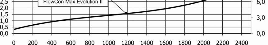
21 Flow rate [US gpm] Pressure [mwc] UniMaxx-Plus-SC-500-AC-V3 Pressure [ft head] Flow rate [l/h]
 Vented Solar Fluid Type % Mix Antifreeze Checked Up To O F Serial Numbers Flow Rate GPM Station Pump Model Controller Pump Stage (I, II, III) Software Ver.")
22 10. Commissioning Log System Operator Installation Site Collector Model (qty) Collector Surface Area ft 2 Piping Ø = in L = ft Ventilation (Collector Field) Manual Bleeder Auto Bleeder No Vented Airstop (Station) Vented Solar Fluid Type % Mix Antifreeze Checked Up To O F Serial Numbers Flow Rate GPM Station Pump Model Controller Pump Stage (I, II, III) Software Ver. System Pressure Expansion Tank Model Initial Pressure psi psi Flow Rate Reducing Position Installation Company Date, Signature
23 5098 NY 206 Bainbridge NY fax
Installation and Commissioning Manual Solar Stations FlowCon FA Evolution II
 PAW NA Limited Partnership 45 Davis Street, Webster, MA 01570 Tel.: +1-508-943-4240, Fax: +1-508-943-4141 Email: info@paw.eu, Web: www.paw.eu Installation and Commissioning Manual Solar Stations FlowCon
Installation and commissioning instructions 255 series and 256 series
 Installation and commissioning instructions 255 series and 256 series Table of contents 1 General information... 3 1.1 About these instructions... 3 1.2 About this product... 3 1.3 Appropriate usage...
AC1810 / AC1810-A TECHNICAL SPECIFICATIONS. Operating Pressure psi ( kgs/cm²) [AC1810] Displacement. Net Weight
![AC1810 / AC1810-A TECHNICAL SPECIFICATIONS. Operating Pressure psi ( kgs/cm²) [AC1810] Displacement. Net Weight](/thumbs/83/88369739.jpg "AC1810 / AC1810-A TECHNICAL SPECIFICATIONS. Operating Pressure psi ( kgs/cm²) [AC1810] Displacement. Net Weight") Technical Specifications Operating Instructions Maintenance Information Troubleshooting Guide Parts Diagrams AC1810 / AC1810-A THE EVOLUTION OF PERFECTION CAUTION: Before attempting to use or service this
Technical Specifications Operating Instructions Maintenance Information Troubleshooting Guide Parts Diagrams AC1810 / AC1810-A THE EVOLUTION OF PERFECTION CAUTION: Before attempting to use or service this
CARTRIDGE FILTERS. Models: CF50, CF75, CF100, CF150,
 CARTRIDGE FILTERS Models: CF50, CF75, CF00, CF50, The installation of this product should be carried out by a qualified pool technician, following the installation instructions provided in this manual.
Budget Range Operators Handbook
 Budget Range Operators Handbook BAMBI AIR COMPRESSORS LTD 152 Thimble Mill Lane Heartlands Birmingham B7 5HT United Kingdom Tel: 0121 322 2299 Fax: 0121 322 2297 Email: sales@bambi-air.co.uk www.bambi-air.co.uk
FlowSol B / B HE * * Manual for the specialised craftsman. Installation Operation Commissioning
 FlowSol B / B HE Manual for the specialised craftsman Installation Operation Commissioning *80060* 80060 Thank you for buying this RESOL product. Please read this manual carefully to get the best performance
PRAHER PLC-MP AQUASTAR MANAUL 2009
 PRAHER PLC-MP AQUASTAR MANAUL 2009 1. Copyrights This Operating Manual contains copyright-protected information. All rights reserved to Praher Kunststofftechnik GmbH. This Operating Manual is designed
Siphon vessel / Priming aid
 Manufacturer: sera GmbH sera-straße 1 34376 Immenhausen Germany Tel.: +49 5673 999-00 Fax: +49 5673 999-01 info@sera-web.com Keep the operating manual for future use! Record the exact type and serial number
ATD LB PRESSURE BLASTER INSTRUCTION MANUAL
 ATD-8402 90LB PRESSURE BLASTER INSTRUCTION MANUAL SAVE THESE INSTRUCTIONS SAFETY INSTRUCTIONS FOR SANDBLASTER 1. Before opening the tank release the air pressure on the sand tank. To do this, turn off
accidents which arise due to non-observance of these instructions and the safety information herein.
 3 GALLON PANCAKE COMPRESSOR Model: 50959 CALIFORNIA PROPOSITION 65 WARNING: You can create dust when you cut, sand, drill or grind materials such as wood, paint, metal, concrete, cement, or other masonry.
OPERATION MANUAL NTF-15
 OPERATION MANUAL NTF-15 Nitrogen Tire Filling Valve Stem Caps (Qty=200) Order P/N 436075 RTI Technologies, Inc 10 Innovation Drive York, PA 17402 800-468-2321 www.rtitech.com 035-81235-00 (Rev B) TABLE
Modular valve block. Operating manual Series MVB 100/200. Version BA EN Print-No TR MA DE Rev001
 Modular valve block Operating manual Series MVB 100/200 Version BA-2016.04.20 EN Print-No. 300 627 TR MA DE Rev001 ASV Stübbe GmbH & Co. KG Hollwieser Straße 5 32602 Vlotho Germany Phone: +49 (0) 5733-799-0
Wafer Check Valve. Contents. User s Manual. (1) Be sure to read the following description of our product warranty 1
 Be sure to read the following description of our product warranty 1") Serial No. H-V066-E-3 Wafer Check Valve User s Manual Contents (1) Be sure to read the following description of our product warranty 1 (2) General operating instructions 2 (3) General instructions for
Serial No. H-V066-E-3 Wafer Check Valve User s Manual Contents (1) Be sure to read the following description of our product warranty 1 (2) General operating instructions 2 (3) General instructions for
TECHNICAL DATA MAINTENANCE AIR COMPRESSOR MODEL G-1
 Dry 131h 1. DESCRIPTION The Viking Model G-1 Maintenance Air Compressor is an electric motor-driven, aircooled, single-stage, oil-less compressor. The unit is equipped with a check valve and provides a
Model PSI Compressor with 3-Gallon Air Tank 12VDC
 Model 6350 150 PSI Compressor with 3-Gallon Air Tank 12VDC IMPORTANT: It is essential that you and any other operator of this product read and understandd the contents of this manual before installing
Safety and operating instructions
 Safety and operating instructions Oil flow dividers 5, 8 www.cp.com 2 Contents Contents Introduction....................................................................... 5 About the Safety and operating
Flowmeter. Original operating manual DFM
 Flowmeter Original operating manual Series DFM 165 350 Version BA-2016.08.09 EN Print-No. 300 458 TR MA DE Rev002 ASV Stübbe GmbH & Co. KG Hollwieser Straße 5 32602 Vlotho Germany Phone: +49 (0) 5733-799-0
E 094 E 103 E 143 Tank top mounting Connection up to G1 / -16 SAE Nominal flow rate up to 135 l/min / 35.7 gpm
 Return Filters E 9 E E Tank top mounting Connection up to G / -6 SAE Nominal flow rate up to 5 l/min / 5.7 gpm Description Application In the return line circuits of hydraulic systems. Performance features
AIR-OPERATED DOUBLE DIAPHRAGM PUMP USER S MANUAL
 00, 0, 000 00, 000, 00 A. TECHNICAL INFORMATION Model 00 Inlet/Outlet " Air Inlet /" 0 / 000 /" /" 00 /" /" 000 /" /" 00 /" /" Flow Rate GPM/ 0LPM GPM/ 0LPM GPM/ LPM GPM/ LPM GPM/ 0LPM GPM/ 0LPM Maximum
AIR COMPRESSOR. Failure to follow all instructions as listed below may result in electrical shock, fire, and/or serious personal injury.
 2 GALLON AIR COMPRESSOR Model: 7517 DO NOT RETURN TO STORE. Please CALL 800-348-5004 for parts and service. CALIFORNIA PROPOSITION 65 WARNING: You can create dust when you cut, sand, drill or grind materials
HERZ-Motorised flow controler
 HERZ-Motorised flow controler Control and regulating valve Data sheet 46, Issue 214 Dimensions in mm 4 close dimension 9,35 M DN G H1 H2 H2 + Actuator B1 B2 1 2 M 1 46 11 15 3/4 G 66 59 73 134 49 63 48
ACCUMULATOR OPERATING & MAINTENANCE INSTRUCTIONS
 ACCUMULATOR OPERATING & MAINTENANCE INSTRUCTIONS READ ALL INSTRUCTIONS PRIOR TO INSTALLATION AND OPERATION TO AVOID POSSIBLE INJURY Warning: Always consider any accumulator to contain pressure until proven
AIR COMPRESSOR OPERATING INSTRUCTION AND PARTS LIST
 AIR COMPRESSOR OPERATING INSTRUCTION AND PARTS LIST OIL-LESS TYPE IMPORTANT: PLEASE READ CAREFULLY BEFORE STARTING OPERATIONS. THE CONTENTS ARE FOR GENERAL INFORMATION OF ALL THE SIMILAR MODELS. Record
accidents which arise due to non-observance of these instructions and the safety information herein. SPECIFICATIONS
 18 GAUGE 2 INCH BRAD NAILER Model: 7555 CALIFORNIA PROPOSITION 65 WARNING: You can create dust when you cut, sand, drill or grind materials such as wood, paint, metal, concrete, cement, or other masonry.
Experiment Instructions. Circulating Pumps Training Panel
 Experiment Instructions Circulating Pumps Training Panel Experiment Instructions This manual must be kept by the unit. Before operating the unit: - Read this manual. - All participants must be instructed
HAYWARD FLOW CONTROL Series PBV Back Pressure Valve and Series RPV Pressure Relief Valve INSTALLATION, OPERATION, AND MAINTENANCE INSTRUCTIONS
 HAYWARD FLOW CONTROL Series PBV Back Pressure Valve and Series RPV Pressure Relief Valve INSTALLATION, OPERATION, AND MAINTENANCE INSTRUCTIONS Page 1 of 20 Page 2 of 20 TABLE OF CONTENTS Safety Warnings
SPECIFICATIONS Type: Twin stack, single phase Tank: 4 gallon Air Output: PSI; PSI Max PSI: 125 PSI HP: 1.
 2 GALLON TWIN STACK AIR COMPRESSOR Model: 9526 DO NOT RETURN TO STORE. Please CALL 800-348-5004 for parts and service. CALIFORNIA PROPOSITION 65 WARNING: You can create dust when you cut, sand, drill or
accidents which arise due to non-observance of these instructions and the safety information herein. SPECIFICATIONS
 18 GAUGE 1-1/4 INCH BRAD NAILER Model: 7611 CALIFORNIA PROPOSITION 65 WARNING: You can create dust when you cut, sand, drill or grind materials such as wood, paint, metal, concrete, cement, or other masonry.
Jacuzzi. J-CQ420 Cartridge Filter Installation and Operating Instructions
 Jacuzzi J-CQ420 Cartridge Filter Installation and Operating Instructions IMPORTANT SAFETY PRECAUTIONS ATTENTION INSTALLER: This guide contains important information about the installation, operation and
INSTALLATION INSTRUCTIONS Non-Pressurized Tank. Non-Pressurized Tank Part Number: AFCG1PT
 INSTALLATION INSTRUCTIONS Non-Pressurized Tank Non-Pressurized Tank Part Number: AFCG1PT Table of Contents General Desc on 2 Ins n 3 Flushing and Purging 5 Start-up 7 Adding or Checking Fluid 8 Replacing
User Instruction Manual
 User Instruction Manual 4500 psi Air Compressor Ver 2, 1.18 Contents Parts Included...3 Assembly Instructions...3-5 Operation Instructions...6-7 Oil Change Intervals...8 Air Filter Replacement...9 Setting
PRESSURE TEST PUMP OPERATING & MAINTENANCE INSTRUCTIONS. Model No: PTP100. Part No: GC01/09
 PRESSURE TEST PUMP Model No: PTP00 Part No: 06020 OPERATING & MAINTENANCE INSTRUCTIONS GC0/09 INTRODUCTION Thank you for purchasing this CLARKE Pressure Testing Pump. Before attempting to use the product,
OPERATION MANUAL NTF-60 Plus
 OPERATION MANUAL NTF-60 Plus Nitrogen Tire Filling Valve Stem Caps (Qty=200) Order P/N 436075 RTI Technologies, Inc 10 Innovation Drive York, PA 17402 800-468-2321 www.rtitech.com 035-81264-00 (Rev A)
SILENTAIRE TECHNOLOGY
 SILENTAIRE TECHNOLOGY 8614 Veterans Memorial. Houston, Texas 77088 832/327-7452 800/972-7668 Fax: 832/327-0668 E-mail: silentaire@silentaire.com Thank you and congratulations on the purchase of your OILLESS
Bermad Pressure Reducing. Model: 42T
 Bermad Pressure Reducing Pilot Operated Pressure Control Valve Model: 42T Installation Operation Maintenance Manual (IOM) REV. 27.7.17 Page 1 of 12 Safety First BERMAD believes that the safety of personnel
FOR INSTALLING CO 2 BLENDER KIT (P/N IN BEER SYSTEM
 IMI CORNELIUS INC One Cornelius Place Anoka, MN 55303-623 Telephone (800) 238-3600 Facsimile (612) 22-326 INSTALLATION INSTRUCTIONS FOR INSTALLING CO 2 BLENDER KIT (P/N 111612000 IN BEER SYSTEM SECONDARY
AMP Oil Free Manual AMP 50-8-TC AMP 50-6-D AMP General User and Maintenance Instructions
 AMP Oil Free Manual AMP 50-8-TC AMP 50-6-D AMP 50-24 General User and Maintenance Instructions Silentaire Technology 8614 Veterans Memorial Dr. Houston, TX 77088 800-972-7668 Fax 832-327-0669 www.silentaire.com
1 DRIVE INDUSTRIAL IMPACT WRENCH
 1 DRIVE INDUSTRIAL IMPACT WRENCH 92622 ASSEMBLY AND OPERATING INSTRUCTIONS 3491 Mission Oaks Blvd., Camarillo, CA 93011 Visit our Web site at http://www.harborfreight.com Copyright 2004 by Harbor Freight
Pressure Independent Control Series
 Document No. 155-522 Pressure Independent Control Series Two-Way Cast Iron Flanged Bodies, ANSI 125 and 250 Description Siemens Pressure Independent Control Valves integrate three functions into a single
3 GALLON, OILLESS PANCAKE COMPRESSOR INSTRUCTIONS. Item #31289
 3 GALLON, OILLESS PANCAKE COMPRESSOR INSTRUCTIONS Item #31289 The EASTWOOD 3 GALLON, OILLESS PANCAKE COMPRESSOR, with an Integral Air Regulator, efficiently supplies all compressed air requirements for
SILENTAIRE TECHNOLOGY
 SILENTAIRE TECHNOLOGY General User and Maintenance Instructions Thank you and congratulations on the purchase of your PANTHER, the leader in the industry of portable air compressors. The PANTHER is built
ENERGY BLADE 3K4. Energy Blade Installation Instructions
 ENERGY BLADE 3K4 Energy Blade Installation Instructions 1 Contents General information 2 Scope of these instructions 2 Product information 2 Designated use 3 Warranty 3 Safety instructions 4 Assembly and
2-port seat valves PN25 with externally threaded connections
 4 379 2-port seat valves PN25 with externally threaded connections VVG55.. Valve body bronze CC491K (Rg5) DN 15...25 (½...1 ") kvs 0.25...6.3 m3/h Stroke 5.5 mm Sets of ALG.. with threaded and ALS.. with
3:1 High Ratio Oil Pump W. Extn. Kit
 3:1 High Ratio Oil Pump W. Extn. Kit OWNER S MANUAL WARNING: Read carefully and understand all INSTRUCTIONS before operating. Failure to follow the safety rules and other basic safety precautions may result
Discharge Relief Valve Operation & Maint.
 Relief Valve Operation & Maint. CZ Series Centrifugal Fire Relief svalve Operation and Maintenance Instructions 1410 Operation and Maintenance Form No. F-1031 Section 2302.6 2111 Issue Date 04/90 11/95
Portable Oil Lube Air Compressors
 Portable Oil Lube Air Compressors 8003631 8003632 0410149 8018968 8018940 Owner s Manual Read and understand operating instructions before use Safety definitions The information listed below should be
400C & 450C DUAL PERFORMANCE VALUE PACKS
 (Chrome) PART NO. 40013 (Silver) PART NO. 45012 (Chrome) PART NO. 45013 IMPORTANT: It is essential that you and any other operator of this product read and understand the contents of this manual before
BOSS PULISCI PROVA IMPIANTI MEDIA
 BOSS PULISCI PROVA IMPIANTI MEDIA Pump for power flushing operations and removal of impurities, suitable for hydraulic, solar, floor systems and for cooling circuits of medium size. Suitable for buildings,
FILTER REGULATORS MODEL NO: CAT155 & CAT156 FITTING & MAINTENANCE INSTRUCTIONS PART NO: & ORIGINAL INSTRUCTIONS
 FILTER REGULATORS MODEL NO: CAT155 & CAT156 PART NO: 3120169 & 3120170 FITTING & MAINTENANCE INSTRUCTIONS ORIGINAL INSTRUCTIONS GC0117 INTRODUCTION Thank you for purchasing this CLARKE Filter/Regulator.
97C COMPRESSOR KIT 12V PART NO C COMPRESSOR KIT 24V PART NO C COMPRESSOR KIT PART NO
 97C COMPRESSOR KIT 12V PART NO. 00097 97C COMPRESSOR KIT 24V PART NO. 02497 98C COMPRESSOR KIT PART NO. 00098 97C 98C IMPORTANT: It is essential that you and any other operator of this product read and
Vessel Installation and Operating Manual
 For In-ground and Aboveground Pools Vessel Installation and Operating Manual Important Safety Information Please read this manual prior to installation. Nature 2 Express is designed to sanitize in-ground
IMPORTANT SAFETY INSTRUCTIONS
 IMPORTANT SAFETY INSTRUCTIONS CAUTION - To reduce risk of electrical shock: - Do not disassemble. Do not attempt repairs or modifications. Refer to qualified service agencies for all service and repairs.
553 Series.
 38467.03 www.caleffi.com Pre-adjustable filling units Copyright 01 Caleffi 3 Series Function The automatic filling valve is a device consisting of a pressure reducing valve with compensating seat, visual
RS(H)10,15 USER MANUAL. Read the complete manual before installing and using the regulator.
10,15 USER MANUAL. Read the complete manual before installing and using the regulator.") RS(H)10,15 USER MANUAL Read the complete manual before installing and using the regulator. WARNING INCORRECT OR IMPROPER USE OF THIS PRODUCT CAN CAUSE SERIOUS PERSONAL INJURY AND PROPERTY DAMAGE. Due to
RS(H)10,15 USER MANUAL Read the complete manual before installing and using the regulator. WARNING INCORRECT OR IMPROPER USE OF THIS PRODUCT CAN CAUSE SERIOUS PERSONAL INJURY AND PROPERTY DAMAGE. Due to
Model: 43T. Bermad Pressure Relief Valve
 Model: 43T Bermad Pressure Relief Valve Installation Operation Maintenance Manual () Rev.C1_01.08.17 Page 1 of 10 Safety First BERMAD believes that the safety of personnel working with and around our equipment
Design DSA Steam-Atomized Desuperheater
 Instruction Manual DSA Desuperheater Design DSA Steam-Atomized Desuperheater Contents Introduction............................... 1 Scope of Manual......................... 1 Description..............................
130400A 1/2 NPT Female A 3/4 NPT Female A 1 NPT Female A 1 1/4 NPT Female A 1 1/2 NPT Female A 2 NPT Female
 88.0A www.caleffi.com Venturi Style Balancing Valve Copyright 0 Caleffi 0 Series Function Product Range Balancing valves are hydraulic devices that can precisely control the flow rate of the fluid that
TD45 Thermodynamic Steam Trap Installation and Maintenance Instructions
 0685255/1 IM-P068-47 ST Issue 1 TD45 Thermodynamic Steam Trap Installation and Maintenance Instructions 1 General safety information 2 General product information 3 Installation 4 Commissioning 5 Operation
Instruction presentation Special valves
 Instruction presentation Special valves 1 Special Valves 2 Special Valves Index of contents 1. Overview special valves 2. Description Gauge Guard 3. Description Water Jet Pumps 4. Description Venting and
Pressure Limiting Valve SPVF Operating Instructions
 Pressure Limiting Valve SPVF Operating Instructions Industriehydraulik Contents Safety 1 Identification of safety instructions 1 General Safety Instructions 1 Address off Manufacturer 1 The Documentation
WW-720. Pressure Reducing Control Valve
 WW-720 Pressure Reducing Control Valve (Size Ranges: 2-4 and 6-14 ) Installation Operation & Maintenance Page 1 of 6 1. DESCRIPTION The Model 720 Pressure Reducing is an automatic control valve (powered
air/hydraulic nut riveter heavy-duty vacuum system
 instructions for air/hydraulic nut riveter heavy-duty vacuum system model no: SA317 Thank you for purchasing a Sealey product. Manufactured to a high standard, this product will, if used according to these
Assembly-, installation- and maintenance instruction manual for bladder accumulators IBV / EBV , top reparable
 Page 1 von 8 Assembly-, installation- and maintenance instruction manual for bladder accumulators IBV / EBV 100-575, top reparable Content Seite 0 Legend 2 1 Overview 2 2 Accumulator assembly and installation
Armatures for analytical probes
 Armatures for analytical probes For many different types of installations and applications Large range of probe holders General purpose, water treatment, food & beverage, pharmaceutical applications Type
Assembly Drawing: W-311B-A01, or as applicable Parts List: W-311B-A01-1, or as applicable Special Tools: , , &
 REDQ Regulators Model 411B Barstock Design Powreactor Dome Regulator OPERATION AND MAINTENANCE Contents Scope..............................1 Installation..........................1 General Description....................1
WW-720. Pressure Reducing Control Valve
 WW-720 Pressure Reducing Control Valve (Size Ranges: 2-4 and 6-14 ) Installation Operation & Maintenance Page 1 of 6 1. DESCRIPTION The Model 720 Pressure Reducing is an automatic control valve (powered
GENO -Flushing Compressor Product Data Sheet F 02
 GENO -flushing compressor 1988 K Fig. 1: GENO -flushing compressor 1988 K Designated application is suitable for the following fields of application: Flushing of pipes with water/air mix prior to the start-up
INTENDED USE TECHNICAL SPECIFICATIONS
 1/2IN. HEAVY-DUTY AIR IMPACT WRENCH OWNER S MANUAL WARNING: Read carefully and understand all INSTRUCTIONS before operating. Failure to follow the safety rules and other basic safety precautions may result
VB85/ Pressure regulating valve (Unloader)
") Ultimo aggiornamento: 20/09/12 VB85/160 280 Pressure regulating valve (Unloader) At gun closure, the waterflow is discharged in bypass reducing the pressure in the system upstream of the valve. Technical
Ultimo aggiornamento: 20/09/12 VB85/160 280 Pressure regulating valve (Unloader) At gun closure, the waterflow is discharged in bypass reducing the pressure in the system upstream of the valve. Technical
310 SERIES TILT-TO-LOAD ROTATOR. The Specialist In Drum Handling Equipment
 OPERATOR S MANUAL FOR MORSE TILT-TO-LOAD DRUM ROTATOR SAFETY INFORMATION: While Morse Manufacturing Co. drum handling equipment is engineered for safety and efficiency, a high degree of responsibility
Installation, Operation and Maintenance Instructions for Mild Steel Buffer Vessel
 OM006 Installation, Operation and Maintenance Instructions for Mild Steel Buffer Vessel The operating and maintenance instructions contained within this package are for standard mild steel buffer vessels
CONGRATULATIONS ON YOUR PURCHASE OF YOUR THUNDER COMPRESSOR For your personal safety please read, understand and follow the information provided in
 CONGRATULATIONS ON YOUR PURCHASE OF YOUR THUNDER COMPRESSOR For your personal safety please read, understand and follow the information provided in this instruction manual. 1 CONTENTS 3. Safety Precautions
100C Air Compressor Kit
 10010 100C Air Compressor (standard mounting bracket, CE Spec) 10014 100C Air Compressor (no leader hose or check valve, CE Spec) 10016 100C Air Compressor (with Omega Bracket, CE Spec) IMPORTANT: It is
Flexvent floatvents: reliable and easy to mount
 floatvents: reliable and easy to mount The floatvents /80, /80 - /80, /20 and /40 are supplied together with a shut-off valve to facilitate mounting and removal. When the floatvent is unscrewed from the
Pressure Dump Valve Service Kit for Series 3000 Units
 Instruction Sheet Pressure Dump Valve Service Kit for Series 000 Units. Overview The Nordson pressure dump valve is used to relieve hydraulic pressure instantly in Series 00, 400, 500, and 700 applicator
Advanced Fluid Handling Cart Owner s Manual
 Advanced Fluid Handling Cart IMPORTANT Please read this carefully and thoroughly before installing and operating your Advanced Fluid Handling Cart. Please retain this owner s manual for future reference
E 084 Tank top mounting Connection up to G1 / -16 SAE Nominal flow rate up to 80 l/min / 21.1 gpm
 Return-Suction Filters E 08 Tank top mounting Connection up to G / -6 SE Nominal flow rate up to 80 l/min /. gpm Description pplication For operation in units with hydrostatic drives, when the return flow
Installation and Operating Manual
 Safety Instructions Important Information Please read prior to installation ATTENTION! ELECTRICAL HAZARD FOR INGROUND POOLS AND ABOVEGROUND POOLS Installation and Operating Manual IMPORTANT Pool Owner,
VERTICAL AIR COMPRESSORS
 VERTICAL AIR COMPRESSORS MODEL NO: VE15C150, VE18C150, VE25C150 PART NO: 2226010, 2226020, 2226025 OPERATION & MAINTENANCE INSTRUCTIONS LS0715 INTRODUCTION Thank you for purchasing this CLARKE Vertical
420C AIR COMPRESSOR KIT PART NO C AIR COMPRESSOR KIT PART NO
 420C AIR COMPRESSOR KIT PART NO. 42042 460C AIR COMPRESSOR KIT PART NO. 46043 420C 460C IMPORTANT: It is essential that you and any other operator of this product read and understand the contents of this
Installation, Operation and Maintenance Instructions for Electronically Controlled Pressurisation Units
 Installation, Operation and Maintenance Instructions for Electronically Controlled Pressurisation Units Models: EPS Single Pump EPT Twin Pump EPS-HP EPT-HP Single Pump High Pressure Twin Pump High Pressure
Installation, Operation and Maintenance Manual for Back Pressure Regulator
 Installation, Operation and Maintenance Manual for Back Pressure Regulator Model 8860 2009 Groth Corporation IOM-8860 Rev. B 12541 Ref. ID: 95565 Page 2 of 13 Table of Contents I. INTRODUCTION 3 II. DESIGN
INSTALLATION INSTRUCTIONS MANUAL ON/OFF SAFETY VALVE/PILOT KIT MODEL GA9050A-1 (F0235)
") P/N 126905-01 Rev. B 11/2016 INSTALLATION INSTRUCTIONS MANUAL ON/OFF SAFETY VALVE/PILOT KIT MODEL GA9050A-1 (F0235) For All Single, Dual and Triple Burner Natural and Propane/LP Gas Logs P126905-01 For
P/N 126905-01 Rev. B 11/2016 INSTALLATION INSTRUCTIONS MANUAL ON/OFF SAFETY VALVE/PILOT KIT MODEL GA9050A-1 (F0235) For All Single, Dual and Triple Burner Natural and Propane/LP Gas Logs P126905-01 For
200 PSI HIGH-FLOW AIR SOURCE KIT
 200 PSI HIGH-FLOW AIR SOURCE KIT 50% Duty Compressor on 2.0 Gallon Air Tank PART NO. 20008 IMPORTANT: It is essential that you and any other operator of this product read and understand the contents of
Composite Pistol-Type Air Needle Scaler OWNER S MANUAL
 Composite Pistol-Type Air Needle Scaler OWNER S MANUAL WARNING: Read carefully and understand all INSTRUCTIONS before operating. Failure to follow the safety rules and other basic safety precautions may
OWNER S TECHNICAL MANUAL
 EL SERIES OWNER S TECHNICAL MANUAL DP7002 1 Air Operated Diaphragm Pump Description The DP7002 1 air operated diaphragm pump is the ideal device for the pumping, transfer and dispensing of chemical liquids,
Product Sheet Spraymist Unit
 Product Sheet Spraymist Unit DESCRIPTION The Spraymist unit is perfectly adapted for use with differents liquids for applications as metalcutting, drilling, grinding, cooling or wetting processes and chain
SAFETY MANUAL FOR FLAMMABLE PRODUCT TRANSFER
 SAFETY MANUAL FOR FLAMMABLE PRODUCT TRANSFER SUPPLIMENT TO eom IMPORTANT READ THIS MANUAL BEFORE PRODUCT INSTALLATION, OPERATION, INSPECTION & MAINTENANCE Tougher and more rigid guidelines are being established
Pressure Dump Valve Service Kit for Series 2300 Units
 Instruction Sheet Pressure Dump Valve Service Kit for Series 00 Units. Overview The Nordson pressure dump valve is used to relieve hydraulic pressure instantly in Series 00 applicator tanks when the unit
Installation and Maintenance Manual. ECO Filtration Unit with 6-way-Top-Mount-Valve. Art. Nr
 Installation and Maintenance Manual ECO Filtration Unit with 6-way-Top-Mount-Valve Art. Nr. 300100 300101 300102 Important Details: - Using of this filtration unit for swimming pools and its guard band
250C-IG COMPRESSOR KIT 12V PART NO C-IG COMPRESSOR KIT 24V PART NO
 250C-IG COMPRESSOR KIT 12V PART NO. 25050 250C-IG COMPRESSOR KIT 24V PART NO. 25058 IMPORTANT: It is essential that you and any other operator of this product read and understand the contents of this manual
VERTICAL AIR COMPRESSORS
 VERTICAL AIR COMPRESSORS MODEL NO: VE11C150, VE15C150, VE18C150 PART NO: 2226005, 2226000, 2226015 OPERATION & MAINTENANCE INSTRUCTIONS LS0615 INTRODUCTION Thank you for purchasing this CLARKE Vertical
G7S Hand Pump Owner s Manual
 G7S Hand Pump Owner s Manual Copyright Air Venturi 2018 Version 4-18 Specifications 24.80 inches long closed 43.31 inches long extended 4500 psi/310 bar max pressure Features Integral manometer (pressure
Tank Blanketing Pressure Regulators RHPS Series
 www.swagelok.com Tank Blanketing Pressure Regulators RHPS Series Types: pressure reducing and vapor recovery 16L stainless steel construction 1/2, 1, and 2 in. end connections Working pressures up to 22
Operating and maintenance manual Filter and reducing station Series / 1.0
 Operating and maintenance manual Filter and reducing station Series 961 04.2017 / 1.0 Original instructions ARCA Regler GmbH. All rights reserved. Cover picture background: Freepik.com ARCA Regler GmbH
6900 Maintenance Instruction System Flush
 Equipment Required FA74005 Damper Drain Tube FA16005 Cover Removal Tool FA900005 Beaker 0.25 Litre FA900003 Solvent Cleaning Bottle FA940021 Syringe Polypropylene 50 ml as required FA999045 Gloves Latex
USM21 Sealed Bimetallic Steam Trap for use with Pipeline Connectors Installation and Maintenance Instructions
 6250250/1 IM-P625-03 ST Issue 1 USM21 Sealed Bimetallic Steam Trap for use with Pipeline Connectors Installation and Maintenance Instructions 1. General safety information 2. General product information
VIESMANN. Service instructions VITOSOL 200-T, 300-T. for contractors. Vitosol 200-T, 300-T. For applicability, see the last page
 Service instructions for contractors VIESMANN Vitosol 200-T, 300-T For applicability, see the last page VITOSOL 200-T, 300-T 12/2008 Please keep safe. Safety instructions Safety instructions Please follow
PRS(TC)4,8 USER MANUAL. Read the complete manual before installing and using the regulator.
4,8 USER MANUAL. Read the complete manual before installing and using the regulator.") PRS(TC)4,8 USER MANUAL Read the complete manual before installing and using the regulator. WARNING INCORRECT OR IMPROPER USE OF THIS PRODUCT CAN CAUSE SERIOUS PERSONAL INJURY AND PROPERTY DAMAGE. Due to
PRS(TC)4,8 USER MANUAL Read the complete manual before installing and using the regulator. WARNING INCORRECT OR IMPROPER USE OF THIS PRODUCT CAN CAUSE SERIOUS PERSONAL INJURY AND PROPERTY DAMAGE. Due to
Pneumatic proportional controller Types M Types FM Function tested for use of the float in Ex-zone 0
 Operating Manual LTIA5E Pneumatic proportional controller Types M Types FM Function tested for use of the float in Ex-zone 0 Contents 1. Safety Instructions 2. Conformity to standards 3. Technical data