FRONTIER II JUMP STAND W/ JIG
|
|
|
- Bethanie Tate
- 5 years ago
- Views:
Transcription


1 FRONTIER II JUMP STAND W/ JIG ASSEMBLY AND INSTALLATION INSTRUCTIONS **PROFESSIONAL INSTALLATION RECOMMENDED** POOL WATER ENVELOPE DIMENSIONS MUST MEET OR EXCEED ANSI/APSP/ICC STANDARDS FOR THIS BOARD/STAND. USE ONLY WITH A COMPATIBLE S.R. SMITH DIVING BOARD/STAND. S.R. SMITH DIVING BOARDS AND RELATED EQUIPMENT ARE FOR IN-GROUND POOLS ONLY. DO NOT USE WITH OTHER POOLS, DOCKS, ETC. USE WITH AN IMPROPERLY-SIZED POOL, INCOMPATIBLE STAND/BOARD, OR IMPROPER INSTALLATION MAY RESULT IN DEATH OR SERIOUS INJURY. ATTENTION! THESE INSTRUCTIONS MUST REMAIN WITH PLATFORM OWNER MAR16

2 Assembly and Installation Instructions for S.R. Smith s 1/2 METER FRONTIER II JUMP STAND W/ JIG STEEL STAND COMPLETE: 6 Board 8 Board TABLE OF CONTENTS FRONTIER II JUMP STAND MOUNTING KIT... 2 INSTALLATION INSTRUCTIONS... 2 ARTICLE 5 POOL DIMENSIONS AND TOLERANCES EXTRACTED FROM THE ANSI/APSP/ICC AMERICAN NATIONAL STANDARD FOR RESIDENTIAL INGROUND SWIMMING POOLS... B REGISTER YOUR S.R. SMITH PRODUCT AT Visit srsmith.com for information on the complete line of S.R.Smith pool products. SRS AUSTRALIA, PTY LTD 12 Enterprise St Richlands QLD 4077 Australia Phone Fax S.R. SMITH, LLC CORPORATE HEADQUARTERS P.O. Box S.W. Berg Parkway Canby, Oregon USA Phone (503) Fax (503)
3 FRONTIER II JUMP STAND MOUNTING KIT FIGURE A TIGHTENING SCHEDULE 1. SECURE BOARD TO STAND WITH MOUNTING HEX NUTS FIBERGLASS FT-LBS 2. SECURE STAND TO JIG WITH ANCHOR HEX NUTS FT-LBS. FIGURE B FRONTIER II MOUNTING BOLT KIT ( SS) 1. STEP BOLT HEAD CAP WHITE RUBBER (3 EA) 2. 1/2 x 3 LG. STEP BOLT S/S (3 EA) 3. 1/2 x 1-1/2 ROUND NYLON WASHER (3 EA) 4. 1/2 x 1-3/8 FLAT WASHER S/S (3 EA) 5. 1/2 LOCK WASHER S/S (3 EA.) 6. 1/2 HEX NUT S/S (3 EA.) 7. 1/2 WHITE PLASTIC NUT CAP (3 EA.) FRONTIER II SPRING ANCHOR BOLT KIT ( SS) 8. 5/8 X 1-3/4 NYLON PROTECTIVE WASHER (3 EA.) 9. 5/8 X 1-3/4 FLAT WASHER S/S (3 EA.) 10. 5/8 LOCK WASHER S/S (3 EA.) 11. 5/8 HEX NUT S/S (3 EA.) 12. 5/8 WHITE RUBBER NUT CAP (3 EA.) 3
4 INSTALLATION INSTRUCTIONS TABLE 1 FRONTIER II JUMP STAND INSTALLATION CHART Refer to FIGURE A Model Frontier II Diving Board Length Distance For Setting Front Bolt of Jig From Water s Edge S Pool Type (ANSI/APSP/ICC ) I or II III III IV IV V Min. Overhang ± 3 (76mm) WA* Max. Height of Board Above Water HOW IMPORTANT: The distance for setting the front bolt of the jig S from the water s edge is valid only if the minimum water depth is maintained at the tip of the board noted at point A in ANSI/APSP/ICC , Figure 3 and Table 1. If minimum water depth is not maintained the distance S must be adjusted accordingly. *WA DIMENSION IS VALID ONLY IN CONJUNCTION WITH MIN. DEPTH AT POINT A (SEE ANSI/APSP/ICC FIGURE 3 AND TABLE 1) FOR POOL TYPE. **When coping is used do not set front bolt of jig closer than 3 (76 mm) from the back edge of coping. BE SURE CONCRETE DECK SURROUNDING ANCHOR JIG COMPLIES WITH MINIMUM DIMENSIONS IN FIGURE A. **Professional installation recommended** **Improper installation voids S.R. Smith s Limited Product Warranty** 1. Verify that the pool water envelope dimensions meet or exceed ANSI/APSP/ICC standards for this board and stand. Excerpts from the applicable ANSI/APSP/ICC standard are attached and more information on safe installation is available at Warning: using the diving board and stand with an improperly-sized pool may result in death or serious injury. 2. Verify that the board is compatible with the S.R. Smith diving board stand. A matrix of compatible products is attached and available at 3. Identify installation site. Board must be placed at deep end of pool on centerline. Set Frontier II three bolt jig in accordance with the Installation Chart above and FIGURE A, with the two RED capped bolts closest to the pool. CAUTION: Before pouring concrete around jig, check the bolt pattern of jig to FIGURE B. It is possible that they have become misaligned through shipping and handling. 4
5 4. Make sure bolts project out of concrete 1-1/2" with ample concrete depth below jig. Refer to FIGURE A for minimum deck thickness, width and length. 5. When finishing deck surface, maintain a LEVEL DECK SURFACE where jig bolts project out so that the stand makes uniform contact with deck. 6. Before mounting stand, chisel away any excess concrete that may have built up around jig bolts and remove the red and yellow bolt caps. 7. Place stand over jig bolts and secure according to FIGURE B. Tighten ANCHOR hex nuts. Tighten all MOUNTING and ANCHOR hex nuts according to the TIGHTENING SCHEDULE in FIGURE A. 8. With Frontier II stand properly secured, select board size according to INSTALLATION CHART above. Take the White Rubber Step Bolt Caps and pullover the heads of the 1/2" x 3" long Step Bolts. When inserting Step Bolts through the board holes, tap with a rubber mallet in order to obtain a snug fit. Secure Frontier II jump board to stand according to FIGURE B and tighten MOUNTING hex nuts. 9. The top surface of the diving board shall be level from side to side. 10. The top surface of the diving board from the deck end to the tip end shall be level or have an upward slope of 5/8 per foot (16 mm: 305mm) maximum. Elevation difference shall not exceed 6 inches (152mm) from the deck end to the tip of the board. There shall be no downward slope towards the water. The slope shall be measured using a level as shown in FIGURE D. NOTICE: S.R. SMITH CANNOT GUARANTEE CUSTOMER S CONCRETE STRENGTH OR THICKNESS IMPORTANT NOTICE: IT IS NECESSARY TO USE AN ANTI-SEIZE COMPOUND ON ALL STAINLESS STEEL HARDWARE. FAILURE TO USE ANTI-SEIZE COMPOUND MAY RESULT IN GALLING AND SEIZING OF THE HARDWARE. ONLY ONE PERSON ON DIVING PLATFORM AT A TIME WITH A MAXIMUM WEIGHT OF 250 LBS (113kg) 5
6 TABLE 2 S.R. SMITH RESIDENTIAL POOL SPECIFICATIONS IMPORTANT: Maximum diving board length, maximum height over water at point A, and minimum cross section dimensions at point A and B shall be in accordance with Table 2 and FIGURE C. Pool Type MAX. DIVING BOARD LENGTH MAX. HEIGHT OVER WATER AT POINT A CROSS SECTIONAL DIMENSIONS AT POINT A CROSS SECTIONAL DIMENSIONS AT POINT B DBL** HOW** F G H J K L M N 0 DIVING EQUIPMENT IS PROHIBITED I 6' (1.83m) DB/ 6 (1.83m) JB 20 (50.8cm) 2'-9" (83.8cm) 5'-0" (1.52m) 4'-0" (1.22m) 7'-2 1/2" (2.20m) 7'-6" (2.29m) 6'-0" (1.83m) 3'-9" (1.14m) 2'-1 1/2" (64.8cm) II 8' (2.44m) DB/ 6 (1.83m) JB 20" (50.8cm) 2'-9" (83.8cm) 3'-10" (1.17m) 4'-2" (1.27m) 7'-2 1/2" (2.20m) 7'-6" (2.29m) 6'-8" (2.03m) 3'-9" (1.14m) 2'-1 1/2" (64.8cm) III 10' (3.05m) DB/ 8 (2.44m) JB 26" (66cm) 2'-9" (83.8cm) 4'-4 3/4" (1.34m) 4'-4 1/2" (1.33m) 7'-5 1/2" (2.27m) 8'-0" (2.44m) 6'-7" (2.01m) 3'-11 1/2" (1.21m) 1'-7 1/2" (49.5cm) IV 10' (3.05m) DB/ 8 (2.44m) JB 30" (76.2cm) 2'-9" (83.8cm) 5'-10 1/2" (1.79m) 3'-10" (1.17m) 7'-8" (2.34m) 8'-6" (2.59m) 8'-3" (2.51m) 5'-7" (1.70m) 2'-7" (78.7cm) V 12' (3.66m) DB/ 8 (2.44m) JB 40" (1m) 2'-9" (83.8cm) 6'-2" (1.88m) 3'-11 1/2" (1.21m) 7'-9 1/2" (2.37m) 9'-0" (2.74m) 8'-2 1/2" (2.50m) NOTES: 1. ** ABBREVIATIONS: DBL = Diving Board Length, DB = Diving Board, JB = Jump Board, HOW = Height Over Water. 2. IMPORTANT: The walls of a Type I Pool, when defining the Maximum Diving Water Envelope shall be plumb. 3. All dimensions are minimum, except where noted as maximum. 4. One half (1/2) the width shown at each point shall be available on each side of the diving equipment centerline. 5. Minimum water depth under tip of diving board (Point A) is important to maintain. 5'-9" (1.75m) 2'-1" (63.5cm) FIGURE C Minimum Cross Sections (Refer to ANSI/APSP/ICC Figure 3 on Page B) FIGURE D TABLE 3 Minimum Headroom Requirements Minimum unobstructed headroom from the top of the manufactured diving equipment is specified below. Minimum Headroom Above Pool Type Diving Surface I 12 feet (3.7 m) II 12 feet (3.7 m) III 13 feet (4 m) IV 13 feet (4 m) V 14 feet (4.3 m) 6
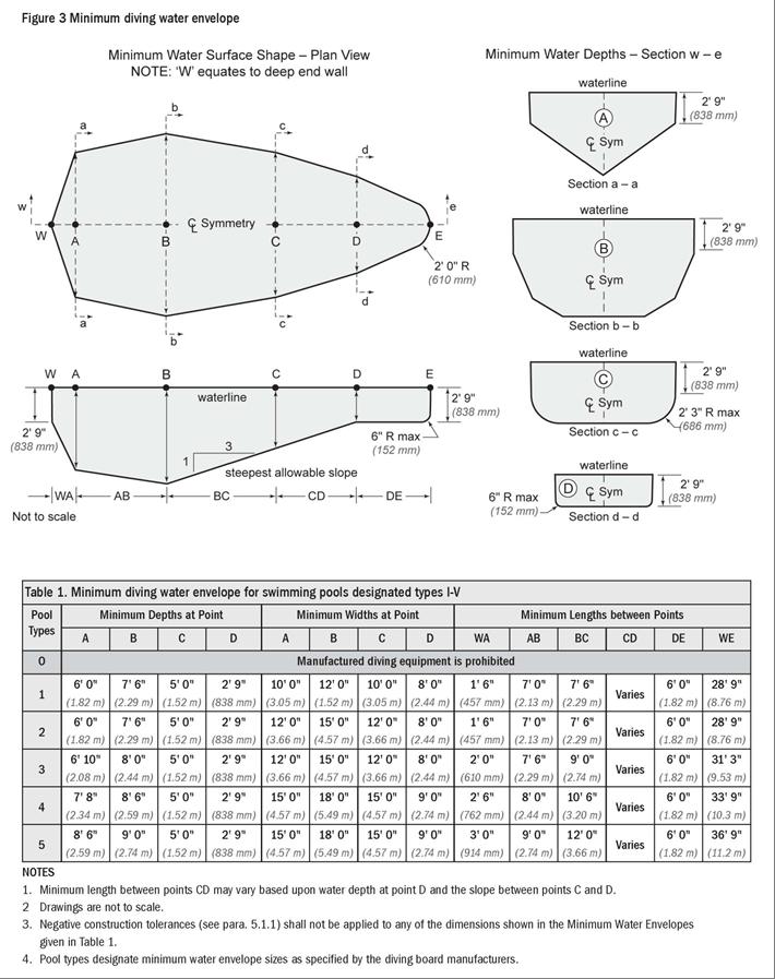
7 ARTICLE 5 POOL DIMENSIONS AND TOLERANCES EXTRACTED FROM THE ANSI/APSP/ICC AMERICAN NATIONAL STANDARD FOR RESIDENTIAL INGROUND SWIMMING POOLS 5 Pool Dimensions and Tolerances 5.1 General requirements. Design dimensions shall comply with the specifications in this standard. The pool shall be constructed to these design dimensions within the tolerances listed in Construction tolerances. There shall be construction tolerances allowed on dimensional designs. The length, width, and depth shall be limited to a tolerance of plus or minus 3 in. (±76 mm). All other dimensions shall be limited to a tolerance of ±2 in. (±51 mm), unless otherwise specified. NOTE: Negative construction tolerances shall not be applied to the shallow area dimensions of the Minimum Diving Envelope given in Table 1, p Perimeter shape. No limits are specified for shapes of pools. Consideration shall be given to circulation and safety to the user. 5.3 Walls Requirements Walls in the shallow area and deep area of the pool shall not slope greater than 11 (5:1 slope ratio) to a transition point of the floor (see Figure 1). The transition to the bottom of the pool between points D and E (see Figure 3, p. 5) shall not be less than 2 ft 3 in. (686 mm) below the waterline As shown in Figure 2, at the depths of (A) and (B), the walls are permitted to continue to join the floor. A
8 B
9 5.4 Offset Ledges Offset ledges shall be a maximum of 8 in. (203 mm) wide Offset ledges located less than 42 in. (1.07 m) below waterline shall be proportionately less than 8 in. (203 mm) wide and fall within 11 from plumb, measured from the top of the waterline (see Figure 4). 5.5 Floor slopes. Floor slopes shall be reasonably uniform and comply with paras through The slope of the floor from the shallow end wall towards the deep area shall not exceed a 1:7 incline to the point of the first slope change, if any (D E) as shown in Figure Changes in slope between shallow and deep areas shall be at a minimum water depth of 2 ft 9 in. (838 mm) and be at least 6 ft (1.83 m) from the shallow end, except as specified in para The slope of the floor shall not exceed a 1:3 incline under the lengths (B D) of the Diving Envelope (see Figure 5). 5.6 Shallow end water depths. Water depth in the shallow area shall be a minimum of 2 ft 9 in. (838 mm), except for those locations specified in para. 6.3 Shallow End Detail for Beach and Sloping Entries. 5.7 Manufactured diving equipment for in-ground swimming pools (diving board/stand combination, manufactured platform, or field fabricated) When manufactured or field fabricated diving equipment is installed, it shall conform to the specifications set forth in paras It shall be located in the deep area of the pool to provide the minimum dimensions as shown in para. 5.8, and shall be installed in accordance with manufacturer s instructions Manufactured or field fabricated diving equipment shall be located directly above Point A. Diving equipment shall not be installed on Type O pools (see Table 1) Maximum elevation of a diving board above the water shall be in accordance with manufacturer s installation instructions. Raised decking may be installed around the diving board up to level with the top of the board Manufactured diving equipment installation and use instructions shall be provided by the diving equipment manufacturer and shall specify the minimum water dimensions required for each diving board and diving stand combination. They shall refer to the diving envelope type of their choice by dimensionally relating their products to Point A on the diving envelopes as shown in Figure 3, Table 1, and paras Diving equipment shall be permanently labeled and affixed to the diving equipment or jump boards and include, but not be limited to the following: manufacturer s diving equipment name and address date of manufacture minimum diving envelope maximum weight limitations Diving equipment shall have slip-resisting tread surfaces. 5.8 Figure 3 diagrams show dimension points referred to in Table Point A: Point A is the point from which all other forward dimensions of width, length, and depth are then established for the Minimum Diving Water Envelope. If the tip of the diving board or diving platform overhang is located at a distance of WA or greater from the deep end wall and the water depth at that location is equal to or greater than the water depth requirement at Point A (see Table 1), then the point on the water surface directly below the center of the tip of the diving board or diving platform shall be identified as Point A Location of Point A: The minimum Diving Water Envelope dimensions for pools with manufactured diving equipment shall be taken from Point A as shown in Figure 3. Point A shall be defined as the point on the water surface where the water depth is required at Point A and is provided at a distance of WA as shown in Table 1 from the deep end C

10 wall. The center of the tip of the diving board, platforms, manufactured or field fabricated shall be located directly above Point A Point A as shown in Figure 3 and Table 1 shall be the reference point of origin for all dimensions defining the minimum diving envelope Type O pools (where diving is prohibited) shall not be limited in width, length, or water depth except as specifically provided for in this standard. Pool Type I 42 in. (1.07 m) Pool Type II 42 in. (1.07 m) Pool Type III 50 in. (1.27 m) Pool Type IV 60 in. (1.52 m) Pool Type V 69 in. (1.75 m) Location of equipment and pool features in the minimum diving envelope. If the pool is designed for use with diving equipment, all steps, pool stairs, ladders, underwater benches, offset ledges special features and other accessory items or any parts thereof, these features shall be located outside the Minimum Diving Envelope (see Figure 6). 5.9 Stationary diving platform(s) and diving rock(s). Stationary diving platform(s) and diving rock(s) built on site field fabricated shall be allowed to be flush with the wall and located in the diving area of the pool. Point A shall be in front of the wall at the platform or diving rock centerline. Diving rocks or platforms are prohibited on Pool Type O Stationary diving platform(s) and diving rock(s) Stationary diving platform(s) and diving rock(s) shall not be permitted on Pool Type O The maximum height of the stationary diving platform or diving rock above the waterline shall be as follows: Pool Type I 42 in. (1.07 m) Pool Type II 42 in. (1.07 m) Pool Type III 50 in. (1.27 m) Pool Type IV 60 in. (1.52 m) Pool Type V 69 in. (1.75 m) The diving equipment manufacturer shall specify minimum headroom above water Swimming pool slides Slides, where installed, shall be installed in accordance with the manufacturer s specifications and comply with the U.S. Consumer Product Safety Commission (CPSC) Standard for Swimming Pool Slides as published in the Code of Federal Regulations, 16 CFR Ch. II, Part Slides constructed on-site are not covered by this standard. NOTE: For consumer safety information, warnings, and education programs, see Appendices F, G, and H. D

11 Appendix F Recommendations to Warn Against Shallow Water Diving This appendix is not part of the American National Standard ANSI/APSP/ICC It is included for information only. Recommended methods to warn against shallow water diving may include, but not be limited to: A. Safety Signs It is an open question before the Human Factors Society and others whether signage is an effective means that will modify human behavior to prevent accidents. If warning signs are used to warn against shallow water diving, the signage should be in compliance with ANSI-Z Series of standards for safety signs and colors or the latest revision. This sign is based upon a study entitled Design of Swimming Pool Warnings. This sign has been reviewed by the staff of the U.S. Consumer Product Safety Commission and supports its use. B. Additional Signage Use The ANSI-Z535 Series of Standards reflects the consensus of various experts on warning sign appearance and content. Signage, which is consistent with the ANSI-Z535 Standards, is permitted to be added to components, equipment, facilities, or installations, to provide additional information. Manufacturers are permitted to either affix additional signage to their products or packaging, or to supply the signage with the product to be affixed at the time of installation Appendix G Safety Considerations and Warning Recommendations This appendix is not part of the American National Standard ANSI/APSP/ICC It is included for information only. The Association of Pool & Spa Professionals (APSP) suggests that the builders/installers of swimming pools advise the initial owner/operator of a residential pool of the following: Warning Recommendations: The APSP suggests the builder/installer advise the pool owner of the risk of drowning, especially for children under the age of five, and the risk of diving into shallow water in one or more of the following ways: verbally, through publications or signage. The following are suggested recommendations: Lifesaving Equipment: The APSP suggests the builder/installer advise the pool owner/operator that basic lifesaving equipment including one or more of the following items should be on hand at all times: A light, strong, rigid pole not less than twelve feet (12', 3.7 m) long A minimum one fourth inch (6 mm) diameter throwing rope as long as one and one-half (1½) times the maximum width of the pool or 50 feet (15.2 m), whichever is less, which has been firmly attached to a Coast Guard-approved ring buoy having an outside diameter of approximately 15 in. (381 mm), or some other similar flotation device. Safety Considerations for Pool Owner/Operators: For additional safety information see This standard does not replace good judgment and personal responsibility. In permitting use of the pool by others, owners/operators must consider the skill, attitude, training, and experience of the expected user. It is the pool owner/operator s responsibility to learn, understand, and enforce these basic safety principles and rules: Encourage children to learn how to swim. Never allow diving, jumping or sliding into shallow water. Adequate adult supervision is required when the pool is in use. Adequate adult supervision is always required when children are present. Encourage parents to learn CPR. Encourage children to never swim alone. Keep all electrical radios, speakers and other appliances away from the swimming pool. Do not allow roughhousing and horseplay. Keep deck clean and clear of objects that may create a hazard. Keep all breakable objects out of the pool area. Alcohol consumption and pool activities do not mix. Never allow anyone to swim, dive or slide under the influence of alcohol or drugs. E
12 Do s and Don ts for Diving into swimming pools with manufactured diving equipment, diving rocks, and stationary diving platforms: Do know the shape of the pool bottom and the water depth before you dive or slide headfirst. Do plan you path to avoid submerged obstacles, surface objects, or other swimmers. Do hold your head up, arms up, and steer up with your hands. Do practice carefully before you dive or slide. Do test the diving board for its spring before using. Do remember that when you dive down, you must steer up. Do dive straight ahead, not off the side of the diving board. Don't drink and dive. Don't dive or slide headfirst in the shallow part of the pool. Don't dive from any place that is not specifically designed for diving. Don t ever dive head first into shallow water (5 feet or less). Don't dive across the narrow part of the pool. Don't run and dive. Don't dive from any place that is not specifically designed for diving. Don't engage in horseplay on diving or sliding equipment. Don't use diving equipment as a trampoline. Don't do a back dive. Don't try fancy dives; keep the dives simple. Don't dive or slide headfirst at or through objects such as inner tubes. Don't put diving or sliding equipment on a pool that wasn't designed for it. Don't swim or dive alone. Don't dive into unfamiliar bodies of water. Rules for General Use of Swimming Pool Slides.* Under all circumstances you should prohibit: All headfirst entry from slide. Horseplay. Any slide entries by non-swimmers into deep water, to protect them from drowning. Standing on the top of a slide or outside the guardrails. Jumping from a slide. Diving from a slide. Sliding into areas with submerged obstacles, surface objects, or other swimmers. Do not engage in extended breath holding activities underwater * Consult safe use instructions of the pool slide manufacturer Appendix H Safety Brochures and Education Programs This appendix is not part of the American National Standard ANSI/APSP/ICC It is included for information only. Consumer awareness information is available from the following sources: The Sensible Way to Enjoy Your Inground Swimming Pool Published by the Association of Pool & Spa Professionals (APSP) Children Aren't Waterproof Published by the APSP Be Safety Aware Published by the APSP Layers of Protection Published by the APSP Pool and Spa Emergency Procedures for Infants and Children Published by the APSP Knowing How to Dive Published by the APSP Copies of the above brochures are available free from the APSP at , ext Also, visit APSP s website at and consult Consumer Information. Safety Education Programs and Materials Educational programs and materials (i.e., seminars, workshops, brochures, videos, instructional guides, etc.) are available from APSP, NSPF, other aquatic safety groups, and by private firms. As a means of communicating useful safety information to pool owners/operators and users, industry members are permitted to provide such information to owners/operators and to request or require owners/operators to sign a statement that they have received, read and will follow the guidelines. APSP 2111 Eisenhower Avenue Alexandria, VA For a copy of the complete ANSI/APSP/ICC American National Standard for Residential In-ground Swimming Pools contact: Association of Pool and Spa Professionals 2111 Eisenhower Avenue Alexandria, VA Phone: (703) F
FLYTE-DECK II ASSEMBLY AND INSTALLATION INSTRUCTIONS **PROFESSIONAL INSTALLATION RECOMMENDED**
 FLYTE-DECK II ASSEMBLY AND INSTALLATION INSTRUCTIONS **PROFESSIONAL INSTALLATION RECOMMENDED** POOL WATER ENVELOPE DIMENSIONS MUST MEET OR EXCEED ANSI/APSP/ICC-5 2011 STANDARDS FOR THIS STAND. USE ONLY
U STYLE DIVING FRAMES
 U STYLE DIVING FRAMES ASSEMBLY AND INSTALLATION INSTRUCTIONS **PROFESSIONAL INSTALLATION RECOMMENDED** POOL WATER ENVELOPE DIMENSIONS MUST MEET OR EXCEED ANSI/APSP/ICC-5 2011 STANDARDS FOR THIS STAND.
1/2 METER FLYTE-DECK II FIBERGLASS STAND (6' BOARD) (8' BOARD) (10' BOARD) CAUTION
 (8' BOARD) (10' BOARD) CAUTION") 1/2 METER FLYTE-DECK II FIBERGLASS STAND 70-209-736 (6' BOARD) 70-209-738 (8' BOARD) 70-209-740 (10' BOARD) CAUTION ALL MINIMUM WATER ENVELOPE DIMENSIONS FOR RESIDENTIAL INGROUND SWIMMING POOLS MUST MEET
1/2 METER FLYTE-DECK II FIBERGLASS STAND 70-209-736 (6' BOARD) 70-209-738 (8' BOARD) 70-209-740 (10' BOARD) CAUTION ALL MINIMUM WATER ENVELOPE DIMENSIONS FOR RESIDENTIAL INGROUND SWIMMING POOLS MUST MEET
1/2 METER FLYTE-DECK II FIBERGLASS STAND (6' BOARD) (8' BOARD) (10' BOARD)
 (8' BOARD) (10' BOARD)") 1/2 METER FLYTE-DECK II FIBERGLASS STAND 70-209-736 (6' BOARD) 70-209-738 (8' BOARD) 70-209-740 (10' BOARD) CAUTION ALL MINIMUM WATER ENVELOPE DIMENSIONS FOR RESIDENTIAL INGROUND SWIMMING POOLS MUST MEET
1/2 METER FLYTE-DECK II FIBERGLASS STAND 70-209-736 (6' BOARD) 70-209-738 (8' BOARD) 70-209-740 (10' BOARD) CAUTION ALL MINIMUM WATER ENVELOPE DIMENSIONS FOR RESIDENTIAL INGROUND SWIMMING POOLS MUST MEET
FUSION BOARD DIVING STAND & JUMP PLATFORM
 FUSION BOARD DIVING STAND & JUMP PLATFORM 68-210-1302 (White) 68-210-13023 (Sandstone) 68-210-13024 (Gray Granite) CAUTION ALL MINIMUM WATER ENVELOPE DIMENSIONS FOR RESIDENTIAL INGROUND SWIMMING POOLS
Assembly & Installation Instructions
 U-STYLE STAND DIVING SYSTEM Assembly & Installation Instructions ATTENTION INSTALLERS: Please deliver and review this manual with HOMEOWNER. 3 0 5 0 S. A L V E R N O N W A Y T U C S O N, A Z 8 5 7 1 3
U STYLE DIVING FRAMES
 U STYLE DIVING FRAMES ASSEMBLY AND INSTALLATION INSTRUCTIONS **PROFESSIONAL INSTALLATION RECOMMENDED** POOL WATER ENVELOPE DIMENSIONS MUST MEET OR EXCEED ANSI/APSP/ICC-5 2011 STANDARDS FOR THIS STAND.
CORPORATE HEADQUARTERS WESTERN SALES AND MANUFACTURING PLANT P.O.
 SLIDE OWNERS MANUAL CORPORATE HEADQUARTERS WESTERN SALES AND MANUFACTURING PLANT P.O. Box 400 1017 SW Berg Parkway Canby, Oregon 97013 Phone: (503) 266-2231 Fax: (503) 266-4334 www.srsmith.com 06-821 S.R.
Big Ride ASSEMBLY AND INSTALLATION INSTRUCTIONS * * C A U T I O N * *
 Big Ride ASSEMBLY AND INSTALLATION INSTRUCTIONS * * C A U T I O N * * S.R. SMITH BIG RIDE SLIDES ARE MANUFACTURED FOR INSTALLATION AND USE ON INGROUND SWIMMING POOLS ONLY. THE BIG RIDE IS NEVER TO BE INSTALLED
Assembly & Installation Instructions
 D U R O - S P R I N G J U M P B O A R D D U R O - S P R I N G S T E E L S T A N D Assembly & Installation Instructions ATTENTION INSTALLERS: Please deliver and review this manual with HOMEOWNER. Visit
Assembly & Installation Instructions
 DURO-SPRING JUMP BOARD DURO-SPRING STEEL STAND Assembly & Installation Instructions ATTENTION INSTALLERS: Please deliver and review this manual with HOMEOWNER. 3050 S. ALVERNON WAY TUCSON, AZ 85713 520.790.7040
THE VORTEX SLIDE OWNER S MANUAL
 THE VORTEX SLIDE OWNER S MANUAL CORPORATE HEADQUARTERS WESTERN SALES AND MANUFACTURING PLANT P.O. Box 400 1017 SW Berg Parkway Canby, Oregon 97013 Phone: (503) 266-2231 Fax: (503) 266-4334 www.srsmith.com
ROCKSOLID SINGLE POST ANCHOR
 ROCKSOLID SINGLE POST ANCHOR INSTALLATION INSTRUCTIONS YOU MUST USE THE ANCHOR SET TOOL (PART #27-109) TO INSURE PROPER INSTALLATION SRS AUSTRALIA, PTY LTD 12 Enterprise St Richlands QLD 4077 Australia
Assembly & Installation Instructions
 B A J A J U M P B O A R D B A J A S T E E L S T A N D Assembly & Installation Instructions 3 0 5 0 S. A L V E R N O N W A Y T U C S O N, A Z 8 5 7 1 3 5 2 0. 7 9 0. 7 0 4 0 8 0 0. 7 3 7. 5 3 8 6 F A X
Assembly & Installation Instructions
 DURO-BEAM DIVING BOARD LA MESA/LOS ARCOS STAND Assembly & Installation Instructions 3050 S. ALVERNON WAY TUCSON, AZ 85713 520.790.7040 800.737.5386 FAX 520.790.7127 inter-fab.com For Technical Support
LEGACY II TM STARTING PLATFORMS
 LEGACY II TM STARTING PLATFORMS INSTALLATION INSTRUCTIONS CORPORATE HEADQUARTERS WESTERN SALES AND MANUFACTURING PLANT P.O. Box 400 1017 SW Berg Parkway Canby, Oregon 97013 (503) 266-2231 Fax (503) 266-4334
THE TURBOTWISTER TM SLIDE OWNER S MANUAL
 THE TURBOTWISTER TM SLIDE OWNER S MANUAL CORPORATE HEADQUARTERS WESTERN SALES AND MANUFACTURING PLANT P.O. Box 400 1017 SW Berg Parkway Canby, Oregon 97013 Phone: (503) 266-2231 Fax: (503) 266-4334 www.srsmith.com
1 & 3 Meter Tower CAT 1M 203R RIGHT MOUNT CAT 3M 203R CAT 1M 203L LEFT MOUNT CAT 3M 203L CAT 1M 203D DUAL MOUNT CAT 3M 203D
 1 & 3 Meter Tower CAT 1M 203R RIGHT MOUNT CAT 3M 203R CAT 1M 203L LEFT MOUNT CAT 3M 203L CAT 1M 203D DUAL MOUNT CAT 3M 203D CAT 1M 203H HEEL MOUNT CAT 3M 203H WARNING CAUTION: DIVING BOARD AND TOWER COMBINATIONS
DELUXE LOW PROFILE 18 & 30 STARTING PLATFORMS
 DELUXE LOW PROFILE 18 & 30 STARTING PLATFORMS INSTALLATION INSTRUCTIONS CORPORATE HEADQUARTERS WESTERN SALES AND MANUFACTURING PLANT P.O. Box 400 1017 SW Berg Parkway Canby, Oregon 97013 (503) 266-2231
Assembly & Installation Instructions
 D U R O - B E A M D I V I N G B O A R D L A M E S A / L O S A R C O S S T A N D Assembly & Installation Instructions ATTENTION INSTALLERS: Please deliver and review this manual with HOMEOWNER. Visit inter-fab.com
THE VORTEX SLIDE OWNER S MANUAL
 THE VORTEX SLIDE OWNER S MANUAL CORPORATE HEADQUARTERS WESTERN SALES AND MANUFACTURING PLANT P.O. Box 400 1017 SW Berg Parkway Canby, Oregon 97013 Phone: (503) 266-2231 Fax: (503) 266-4334 www.srsmith.com
T E C H N I - B E A M D I V I N G B O A R D T E C H N I - S P R I N G S T E E L O R F I B E R G L A S S S T A N D Assembly & Installation Instructions
 T E C H N I - B E A M D I V I N G B O A R D T E C H N I - S P R I N G S T E E L O R F I B E R G L A S S S T A N D Assembly & Installation Instructions ATTENTION INSTALLERS: Please deliver and review this
D I V I N G S Y S T E M
 T 7 D I V I N G S Y S T E M Assembly & Installation Instructions ATTENTION INSTALLERS: Please deliver and review this manual with HOMEOWNER. 3 0 5 0 S. A L V E R N O N W A Y T U C S O N, A Z 8 5 7 1 3
ROCKSOLID DUAL POST ANCHOR
 ROCKSOLID DUAL POST ANCHOR INSTALLATION INSTRUCTIONS CORPORATE HEADQUARTERS WESTERN SALES AND MANUFACTURING PLANT P.O. Box 400 1017 SW Berg Parkway Canby, Oregon 97013 (503) 266-2231 Fax (503) 266-4334
THE ROGUE TM GRAND RAPIDS TM
 THE ROGUE TM GRAND RAPIDS TM SLIDE OWNER S MANUAL * * C A U T I O N * * S.R. SMITH ROGUE TM GRAND RAPIDS TM ARE MANUFACTURED FOR INSTALLATION AND USE ON RESIDENTIAL INGROUND POOLS ONLY. ROGUE TM GRAND
COMPLIANCE WITH STANDARDS, REGULATIONS AND ORDINANCES
 INTRODUCTION TO THE BUILDER Your safety and that of your family and friends is of vital concern to all of us. When installed and used properly, swimming pools provide many hours of safe, healthy fun and
Traditional Basketball Set. Assembly & Installation Instructions
 Traditional & Pro Style Basketball Set Assembly & Installation Instructions Traditional Basketball Set Pro Style Basketball Set 3 0 5 0 S. A L V E R N O N W A Y T U C S O N, A Z 8 5 7 1 3 5 2 0. 7 9 0.
SCOUT DECK ANCHOR 3 1/4" BONDING SCREW
 SCOUT DECK ANCHOR 16" 16" 1" X 4" ANCHOR BOLT (4) 10" 3 1/8" 5" 6" MIN COPPER WIRE TO ATTACH TO BONDING GRID 3 1/4" BONDING SCREW CONCRETE DECK SPECIFICATIONS: THE AQUA CREEK PRODUCTS' SCOUT DECK ANCHOR
COMMERCIAL DIVING BOARDS FIBERGLASS OR ALUMINUM 8, 10, 12, 14 & 16 LENGTHS CAUTION
 COMMERCIAL DIVING BOARDS FIBERGLASS OR ALUMINUM 8, 10, 12, 14 & 16 LENGTHS CAUTION ALL MINIMUM WATER ENVELOPE DIMENSIONS FOR RESIDENTIAL INGROUND SWIMMING POOLS MUST MEET THE ANSI/APSP/ICC-5 2011 AMERICAN
COMMERCIAL DIVING BOARDS FIBERGLASS OR ALUMINUM 8, 10, 12, 14, & 16 LENGTHS CAUTION
 COMMERCIAL DIVING BOARDS FIBERGLASS OR ALUMINUM 8, 10, 12, 14, & 16 LENGTHS CAUTION ALL MINIMUM WATER ENVELOPE DIMENSIONS FOR PUBLIC SWIMMING POOLS MUST MEET THE ANSI/NSPI-1 2003 AMERICAN NATIONAL STANDARD
Assembly & Installation Instructions
 T7 DIVING SYSTEM Assembly & Installation Instructions N NTIO S: E T T A LER and L A T INS e deliver l with Pleas his manua. ER wt revie OMEOWN H 3050 S. ALVERNON WAY TUCSON, AZ 85713 520.790.7040 800.737.5386
DIVING SYSTEM. Assembly & Installation Instructions S. ALVERNON WAY TUCSON, AZ FAX inter-fab.
 T7 DIVING SYSTEM Assembly & Installation Instructions 3050 S. ALVERNON WAY TUCSON, AZ 85713 520.790.7040 800.737.5386 FAX 520.790.7127 inter-fab.com For Technical Support or Assistance, Contact Customer
Assembly & Installation Instructions
 10 GARDEN RIDE SLIDE Assembly & Installation Instructions ATTENTION INSTALLERS: THESE INSTRUCTIONS MUST REMAIN WITH THE SLIDE OWNER! PLEASE DELIVER AND REVIEW THIS MANUAL WITH THE HOMEOWNER. 10 GARDEN
1 METER ECONOLINE DIVING STANDS
 1 METER ECONOLINE DIVING STANDS ASSEMBLY AND INSTALLATION INSTRUCTIONS CORPORATE HEADQUARTERS WESTERN SALES AND MANUFACTURING PLANT P.O. Box 400 1017 SW Berg Parkway Canby, Oregon 97013 (503) 266-2231
GRAVITY BIKE RACK ASSEMBLY & OPERATING INSTRUCTIONS
 GRAVITY BIKE RACK 94479 ASSEMBLY & OPERATING INSTRUCTIONS Due to continuing improvement, actual product may differ slightly from the product described herein. 3491 Mission Oaks Blvd., Camarillo, CA 93011
T H E C I T Y 2 S L I D E
 T H E Assembly & Installation Instructions NEW! 2 PIECE FLUME DESIGN IMPORTANT These instructions must remain with the slide owner! 3 0 5 0 S. A L V E R N O N W A Y T U C S O N, A Z 8 5 7 1 3 5 2 0. 7
V O L L E Y B A L L S E T
 S E T Assembly & Installation Instructions 3 0 5 0 S. A L V E R N O N W A Y T U C S O N, A Z 8 5 7 1 3 5 2 0. 7 9 0. 7 0 4 0 8 0 0. 7 3 7. 5 3 8 6 F A X 5 2 0. 7 9 0. 7 1 2 7 i n t e r - f a b. c o m TABLE
Model: LG IP CL ADULT SUPERVISION REQUIRED
 420969 Model: LG IP CL 313 Regina Avenue Rahway, NJ 07065-4891 732-574-1500 GENERAL Before you start, check to see that you have the correct number of parts. Use the packing list on the next page. Carefully
T H E C I T Y 2 S L I D E
 T H E C I T Y 2 S L I D E Assembly & Installation Instructions IMPORTANT These instructions must remain with the slide owner! Visit inter-fab.com to view our installation help video. (Video does NOT replace
SAVE THESE INSTRUCTIONS
 SAVE THESE INSTRUCTIONS DEALER/INSTALLER: GIVE TO HOMEOWNER MODEL #8100X OUTSIDE SAFETY LADDER 48" TO 54" FOR USE WITH CONFER PLASTICS IN POOL STEPS LADDER MUST BE ATTACHED TO POOL FRAME... DO NOT USE
OPERATION AND INSTRUCTION MANUAL
 OPERATION AND INSTRUCTION MANUAL Swivel Anchor Model: SWS100N-316-CTS Patent US # 8,424,638 WARNING: ALL PERSONS USING THIS EQUIPMENT MUST READ AND UNDERSTAND ALL INSTRUCTIONS. FAILURE TO DO SO MAY RESULT
SAVE THESE INSTRUCTIONS DEALER/INSTALLER: GIVE TO HOMEOWNER OCEAN BLUE ABOVE GROUND POOL LADDERS
 SAVE THESE INSTRUCTIONS DEALER/INSTALLER: GIVE TO HOMEOWNER OCEAN BLUE ABOVE GROUND POOL LADDERS ASSEMBLY AND INSTALLATION MANUAL FOR A-FRAME AND INPOOL LADDERS A-FRAME Part No. 400100 PROUDLY MADE IN
Planning Backyard Vacations Everyday
 Your Local Platinum Pool Dealer NOTICE: This brochure is for illustrative purposes only. The fabricator makes only those representations which are stated in its written warranties. Any other representations,
SASK-A-POLE OWNERS AND USERS MANUAL
 SASK-A-POLE OWNERS AND USERS MANUAL GENERAL INFORMATION The Saskatchewan Abilities Council s Sask-a-Pole accessibility and transfer aid is designed to help provide safe and easy access to chairs, beds,
Pool Ladder. Owner s Manual For: For illustrative purposes only.
 () 6, 42 1-SECTION OL LADDER ENGLISH 7.5 X 10. PANTONE 295U 04/2/2015 English OWNER S MANUAL Pool Ladder Owner s Manual For: IMRTANT SAFETY RULES Read, Understand, and Follow all Instructions Carefully
Round pool 52 (1,32m)
") Round pool 52 (1,32m) www.aquabois.com above ground or semi-inground Instructions for the assembly and installation of a wood pool Dear client, Congratulations, you have purchased a pool of superior quality
Round pool 52 (1,32m) www.aquabois.com above ground or semi-inground Instructions for the assembly and installation of a wood pool Dear client, Congratulations, you have purchased a pool of superior quality
Adapter Kit 5WAR RA NT Y. For use with EZ-Up Gravity Boots and select Teeter Inversion Tables* NEW! Assembly Instructions FULL YEAR
 NEW! Follow along with your smartphone to make assembly even easier! Adapter Kit For use with EZ-Up Gravity Boots and select Teeter Inversion Tables* Assembly Instructions FULL YEAR 5WAR RA NT Y Specifications
ZIPP VUMAQUAD INSTALLATION INSTRUCTIONS
 ZIPP VUMAQUAD INSTALLATION INSTRUCTIONS CAUTION All Zipp Crank and BB products should be installed by a professional bicycle mechanic using the appropriate tools. Zipp assumes no responsibility for damages
SARATOGA. 10-1/2" Top Rail Oval Pools. Parts List
 SARATOGA 10-1/2" Top Rail Oval Pools Parts List 573-3495 Oval Pools Parts List 24' x 12' 24' x 16' 28' x 16' 32' x 16' 34' x 18' 41' x 21' ITEM # DESCRIPTION PART# QTY. PART# QTY. PART# QTY. PART# QTY.
STARTING PLATFORMS SERIOUS EQUIPMENT SERIOUS FUN ACCESS FOR ALL
 STARTING PLATFORMS SERIOUS EQUIPMENT SERIOUS FUN ACCESS FOR ALL starting platforms Win at the Start Whether selecting starting blocks for an elite aquatic natatorium or for a community swimming pool, S.R.Smith
Adobe Canyon III. Oval Pool. Parts List the original portable pool
 the original portable pool Adobe Canyon III Oval Pool Parts List 573-2948 Adobe Canyon III Oval Pool Parts List 20' x 12' x 48" 24' x 12' x 48" 28' x 12' x 48" 24' x 16' x 48" 28' x 16' x 48" ITEM # DESCRIPTION
Pontoon Slide Owner s Manual
 Pontoon Slide Owner s Manual WWW.RAVESPORTS.COM Copyright 2018 All rights reserved. No part of this publication may be reproduced or transmitted in any form or by any means, electronic or mechanical, including
MODEL CCX-AG CURVE STEP / CURVE STEP SYSTEM
 To reduce the risk of drowning, entrapment, falls, paralysis, electrocution, or other serious injury or death: Dealer/Installer: Give manual to homeowner. Installer: Read "Safe Installation" on p. 2 and
-- SGP (NOVA TEAM SQUARE)
") -- SGP-100 -- (NOVA TEAM SQUARE) Installation Instructions Call Jaypro Sports Equipment at 1-800-243-0533 during regular business hours for technical support. www.jaypro.com Rev-B Page 1 of 9 JAYPRO SPORTS
-- SGP-100 -- (NOVA TEAM SQUARE) Installation Instructions Call Jaypro Sports Equipment at 1-800-243-0533 during regular business hours for technical support. www.jaypro.com Rev-B Page 1 of 9 JAYPRO SPORTS
OPERATION AND INSTRUCTION MANUAL Swivel Anchor Model: SWY100N
 OPERATION AND INSTRUCTION MANUAL Swivel Anchor Model: SWY100N IMPORTANT!!! ALL PERSONS USING THIS EQUIPMENT MUST READ AND UNDERSTAND ALL INSTRUCTIONS. FAILURE TO DO SO MAY RESULT IN SERIOUS INJURY OR DEATH.
Backboard and Rim Owners Manual
 REQUIRED TOOLS AND MATERIALS: Two (2) Capable Adults Tape Measure Backboard and Rim Owners Manual Customer Service Center N53 W24700 South Corporate Circle Sussex, WI 53089 U.S.A. Step Ladder - 8ft. (2.4
Summary of Substantive Changes between the 2003 and the 2014 editions of ANSI/APSP/ICC 1 American National Standard for Public Swimming Pools
 Summary of Substantive Changes between the 2003 and the 2014 editions of ANSI/APSP/ICC 1 American National Standard for Public Swimming Pools Presented to the IAPMO Standards Review Committee on December
INSTALLATION INSTRUCTIONS AT-SERIES ANCHOR ASSEMBLY PART NUMBER: F-04CAJP 450 LB. [204kg] MAXIMUM CAPACITY (PRO POOL LIFT)
![INSTALLATION INSTRUCTIONS AT-SERIES ANCHOR ASSEMBLY PART NUMBER: F-04CAJP 450 LB. [204kg] MAXIMUM CAPACITY (PRO POOL LIFT)](/thumbs/90/102183460.jpg "INSTALLATION INSTRUCTIONS AT-SERIES ANCHOR ASSEMBLY PART NUMBER: F-04CAJP 450 LB. [204kg] MAXIMUM CAPACITY (PRO POOL LIFT)") INSTALLATION INSTRUCTIONS AT-SERIES ANCHOR ASSEMBLY PART NUMBER: F-04CAJP 450 LB. [204kg] MAXIMUM CAPACITY (PRO POOL LIFT) - WARNING- IMPORTANT SAFETY INSTRUCTIONS 1. READ AND FOLLOW ALL INSTRUCTIONS.
INSTALLATION INSTRUCTIONS AT-SERIES ANCHOR ASSEMBLY PART NUMBER: F-04CAJP 450 LB. [204kg] MAXIMUM CAPACITY (PRO POOL LIFT) - WARNING- IMPORTANT SAFETY INSTRUCTIONS 1. READ AND FOLLOW ALL INSTRUCTIONS.
MODEL #7100X A-FRAME LADDER
 SAVE THESE INSTRUCTIONS DEALER/INSTALLER: GIVE TO HOMEOWNER MODEL #7100X A-FRAME LADDER LADDER MUST BE ATTACHED TO POOL FRAME... DO NOT USE WITH INFLATABLE POOLS ASSEMBLY AND INSTALLATION MANUAL The Anti-Entrapment
COMPETITION EQUIPMENT. Enjoy the game
 COMPETITION EQUIPMENT Enjoy the game Competition Equipment The only board approved by FINA for world championships Powered by DURAFLEX aluminium springboards have been used exclusively in all Olympic diving
Pontoon Slide Owner s Manual
 Pontoon Slide Owner s Manual Introduction Water sports can be safe and fun for all levels of enthusiasts. The Owner s Manual is presented to enhance your enjoyment of the sport. It is intended to alert
OUTDOOR BACKSTOP WITH 5'-0" EXTENSION
 INSTALLATION INSTRUCTIONS OUTDOOR BACKSTOP WITH 5'-0" EXTENSION NoUU. 00175- _ READ ALL INSTRUCTIONS THOROUGHLY BEFORE ATTEMPTING TO INSTALL THIS EQUIPMENT. INSTALLATION / ASSEMBLY OF THIS EQUIPMENT MUST
VISIT THE LIFETIME WEB SITE: **U.S. and Canada customers ONLY** IF ASSISTANCE IS NEEDED, COPY
 01/28/2011 VISIT THE LIFETIME WEB SITE: WWW.LIFETIME.COM **U.S. and Canada customers ONLY** IF ASSISTANCE IS NEEDED, DO NOT CONTACT THE STORE!!! CALL OUR CUSTOMER SERVICE DEPARTMENT at 1 (800) 225-3865
POOL AND SPA REPLASTERING AND/OR REMODELING REQUIREMENTS
 POOL AND SPA REPLASTERING AND/OR REMODELING REQUIREMENTS Effective January 1, 2017 PLAN SUBMITTAL Any person proposing to renovate, replaster, reconstruct or alter a public pool or its ancillary facilities,
30 magnetic sweeper with wheels
 30 magnetic sweeper with wheels Model 93245 assembly and Operating Instructions Visit our website at: http://www.harborfreight.com Read this material before using this product. Failure to do so can result
Versatile On Ground/Semi-Inground Pool Systems. Featuring the ROCKWOOD. and CHAMPLAIN Series. lathampool.com
 Versatile On Ground/Semi-Inground Featuring the ROCKWOOD and CHAMPLAIN Series lathampool.com On Ground/Semi-Inground The ultimate in backyard fun, a swimming pool is a lasting investment your whole family
POOL RULES THOSE IN THE POOL AREA ARE SUBJECT TO AUTHORITY OF THE LIFEGUARD ON DUTY AND THOSE NOT OBEYING WILL BE EJECTED FROM THE POOL AREA.
 POOL RULES THOSE IN THE POOL AREA ARE SUBJECT TO AUTHORITY OF THE LIFEGUARD ON DUTY AND THOSE NOT OBEYING WILL BE EJECTED FROM THE POOL AREA. Posted Safety Rules 1. Please actively and closely watch your
INSTALLATION HANDBOOK
 INSTALLATION HANDBOOK WALL/CEILING MOUNTED STEEL HORIZONTAL LIFELINE SafetyLink is an innovative anchor company achieving success and keeping you safe whilst working at heights. ROOF ANCHORS HORIZONTAL
Inflatable Dock Slide Owner s Manual
 Inflatable Dock Slide Owner s Manual Introduction Water sports can be safe and fun for all levels of enthusiasts. The Owner s Manual is presented to enhance your enjoyment of the sport. It is intended
PUN M Manual Finger Punch Safety and Operation Manual
 PUN M Manual Finger Punch 300-600 - 900 Safety and Operation Manual For punching thermoplastic belting materials only. WARNING IMPROPER OR UNSAFE use of this tool can result in serious bodily injury! This
SUMMITTM 400 & 600. Natural Gas Barbecues. Step-By-Step Guide
 SUMMITTM 400 & 600 Natural Gas Barbecues Step-By-Step Guide W E B E R W E B E R W E B E R W E B E R Summit 400 NG Summit 600 NG CANADIAN GAS ASSOCIATION R A P P R O V E D WARNING: Follow all leak check
Pontoon Slide Owner s Manual
 Pontoon Slide Owner s Manual www.ravesports.com Table of Contents Introduction... 2 Safety rules and information... 3 Boat compatibility guide.5 Assembling and using your Pontoon Slide... 6 Cleaning and
S&S. Installation Instructions: S&S Stealth Air Cleaner Kit for Harley-Davidison Models With Stock Cable Operated Delphi EFI
 Instruction 510-0388 01-11-16 Version 1 Copyright 2016 by S&S Cycle, Inc. All rights reserved. Printed in the U.S.A. S&S Cycle, Inc. 14025 Cty Hwy G PO Box 215 Viola, Wisconsin 54664 Phone: 608-627-1497
Information on RESIDENTIAL SWIMMING POOLS
 SECTION 473 (North Cornwall Township Zoning Ordinance page 286) 473.A. Within all Zones swimming pools are permitted accessory uses to a principal residence provided that the applicant has met his/her
VL 2K LIFT D-L WINCH INSTRUCTIONS (Applies to P/Ns , , , , , )
") VL 2K LIFT D-L WINCH INSTRUCTIONS (Applies to P/Ns 3714022, 3714028, 3714034, 3714040, 3714043, 3714046) REIMANN & GEORGER CORPORATION MARINE PRODUCTS BUFFALO, NY P/N 6112103 04/09/18 1 SAFETY 1.1 INTRODUCTION
VL 2K LIFT D-L WINCH INSTRUCTIONS (Applies to P/Ns 3714022, 3714028, 3714034, 3714040, 3714043, 3714046) REIMANN & GEORGER CORPORATION MARINE PRODUCTS BUFFALO, NY P/N 6112103 04/09/18 1 SAFETY 1.1 INTRODUCTION
ORNAMENTAL CANTILEVER GATE INSTRUCTIONS
 U.S.A. Patent Number 5,36,83 ORNAMENTAL CANTILEVER GATE INSTRUCTIONS *NOTICE: Ornamental Cantilever Gates are supplied with rolls of 2 mesh safety screening in sufficient quantities to cover the entire
ADA Access Standards for Swimming Pools, Wading Pools, and Spas
 ADA Access Standards for Swimming Pools, Wading Pools, and Spas The sports, places of amusement, and outdoor developed areas subcommittees each provided recommendations in this area. The recommendations
Splash Guard Technology ATTENTION CUSTOMER: STATEMENT OF LIMITED WARRANTY
 DISTRIBUTED BY: POLYGROUP LIMITED (MCO) Avenida Xian Xing Hai, Edificio Zhu Kuan, 11 Andar M, Macau Customer Service Representative: General Foam Plastics Corporation (800) 813-0206 www.polygroup.com PRO-SERIES
WAKE COUNTY POOL PERMIT PRE-SEASON AUDIT 2014
 A DEPTH MARKINGS There are Depth Markings on and around a. On the vertical wall of the pool and on this pool that are at least 4 inches high; in contrasting color to the background; of a slip resistant
OPERATION AND INSTRUCTION MANUAL Swivel Anchor Model: HD26248
 OPERATION AND INSTRUCTION MANUAL Swivel Anchor Model: HD26248 IMPORTANT!!! ALL PERSONS USING THIS EQUIPMENT MUST READ AND UNDERSTAND ALL INSTRUCTIONS. FAILURE TO DO SO MAY RESULT IN SERIOUS INJURY OR DEATH.
Universal Elevator Mount Owners Manual Customer Service Center N53 W24700 South Corporate Circle Sussex, WI U.S.A.
 REQUIRED TOOLS AND MATERIALS: 2 Capable Adults Carpenter s Level 15 Tape Measure Pencil Universal Elevator Mount Owners Manual Customer Service Center N53 W2400 South Corporate Circle Sussex, WI 530 U.S.A.
Marine 6-Boat Free-Standing Racks SKU: Updated November 2011
 Marine 6-Boat Free-Standing Racks SKU: 30-061 Updated November 011 Contains: Marine -Boat Free-Standing Racks (SKU 1-003) Marine 3 rd Boat Expansion Racks (SKU 1-0303) Marine Back Legs (SKU -001) 3 Sets
POLLOCK COMMUNITY WATER PARK REGULATIONS
 POLLOCK COMMUNITY WATER PARK REGULATIONS The regulations listed below are designed for the safety, well-being, and positive aquatics experience of all water park users. Children age six (6) and under shall
ASSEMBLY INSTRUCTIONS
 XR 9-2009:new odc 1018 revised 2/17/10 9:11 AM Page 1 ODC XR 9 OUTDOOR DISCOVERY CRAFT ASSEMBLY INSTRUCTIONS Your ODC XR 9 Pontoon Boat comes in two separate cartons consisting of the following parts:
ATTENTION CUSTOMER: STATEMENT OF LIMITED WARRANTY
 DISTRIBUTED BY: GP LIMITED 8/F, Enterprise Square 3, 39 Wang Chiu Road, Kowloon Bay, Hong Kong Customer Service Representative: General Foam Plastics Corporation (800) 813-0206 www.genfoam.com ABOVE GROUND
Safety and operating instructions
 BV 20H Safety and operating instructions Beams and screeds BV 20H Contents Contents Introduction........................................................................ 5 About the Safety and operating
STYRIGGER PRODUCT MANUAL
 STYRIGGER PRODUCT MANUAL Thank you for choosing the Styrigger kayak and canoe stabilizer. A kayak or canoe equipped with a Styrigger (safety outrigger) is an excellent choice for a beginner or someone
A N C H O R T A B S N O R T H W E S T ANCHOR TAB VF. Patented. User Instructions
 A N C H O R T A B S N O R T H W E S T www.anchortabs.com ANCHOR TAB VF Patented User Instructions National standards, and state, provincial, and federal laws, require installer/user of this product to
Check with local zoning official for property line distance requirements.
 RESIDENTIAL POOL PLAN SUBMITTAL GUIDELINES The following guidelines are intended to assist municipal residents with the permit acquisition process with regard to pools, spas and hot tubs for single family
Swim Area Safety. Presented by: Lucas Hartford & Mike Pulk
 Swim Area Safety Presented by: Lucas Hartford & Mike Pulk Slide 2 Swimming Area Safety Introduction The Argument for Safety Industry Standards Proper Signs & Operation Lifeguard vs. Pool Attendant Other
Operations and Instruction Manual Might Swivel Model # Concrete and Steel Anchorage Connector ANSI Z ,000 lbs / 44kn
 Operations and Instruction Manual Might Swivel Model # 00238 Concrete and Steel Anchorage Connector ANSI Z359.1 10,000 lbs / 44kn Description: Zinc plated forged heat treated steel, Special design gives
1.3 LIMITATIONS: The following application limitations must be recognized and considered before using this product:
 3965 Pepin Avenue Red Wing, MN 55066-1837 Toll Free: (800) 328-6146 Phone: (651) 388-8282 Fax: (651) 388-5065 www.protecta.com User Instruction Manual AJ720A Concrete Anchor This manual is intended to
AQQWALKING TREAD MILL
 aqquatixusa.com INSTRUCTION MANUAL AQQWALKING TREAD MILL THIS MANUAL WAS WRITTEN BY: AQQUATIX USA. ALL RIGHTS RESERVED. AQQWALKING TREAD MILL aqquatixusa.com INDEX 1. Introduction page 2 2. Important safety
Personal Fall Arrest System. User s. Manual. Part Number January 2014 (Replaces July 2013)
") Personal Fall Arrest System User s Manual Part Number 0182150 January 2014 (Replaces July 2013) Personal Fall Arrest Anchorage PFAS Personal Fall Restraint Anchorage Additional Information For additional
Personal Fall Arrest System User s Manual Part Number 0182150 January 2014 (Replaces July 2013) Personal Fall Arrest Anchorage PFAS Personal Fall Restraint Anchorage Additional Information For additional
SERIES 2 RAMP OWNER S MANUAL TOOLS REQUIRED: BEFORE YOU BEGIN... Read and understand these instructions before beginning a ramp setup.
 SERIES 2 RAMP OWNER S MANUAL BEFORE YOU BEGIN... Read and understand these instructions before beginning a ramp setup. Use caution and care for your back when lifting, pushing, pulling, folding or unfolding
Retractable Security Cover for a Swim Spa
 Parts List Retractable Security Cover Kit 3" PVC pipe Leading edge Cover Track (pre-attached to Swim Spa) Optional cover pump (for outdoor installations) Rocky Roller Kit 2 Roller A-Frame Brackets 1/2"
ReAd Me FiRst FoR Pool safety
 Copyright 1989 Copyright 1989 ReAd Me FiRst FoR Pool safety A Pool Use HAndbook This handbook shows you the safe way to use your above-ground pool for enjoyable years of healthy family entertainment. Share
A-FRAME RESIN IN & OUT FLIP UP LADDER
 A-FRAME RESIN IN & OUT FLIP UP LADDER NE1222 NOTE FOR SAFETY PURPOSES ALL LADDERS SHOULD BE SECURED BY ATTACHING THEM TO THE TOP LEDGE OF THE POOL. (See step 13 for details) In order for the ladder to
Reliance Industries, LLC Operating instructions for the / Bolt-on D-Ring Anchorage. Model # 3071
 Reliance Industries, LLC Operating instructions for the 3071-1 / 3071-2 Bolt-on D-Ring Anchorage Model # 3071 Reliance Industries, LLC PO Box 140008 Denver, CO 80214 Ph. (800) 488-5751 Ph. (303) 424-8650