Device Description User Manual Logix 520MD Positioners
|
|
|
- Edmund Johns
- 6 years ago
- Views:
Transcription
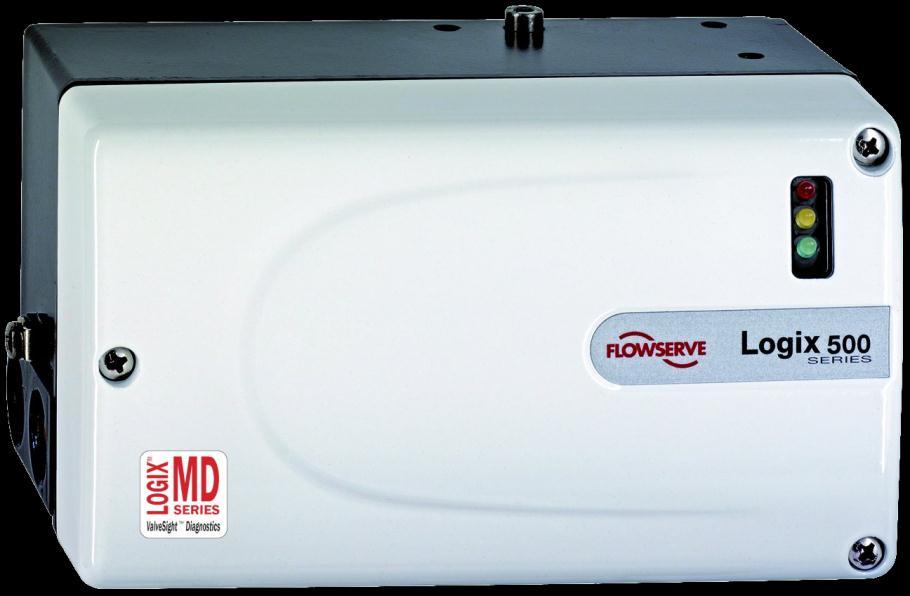


1 Device Description User Manual Logix 520MD Positioners
2 GENERAL INFORMATION... 3 INTRODUCTION... 3 QUALIFIED PERSONNEL... 3 USING THIS DOCUMENT... 3 TERMS CONCERNING SAFETY STATUS CMD SOURCE CHANGE COMMAND SOURCE DGTL CMD CMD CNTRL CMD POSITION DEVIATION POSN CUTOFF TEMP PRESSURE LOCK PRESSURES POSITIONER SETTINGS ALERTS AND ALARMS CURRENT ALARMS ALARM MASKS EVENT HISTORY TEMPERATURE HISTORY HOUR METERS ADVANCE DIAGNOSTICS PARTIAL STROKE TEST CALIBRATION ACTUATOR/STROKE/FRICTION STROKE ANALOG OUTPUT ANALOG INPUT QUICK CALIBRATION STROKE CALIBRATION DATE ANALOG INPUT CALIBRATION DATE CALBRATIONS MODE CONFIGURATION DEVICE CONFIG POSITIONER TUNING PRESSURE CONTROL SOFT LIMITS & CUTOFF USER PREFERENCES DEVICE INFORMATION READ REGISTER WRITE REGISTER Flowserve Corporation 2
3 GENERAL INFORMATION Introduction This document provides detailed information about the function of the Logix 520MD+ Device Description (DD). The DD follows the protocol provided by the HART Communication Foundation. For more information about downloading, installing and using HART DDs, visit Qualified Personnel Qualified personnel are people who, on account of their training, experience, instruction and their knowledge of relevant standards, specifications, accident prevention regulations and operating conditions, have been authorized by those responsible for the safety of the plant to perform the necessary work and who can recognize and avoid possible dangers. In using this software, the position and operation of the related valves can be affected. Product users and maintenance personnel should thoroughly review the effects of any functions before applying those functions. Using This Document Terms Concerning Safety The safety terms DANGER, CAUTION and NOTE are used in these instructions to highlight particular dangers and/or to provide additional information on aspects that may not be readily apparent. To avoid possible injury to personnel or damage to valve parts, DANGER and CAUTION notes must be strictly followed. Modifying this product, substituting non-factory parts or using maintenance procedures other than outlined could drastically affect performance and be hazardous to personnel and equipment, and may void existing warranties. NOTE: indicates and provides additional technical information, which may not be very obvious even to qualified personnel. CAUTION: Indicates that minor personal injury and/or property damage can occur if proper precautions are not taken. DANGER: Indicates that death, severe personal injury and/or substantial property damage can occur if proper precautions are not taken. The features listed below are numbered to correspond to their location in the DD menu tree. Some menu items may not be available depending on positioner upgrade status and the presence of auxiliary cards. Flowserve Corporation 3
4 1 STATUS Allows access to real time command, position, temperature, and, if equipped, pressure data. Allows access to change the command source. 1.1 Cmd Source Displays the source of the command signal (analog or digital). 1.2 Change Command Source Use to change the command source to/from Analog/Digital. CAUTION: Changing Command Source may cause closure member movement. Please, follow all safety procedures. 1.3 Dgtl Cmd Enter the digital command value, in percent of full stroke. This variable is available only when the valve is being positioned by a digital command (digital source) rather than the 4-20 ma analog signal (analog source) Cmd Input 4-20 ma command expressed in percent of full scale Input. 1.5 Cntrl Cmd The modified command signal, in percent of full stroke, which actually sets the controlled position of the valve. Cntrl Cmd is generated after custom characterization, soft limits, and minimum position cutoff parameters are evaluated ma command and Cntrl Cmd can differ if custom characterization, soft limits, or minimum position cutoff are active. 1.6 Position Actual stem position in percent of full stroke, as measured by the position stem position transducer. 1.7 Deviation The difference between the modified position command (Cntrl Cmd) signal and the stem position signal expressed in percent of full stroke. Deviation = Cntrl Cmd - Position 1.8 Posn Cutoff Is the set point less or greater than the Minimum / Maximum Position Cutoff defined in the Soft Limit / Characterization Menu. 1.9 Temp Circuit board ambient temperature 1.10 Pressure Lock Indicates that the current position is within the Pressure Control Window Pressures Displays pressure values Supply Pressure Calibrated Supply pressure in user units used as basis for pressure sensor calibrations Port 1 ( % of Calibrated Supply) Port 1 pressure value in percent of calibrated supply maximum Supply ( % of Calibrated Supply) Supply pressure value in percent of calibrated supply maximum Positioner Settings View current positioner settings: Diagnostics capabilities, positioner model, and characterization Diagnostic Level Indicates whether positioner is Standard, Advanced, or Pro Positioner Model View whether the positioner has pressure sensors. 520 = No pressure sensors, 521 = Has pressure sensors Characterization Displays the position Characterization (linear, equal %, or custom) 2 ALERTS AND ALARMS Allows access to Current Alarms, Alarm Masks, Error History, Temperature History, and the Hour Meters. 2.1 Current Alarms View all current alarms, alerts, modes, and states Modes Initializing, Factory Reset State, Digital Command Mode, Squawk Mode, Jog Command Mode, Signature In Progress Positioner Status Position Deviation, Soft Stop Upper Limit, Soft Stop Lower Limit, Position Upper Limit, Position Lower Limit, MPC Active, Local Interface Disabled, Error History Reset Mechanical Actuation Ratio Warning, Pneumatic Inability to Fail Safe, Friction High Warning, Friction Low Warning, Friction High Alarm, Friction Low Alarm, Valve Cycles Warning, Valve Travel Warning. Flowserve Corporation 4
5 2.1.4 Calibration Stroke Cal in Process, Loop Cal in Progress, Pressure Cal in Progress, Analog Output Cal In Progress, Setting Inner Loop Offset Electronic Temperature High Warning, Temperature Low Warning, Shunt Voltage Reference Error, Piezo Voltage Error, Watch Dog Time Out, NV Ram Checksum Error, Electronic Unable to Fail Safe Pressure Supply Pressure Low Alarm, Supply Pressure High Alarm, Supply Pressure Low Warning, Port 1 Value Out of Range, Port 1 Range too Small, Pneumatic Leak Warning Inner Loop Pilot Relay Warning, Pilot Relay Alarm, Spool Cycles Warning, Spool Travel Warning, Hall Sensor Upper Position, Hall Sensor Lower Position Outer Loop Feedback Range Too Small, Position Out Of Range 0%, Position Out Of Range 100%, No Motion Time Out, Non- Settle Time Out, Inner Loop Offset Time Out, Jog Calibrate Set 100% Pos Command Loop Command Loop Range Too Small, Command Loop 100% Value Out Of Range, Command Loop 0% Value Out Of Range, Analog Output Range Too Small Configuration Pressure Sensor Board Present, Analog Output Board Present, Pressure Control Locked, Reversed POT Rotation. 2.2 Alarm Masks Allows access to available alarm and alert masks. Masks let you "turn off" unwanted alarms and alerts. Clear the check mark or set the value to OFF to mask off notifications of positioner modes Modes Mask Factory Reset State Calibrate, Signature In Progress Positioner Status Mask Position Deviation, Position Upper Limit, Position Lower Limit Mechanical Mask Actuation Ratio Warning, Pneumatic Inability to Fail Safe, Friction High Warning, Friction Low Warning, Friction High Alarm, Friction Low Alarm, Valve Cycles Warning, Valve Travel Warning Calibration Mask Stroke Cal in Process, Loop Cal in Progress, Pressure Cal in Progress, Analog Output Cal In Progress Electronic Mask Temperature High Warning, Temperature Low Warning, Shunt Voltage Reference Error, Piezo Voltage Error, Watch Dog Time Out, NV Ram Checksum Error, Electronic Inability to Fail Safe Pressure Mask Supply Pressure Low Alarm, Supply Pressure High Warning, Supply Pressure Low Warning, Port 1 Value Out of Range, Pneumatic Leak Warning Inner Loop Mask Pilot Relay Warning,Pilot Relay Alarm, Spool Cycles Warning, Spool Travel Warning, Hall Sensor Upper Position, Hall Sensor Lower Position. 2.3 Event History Allows access to last eight errors that occurred Last event nd event rd th th th th th Event Count Number of events since reset or power-up Reset Event Hist. NOTE: This procedure will erase the stored Event History. 2.4 Temperature History Displays the temperatures attained during operation Temp. Circuit board ambient temperature. Flowserve Corporation 5
6 2.4.2 Max Lifetime Maximum temperature reached since startup Min Lifetime Minimum temperature reached since startup Max Reset Maximum temperature reached since last reset Min Reset Minimum temperature reached since last reset Max Power Up Maximum temperature reached since last power up Min Power Up Minimum temperature reached since last power up. 2.5 Hour Meters Displays hours of operation Lifetime Number of hours positioner has been in operation Reset Number of hours positioner has been in operation since last reset Power Up Number of hours positioner has been powered up. 3 ADVANCE DIAGNOSTICS Allows access to Partial Stroke Test CAUTION: Starting the Partial Stroke Test will cause closure member movement. Please, follow all safety procedures. 3.1 Partial Stroke Test Parameters needed to run a partial Stroke Test and see results Start Partial Stroke Test Starts the partial stroke test Pst Time Breakaway Measured when the valve has moved ½ % from the starting position Pst Pressure Difference The pressure at the breakaway point Pst Time to Target Actual time it took for the valve to arrive within 2% of the final value Pst Time Limit Time used for pass fail criteria for the partial stroke Pst Result Pass/Fail indication of the test based on the reference time to target and the actual time to target. 4 CALIBRATION Gives access to Actuator/Stroke/Friction Calibration, Stroke Calibration, Analog Output Calibration, and Analog Input Calibration functions. 4.1 Actuator/Stroke/Friction Combined calibration that calibrates the internal pressure sensors of the positioner, the travel of the valve position (zero and span), and if auto tuning is enabled the gain values for the positioner are also calculated. Finally, a short sequence of movements allows the positioner to update a friction value for the valve assembly. Once set the friction value will continue to update on its own during normal operation. 4.2 Stroke Combined calibration that calibrates the travel of the valve position (zero and span) and, if auto tuning is enabled, the gain values for the positioner are also calculated. 4.3 Analog Output The Analog output calibration is only available for positioners that have been supplied with the analog output module installed in the positioner. The Analog output is updated to match the stroke calibration of the positioner automatically every time a stroke calibration is done. This calibration is required if the 4-20 ma signal from the positioner needs to be spanned to something other than 4-20 ma. This option is also used to reverse the output if needed. Once setup properly, this calibration is usually not required for ongoing maintenance. 4.4 Analog Input The Analog input calibration is updated to match the stroke calibration of the positioner automatically every time a stroke calibration is done. This calibration is required if the 4-20 ma signal to the positioner needs to be spanned to something other than 4-20 ma. Once setup properly this calibration is usually not required for ongoing maintenance. Flowserve Corporation 6
7 4.5 Quick Calibration Set positioner to use the local interface to manually calibrate stroke. (Auto/Jog) 4.6 Stroke Calibration Date Date of calibration and initials of person who performed calibration. These should be entered at the time of calibration. 4.7 Analog Input Calibration Date Date of calibration and initials of person who performed calibration. These should be entered at the time of calibration. 4.8 Calbrations Mode This variable shows the state of the positioner during calibration. Each value of Calibrate corresponds to a specific stage in the calibration process: Calibrate = 0, Normal operation, Calibration OFF, position control enabled; Calibrate=1, Automatically calibrate stroke; Calibrate=2, Automatically calibrate actuator pressure sensors; Calibrate=3, acquire command counts with loop current at 0%; Calibrate=5, Moving valve to closed position, get Stem position at 0%; Calibrate=6, moving valve to open position, get stem position at 100%; Calibrate=7, Calibrating supply sensor; Calibrate=8, Calibrating Actuator Sensor, closing valve; Calibrate=9, Calibrating Actuator sensor, opening valve; Calibrate=11, quick-cal button has been pressed; Calibrate=12, Error occurred during Calibration 5 CONFIGURATION Allows access to Device Configuration, Positioner Tuning, Pressure Control, Soft Limits, Position Cut-off Limits, User Preferences, Device Information, Read Register, and Write Register. 5.1 Device Config Allows access to Local Interface, Air Action, 4-20 ma signal configuration, Characterization, Auto Tuning, Valve Stability, Stroke Calibration type, Reset to Factory Default, and whether the positioner has been calibrated since last reset Local Interface Enable or disable the Logix local panel Quick-cal and dip switches Air Action Displays the air action of the valve air to open (ATO) or air to close (ATC) Change Air Action Use to change air action from/to Air-to-Open/Air-to-Close Sig at Closed 4-20 ma signal to close the valve. CAUTION: Changing signal at closed may cause closure member movement. Please, follow all safety procedures Characterization Displays the position Characterization (linear, equal %, or custom Change Characterization Select characterization for stem movement. Choices are linear, equal %, and custom. CAUTION: Changing the characterization may cause closure member movement. Please, follow all safety procedures Auto Tune The positioner will calculate the new tuning parameter values when the stroke calibrated Valve Stability High friction automatically switches to pressure control. Low friction uses calculated tuning values Quick Calibration Auto will automatically calibrate. Use Jog to set positioner to use the local interface to manually calibrate the position of 100% open Reset Device Config This procedure will set all values for the positioner to its factory defaults. CAUTION: Resetting the device to factory default state will invalidate stroke calibration and cause closure member movement. You must perform Stroke Calibration for the positioner to work properly Calibrated Indicates whether the positioner has been calibrated after a reset or on initial startup. 5.2 Positioner Tuning Allows editing of positioner response tuning values. CAUTION: Changing positioner tuning values affect the control. Closure member may move suddenly or erratically. CAUTION: Changing the air action may cause closure member movement. Please, follow all safety procedures. Flowserve Corporation 7
8 5.2.1 Tuning values P - Gain I - Gain D - Gain Velocity Open Speed Limit Close Speed Limit IL Offset 5.3 Pressure Control Allows access to Pressure Control status and settings Enabled / Disabled pressure control Allows user to Enable/Disable pressure control. CAUTION: Enabling/Disabling Pressure Control will affect positioning control. Please, follow all safety procedures Pressure Control State Use Pressure Control function to control stem position in some high friction applictions Pressure Lock Indicates that the current position is within the Pressure Control window Window Size of the Pressure Control window. 5.4 Soft Limits & Cutoff Allows access to Soft Limit and Cut -off limits edit display Limits High Soft Limit Enter the Upper Soft Limit in percent of full stroke. The Modified Command Signal will not go above this limit Low Soft Limit Enter the Lower Soft Limit in percent of full stroke. The Modified Command Signal will not go below the limit Upr Pos Cutoff Point at which the stem will go to the full open position regardless of command value Lwr Pos Cutoff Point at which the stem will go to the full closed position regardless of command value. 5.5 User Preferences Allows access to Cycle Limits, Travel Limits, Position Travel Alerts Configuration, Units of Measure, and Burst Mode Control Valve Cycle / Travel Allows access to the valve cycle and travel information and settings Travel Length Length of travel. Usually set to 100% Cycle Count The Valve Cycle Counter counts the number of cycles of the valve stem since the last reset Cycle Limit Changing the Cycle Limit allows you to control the Cycle Limit warning level Change Cycle Limit Enter the number of cycles defined by the Valve Cycle Deadband that if exceeded will activate the Valve Cycle Limit alarm Cycle Deadband Cycle Deadband defines how large a stem movement is allowed before a cycle is counted Reset Cycle Count Valve Cycle Counter can be reset to zero Valve Travel Value of the Valve Travel Accumulator. The Valve Travel Accumulator measures the distance the valve stem has traveled since the last reset Travel Limit Enter the amount of travel defined by the Valve Travel Deadband that if exceeded will activate the Valve Travel Limit alert. Enter this value in the same engineering units as Stroke Change Travel Limit Changing the Travel Limit allows you to control the Travel Limit warning level Travel Deadband Valve Travel Deadband defines how large a stem movement is allowed before travel accumulator increases. Flowserve Corporation 8
9 Reset Travel Count The Valve Travel Accumulator can be reset to zero Position Alerts Allows you to change position alert settings. Controls the Position Upper and Lower Limit Alert Position Upper Alert Enter the Upper Position Alert set point in percent of full stroke. If the valve stroke exceeds this value, Upper Position Alert is activated Position Lower Alert Enter the Lower Position Alert set point in percent of full stroke. If the valve stoke falls below this value Lower Position Alert is activated Position Deviation Deadband Position Deviation Deadband entered in percent determines the minimum steady state difference which generates a Position Deviation Alert. This is entered as an absolute value. For example, if a deadband of +/- 2% is desired a value of 2 should be entered Position Deviation Time Position Deviation Time is the amount of time (entered in seconds) that the position deviation can exceed the Position Deviation Deadband before a Position Deviation Alert is generated Units Allows you to view and change the pressure, if equipped, and temperature units of measure Press Units Change Pressure Units Temp Units Burst Mode Settings Allows access to view and change burst settings Burst Mode State There are two possible states: enabled, disabled Command to Burst Allows the selection of the HART command to burst to the host. 5.6 Device Information Allows access to System Information, Positioner version information, Actuator information, Valve Trim information, and Valve Body information Positioner View HART information, change HART tag name, message, descriptor, and date Manufacturer Manufacturer identification code Device Device - References the type of Field Device, usually an advertised model number, that is unique to a single manufacturer Dev ID Field Device Identification - Uniquely identifies the positioner when combined with the Manufacturer Identification and Device Type, entered at the factory Elect SN Serial Number of the electronics control board Final Assm # Positioner Final Assembly Number - Number that is used for identification purposed, entered at the factory Device Tag Tag - Text that is associated with the positioner installation. This text can be used by the user in any way. A recommended use is as a unique label to a plant that correlates to a Field Device label: a plant drawing, or on a Control System. This variable is also used to address the device when communicating with HART. Enter up to 8 characters Message Message - Text that is associated with the positioner. This text can be used by the user in any way. Enter up to 32 characters Descriptor Descriptor - Text that is associated wit the positioner. This text can be used by the user in any way. Enter up to 16 characters Variables for Command 33 Allows the selection of individual variables to burst with HART command Date Date - calendar date that is stored in the positioner. This date can be used by the user in any way. Flowserve Corporation 9
10 5.6.2 Positioner Revs View the positioner internal version and revision information EC Major Rev Embedded code major version number EC Minor Rev Embedded code minor version number EC Build Date and Time Display the date embedded code was built Universal Rev Universal Revision - Revision of the Universal Device Description, that the Field Device conforms to, entered at the factory Hardware Rev Hardware Revision - Revision that corresponds to the electronics hardware of positioner, entered at the factory Fail Posn Motion Manuf Model Body Mat Body Size Pressure Class End Conn Pack Type Flow Dir. 5.7 Read Register Allows you to read a single register value from positioner. (Contact your Flowserve service technician for a variable map to correctly select values to read.) 5.8 Write Register Allows you to change internal variable values directly. (Contact your Flowserve service technician for a variable map to correctly select values to read.) Actuator Allows access to Actuator Manufacturer, Actuator Size and selection, etc. CAUTION: Changing variables using the write register may affect how the positioner controls the valve. Follow safety procedures. NOTE: Actuator size is used for friction calculations Select Actuator Info Manufacturer Model Positioner Action Type Spring Valve Trim Allows access to valve trim information and settings Stroke Length Stem Dia Character Trim Mat Type Size Leak Class Valve Body Allows access to valve body information. Flowserve Corporation 10
 4242 41181 999 North America (801) 489-2300 Asia + (65) 6879 8900 Flowserve Corporation has established industry leadership in the design and manufacture of its products.")
11 Bulletin FCD-LGENSF /13 To find your local Flowserve representative please use the Sales Support Locator System found at Or call Europe +43 (0) North America (801) Asia + (65) Flowserve Corporation has established industry leadership in the design and manufacture of its products. When properly selected, this Flowserve product is designed to perform its intended function safely during its useful life. However, the purchaser or user of Flowserve products should be aware that Flowserve products might be used in numerous applications under a wide variety of industrial service conditions. Although Flowserve can provide general guidelines, it cannot provide specific data and warnings for all possible applications. The purchaser/user must therefore assume the ultimate responsibility for the proper sizing and selection, installation, operation, and maintenance of Flowserve products. The purchaser/user should read and understand the (INSERT OFFICIAL USER INSTRUCTION TITLE) instructions included with the product, and train its employees and contractors in the safe use of Flowserve products in connection with the specific application. While the information and specifications contained in this literature are believed to be accurate, they are supplied for informative purposes only and should not be considered certified or as a guarantee of satisfactory results by reliance thereon. Nothing contained herein is to be construed as a warranty or guarantee, express or implied, regarding any matter with respect to this product. Because Flowserve is continually improving and upgrading its product design, the specifications, dimensions and information contained herein are subject to change without notice. Should any question arise concerning these provisions, the purchaser/user should contact Flowserve Corporation at any one of its worldwide operations or offices. For more information about Flowserve Corporation, contact or call USA Flowserve Corporation, Irving, Texas, USA. Flowserve is a registered trademark of Flowserve Corporation. Flowserve Headquarters 5215 N. O'Connor Blvd. Suite 2300 Irving, Tx Phone: Flowserve Corporation Flow Control 1350 N. Mt. Springs Parkway Springville, UT USA Phone: Fax: Flowserve S.A.S. 12, avenue du Quebec B.P Courtaboeuf Cedex France Phone: 33 (0) Fax: 33 (0) Flowserve Pte Ltd. 12 Tuas Avenue 20 Singapore Singapore Phone: Fax: Flowserve Australia Pty Ltd. 14 Dalmore Drive Scoresby, Victoria 3179 Australia Phone: Fax: Flowserve Ltda. Rua Tocantins, 128 São Caetano do Sul, SP Brazil Phone: Fax: Flowserve (Austria) gmbh Control Valves - Villach Operation Kasernengasse Villach Austria Phone: +43 (0) Fax: +43 (0) Flowserve (China) 585, Hanwei Plaza 7 Guanghau Road Beijing, China Phone: Flowserve India Controls Pvt. Ltd Plot # 4, 1A, E.P.I.P, Whitefield Bangalore Kamataka India Phone: Fax: Flowserve Essen gmbh Manderscheidtstr Essen Germany Phone: +49 (0) Fax: +49 (0) Kämmer Valves inc Parkway View Drive Pittsburgh, Pa USA Tel.: Fax: NAF Ab Gelbgjutaregatan 2 SE Linköping Sweden Phone: +46 (0) Fax: +46 (0) Flowserve Corporation 11
Specifications and information are subject to change without notice. Up-to-date address information is available on our website.
 www.smar.com Specifications and information are subject to change without notice. Up-to-date address information is available on our website. web: www.smar.com/contactus.asp LD302 - AssetView HMI LD302
USER INSTRUCTIONS. Installation Operation Maintenance. Logix 505si Series Digital Positioner. Experience In Motion
 Logix 505si Series Digital Positioner FCD LGENIM0505-00 03/09 User Instructions Logix 505si - LGENIM0505-00 03/09 USER INSTRUCTIONS Installation Operation Maintenance Experience In Motion 1 Table of Content
Specifications and information are subject to change without notice. Up-to-date address information is available on our website.
 www.smar.com Specifications and information are subject to change without notice. Up-to-date address information is available on our website. web: www.smar.com/contactus.asp FY302 AssetView IHM FY302 -
USER MANUAL. Intelligent Diagnostic Controller IDC24-A IDC24-AF IDC24-AFL IDC24-F IDP24-A * IDP24-AF * IDP24-AFL * IDP24-F * 1/73
 USER MANUAL Intelligent Diagnostic Controller IDC24-A IDC24-AF IDC24-AFL IDC24-F IDP24-A * IDP24-AF * IDP24-AFL * IDP24-F * *) Require software ID: DID-SW-001 1/73 Table of contents 1 General... 3 1.1
Series 3730 and Series 3731 EXPERTplus Valve Diagnostics with Partial Stroke Test (PST)
") Series 3730 and Series 3731 EXPERTplus Valve Diagnostics with Partial Stroke Test (PST) Application Positioner firmware for early detection of control valve faults giving maintenance recommendations. Valid
Series 3730 and Series 3731 EXPERTplus Valve Diagnostics with Partial Stroke Test (PST) Application Positioner firmware for early detection of control valve faults giving maintenance recommendations. Valid
Fisher FIELDVUE DVC6200f Digital Valve Controller PST Calibration and Testing using ValveLink Software
 Instruction Manual Supplement DVC6200f Digital Valve Controller Fisher FIELDVUE DVC6200f Digital Valve Controller PST Calibration and Testing using ValveLink Software The test procedure contained in this
Data Sheet T 8389 EN. Series 3730 and 3731 Types , , , and. EXPERTplus Valve Diagnostic
 Data Sheet T 8389 EN Series 3730 and 3731 Types 3730-2, 3730-3, 3730-4, 3730-5 and Type 3731-3 Electropneumatic Positioners EXPERTplus Valve Diagnostic Application Positioner firmware to detect potential
HART Communications Board
 - HART Communications Board (Highway Addressable Remote Transducer) User Manual Document No. Sensidyne, LP. 1000 112 th Circle N, Suite 100 St. Petersburg, Florida 33716 USA 800-451-9444 +1 727-530-3602
Neles ValvGuard VG9000H Rev 2.0. Safety Manual
 Neles ValvGuard VG9000H Rev 2.0 Safety Manual 10SM VG9000H en 11/2016 2 Neles ValvGuard VG9000H Rev 2.0 Safety Manual Table of Contents 1 General information...3 1.1 Purpose of the document... 3 1.2 Description
Operating Instructions EB EN. Series 373x Electropneumatic Positioner Type 373x-5 EXPERT + with FOUNDATION fieldbus communication
 Series 373x Electropneumatic Positioner Type 373x-5 EXPERT + with FOUNDATION fieldbus communication Fig. 1 Valve diagnostics with TROVIS-VIEW Operator Interface Operating Instructions EB 8388-5 EN Firmware
SIL Safety Manual. ULTRAMAT 6 Gas Analyzer for the Determination of IR-Absorbing Gases. Supplement to instruction manual ULTRAMAT 6 and OXYMAT 6
 ULTRAMAT 6 Gas Analyzer for the Determination of IR-Absorbing Gases SIL Safety Manual Supplement to instruction manual ULTRAMAT 6 and OXYMAT 6 ULTRAMAT 6F 7MB2111, 7MB2117, 7MB2112, 7MB2118 ULTRAMAT 6E
MP15 Jockey Pump Controller
 Setup and Operating Instructions MP15 Jockey Pump Controller This manual provides general information, installation, operation, maintenance, and system setup information for Metron Model MP15 Jockey Pump
The benefits of the extended diagnostics feature. Compact, well-proven, and flexible
 ABB MEASUREMENT & ANALYTICS TECHNICAL INFORMATION PositionMaster EDP300 Extended Diagnostics Compact, well-proven, and flexible The benefits of the extended diagnostics feature The PositionMaster EDP300
Installation Operation Maintenance
 682 Seal Cooler New generation seal cooler to meet and exceed the seal cooler requirements stated in the 4th Edition of API Standard 682 Installation Operation Maintenance Experience In Motion Description
Valve Communication Solutions Axiom
 Axiom Detect automated valve problems... before they shut down your process Reasons for Automated On/Off Valve Failures Monitor Fail Solenoid Fail Actuator Fail Coupling Break Too Slow Leaking Sticking
Logix 510si Digital Positioner
 Logix 510si Digital Positioner ADK041400E - 04.03 This product meets the requirements of 1 Table of Content Page 1 General Information... 3 2 Unpacking... 4 3 Logix 510si Overview... 5 4 Specifications...
EL-O-Matic E and P Series Pneumatic Actuator SIL Safety Manual
 SIL Safety Manual DOC.SILM.EEP.EN Rev. 0 April 2017 EL-O-Matic E and P Series Pneumatic Actuator SIL Safety Manual schaal 1:1 EL Matic TM EL-O-Matic E and P Series DOC.SILM.EEP.EN Rev. 0 Table of Contents
Partial Stroke Testing for SRD991 and SRD960
 Technical Information 09.11 TI EVE0105 PST-(en) Partial Stroke Testing for SRD991 and SRD960 Final control elements in Emergency Shutdown (ESD) applications such as ON-OFF-, Blow Down and Venting-Valves
Autocalibration Systems for In Situ Oxygen Analyzers
 Product Data Sheet PDS 106-340AC.A01 February, 2006 SPS 4001B, IMPS 4000 and MPS 3000 Autocalibration Systems for In Situ Oxygen Analyzers Cost-effective autocalibration systems for installations ranging
Design DSA Steam-Atomized Desuperheater
 Instruction Manual DSA Desuperheater Design DSA Steam-Atomized Desuperheater Contents Introduction............................... 1 Scope of Manual......................... 1 Description..............................
PTG100 Precision Test Gauge
 PTG100 Precision Test Gauge User Manual PD1007 Rev B 03/28/2014 Palmer Instruments Inc. 234 Old Weaverville Road Asheville, NC 28804 Toll Free: 800-421-2853 Phone: 828-658-3131 Fax: 828-658-0728 Email:
Fisher 2625 and 2625NS Volume Boosters
 Product Bulletin D200071X012 2625 and 2625NS Volume Boosters Fisher 2625 and 2625NS Volume Boosters A Fisher 2625 or 2625NS volume booster (figure 1) is used in conjunction with a positioner on a throttling
PositionMaster EDP300 Extended Diagnostics. Compact, well-proven, and flexible
 Change from one to two columns Technical Information TI/EDP300_ED-EN Rev. A PositionMaster EDP300 Extended Diagnostics Compact, well-proven, and flexible The benefits of the extended diagnostics feature
Installation and Operation Manual
 Manual Static pressure transducer with controller Differential static pressure transducer with analog output and optional PI control mode Large diaphragm element with differential transformer Transducer
A TECHNICAL REFERENCE
 A TECHNICAL REFERENCE FOR CAREL DCM CONTROLLERS DIGITAL COMPRESSOR MODULE CANADIAN HEAD OFFICE AND FACTORY USA HEAD OFFICE AND FACTORY CANADIAN EASTERN FACTORY 1401 HASTINGS CRES. SE CALGARY, ALBERTA T2G
WARNING FOR YOUR SAFETY
 ! OWNER S MANUAL Power Alert AquaLink TRI Controller H0389100 REV A WARNING FOR YOUR SAFETY - This product must be installed and serviced by a licensed electrician in accordance with AS/NZ 3000-2007 and
Installation Instructions
 Installation Instructions Durametallic MD-200 Series Gas Dual Cartridge Canister Seal for Mixers and Agitators Experience In Motion 1 Equipment Check 1.1 Follow plant safety regulations prior to equipment
Race Screen: Figure 2: Race Screen. Figure 3: Race Screen with Top Bulb Lock
 Eliminator Competition Stand Alone Mode - Instruction Manual Main Menu: After startup, the Eliminator Competition will enter the Main Menu. Press the right/left arrow buttons to move through the menu.
Hydro-Control V User Guide
 Hydro-Control V User Guide Hydronix Part no: HD0193 Version 2.3.0 Revision date: July 2006 1 COPYRIGHT Neither the whole or any part of the information contained in nor the product described in this documentation
Model GFC 7000T CO 2 Analyzer (Addendum to GFC 7000TA Manual, PN 07272)
") Manual Addendum Model GFC 7000T CO 2 Analyzer (Addendum to GFC 7000TA Manual, PN 07272) P/N M07273 DATE 06/11/13 TELEDYNE ELECTRONIC TECHNOLOGIES Analytical Instruments 16830 Chestnut Street City of Industry,
Manual Addendum Model GFC 7000T CO 2 Analyzer (Addendum to GFC 7000TA Manual, PN 07272) P/N M07273 DATE 06/11/13 TELEDYNE ELECTRONIC TECHNOLOGIES Analytical Instruments 16830 Chestnut Street City of Industry,
Pneumatic high-pressure controller Model CPC7000
 Calibration technology Pneumatic high-pressure controller Model CPC7000 WIKA data sheet CT 27.63 Applications Automotive and avionics industry Industry (laboratory, workshop and production) Transmitter
USER INSTRUCTIONS. NAF Duball DL Ball Valves. Installation Operation Maintenance. Experience In Motion. flowserve.com
 USER INSTRUCTIONS NAF Duball DL Ball Valves FCD NFENIM4167-01-A4 01/17 Installation Operation Maintenance 1 Experience In Motion Contents SAFETY 3 1 General 3 2 Lifting 4 3 Receiving Inspection 4 4 Installation
ACV-10 Automatic Control Valve
 ACV-10 Automatic Control Valve Installation, Operation & Maintenance General: The Archer Instruments ACV-10 is a precision automatic feed rate control valve for use in vacuum systems feeding Chlorine,
Datasheet: K-30 ASCII Sensor
 Datasheet: K-30 ASCII Sensor The K30 ASCII sensor is a low cost, infrared and maintenance free transmitter module intended to be built into different host devices that require CO2 monitoring data. The
User Manual. asense VAV. CO 2 / temperature sensor with built-in general purpose controller
 Gas and Air Sensors User Manual asense VAV CO / temperature sensor with built-in general purpose controller General The IAQ-sensor product asense VAV is used to measure indoor air carbon dioxide concentration
PART 5 - OPTIONS CONTENTS 5.1 SYSTEM EXPANSION 5-3
 PART 5 - OPTIONS CONTENTS Para Page 5.1 SYSTEM EXPANSION 5-3 5.2 SENSORS 5-3 5.2.1 Trim Angle Sensor 5-3 5.2.2 Mast Rotation Sensor 5-3 5.2.3 Heel Angle Sensor 5-3 5.2.4 Barometric Pressure Sensor 5-3
Pneumatic high-pressure controller Model CPC7000
 Calibration technology Pneumatic high-pressure controller Model CPC7000 WIKA data sheet CT 27.63 Applications Healthcare and avionics industry Industry (laboratory, workshop and production) Transmitter
BAROMETER PRESSURE STANDARD PRESSURE CONTROLLER
 BAROMETER PRESSURE STANDARD PRESSURE CONTROLLER Features ±0.01% FS Measurement & Control Accuracy ±0.001% /ºC Thermal Stability Pressure Ranges from ±1 psid to 1200 psia Applications Barometric Measurement
TANK MANAGER FOR TWO TANKS OPERATING MANUAL. 10/31/11 C-More T6C L color touch panel
 TANK MANAGER FOR TWO TANKS OPERATING MANUAL 10/31/11 C-More T6C L color touch panel 1 TABLE OF CONTENTS GENERAL...3 INSTALLATION...4 STONE TEST PROCEDURE...7 OPERATIONAL SUMMARY...7 AUTO CARBONATION...10
D10S/D20S Wall/Post Mount Inflator Quick Start Manual
 PART NUMBER SERIAL NUMBER D10S/D20S Wall/Post Mount Inflator Quick Start Manual Please read and save these instructions. Read carefully before attempting to assemble, install, operate or maintain the product
These Terms and conditions apply to audit trails incorporated in weighing and measuring devices and systems 1.
 Title: Terms and Conditions for the Approval of Metrological Audit Trails Effective Date: 2006-03-16 Page: 1 of 9 Revision: 1.0 Application These Terms and conditions apply to audit trails incorporated
Installation, Operation, & Maintenance Manual NX Seal Cooler
 Installation, Operation, & Maintenance Manual NX Seal Cooler 1 1. INTRODUCTION 1.1 About this Manual This manual is intended to ensure a safe installation and operation of the NX sealcooler. All involved
SCIENTIFIC DATA SYSTEMS, INC. Depth Tension Line Speed Panel. DTLS Manual
 SCIENTIFIC DATA SYSTEMS, INC. Depth Tension Line Speed Panel DTLS Manual This document contains proprietary information. Copyright 2015 Scientific Data Systems, Inc. All rights reserved. 1 Depth Tension
Safety Manual. Process pressure transmitter IPT-1* 4 20 ma/hart. Process pressure transmitter IPT-1*
 Safety Manual Process pressure transmitter IPT-1* 4 20 ma/hart Process pressure transmitter IPT-1* Contents Contents 1 Functional safety 1.1 General information... 3 1.2 Planning... 4 1.3 Instrument parameter
TR Electronic Pressure Regulator. User s Manual
 TR Electronic Pressure Regulator Page 2 of 13 Table of Contents Warnings, Cautions & Notices... 3 Factory Default Setting... 4 Quick Start Procedure... 5 Configuration Tab... 8 Setup Tab... 9 Internal
UBEC 1AT. AUTO TANK Fill System Installation, Operation, & Setup Instructions
 Document Number: XE-ATA5PM-R1A UBEC 1AT AUTO TANK Fill System 08899155 Installation, Operation, & Setup Instructions Rev170906-EB-FRC PHYSICAL: 1302 WEST BEARDSLEY AVE ELKHART, IN 46514 WWW.ELKHARTBRASS.COM
VOLUME BOOSTER RELAYS YT-300 / 305 SERIES
 VOLUME BOOSTER RELAYS YT-300 / 305 SERIES PRODUCT MANUAL VERSION 1.02 Contents 1. Introduction 3 1.1 General information for the users. 3 1.2 Manufacturer Warranty 3 2. Product Description.. 4 2.1 General..
Burner Management System DEMO Operating instructions
 Burner Management System DEMO Operating instructions Burner Management System DEMO Operating Instructions Startup Summary - Normal startup is accomplished in four basic steps: 1. Leak Test a. Safety Valve
RESILIENT SEATED BUTTERFLY VALVES FUNCTIONAL SAFETY MANUAL
 Per IEC 61508 and IEC 61511 Standards BRAY.COM Table of Contents 1.0 Introduction.................................................... 1 1.1 Terms and Abbreviations...........................................
Richards Industries Basic Siemens PS2 Positioner Functions
 Basic Siemens PS2 Positioner Functions Wiring 1 Supply Pressure Use clean, dry instrument air for the supply pressure. In general, on valves that are normally closed, you need 35-40 psi of supply pressure
This manual provides necessary requirements for meeting the IEC or IEC functional safety standards.
 Instruction Manual Supplement Safety manual for Fisher Vee-Ball Series Purpose This safety manual provides information necessary to design, install, verify and maintain a Safety Instrumented Function (SIF)
CONTROL and INSTRUMENTATION
 CONTROL and INSTRUMENTATION COURSE 500: 5 DAYS: Max 8 Candidates This course covers the key aspects of current instrumentation and process control technology and is designed to enable maintenance personnel
RAM 4021-PR. Operation Manual. Worldwide Manufacturer of Gas Detection Solutions
 RAM 4021-PR Operation Manual Worldwide Manufacturer of Gas Detection Solutions TABLE OF CONTENTS RAM 4021-PR For Your Safety... 2 Description.... 2 Setup Mode.... 2 Lights/Alarms.... 3 Operation.... 4
Ultima. X Series Gas Monitor
 Ultima X Series Gas Monitor Safety Manual SIL 2 Certified " The Ultima X Series Gas Monitor is qualified as an SIL 2 device under IEC 61508 and must be installed, used, and maintained in accordance with
Fisher DVI Desuperheater Venturi Inline
 Instruction Manual DVI Desuperheater Fisher DVI Desuperheater Venturi Inline Contents Introduction... 1 Scope of Manual... 1 Description... 1 Principle of Operation... 2 Installation... 3 Operating Instructions...
Type 4660 High-Low Pressure Pilot
 Product Bulletin Type 4660 High-Low Pressure Pilot The Type 4660 pneumatic high-low pressure pilot (figure 1) activates safety shutdown systems for flowlines, production vessels, and compressors. This
Safety Manual VEGAVIB series 60
 Safety Manual VEGAVIB series 60 Contactless electronic switch Document ID: 32002 Contents Contents 1 Functional safety... 3 1.1 General information... 3 1.2 Planning... 4 1.3 Adjustment instructions...
Using Modbus Protocol with the ALTUS Net Oil Computer. Instruction Manual
 Using Modbus Protocol with the ALTUS Net Oil Computer Instruction Manual November 2000 Using Modbus Protocol with the ALTUS Net Oil Computer Instruction Manual November 2000 For technical assistance,
Doc. no.dit om005 PRODUCT NAME. IO-Link/ELECTRO-PNEUMATIC REGULATOR. MODEL / Series / Product Number ITV*0*0-IO****-X395
 Doc. no.dit-69900-om005 PRODUCT NAME IO-Link/ELECTRO-PNEUMATIC REGULATOR MODEL / Series / Product Number ITV*0*0-IO****-X395 This is the operation manual for the IO-Link compliant ITV. For other contents
RAM Operation Manual. Worldwide Manufacturer of Gas Detection Solutions
 RAM 4021 Operation Manual Worldwide Manufacturer of Gas Detection Solutions TABLE OF CONTENTS RAM 4021 For Your Safety... 2 Description.... 2 Setup Mode.... 2 Lights/Alarms.... 3 Operation.... 4 Calibration....
PREDICTING HEALTH OF FINAL CONTROL ELEMENT OF SAFETY INSTRUMENTED SYSTEM BY DIGITAL VALVE CONTROLLER
 PREDICTING HEALTH OF FINAL CONTROL ELEMENT OF SAFETY INSTRUMENTED SYSTEM BY DIGITAL VALVE CONTROLLER Riyaz Ali FIELDVUE Business Development Manager Fisher Controls Int'l., LLC. Marshalltown, IA 50158
Quickstart Installation Checklist (Please refer to operation manual for complete installation instructions)
") Quickstart Installation Checklist (Please refer to operation manual for complete installation instructions) 1. Uncrate blender from packaging. 2. Lift the blender and position over machine throat or floor
Quickstart Installation Checklist (Please refer to operation manual for complete installation instructions) 1. Uncrate blender from packaging. 2. Lift the blender and position over machine throat or floor
Control Valve Training Course Program
 Control Valve Training Course Program FINAL CONTROL AND REGULATE Control Valves LEARNINGPATH At the foundation of any process are the field devices that measure and control the flow of air, steam, water,
A Planning Guide for Effective Use HART Implementations. December 2012 (D103278X012)
") FIELDVUE Instruments A Planning Guide for Effective Use HART Implementations December 2012 (D103278X012) You've purchased a FIELDVUE instrument...now what??? How do you get the most value out of it? Where
FIELDVUE Instruments A Planning Guide for Effective Use HART Implementations December 2012 (D103278X012) You've purchased a FIELDVUE instrument...now what??? How do you get the most value out of it? Where
Safety Manual VEGAVIB series 60
 Safety Manual VEGAVIB series 60 NAMUR Document ID: 32005 Contents Contents 1 Functional safety... 3 1.1 General information... 3 1.2 Planning... 4 1.3 Adjustment instructions... 6 1.4 Setup... 6 1.5 Reaction
ECL Comfort 110, application 131 (valid as of software version 2.00)
") Operating Guide ECL Comfort 110, application 131 (valid as of software version 2.00) English version www.danfoss.com How to navigate? Adjust temperatures and values. Switch between menu lines. Select /
Operating Guide ECL Comfort 110, application 131 (valid as of software version 2.00) English version www.danfoss.com How to navigate? Adjust temperatures and values. Switch between menu lines. Select /
A4s Operation Manual
 A4s Operation Manual Safety Instruction Please read this manual carefully, also with related manual for the machinery before use the controller. For installing and operating the controller properly and
SSL. Smart Valve Positioner.
 Smart Valve Positioner Smartest valve control device meeting a dynamic performance and a precise setting with a piezoelectric technology and an optimized auto-calibration program Features Auto-Calibration
BUBBLER CONTROL SYSTEM
 BUBBLER CONTROL SYSTEM Description: The HDBCS is a fully automatic bubbler system, which does liquid level measurements in water and wastewater applications. It is a dual air compressor system with, air
For a similar sensor with o-ring mounting, refer to the 85BSD digital output pressure sensor.
 Weldable or threaded process fittings Pressure/temperature read-out Digital output ASIC calibrated Absolute, gage Cable/connector option Low power option DESCRIPTION The 85BSD is a small profile, media
BOTTOM HINGED FLOOD BARRIER
 BOTTOM HINGED FLOOD BARRIER Installation Instructions/Operation and Maintenance Manual Models: BH-590 Contact Information Table of Contents: Safety Precautions... 2 Product Information... 2 Manual Deployment
4194 Series Differential Pressure Indicating Controllers
 Product Bulletin 4194 Differential Pressure Controllers 4194 Series Differential Pressure Indicating Controllers The 4194 Series (low pressure) differential pressure indicating controllers (figure 1) show
Installation Instructions
 Durametallic SL-5000 and SL-5200 Seals Cartridge Slurry Seals Installation Instructions Experience In Motion SL-5000 and SL-5200 Cartridge Seals are complete preset seal assemblies which include the sleeve
CF8-W-Disp-CO. User manual. CO 2 / CO sensor with built-in general purpose controller
 User manual CF8-W-Disp-CO CO 2 / CO sensor with built-in general purpose controller General The IAQ-sensor product CF8-W-Disp-CO is used to measure indoor air carbon dioxide and carbon monoxide concentrations.
Autocalibration Systems For In Situ Oxygen Analyzers
 Product Data Sheet PDS 106-340AC SPS 4000, IMPS 4000, and MPS 3000 January, 1999 Autocalibration Systems For In Situ Oxygen Analyzers Cost-effective autocalibration systems for installations ranging from
The Ins and Outs of I/P Transducers
 The Ins and Outs of I/P Transducers By Mark B. Levine, ControlAir Inc. General description I/P transducers are versatile instruments that use an electrical control signal to proportionally regulate gas
YT-3300 / 3301 / 3302 / 3303 / 3350 / 3400 /
 Smart positioner YT-3300 / 3301 / 3302 / 3303 / 3350 / 3400 / 3410 / 3450 Series SIL Safety Instruction. Supplement to product manual July. 2015 YTC Ver 1.06 1 Table of contents 1 Introduction... 3 1.1
I/P Transducer Positioner Module
 I/P Transducer Positioner Module VRC P/N: 7958032 Installation, Operation and Maintenance Instructions 2.09 [53.1] 1.30 [32.9] 2.97 [75.5] 0.78 [19.8] 0.18 [4.4] 1.42 [36.1] n.18 MOUNTING HOLES (2) PLACES
GAS FUEL VALVE FORM AGV5 OM 8-03
 ALTRONIC AGV5 OPERATING MANUAL GAS FUEL VALVE FORM AGV5 OM 8-03 WARNING: DEVIATION FROM THESE INSTALLATION INSTRUCTIONS MAY LEAD TO IMPROPER ENGINE OPERATION WHICH COULD CAUSE PERSONAL INJURY TO OPERATORS
A4 Operation Manual. Fig.1-1 Controller Socket Diagram
 A4 Operation Manual Safety Instruction Please read this manual carefully, also with related manual for the machinery before use the controller. For installing and operating the controller properly and
Safety manual for Fisher GX Control Valve and Actuator
 Instruction Manual Supplement GX Valve and Actuator Safety manual for Fisher GX Control Valve and Actuator Purpose This safety manual provides information necessary to design, install, verify and maintain
Installation Instructions
 Installation Instructions BW Seals Uniseal Series Cartridge metal bellows single and dual seals Experience In Motion Description The Uniseal metal bellows seal series consists of: Uniseal I - Single seals
Roller AC Servo System
 Safely Instruction Roller AC Servo System HMI-15 User Manual Please read this manual carefully, also with related manual for the machinery before use the controller. For installing and operating the controller
RAM Operation Manual. Worldwide Manufacturer of Gas Detection Solutions
 RAM 4021 Operation Manual Worldwide Manufacturer of Gas Detection Solutions TABLE OF CONTENTS RAM 4021 For Your Safety... 2 Description.... 2 Setup Mode.... 2 Lights/Alarms.... 3 Operation.... 4 Calibration....
86BSD Backside Digital Output
 Stainless steel with O-ring seal Pressure/temperature read-out Backside digital output ASIC calibrated Absolute, gage Cable/connector option Low power option DESCRIPTION The 86BSD is a small profile, media
AMS 6916 Board mount pressure sensor with ratiometric analog output
 FEATURES Piezoresistive pressure sensor with amplified analog output Calibrated and temperature compensated Ratiometric voltage output, 0.5 4.5 V Digital signal conditioning, 12 bit output resolution Differential,
SSR. Smart Valve Positioner.
 Smart Valve Positioner Smartest valve control device meeting a dynamic performance and a precise setting with a piezoelectric technology and an optimized auto-calibration program Features Auto-Calibration
COMPARISON OF DIFFERENTIAL PRESSURE SENSING TECHNOLOGIES IN HOSPITAL ISOLATION ROOMS AND OTHER CRITICAL ENVIRONMENT APPLICATIONS
 COMPARISON OF DIFFERENTIAL PRESSURE SENSING TECHNOLOGIES IN HOSPITAL ISOLATION ROOMS AND OTHER CRITICAL ENVIRONMENT APPLICATIONS APPLICATION NOTE LC-136 Introduction Specialized spaces often times must
RAM 4021 Operation Manual
 RAM 4021 Operation Manual Worldwide Manufacturer of Gas Detection Solutions TABLE OF CONTENTS RAM 4021 For your safety...3 Description...3 Set-up mode...4 Annunciator lights/alarms...4 Operation...5 Calibration...6
Special Documentation Proline Promass 80, 83
 SD00077D/06/EN/14.14 71272498 Products Solutions Services Special Documentation Proline Promass 80, 83 Functional safety manual Coriolis mass flow measuring system with 4 20 ma output signal Application
2600T Series Pressure Transmitters Plugged Impulse Line Detection Diagnostic. Pressure Measurement Engineered solutions for all applications
 Application Description AG/266PILD-EN Rev. C 2600T Series Pressure Transmitters Plugged Impulse Line Detection Diagnostic Pressure Measurement Engineered solutions for all applications Increase plant productivity
IMVS2000v2 INSTALLATION OPERATING MANUAL MAN720. Integrated Monitoring Valve System. Copyright by BIFFI ITALIA. All rights reserved.
 IMVS2000v2 Integrated Monitoring Valve System INSTALLATION OPERATING MANUAL MAN720 Copyright by BIFFI ITALIA. All rights reserved. 1 4 11/02/2019 Fifth Issue Piacenti Battaglia 3 04/10/2018 Fourth Issue
Cover Page for Lab Report Group Portion. Head Losses in Pipes
 Cover Page for Lab Report Group Portion Head Losses in Pipes Prepared by Professor J. M. Cimbala, Penn State University Latest revision: 02 February 2012 Name 1: Name 2: Name 3: [Name 4: ] Date: Section
EasySas. The most advanced airlock electronics on the market. Recyclable product. Eco-design. Energy savings
 EasySas The most advanced airlock electronics on the market Eco-design Energy savings Recyclable product ELECTRONIC AIRLOCK MANAGEMENT SkySas range UniSas range CompacSas range An electronic management
RAM Operation Manual
 RAM 4021-1 Operation Manual Worldwide Manufacturer of Gas Detection Solutions TABLE OF CONTENTS RAM 4021-1 For Your Safety... 2 Description... 2 Setup Mode... 3 Lights/Alarms... 3 Operation... 4 Calibration...
eflo ELECTRONIC GAS FLOW METER OPERATIONS MANUAL
 eflo ELECTRONIC GAS FLOW METER OPERATIONS MANUAL Super Systems Inc. 7205 Edington Drive Cincinnati, OH 45249 513-772-0060 Fax: 513-772-9466 www.supersystems.com Super Systems Inc. USA Office Corporate
Model 130M Pneumatic Controller
 Instruction MI 017-450 May 1978 Model 130M Pneumatic Controller Installation and Operation Manual Control Unit Controller Model 130M Controller is a pneumatic, shelf-mounted instrument with a separate
Fail operational controls for an independent metering valve
 Failure mode and CMA valves Fail operational controls for an independent metering valve By: Michael Rannow email: michaelrannow@eaton.com Eaton Corporation, 7945 Wallace Rd. Eden Prairie, MN, 55347 As
User Manual. asense miii. / CO sensor with built-in general purpose controller
 Gas and Air Sensors User Manual asense miii CO 2 / CO sensor with built-in general purpose controller General The IAQ-sensor product asense miii is used to measure indoor air carbon dioxide and carbon
Neles trunnion mounted ball valve Series D Rev. 2. Safety Manual
 Neles trunnion mounted ball valve Series D Rev. 2 Safety Manual 10SM D en 1/2017 2 Neles trunnion mounted ball valve, Series D Table of Contents 1 Introduction...3 2 Structure of the D series trunnion