Subject: FRP Flange Design Ref: Thomas E. Graham, FRP Flanges for Process Pipe and Tanks, NACE, 1989
|
|
|
- Wilfred Evans
- 5 years ago
- Views:
Transcription


1 Britt Engineering Associates, Inc. Birmingham. Alabama September 30, 2018 Technical Note Subject: FRP Flange Design Ref: Thomas E. Graham, FRP Flanges for Process Pipe and Tanks, NACE, 1989 Background In we encountered some major flange failures that developed after about a year of service in a new bleach plant in NC. We performed the pipe stress analysis and provided assistance to the client s purchasing department during the bidding process. The low bidder offered the two piece flange even though integral flanges were specified the bid was accepted by the client. Also the client had experienced earlier problems with filament wound pipe and designated contact molded for all systems. Some of these flange problems are presented in the NACE paper along with incidences occurring at other plants that we were asked to analyze. Graham s paper was received with great interest and more than 100 copies were distributed to the attendees of the 1989 conference. A US University and a German University asked permission to use the information in a mechanical engineering class. NACE was contacted and gave approval to use the copyright material. Tom passed away some years ago but he conducted a number of seminars that were requested by several engineering firms. I believe the information is relevant today and may be of interest to engineers who are engaged in FRP piping system design. Flanges are one of the weak links in piping. Sincerely, Frank Britt PE Attachments: 1. Thomas E. Graham, FRP Flanges for Process Pipe and Tanks, NACE, ADDENDUM
2 FRP FLANGES for PROCESS PIPE and TANKS By THOMAS E. GRAHAM PE Consulting Engineer Presented at NACE Tenth Biennial MANAGING CORROSION WITH PLASTICS SYMPOSIUM November San Antonio, Texas
3 I. A B S T R A C T : This paper discusses details of manufacture, design, and application of contact molded flanges used in process piping and tanks and includes case histories and stress analysis of typical installations. Several failures will be discussed along with an analysis of the causes. Fabrication methods that have improved reliability and strength are presented. I I. I N T R O D U C T I O N : FRP flanges become necessary when joining pipe to tanks, pumps, valves and other equipment. This necessitates that FRP flanges match metallic flange standards in regards to bolting patterns and flange diameters. Due to the lower modulus of elasticity of FRP, along with other unique characteristics of fiberglass, this requires careful design and good fabrication techniques in order to achieve a seal under all service and environmental conditions. This paper deals with the requirements for FRP flanges and some designs that have worked and discusses some designs that have given problems in the past. Only contact molded flanges are considered. The main objective of a flanged joint is to affect a seal between the fiberglass pipe and the component to which it interfaces. To prevent leakage in a gasketed joint of any design, a bolt force is required to compress the softer gasket material so that the gasket seating surface fills the asperities of the contact faces of the two mating surfaces. Leakage is prevented only if the gasket material actually fills all depressions of the seal contact faces and the flange-hub assembly is sufficiently rigid that it is not distorted under the bending and torsional effects of the eccentric loading of the flange due to pressure, gravity, temperature, and bolt pre-load. This seal must be maintained throughout the life of the joint. Care must be exercised to prevent "blow-out" of the gasket due to low sealing stress, especially on flanges that have a very slick surface such as those laid up on a glass surface. The same results can occur if low durometer gaskets are used for high pressure service. Gaskets of 40 durometer should not be used in pressure service above 50 psi. (4) I I I. F R P F L A N G E R E Q U I R E M E N T S : A. PS-15-69: When an engineer needs to design a flange he has a limited number of resources to work with. NBS VOLUNTARY PRODUCT STANDARD PS has been, and continues to be, the main source for flange information for FRP process pipe and duct. But, PS begins in Section on flanges, with the statement "The use of flanges shall normally be kept to a minimum..." this doesn t give the engineer a very confident feeling about designing flanges. Then he looks in Table 5 for the thickness requirements and finds that the table is not filled out for large pipe diameters and high design pressures.(1) B. ASME SECTION VIII: Having run into this dilemma he turns to the ASME CODE SECTION VIII for BOILER AND PRESSURE VESSEL DESIGN only to find the following under ARTICLE 3-4 entitled FLANGES WITH OTHER THAN RING TYPE GASKETS, "The rules in Article 3-3 shall not be construed to prohibit the use of other types of bolted flanged connections, such as flanges using full-face gaskets or other means of fixing or clamping the
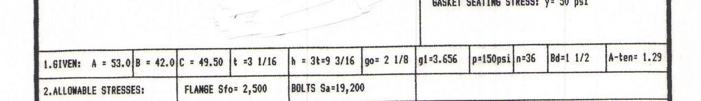
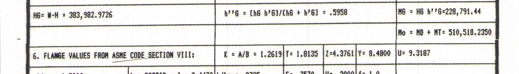
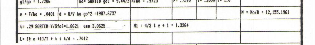
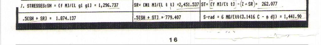
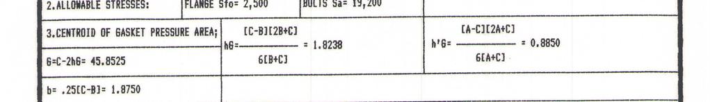
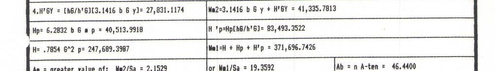
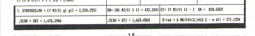
4 flange at the bolt circle to provide effective restraint against flange deflection. Such designs may be used provided they are designed in accordance with good engineering practice and the method of design is acceptable to the Inspector." [2] C. Taylor-Forge method of design: Fortunately there have been a number of efforts to use the Taylor-Forge flange design procedure for flat face flanges (3) normally used in FRP piping systems. The background for this method is in metallic flanges. FRP is an anisotropic material whereas the theoretical and testing work or flanges is based on orthotropic material. The question has to be raised as to whether the procedure is directly applicable. FRP flanges that have been designed and used in the past become a bench mark in evaluating the design methods for sizes and service conditions within this experience range. However, much needs to be done in the area of flange testing and analytical work to bring flanges within the realm of component design that is based on sound design standards that assures the engineer that his design and specification of flanges will result in a reliable system instead of a weak link. IV. FRP FLANGE DESIGN: TAYLOR-FORGE METHOD: Let us look at a typical flange to see what potential problems might arise and what variables the designer has to work with that can result in a reasonably sound design that can be fabricated with as little difficulty as possible. Figure 2 shows a flange that is typical of that used for FRP pipe. Since the bolting pattern is set by standards for metallic pipe that usually mates to the FRP flange and the flange OD is set within certain limits, that leaves the flange thickness and the hub reinforcing as variables that can be changed to meet the design requirements. There does not appear to be a restrictive limit on flange thickness except economy in design, but there is a limit on the hub reinforcement thickness because of the bolt location and a possible interference with the installation of bolts. (See the right side of Fig. 1.) The stresses that a flange undergoes are illustrated in figure 1 (see Appendix). There are four primary stresses that normally determine the design of the flange. These are, (1) S H, which is the longitudinal stress in the pipe wall and hub area, (2) S R which is the radial stress in the flange at the inside diameter of the flange, (3) S T which is the tangential or hoop stress acting on the cross sectional area of the flange and is maximum at the inside diameter of the flange acting in conjunction with S R, and (4) S R A D which is the radial stress at the section where the bolt holes remove material and weaken the section. (See the Appendix for nomenclature used in the analysis.) These stresses result from installation and operating conditions which includes loads from internal pressure, thermal effects, beam bending action, and preload from the bolts. Some of these loads are direct loads that cause axial tensile stress and some cause bending due to being eccentrically applied and result in bending stresses that can add to the axial tensile stress. For instance, all tensile loads that are transmitted through the flange to the mating flange must travel through the bolts since this is the only structural system that is capable of resisting these tensile loads. The loads are transmitted back to the flange skirt which results in bending stresses in the flange at the bolt locations. See Fig. 2 for flange loading assumptions for stress analysis. Now look at a typical design that illustrates a procedure for controlling stresses within limits that can be tolerated for fiberglass pipe. PS has a
5 foot note under TABLE 5 for flange thickness selection which states that, This Table is based on a factor cf safety cf 8 TO 1 and a flexural strength of 20,000 psi. This latter value is slightly under the minimum flexural strength for laminates of 3/8 inch and up (see Table 1), due to the manufacturing technique."[1] Other requirements of PS include the hub reinforcing length to be equal to four (4) times the flange thickness and the hub reinforced thickness equal to 1/2 the flange thickness as a minimum. The example problem will be performed on a 42 inch flange at 150 psi to illustrate the problems that occur in designing large diameter, high pressure flanges. The matter of hub reinforcement thickness is subject to some interpretation. Some have assumed that the requirement is that the tapered portion of the hub outside of the structural wall of the pipe be equal to 1/2 the flange thickness as indicated in ASTM Standard D 3299 for tanks, (5) Table 4 of this Standard shows this as a requirement for contact-molded flanged nozzles. However, the table only applies to 25 psi rating. If the same requirements are applied to 150 psi flanges, then the hub reinforcement extends out into the bolt hole area and much of it is cut out when spot-facing for the washers and bolts. This cutout material is not accounted for in the design procedure and thus the flange is weakened to a point below the strength indicated by the design procedure. PS does not specifically state that this is a requirement; but, when flanges are molded onto a piece of pipe, it becomes a requirement due to the nature of the fabrication. This type of flange has had problems in the past on some projects due to its two piece construction and the weakened area at the secondary bond interface. Our example problem is for an integral hub flange with one piece construction. Three cases are calculated based on the hub reinforcement requirements, (1) The hub dimension equal to 1/2 the flange thickness plus the pipe wall thickness, (2) the hub thickness equal to 1/2 the flange thickness, and (3) the hub thickness set to clear the spot face dimension as much as possible. The results are summarized in the following table: FLANGE THICKNESS MAX HUB THICKNESS INTEFERENCE BETWEEN HUB AND SPDTFACE MAX. STRESS CASE 1 CASE 2 CASE (S r ) (Sh) (S h ) It is evident when looking at these three cases that the hub thickness is critical in limiting the longitudinal stress at the hub-flange intersection. The flange thickness has to increase much more than the reduction in the hub thickness as shown in the three cases. The wall thickness for 150 psi rated HLU pipe necessitates that the spot-face at least get into the fillet area of the hub-flange junction, even when no hub is used as for case 3.
6 FRP FLANGES for PROCESS PIPE and TANKS V. DESIGNS THAT HAVE HAD PROBLEMS: A. Twenty inch stock line in bleach plant: The flanges involved were for 12 inch, 18" and 20" pipe. The project pipe fabrication was split into two orders to expedite pipe shipment. Part of the pipe was hand-lay-up and part was filament wound. All of the f langes were hand-lay-up with stub flanges except in several cases where pipe routing dictated that flanges be made onto some 90 degree elbows in order to fit in the cramped space (see Fig. 5.) The flanges were photographed and identified as to location. The flange construction for the pipe is shown in figures 3 and 4. One Fabricator laid the flange up directly on a straight pipe, section with the hub reinforcement thickness equal to one half the flange thickness when measured from the OD of the pipe (see Fig. 3). The pipe for this flange was 150 psi contact molded pipe and the flange thickness was 2 5/16 inches from face of flange to the spot-face surface. The spot-facing for the bolt holes cut into the hub area as shown in Figure 3b. The other fabricator laid the flanges upon tapered pipe or fittings as shown Figs. 4 and 5. An effort was made to minimize the hub thickness to avoid interference with the spot facing. There were numerous cracks at the centerline of the bolt holes in both directions as well as at the hub-flange intersection. The major cracks that led to leakage were in the flanges that were fabricated according to the technique shown in Fig 4, whereas the cracks in the flanges constructed according to Fig. 3 appeared to be superficial even though they were still of a concern. Much of this piping has since been replaced due to process up grades. A major failure occurred in a 20 inch flange that was made directly on a 90 degree elbow using the technique shown in Fig. 4 and 5. The line was a chlorinated stock line operating at 87 psi and 160 degrees F. It was located at the bottom of a 90 feet high chlorination tower and was a critical line, both from a process and safety view point. Fortunately, the failure was detected when it first began to leak badly and temporary reinforcement was added to prevent a catastrophic failure until a new elbow section could be fabricated using the technique shown in Fig. 3 and installed. Other contributing factors to the cracking and failure of the flanges were the thin, hard gasket material used along with the high bolt torques that were required to affect a seal. Flat face flanges with full face gaskets require a sealing stress ever the entire area of the gasket which results in a large bolt load if the gasket has a high durometer. A low durometer gasket should be used to reduce the seating stress of the gasket and thus result in lower bolt pre-load to effect and maintain a seal. B. Twenty four inch diameter water line: This case involved a 24 inch flange that failed due to bending stresses that resulted from unrestrained expansion joint that induced bending from pressure acting on a short offset. This flange was made up on a stub flange section without any hub reinforcement (see fig. 6). The system was designed for 25 psi, but actually operated at about 35 psi. The flange failed upon start-up because there was an unrestrained 6
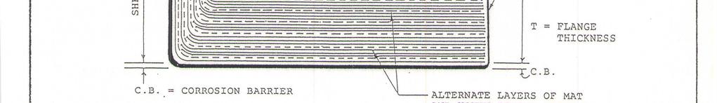
7 expansion joint at the pump flange which isolated the FRP pipe from pump vibrations. The yielding of the expansion joint under pressure created a high bending moment on the flange and it cracked immediately. It was replaced with a higher rated flange and restraints were added to the expansion joint. C. A sixty-six inch diameter cooling water line for a power plant: This flange was 6 inches thick and built on a piece of pipe with two piece construction. It developed cracking at the flange-hub junction when the restraining bolts at an expansion joint were left loose and the pressure caused the elbow to move and induced a high bending moment. Fortunately the flange was supported with a component support that acted as a semi-anchor and reduced the bending moment on the flange. D. A forty-two inch flange for a 100 psi salt water pumping station: These flanges were fabricated 4 inches thick using one piece construction. The Contractor called to complain about losing the gasket due to blow-out even though he had used the recommended torque supplied by the fabricator. The faces of the flange had been made on a glass table and were very smooth and slick. This resulted in blow-out of the gaskets even though the bolt torque was adequate for ordinary 100 psi service. After some calculations, it was decided to increase the bolt torque 50 foot pounds from the original 120 foot pounds specified. All the joints sealed except one. It was taken apart and some debris was found between the flanges that caused the leakage. The flanges sealed with the additional bolt loads without failure. VI. RECOMMENDED FLANGE DESIGN AND DETAIL: Fig. 7 shows a method of flange construction that the E n g i n e e r i n g d e p a r t m e n t h a s r e c o m m e n d e d a n d u s e d o n p r o j e c t s f o r m a n y years. This flange is a one piece, integral unit. The hub reinforcement is built up to a thickness equal to one half the flange thickness. Woven roving is made continuous from the shell and hub into the flange as well as the mat layers. The additional thickness of the flange is made up using donut shape sections of mat alternated between the layers of woven roving. Table 1 presents dimensions for this type of flange for sizes 2" through 42" and pressure ratings from 25 psi through 150 psi. In the calculations an attempt is made to minimize the interference between the spot-facing for the bolt holes and the hub reinforcement by setting the hub reinforcement to clear the spot-face diameter and determining the flange thickness required to bring the stresses ti: 2500 psi or less. A minimum hub shell thickness is set at 1/2 the flange thickness. Thus, for larger diameters and pressures, the hub still encroaches into the spot-face area for the bolts but is held to a minimum. It can be noted that the flange thicknesses are greater than those listed in Table 5 of PS for many flanges in the table. If the initial assumption had been based on using predetermined flange thicknesses and determining the hub thickness required the flange thickness would have been the same as in PS-15 where shown. Thus, it becomes obvious when performing analysis on FRP flanges that the geometric restraints for mating up to steel flanges dimensionally creates many problems. This is compounded by the fact that FRP analysis is being performed by procedures and with coefficients that were derived through many years of research, testing and design of steel flanges. The same testing and research needs to be performed on fiberglass flanges to determine the proper procedures, proportions and factors of
8 safety needed to provide reliable flanges. Such testing would need to be performed on full scale test samples under realistic conditions as they occur for FRP pipe installations. This would involve all sizes and pressure ratings acting under the combined effects of pressure and external bending on the flanges at design temperatures. Various gasket materials should be tested to determine the optimum durometer gasket to use and the optimum bolt torque to affect a maintainable seal. Table 2 gives the results of calculated bolt torques as determined by the analysis that Table 1 is based on. The calculated torques are based on the following: Maximum calculated bolt torque: Bolt load = W =.5 (Am+ Ab) Sa Bolt torque = (k P Bd] 1/12, where: Bolt torque is in ft. -lbs. k =.15 for lubricated bolts. Testing indicates that this value can vary between.10 and.23 P=single bolt load, lbs. B d = bolt diameter, inches Minimum calculated bolt torque: Bolt load = greater value of W m1, or W m2 (see Appendix for nomenclature and definition of terms.) Bolt torque = (k P B d ) 1/12 Recommended torque is: For 2" thru l6": Bolt torque = Min. torque + 2/3 (Max. torque - Min. torque), but not less than 25 ft. lbs. For 18" thru 42": Bolt torque = 1/2 (Min. torque + Max. torque). It should be noted that bolt torques for pressure piping flanges are affected by many factors, such as type of gasket, length and type of bolts, flange elastic modulus and rigidity, temperature, lubricity of bolts, etc. All gaskets creep after they have been loaded by the flanges which results in reduced bolt load. Creep is the tendency for the material to continue plastic deformation with no increase in load. This creep relaxation is greater at higher temperatures. Since most piping systems operate with a fluid temperature that is higher than the ambient temperature at installation, creep due to increased temperature is of concern. It has been reported that 90% of creep takes place in the first 24 hours at operating temperature. This makes inspection after start-up an important tool to assure proper bolt torques and other installation parameters have been performed properly. If leaks do occur, the system pressure should be relieved prior to retorquing the bolts. Re-torquing should be done in approximately 10 ft-lbs increments using the cross-torque method until the leak is stopped. If the maximum bolt torque value in table 2 is reached without stopping the leak, the engineer needs to be consulted to determine the cause to avoid over stressing the flange.
9 FRPSTUBFLANGEDIMENSIONSANDSTRESSES RATING PSI SIZE IN. A B C N STUB FLANGE DIMENSIONS Bd SF t h g0 g1 LEIN 511 STRESSES SR ST S-RAD /4 4 5/8 1 7/16 5/8 1 7/8 3/16 11/ , / /8 1 7/16 5/8 1 7/B 3/16 15/ , /2 8 5/8 1 7/16 3/4 2 1/4 3/16 23/ , /2 8 3/4 1 19/32 13/16 2 7/16 3/16 41/ , / /4 8 3/4 1 19/32 3/4 2 1/4 3/16 49/ , , /4 12 7/8 1 7/8 1 1/16 3 3/16 3/16 7/ , /8 1 7/ /16 1 1/ , , / /8 1 1/8 3 3/8 1/ , / / /8 1 1/4 3 3/4 1/4 1 1/ , / /8 2 3/8 1 3/ /4 7/8 12 1, , / /8 2 3/8 1 9/ /16 1/4 I 15 1, , / /4 2 5/8 1 5/8 4 7/8 1/4 1 1/8 15 1, , / /4 2 5/8 1 7/8 5 5/8 5/16 1 3/8 18 1, , / /2 3 1/8 2 7/16 7 5/16 3/8 1 1/2 21 1, , / /2 3 1/8 2 1/2 7 1/2 3/8 1 7/ , /4 4 5/8 1 7/16 5/8 1 7/8 3/16 11/32 6 1, , / /8 1 7/16 5/8 1 7/8 3/16 15/32 6 1,118 1, , /2 8 5/8 1 7/16 3/4 2 1/4 3/16 23/ , , /2 8 3/4 1 19/32 13/16 2 7/16 3/16 41/64 8 1,326 1, , / /4 8 3/4 1 19/32 3/4 2 1/4 1/4 49/64 8 1,381 2, , /4 12 7/8 1 7/8 1 1/16 3 3/16 1/4 7/8 10 1,365 1, , /8 1 7/ /4 1 1/ , , / /8 1 1/8 3 3/8 5/ ,677 1, , / / /8 1 1/4 3 3/4 5/16 1 1/4 12 1,336 1, , / /8 2 3/8 1 1/2 4 1/2 3/8 7/8 12 2,475 1, , / /8 2 3/8 1 9/ /16 3/ ,242 1, , / /4 2 5/8 1 5/8 4 7/8 7/16 1 1/8 15 2,503 1, , / /4 2 5/8 1 7/0 5 5/8 1/2 1 3/8 18 2,198 1, , / /2 3 1/8 2 7/16 7 5/16 5/8 1 1/2 21 2,385 1, , / /2 3 1/8 2 1/2 7 1/2 3/4 1 7/8 24 2,049 1, , /4 4 5/8 1 7/16 5/8 t 7/8 3/16 11/32 6 1, , / /8 1 7/16 5/8 1 7/8 3/16 15/32 6 1,677 1, , /2 8 5/8 1 7/16 3/4 2 1/4 3/16 23/32 6 1,176 1, , /2 8 3/4 1 19/32 13/ /4 41/64 8 1,944 1, , / /4 8 3/4 1 19/32 7/8 2 5/8 1/4 49/64 8 1,906 2, , /4 12 7/8 1 7/8 1 1/ /16 7/8 10 2,068 2, , /8 1 7/8 1 1/4 3 3/4 3/8 1 1/4 10 1,408 2, , / /8 1 1/4 3 3/4 3/ ,424 2, , / / /8 1 3/8 4 1/8 7/16 1 1/4 12 1,987 2, , / /8 2 3/ /2 7/8 12 2, , / /8 2 3/8 2 3/16 6 9/16 1/ , , / /4 2 5/8 2 1/2 7 1/2 5/8 1 1/8 15 2, / /4 2 5/8 2 7/8 Ii 5/8 3/4 1 3/8 18 2, / /2 3 1/8 3 3/8 10 1/ /2 21 2, , / /2 3 1/8 3 13/ / /8 24 2,499 % ,005 9
10 FRPSTUBFLANGEDIMENSIONSANDSTRESSES PRESSURE RATING PSI PIPE SIZE IN. A B C N STUB FLANGE DIMENSIONS Bd SF t h g0 gl LOTH SH STRESSES SR ST S-RAD /4 4 5/8 1 7/16 5/8 1 7/8 3/16 11/32 6 2,235 1, , / /8 1 7/16 5/8 1 7/8 3/16 15/32 6 2,236 2, , /2 8 5/8 1 7/16 3/4 2 1/4 1/4 23/32 6 1,554 2, , /2 8 3/4 1 19/32 7/8 2 5/8/8 1/4 41/64 8 2,504 2, , / /4 8 3/4 1 19/ /16 49/64 8 2,458 2, , /4 12 7/8 1 7/8 1 3/8 4 1/8 3/8 7/8 10 2,446 1, , /8 1 7/8 1 3/8 4 1/8 7/16 1 1/4 10 1,867 2,306 71B 1, / / / ,472 1, / / /8 1 5/8 4 7/B 9/16 1 1/4 12 2,508 2, , / /8 2 3/8 2 1/4 6 3/4 5/8 1 1/8 12 2,491 1, / /8 2 3/8 2 7/16 7 5/16 11/16 1 7/ , / /4 2 5/8 2 13/16 8 7/16 13/ / , / /4 2 5/8 3 1/4 9 3/ /8 18 2, / /2 3 1/8 3 13/ /16 1 1/4 1 29/ , / /2 3 1/8 4 5/ /16 1 7/16 2 5/ , /4 4 5/8 1 7/16 11/16 2 1/16 3/16 11/32 6 2,475 1,219 1,070 1, / /8 1 7/16 3/4 2 1/4 1/4 15/32 6 2,355 1,640 1,040 1, /2 8 5/8 1 7/16 13/16 2 7/16 1/4 23/32 6 1,856 2, , /2 8 3/4 1 19/32 1 1/4 3 3/4 5/16 41/64 8 2,483 1, , / /4 8 3/4 1 19/32 1 7/16 4 5/16 3/8 49/64 8 2,477 1, /4 12 7/8 1 7/8 1 13/16 5 7/16 7/16 29/ ,286 1, /B 1 7/8 1 1/2 4 1/2 1/2 1 1/4 10 2,263 2, , / /8 2 1/4 6 3/4 5/8 1 1/8 12 2, / / /8 2 3/8 7 1/8 11/16 1 1/4 12 2,502 1, / /8 2 3/8 2 1/2 7 1/2 3/4 1 1/4 12 2,429 1, / /8 2 3/8 2 3/4 8 1/4 7/B 1 3/8 15 2,488 1, / /4 2 5/8 3 3/16 9 5/ / , / /4 2 5/8 3 5/8 10 7/8 1 1/4 1 13/ , B / /2 3 1/8 4 3/ /16, 1 1/2 2 3/ , / /2 3 1/8 4 3/4 14 1/4 1 3/8 2 3/8 24 2, /4 4 5/8 1 7/16 3/4 2 1/4 3/16 3/8 6 2,212 1,120 1,202 1, / /8 1 7/16 7/8 2 5/8 1/4 15/32 6 2,444 1,324 1,086 1, /2 8 5/8 1 7/16 7/8 2 5/8 1/4 23/32 6 2,157 2, , /2 8 3/4 1 19/32 1 3/8 1 1/8 7/16 13/16 8 2,329 1, / /4 8 3/4 1 19/32 I 5/8 4 7/8 7/16 13/16 8 2,386 1, /4 12 7/8 1 7/8 1 15/ /16 1/2 31/ ,380 1, /B 1 7/8 1 13/16 5 7/16 5/8 1 1/4 10 2,495 1, / /8 2 3/8 7 1/8 3/4 1 3/ ,469 1, / / /8 2 11/16 8 1/16 13/ / ,422 1, / /8 2 3/8 2 11/16 8 1/16 15/ / ,422 1, / /8 2 3/8 2 7/8 8 5/ / ,477 1, / /4 2 5/8 3 5/ /16 1 1/4 1 21/ ,502 1, / /4 2 5/8 3 7/8 11 5/8 1 1/2 1 15/ ,452 1, / /2 3 1/8 4 1/ /2 1 7/8 2 1/4 21 2, / /2 3 1/B 5 1/ /8 2 1/8 2 9/ ,
11 FRP FLANGE BOLT TORQUE COMPARISON NOMINALDIAMETER PRESSURE RATING NUMBERBOLTS BOLT DIA. WASHER DIA. MASHER AREA BOLT LOAD BEARINGSTRESSCALC. BOLTTORO. BOLTTORQUESFROMBOOKS&CATALOGS MASHER GASKET MAX. MIN. REC. A/B C D E F 6 H /8 1 5/ BO _-_ /8 15/ B /8 15/ B 3/41 15/ /41 15/ /81 3/ , /8 1 3/
12 NOMINAL DIAMETER PRESSURERATIN NUMBER G BOLTS BOLT DIA. WASHER DIA. FRP FLANGE BOLT TORQUE COMPARISON WASHER AREA BOLT LOAD BEARINGSTRESSCALC.BOLTTORO. BOLTTORQUESFROMBOOKS&CATALOGS WASHERBASKET MAX. MIN. REC, A/B C DEFG H BO /82 1/ /82 1/ /42 1/ /42 1/ ' E / : /
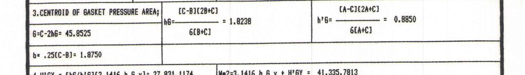
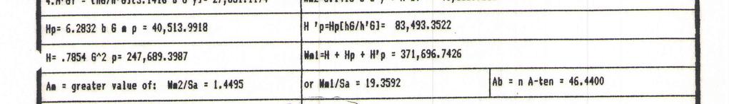
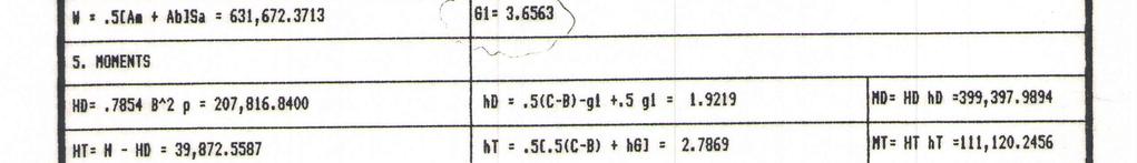
13 VII. CONCLUSIONS: FRP FLANGES for PROCESS PIPE and TANKS Poorly designed, fabricated or installed FRP flanges are a weak link in a piping system. Attention must be paid to many aspects of design, fabrication, and installation to be assured of a reliable flange. Short cuts or untried methods can lead to trouble. It does not pay to cut corners on flanges to save a few dollars if the piping system is critical to plant operations. Among the things that must be considered to obtain a good installation are, (1) Select conservative proportions for the flanges such as those in table 5 of PS Increase the thickness if the flange is to be mounted on a thin wall pipe such as filament wound pipe that has a structural wall below that listed in Table 3 of PS (2) Use one piece fabrication with as much integral hub reinforcement as practical on stub flanges. Avoid building flanges on pipe sections and fittings if possible. (3) Select a soft gasket with a Shore A or Shore A2 hardness between 40 and 70. (4) Use the proper bolt torque to seat the gasket without overloading the flange. Place a washer under the head and nut of the bolts that are in contact with fiberglass to avoid a bearing stress under the washer that exceeds 2500 PSI. (5) Provide good support close to the flange if it acts as a beam to avoid high bending moments on the joint. Supports located at the inflection point (point of zero moment would be ideal). Finally, (6) use good installation procedures such as keeping the sealing surfaces clean, don't allow the gasket to become twisted or crimped, lubricating the bolts, tighten the bolts using the cross torque method and incrementally tightening the bolts until the proper torque is obtained, and inspect the flanges after installation, hydro testing, and start-up to assure that there is no visible damage or leaking. Good flanges begin with good design and specification and are assured through continuous inspection throughout the fabrication and installation. The extra cost of a quality flange will provide peace of mind to the engineer and plant maintenance superintendent. The following symbols are used in the equations for the design of flat-faced flanges employing full-face gaskets. A = outside diameter of flange, in. (mm) A B = total cross sectional area of bolts at root diameter of thread or section of least diameter under stress, in. (mm) A m = total required cross sectional area of bolts, the greater of Wm 1 /S b or Wm 2 /S a, in. 2 (mm 2 ) B = inside diameter of flange, in. (mm) b = effective gasket width or joint contact surface seating width, in. (mm) C = diameter of bolt circle, in. (mm) d = shape factor for integral type flanges = d 1 = bolt hole diameter
14 e = shape factor = F/h o F = shape factor (Figure M ) f = hub stress correction factor (Figure M ) = 1 for calculated values less than 1 G = diameter of gasket load reaction g 0 = thickness of hub at small end g 1 = thickness of hub at back of flange H = hydrostatic end force H D = hydrostatic end force on area inside of flange H G = difference between bolt load and hydrostatic end force H Gy = bolt load for gasket yielding = bπgy H Gy = compression load required to seat gasket outside G diameter H p = total joint contact surface compression load = 2bπGmp H p = total adjusted joint contact surface compression for full face gasketed flange, lb = H T = difference between total hydrostatic end force and the hydrostatic end force area inside of flange = H H D h = length of hub, in. h D = radial distance from bolt circle to circle on which H D acts h G = radial distance from bolt circle to circle on which H G acts = radial distance from bolt circle to gasket load reaction = flange lever arm h T = radial distance from bolt circle to circle on which H T acts K = ratio of inside flange diameter to outside flange diameter L = length of flange including hub M = unit load, operating, lb = M max /B M a = moment under bolt up conditions M D = component of moment due to H D M G = component of moment due to H G M o = total moment M T = component of moment due to H T m = gasket factor N = number of bolts p = design pressure S a = allowable bolt stress at ambient temperature S b = allowable bolt stress at design temperature S Fa = allowable flange stress at ambient temperature
15 S Fo = allowable flange stress at design temperature S H = longitudinal hub stress S R = radial flange stress S RAD = radial stress at bolt circle S T = tangential flange stress T = shape factor (Figure M ) t = flange thickness t n = pipe wall thickness U = shape factor (Figure M ) V = shape factor (Figure M ) W a = flange design bolt load W m1 = minimum bolt loading for design conditions W m2 = minimum bolt loading for bolt up conditions Y = shape factor (Figure M ) y = gasket unit seating load Z = shape factor (Figure M )
16

17
18

19
20
21
22 21
23 24
24 23
25
26
Tutorial on Flange Qualification using CAEPIPE
 Tutorial on Flange Qualification using CAEPIPE This document explains the procedure on performing Flange Qualification using CAEPIPE. General Flange joints are essential components in all pressurized systems;
WELCOME to CAUx Local India 2018
 WELCOME to CAUx Local India 2018 Flange Design In Detail Prepared by Sachin Pol and Fauzan Badiwale Some Typical Flange Images 3 Some Typical Gasket Images 4 Flange Design As Per ASME Sec.VIII Div.1 Mandatory
THE PROCESS OF JOINT INTEGRITY
 BOLTED JOINTS A.333 THE PROCESS OF JOINT INTEGRITY To assist in managing a process, ask yourself the following questions: why, what, who, and how? Why do we need a Flange Joint Integrity program? This
Quality Plastic Pipe Fittings. Technical Data. Fabricated PVC Fittings IPS Class 100, 125, 160, 200 SCH 40 & SCH 80 Solvent Weld & Gasketed
 Quality Plastic Pipe Fittings Technical Data Fabricated PVC Fittings IPS Class 100, 125, 160, 200 SCH 40 & SCH 80 Solvent Weld & Gasketed Effective April 1, 2002 PIPE DIMENSIONS IPS-IRON PIPE SIZE Minimum
Flange Bolt Torquing. for Resistoflex Plastic-Lined Piping Products. Torquing. Retorquing. Hydrotesting. Annual retorquing
 Flange Bolt Torquing for Resistoflex Plastic-Lined Piping Products Torquing When assembling flange connections, always use a full complement of clean, new high strength A193-B7 bolting. If using stainless
Design and Optimization of Weld Neck Flange for Pressure Vessel
 V th International Symposium on Fusion of Science & Technology, New Delhi, India, January 18-22, 2016 ID: 2016-ISFT-430 Design and Optimization of Weld Neck Flange for Pressure Vessel Vinod Kumar 1, Vivek
IAPMO GUIDE CRITERIA FOR BALL VALVES IAPMO IGC PURPOSE
 INTERNATIONAL ASSOCIATION OF PLUMBING AND MECHANICAL OFFICIALS IAPMO GUIDE CRITERIA FOR BALL VALVES IAPMO IGC 157-20067 1 PURPOSE 1.1 The purpose of this standard is to establish an acceptable standard
OPENINGS AND REINFORCEMENTS 26
 ASME BPVC.VIII.1-2015 UG-35.2 UG-36 (4) It is recognized that it is impractical to write requirements to cover the multiplicity of devices used for quick access, or to prevent negligent operation or the
INSTALLATION, OPERATION AND MAINTENANCE GUIDE
 INSTALLATION, OPERATION AND Placement in Pipeline System When installing Process Development & Control s ElastoTITE Elastomer-Hinged Check Valves in a pipeline, a minimum of five pipe diameters should
Installation Instructions For Flat Seated Bolted Type RAH Series Disk Holders
 Installation Instructions For Flat Seated Bolted Type RAH Series Disk Holders RA Series Rupture Disks 1. WARNING a) Read the complete instructions before attempting to install the rupture disk and holder
Horizontal Bladder Tanks
 DATA SHEET Horizontal Bladder Tanks Features UL Listed and FM Approved for use with various ANSUL proportioners and foam concentrates 175 psi (12.1 bar) maximum allowable working pressure (design pressure)
Model MTB-ASME Vertical Bladder Tanks
 DATA SHEET Model MTB-ASME Vertical Bladder Tanks Features n UL Listed for use with various proportioners and foam concentrates n 175 psi (12.1 bar) maximum allowable working pressure (design pressure)
Model MTB-ASME Horizontal Bladder Tanks
 DATA SHEET Model MTB-ASME Horizontal Bladder Tanks Features n UL Listed and FM Approved for use with various proportioners and foam concentrates n 175 psi (12.1 bar) maximum allowable working pressure
Safety. April 2018 Supersedes all previous publications 2018 Chevron Phillips Chemical Company LP
 Technical Note 802 Leak Testing of Polyethylene Pipe For Municipal and Industrial Applications Part 1 Pre-Test Considerations Leak testing may be used to find leaks in a newly constructed or newly modified
pvc well casing & drop pipe
 C e r t a i nte e d pvc well casing & drop pipe P V C We l l P r o d u c t s Sure Fit PVC well casing and drop pipe have gained broad acceptance since their introduction almost 40 years ago. Today, due
Model MTB-ASME Vertical Bladder Tanks
 DATA SHEET Model MTB-ASME Vertical Bladder Tanks Features n UL Listed for use with various proportioners and foam concentrates n 175 psi (12.1 bar) maximum allowable working pressure (design pressure)
Installation, Operation and Maintenance Manual for Back Pressure Regulator
 Installation, Operation and Maintenance Manual for Back Pressure Regulator Model 8860 2009 Groth Corporation IOM-8860 Rev. B 12541 Ref. ID: 95565 Page 2 of 13 Table of Contents I. INTRODUCTION 3 II. DESIGN
Vertical Bladder Tanks
 DATA SHEET Vertical Bladder Tanks Features UL Listed and FM Approved for use with various ANSUL proportioners and foam concentrates 175 psi (12.1 bar) maximum allowable working pressure (design pressure)
DR.ING. CARLO AVANZINI PROFESSIONAL ENGINEER GRIP TEST REPORT NOVA SIRIA, ROLETTO, Premise
 GRIP TEST REPORT NOVA SIRIA, ROLETTO, 07.10.2013 1. Premise The present report covers the witnessing of the test conducted in the Nova Siria Factory in Roletto (Torino, Italy) to verify the behavior of
AWWA C504 COMPLIANT VALVES FROM 3 THRU 108
 AWWA C504 COMPLIANT VALVES FROM 3 THRU 108 PO Box 411 Berwick PA 18603 800-247-VALV www.crispinvalve.com 500 SERIES: Sizes 3-20 Available The K-Flo 500 Series is a heavy-duty resilient seated butterfly
TBV OPERATION AND MAINTENANCE MANUAL SERIES 2800: FLANGED BALL VALVE. For technical questions, please contact the following:
 TBV OPERATION AND MAINTENANCE MANUAL SERIES 2800: FLANGED BALL VALVE For technical questions, please contact the following: Engineering Department 1537 Grafton Road Millbury, MA 01527 Phone: (508) 887-9400
PVP2006-ICPVT
 Proceedings of PVP2006 / ICPVT-11: 11 th International Conference on Pressure Vessel Technology July 23-37, 2006, Vancouver, Canada PVP2006-ICPVT11-93020 DESIGN OF A LARGE RECTANGULAR FLANGE Bharat Batra,
Materials : Dichromate zinc plated steel flanges or AISI 316
 Size : Ends : Min Temperature : Max Temperature : DN 25 to 300 Flanges PN10/16-35 C + 90 C Max Pressure : 16 Bars (10 bars at 90 C) Specifications : Absorb vibrations and noise Linear and angular compansion
WHEATLEY WHEATLEY SERIES 500 SWING CHECK VALVE. Installation, Operation and Maintenance Manual
 WHEATLEY SERIES 500 SWING CHECK VALVE STANDARD INTEGRAL SEAT & OPTIONAL REMOVABLE SEAT 2" FP - 6" FP 150# - 1500# 8" FP - 12" FP 150# - 900# API 6D and B16.34 2" FP - 4" FP 5000# DRILLING PRODUCTION VALVE
Serving. Petrochemicals Power Semiconductor Waste Treatment Oil & Gas Transmission Lines Bulk Gas Plants
 Serving Petrochemicals Power Semiconductor Waste Treatment Oil & Gas Transmission Lines ulk Gas Plants Mining & Metals Pharmaceuticals Pulp & Paper Mills Sugar Mills Nuclear Desalinization Plants NOTES:
CERTIFICATION OF COMPLIANCE OF THE USER S DESIGN SPECIFICATION
 CERTIFICATION OF COMPLIANCE OF THE USER S DESIGN SPECIFICATION I, the undersigned, being experienced and competent in the applicable field of design related to pressure vessel requirements relative to
VALVES & MEASUREMENT
 VALVES & MEASUREMENT TBV OPERATION AND MAINTENANCE MANUAL SERIES 1100: THREE PIECE BALL VALVE For technical questions, please contact the following: Engineering Department 1537 Grafton Road Millbury, MA
ANDERSON GREENWOOD SERIES 9000 POSRV INSTALLATION AND MAINTENANCE INSTRUCTIONS
 Procedure-assembly-functional test and performance requirements 1 SCOPE 1.1 This document establishes the general procedure for assembly, functional testing and normal performance requirements of low Series
WHEATLEY Series 500 Swing Check Valve
 Document Number: TC003001-13 Revision: 02 WHEATLEY Series 500 Swing Check Valve Installation, Operation, and Maintenance Manual TABLE OF CONTENTS BILL OF MATERIALS...3 SCOPE...5 INSTALLATION AND OPERATION
INTRODUCTION TABLE OF CONTENTS
 2 INTRODUCTION Thank you for choosing Servometer to design and manufacture your unique, new electrodeposited bellows for your particular application. The definitions, formulas and design parameters inside
BUTTERFLY VALVES Series 800
 BUTTERFLY VALVES Series 800 WARNING Before proceeding read ALL instructions and become familiar with the equipment and associated drawings. Follow ALL applicable safety regulations and codes for pressurized
Torque Specifications
 SENR3130-10 Torque Specifications All Caterpillar Products S/N From the library of Barrington Diesel Club CONTENT General Information 01/07/2005 Introduction to Torque 01/07/2005 Torque-Turn 01/07/2005
Valve Inspection & Testing
 Inspection & Testing in accordance with API 598 Valve Inspection & Testing Shell Test (Body Hydro Test): - Each valve shall be tested in accordance with ASME B 16.34 for ASME valves. Shell test pressure
Rules for the Installation, Inspection and Testing of Air Reservoirs (Other than on Locomotives)
") Rules for the Installation, Inspection and Testing of Air Reservoirs (Other than on Locomotives) December 5, 1994 TM Rules for the Installation, Inspection and Testing of Air Reservoirs (Other than on
Rules for the Installation, Inspection and Testing of Air Reservoirs (Other than on Locomotives) December 5, 1994 TM Rules for the Installation, Inspection and Testing of Air Reservoirs (Other than on
ASME Boiler & Pressure Vessel Code Analysis of the 1497 MHz High-Current Cryomodule Helium Vessel
 1.0 Introduction ASME Boiler & Pressure Vessel Code Analysis of the 1497 MHz High-Current Cryomodule Helium Vessel Katherine Wilson 28 May 2007 To minimize the hazards associated with vacuum and pressure
FITTING IDENTIFICATION AMERICANT THREAD TYPES APPENDIX ALFAGOMMA // APPENDIX. Dash numers. NPTF (National Pipe Tapered Fuel)
") // FITTINGS GUIDelines FITTING IDENTIFICATION numers Most fluid piping system sizes are measured by dash numbers. These are universally used abbreviations for the size of component expressed as the numerator
// FITTINGS GUIDelines FITTING IDENTIFICATION numers Most fluid piping system sizes are measured by dash numbers. These are universally used abbreviations for the size of component expressed as the numerator
TEST SPECIFICATION NYT-909-C
 748 Starbuck Ave, Watertown, NY 13601 Phone: +1-315-786-5200 Engineering Fax: +1-315-786-5673 TEST SPECIFICATION NYT-909-C CODE OF TESTS FOR TESTING "AB" TEST RACK P/N 702546 & 702612 ISSUE NO. 5 1.0 THE
Flange Insulation. Gasket Basics. Why Gaskets Are Used:
 Flange Insulation Gasket Basics Why Gaskets Are Used: Gaskets are used to create a static seal between two stationary members of a mechanical assembly and to maintain that seal under operating conditions
Homestead Series 820 AWWA Butterfly Valves
 Homestead Series 820 AWWA Butterfly Valves Dependable Valves for Water & Wastewater Service BODY: The ductile iron body meets or exceeds the design strength requirements of the AWWA C504 standards. Flange
Vessels subject to External Pressure
 Basic principles of compressive force Vessels subject to External Pressure Before After The result of just air pressure! Presented by: Ray Delaforce Basic principles of compressive force Consider For a
Installation / Operation / Maintenance Manual KLINGER Reflex Level Gauge Type R 25
 Klinger Italy S.r.l Via De Gasperi, 88 20017 Rho, Mi - Italy Tel. +39 02 93333.1 Fax +39 02 93901312/3 www.klinger.it Telephone: +61 (08) 9350 1100 Facsimile: +61 (08) 9358 6200 ABN 95 008 679 838 Installation
SALCO PRODUCTS, INC. PRESSURE RELIEF VALVE STORAGE, INSTALLATION, OPERATING, MAINTENANCE/TESTING, AND INSPECTION INSTRUCTIONS
 STORAGE INSTRUCTIONS Until it is time to install a new or reconditioned valve on the car, the valve must be kept in its original packaging in order to protect it from dirt and damage. INSTALLATION INSTRUCTIONS
P-04 Stainless Steel Corrugated Hoses and Metal Bellows Expansion Joints
 Guideline No.P-04 (201510) P-04 Stainless Steel Corrugated Hoses and Metal Bellows Expansion Joints Issued date: 20 th October 2015 China Classification Society Foreword This Guideline is a part of CCS
COMMITTEE DRAFT. API 520 Part I 10 th Edition Ballot Item 2.1. This ballot covers the following item:
 This ballot covers the following item: API 520 Part I 10 th Edition Ballot Item 2.1 2008 12 Modify guidance to PRV datasheets (Line 17) to assist user s with determining the temperature to use for selecting
STANDARD SPECIFICATION FOR SPLIT TEES (HOT TAP MATERIAL)
") STANDARD SPECIFICATION FOR SPLIT TEES (HOT TAP MATERIAL) TEE (HOT TAPPING MATERIAL) S-04-02-040 Page 1 of 7 1.0 SCOPE This specification covers the basic requirements for the design, manufacture and supply
STANDARD SPECIFICATION FOR SPLIT TEES (HOT TAP MATERIAL) TEE (HOT TAPPING MATERIAL) S-04-02-040 Page 1 of 7 1.0 SCOPE This specification covers the basic requirements for the design, manufacture and supply
Vertical and Horizontal Bladder Tanks
 DATA SHEET Vertical and Horizontal Tanks Application The ANSUL bladder tank is one component in a balanced pressure proportioning system. Its operation requires no external power other than a pressurized
Spilt body Flange ball valve. TC-205MFF-PN1640 User Manual English Version. Document No: TC-205MFF-PN1640.Ur-manual. Date: 2007/04/2617. Version: 1.
 Spilt body Flange ball valve TC-205MFF-PN1640 Series PED Category I,II TC-205MFF-PN1640 User Manual English Version Use for company in Europe who will place the product on the market, please amend which
Series 8500 Expansion Compensators. Catalog 674H
 Series 8500 Expansion Compensators Catalog 674H 500 Laminated Bellows Expansion J Series 8500 on Joints Expansion Compensators Sizes 3/4" through 4" Threaded, welded, flanged and grooved steel pipe joints
The Powerful Sealing Calculation
 KLINGER expert 6.0 The Powerful Sealing Calculation The KLINGER expert 6.0 gasket design program is a versatile software to assist users in the selection of non-metallic gasket materials. www.klinger.co.at
CONTENTS Article NC-1000 Introduction Figures Article NC-2000 Material
 CONTENTS Foreword... xv Statements of Policy... xvii Personnel... xix Organization of Section III... xxxi Summary of Changes... xxxiii List of Changes in BC Order... xxxiv Article NC-1000 Introduction...
Annex G (normative) Requirements for Nondestructive Examination
 Requirements for Nondestructive Examination") Purchase API Spec online at http://www.techstreet.com/api Annex G (normative) G.1 General Requirements for Nondestructive Examination This annex specifies the requirements for NDE that shall be performed
Purchase API Spec online at http://www.techstreet.com/api Annex G (normative) G.1 General Requirements for Nondestructive Examination This annex specifies the requirements for NDE that shall be performed
TECHNICAL DATA OBSOLETE
 June 1, 2008 Foam 240a 1. DESCRIPTION The Chemguard Bladder Tank is one component in a balanced pressure foam proportioning system. It requires no external power, other than the water pressure to ensure
 AFL Industries, 1101 West 13 th St, Riviera Beach, FL 33404 PHONE: (561) 848-1826 FAX: (561) 848-9454 E-Mail: Sales@aflindustries.com AFL-STD MODEL OSV-4 SS INSTALLATION, OPERATION & MAINTENANCE BROCHURE
A parametric study of metal-to-metal contact flanges with optimised. geometry for safe stress and no-leak conditions
 A parametric study of metal-to-metal contact flanges with optimised geometry for safe stress and no-leak conditions M. Abid *, D. H. Nash a * Faculty of Mechanical Engineering, Ghulam Ishaq Khan Institute
// ADapters GUIDelines
 // ADapters GUIDelines ADAPTER SELECTION Selection of an appropriate ALFAGOMMA adapter for a given application depends on the fluid system operating parameters listed below and the tube material and wall
IMPORTANT: RECEIVING INSTRUCTIONS:
 Instruction Sheet Sidewinder Mechanical Bender IMPORTANT: RECEIVING INSTRUCTIONS: Visually inspect all components for shipping damage. If any shipping damage is found, notify carrier at once.shipping damage
DVS Technical - Codes and Bulletins. Table of Contents
 DVS 1904-1 (2010-02) Adhesive bonding of plastic in domestic installation Requirements on plants and personnel. 1 DVS 1904-2 (2010-02) Adhesive bonding of plastics in domestic installation Pipes and fittings
Preparation and Installation of the Sanitary BDI-FLX Sensor and Connection to the BDI-FLX Interface Cable
 GEP-6075 Rev. B 101574 Ref. I.D.: 16973 Preparation and Installation of the Sanitary BDI-FLX Sensor and Connection to the BDI-FLX Interface Cable WARNING USER SHOULD READ AND THOROUGHLY UNDERSTAND THESE
Atmospheric relief valve type 1100 Installation and maintenance instructions
 SAPAG 1. Description Sapag atmospheric relief valves type 1100 have been selected for installation because of their performance features, reliability and ease of maintenance. They are designed to protect
Apollo Standard Port, Full Port & One Piece Flanged Ball Valves Installation, Operation, & Maintenance Manual
 I854000.D Apollo Standard Port, Full Port & One Piece Flanged Ball Valves Installation, Operation, & Maintenance Manual Introduction This manual presents guidelines for the Installation, Operation and
3-PIECE BALL VALVE, 3600 PSI/ PN 248, WITH ISO DIRECT MOUNTING PAD 306M SERIES/ PED Category II
 3-PIECE BALL VALVE, 3600 PSI/ PN 248, WITH ISO DIRECT MOUNTING PAD 306M SERIES/ PED Category II 306M User Manual English Version Use for company in Europe who will place the product on the market, please
Unit 1, Fullerton Road Rotherham S60 1DJ. Tele: Fax:
 Unit 1, Fullerton Road Rotherham S60 1DJ Tele: 0845 601 333 6 Fax: 0845 601 333 7 info@fabricatedproducts.co.uk www.fabricatedproducts.co.uk Data Sheet 6.0 Rubber Pump Flexes All rubber bellows are suitable
Liquefied gas cargo tanks and process pressure vessels
 .1 -.3 Liquefied gas cargo tanks and process pressure vessels.1 General.1.1 The present texts give the general principles which are applied by Classification Societies for approval and survey of the relevant
29 SERIES - SAFETY VALVE
 INDUSTRIES, INC. 29 SERIES - SAFETY VALVE INSTALLATION, OPERATION, & MAINTENANCE Part I Document Number: ES1016-1 Revision Level: A Issued By: David Edmonds Date: 6/20/04 Approved By: Date: 10/4/04 Conbraco
Materials : Dichromate zinc plated steel flanges
 Size : Ends : Min Temperature : Max Temperature : DN 25 to 300 Flanges PN10/16-35 C + 130 C Max Pressure : 16 Bars up to DN150, 10 bars over Specifications : Absorb vibrations and noise Linear and angular
INSTALLATION & MAINTENANCE INSTRUCTION
 ARCHON Industries, Inc Liquid Level Gauges Models: BT-LLG ND-LLG INSTALLATION & MAINTENANCE INSTRUCTION Instruction No.: 1014.2 Revision Issued: 3/01/03 Approved: Engineering Manager Warning ONLY QUALIFIED
Team Insert Valve Sample Specification The Insert Valve shall conform to the following:
 Team Insert Valve Sample Specification The Insert Valve shall conform to the following: The Ductile Iron 250 p.s.i.g. Insert Valve shall be a Resilient Wedge Gate Valve designed for use in potable water,
Installation Instructions
 Installation Instructions TM Five Star Seal 80 Series Dual, Cartridge Mounted, Flexible Stator Pusher Seal Designed for General Service Applications 86 and 87 Experience In Motion Description The 86/87
Section GATE VALVES
 Section 02521 PART 1 GENERAL 1.01 SUMMARY This Section includes the furnishing and installation of gate valves for isolation and dead-end service as shown on Plans and as specified herein. 1.02 MEASUREMENT
Installation Instructions
 Installation Instructions Durametallic MD-200 Series Gas Dual Cartridge Canister Seal for Mixers and Agitators Experience In Motion 1 Equipment Check 1.1 Follow plant safety regulations prior to equipment
Берг АБ Тел. (495) , факс (495) Turning Ideas Into Engineered Solutions KAYDON RING & SEAL, INC.
 , факс (495) Turning Ideas Into Engineered Solutions KAYDON RING & SEAL, INC.") Turning Ideas Into Engineered Solutions RING & SEAL, INC. K-CBS Series Circumferential Barrier Seals Kaydon s high performance circumferential barrier seals back up DGS systems with performance & economy.
Turning Ideas Into Engineered Solutions RING & SEAL, INC. K-CBS Series Circumferential Barrier Seals Kaydon s high performance circumferential barrier seals back up DGS systems with performance & economy.
PVP Copyright 2009 by ASME
 Proceedings of PVP 009 009 ASME Pressure Vessel and Piping Division Conference July 6-30, 009, Prague, Czech Republic PVP009-7746 UPDATE OF THE TABULATED «M AND Y» VALUES IN THE NEW REVISIONS OF FRENCH
Perform Pressure & Leak Test, Tubing & Piping. Module 12306
 Perform Pressure & Leak Test, Tubing & Piping Module 12306 Instrumentation Trainee Task Module 12306 PERFORM PRESSURE AND LEAK TEST, TUBING AND PIPING Objectives Upon completion of this module, the trainee
MODEL WEIGH MODULE
 MODEL 65082 WEIGH MODULE INSTALLATION & OPERATING MANUAL P.O. Box 775 - Farmington, NH 03835 Tel: 603-755-3885 email: cands_nh@msn.com www.candscontrols.com Model 65023 Cantilever Beam Transducer Nickel-Plated
MONOLITHIC ISOLATING JOINTS: The Sealing Systems
 MONOLITHIC ISOLATING JOINTS: The Sealing Systems State of the Art and comparison among the several e systems. s NGPR0501 1 rev.0 dated 15-10-2005 - Copyright 2005 NuovaGiungas srl ITALY. Introduction The
Design and Analysis of Reactor Dish Vessel
 IJIRST International Journal for Innovative Research in Science & Technology Volume 3 Issue 11 April 2017 ISSN (online): 2349-6010 Design and Analysis of Reactor Dish Vessel Aniket D. Patil PG Student
GUKO FDA. einfach. gut. beraten.
 GUKO FDA Size : Ends : Min Temperature : Max Temperature : DN 25 to 300 Flanges PN10/16-25 C + 90 C Max Pressure : 16 Bars Specifications : Absorb vibrations and noise Linear and angular compansion Inner
Tank Blanketing Pressure Regulators RHPS Series
 www.swagelok.com Tank Blanketing Pressure Regulators RHPS Series Types: pressure reducing and vapor recovery 16L stainless steel construction 1/2, 1, and 2 in. end connections Working pressures up to 22
Engineering Data Sheet
 Page 1 of 6 CE MARKING AND THE PRESSURE EQUIPMENT DIRECTIVE 97/23/EC Valves must be installed into a well designed system and it is recommended that the system be inspected in accordance with the appropriate
Hardened Steel Washers
 USS (Type A Wide) Flat Washers Hardened Steel Washers Grade 8 S.A.E. Dimensions American Standard Lbs. Per No./Pcs. Gauge M Pcs. Per Lb. 3/16 9/16 1/4 18 (3/64) 2.8 361 1/4 3/4 5/16 16 (1/16) 6.7 149 5/16
CHEMICAL. Straight cut rod is provided in the materials listed below and includes nuts / washers.
 161 STRAIGHT CUT ROD Straight cut rod is provided in the materials listed below and includes nuts / washers. Straight Rod 22-1/2 Bent Rod A 307 THREADED ANCHOR ROD, ZINC PLATED (ASTM B633, CLEAR CHROMATE)
SUPPLY OF ISOLATION AND APPLIANCE VALVES PTS - APPLIANCE BALL VALVE
 PTS - APPLIANCE BALL VALVE 2 30.06.17 Issued for Tender AS ADE GS 1 12.04.17 Issued for Tender AS AD GS 0 06.03.17 Issued for Client s Comments AS AD GS Rev. Date Subject of revision Author Checked Approved
A new concept in the storage of liquefied chemical and petrochemical gases Zero leakage Zero fugitive emissions
 A new concept in the storage of liquefied chemical and petrochemical gases Zero leakage Zero fugitive emissions Introduction Industries involved in the handling of dangerous fluids have to answer increasing
DESIGN AND ANALYSIS OF PRESSURE VESSEL
 DESIGN AND ANALYSIS OF PRESSURE VESSEL Vrushali Dilip Solapurkar 1 Assistant Professor, Mechanical Engineering Department, Vadodara Institute of Engineering, Gujarat, India ABSTRACT This technical paper
INSTALLATION, OPERATION AND MAINTENANCE INSTRUCTIONS TYPE BV2-LD
 INSTALLATION, OPERATION AND MAINTENANCE INSTRUCTIONS TYPE BV2-LD 1. Storage & Protection 1.1. Storage The valves stay in the open position during the transportation. For incoming QC must check: a. Packing
FLANGED TWO-PIECE BALL VALVES
 INTRODUCTION This instruction manual includes installation, operation, and maintenance information for FNW flanged split-body ball valves. This manual addresses lever operated ball valves only. Please
DVS Technical Codes an Bulletins
 DVS Technical Codes an Bulletins DVS 1904-1 (2010-02) Adhesive bonding of plastics in domestic installation Requirements on plants and personnel... 1 DVS 1904-2 (2010-02) Adhesive bonding of plastics in
INSTALLATION, OPERATION & MAINTENANCE MANUAL
 INSTALLATION, OPERATION & MAINTENANCE MANUAL AWWA C500 SOLID WEDGE GATE VALVE 2 72 NRS and OS&Y Series 100 and Series 105 TABLE OF CONTENTS SECTION PAGE # Equipment List 2 General 3 Receipt and Inspection
Wafer Check Valve. Contents. User s Manual. (1) Be sure to read the following description of our product warranty 1
 Be sure to read the following description of our product warranty 1") Serial No. H-V066-E-3 Wafer Check Valve User s Manual Contents (1) Be sure to read the following description of our product warranty 1 (2) General operating instructions 2 (3) General instructions for
Serial No. H-V066-E-3 Wafer Check Valve User s Manual Contents (1) Be sure to read the following description of our product warranty 1 (2) General operating instructions 2 (3) General instructions for
Design of a Solid Wall Transonic Wind Tunnel
 Design of a Solid Wall Transonic Wind Tunnel David Wall * Auburn University, Auburn, Alabama, 36849 A solid wall transonic wind tunnel was designed with optical access from three sides to allow for flow
ROTATING DISK VALVES INSTALLATION AND MAINTENANCE 1. SCOPE 3 2. INFORMATION ON USAGE 3 3. VALVE TYPES 3 4. OPERATORS 5 5. VALVE CONSTRUCTION 6
 Sub Section INDEX Page Number 1. SCOPE 3 2. INFORMATION ON USAGE 3 3. VALVE TYPES 3 4. OPERATORS 5 5. VALVE CONSTRUCTION 6 6. INSTALLATION AND OPERATION 6 7. MAINTENANCE 8 8. REPAIR 9 9. ASSEMBLY 10 10.
Step 1: Step 2: psi psi
 General Tutorial on Evaluation of Nozzles by computing Local Shell Stresses as per WRC 537 and Stress Evaluation as per ASME Section VIII Division 2 using CAEPIPE Whenever Pressure Vessel or Heat exchanger
Other Si min/max. Cr min/max. 0.4/ / / / Bal.
 178.46 Specification 3AL seamless aluminum cylinders. (a) Size and service pressure. A DOT 3AL cylinder is a seamless aluminum cylinder with a imum water capacity of 1000 pounds and minimum service pressure
2003 WJTA American Waterjet Conference August 17-19, 2003 Houston, Texas Paper PIPE THREADS-WHAT IS THE LIMIT?
 23 WJTA American Waterjet Conference August 17-19, 23 Houston, Texas Paper PIPE THREADS-WHAT IS THE LIMIT? D. Wright, J. Wolgamott, G. Zink StoneAge, Inc. Durango, Colorado, U.S.A. ABSTRACT At present
Edward Valves Equiwedge Forged Gate Valve
 flowserve.com Edward Valves Equiwedge Forged Gate Valve Experience In Motion 1 New Hybrid Design resets Standards The new forged Equiwedge gate valve from Flowserve Edward valves is the ideal engineering
MUELLER. Mega-Lite Drilling Machine. Reliable Connections. table of contents PAGE. Equipment 2. Operating Instructions 3-4. Parts Information 5
 operating Instructions manual MUELLER Mega-Lite Drilling Machine table of contents PAGE Equipment 2 Operating Instructions 3-4 Parts Information 5 Travel Charts 6-11! WARNING: 1. Read and follow instructions
Installation Operation Maintenance
 682 Seal Cooler New generation seal cooler to meet and exceed the seal cooler requirements stated in the 4th Edition of API Standard 682 Installation Operation Maintenance Experience In Motion Description
310 SERIES TILT-TO-LOAD ROTATOR. The Specialist In Drum Handling Equipment
 OPERATOR S MANUAL FOR MORSE TILT-TO-LOAD DRUM ROTATOR SAFETY INFORMATION: While Morse Manufacturing Co. drum handling equipment is engineered for safety and efficiency, a high degree of responsibility
PC3_ and PC4_ Pipeline Connectors
 1283050/4 IM-P128-06 ST Issue 4 PC3_ and PC4_ Pipeline Connectors Installation and Maintenance Instructions 1. Safety information 2. Description PC30 shown 3. Installation 4. Welding of pipeline connector