Culvert Design An Overview of the NYS Highway Design Manual Chapter 8
|
|
|
- Peter Bennett
- 6 years ago
- Views:
Transcription


1 Seventeenth Statewide Conference on Local Bridges Culvert Design An Overview of the NYS Highway Design Manual Chapter 8 Tuesday, October 25, 2011 Training Session: Culvert Design, Analysis - talk 2 Presented by: Peter Van Kampen, P.E. NYSDOT Peter Van Kampen, P.E. NYSDOT Design Services Bureau Outline Culvert Basics Culvert Basics Site Considerations Design Criteria Conventional Culvert Selection & Design Culvert Protection/Channel Linings Plans Culvert Failures Resources Questions
, but may be an open conduit (e.g., an arch), installed to convey runoff collected in roadside channels, and natural channels such as streams, underneath an embankment.")
2 Culvert Chapter 8 HDM Types of Culverts - Shapes A culvert is usually a closed conduit (e.g., a pipe), but may be an open conduit (e.g., an arch), installed to convey runoff collected in roadside channels, and natural channels such as streams, underneath an embankment. Any single structure with a span greater than 20 ft (6.1 m) is a bridge. These structures require a different procedure for hydraulic analysis, and should be coordinated through the Regional Structures Group * Source - HDS 5 Culvert Materials Site Considerations Metal Steel (CSP) Structural plate, Aluminum, (CAP) Ductile iron (DIP) Concrete RCP (Class I Class V) Plastic Polyethylene SICPP Polyvinal chloride - PVC
3 What to Identify Stream Width. Size/Location of Up/Down Stream crossings. Stream Scour? Bed Material. Fish Bearing? Embankment Height. Photos to take View from roadway upstream and down stream. Inlet and outlet. Wingwalls and/or banks around inlet/outlet. Interior if possible. Any scour or erosion noted. Scaled reference of bed material. Design Criteria Or What do need to know before I select a culvert?
 Design Headwater (HDM & ACOE/DEC)* Outlet Velocity (Natural Velocity - Scour)*")

4 Design Size Criteria Constraints Design Storm Frequencies for Culverts and Channels Design Storm Frequency (Per HDM) Design Headwater (HDM & ACOE/DEC)* Outlet Velocity (Natural Velocity - Scour)* Aquatic Organisms (ACOE/DEC/Fish Wildlife) * Constraints defined/evaluated by designer HDM Chapter 8 page 8-21 Table 8.2 Roughness Coefficients n Conventional Culvert Design Reference HEC-22 Reference HDM, HEC-22, & HDS 5
5 Conventional Culvert Design Culvert Terminology Culvert defined as structure with a span less than or equal to 20 feet (6.1 m) Conventional culvert is a simple culvert placed on grade with standard headwall, end section inlet (improved inlets not covered here) Common shapes are box, circular, arch, and elliptical. Common materials are concrete, plastic, steel and aluminum. Hw Headwater EL Hd Headwater Elev. Inlet Invert Cut-off wall Roadway Embankment Outlet Invert H Head Loss Tailwater Elev. Tw Tailwater Cut-off wall Culvert Design Process 1. Calculate Q for design storm. 2. Select pipe material and shape for site. 3. Calculate tailwater depth 4. Calculate maximum allowable headwater 5. Size culvert 6. Check outlet velocity 7. Design outlet protection Calculate Q (flow) TR-20 / TR-55 HydroCAD Regression Equations StreamStats in NY _york.html Check your answers with historical sources if able.
 Stream conditions (Debris, Rocks, Ice movement) Chemical properties of project location (alkalinity/acidic nature of the surrounding soils, see HDM chapter 8.6.2.")
6 Material Considerations Design life/service life (HDM Chapter ) Stream conditions (Debris, Rocks, Ice movement) Chemical properties of project location (alkalinity/acidic nature of the surrounding soils, see HDM chapter ) Height of fills Environmental considerations (fish passage, mussels) Economics Calculate Tailwater Depth Use calculated flow rate from hydrologic analysis and basic open channel flow calculation for downstream conditions and linings Consider affect of major rivers & streams downstream that could influence tailwater. Determine if downstream culvert/bridge size limitations exist Document non-conforming features. Maximum Allowable Headwater Determination (Hw) 2 ft. below lowest shoulder edge. No damage to upland properties. No increase to water surface elevation than that allowed by floodplain regs (generally 1 ft). Headwater to pipe ratio: Diameter or Rise Maximum H w /D Ratio < 5 ft ft. 1.0 Culvert Sizing Minimum Culvert Size Minimum culvert size is 2 ft. Smaller diameters acceptable for shallow depths and utility conflicts 1 ft. is acceptable for driveway pipes and field entrances. Meets allowable Headwater criteria.

7 Culvert Sizing Determine Headwater Elevation Headwater is controlled by Inlet or Outlet control of the culvert. Inlet and outlet control influenced by several factors Design must be checked for inlet & outlet conditions to determine controlling feature. Culvert Sizing Inlet vs Outlet Control Inlet Control - Culvert is in inlet control when culvert is capable of delivering more flow than inlet will allow. Typically in supercritical flow. Outlet Control Culvert is in outlet control when the barrel losses are greater than the inlet loss. Typically in sub-critical flow. Culvert Sizing Inlet vs Outlet Control Culvert Sizing Inlet Control Factors Headwater depth determines pressure flow In general, we utilize calculations to determine this depth given other criteria Inlet Area determined from the culvert size selected. Inlet Shape Determined from culvert chosen

 Ke = 0.5 Grooved end projecting/ box with bevel (highest efficiency) Ke = 0.")

8 Culvert Sizing Inlet Control Factors Inlet edge configuration - The major factor in culvert performance Thin Edge Projecting Ke = 0.9 (poor efficiency) Thick walled inlet acts similar to square edge headwall & typical end sections (typical installation) Ke = 0.5 Grooved end projecting/ box with bevel (highest efficiency) Ke = 0.2 Bell end of projecting pipe upstream changes Ke from 0.7 to 0.2 See Table 223 of HDS #5 for additonal Ke factor values Find Ke value for given end treatments square 0.2 beveled Culvert Sizing Inlet Control Factors Beveling the inlet headwall is a cheap and effective way to improve hydraulic flow through the culvert 0.5 or


9 Beveled Headwall Sizing Culverts HDS-5 library_arc.cfm?pub_number=7&id=13 HY-8 software/hy8/ Culvert Sizing Outlet Control Factors Inlet or Outlet Control? All inlet control factors apply. Headwater will be controlled by barrel properties. Outlet Barrel shape, length, area, slope and roughness influence flow. Tailwater elevation determined by open channel flow calculations for downstream conditions. Inlet
 Outlet Velocity Calculations Inlet Control Determine")
/n ] Culvert outlet velocity is assumed to be the same as the culvert barrel.")
10 Flow Types (HDM Figure 8-5) Inlet Control Flow Types (HDM Figure 8-6) Outlet Control Outlet protection for stream and culvert Check Velocity Design outlet protection (stone fill, energy dissipater) Outlet Velocity Calculations Inlet Control Determine normal depth and velocity of culvert barrel [Manning s Equation V = (R.67 S 0.5 )/n ] Culvert outlet velocity is assumed to be the same as the culvert barrel. Outlet Control Determine area of flow from the following (V=Q/A): TW < Dc Use Dc D>TW<Dc Use TW TW > D Use D


11 Outlet Velocity Calculations Outlet Velocity Calculations Visual URBAN program Or use output from HY-8 Outlet Protection & Linings Cut Off Walls for End Sections Standard Sheet Prevents Scour Prevents Erosion


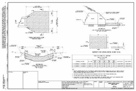
12 Bank and Channel Linings - Geotechnical Procedure GDP-10 Dumped stone Inlet Apron Geotechnical Procedure GDP-10 June 1995 SECOND EDITION GDP-10 Provides guidance on the selection of protective linings for stream banks and channels Apron sized by diameter of culvert Design to minimum stone blanket thickness or greater. STATE OF NEW YORK DEPARTMENT OF TRANSPORTATION Concrete and asphalt linings are not recommended. Extend height to calculated headwater depth. Culvert Outlet Protection Dumped Stone Outlet Protection Design


 also contains")


13 Culvert Outlet Protection GDP-10 Channel Lining Design Charts Culvert Outlet & Lining Protection Multiple Culvert Installation Standard Sheets & DEC NYS Standards and Specifications for Erosion and Sediment Control. (AKA The Blue Book ) also contains information for outlet and channel protection. Standard Installation Std. Sheet Installation with CLSM Std. Sheet See Section 5, Pg. 5B.21
 Min Max Min Max Conspan(arch) 12ft 48ft 3ft 13ft Hyspan (flat top) 6 ft 40 ft 2 ft 10 ft PC")
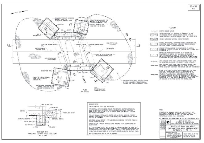
14 Safety & Protection Culvert End Sections Safety Culvert End Safety Grates NYSDOT end sections not hydraulically efficient Ke=0.7 STRUCTURAL LIMITATIONS Product Limitations Precast Concrete Span Rise* Structures Bottomless (3-sided) Min Max Min Max Conspan(arch) 12ft 48ft 3ft 13ft Hyspan (flat top) 6 ft 40 ft 2 ft 10 ft PC Arches (Bebo, 11 ft 60 ft 3.5 ft 22 ft Kistner, etc.) Box culvert (4-sided) 2 ft 20 ft 2 ft 10 ft STRUCTURAL LIMITATIONS 3 SIDED STRUCTURES Need scour protection Need piles driven to rock Piles increase construction time $$ Typically more expensive $$ *Minimum rises are limited by NYSDOT practice that designs have span-to-rise ratios of 4 or less. A larger ratio (greater span in relation to rise) increases moments in the top slab and foundation loads to the point where they are impractical/uneconomical to build. Maximum rise is limited by shipping constraints for Conspan, Hyspan and Box Culverts. Listed above are some of the more common manufacturers of precast 3 sided structures.
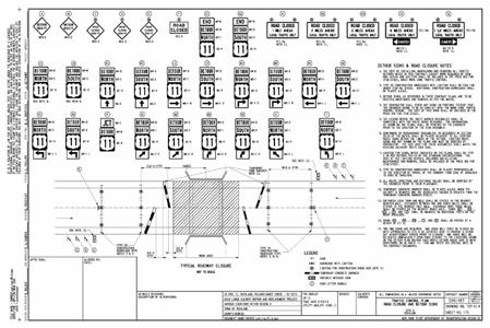
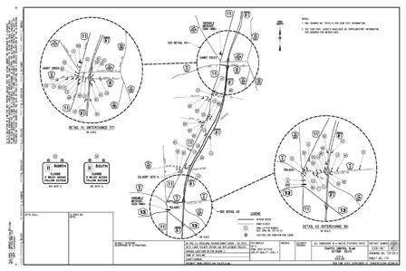
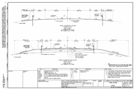
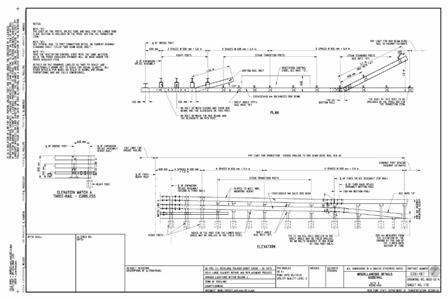
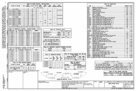
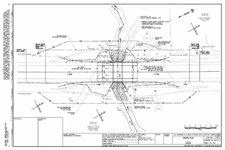
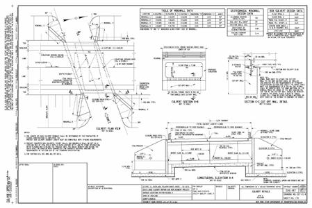
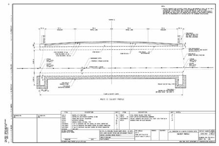
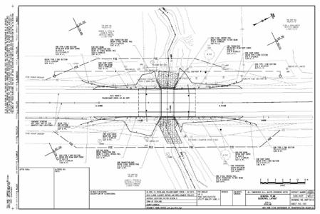
15 STRUCTURAL LIMITATIONS Span to Rise Ratio Longer span may increase rise Raise the highway profile Widen toe of slope $$ Increase culvert length $$ May also impact a greater amount of stream bed and any adjacent wetlands STRUCTURAL LIMITATIONS Fill Height Arched and round culverts handle large fills better As cover nears 10 ft and span approaches 20 ft, top slabs of box structures becomes excessively thick and impractical. Arch types should be used for fills over 10 ft. For other material fill limitations see HDM chapter 8, Appendix A PLAN SET Typical Sections (Culvert & Highway) Plan View Highway Profile (Existing & Proposed) Stream Profile Hydraulic Data Culvert and Wing Wall Elevations Staging Plan (if necessary) Guiderail Plans / Details
16
17

18
19


 Anti-seep collars Culvert Failures Undermining - Caused by")
20 Culvert Failures Seepage (Piping) Undermining Buoyancy Overtopping Blockage Materials Culvert Failures Seepage Caused from flow of water on exterior of pipe. Removes material, eventually leading to failure. Common on multiple pipe installations due to poor compaction between pipes. Prevention: Cut-off walls at inlet Proper compaction of material along barrel Proper materials used for backfill (not crushed stone) Anti-seep collars Culvert Failures Undermining - Caused by scour at the outlet, removing material upstream. Prevention: Use cut-off wall at outlet Proper outlet protection


21 Culvert Failures Buoyancy Caused by high water tables, with air being trapped in barrel of culvert. Typically causes lifting of culvert resulting in seepage. Common with CSP and Plastic pipes. Prevention: Proper barrel material selection. Design of culvert to prevent air entrapment in barrel Culvert Failures Overtopping Caused by water going over feature, eroding material from both upstream and downstream. Can be caused by inlet blockage. Prevention: Proper design of culvert for storm event. Review of watershed for debris potential. Culvert Failures Blockage Primarily debris accumulation on inlet, constricting flow and causing overtopping to occur. Can also be caused by end sections not being anchored. Culvert Failures Materials Caused by soil conditions reacting with pipe materials. Resulting in seepage and undermining. Prevention: Cut-off walls on end sections Review of watershed for debris potential Use of debris deflectors Prevention: Proper selection of culvert materials for project site.
 Open Channel Flow, FHWA Hydraulic Engineering Circular 22 (HEC 22) Culvert Design, FHWA Hydraulic Design Series No.")
22 Resources Highway Design Manual, Chapter 8 Open Channel Flow, FHWA Hydraulic Design Series No. 3 (HDS-3) Open Channel Flow, FHWA Hydraulic Engineering Circular 22 (HEC 22) Culvert Design, FHWA Hydraulic Design Series No. 5 (HDS-5) Culvert Design, NHI Course Questions? Peter Van Kampen MO Design Albany, NY pvankampen@dot.state.ny.us
CHAPTER 4 SPALDING COUNTY, GEORGIA 4.0 CULVERT DESIGN
 SPALDING COUNTY, GEORGIA CHAPTER 4 4.0 CULVERT DESIGN... 4-1 4.1 INTRODUCTION... 4-1 4.2 SYMBOLS AND DEFINITIONS... 4-1 4.3 ENGINEERING DESIGN CRITERIA... 4-2 4.3.1 FREQUENCY FLOOD... 4-2 4.3.2 VELOCITY
Indiana LTAP Road Scholar Core Course #10 Culvert Drainage. Presented by Thomas T. Burke, Jr., PhD, PE Christopher B. Burke Engineering, Ltd.
 Indiana LTAP Road Scholar Core Course #10 Culvert Drainage Presented by Thomas T. Burke, Jr., PhD, PE Christopher B. Burke Engineering, Ltd. Objectives Review culvert shapes, end sections, and materials
General Information for Culvert Design
 Design Manual Chapter 2 - Stormwater 2E - Culvert Design 2E-1 General Information for Culvert Design A. Introduction A culvert is a conduit under an embankment that transports stormwater from one side
CHAPTER 5 CULVERT DESIGN
 CHAPTER 5 CULVERT DESIGN HYDRAULICS OF CULVERTS There are two major types of culvert flow: 1) flow with inlet control, and 2) flow with outlet control. For each type, different factors and formulas are
The Basics of Culvert and Inlet Design
 PDHonline Course C619 (8 PDH) The Basics of Culvert and Inlet Design Jerry D. Morrow, PE 2013 PDH Online PDH Center 5272 Meadow Estates Drive Fairfax, VA 22030 6658 Phone & Fax: 703 988 0088 www.pdhonline.org
Culvert Design Basics
 PDHonline Course C287 (4 PDH) Culvert Design Basics Instructor: George E. Thomas, PE 2012 PDH Online PDH Center 5272 Meadow Estates Drive Fairfax, VA 22030-6658 Phone & Fax: 703-988-0088 www.pdhonline.org
Culvert Design for Low and High Gradient Streams in the Midwest. Dale Higgins, Hydrologist Chequamegon-Nicolet National Forest
 Culvert Design for Low and High Gradient Streams in the Midwest Dale Higgins, Hydrologist Chequamegon-Nicolet National Forest Overview Culvert Design Considerations Hydraulic Terms Culvert Impacts Low
Technical Report Culvert A Hydraulic Analysis
 DATE: November 3, 2011 Technical Report Culvert A Hydraulic Analysis TO: FROM: RE: Jim Reiser, P.E. Project Manager Parsons Brinckerhoff, Inc. Kurt Killian, P.E., CFM Parsons Brinckerhoff, Inc. Design
Storm Damage Floating Culverts & Other Inlet Issues
 Storm Damage Floating Culverts & Other Inlet Issues Mark Bailey, PE - Hydraulic Manager, INDOT Dale Sedler, PE - Sr. Hydraulic Engineer, INDOT Road School 2016 What causes a culvert to float? 1. Accumulation
HY-8 Version 7.2 Build Date January 17, Federal Highway Administration.
 HY-8 Version 7.2 Build Date January 17, 2012 Federal Highway Administration http://www.fhwa.dot.gov/engineering/hydraulics/software/hy8/index.cfm SIMPLE Simple to use Use for simple culverts and bridges
OFFICE OF STRUCTURES MANUAL FOR HYDROLOGIC AND HYDRAULIC DESIGN CHAPTER 13 CULVERTS APRIL 2011
 OFFICE OF STRUCTURES MANUAL FOR HYDROLOGIC AND HYDRAULIC DESIGN CHAPTER 13 CULVERTS APRIL 2011 APRIL 2011 Chapter 13 Culverts Table of Contents Foreword.3 13.1 Introduction.. 4 13.2 Policy 6 13.3 Passage
Chapter 11. Culverts and Bridges Design Checklist for Culvert Design
 Yes No N/A Design Requirements I. GENERAL DESIGN GUIDELINES Chapter 11. Culverts and Bridges A. Culvert design is in accordance with the Culverts chapter of Volume 2 of the UDFCD Manual for additional
APPENDIX B HYDRAULIC DESIGN DATA FOR CULVERTS
 TM 5-820-4/AFM 88-5, Chap 4 APPENDIX B HYDRAULIC DESIGN DATA FOR CULVERTS B-1. General. a. This appendix presents diagrams, charts, coefficients and related information useful in design of culverts. The
HEC 26 Aquatic Organism Passage Design Manual Evolution & Application
 HEC 26 Aquatic Organism Passage Design Manual Evolution & Application Sven Leon, P.E., Hydraulics Engineer Federal Highway Administration 2015 Alaska Fish Passage Meeting October 13 14, 2015 VTRC, Juneau,
(Revised February,2005) CULVERTS, BRIDGES, AND FORDS
 CULVERTS, BRIDGES, AND FORDS") GUIDE TO STREAM CROSSINGS (Revised February,2005) CULVERTS, BRIDGES, AND FORDS Culverts, bridges, and fords are all methods used to cross-streams. Culverts are the most common stream crossing structure.
GUIDE TO STREAM CROSSINGS (Revised February,2005) CULVERTS, BRIDGES, AND FORDS Culverts, bridges, and fords are all methods used to cross-streams. Culverts are the most common stream crossing structure.
APPENDIX C VEGETATED EMERGENCY SPILLWAY. VERSION 1.0 March 1, 2011
 APPENDIX C VEGETATED EMERGENCY SPILLWAY VERSION 1.0 March 1, 2011 [NOTE: Could use a better photo more clearly showing the emergency spillway in the context of the dam.] SECTION C-1: DESCRIPTION OF PRACTICE
APPENDIX J HYDROLOGY AND WATER QUALITY
 APPENDIX J HYDROLOGY AND WATER QUALITY J-1 Technical Report on Airport Drainage, Northern Sector Airport and Ordinance Creek Watershed / Preliminary Creek Constructed Natural Channel Culvert J-2 Preliminary
Presented by Fred Halterman, URS Jennie Agerton, URS
 Presented by Fred Halterman, URS Jennie Agerton, URS What is Eco Friendly Culvert Design? Culvert design that: Maintains connectivity for aquatic organism migration Maintains connectivity for gene flow
APPENDIX C ESTIMATING SCOUR IN BOTTOMLESS ARCH CULVERTS
 OFFICE OF STRUCTURES MANUAL FOR HYDROLOGIC AND HYDRAULIC DESIGN CHAPTER 11, EVALUATING SCOUR AT BRIDGES APPENDIX C ESTIMATING SCOUR IN BOTTOMLESS ARCH CULVERTS APRIL 2011 APPENDIX C ESTIMATING SCOUR IN
WMS 8.4 Tutorial Hydraulics and Floodplain Modeling HY-8 Modeling Wizard Learn how to model a culvert using HY-8 and WMS
 v. 8.4 WMS 8.4 Tutorial Hydraulics and Floodplain Modeling HY-8 Modeling Wizard Learn how to model a culvert using HY-8 and WMS Objectives Define a conceptual schematic of the roadway, invert, and downstream
Sediment Basin 7E-12. Design Manual Chapter 7 - Erosion and Sediment Control 7E - Design Information for ESC Measures BENEFITS.
 7E-12 Design Manual Chapter 7 - Erosion and Sediment Control 7E - Design Information for ESC Measures Sediment Basin BENEFITS Flow Control Erosion Control Sediment Control Runoff Reduction Flow Diversion
OFFICE OF STRUCTURES MANUAL FOR HYDROLOGIC AND HYDRAULIC DESIGN CHAPTER 11 APPENDIX B TIDEROUT 2 USERS MANUAL
 OFFICE OF STRUCTURES MANUAL FOR HYDROLOGIC AND HYDRAULIC DESIGN CHAPTER 11 APPENDIX B TIDEROUT 2 USERS MANUAL APRIL 2011 APRIL 2011 Page 1 Preface TIDEROUT 2, Build 1.22 dated June 29, 2006 is the current
Annex E Bridge Pier Protection Plan
 Annex E Bridge Pier Protection Plan Table E1 Bridge Types and Locations Table E2 Flow Conditions For River Sections Figure E1 Bridge Abutment Protection Figure E2 Bridge Pier Protection Figure E3 Central
BC Ministry of Forests. March Fish Stream Crossing Guidebook. Forest Practices Code of British Columbia.
 FRST 557 Lecture 7c Bridges and Culverts: Water Velocity and Discharge Lesson Background and Overview: The previous two lessons presented methods for estimating water volume flow at a particular site and
USING A LABYRINTH WEIR TO INCREASE HYDRAULIC CAPACITY. Dustin Mortensen, P.E. 1 Jake Eckersley, P.E. 1
 USING A LABYRINTH WEIR TO INCREASE HYDRAULIC CAPACITY Dustin Mortensen, P.E. 1 Jake Eckersley, P.E. 1 Plum Creek Floodwater Retarding Structure No. 6 is located in an area of Kyle, Texas, that is currently
Aquatic Organism Passage at Road-Stream Crossings CHUCK KEEPORTS FOREST HYDROLOGIST ALLEGHENY NATIONAL FOREST WARREN, PENNSYLVANIA
 Aquatic Organism Passage at Road-Stream Crossings CHUCK KEEPORTS FOREST HYDROLOGIST ALLEGHENY NATIONAL FOREST WARREN, PENNSYLVANIA TOPICS COVERED Aquatic Organism Passage (AOP) Benefits of AOP Crossings
Summary of HEC 18, Evaluating Scour at Bridges FHWA NHI Should really follow HEC 18, but this summary will get you the main points.
 Summary of HEC 18, Evaluating Scour at Bridges FHWA NHI 01-001 Should really follow HEC 18, but this summary will get you the main points. 1: Determine scour analysis variables 2: Analyze long-term bed
MEMORANDUM. TNC Fisher Slough Final Design and Permitting Subject: DRAFT Technical Memorandum: Levee Emergency Spillway Design
 MEMORANUM TNC Fisher Slough Final esign and Permitting Subject: RAFT Technical Memorandum: Levee Emergency Spillway esign To: From: Internal Memorandum For Record Yen Hsu Chen (Tetra Tech) avid Cline (Tetra
Components of a Barrage
 Components of a Barrage Definition The only difference between a weir and a barrage is of gates, that is the flow in barrage is regulated by gates and that in weirs, by its crest height. Barrages are costlier
Great Lakes Stream Crossing Inventory Instructions
 Great Lakes Stream Crossing Inventory Instructions This document is a guide to completing the Stream Crossing Data Sheet (2/28/11 version). Careful attention to this guidance will ensure consistent crossing
Culvert Hydraulics: Comparison of Current Computer Models
 Brigham Young University BYU ScholarsArchive All Theses and Dissertations 2007-03-13 Culvert Hydraulics: Comparison of Current Computer Models Elizabeth Anne Thiele Brigham Young University - Provo Follow
REVETMENTS. Purposes and Operational Constraints. Purposes Erosion control o o. Revetment Design 4/5/2016. CE A676 Coastal Engineering
 REVETMENTS Ijsseldam, the Netherlands Orson P. Smith, PE, Ph.D. Instructor Purposes and Operational Constraints Purposes Erosion control o o Embankment Toe protection for a seawall, retaining wall or other
Rock Ramp Design Guidelines. David Mooney MS Chris Holmquist-Johnson MS Drew Baird Ph.D. P.E. Kent Collins P.E.
 Rock Ramp Design Guidelines David Mooney MS Chris Holmquist-Johnson MS Drew Baird Ph.D. P.E. Kent Collins P.E. Rock Ramp Design Guidelines OUTLINE Local and System Interactions with Rock Ramps Ramp Geometry
FINAL REPORT. Yonkers Creek Migration Barrier Removal Project Wonderstump Road Del Norte County. Submitted By:
 FINAL REPORT Yonkers Creek Migration Barrier Removal Project Wonderstump Road Del Norte County Submitted By: Del Norte County Community Development Department Yonkers Creek Migration Barrier Removal Project
HYDROLOGIC AND HYDRAULIC REPORT PROPOSED CULVERT STRUCTURES SR 194, SECTION 10
 HYDROLOGIC AND HYDRAULIC REPORT PROPOSED CULVERT STRUCTURES SR 194, SECTION 10 RACETRACK ROAD CULVERT OVER THE SPRING RUN & GREEN SPRINGS ROAD CULVERT OVER AN UNNAMED TRIBUTARY TO SPRING RUN BERWICK TOWNSHIP
Bridge Failures in Alberta
 Introduction Bridge Failures in Alberta Bridges are inspected for three primary reasons safety of bridge system maintenance of bridges management of bridge system Inventory or management of the system
Fish Passage Assessment Report Mare Brook Culverts
 Fish Passage Assessment Report Mare Brook Culverts Fish Passage Assessment Component of Mare Brook Watershed Assessment and Community Engagement Project Prepared for: FB Environmental Associates 97A Exchange
Session 1. Pushover Analysis of a Torsionally Eccentric Cellular Abutment. Date 11/03/ PM 4 PM Eastern Time
 Session 1 Pushover Analysis of a Torsionally Eccentric Cellular Abutment Date 11/03/2016 3 PM 4 PM Eastern Time Today s Presenter: Jon Emenheiser, PE Copyright Materials This presentation is protected
Modeling of Long Culverts and Stormdrains A Comparison of Different Methods
 Modeling of Long Culverts and Stormdrains A Comparison of Different Methods Shrinivas Kaulgud, P.E., CFM Cheryl Hannan, P.E., CFM, LEED AP October 12, 2017 Presentation Outline Introduction Case Studies
Driveway Design Criteria
 Design Manual Chapter 5 - Roadway Design 5L - Access Management 5L-4 Driveway Design Criteria A. General For efficient and safe operations, access drives and minor public street intersections can be improved
Chutes Part 2: Synthetic linings
 s Part 2: Synthetic linings DRAINAGE CONTROL TECHNIQUE Low Gradient Velocity Control Short Term Steep Gradient Channel Lining Medium-Long Term Outlet Control [1] Soil Treatment Permanent [2] [1] s can
Stephens Creek Culvert Replacement. CAC April 28, 2010
 Stephens Creek Culvert Replacement CAC April 28, 2010 1 Top of Bank Willamette Moorage Park Existing Culverts 50 ft Greenway Setback 200 ft Greenway Setback Existing Macadam Bay Access Stephens Creek Existing
Outlet Structures T-12
 Description This section provides guidance and details for outlet structures for use primarily with BMPs utilizing sedimentation, (i.e., extended detention basins (EDBs), retention ponds, and constructed
Massachusetts Stream Crossing Case Studies
 Massachusetts Stream Crossing Case Studies Amy Singler Associate Director, River Restoration Program Carrie Banks River Continuity Coordinator Case Studies: Public Benefits: Movement of goods and people
MEMO. Schedule 'B' Class Environmental Assessment and Preliminary Design Lakeview Boulevard Improvements Culvert Assessment.
 MEMO Schedule 'B' Class Environmental Assessment and Preliminary Design Lakeview Boulevard Improvements Culvert Assessment February 15, 2017 As per the preferred Lakeview Boulevard alignment provided by
SELBY CREEK SILVERADO TRAIL CULVERT FISH PASSAGE ASSESSMENT
 SELBY CREEK SILVERADO TRAIL CULVERT FISH PASSAGE ASSESSMENT NAPA COUNTY, CALIFORNIA PREPARED BY NAPA COUNTY RESOURCE CONSERVATION DISTRICT 1303 JEFFERSON ST. SUITE 500B NAPA, CALIFORNIA 94559 WWW.NAPARCD.ORG
UNDERWATER BRIDGE INSPECTION REPORT STRUCTURE NO CSAH 133 OVER A DITCH ST. LOUIS COUNTY
 UNDERWATER BRIDGE INSPECTION REPORT STRUCTURE NO. 7780 CSAH 133 OVER A DITCH ST. LOUIS COUNTY SEPTEMBER 27, 2012 PREPARED FOR THE MINNESOTA DEPARTMENT OF TRANSPORTATION BY COLLINS ENGINEERS, INC. JOB NO.
Access Management Standards
 Access Management Standards Section 1: Application of Access Standards This chapter describes the Department's access management standards for access connections on the county roadway system. The standards
Memorandum. Dr. Wilbert Odem, Dr. Paul Trotta, and Mr. Justin Ramsey. From: Timothy Mahon, Patrick Belsheim, and Ali Alrayyes.
 Memorandum To: Dr. Wilbert Odem, Dr. Paul Trotta, and Mr. Justin Ramsey From: Timothy Mahon, Patrick Belsheim, and Ali Alrayyes Date: 10/17/2013 Re: Routes Decision Matrix Decision Matrix Methodology The
CALIFORNIA SALMONID STREAM HABITAT RESTORATION MANUAL APPENDIX IX-A CULVERT CRITERIA FOR FISH PASSAGE INTRODUCTION
 APPENDIX IX-A STATE OF CALIFORNIA RESOURCES AGENCY DEPARTMENT OF FISH AND GAME CULVERT CRITERIA FOR FISH PASSAGE For habitat protection, ecological connectivity should be a goal of stream-road crossing
Washington State Fish Passage Barrier Removal Projects. Casey Kramer, PE WSDOT State Hydraulics Engineer
 Washington State Fish Passage Barrier Removal Projects Casey Kramer, PE WSDOT State Hydraulics Engineer 2014 National Hydraulic Engineering Conference Iowa City, IA August 20 th, 2014 WSDOT Fish Passage
Fish Passage Assessment of Private Stream Crossings on Lower Stonybrook Creek
 Fish Passage Assessment of Private Stream Crossings on Lower Stonybrook Creek Prepared by: Michael Love & Associates In cooperation with: Center for Ecosystem Management and Restoration Funded by: Coastal
TECHNICAL MEMORANDUM 002 EMORANNO. 001
 TECHNICAL MEMORANDUM 002 EMORANNO. 001 To: Jack Synder, P.E. EES Consulting From: Mort McMillen, P.E. Paul Larson, SE Date: October 13, 2010 Project: Cc: Taylor Bowen Subject: Technical Memorandum (TM)
Appendix G. Alternative Solutions Details. Krosno Creek Flood Reduction Project PROJECT FILE REPORT CITY OF PICKERING
 Krosno Creek Flood Reduction Project PROJECT FILE REPORT CITY OF PICKERING Appendix G Alternative Solutions Details TMIG THE MUNICIPAL INFRASTRUCTURE GROUP LTD Krosno Creek Flood Reduction Project PROJECT
Design & Maintenance of Culverts
 While every effort is made to ensure that information held within this document is accurate and up to date, Croft Consultants will not be held responsible for any loss, damage, injury, or inconvenience
UNDERWATER BRIDGE INSPECTION REPORT STRUCTURE NO CSAH 4 OVER THE BEAVER RIVER ST. LOUIS COUNTY
 UNDERWATER BRIDGE INSPECTION REPORT STRUCTURE NO. 7635 CSAH 4 OVER THE BEAVER RIVER ST. LOUIS COUNTY JUNE 18, 2012 PREPARED FOR THE MINNESOTA DEPARTMENT OF TRANSPORTATION BY COLLINS ENGINEERS, INC. JOB
STRUCTURE S-65 PURPOSE SPILLWAY OPERATION
 STRUCTURE S-65 This structure is a reinforced concrete, gated spillway with discharge controlled by three cable operated, vertical lift gates, and a reinforced concrete lock structure with two pairs of
Little Traverse Bay Watershed Road/Stream Crossing Inventory
 Little Traverse Bay Watershed Road/Stream Crossing Inventory Completed by Tip of the Mitt Watershed Council with support from: Petoskey-Harbor Springs Area Community Foundation s Little Traverse Bay Protection
Plan B Dam Breach Assessment
 Plan B Dam Breach Assessment Introduction In support of the Local Sponsor permit applications to the states of Minnesota and North Dakota, a dam breach analysis for the Plan B alignment of the Fargo-Moorhead
APPENDIX A STRUCTURE DESCRIPTIONS AND RATING CURVES
 3 4 5 6 7 8 9 0 3 APPENDIX A STRUCTURE DESCRIPTIONS AND RATING CURVES Kissimmee River Vol December 005 Version Draft 4 3 4 5 6 7 8 9 0 3 4 5 6 7 8 9 0 3 4 5 6 7 8 9 30 3 3 33 34 35 36 37 38 39 40 4 4 43
DUAL-VORTEX SEPARATOR. Inspection and Maintenance Guide
 DUAL-VORTEX SEPARATOR Inspection and Maintenance Guide Description The Dual-Vortex Separator (DVS) is a hydrodynamic stormwater treatment device used to remove pollutants from urban runoff. Impervious
APPENDIX C. Fluvial and Tidal Hydraulics Report
 APPENDIX C Fluvial and Tidal Hydraulics Report BUENA VISTA LAGOON ENHANCEMENT PROJECT FLUVIAL AND TIDAL HYDRAULICS ANALYSES Prepared for: SANDAG 401 B Street, Suite 800 San Diego, California 92101 Contact:
Project Report for Marsh Creek and Albion River Instream Fish Barrier Removal Flynn Creek Road, CR 135, M.P. 8.1 and 8.3
 Project Report for Marsh Creek and Albion River Instream Fish Barrier Removal Flynn Creek Road, CR 135, M.P. 8.1 and 8.3 Project Title: Marsh Creek and Albion River Instream Fish Barrier Removal, Flynn
Earthen Embankments. turning into larger, more costly repairs. The following. The State Dam Safety Program has inspection
 TOPIC: COMMON PROBLEMS FOR SMALL DAMS WITH CONCRETE CHANNEL SPILLWAYS The State Dam Safety Program has inspection requirements for state regulated dams. A dam, like any man-made structure, will change
Suitable Applications Check dams may be appropriate in the following situations: To promote sedimentation behind the dam.
 Categories EC Erosion Control SE Sediment Control TC Tracking Control WE Wind Erosion Control Non-Stormwater NS Management Control Waste Management and WM Materials Pollution Control Legend: Primary Category
Bids DECEMBER 21, 2018 AT 2:00 P.M. (EASTERN) (Estimated Cost: $4,700,000.00)
 (Estimated Cost: $4,700,000.00)") General Info Number: PROJECT NO. 43-19-03 Description: BRIDGE DECK REPAIR AND REHABILITATION OHIO TURNPIKE RAMP OVER STATE ROUTE 420 M.P. 71.4, SOUTH BILLMAN ROAD OVER OHIO TURNPIKE M.P. 75.2, WOOD AND
General Info Number: PROJECT NO. 43-19-03 Description: BRIDGE DECK REPAIR AND REHABILITATION OHIO TURNPIKE RAMP OVER STATE ROUTE 420 M.P. 71.4, SOUTH BILLMAN ROAD OVER OHIO TURNPIKE M.P. 75.2, WOOD AND
Lecture 10 : Sewer Appurtenances
 1 P age Module 8 : Sewer Appurtenances Lecture 10 : Sewer Appurtenances 2 P age The structures, which are constructed at suitable intervals along the sewerage system to help its efficient operation and
ADDENDA B Hydrologic and Hydraulic (H&H) Study Guidance 2019
 Study Guidance 2019") 09/25/2018 DRAFT FEMA Region I PA H&H Study ADDENDA B Hydrologic and Hydraulic (H&H) Study Guidance 2019 Region I Federal Emergency Management Agency (FEMA) Public Assistance Hydrologic and Hydraulic (H&H)
09/25/2018 DRAFT FEMA Region I PA H&H Study ADDENDA B Hydrologic and Hydraulic (H&H) Study Guidance 2019 Region I Federal Emergency Management Agency (FEMA) Public Assistance Hydrologic and Hydraulic (H&H)
STRUCTURE 65-B PURPOSE SPILLWAY OPERATION
 STRUCTURE 65-B This structure is a reinforced concrete, gated spillway with discharge controlled by three cable operated vertical lift gates and a reinforced concrete lock structure with two pairs of sector
Assessment of Baseline Geomorphic Features at. Proposed Stream Crossings On The Proposed County Road 595. Marquette County, Michigan
 Assessment of Baseline Geomorphic Features at Proposed Stream Crossings On The Proposed County Road 595 Marquette County, Michigan Prepared for: Kennecott Eagle Minerals Company Marquette, Michigan Prepared
Joe Rathbun Michigan DEQ Water Resources Division Nonpoint Source Unit * Thanks to The Nature Conservancy
 Joe Rathbun Michigan DEQ Water Resources Division Nonpoint Source Unit rathbunj@mi.gov * Thanks to The Nature Conservancy Road-stream intersections = 67,511 Culverts = 60,700 Bridges = 6,811 Perched Piping
Design Data 22M. Flotation of Circular Concrete Pipe. w w I = w - x 1000 (3) (SG x 1000)
 (SG x 1000)") Design Data M Flotation of Circular Concrete Pipe There are several installation conditions where there is the possibility that concrete pipe may float even though the density of concrete is approximately.4
Design Data M Flotation of Circular Concrete Pipe There are several installation conditions where there is the possibility that concrete pipe may float even though the density of concrete is approximately.4
Section 10 - Hydraulic Analysis
 Section 10 - Hydraulic Analysis Methodology Documentation Functionality Summary Sizing Methodology Fixed/Resize Combined Flow Storm: Sizing as per d/d Structures.dat Storm vs. Sanitary Methodology HGL/EGL
PERKFILTER. Inspection and Maintenance Guide
 PERKFILTER Inspection and Maintenance Guide PerkFilter Media Filtration System Description The PerkFilter is a stormwater treatment device used to remove pollutants from urban runoff. Impervious surfaces
Fish Friendly Crossings- Examples from Nash Stream
 Fish Friendly Crossings- Examples from Nash Stream Maggie Machinist- North Regional Forester, Division of Forests and Lands. Nash Stream Nash Stream Forest is 40,000 acres, owned and managed by NH Division
2D Modelling Series. Modelling Structures in Floodplains
 2D Modelling Series Modelling Structures in Floodplains Jessica Jefferys Products Manager XP Solutions XP-LIVE Webinars XP-LIVE educational program Webinars have been recorded and are available at http://www.xpsolutions.com/
Minimum Standards for Driveway Construction Village of Bear Creek
 Minimum Standards for Driveway Construction Village of Bear Creek An exception to the following requirements may only be granted by city council. The needs of each drainage system are considered independently,
Vermont. Vermont Fish & Wildlife Department 1 National Life Drive Montpelier, VT
 Vermont Stream Crossing Vermont Fish & Wildlife Department 1 National Life Drive Montpelier, VT 05620-3702 802-828-1000 www.vtfishandwildlife.com Handbook Introduction Vermonters have always strongly connected
CLEANING, INSPECTION, AND TESTING OF SEWERS
 CLEANING, INSPECTION, AND TESTING OF SEWERS PART 1 - GENERAL 1.01 SECTION INCLUDES A. Cleaning, Inspecting, and Testing Sanitary Sewers B. Cleaning, Inspecting, and Testing Storm Sewers C. Cleaning and
Simulating Streams Through Culverts in Mat-Su, Alaska
 Simulating Streams Through Culverts in Mat-Su, Alaska Project Managers Bill Rice, P.E., USFWS Hydrologist Mary Price, USFWS Fishery Biologist The Team Approach US Fish and Wildlife Service Bill Rice, P.E.,
MITIGATING PIPE AND RISER HYDRAULIC PIPELINE ISSUES WITH THE I-RISER PLUS
 24 TH July 2013 MITIGATING PIPE AND RISER HYDRAULIC PIPELINE ISSUES WITH THE I-RISER PLUS Vern Costelow Business Development Consultant AWMA Water Control Solutions INTRODUCTION Surface irrigation is still
Request Number IR1-12: Flow Passage. Information Request
 Request Number IR1-12: Flow Passage Information Request Provide additional information about the 100 metre flow passage channel scenario between the Westshore Terminals and the proposed Project terminal
TOP:001.3 U.S. Fish and Wildlife Service TECHNICAL OPERATING PROCEDURE
 TOP:001.3 March 12, 2015 U.S. Fish and Wildlife Service Marquette Biological Station 3090 Wright Street Marquette, Michigan 49855 U.S.A. and U.S. Fish and Wildlife Service Ludington Biological Station
City of Guelph. Hanlon Creek Business Park Stormwater Management Report Ponds 1, 2, 3 and 4
 City of Guelph Hanlon Creek Business Park Stormwater Management Report Ponds 1, 2, 3 and 4 City of Guelph Hanlon Creek Business Park Stormwater Management Report Ponds 1, 2, 3 and 4 Prepared by: AECOM
Bridge Design Preliminary Bridge Design Example 1 / 6 Spring 2012 updated 1/27/2012
 Bridge Design Preliminary Bridge Design Example 1 / 6 Perform a preliminary design for a bridge on a state highway over a large creek in rural Alabama. Produce a construction layout drawing showing profile
 Dam Modification Report Stingy Run Fly Ash Reservoir Appendix E Spillway System Design Calculations E1: Spillway/Energy Dissipater Design for 100-year Event CHE8273 8 September 4, 2014 Written by: CJW
Added Introduction: Comparing highway design and stream design
 Added Introduction: Comparing highway design and stream design Highway width is sized for the traffic, the width expanding as volume and speed increase. The ROW width is also designed to handle the speed
Illinois State Water Survey
 Illinois State Water Survey HYDROLOGY DIVISION SWS Contract Report 508 COMPARISON OF 1987 AND 1989 BED PROFILE SURVEYS OF THE LOWER CACHE RIVER by Richard Allgire Office of Sediment and Wetland Studies
CE 535, Spring 2002 Preliminary Design Example 1 / 6
 CE 535, Spring 2002 Preliminary Design Example 1 / 6 Perform a preliminary design for a bridge on a state highway over a large creek in rural Alabama. Produce a construction layout drawing showing profile
Stream Crossings I: Engineering and Design Approaches to Provide Fish Passage at Culvert Slipline Projects in Connecticut
 University of Massachusetts - Amherst ScholarWorks@UMass Amherst International Conference on Engineering and Ecohydrology for Fish Passage International Conference on Engineering and Ecohydrology for Fish
Chadbourne Dam Repair and Fish Barrier
 Chadbourne Dam Repair and Fish Barrier Final Report for the Western Native Trout Initiative Prepared by: Carol Endicott Yellowstone Cutthroat Trout Conservation Biologist Montana Fish, Wildlife & Parks
2010 STANDARD SPECIFICATIONS STANDARD DRAWINGS
 CITY OF REDMOND, OREGON 2010 STANDARD SPECIFICATIONS STANDARD DRAWINGS TABLE OF CONTENTS SECTION 1 TRENCHES TITLE 1-1 Utility Trench 1-2 Water Line & Sewer Line Separation 1-3 RR X-ING Single/Joint Use
Access requests to County streets and roadways are processed through one of the following methods:
 13.1 GENERAL APPLICATION PROCESS Access requests to County streets and roadways are processed through one of the following methods: A. Planned Developments may set general locations for access points.
City of Roseville Section 13 Design Standards. _Bikeways January 2016 SECTION 13 BIKEWAYS
 SECTION 13 BIKEWAYS 13-1 GENERAL The City of Roseville bikeway standards are designed to insure that transportation and recreational bikeways are constructed in a manner that would provide a safe and comfortable
If you have comments on this or suggestions for other terms that should be added to this glossary, please send an to
 Tide Gates Glossary There is very little information available anywhere related to tide gates and flap gates. This is a glossary of terms that are associated with, or useful when discussing, tide gates.
As temporary grade control facilities along waterways until final stabilization is established.
 Check Dams (CD) EC-12 Description Check dams are temporary grade control structures placed in drainage channels to limit the erosivity of stormwater by reducing flow velocity. Check dams are typically
Stormwater Management Pond Design Brief. Greely Village Centre - Commercial Phase - Ultimate Conditions - - City of Ottawa -
 Stormwater Management Pond Design Brief Greely Village Centre - Commercial Phase - Ultimate Conditions - - City of Ottawa - December 2008 Ref: 647-07 J.F. Sabourin and Associates Inc. Water Resources and
Fish Passage Planning and Design
 Fish Passage Planning and Design Culvert Fishway Planning and Design Guidelines Part C Fish Migration Barriers and Fish Passage Options for Road Crossings Ross Kapitzke James Cook University School of
UNDERWATER BRIDGE INSPECTION REPORT METRO DISTRICT - ANOKA COUNTY
 UNDERWATER BRIDGE INSPECTION REPORT STRUCTURE NO. 02545 CR NO. 116 OVER THE RUM RIVER METRO DISTRICT - ANOKA COUNTY SEPTEMBER 9, 2012 PREPARED FOR THE MINNESOTA DEPARTMENT OF TRANSPORTATION BY COLLINS
Item 404 Driving Piling
 Item Driving Piling 1. DESCRIPTION Drive piling. 2. EQUIPMENT 2.1. Driving Equipment. Use power hammers for driving piling with specified bearing resistance. Use power hammers that comply with Table 1.