Shocker Sport TM Manual. Includes: Shocker Sport 4X4 TM and Shocker Sport Turbo TM
|
|
|
- Holly Horton
- 6 years ago
- Views:
Transcription

1 Shocker Sport TM Manual Includes: Shocker Sport 4X4 TM and Shocker Sport Turbo TM
2 WARNING! The Shocker Sport TM Paintball Marker is not a toy. Misuse or careless use may cause serious injury or death. The user and any person within range must wear eye protection designed for paintball use. Recommended at least 18 years old to purchase, 14 years old to use with adult supervision, or 10 years old to use on paintball fields meeting ASTM standard F Read operation manual before using. Always use barrel plugs when not involved in actual play. When gassing and de-gassing the marker s system, never aim the gun at another person. Always point the barrel towards the ground. Never use over-filled CO 2 bottles as this will spike the system causing the hoses to burst. Shocker Sport Limited Warranty Smart Parts warrants for 1 year to initial retail purchaser that the Shocker Sport paintball marker and regulator are free from defects in materials and workmanship. Disposable parts (batteries, o-rings, seals, etc) are not warranted. The fill poppet and firing piston are warranted for six months. The solenoids and electronics on your Shocker Sport are unconditionally warranted for six months, plus an additional warranty of six months for electronic parts only (installation and labor are not included.) This warranty does not cover surface damages (scratches and nicks,) misuse, or improper disassembly and re-assembly, or attempts made to drill holes or remove metal from the external surfaces, which could result in degrading the performance and reducing pressure safety factors. Do not use Teflon tape on any part of this marker--the tape can break off and plug the solenoids. Instead, use Loctite 271. Do not make changes to the basic marker parts without written approval. The only authorized lubricant for the gun is DOW 33 Lubricant. Use of any other lubricant could result in voiding your warranty. Use only those on/off switches purchased from Smart Parts. Unauthorized on/off switches will void this warranty. This warranty is limited to repair or replacement of defective parts with the customers to pay shipping costs. This warranty is effective only if the customer returns the warranty registration card enclosed with the marker. Thank you for purchasing the Shocker Sport. The Shocker Sport is the culmination of years of research and testing. Engineers at Smart Parts, building on their experience with the original Shocker, have given the Shocker Sport a complete overhaul to keep up with the demands of today s players and the quality you expect from Smart Parts, Inc. We ve made the Shocker Sport smaller, lighter and faster than the original Shocker while keeping the low pressure, accuracy and extremely low ball breakage! In addition, we ve upgraded the electronics, wiring and grounding to make the marker more reliable. The Shocker Sport now incorporates a digital circuit board, redesigned bolt assembly, new solenoid valves and an optional integrated air assist port. 2
3 THE BASICS The Shocker Sport 4x4 and Turbo consist of three main assemblies: the Body, the Solenoid Housing, and the Grip Frame. Body The Body is two interlinked systems, the Bolt and the Firing System. It also includes an air transfer port and air assist fitting port. The Bolt is contained in the upper chamber and should only be removed when the gun is degassed. The Bolt is operated by the rearmost solenoid controlling the air going to the front and rear of the bolt piston in order to make it travel back and forth. The bolt s function is to load the paintballs into the breach of the gun and to transfer the air from the firing system to the ball in order to propel it. The firing system contains three main moving parts: the firing piston, the fire rod and the fill poppet. The firing system is controlled by the foremost solenoid valve which when activated starts the firing cycle. The firing piston and fill poppet are contained in their respective housings. NOTE: The firing piston also contains a glide ring that is split to facilitate assembly. The air transfer port distributes air to the entire gun and has 1/8" N.P.T. ports at the front and rear of the gun. This also contains a gun filter. Clean the filter every six (6) months with alcohol. The air assist fitting port is where the air fitting is screwed into for the optional air assist elbow. It is located on the right-hand side of the gun. Solenoid Housing The solenoid housing serves three functions. First it encloses and protects the solenoids, secondly it holds the circuit board and third it connects the body and the grip frame. The solenoid housing is held to the body using four Phillips head cap screws. It is important not to over tighten these screws as thread damage may occur. The circuit board is mounted to the solenoid housing using screws and should not be removed or adjusted. The circuit board is coated with a water-repellent coating to prevent problems in wet playing conditions. The timing of the gun is preset at the factory. A small green LED is located on the side of the solenoid housing. This is the battery life indicator. It will light up continuously when the battery needs replaced. In front of the LED light is the on/off battery switch. This switch acts as the gun s safety. If you have purchased a Shocker Sport Turbo, your solenoid housing will have a 3-way switch protruding from the front of it. This is the Selective Mode switch. It allows you to select between Semi-Automatic and Turbo. With the switch in the center position the gun is in Semi- Automatic mode, the gun shoots once per trigger pull. Moving the switch to the left or right position when you are facing the back of the gun sets Turbo mode. Two switch covers are provided with the Shocker Sport, the tournament cover does not allow the modes to be changed during play. The recreational cap is exposes the switch to allow changing modes during play. Grip Frame The Grip Frame contains the trigger and battery. It is held to the solenoid housing with two 1/4"-20 screws. The front screw can be replaced with a 1/4"-20 stud and a handle. The batteries are replaceable and can be purchased through Smart Parts or any Smart Parts Authorized dealers. NOTE: It is highly recommended that you turn off your on/off switch after each day of play. This will greatly extend the life of the battery if you do not turn off your battery the power will slowly drain. With normal care and usage the batteries should last at least 100,000 shots. There are holes on the bottom of the grip frame for a standard bottomline fitting.
4 General Cleaning and Lubrication The body of the gun should be cleaned off with a damp cloth. In the unlikely event of a ball break, the bolt can be removed when the gun is degassed and a squeegee can be run through the entire upper chamber to clean out the paint residue. DO NOT run the gun under water to clean out broken paint. If you should ever lose or damage an o-ring or seal in your Shocker or your Shocker regulator you may purchase o-ring kits from Smart Parts. They are available in partial and complete kits for both the Shocker regulator and the Shocker. Your Shocker will need to be disassembled and re-lubricated with a LIGHT coat of Dow Corning 33 silicon grease after each day of play! The main parts that need greased are the bolt, the firing piston and the fill poppet. Proper lubrication is vital to the performance of your Shocker. If it is not lubricated thoroughly it will not perform at its optimum level! This may also result in premature failure of the o-rings. To lubricate the bolt you must unscrew it from the gun. Then using your finger work a small amount of grease into the holes in the body of the bolt, onto the bolt shaft and on the O-rings around the outside of the bolt cylinder body. After this is done work the bolt head back and forth to distribute the grease throughout the assembly. To lubricate the firing piston (10), first remove the firing cylinder (9) from the gun using a large flat headed screwdriver. (Note: The firing cylinder is located underneath the barrel on the front of the gun.) Next using a small pair of needle nosed pliers remove the firing piston from the firing cylinder. After it is removed spread a light coating of grease on all the o-rings and on the firing piston guide (11). After this is done replace the firing piston and the firing cylinder. To lubricate the fill poppet (13) first remove the fill poppet seat (12) from the rear of the gun using an adjustable wrench. The fill poppet seat is located below the bolt. Once the seat is removed you must remove the fill poppet guide (14) using a flat bladed screwdriver while holding the housing with an adjustable wrench. Once the cap is removed you should see the end of the fill poppet and the fill poppet bearing (19). Remove these items with a pair of needle nosed pliers. Once you have removed the poppet, spread a light coating of grease on the poppet and the poppet bearing and reassemble the poppet housing. Finally reinstall the poppet housing into the gun. Anti-siphon Information An anti-siphon tube is a tube that is installed in a CO 2 tank s valve in order to help prevent liquid CO 2 from entering the system. The tube is screwed into the back of the valve and bent so that the end of the tube will be pointing up when the tank is screwed into the gun. When the valve is completely screwed into the gun mark an X on the outside of the valve (or on the outside of the tank) near the neck to indicate the up position of the tube inside the tank and to also show that the tank is an Anti-Siphon Tank. NOTE: Tanks with anti-siphon tubes should only be used on the cradle or fitting that it was set-up for. If you use an anti-siphon tank on a different bottle adapter, there is a good possibility that the tube will be oriented incorrectly and draw liquid CO 2. Anti-siphon equipped tanks should never be used on remote systems. Anti-siphon tubes should only be installed by QUALIFIED AIRSMITHS. Please do not attempt to install an anti-siphon tube on your tank, have a professional install it for you. If you need more information regarding this matter please feel free to contact your local paintball field or Smart Parts at (724)
5 Battery Pack Removal and Replacement The battery pack is located in the grip frame and can be replaced easily. In order to change the battery pack one side of the grip must be removed. To do this you must use a Phillips head screwdriver and remove the two screws in the side of the grip frame holding the grip on. Once this is done you can pull the grip back and see the battery pack. Disconnect the battery pack by simply unplugging the connector-plug. Note: It is important that the on/off switch be turned off after each day of play. Replacement battery packs are available through Smart Parts and their distributors. Disassembly of the Shocker Sport Before attempting any disassembling of the Shocker Sport : remove all sources of paint and air, remove the barrel, and disconnect the battery pack. Failure to follow these precautions may result in damage to the gun and/or grievous injury to operator or bystanders. The disassembly of the Shocker Sport into its three main parts is easy. Usually it is not necessary to remove the grip frame and the solenoid housing from the body to do normal maintenance of the components in the body. If you need to access the body or firing chamber skip down to the second paragraph in this section. The first step is to remove the grip frame from the solenoid housing. This is done using a 5/32 Allen wrench to loosen and remove the two screws holding the two parts together. If you have a front handle it takes the place of the front frame screw. Note: Use caution when separating the grip frame from the solenoid housing. The spring détente in the safety may come out. The battery pack must also be disconnected from the circuit board. The next step is to separate the solenoid housing from the main body. The four body screws must be loosened and removed using a Phillips screwdriver. Once this is done the solenoids must be disconnected from the circuit board. Disconnecting the solenoids is accomplished by unplugging the connector from the board itself. Now you have separated the gun into its three main parts. The body of the gun is the only part that can really be disassembled any further. The first and easiest part to remove is the bolt. To remove the bolt, simply grasp the knurled end and unscrew. A schematic of the bolt and its replacement seals is shown on page 13, figure 1. The next step is to remove all the parts to the firing chamber. The first part of this is the firing piston housing. This is located beneath the barrel in the front of the gun. The firing piston housing is removed using a flat head screwdriver, once the threads are out the part can be removed by simply pulling on it. Note: Once this part is remove the firing rod may fall out of the gun. Inside the housing is the firing piston. To remove the piston grasp the end of it using a pair of needle nosed pliers. The firing piston housing is shown on page 13, figure 2. The poppet housing is the next part that can be remove from the marker body. To remove this use a 7/8 open-ended wrench and turn counter clockwise. Again once the threads are out the part can be removed by simply pulling on it. To access the poppet, the poppet guide cap must be 5
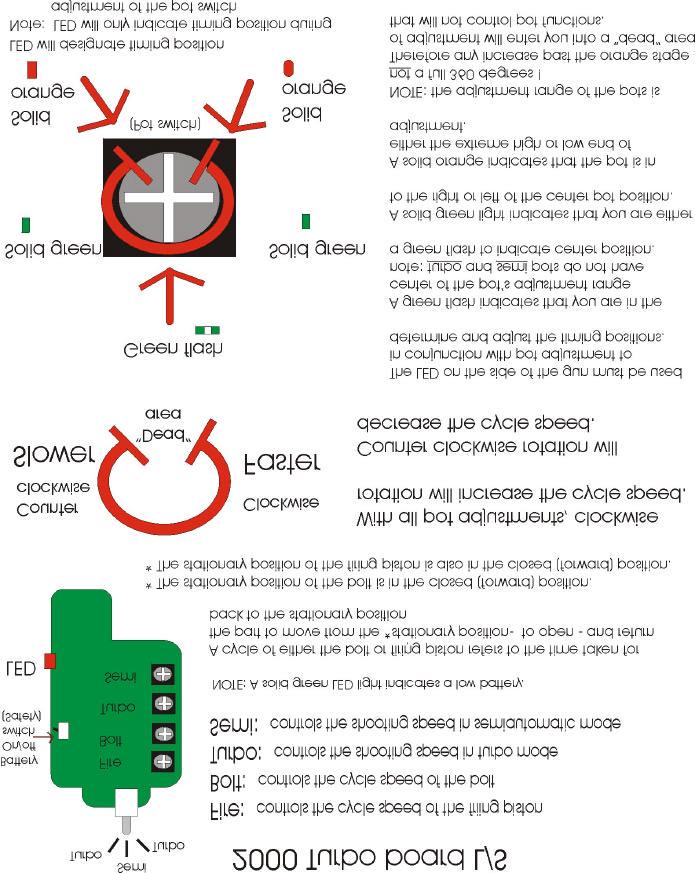
6 removed. This is done using a flat head screwdriver. Once this is unscrewed the poppet, poppet guide and spring can be removed with a pair of needle nosed pliers. The poppet housing is shown on page 13, figure 3. The two solenoids can be removed from the body by unscrewing the two mounting screws. Note: We highly recommend you DO NOT attempt to remove the solenoids because the mounting threads are easily stripped. If the threads become stripped you must purchase a new body. Velocity Adjustment The velocity of the Shocker Sport in controlled by the pressure going into the gun. This pressure, and in turn the velocity, is adjusted at the regulator. To adjust the velocity you must turn the spring housing on the regulator. The spring housing is the long black cylinder on the regulator with a hex nut at the top and a hole drilled in the bottom. To increase the velocity you must turn the spring housing in or clockwise. Caution: Do not increase the pressure over 200 psi. This will cause the solenoids to leak and the hose may burst. To decrease the velocity you must turn the spring housing out or counter clockwise. Once you have the velocity adjusted to where you want it, you should lock down the lock nut and re-chronograph your marker. Note: In order to get the proper velocity reading from your Shocker Sport you must point the barrel up when shooting across the chronograph. The Circuit Board The circuit board for the Shocker Sport controls the timing of the bolt and firing systems. The circuit board also features a built in safety switch (battery on/off switch). Two different circuit boards are available for the Shocker, the 4x4 and the Turbo board. The Turbo board allows for an impressive fire rate. Another option available through Smart Parts is the VL Revolution loader kit. This loader kit allows you to upgrade your Revolution loader. Instead of being controlled by the seeing eye, the loader is controlled by the trigger pull of the Shocker Sport. The new loader also has a speed adjustment feature, which allows you to adjust the speed of the motor in your loader. This loader also has a battery saving feature that can extend the life of your loader batteries. A picture of the circuit board is shown at the end of this section. Your Shocker Sport has two independent actions with each shot. A FIRE pulse and a BOLT pulse. The fire pulse sends the paintball down the barrel. The bolt pulse feeds a new ball into the fire chamber. Your marker has been factory set for optimum performance of both fire and bolt action. In the unlikely event that your Shocker Sport needs fine-tuning, adjustment pot switches have been provided for the fire and bolt pulses. Each pot switch has the ability to increase or decrease these pulses (see instructions on next page). 6
7 7
8 2000 L/S Board Timing Procedure Important: Timing is pre-set for each gun before it leaves the factory. Be sure that there are no mechanical problems with the gun such as: worn bolt (or bolt o-rings), un-greased parts, misplaced o-rings, or dirty or clogged pilots and solenoids. All of these circumstances could produce symptoms of a gun out of time. It is highly suggested to first clean all parts including solenoids before altering the timing settings on a circuit board. Also, please call and speak to a Shocker technician before timing the gun. Before starting timing of a gun, it is best to separate the solenoid housing from the upper body of the gun (while leaving the solenoid wires and air fittings connected). This allows a small Phillips head screwdriver to be used to access the board pot switches. Start with the battery connected; power to the board, and a pressurized gas system. Be sure that you have a good battery and a completely full tank. You must also be using a full 12-volt revolution loader with good batteries!! Note: Paintballs must be properly sized for your barrel when timing the gun! Start by rotating the fire and bolt pot switches to the center positions (green flash of the LED). You will need to then adjust the inlet pressure of the gun to achieve a shooting velocity of approximately 285 fps. With the proper velocity setting, rapid fire some shots through the gun and observe for skipped shots or double feeding. Symptoms: Double feeding - this indicates that the bolt is remaining open too long, allowing more than one ball to feed into the chamber. This can be eliminated by increasing the speed of the bolt by using a clockwise rotation on the bolt pot switch. (NOTE: With all pot switch adjustments, use small incremental adjustments.) A board that is over timed will cause the gun to drop off or beat down during rapid fire! Chopping or catching balls in feed tube - this indicates that the bolt cycle is too fast, not allowing the ball to completely drop into the chamber. This can be eliminated by using a counterclockwise rotation on the bolt switch to slow the bolt cycle that will keep the bolt open longer, allowing the ball more time to fall into the chamber. Velocity drops off - This indicates that the firing piston is not giving a large enough burst of air to expel the ball from the barrel. This can be eliminated by using a counter-clock wise rotation on the fire switch to slow the cycle of the firing piston to keep it open longer thus providing a larger burst of air to expel the ball from the barrel. (Over-timing of the bolt can also cause drop off.) Blowback in feed tube This indicates that the firing piston is staying open too long and thus delivering more than enough air needed to expel the ball from the barrel. This is eliminated by using a clockwise rotation of the fire pot switch to increase the cycle speed and therefore reduce the time the firing piston is open. 8
9 PROBLEM Trouble Shooting 9 SOLUTION 1. Gun skips shots Check LED light (on side of gun) to see if it is green, indicating that your battery will need to be replaced. Check the gun and the regulator for air leaks. Remove main bolt by unscrewing it out of the back of the gun and check o-rings on the bolt tip (the silver part with two seals) to make sure they are not twisted, cracked, or in any way damaged. If the o-rings are damaged, replace them. Make sure your loader is feeding paintballs as fast or faster than the gun is shooting. (Smart Parts recommends using a 12-volt Revolution loader.) Remove your fire piston and check the front and back o-rings for damage. Replace any damaged o-rings and re-lubricate firing piston before reinstalling. Remove and disassemble fill poppet housing. Stretch the spring inside, re-lubricate, and reassemble. Check to see if your barrel is the appropriate bore size for the paint you are using Air leaks down the barrel Remove Fire piston housing and check the o-rings on the front and back of the fire piston for twisting or damage. Re-lubricate and re-install. Shoot the gun 4 or 5 times to make sure the o- rings have seated correctly. Solenoid SH3000 is contaminated, you will need to take it apart and clean it. Call Smart Parts for assistance 2 or view instructions at 3. Bolt cycles but gun doesn t fire. Check the LED light on the side of the gun. If green, you will need to replace the battery. Check all components in the fire chamber to make sure they are well greased. This includes taking the firing cylinder out of the front of the gun and removing and re-greasing the firing piston. Check the pressure coming into the gun to ensure it is above 150psi. Also check your tank is not empty. Make sure there are no air leaks in the gun or
10 attachments. If there are, locate and repair them. Increase the fire pod on the circuit board. Refer to page 7 for instructions. Check solenoid valve for contamination (SH3000). Call Smart Parts for assistance Air leak on the inside of the gun Remove the four corner screws from the solenoid housing and split the gun in half. Check the solenoid screws to ensure they are snug, but use caution not to over-tighten and strip threads. With the body separated from the grip assembly, gas up the gun and try to locate the exact location of the leak. Call Smart Parts if assistance is needed Inconsistent velocity Clean your barrel. Point barrel upward to keep the ball from rolling out of the breach of the gun. Check your paint to see if it fits your barrel properly 1. Check regulator and gun for leaks. Check fire piston o-rings and glide rings for cuts and nicks. Check your bottle valve to ensure it is open completely. If velocity will only reach 250fps at a high pressure (about 220psi), the middle section of the SH3000 solenoid is clogged with dirt and will need to be replaced. 1. The proper way to check to see if you barrel s bore is the right size for the paint you are using is to insert a paintball into the barrel you are using. Try to blow the ball out of the barrel. If the ball is extremely hard to blow out or if it won t move at all, your bore size may be too small or your paint may be too large. If your ball rolls out the barrel easily, your paint may be too small or your barrel may be too big. If you can blow the ball out of the barrel with minimal force then your bore size is just right. Note: It is best to try this with a number of paintballs as they may vary from ball to ball. 2. Please call Smart Parts at How-to guides are also available at When calling Smart Parts, make sure you have your gun and tools in front of you in order to remedy problem. 10
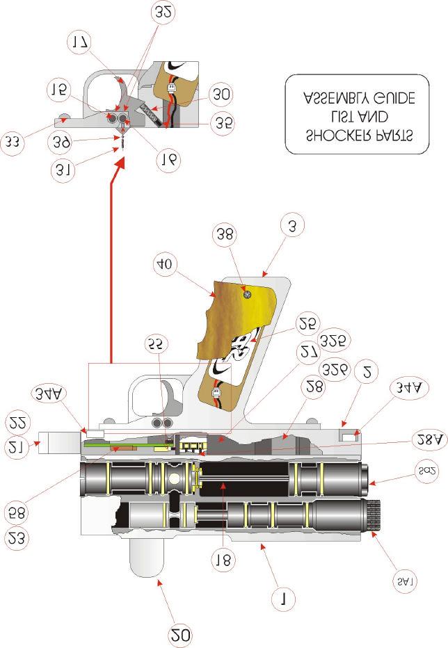
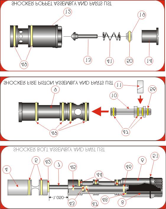
11 Shocker Parts (Page 12) Parts List for the Shocker Sport 1. Gun Body 31. Safety Spring 2. Solenoid Housing 32. Circlip 3. Grip Frame 33. Grip Frame Screw 15. Trigger Pin 34A. Solenoid Housing Screw 16. Safety Pin 35. Trigger Screw 17. Trigger 38. Grip Screw 18. Push Rod 39. Safety Ball 20. Ball Tube 40. Grip 21. Switch Cover (Tournament) 55. Circuit Board Screw 22. Switch Cover (Recreational) 58. Turbo Circuit Board 23. 4X4 Circuit Board 200. Filter 25. Battery Way Spool (part of 27) Way Solenoid Way Spool (part of 28) Way Solenoid 337. Pilot (part of 27 & 28) 28A. Solenoid Gaskets and Screws 455. Coil Complete (part of 27 & 28) 30. Trigger Spring Bolt Assembly (Page 13) 4. Bolt Tip 43. Piston Bumper 5. Bolt Tip Seals 44. Bolt Cylinder Seal (outer) 6. Bolt Cylinder 45. Bolt Cylinder Seal (inner) 7. Bolt Piston 46. Piston Cylinder Seal 8. Bolt Piston Guide 47. Bolt Piston Seal/Firing Piston Seal 18. Bolt Piston 48. Piston Guide Seal 42. Bolt Bumper 51. Bolt Cylinder End Seal Fire Piston Assembly (Page 13) 9. Firing Cylinder 47. Firing Piston Seal/Bolt Piston Seal 10. Firing Piston 49. Firing Cylinder Seal/Poppet Seat Seal 11. Firing Piston Guide/Glide Ring 56. Firing Piston Seal Front Poppet Assembly (Page 13) 12. Poppet Seat 19. Poppet Bearing 13. Poppet 41. Poppet Spring 14. Poppet Guide 49. Poppet Seat Seal/Firing Cylinder Seal 50. Poppet Guide Seal 11
12 12
13 13
14 14
15 Disassembly of Bolt Disassembly/Reassembly Instructions 1. Remove back end cap from bolt and o-rings from bolt tip, 2. Heat the lower end of the bolt head to loosen the Loctite connecting the bolt head, bolt piston, 3. After the Loctite has been loosened use a flathead screw driver and unscrew the bolt piston from the bolt head through the rear of the bolt (the back of the bolt piston has a groove in it to fit a flathead screw driver), 4. When the bolt head is unscrewed, the bolt piston can be removed from the bolt housing and checked for damage or needed maintenance. Reassembly of Bolt 1. Apply a heavy coating of grease to the bolt piston o-rings, 2. Slide the smaller bolt bumper over the front of the bolt piston, insert bolt piston into bolt housing, 3. Place larger bolt bumper in between bolt head and bolt housing on bolt piston, 4. Clean bolt head and bolt piston threads with alcohol, 5. After threads are clean and dry apply 680 Green Loctite and reassemble, 6. Screw bolt piston into bolt head until snug. 7. Allow to dry for 30 minutes, minimum, 8. Replace bolt tip o-rings. Disassembly and Cleaning of Both Solenoids 1. Using a small phillips head screw driver, remove the black cap at end of solenoid (positioned at the silver end of solenoid), 2. When removing cap notice the line on the bottom of the cap (the cap MUST be reassembled with the line facing down or solenoid will leak!!), 3. When the cap is taken off remove the cone shaped spring, 4. Using a pair of needle nose pliers pull the shaft out of the solenoid and inspect shaft o-rings for damage or debris. Reassembly of Solenoids: 1. Grease solenoid shaft and o-rings, 2. Reinsert solenoid shaft with pointed end facing out. 3. Place cone shaped spring over shaft with small end facing shaft, 4. Place cap over spring and shaft (with line on cap facing down) and reinsert phillips head screws. 5. Snug down screws DO NOT OVER TIGHTEN!!! 15
16 Gun Will Not Fire Check Battery If good, continue If bad, replace Check Fire Piston and Housing for cracks or breaks. Clean and re-grease, make sure Fire Rod is in place, replace Piston and Housing. Try gun again. Still not working That worked! Make sure Poppet is screwed all the way in. Try gun again. Still not working Split gun, check wires for breaks or crushed. If smashed, reposition wires and try again Still not working Press manual button on SH3000 solenoid. If the gun fires, try pulling the trigger. If the gun works with the manual button, but not with the trigger If the gun does not work at all The problem could be a bad coil or bad electronic board. Replace or call Smart Parts. The solenoid must have dirt in it, or the pilot in the solenoid must be plugged. See expanded view of chart or call Smart Parts. 16
TABLE OF CONTENTS SAFETY FIRST!...3 BASIC OPERATION...4 ADJUSTMENTS...5. Cocking Pressure...5. Three-Way Valve Adjustment...6
 TABLE OF CONTENTS SAFETY FIRST!...3 BASIC OPERATION...4 ADJUSTMENTS...5 Cocking Pressure...5 Three-Way Valve Adjustment...6 External Three-Way adjustment...6 In-Line Regulator...6 Ram to Cocking Block
IMPORTANT CO2/ HPA AIR TANK SAFETY INSTRUCTION AND GUIDELINES. Tank valves must be installed or removed by qualified personnel.
 !WARNING! IMPORTANT SAFETY INSTRUCTION AND GUIDELINS!WARNING! IMPORTANT CO2/ HPA AIR TANK SAFETY INSTRUCTION AND GUIDELINES GETTING STARTED This Paintball Marker is NOT A TOY. Misuse can cause serious
WARNING TABLE OF CONTENTS:
 WARNING WARNING: This is not a toy. Misuse may cause serious injury or death. Eye protection designed specifically for paintball must be worn by the user and persons within range. Recommend 18 years of
! WARNING! IMPORTANT HPA AIR TANK SAFETY INSTRUCTION AND GUIDELINES ! WARNING! IMPORTANT SAFETY INSTRUCTION AND GUIDELINES
 ! WARNING! IMPORTANT SAFETY INSTRUCTION AND GUIDELINES! WARNING! IMPORTANT HPA AIR TANK SAFETY INSTRUCTION AND GUIDELINES This Paintball Marker is NOT A TOY. Misuse can cause serious injury or death. It
MAYHEM MAYHEM OWNERS MANUAL. Paintball Guns International. Manufactured by
 MAYHEM MAYHEM OWNERS MANUAL Manufactured by Paintball Guns International Table of Contents Specifications...................... 2 Parts diagram and Listing............. 3 Description of Marker Operation.......
IMPORTANT CO2/ HPA AIR TANK SAFETY INSTRUCTION AND GUIDELINES. Tank valves must be installed or removed by qualified personnel.
 !WARNING! IMPORTANT SAFETY INSTRUCTION AND GUIDELINS!WARNING! IMPORTANT CO2/ HPA AIR TANK SAFETY INSTRUCTION AND GUIDELINES GETTING STARTED This Paintball Marker is NOT A TOY. Misuse can cause serious
VIBE. Quick Start Manual
 VIBE Quick Start Manual STATISTICS PLEASE READ CAREFULLY VITAL STATISTICS LENGTH/HEIGHT/WEIGHT: OPERATING PRESSURE: PAINTBALLS: POWER SOURCE: PROPELLANT: RATE OF FIRE: OPERATION: MODES OF FIRE: ANTI CHOP
Cover.qxd 1/10/05 10:30 AM Page 2. user manual. diablopaintball.com
 Cover.qxd 1/10/05 10:30 AM Page 2 user manual Cover.qxd 1/10/05 10:30 AM Page 3 Table Of Contents: Page Topic(s) 1 Warning and Rules Safe Marker Handling 2 Warranty Information 3 Welcome 4 Battery Installation
user manual .68 CALIBER ELECTRONIC PAINTBALL MARKER Meets or exceeds ASTM standards.
 user manual TM TM TABLE OF CONTENTS: Page Topic(s) 1 Warning and Rules Safe Marker Handling 2 Warranty Information 3 Welcome 4 Initial Assembly 6 Parts Key 7 Exploded Diagram 8 Battery Installation 9 Attaching
E-MAG TM Instruction Manual
 E-MAG TM Instruction Manual SAFETY THIS PAINTBALL MARKER IS NOT A TOY! This paintball marker should be treated as a dangerous instrument and should always be treated with respect. Never point a paintball
user manual .68 CALIBER ELECTRONIC PAINTBALL MARKER Meets or exceeds ASTM standards.
 user manual TM TM TABLE OF CONTENTS: Page Topic(s) 1 Warning and Rules Safe Marker Handling 2 Warranty Information 3 Welcome 4 Initial Assembly Battery Installation 9 Attaching Propellant Source Attaching
Play Safe. Safety. Instruction Manual. Warning. Rebel Specifications
 Operation Guide Instruction Manual Congratulations on your purchase of the 32 Degrees Rebel Xtreme semi-auto. Before you use this marker, please read this manual in its entirety. Please follow all safety
FIRESTORM. Assembly Instructions. Electric Upgrade Kit for the Autococker. Designed & Manufactured by PGI
 FIRESTORM Electric Upgrade Kit for the Autococker Assembly Instructions Designed & Manufactured by PGI Table of Contents Introduction 1 Safety 1 Parts Diagram 2 Parts Diagram Listing 2 Getting Started
WARNING. Paintball Pistol. Paintball Pistol
 This lightweight assault paintball pistol is custom milled from high grade aluminum for superb balance and precision. The compact construction of this competition paintball pistol will give you a mobile
TABLE OF CONTENT IMPORTANT HPA AIR TANK SAFETY INSTRUCTIONS AND GUIDELINES RYSE ON/OFF ASA GETTING STARTED O-RING LIST SCREW LIST MICRO SQ BOARD
 TABLE OF CONTENT 4 IMPORTANT HPA AIR TANK SAFETY INSTRUCTIONS AND GUIDELINES 22 RYSE ON/OFF ASA 6 GETTING STARTED 23 O-RING LIST 8 MICRO SQ BOARD 25 SCREW LIST 6 TRIGGER ADJUSTMENT 28 INTERNAL PARTS 7
SAFETY Always wear approved safety goggles or an approved mask whenever you handle this paintball marker!
 Instruction Manual Table of Contents SAFETY... 1 COMPRESSED AIR ONLY... 2 FAST START... 3 FIRST TIME PROBLEMS... 4 PERFORMANCE... 4 LUBRICATION... 5 VELOCITY ADJUSTMENT... 5 CLEANING... 5 PAINTBALLS...
Synergy Owners Manual
 Synergy Owners Manual Table of Contents Safety Guidelines...2 Quickstart Guide...3 Owners Manual...7 Field Strip Guide...11 Do s & Don ts...12 Diagrams...13 Troubleshooting Guide...15 Warranty Info...16
Paintball Marker. User s Manual. 530 South Springbrook Road Newberg, OR 97132
 Paintball Marker User s Manual 530 South Springbrook Road Newberg, OR 97132 Component Concepts, Inc., 530 South Springbrook Road, Newberg, OR 97132 Phone: (503) 554-8095 Fax: (503) 554-9370 www.phantomonline.com
ProMaster Troubleshooting Guide
 ProMaster Troubleshooting Guide Always read your owner's manual before operating or doing maintenance on your ProMaster marker. The manual contains in-depth maintenance and setup information. Always remove
TABLE OF CONTENTS. AIR SOURCE : CO2/HPA ONLY (not included)
") Owner s Manual INCLUDES -.68 CALIBER CONQU3ST PAINTBALL MARKER - 10.5 ONE PIECE BARREL (AUTOCOCKER THREAD) - SPARE PARTS KIT - TOOL KIT - BARREL BLOCKING DEVICE AIR SOURCE : CO2/HPA ONLY (not included)
Owner s Manual INCLUDES -.68 CALIBER CONQU3ST PAINTBALL MARKER - 10.5 ONE PIECE BARREL (AUTOCOCKER THREAD) - SPARE PARTS KIT - TOOL KIT - BARREL BLOCKING DEVICE AIR SOURCE : CO2/HPA ONLY (not included)
Thank you for purchasing your new Empire Reloader B Sound-Activated 3-Speed Paintball Hopper!
 Thank you for purchasing your new Empire Reloader B Sound-Activated 3-Speed Paintball Hopper! Should you require any technical assistance on the use of this product, or if your product needs servicing,
TIPPMANN 98 CUSTOM. Owner s Manual CO2 POWERED PAINTBALL GUN
 TIPPMANN PNEUMATICS, INC. Get Your ur Heart t Pound unding With h A Tippmann! WARNING: This paintball marker/gun is not a toy nor is it intended for unsupervised use by persons under the age of 18 years.
IMPORTANT CO2/ HPA AIR TANK SAFETY INSTRUCTION AND GUIDELINES. Tank valves must be installed or removed by qualified personnel.
 !WARNING! IMPORTANT SAFETY INSTRUCTION AND GUIDELINS!WARNING! IMPORTANT CO2/ HPA AIR TANK SAFETY INSTRUCTION AND GUIDELINES GETTING STARTED This Paintball Marker is NOT A TOY. Misuse can cause serious
BT_SA-17_Manual.qxp 3/11/10 9:54 AM Page C
 BT_SA-17_Manual.qxp 3/11/10 9:54 AM Page C OWNER S MANUAL BT_SA-17_Manual.qxp 3/11/10 9:54 AM Page D CONTENTS 1. Rules for Safe Marker Handling..............................1 2. Introduction and Specifications..............................1
WARNING OWNER S MANUAL WARSENSOR WSP PAINTBALL PISTOL
 WARSENSOR WSP PAINTBALL PISTOL OWNER S MANUAL WARNING WARSENSOR PAINTBALL MARKERS ARE NOT A TOY. ANY MISUSE MAY CAUSE SERIOUS INJURY OR DEATH. THE USER AND ANY PERSON WITHIN RANGE MUST WEAR EYE PROTECTION
WARNING OLED & BASIC MENU QUICK START
 Getting Started QUICK START WARNING The VANGUARD MARKER is not a toy. Careless or improper use, including failure to follow instructions and warnings within this Operator Manual and attached to the VANGUARD
WARNING continued: 14. Never put any body parts or foreign objects into the breech or feed tube. 15. Always use the supplied barrel cover when your
 owner s manual 1 Owner s Manual 2 WARNING: 1. The DP G5 SPEC-R is NOT A TOY. Treat it with the same respect and care you would a firearm. 2. Carelessness, Misuse, and failure to adhere to the warning and
O W N E R S M A N U A L E M P I R E P A I N T B A L L. C O M
 OWNER S MANUAL CONTENTS 1. Rules for Safe Marker Handling...1 2. Introduction and Specifications...1 3. Battery Replacement and Life Indicator...2 4. Compressed Air/Nitrogen Supply...2 5. Basic Operation...3
TABLE OF CONTENTS DM4 OWNER S MANUAL QUICK REFERENCE...PAGE 02 IMPORTANT SAFETY INSTRUCTIONS AND GUIDELINES...PAGE 03
 < < S P E C S > > WEIGHT [.3 LBS] WIDTH [.37 ] LENGTH [9.7 ] HEIGHT [8. ] EFFICIENCY [,00 SHOTS OFF 68CU 400PSI] BATTERY LIFE [40,000 SHOTS] OPERATING PRESSURE [7PSI] CYCLE PRESSURE [7PSI] MAX RATE OF
PROPORTIONING VALVE. Model 150 INSTRUCTION MANUAL. March 2017 IMS Company Stafford Road
 PROPORTIONING VALVE Model 150 INSTRUCTION MANUAL March 2017 IMS Company 10373 Stafford Road Telephone: (440) 543-1615 Fax: (440) 543-1069 Email: sales@imscompany.com 1 Introduction IMS Company reserves
Pilot JAVA 9.6V RECHARGEABLE BATTERY & CHARGER INCLUDED. Kingman Group Live Oak Avenue, Baldwin Park, CA 91706, U.S.A. Toll-free 888.
 Pilot Kingman Group 14010 Live Oak Avenue, Baldwin Park, CA 91706, U.S.A. Toll-free 888.KINGMAN www.kingman.com JAVA 9.6V RECHARGEABLE BATTERY & CHARGER INCLUDED 14010 Live Oak Avenue, Baldwin Park, CA
Paintball Marker. User s Manual. Direct Feed. SC: Stock Class. VSC: Vertical Air Stock Class. 530 South Springbrook Road Newberg, OR 97132
 Paintball Marker User s Manual Direct Feed SC: Stock Class 530 South Springbrook Road Newberg, OR 97132 VSC: Vertical Air Stock Class www.phantomonline.com Component Concepts, Inc., 530 South Springbrook
Freedom8 ShoeBox Compressor Manual
 Freedom8 ShoeBox Compressor Manual Warning!! This product is not a toy! Use or misuse can cause severe injury or death! Use only with adult supervision. This unit is only to be used with tanks, hoses and
CONTENTS. Read this entire manual before loading, or installing an air cylinder, or in any way attempting to operate the marker
 OWNER S MANUAL CONTENTS 1. Rules for Safe Marker Handling 2. Introduction and Specifications 3. Battery Replacement and Life Indicator 4. Basic Operation 5. Compressed Air/Nitrogen Supply 6. Installing
Proto Paintball USA EUROPE ASIA
 Proto Paintball USA 10637 Scripps Summit Ct. San Diego, CA 92131 P 858-536-5183 F 858-536-5191 EUROPE Unit 1, ZK Park, 23 Commerce Way Croydon, Surrey CRO 4ZS United Kingdom P +44 (0) 20-8649-6330 F +44
Autococker Marker Manual
 Autococker Marker Manual Autococker Trilogy Select-Fire Manual WORR GAME PRODUCTS, LLC. TRILOGY AUTOCOCKER OWNERS MANUAL WARNING: This Always is not wear a toy. paintball Misuse approved may cause eye
MODEL 1410 OWNER S MANUAL
 2111 S. 8th, Rogers, Ar 72758 U.S.A. (501) 636-1200 Fax (501)636-0573 http://www.brasseagle.com THIS BOOKLET CONTAINS: Safety Information Warranty Registration Annotated Diagram Operating Instructions
Booster Pump PB4-60 Replacement Kits
 Booster Pump PB4-60 Replacement Kits FOR YOUR SAFETY - This product must be installed and serviced by a contractor who is licensed and qualified in pool equipment by the jurisdiction in which the product
 www.empirepaintball.com 1. SAFE MARKER HANDLING IMPORTANT: Never carry your marker uncased when not on a playing field. The non-playing public and law enforcement personnel may not be able to distinguish
User Instruction Manual
 User Instruction Manual 4500 psi Air Compressor Ver 2, 1.18 Contents Parts Included...3 Assembly Instructions...3-5 Operation Instructions...6-7 Oil Change Intervals...8 Air Filter Replacement...9 Setting
Aluminum 13 cu tank Includes regulator Fill pressure: 3,000 psi (200 bar) Output: 1,100 psi +/- 10% (75bar)
 Output: 1,100 psi +/- 10% (75bar)") Aluminum 13 cu tank Includes regulator Patent numbers: 6,851,447 7,059,343 7,051,751 Fill pressure: 3,000 psi (200 bar) Output: 1,100 psi +/- 10% (75bar) Contents Safety system... 3 Fill your tank... 4
Aluminum 13 cu tank Includes regulator Patent numbers: 6,851,447 7,059,343 7,051,751 Fill pressure: 3,000 psi (200 bar) Output: 1,100 psi +/- 10% (75bar) Contents Safety system... 3 Fill your tank... 4
IMPORTANT SAFETY GUIDELINES !CAUTION!
 USERS MANUAL TABLE OF CONTENTS IMPORTANT SAFETY GUIDELINES 1 OPERATION GUIDE / START UP 2 CO2 / COMPRESSED AIR TANK 3-4 ELECTRONICS & SETTINGS 5-6 BATTERY CHARGING 7-8 VELOCITY ADJUSTMENT 9 SHOULDER STOCK
1799 Carpenter Road Oakley, California Operator s M a n u a l
 1799 Carpenter Road Oakley, California 94561 2 0 0 5 Operator s M a n u a l Table of Contents Section Page Safety.....................................................2 Warranty...................................................3
STATEMENT OF LIABILITY
 STATEMENT OF LIABILITY LASERLINE IS MANUFACTURED BY WEST INDUSTRIES INC. LASERLINE IS PATENTED AND TRADEMARKED. This device is not a toy. Misuse may cause serious injury. The user and any person within
Proto Paintball USA EUROPE ASIA
 Proto Paintball USA 10637 Scripps Summit Ct. San Diego, CA 92131 P 858-536-5183 F 858-536-5191 EUROPE Dye House, 7-8 Commerce Way Croydon, Surrey, CR0 4XA, United Kingdom P +44 (0) 20-8649-6330 F +44 (0)
SAFETY WARNING MUST READ
 Airgun Designs Inc. Table of Contents SAFETY...1-2 COMPRESSED AIR ONLY... 2 FAST START... 3 LvL 10 ANTI-CHOP SYSTEM... 4 LOADER...4 PERFORMANCE... 4 LUBRICATION... 4 VELOCITY ADJUSTMENT... 5 BLOW-OFF VALVE...
BUSHMASTER 2000 / 2K2 (LCD) MANUAL. BushMaster 2000 Overview
 MANUAL. BushMaster 2000 Overview") BUSHMASTER 2000 / 2K2 (LCD) MANUAL BushMaster 2000 Overview The BushMaster 2000 is a quality marking instrument specially designed to meet the needs of the professional style tournament player. The BushMaster
BUSHMASTER 2000 / 2K2 (LCD) MANUAL BushMaster 2000 Overview The BushMaster 2000 is a quality marking instrument specially designed to meet the needs of the professional style tournament player. The BushMaster
SPECIFICATIONS Type: Twin stack, single phase Tank: 4 gallon Air Output: PSI; PSI Max PSI: 125 PSI HP: 1.
 2 GALLON TWIN STACK AIR COMPRESSOR Model: 9526 DO NOT RETURN TO STORE. Please CALL 800-348-5004 for parts and service. CALIFORNIA PROPOSITION 65 WARNING: You can create dust when you cut, sand, drill or
Welker Sampler. Model GSS-1. Installation, Operation, and Maintenance Manual
 Installation, Operation, and Maintenance Manual Welker Sampler Model GSS-1 The information in this manual has been carefully checked for accuracy and is intended to be used as a guide to operations. Correct
INTRODUCING THE G.I. SPORTZ VICTUS WARRANTY
 INTRODUCING THE G.I. SPORTZ VICTUS The G.I. Victus was created in collaboration with Bob Long Domestic Gun Developer for the last 20 years. The Marker was designed to give its user the fastest rate of
O p e r a t o r s M a n u a l A - B o m b D a r k R i p p e r 2 R i p p e r ivera R obert R by esign D & Photography
 O p e r a t o r s M a n u a l A-Bomb Dark Ripper 2 Ripper 2.5 Photography & Design by Robert Rivera - 305.819.1009 Table of Contents Section Page Safety.....................................................2
RG1200 Service and Repair Manual
 Dive Rite RG 1200 Regulator Service and Repair Manual Page 1 Text and Photography by Pete Nawrocky Copyright ( ) 1999-2000, Lamartek, Inc., dba Dive Rite RG1200 Service and Repair Manual First Stage.........................................
Constant Pressure Crude Oil Container Model CPCCP
 Installation, Operations, and Maintenance Manual Constant Pressure Crude Oil Container Model CPCCP The information in this manual has been carefully checked for accuracy and is intended to be used as a
O P E R A T O R S M A N U A L
 OPERATOR S MANUAL WARNING! This is not a toy. Misuse may cause serious injury or death. Eye protection designed specifically for paintball must be worn by the user and persons within range. Must be 18
dye Precision, Inc. USA Scripps Summit Ct. San Diego, CA P f
 O W N E R S M A N U A L dye Precision, Inc. USA 10637 Scripps Summit Ct. San Diego, CA 92131 P 858-536-5183 f 858-536-5191 GERMANY Albert Einstein Str. 2 B 77656 Offenburg, Germany P +49 (0)781 639 349
Installation, Operation, and Maintenance Manual
 Installation, Operation, and Maintenance Manual Welker The information in this manual has been carefully checked for accuracy and is intended to be used as a guide for the installation, operation, and
Hydraulic Punch Drivers
 SERVICE MANUAL 7804SB / 7806SB Quick Draw 7704SB / 7706SB Quick Draw Flex Quick Draw Hydraulic Punch Drivers Serial Codes AHJ and YZ Read and understand all of the instructions and safety information in
TABLE OF CONTENTS Section Page Safety Warranty
 GEN4 I N T I M I D A T O R A L E G E N D R E B O R N TABLE OF CONTENTS Section Page Safety..............................................................................2 Warranty............................................................................3
TABLE OF CONTENTS IMPORTANT SAFETY INSTRUCTIONS AND GUIDELINES... PAGE 02 QUICK REFERENCE... PAGE 04 BOARD SETTINGS AND FUNCTIONS...
 D M 9 O W N E R S M A N U A L TABLE OF CONTENTS IMPORTANT SAFETY INSTRUCTIONS AND GUIDELINES......................... PAGE 02 QUICK REFERENCE........................................................ PAGE
CAUTION: READ ALL WARNINGS BEFORE USING OR ATTEMPTING ANY WORK ON YOUR MARKER. SHOULD YOU BE UNSURE AT ANY POINT, STOP AND SEEK PROFESSIONAL SUPPORT.
 Marq Victory Pump Bob Long Technologies MVP Bob Long Technologies 09-93-4440 www.boblongdirect.com Table of Contents Warning... 3 Warranty... 3 Introducing the MVP... 4 Ready for the Field... 4 Quick Start...
MECH-TECH SYSTEMS CCU MODEL FOR GLOCK PISTOLS
 MECH-TECH SYSTEMS CCU MODEL FOR GLOCK PISTOLS Operation & Maintenance Manual Read and understand this manual before attempting to use this product. If you have any questions call: 1-866-433-2122 www.mechtechsys.com
Installation, Operation, and Maintenance Manual
 Installation, Operation, and Maintenance Manual Welker Probe Instrument Regulator Model The information in this manual has been carefully checked for accuracy and is intended to be used as a guide for
T4.1 MAGAZINE & HOPPER-FED PAINTBALL RIFLE TIBERIUS ARMS TECHNICAL MANUAL
 T4.1 MAGAZINE & HOPPER-FED PAINTBALL RIFLE TIBERIUS ARMS TECHNICAL MANUAL TECHNICAL MANUAL T4.1 MAGAZINE & HOPPER-FED PAINTBALL RIFLE TABLE OF CONTENTS Warnings...Page 1 T4.1 Rifle Diagram...Page 2 Universal
Pressure Dump Valve Service Kit for Series 2300 Units
 Instruction Sheet Pressure Dump Valve Service Kit for Series 00 Units. Overview The Nordson pressure dump valve is used to relieve hydraulic pressure instantly in Series 00 applicator tanks when the unit
12S 1st Stage. -Maintenance Procedure-
 12S 1st Stage -Maintenance Procedure- 1 Warning! All maintenance and repair procedures MUST be performed by a Mares authorized Service Center and/or Distributor. Therefore, the information provided below
G7S Hand Pump Owner s Manual
 G7S Hand Pump Owner s Manual Copyright Air Venturi 2018 Version 4-18 Specifications 24.80 inches long closed 43.31 inches long extended 4500 psi/310 bar max pressure Features Integral manometer (pressure
DM8 manual.qx6 10/8/07 5:14 PM Page 1
 DM8 manual.qx6 10/8/07 5:14 PM Page 1 DYE Precision, Inc. USA 10637 Scripps Summit Ct. San Diego, CA 92131 P 858-536-5183 F 858-536-5191 EUROPE Unit 1, ZK Park, 23 Commerce Way Croydon, Surrey CRO 4ZS
Operating Instructions Model and Hydrostatic Test Pump
 Operating Instructions Model 39300 and 39301 Hydrostatic Test Pump Dimension Weight Pump Style Capacity Pressure Motor Lubrication Control Gauge Inlet Connection Outlet Connection Discharge Hose Hose Ends
5 Gallon Pressure Pot with HVLP Spray Gun and Hose
 California Air Tools 5 Gallon Pressure Pot with HVLP Spray Gun and Hose Model No. 365 Technical Data Type of feed.pressure Maximum pressure in the tank... 0,413Mpa (60PSI) Working pressure in the tank.0,
INSTALLATION, OPERATION, AND MAINTENANCE MANUAL WELKER RELIEF VALVE
 INSTALLATION, OPERATION, AND MAINTENANCE MANUAL WELKER RELIEF VALVE MODELS RV-1 RV-2 RV-2CP RV-3 DRAWING NUMBERS AD017A[ ] AD018A[ ] AD020A[ ] AD282BO MANUAL NUMBER IOM-033 REVISION Rev. E, 3/28/2016 TABLE
ARIAKON. Thank you for choosing ARIAKON. ARE YOU A PLAYER?
 Page 20 Page 1 Thank you for choosing ARIAKON. ARIAKON www.ariakon.com 2794 LOKER AVE WEST SUITE 107 CARLSBAD CA 92008 Phone: 1-877-4-ARIAKON 760-268-0735 FAX: 760-268-0736 Email: sales@ariakon.com ARE
This Manual was downloaded from the Paintball Gun Service Manuals list.
 This Manual was downloaded from the Paintball Gun Service Manuals list. Proto Paintball USA 10637 Scripps Summit Ct. San Diego, CA 92131 P 858-536-5183 F 858-536-5191 EUROPE UNITED KINGDOM Dye House, 7-8
MAINTENANCE PROCEDURE FOR X 650
 MAINTENANCE PROCEDURE FOR X 650 X 650 25. juli 2005-1/6 MAINTENANCE PROCEDURE FOR X 650 2 ND STAGE WARNING: This maintenance procedure is only for appointed Scubapro technicians that completed a course
CS150 CAP STAPLER OWNER S MANUAL
 Operation Revised 6/2013 www.stingerworld.com CS150 CAP STAPLER OWNER S MANUAL! Maintenance Safety Warranty PLEASE READ! This manual contains important information about product safety. WELCOME TO STINGER
Carbon Fiber Tank with EZ Fill system Fill pressure 4,500 psi (310 bar) Output: up to 4,500 psi (310 bar)
 Output: up to 4,500 psi (310 bar)") Carbon Fiber Tank with EZ Fill system Fill pressure 4,500 psi (310 bar) Output: up to 4,500 psi (310 bar) Ver 1, 10/18 Contents Safety System...3 Filling The Air Venturi Ez Fill System...4 Micro Bore Hose
Carbon Fiber Tank with EZ Fill system Fill pressure 4,500 psi (310 bar) Output: up to 4,500 psi (310 bar) Ver 1, 10/18 Contents Safety System...3 Filling The Air Venturi Ez Fill System...4 Micro Bore Hose
TABLE OF CONTENTS INCLUDED WITH YOUR MATRIX ADDITIONAL RECOMMENDED TOOLS QUICK REFERENCE...PAGE 02
 M A T R I X O W N E R S M A N U A L TABLE OF CONTENTS QUICK REFERENCE.....................................................................................................PAGE 02 IMPORTANT SAFETY INSTRUCTIONS
Service and Repair Manual
 II stage R2 Ice/ Special, II stage R 1 Pro DOWNSTREAM 2 nd STAGE REGULATOR Service and Repair Manual Introduction Safety Precautions...4 General Procedures, Maintenance Schedules...5 Initial Inspection
TABLE OF CONTENTS 2014 DM SERIES OWNER S MANUAL IMPORTANT SAFETY INSTRUCTIONS AND GUIDELINES... PAGE 02 QUICK REFERENCE... PAGE 04
 2014 DM SERIES OWNER S MANUAL TABLE OF CONTENTS IMPORTANT SAFETY INSTRUCTIONS AND GUIDELINES... PAGE 02 QUICK REFERENCE... PAGE 04 BOARD SETTINGS AND FUNCTIONS... PAGE 06 REACH AIRPORT... PAGE 12 INCLUDED
Model PSI Compressor with 3-Gallon Air Tank 12VDC
 Model 6350 150 PSI Compressor with 3-Gallon Air Tank 12VDC IMPORTANT: It is essential that you and any other operator of this product read and understandd the contents of this manual before installing
Instruction Manual Updated 7/26/2011 Ver. 2.2
 4-Unit Model MB HTHP Filter Press #171-50-4: 115-Volt #171-51-4: 230-Volt Instruction Manual Updated 7/26/2011 Ver. 2.2 OFI Testing Equipment, Inc. 11302 Steeplecrest Dr. Houston, Texas 77065 U.S.A. Tele:
PM8 manual-final.qx6 10/4/07 1:06 PM Page 1
 PM8 manual-final.qx6 10/4/07 1:06 PM Page 1 Proto Paintball USA 10637 Scripps Summit Ct. San Diego, CA 92131 P 858-536-5183 F 858-536-5191 EUROPE Unit 1, ZK Park, 23 Commerce Way Croydon, Surrey CRO 4ZS
LIQUIP DRYBREAK COUPLER. API800 Series MAINTENANCE INSTRUCTIONS
 LIQUIP DRYBREAK COUPLER API800 Series MAINTENANCE INSTRUCTIONS API LOADING COUPLER TO API RP1004 June 2015 Issue: F M:\Product-Info\API8xx\6-Service-Maintenance\API800 MAINTENANCE INSTRUCTIONS 40183.doc
Pressure Dump Valve Service Kit for Series 3000 Units
 Instruction Sheet Pressure Dump Valve Service Kit for Series 000 Units. Overview The Nordson pressure dump valve is used to relieve hydraulic pressure instantly in Series 00, 400, 500, and 700 applicator
2 GALLON TWIN STACK AIR COMPRESSOR W/ HOSE REEL
 2 GALLON TWIN STACK AIR COMPRESSOR W/ HOSE REEL Model: 52024 CALIFORNIA PROPOSITION 65 WARNING: You can create dust when you cut, sand, drill or grind materials such as wood, paint, metal, concrete, cement,
BT PAINTBALL DESIGNS, INC. 570 MANTUA BLVD., SEWELL, NJ
 Rip Clip Manual_2.qxp 4/15/08 11:00 AM Page a BT PAINTBALL DESIGNS, INC. 570 MANTUA BLVD., SEWELL, NJ 08080 WWW.BTPAINTBALL.COM Rip Clip Manual_2.qxp 4/15/08 11:00 AM Page b BT Paintball would like to
Contents. Stainless Steel Side Block. 1.1 Separating the Side Block. Stainless Steel Side Block Reassembly of. Assembly from the Helmet Shell
 Separating the Side Block Assembly from the Helmet Shell Contents SSB-1 SSB-3 SSB-5 SSB-5 SSB-7 1.1 Separating the Side Block Assembly from the Helmet Shell 1.2 Side Block Assembly Replacement 1.3 Defogger
FX IMPACT OWNER S MANUAL
 made in sweden FX IMPACT OWNER S MANUAL Warranty Information All FX Airguns carry a One Year Warranty against faulty workmanship and defective materials. If it becomes necessary, first contact the dealer
200 PSI COMPRESSORS - MODEL NUMBERS
 200 PSI COMPRESSORS - MODEL NUMBERS 380C AIR COMPRESSOR KIT PART NO. 38033 480C AIR COMPRESSOR KIT PART NO. 48043 380C 480C IMPORTANT: It is essential that you and any other operator of this product read
Carbon fiber tank Includes regulator & fill station with hose Fill pressure: 4,500 psi (310 bar) Output: 2,900 psi +/- 10% (200 bar)
 Output: 2,900 psi +/- 10% (200 bar)") Carbon fiber tank Includes regulator & fill station with hose Patent numbers: 6,851,447 7,059,343 7,051,751 Fill pressure: 4,500 psi (310 bar) Output: 2,900 psi +/- 10% (200 bar) Contents Safety system...
Carbon fiber tank Includes regulator & fill station with hose Patent numbers: 6,851,447 7,059,343 7,051,751 Fill pressure: 4,500 psi (310 bar) Output: 2,900 psi +/- 10% (200 bar) Contents Safety system...
Rip Clip Manual_2.qxp 4/15/08 11:00 AM Page c
 Rip Clip Manual_2.qxp 4/15/08 11:00 AM Page b Rip Clip Manual_2.qxp 4/15/08 11:00 AM Page c Rip Clip Manual_2.qxp 4/15/08 11:00 AM Page 1 BT Paintball would like to thank you for your purchase of the BT
100C Air Compressor Kit
 10010 100C Air Compressor (standard mounting bracket, CE Spec) 10014 100C Air Compressor (no leader hose or check valve, CE Spec) 10016 100C Air Compressor (with Omega Bracket, CE Spec) IMPORTANT: It is
AR STYLE FIREARMS OWNER'S MANUAL: OPERATION, HANDLING, DISASSEMBLY / REASSEMBLY & SAFETY INSTRUCTIONS
 AR STYLE FIREARMS OWNER'S MANUAL: OPERATION, HANDLING, DISASSEMBLY / REASSEMBLY & SAFETY INSTRUCTIONS - DO NOT DISCARD THIS MANUAL - READ THIS MANUAL CAREFULLY, PAYING CLOSE ATTENTION TO THE INSTRUCTIONS
MILSIG HEAT CORE MAINTENANCE GUIDE
 MILSIG HEAT CORE MAINTENANCE GUIDE Maintenance guide for the HEAT Core System in the Paradigm PRO and MK3 marker By Jasper Tam - MILSIG Certified Tech Last Updated: Oct 3 rd 2012 MILSIG Paintball Canada
Final Assembly Instructions Bikes with Quill Stems
 Final Assembly Instructions Bikes with Quill Stems Thank you for buying your new bicycle from L.L.Bean. Read these instructions carefully before beginning the final assembly. Prior to shipping, our expert
USERS MANUAL. Manufactured by MacDev Paintball - Australia macdev.net
 USERS MANUAL Manufactured by MacDev Paintball - Australia macdev.net Tactical Drone Users Manual Copyright Mac Developments Pty. Ltd. 2009 All rights reserved No part of this document may be copied or
INSTRUCTION MANUAL Version 1.8 Indian Creek Design BushMaster series Model B2K
 INSTRUCTION MANUAL Version 1.8 Indian Creek Design BushMaster series Model B2K Copyright 1993. 2001 All Rights Reserved No part of this document may be copied or reproduced in any form or by any means
accidents which arise due to non-observance of these instructions and the safety information herein. SPECIFICATIONS
 18 GAUGE 1-1/4 INCH BRAD NAILER Model: 7611 CALIFORNIA PROPOSITION 65 WARNING: You can create dust when you cut, sand, drill or grind materials such as wood, paint, metal, concrete, cement, or other masonry.
400C & 450C DUAL PERFORMANCE VALUE PACKS
 (Chrome) PART NO. 40013 (Silver) PART NO. 45012 (Chrome) PART NO. 45013 IMPORTANT: It is essential that you and any other operator of this product read and understand the contents of this manual before
444C DUAL PERFORMANCE VALUE PACK
 (Chrome) PART NO. 44432 IMPORTANT: It is essential that you and any other operator of this product read and understand the contents of this manual before installing and using this product. SAVE THIS MANUAL