Analysis of Force-Limiting Capabilities of Football Neck Collars
|
|
|
- Lewis Moore
- 5 years ago
- Views:
Transcription
1 Analysis of Force-Limiting Capabilities of Football Neck Collars David Eugene McNeely III Thesis submitted to the faculty of the Virginia Polytechnic Institute and State University in partial fulfillment of the requirements for the degree of Master of Science in Biomedical Engineering Stefan M. Duma, Ph.D., Chair P. Gunnar Brolinson, D.O. H. Clay Gabler, Ph.D. May 1, 2006 Blacksburg, Virginia Keywords: stinger, burner, brachial plexus, football, neck injury
2 Analysis of Force-Limiting Capabilities of Football Neck Collars David Eugene McNeely III ABSTRACT The purpose of this study was to examine football neck collars and determine their effectiveness at preventing transient brachial plexopathy and other neck injuries due to football impacts. Transient brachial plexopathy, commonly called a stinger or burner, is an injury to the brachial plexus. As many as 65% of collegiate football players will receive suffer such an injury. Accessory neck collars are worn to mitigate the risk of stingers, although little research has been performed to test their effectiveness. In addition to the standard shoulder pad and helmet combination, three collars were tested: the McDavid Cowboy Collar, a collar designed by a Virginia Tech physician called the Bullock Collar, and a prototype device called the Kerr Collar. This study utilized a Hybrid-III 50 th percentile male outfitted with a standard collegiate football helmet and shoulder pads, and impacted with a linear pneumatic impactor. Forty eight total impacts were performed; impacts were performed at side, front, and axial loading impact locations, with low and high speed impacts, and normal and raised shoulder pad configurations. Each collar was effective at some positions, but no collar was effective at all impact locations. The Cowboy Collar reduced lower neck bending moments in the front position, but raised upper neck bending moments. It also reduced lower neck bending moments in the side position, but only in the raised configuration. The Bullock
3 Collar was effective at reducing lower neck bending moment in the side position. The Kerr Collar was effective at reducing lower neck bending moments in the side impact location, and provided a larger percent reduction in impactor force in the axial loading position, compared to the shoulder pads alone. Further testing is needed at lower impact velocities that more closely represent injurious impacts in the field. iii
4 ACKNOWLEDGEMENTS First, I would like to thank my parents for always giving me every opportunity to succeed I couldn t ask for anything more, and I owe my success to them. Thanks as well to my brother Wil for always keeping me grounded and offering support and healthy competition. Thanks to my advisor Dr. Stefan Duma, who has provided the guidance, resources, and contacts that made this work possible, as well as everyone at the Center for Injury Biomechanics. Dr. Gunnar Brolinson provided much advice and counseling during the course of my tenure here. Also, thank you to Dr. Clay Gabler for serving on my committee and offering a unique perspective. I would also like to think David Halstead, Scott Halstead, and Mel Cook at Southern Impact Research Center, who introduced me to injury biomechanics. iv
5 Table of Contents ABSTRACT...iii ACKNOWLEDGEMENTS... iv List of Figures... vi List of Tables...viii INTRODUCTION... 1 Injury Incidence and Mechanisms... 1 Previous Research... 5 Objectives... 7 METHODS...8 Collars... 8 Instrumentation Impact Locations RESULTS Side Impact Location Front Impact Location Axial Loading Impact Location DISCUSSION Biofidelity of Model Impact Velocities Future Testing CONCLUSIONS Side Impact Location Front Impact Location Axial Loading Impact Location REFERENCES APPENDIX A: Impact Data APPENDIX B: Test setup v
6 List of Figures Figure 1: Brachial plexus... 2 Figure 2: Stinger injury mechanism, traction... 3 Figure 3: Stinger injury mechanism, compression... 3 Figure 4: Cowboy Collar... 9 Figure 5: Kerr Collar...9 Figure 6: Bullock Collar... 9 Figure 7: Linear pneumatic impactor Figure 8: Instrumentation setup Figure 9: Helmet positioning tool Figure 10: Center of impactor marker Figure 11: Time traces for exemplar impact. Images correspond to first contact (1), peak lower neck bending moment (2), and peak upper neck bending moment (3) Figure 12: Side impact location, lower beck bending moment Figure 13: Side impact location, raised shoulder pads, lower neck bending moment Figure 14: Front impact location, lower neck bending moment Figure 15: Front impact location, upper neck bending moment Figure 16: Axial loading impact location, percent reduction of impactor load Figure 17: Axial loading impact location, raised shoulder pads, percent reduction of impactor load Figure 18: Pivot point with no collar (left), and with Cowboy Collar (right) Figure 19: Cervical spine, anterior view (left) and lateral view (center), and Hybrid-III neck assembly (right) Figure A 1: Side impact location, upper neck bending moment Figure A 2: Side impact location, raised shoulder pads, upper neck bending moment Figure A 3: Side impact location, upper neck shear force Figure A 4: Side impact location, raised shoulder pads, upper neck shear force Figure A 5: Side impact location, modified Nij vi
7 Figure A 6: Side impact location, raised shoulder pads, modified Nij Figure A 7: Front impact location, raised shoulder pads, lower neck bending moment.. 35 Figure A 8: Front impact location, raised shoulder pads, upper neck bending moment.. 35 Figure A 9: Front impact location, upper neck shear force Figure A 10: Front impact location, raised shoulder pads, upper neck shear force Figure A 11: Axial loading position, lower neck axial compression force Figure A 12: Axial loading position, raised shoulder pads, lower neck axial compression force Figure A 13: Side impact location, peak head acceleration Figure A 14: Side impact location, raised shoulder pads, peak head acceleration Figure A 15: Front impact location, peak head acceleration Figure A 16: Front impact location, raised shoulder pads, peak head acceleration Figure A 17: Axial loading impact location, peak head acceleration Figure A 18: Axial loading impact location, raised shoulder pads, peak head acceleration Figure A 19: Impact velocity versus impactor load, low impact velocity Figure A 20: Impact velocity versus impactor load, high impact velocity Figure A 21: Impact velocity versus lower neck bending moment, side impact location, low impact velocity Figure B 1: Side impact location (front view) Figure B 2: Side impact location (oblique view) Figure B 3: Side impact location (front view) Figure B 4: Front impact location (oblique view) Figure B 5: Axial loading impact location (front view) Figure B 6: Axial loading impact location (oblique view) Figure B 7: Cowboy Collar in raised position Figure B 8: Cowboy Collar in raised position (closeup) Figure B 9: Kerr collar in normal position Figure B 10: Kerr collar in raised position vii
8 List of Tables Table 1: Data from impact tests (page 1 of 4) Table 2: Data from impact tests (page 2 of 4) Table 3: Data from impact tests (page 3 of 4) Table 4: Data from impact tests (page 4 of 4) viii
9 INTRODUCTION Upper trunk brachial plexopathy, commonly called a stinger or burner, is extremely prevalent in competitive football. Studies have found lifetime injury incidences from 49 to 65% in college football teams (Clancy 1977, Sallis 1992). This injury, while usually transient in nature, has the potential to develop into a more serious condition over time (Clancy 1977, Speer 1990). Accessory neck collars have been implemented in the past to prevent this injury, but research on these collars is limited to a few quasi-static tests, and no dynamic impact testing. Injury Incidence and Mechanisms A stinger injury most likely affects the upper trunk of the brachial plexus, which is made up of the C5 and C6 nerve roots (Robertson 1979). This group of nerves runs from the cervical spine through the shoulder and into the upper arm, traveling directly under the clavicle (Figure 1). Stingers usually involve excessive hyperextension or lateral flexion of the head due to an impact, either with another player or with the ground. Symptoms include numbness, pain, or a stinging or burning sensation in the shoulder and arm. Symptoms usually resolve within minutes (Clancy 1977). However, this simple neuropraxia can escalate into an axonotmesis (damage to the axon or myelin sheath) that lasts for days or months, or a neurotmesis (complete disruption of the nerve) that is permanent (Hershman 1990). 1
 (Figure 2, Figure 3).")
10 There are two main lateral flexion injury mechanisms: traction and compression. In a traction injury, the head is flexed laterally, and the brachial plexus ipsilateral to the impact is stretched. In a compression injury, lateral flexion of the head leads to a pinching of the nerve roots when the foramina close on the contralateral side (Sallis 1992) (Figure 2, Figure 3). This type of injury is usually very precise and local, while the stretching injury may occur anywhere along the plexus and is usually a more diffuse injury. Figure 1: Brachial plexus (photo: Used with permission.) 2
11 Figure 2: Stinger injury mechanism, traction (Sallis Used with permission.) Figure 3: Stinger injury mechanism, compression (Sallis Used with permission.) Severe injuries often result from axial loading injuries. When the neck is flexed 30 degrees from anatomic position, the normal cervical lordosis is straightened and the vertebrae align into a segmented column. An impact to the head will result in a crushing of the fragile vertebrae, with the surrounding soft tissues unable to absorb the impact 3
12 (Torg 1990). Such impacts usually result in paralysis or death. During 1971 and 1975, the National Football Head and Neck Injury Registry recorded 259 cervical spine fractures, subluxations, and dislocations in high school and college football. Because of the high incidence of such serious injuries, American football instituted rule changes outlawing head-first tackling, blocking, and spearing in Since that time, the incidence of severe cervical injuries has plummeted; in 1987, 32 injuries were recorded (Torg 1990). This injury is still one of concern, but the aforementioned rule changes combined with coach and player education have greatly reduced such injuries. Characterization of neck injury is difficult; soft tissue injuries are often hard to diagnose and pose a challenge for researchers to replicate. One way of characterizing the severity of an impact as it relates to injury of the neck is the Neck Injury Criterion, or Nij, which was developed by NHTSA as a way to evaluate neck injury in motor vehicle accidents (Eppinger 2000). This injury criterion is used to predict tension-extension injuries, tension-flexion injuries, compression-extension injuries, and compressionflexion injuries. The injuries that are likely to produce a stinger are tension-extension injuries (Eppinger 2000). To calculate Nij, data from a Hybrid-III s upper neck load cell is collected. The axial load (Fz) and the flexion/extension bending moment at the occipital condyles (My) are compared to critical intercept values. The formula for calculating Nij is Fz Nij + F My = Equation 1 int M int Where Fz is the axial load, F int is the critical intercept value of load used for normalization, My is the flexion/extension bending moment, and M int is the critical 4
13 intercept value of moment used for normalization. At each instance in time, the Nij is calculated. Traditional Nij values are useful only for frontal collisions in motor vehicle accidents, and this corresponds to the front impact location in this study. For the side impact location, a modified Nij was used which was developed by Duma (Duma 2003). Instead of My, the lateral bending moment at the occipital condyles, or Mx, and its corresponding critical intercept value are used. Previous Research The collars that are worn by football players to prevent this injury were most often designed and put into use without the benefit of scientific scrutiny, and rely heavily on empirical data. Two researchers have attempted to quantify the effectiveness of these collars: Hovis in 1994 and Gorden in Hovis and his collaborators outfitted a subject with a helmet and various shoulder pad/collar combinations. The Cowboy Collar, a foam neck roll, and a custom cervical orthosis were tested. A pulley system was used to apply a quasi-static load to the subject s head to produce either hyperextension or lateral flexion of the neck. A consistent bending force was applied by the subject himself. The maximum cervical motion was determined through goniometric analysis, or examination of the calibrated image files. The cervical motion was expressed as a percentage of reduction in hyperextension or lateral flexion as compared to the helmet alone. The shoulder pads provided a percent reduction of 3.52% compared to the helmet alone, while the collars 5
14 provided reductions of to 48.36%, in hyperextension of the neck. The study found no difference in reduction of motion for lateral flexion of the neck (Hovis 1994). Gorden took a similar approach in analyzing football neck collars, but opted to apply a force with a hand-held pressure transducer. The test subjects were fitted with a helmet and shoulder pads, and a variety of neck collars. The Cowboy Collar, a foam neck roll, and the A-Force Neck Collar were tested. A force of N was applied in the anterior-posterior and lateral directions, and the maximum distance traveled was noted using video. In addition, active motion trials were performed, in which the subject moved his head to his maximum hyperextension or lateral flexion. In the front-loading position, the researchers found that all collars permitted significantly less hyperextension than the shoulder pads alone, while the shoulder pads did not significantly reduce motion compared to the helmet alone. In the lateral loading tests, it was found that the collars did not significantly affect the active motion of the head; however, the neck roll permitted significantly less passive motion than the other shoulder pad/brace configurations (Gorden 2003). 6
15 Objectives To date, there has been no dynamic analysis of the effectiveness of football neck collars in preventing hyperextension or lateral flexion of the neck. The overall objectives of this study are to: Understand neck loading in football impacts characterize the kinematics of injurious impacts to the head and neck characterize the kinetics of injurious impacts to the head and neck compare existing neck braces investigate development of a standard to which neck braces might be tested. 7
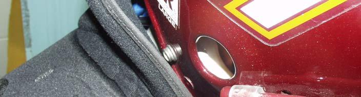
16 METHODS A 50% percentile male Hybrid-III anthropomorphic test dummy was utilized. The dummy was fitted with a standard set of Douglas model CP25 shoulder pads, and a Riddell VSR-4 helmet. Impacts were performed with this standard configuration, as well as with one of three accessory collars: the McDavid Cowboy Collar, a customdesigned and fitted collar worn by a Virginia Tech player called a Bullock Collar, and a prototype device called the Kerr Collar. Collars The Cowboy Collar is manufactured by McDavid. It features a molded polyethylene foam collar, and is designed to be laced into the shoulder pads. There is no other anchoring method other than the laces (Figure 4). The Kerr Collar is designed to be worn under the shoulder pads, and features ridges designed to contact the lower edge of the football helmet in an impact. There are rigid stabilizers mounted inside the ridges (Figure 5). The Bullock collar was designed by Dr. Richard Bullock, a head team physician for the Virginia Tech football team for many years. The Bullock Collar is custom-designed and fitted for each specific player. It features a high-density foam collar with a rigid plastic insert. It is attached with straps that are bolted to the shoulder pads (Figure 6). 8


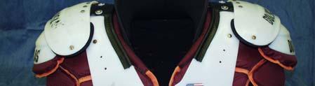
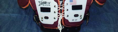


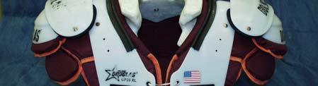


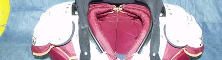

17 Figure 4: Cowboy Collar Figure 5: Kerr Collar Figure 6: Bullock Collar 9
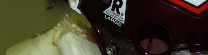
18 The collars, as well as the standard shoulder pads, were evaluated both in a normal state, and in a raised state, which was meant to simulate a player assuming a tackling posture, in which the shoulders are naturally raised in anticipation of an impact. For the standard shoulder pads and the Bullock Collar, foam blocks were inserted underneath the shoulder pads to raise them up until the bottom of the helmet was touching the pads. For the Cowboy Collar and the Kerr Collar, expandable polyurethane foam was poured into bags located under the collars in order to raise them until the collars were touching the bottom of the helmet. Instrumentation The impacts were performed with a pneumatic linear impactor (Figure 7). When activated, a solenoid opens a butterfly valve, which sends a blast of compressed air into a chamber. Inside this chamber is a piston, which is accelerated out of the chamber and pushes an impactor arm with a weight of 15 kg. The end of the impactor has a hemispherical nylon shell with high-density vinyl nitrile foam underneath. This impacting surface was designed to replicate the impacting characteristics of a typical football helmet, and is identical to the impacting surface used in the new proposed NOCSAE standard for football helmet testing (Pellman 2006). This impact surface is elastic, and with a minimal rest period between impacts (two minutes), its impact properties do not change over the course of testing. The impactor has a maximum velocity of 15 m/s. Velocities of 7.5 m/s and 11 m/s were used for this study. Impact velocities were controlled to within 3.4% error. These impact velocities were chosen 10


.")

19 based upon a review of the new proposed NOCSAE standard for helmet certification (Pellman 2006). Figure 7: Linear pneumatic impactor The dummy was fitted with three single-axis orthogonally mounted accelerometers in the center of gravity of the head, and three orthogonal angular rate sensors. Upper and lower six-axis load cells were also used. Chin strap load cells were attached to the chin strap of the helmet. The impactor was fitted with a three-axis load cell and accelerometer, as well as a light gate to record impact velocity. High-speed video was recorded of each impact using a Phantom color video camera operating at 1,000 frames per second (Figure 8). All data was filtered to CFC 180. The helmet was fitted onto the dummy using a helmet positioning tool that uses landmarks on the helmet and the dummy s face to position the helmet. The tool is aligned with the dummy s nose and the helmet is adjusted until the edge of the facemask is aligned with a line on the tool (Figure 9). The dummy was positioned relative to the impactor by aligning a target on the helmet with the center of the impactor (Figure 10). 11


20 With these tools, the positioning of the helmet on the dummy is consistent, as well as the positioning of the dummy relative to the impactor. Each of these can be controlled to within 3 degrees. Figure 8: Instrumentation setup Figure 9: Helmet positioning tool 12

.")

21 Figure 10: Center of impactor marker Impact Locations Three impact locations were used: a side location, which was located approximately on the Frankfurt plane directly on the side of the head a front location, which was located directly above the uppermost edge of the facemask and an axial loading location, which was chosen to create a situation in which the neck acts as a segmented column with a minimum of bending (Appendix B). The axial loading condition was located approximately halfway from the front position and a crown impact on the top of the head. The impact locations were marked on the helmet, and a helmet positioning tool was used to ensure that the helmet was positioned on the dummy head in the same fashion for each impact (Appendix B). The test matrix yielded a total of 48 impacts. 13


 2 3-100 Figure 11: Time traces for exemplar impact.")
22 RESULTS Data were collected for 48 impacts. For each impact, head acceleration and angular velocity, upper and lower neck loads and moments, impactor loads, and impact velocity was recorded, as well as high-speed video (Figure 11). Data can be found in Tables 1-4 and Appendix A. Figures A 19, A 20, and A 21 illustrate that impactor load and bending moments are independent of impact velocity Impactor Load Lower Neck Bending Moment Upper Neck Bending Moment 150 Force (N Moment (Nm Time (ms) Figure 11: Time traces for exemplar impact. Images correspond to first contact (1), peak lower neck bending moment (2), and peak upper neck bending moment (3). Side Impact Location 14
23 Results for the side impact location are presented. We are most concerned with the lower neck bending moment in the lateral direction, Mx. For the control situation with only the shoulder pads and helmet, the lower neck load cell recorded a peak moment of N m at the low speed impact, and N m for the high speed impact. The moments with the Cowboy Collar were virtually the same, with N m at the low speed and N m at the high speed. The Kerr Collar reduced the lateral bending moment slightly, providing N m at the low speed and N m at the high speed impacts. Finally, the Bullock Collar also reduced this moment, with N m and N m at the low and high speed impacts respectively (Figure 12). All shoulder pad/collar combinations performed better in the raised positions; the control configuration provided N m and N m in the low and high speed impacts. The Cowboy Collar, in the raised position, was able to reduce these moments to N m and N m for the low and high speed impacts. The Kerr and Bullock Collars had a smaller effect, with N m and N m for the low and high speeds for the Kerr, and N m and N m for the Bullock Collar (Figure 13). 15
24 Mx 7.5 m/s Mx 11 m/s Moment (Nm) No Collar Cowboy Collar Kerr Collar Bullock Collar 250 Figure 12: Side impact location, lower beck bending moment 200 Mx 7.5 m/s Mx 11 m/s Moment (Nm) No Collar Cowboy Collar Kerr Collar Bullock Collar Figure 13: Side impact location, raised shoulder pads, lower neck bending moment Front Impact Location In the front location, we examine the lower neck bending moment in the anteriorposterior direction, My. The control configuration provided lower neck bending moments of N m for the low speed and N m for the high speed impact. The Cowboy Collar provided a slight reduction in these forces for the low speed impact 16
25 with N m, but was the best performer in the high speed impact with N. The Kerr Collar provided a reduction in both tests with N m and N m in the low and high speed impacts, respectively. The Bullock Collar proved to be the best performer in the low speed impact at N m, and reduced the moment to N m in the high speed impact (Figure 14). It is interesting to note that these moment reductions at the lower neck generally correlate to higher moments in the anterior-posterior bending moment of the upper neck. The control configuration provided N m for the low speed impact and N m for the high speed impact. The Cowboy Collar raised these numbers to N m for the low speed impact, and provided the largest increase to N m for the high-speed impact. The Kerr Collar s tests resulted in N m and N m for the low and high speed impacts. The Bullock Collar performed similarly, with N m at the low speed impact and N m at the high speed impact (Figure 15) My 7.5 m/s My 11 m/s 200 Moment (Nm) No Collar Cowboy Collar Kerr Collar Bullock Collar Figure 14: Front impact location, lower neck bending moment 17
26 My 7.5 m/s My 11 m/s 120 Moment (Nm) No Collar Cowboy Collar Kerr Collar Bullock Collar Figure 15: Front impact location, upper neck bending moment Axial Loading Impact Location At the axial loading location, we examined the percent reduction of impactor load. The axial load at the lower neck load cell, Fz, is considered as a percentage of the impactor load. The control configuration s tests resulted in a 14.39% reduction of impact load for the low speed impact, and a 24.41% reduction for the high speed impact. The Cowboy Collar provided a larger load reduction, with 18.67% and 27.89% reductions at the low and high speeds respectively. The Kerr Collar proved to be the best performer, with a 23.23% reduction at the low speed impact and a 28.78% reduction at the high speed impact. The Bullock Collar also provided a larger percent reduction, with a 16.01% reduction at the low speed, and a 22.38% reduction at the high speed (Figure 16). When the collars and shoulder pads were raised, the results differed slightly. The control configuration provided a 16.38% reduction at the low speed, and a 28.18% reduction at the high speed. The Cowboy Collar performed worse than the control, with 11.31% and 23.41% reductions at the low and high speeds. The Kerr Collar provided a 18
27 larger percent reduction in both tests, with 28.25% and 32.73% reductions at the low and high speeds. The Bullock Collar provided a small reduction at the low speed with 17.97%, but performed worse than the control at the high speed, with 26.46% reduction (Figure 17) m/s 11 m/s Reduction of Impactor Load (%) No Collar Cowboy Collar Kerr Collar Bullock Collar Figure 16: Axial loading impact location, percent reduction of impactor load m/s 11 m/s Reduction of Impactor Load (%) No Collar Cowboy Collar Kerr Collar Bullock Collar Figure 17: Axial loading impact location, raised shoulder pads, percent reduction of impactor load 19
28 Test Number Impact Location Table 1: Data from impact tests (page 1 of 4) Shoulder Target Velocity Position (m/s) Collar Type Actual Velocity (m/s) Percent Error neck34 side No Collar normal neck35 side No Collar normal neck36 front No Collar normal neck37 front No Collar normal neck38 AL No Collar normal neck39 AL No Collar normal neck40 AL No Collar raised neck41 AL No Collar raised neck42 front No Collar raised neck43 front No Collar raised neck44 side No Collar raised neck45 side No Collar raised neck46 side Cowboy Colnormal neck47 side Cowboy Colnormal neck48 front Cowboy Colnormal neck49 front Cowboy Colnormal neck50 AL Cowboy Colnormal neck51 AL Cowboy Colnormal neck52 AL Cowboy Colraised neck53 AL Cowboy Colraised neck54 front Cowboy Colraised neck55 front Cowboy Colraised neck56 side Cowboy Colraised neck57 side Cowboy Colraised neck58 side Kerr Collar normal neck59 side Kerr Collar normal neck60 front Kerr Collar normal neck61 front Kerr Collar normal neck62 AL Kerr Collar normal neck63 AL Kerr Collar normal neck64 AL Kerr Collar raised neck65 AL Kerr Collar raised neck66 front Kerr Collar raised neck67 front Kerr Collar raised neck68 side Kerr Collar raised neck69 side Kerr Collar raised neck70 side Bullock Col normal neck71 side Bullock Col normal neck72 front Bullock Col normal neck73 front Bullock Col normal neck74 AL Bullock Col normal neck75 AL Bullock Col normal neck76 AL Bullock Col raised neck77 AL Bullock Col raised neck78 front Bullock Col raised neck79 front Bullock Col raised neck80 side Bullock Col raised neck81 side Bullock Col raised
29 Table 2: Data from impact tests (page 2 of 4) Lower Neck Loads (N) Lower Neck Moments (Nm) Test Number Fx Fy Fz Res Mx My Mz Res neck neck neck neck neck neck neck neck neck neck neck neck neck neck neck neck neck neck neck neck neck neck neck neck neck neck neck neck neck neck neck neck neck neck neck neck neck neck neck neck neck neck neck neck neck neck neck neck
30 Table 3: Data from impact tests (page 3 of 4) Upper Neck Loads (N) Upper Neck Moments (Nm) Test Number Fx Fy Fz Res Mx My Mz Res neck neck neck neck neck neck neck neck neck neck neck neck neck neck neck neck neck neck neck neck neck neck neck neck neck neck neck neck neck neck neck neck neck neck neck neck neck neck neck neck neck neck neck neck neck neck neck neck
31 Test Number Table 4: Data from impact tests (page 4 of 4) Head Acceleration Lower Neck Imactor Load (N) (g) Load Fz (N) Nij Percent Reduction of Impact Force (%) neck neck neck neck neck neck neck neck neck neck neck neck neck neck neck neck neck neck neck neck neck neck neck neck neck neck neck neck neck neck neck neck neck neck neck neck neck neck neck neck neck neck neck neck neck neck neck neck
32 DISCUSSION We predict injury due to flexion in many of the high-speed impacts; the majority of these yielded lower neck bending moments that exceed 190 N m, which is the injury assessment reference value for flexion injury to the neck from NHTSA (Eppinger 2000). In addition, all of the axial loading tests resulted in higher compression loads than the stated 4000 N limit. The collars had very little effect on head acceleration, but we also predict concussion for many of the high-speed impacts (Figure A 13 - Figure A 18) (Eppinger 2000). In the front impact location, the Cowboy Collar, and to a lesser extent the Kerr and Bullock collars, reduced the lower neck bending moment. However, there was a corresponding increase of the upper neck bending moment for all collars. Upon inspection of the high-speed video, it is apparent that the collars are changing the point about which the head rotates with respect to the torso. With no collar, the head is free to rotate about the base of the neck. However, with a collar, the pivot is raised up to the point at which the collar contacts the helmet, thus transferring these forces into the upper neck (Figure 18). 24
.")
33 Figure 18: Pivot point with no collar (left), and with Cowboy Collar (right) Biofidelity of Model Developing a model of the neck that is biofidelic is a monumental challenge. The anatomy of the cervical spine is quite complicated; the vertebrae and their articulation with each other are intricate (Figure 19). In addition, many small muscle groups provide support and strength of the neck. Figure 19: Cervical spine, anterior view (left) and lateral view (center), and Hybrid-III neck assembly (right) This complex anatomy and musculature presents a unique challenge in creating a mechanical replica that will respond as a human neck would in an impact. The current 25
34 state of the art in impact testing is the Hybrid-III anthropomorphic test dummy, which was designed for automotive testing. In the Hybrid-III, the neck is simulated with a stainless steel and high-density rubber neck assembly (Figure 19). While the Hybrid-III neck responds similarly to a human s in a frontal crash test, it cannot replicate the complicated kinematics that occur during such impacts, and thus is an imperfect model. Impact Velocities Impact velocities for this test were chosen with respect to prior research performed at the Virginia Tech-Wake Forest Center for Injury Biomechanics dealing with concussions, and with consideration of the new proposed NOCSAE standard for helmet testing (Pellman 2006). Upon review of the test results, it has been determined that further testing is needed at lower impact velocities that are similar to injurious impacts in the field with respect to neck injuries. Stingers often occur from glancing or indirect blows that involve low relative impact velocities. Perhaps lower velocities will illustrate differences in the collar s abilities to limit loads and moments in impacts. Future Testing A second test series is planned with lower impact velocities. Impact velocities will be chosen to more accurately approximate injurious impacts as they occur in the field. This test series will also incorporate an angular rate sensor array on the Hybrid- III s body, in order to calculate the angle of rotation of the head during an impact. 26
35 CONCLUSIONS Side Impact Location At the side impact location, it was apparent that none of the collars had sufficient padding to reduce neck loads. Although the Kerr and Bullock collars did reduce the lower neck bending moment slightly, this effect was minimal. When the shoulder pads and collars were raised, the collars were allowed to interact with the helmet to a larger degree and thus were more effective at limiting loads; however, the shoulder pads alone also performed this function, albeit to a lesser extent. It is apparent that there is a lack of padding at the side position of many collars on the market today. Producing a collar that provides support and protection without hindering range of motion is a challenge. Front Impact Location At the front impact location, the collars reduced the bending moment at the lower neck, with the Cowboy Collar providing the largest reduction. However, this reduction was always coupled with a corresponding rise the bending moment at the upper neck. Upon analysis of the high-speed video, it appears that the collars are providing a point of rotation that is higher than the control configuration; that is, the collar acts like a fulcrum about which the head rotates. This might lead to a higher risk of injury at the upper neck. When the shoulder pads are raised, this phenomenon is eliminated and the collars are effective at limiting the upper and lower neck bending moments. However, protection while still allowing a free range of motion remains important. 27
36 Axial Loading Impact Location The Kerr Collar proved to be the most efficient collar at providing a reduction of impactor load in the axial loading impact location. The Cowboy Collar and the Bullock Collar also provided a larger percent reduction of load compared to the control configuration; however, when the shoulder pads were raised, the Cowboy and Bullock collars fared worse than the control configuration. Upon analysis of the dummy kinematics, it appears that the collars hold the head and neck in place and force the neck into an axial compression situation. The Kerr Collar provides an even larger percent reduction with the shoulder pads raised. In summary, all of the collars provided a reduction of loads or moments at some impact locations. The Kerr and Bullock collars provided the largest reduction in bending moment at the side impact location in the normal configuration, while all of the collars reduced this moment in the raised position. The Cowboy Collar, at the raised position, was effective at limiting upper and lower neck loads in the front impact location. The Kerr Collar was effective at reducing the impact load in the axial loading condition. However, some collars allowed larger loads and moments than the shoulder pads alone. The upper neck loads were higher for all collars in the normal position at the front impact location. In addition, the Cowboy and Bullock collars did not reduce the impactor load as much as the control configuration in the raised axial loading impact location. More investigation is needed to determine if the improper use of these collars will increase the risk of injury in some types of impacts. 28
37 REFERENCES Andrish, J.T., Bergfeld, J.A., and Romo, L. (1977) A method for the management of cervical injuries in football. A preliminary report. American Journal of Sports Medicine. 5(2): Carter, D.R., and Frankel, V.H. (1980) Biomechanics of hyperextension injuries to the cervical spine in football. American Journal of Sports Medicine. 8(5): Castro, F.P., Ricciardi, J., Brunet, M.E., Busch, M.T., and Whitecloud, T.S. (1997) Stingers, the Torg ration, and the cervical spine. American Journal of Sports Medicine. 25(5): Clancy, W.G., Brand, R.L., and Bergfield, J.A. (1977) Upper trunk brachial plexus in juries in contact sports. American Journal of Sports Medicine. 5: Duma, S.M., Crandall, J.R., Rudd, R.W., and Kent, R.W. (2003) Small female head and neck interaction with a deploying side airbag. Accident Analysis and Prevention. 35: Duma, S.M., Manoogian, S.J., and Bussone, W.R. (2005) Analysis of real-time head accelerations in collegiate football players. Clinical Journal of Sports Medicine. 15(1): 3-8. Gorden, J.A., Straub, J.S., Swanik, C.B., and Swanik, K.A. (2003) Effects of football collars on cervical hyperextension and lateral flexion. Journal of Athletic Training. 38(3):
38 Hovis, W.D., and Limbird, T.J. (1994) An evaluation of cervical orthoses in limiting hyperextension and lateral flexion in football. Medicine and Science in Sports and Exercise. 26(7): Markey, K.L., di Benedetto, M., and Curl, W.W. (1993) Upper trunk brachial plexopathy: the stinger syndrome. 21(5): Meyers, S.A., Schulte, K.R., Callaghan, J.J., Albright, J.B., Powell, J.W., Crowley, E.T., and El-Khoury, G.Y. (1994) Cervical spinal stenosis and stingers in collegiate football players. American Journal of Sports Medicine. 22(2): Pellman, E.J., Viano, D.C., Tucker, A.M., and Casson, I.R. (2003) Concussion in professional football: location and direction of helmet impacts part 2. Neurosurgery. 53(6): Pellman, E.J., Viano, D.C., Tucker, A.M., Casson, I.R., and Waeckerle, J.F. (2003) Concussion in Professional Football: Reconstruction of game impacts and injuries. Neurosurgery. 53(4): Pellman, E.J., Viano, D.C., Withnall, C., Bir, C.A., and Halstead, P.D. (2006) Concussion in professional football: helmet testing to assess impact performance part 11. Neurosurgery. 58(1): Sallis, R.E., Jones, K., and Knopp, W. (1992) Burners: offensive strategy for an underreported injury. The Physician and Sports Medicine. 20(11): Speer, K.P., and Bassett, F.H. (1990) The prolonged burner syndrome. American Journal of Sports Medicine. 18(6):
39 Torg, J.S., Begso, J.J., O Neill, M.J., and Sennett, B. (1990) The epidemiologic, pathologic, biomechanical, and cinematographic analysis of football-induced cervical spine trauma. American Journal of Sports Medicine. 18(1): Torg, J.S., Sennett, B., Pavlov, H., Leventhal, M.R., and Glasgow, S.G. (1993) Spear tackler s spine: an entity precluding participation in tackle football and collision activities that expose the cervical spine to axial energy inputs. American Journal of Sports Medicine. 21(5): Virgin, H. (1980) Cineradiographic study of football helmets and the cervical spine. American Journal of Sports Medicine. 8(5):
40 APPENDIX A: Impact Data Mx 7.5 m/s Mx 11 m/s 60 Moment (Nm) No Collar Cowboy Collar Kerr Collar Bullock Collar Figure A 1: Side impact location, upper neck bending moment Mx 7.5 m/s Mx 11 m/s Moment (Nm) No Collar Cowboy Collar Kerr Collar Bullock Collar Figure A 2: Side impact location, raised shoulder pads, upper neck bending moment 32
41 Fy 7.5 m/s Fy 11 m/s Force (N) No Collar Cowboy Collar Kerr Collar Bullock Collar Figure A 3: Side impact location, upper neck shear force Mx 7.5 m/s Mx 11 m/s Force (N) No Collar Cowboy Collar Kerr Collar Bullock Collar Figure A 4: Side impact location, raised shoulder pads, upper neck shear force 33
42 m/s 11 m/s 0.40 Nij No Collar Cowboy Collar Kerr Collar Bullock Collar Figure A 5: Side impact location, modified Nij m/s 11 m/s 0.4 Nij No Collar Cowboy Collar Kerr Collar Bullock Collar Figure A 6: Side impact location, raised shoulder pads, modified Nij 34
43 My 7.5 m/s My 11 m/s 200 Moment (Nm) No Collar Cowboy Collar Kerr Collar Bullock Collar Figure A 7: Front impact location, raised shoulder pads, lower neck bending moment My 7.5 m/s My 11 m/s 120 Moment (Nm) No Collar Cowboy Collar Kerr Collar Bullock Collar Figure A 8: Front impact location, raised shoulder pads, upper neck bending moment 35
44 Fx 7.5 m/s Fx 11 m/s 1000 Force (N) No Collar Cowboy Collar Kerr Collar Bullock Collar Figure A 9: Front impact location, upper neck shear force Fx 7.5 m/s Fx 11 m/s 1000 Force (N) No Collar Cowboy Collar Kerr Collar Bullock Collar Figure A 10: Front impact location, raised shoulder pads, upper neck shear force 36
45 Fz 7.5 m/s Fz 11 m/s Force (N) No Collar Cowboy Collar Kerr Collar Bullock Collar Figure A 11: Axial loading position, lower neck axial compression force Fz 7.5 m/s Fz 11 m/s Force (N) No Collar Cowboy Collar Kerr Collar Bullock Collar Figure A 12: Axial loading position, raised shoulder pads, lower neck axial compression force 37
46 m/s 11 m/s Acceleration (g) No Collar Cowboy Collar Kerr Collar Bullock Collar Figure A 13: Side impact location, peak head acceleration m/s 11 m/s 120 Acceleration (g) No Collar Cowboy Collar Kerr Collar Bullock Collar Figure A 14: Side impact location, raised shoulder pads, peak head acceleration 38
47 m/s 11 m/s Acceleration (g) No Collar Cowboy Collar Kerr Collar Bullock Collar Figure A 15: Front impact location, peak head acceleration m/s 11 m/s Acceleration (g) No Collar Cowboy Collar Kerr Collar Bullock Collar Figure A 16: Front impact location, raised shoulder pads, peak head acceleration 39
48 m/s 11 m/s Acceleration (g) No Collar Cowboy Collar Kerr Collar Bullock Collar Figure A 17: Axial loading impact location, peak head acceleration m/s 11 m/s 120 Acceleration (g) No Collar Cowboy Collar Kerr Collar Bullock Collar Figure A 18: Axial loading impact location, raised shoulder pads, peak head acceleration 40
49 Impactor Load (N) Front and Axial Loading Impact Locations R 2 = Side Impact Location Impact Velocity (m/s) Figure A 19: Impact velocity versus impactor load, low impact velocity Impactor Load (N) Front and Axial Loading Impact Locations R 2 = Side Impact Location Impact Velocity (m/s) Figure A 20: Impact velocity versus impactor load, high impact velocity 41
50 148 Lower Neck Bending Moment (Nm) R 2 = Impact velocity (m/s) Figure A 21: Impact velocity versus lower neck bending moment, side impact location, low impact velocity 42


 43")
51 APPENDIX B: Test setup Figure B 1: Side impact location (front view) Figure B 2: Side impact location (oblique view) 43

")

 44")
52 Figure B 3: Side impact location (front view) Figure B 4: Front impact location (oblique view) 44


 45")

53 Figure B 5: Axial loading impact location (front view) Figure B 6: Axial loading impact location (oblique view) 45


54 Figure B 7: Cowboy Collar in raised position Figure B 8: Cowboy Collar in raised position (closeup) 46


55 Figure B 9: Kerr collar in normal position Figure B 10: Kerr collar in raised position 47
Head Impacts in Hockey and Youth Football: Biomechanical Response and Helmet Padding Characteristics. Anna M. MacAlister
 Head Impacts in Hockey and Youth Football: Biomechanical Response and Helmet Padding Characteristics Anna M. MacAlister Thesis submitted to the faculty of the Virginia Polytechnic Institute and State University
Sports-related concussions are a growing public. Biomechanical performance of leather and modern football helmets. Technical note
 See the corresponding editorial in this issue, pp 803 804. J Neurosurg 119:805 809, 2013 AANS, 2013 Biomechanical performance of leather and modern football helmets Technical note Steven Rowson, Ph.D.,
A Method for Assessing the Overall Impact Performance of Riot Helmets
 246 JOURNAL OF APPLIED BIOMECHANICS, 2003, 19, 246-254 2003 by Human Kinetics Publishers, Inc. A Method for Assessing the Overall Impact Performance of Riot Helmets Jean-Philippe Dionne, Ismail El Maach,
Quantifying the effect of the facemask on helmet performance
 Original Article Quantifying the effect of the facemask on helmet performance Proc IMechE Part P: J Sports Engineering and Technology 2018, Vol. 232(2) 94 101 Ó IMechE 2017 Reprints and permissions: sagepub.co.uk/journalspermissions.nav
DEVELOPMENT OF A PEDESTRIAN LOWER EXTREMITY PROTECTION CAR USING A BIOFIDELIC FLEXIBLE PEDESTRIAN LEGFORM IMPACTOR
 DEVELOPMENT OF A PEDESTRIAN LOWER EXTREMITY PROTECTION CAR USING A BIOFIDELIC FLEXIBLE PEDESTRIAN LEGFORM IMPACTOR Atsuhiro Konosu, Takahiro Issiki Japan Automobile Research Institute (JARI) Masaaki Tanahashi
Subject Index. STPIO50-EB/Sep Boot construction and blade fit, 135 Brain injury impact testing and,
 STPIO50-EB/Sep. 1989 Subject Index A Acceleration drop height, multidirectional, 257 helmet impact testing, 244, 248-249 Accelerometer, 270 Adolescent players, physique differences in, 90-93 Aging of equipment,
20XX. Bicycle Helmets for Children 2017 tested by Folksam
 20XX Bicycle Helmets for Children 2017 tested by Folksam This is why we test bicycle helmets Every day three cyclists in Sweden sustain head injuries, which are some of the most severe injuries a cyclist
Latest FE Model Development of THOR-50M Crash Test Dummy
 Latest FE Model Development of THOR-50M Crash Test Dummy Ismail Maatouki*, Stephen Fu**, Zaifei Zhou**, *Humanetics Europe GmbH, Heidelberg, Germany **Humanetics Innovative Solutions, Inc. Farmington Hills,
Ankle biomechanics demonstrates excessive and prolonged time to peak rearfoot eversion (see Foot Complex graph). We would not necessarily expect
. We would not necessarily expect") Case Study #1 The first case study is a runner presenting with bilateral shin splints with pain and tenderness along the medial aspect of the tibia. The symptoms have increased significantly over the last
Case Study #1 The first case study is a runner presenting with bilateral shin splints with pain and tenderness along the medial aspect of the tibia. The symptoms have increased significantly over the last
Analysis of Padding Recovery Time for Sports Helmets
 Analysis of Padding Recovery Time for Sports Helmets Undergraduate Honors Thesis Presented in Partial Fulfillment of the Requirements for Graduation with Research Distinction in the Department of Mechanical
Development of an end-effector to simulate the foot to ball interaction of an instep kick in soccer
 Available online at www.sciencedirect.com Procedia Engineering 34 (2012 ) 284 289 9 th Conference of the International Sports Engineering Association (ISEA) Development of an end-effector to simulate the
Summary of Guardian Protective Cover Impact Testing April 5, 2011
 Summary of Protective Cover Impact Testing April 5, 11 Attached is the graphical data and analysis of representative impacts that occurred during testing from our tri-axial accelerometer. We used the DTS
Auto Rickshaw Impacts with Pedestrians: A Computational Analysis of Post-Collision Kinematics and Injury Mechanics
 Auto Rickshaw Impacts with Pedestrians: A Computational Analysis of Post-Collision Kinematics and Injury Mechanics A. J. Al-Graitti, G. A. Khalid, P. Berthelson, A. Mason-Jones, R. Prabhu, M. D. Jones
CALIBRATION AND VERIFICATION OF DETAILED HYBRID III 50 TH PERCENTILE MALE ANTHROPOMORPHIC TEST DEVICE (ATD) BASED ON EXTENSIVE MINE BLAST TESTS
 BASED ON EXTENSIVE MINE BLAST TESTS") 2017 NDIA GROUND VEHICLE SYSTEMS ENGINEERING AND TECHNOLOGY SYMPOSIUM MODELING & SIMULATION, TESTING AND VALIDATION (MSTV) TECHNICAL SESSION AUGUST 8-10, 2017 - NOVI, MICHIGAN CALIBRATION AND VERIFICATION
2017 NDIA GROUND VEHICLE SYSTEMS ENGINEERING AND TECHNOLOGY SYMPOSIUM MODELING & SIMULATION, TESTING AND VALIDATION (MSTV) TECHNICAL SESSION AUGUST 8-10, 2017 - NOVI, MICHIGAN CALIBRATION AND VERIFICATION
HYBRID III DUMMY NECK RESPONSE TO AIR BAG LOADING. Venkatesh Agaram, Jian Kang, Guy Nusholtz and Gregory Kostyniuk DaimlerChrysler USA Paper No.
 HYBRID III DUMMY NECK RESPONSE TO AIR BAG LOADING Venkatesh Agaram, Jian Kang, Guy Nusholtz and Gregory Kostyniuk DaimlerChrysler USA Paper No.469 ABSTRACT This paper discusses issues related to the Hybrid
Linear and Angular Head Acceleration Measurements in Collegiate Football
 Steven Rowson Center for Injury Biomechanics, Virginia Tech-Wake Forest, Blacksburg, VA 24061 Gunnar Brolinson Edward Via Virginia College of Osteopathic Medicine, Blacksburg, VA 24061 Mike Goforth Dave
WHAT IS MIPS? AND HOW DOES IT WORK?
 WHAT IS MIPS? AND HOW DOES IT WORK? In a helmet with MIPS Brain Protection System (BPS) the shell and the liner are separated by a Low Friction Layer. When a helmet with MIPS Brain Protection System is
A Numerical Investigation of Human Biomechanical Response under Vertical Loading Using Dummy and Human Finite Element Models
 A Numerical Investigation of Human Biomechanical Response under Vertical Loading Using Dummy and Human Finite Element Models Costin D. Untaroiu, Jacob Putnam Virginia Tech, Blacksburg, VA, USA Abstract
MADYMO human models for Euro NCAP pedestrian safety assessment
 MADYMO human models for Euro NCAP pedestrian safety assessment Contents Introduction MADYMO Human Models Virtual testing in Euro NCAP Active bonnet safety performance Application of human body models MADYMO
 WINSTON SALEM/FORYTH COUNTY SCHOOLS SAFETY LIST FOR FOOTBALL PLAYERS Football is a contact sport and injuries will occur. The coaches working in our program are well qualified, professional people. Fundamentals
EUROPEAN NEW CAR ASSESSMENT PROGRAMME (Euro NCAP) SLED TEST PROCEDURE FOR ASSESSING KNEE IMPACT AREAS
 SLED TEST PROCEDURE FOR ASSESSING KNEE IMPACT AREAS") www.euroncap.com EUROPEAN NEW CAR ASSESSMENT PROGRAMME (Euro NCAP) SLED TEST PROCEDURE FOR ASSESSING KNEE IMPACT AREAS Version 1.0a December 2004 Sled Test Procedure for Assessing Knee Impact Areas (V1.0a)
www.euroncap.com EUROPEAN NEW CAR ASSESSMENT PROGRAMME (Euro NCAP) SLED TEST PROCEDURE FOR ASSESSING KNEE IMPACT AREAS Version 1.0a December 2004 Sled Test Procedure for Assessing Knee Impact Areas (V1.0a)
Study & Manipulative Training Guide
 Study Manipulative Training Guide What is the XCOLLAR? The XCollar is a complete Cervical Spine Splinting System designed especially for EMS. It ensures the highest level of patient safety while significantly
STAR Methodology for Bicycle Helmets
 Laboratory Tests Virginia Tech Helmet Lab 343 Kelly Hall 325 Stanger St Blacksburg, Virginia 24061 P: (540) 231-8254 rowson@vt.edu STAR Methodology for Bicycle Helmets Megan L. Bland, Craig McNally, and
Chapter 1 - Injury overview Chapter 2 - Fit for Running Assessment Chapter 3 - Soft Tissue Mobilization... 21
 Table of Contents Introduction Chapter 1 - Injury overview... 6 Chapter 2 - Fit for Running Assessment... 13 Chapter 3 - Soft Tissue Mobilization... 21 Chapter 4 - Dynamic Warm-up... 28 Chapter 5 - Strengthening...
Restraint Systems for Infants with Special Needs
 TEST METHOD 213.5 Restraint Systems for Infants with Special Needs Revised: Issued: May 2012R October 1997 (Ce document est aussi disponible en français) Table of Contents 1. Introduction... 1 2. Test
GROUND REACTION FORCE DOMINANT VERSUS NON-DOMINANT SINGLE LEG STEP OFF
 GROUND REACTION FORCE DOMINANT VERSUS NON-DOMINANT SINGLE LEG STEP OFF Sara Gharabaghli, Rebecca Krogstad, Sara Lynch, Sofia Saavedra, and Tamara Wright California State University, San Marcos, San Marcos,
Use of Throw Distances of Pedestrians and Bicyclists as Part of a Scientific Accident Reconstruction Method 1
 contents Introduction xi CHAPTER 1 Use of Throw Distances of Pedestrians and Bicyclists as Part of a Scientific Accident Reconstruction Method 1 Introduction 2 Basis of Speed Calculation 2 New Results
A Comparison of Peak Linear and Angular Headform Accelerations Using Ice Hockey Helmets
 Journal of ASTM International, Vol. 6, No. 1 Paper ID JAI101877 Available online at www.astm.org P. Rousseau, 1 A. Post, 1 and T. B. Hoshizaki 1 A Comparison of Peak Linear and Angular Headform Accelerations
Serve the only stroke in which the player has full control over its outcome. Bahamonde (2000) The higher the velocity, the smaller the margin of
 The higher the velocity, the smaller the margin of") Lower Extremity Performance of Tennis Serve Reporter: Chin-Fu Hsu Adviser: Lin-Hwa Wang OUTLINE Introduction Kinetic Chain Serve Types Lower Extremity Movement Summary Future Work INTRODUCTION Serve the
Lower Extremity Performance of Tennis Serve Reporter: Chin-Fu Hsu Adviser: Lin-Hwa Wang OUTLINE Introduction Kinetic Chain Serve Types Lower Extremity Movement Summary Future Work INTRODUCTION Serve the
AndrewsREF.org 1020 Gulf Breeze Parkway, Gulf Breeze, FL (850)
") The Andrews Research and Education Foundation are proud to present the results of testing on the FaceLoc quick release system that has been completed in conjunction with the sponsoring company. Introduction:
The Andrews Research and Education Foundation are proud to present the results of testing on the FaceLoc quick release system that has been completed in conjunction with the sponsoring company. Introduction:
Protection against Impact with the Ground Using Wearable Airbags
 Industrial Health 2008, 46, 59 65 Original Article Protection against Impact with the Ground Using Wearable Airbags Kiyoshi FUKAYA 1 * and Mitsuya UCHIDA 2 1 National Institute of Occupational Safety and
The Effect of a Seven Week Exercise Program on Golf Swing Performance and Musculoskeletal Screening Scores
 The Effect of a Seven Week Exercise Program on Golf Swing Performance and Musculoskeletal Screening Scores 2017 Mico Hannes Olivier Bachelor of Sport Science Faculty of Health Sciences and Medicine Bond
A QUALITATIVE ANALYSIS OF THE HIGH RACQUET POSITION BACKHAND DRIVE OF AN ELITE RACQUETBALL PLAYER
 A QUALITATIVE ANALYSIS OF THE HIGH RACQUET POSITION BACKHAND DRIVE OF AN ELITE RACQUETBALL PLAYER John R. Stevenson Wayne P. Hollander Since 1950, when Joe Sobek put strings on his paddleball paddle, the
Snowsport Helmets: The Good and Bad
 Snowsport Helmets: The Good and Bad Irving Scher, PhD, PE Jasper Shealy, PhD Inherent Risks in Snow Sports Head Injuries in Snow Sports 4% to 12% of all injuries Potential outcomes: minor to severe Death
PWG-S. Application example. Pneumatic 2-Finger Angular Gripper Universal Gripper. Sizes. Gripping moment 5.98 Nm Nm. Weight 0.21 kg 1.
 PWG-S Sizes 40 80 Weight 0.21 kg 1.2 kg Gripping moment 5.98 Nm 50.82 Nm Angle per jaw 20 Workpiece weight 1.1 kg 4.8 kg Application example Rotating/gripping combination for flexible handling of sheet
WorldSID 5% Dummy Model Development in Cooperation with German Automotive Industry
 14 th International LS-DYNA Users Conference Session: Occupant Safety WorldSID 5% Dummy Model Development in Cooperation with German Automotive Industry Sebastian Stahlschmidt, George Dumitru, Yupeng Huang,
REPORT. A comparative study of the mechanical and biomechanical behaviour of natural turf and hybrid turf for the practise of sports
 REPORT A comparative study of the mechanical and biomechanical behaviour of natural turf and hybrid turf for the practise of sports Addressed to: PSF - PALAU TURF Date: May 2015 Table of Contents SHEET
Opus: University of Bath Online Publication Store
 Seminati, E., Cazzola, D., Preatoni, E. and Trewartha, G. (2015) Evaluation of tackling biomechanics in rugby:video incident analysis and experimental set up. In: XXXIII International Conference on Biomechanics
Hands should be positioned at approximately shoulder width with a comfortable grip.
 The Basics Bike Fit The bicycle should be adapted to fit your body and not the other way around. There are many styles of bicycles that can be modified to meet your needs. Weight distribution should be
6. EXPERIMENTAL METHOD. A primary result of the current research effort is the design of an experimental
 6. EXPERIMENTAL METHOD 6.1 Introduction A primary result of the current research effort is the design of an experimental setup that can simulate the interaction of a windmill with a vortex wake and record
Analysis of Gait Characteristics Changes in Normal Walking and Fast Walking Of the Elderly People
 IOSR Journal of Engineering (IOSRJEN) ISSN (e): 2250-3021, ISSN (p): 2278-8719 Vol. 08, Issue 7 (July. 2018), V (V) 34-41 www.iosrjen.org Analysis of Gait Characteristics Changes in and Of the Elderly
Artifacts Due to Filtering Mismatch in Drop Landing Moment Data
 Camenga et al. UW-L Journal of Undergraduate Research XVI (213) Artifacts Due to Filtering Mismatch in Drop Landing Moment Data Elizabeth T. Camenga, Casey J. Rutten, Brendan D. Gould, Jillian T. Asmus,
First Recorded Automobile Race. PARIS to ROUEN, FRANCE July 22, miles
 First Recorded Automobile Race PARIS to ROUEN, FRANCE July 22, 1894 79 miles Early Days No attention paid to safety Post prize money and someone would risk his life for it Deaths were numerous Second
Dix 1 COMPARISON OF THE HARMONIZED HYBRID III 5 TH FEMALE DUMMY CHEST RESPONSE TO THE FTSS AND DENTON DUMMIES
 COMPARISON OF THE HARMONIZED HYBRID III 5 TH FEMALE DUMMY CHEST RESPONSE TO THE FTSS AND DENTON DUMMIES Jeff, Dix Nissan Technical Center North America United States of America Amanda, Bukhtia Nissan Technical
Body Stabilization of PDW toward Humanoid Walking
 Body Stabilization of PDW toward Humanoid Walking Masaki Haruna, Masaki Ogino, Koh Hosoda, Minoru Asada Dept. of Adaptive Machine Systems, Osaka University, Suita, Osaka, 565-0871, Japan ABSTRACT Passive
An investigation of kinematic and kinetic variables for the description of prosthetic gait using the ENOCH system
 An investigation of kinematic and kinetic variables for the description of prosthetic gait using the ENOCH system K. OBERG and H. LANSHAMMAR* Amputee Training and Research Unit, University Hospital, Fack,
PROPER PITCHING MECHANICS
 PROPER PITCHING MECHANICS While each pitcher is a different person and can display some individuality in his mechanics, everyone has similar anatomy (the same muscles, bones and ligaments in the same locations)
Effect of Pedestrian Buck Contact Area and Force-Deflection Property on Pedestrian Pelvis and Lower Limb Injuries
 IRC-12-26 IRCOBI Conference 212 Effect of Pedestrian Buck Contact Area and Force-Deflection Property on Pedestrian Pelvis and Lower Limb Injuries Miwako Ikeda 1, Shunji Suzuki 1, Yukou Takahashi 1, Shinsuke
HRC adjustable pneumatic swing-phase control knee
 HRC adjustable pneumatic swing-phase control knee S. NAKAMURA and S. SAWAMURA Hyogo Rehabilitation Centre, Kobe, Japan Abstract Since 1972 the Hyogo Rehabilitation Centre has been developing a variable-resistance-type
**INJURY OR DEATH MAY OCCUR IF THESE INSTRUCTIONS ARE NOT FOLLOWED**
 **INJURY OR DEATH MAY OCCUR IF THESE INSTRUCTIONS ARE NOT FOLLOWED** 4 MIN STERNUM STRAP MUST SIT AT LEAST 4 BELOW YOUR NECKLINE. ALL LATCHES MUST BE SECURE. HARNESS, SHOULDER AND LAP STRAPS MUST BE TIGHTENED
A Biomechanical Approach to Javelin. Blake Vajgrt. Concordia University. December 5 th, 2012
 A Biomechanical Approach to Javelin Blake Vajgrt Concordia University December 5 th, 2012 The Biomechanical Approach to Javelin 2 The Biomechanical Approach to Javelin Javelin is one of the four throwing
Examination of Human Body Mass Influence on Pedestrian Pelvis Injury Prediction Using a Human FE Model
 IRC-2 IRCOBI Conference 22 Examination of Human Body Mass Influence on Pedestrian Pelvis Injury Prediction Using a Human FE Model Yasuaki Gunji, Masayoshi Okamoto, Yukou Takahashi Abstract This research
World Forum for Harmonization of Vehicle Regulations (WP.29)
") Distr. GENERAL TRANS/WP.29/GRSP/2002/11 9 April 2002 ENGLISH ONLY ECONOMIC COMISSION FOR EUROPE INLAND TRANSPORT COMMITTEE World Forum for Harmonization of Vehicle Regulations (WP.29) Working Party on
Distr. GENERAL TRANS/WP.29/GRSP/2002/11 9 April 2002 ENGLISH ONLY ECONOMIC COMISSION FOR EUROPE INLAND TRANSPORT COMMITTEE World Forum for Harmonization of Vehicle Regulations (WP.29) Working Party on
APPROACH RUN VELOCITIES OF FEMALE POLE VAULTERS
 APPROACH RUN VELOCITIES OF FEMALE POLE VAULTERS Peter M. McGinnis, Physical Education Department, SUNY College at Cortland, Cortland, New York INTRODUCTION Running speed is an important determinant of
SIMULTANEOUS RECORDINGS OF VELOCITY AND VIDEO DURING SWIMMING
 Portuguese Journal of Sport Sciences. 6:supl. 2, 32-35, 2006 SIMULTANEOUS RECORDINGS OF VELOCITY AND VIDEO DURING SWIMMING Albert B. Craig 1, Budd Termin2, and David R. Pendergast 2 1University of Rochester,
Restraint Systems for Disabled Persons
 TEST METHOD 213.3 Restraint Systems for Disabled Persons Revised: Issued : May 2012R June 1, 1987 (Ce document est aussi disponible en français) Table of Contents 1. Introduction... 1 2. Test Devices to
Supporting Information Appendix
 Supporting Information Appendix Chang et al. 10.1073/pnas.XXXXXXXXXX Chang et al. 10.1073/pnas.XXXXXXXXXX 1 of 7 Fig. S1. (a) The neck length of the CT-scanned Northern Gannet and Brown Booby was determined
Biomechanics and Models of Locomotion
 Physics-Based Models for People Tracking: Biomechanics and Models of Locomotion Marcus Brubaker 1 Leonid Sigal 1,2 David J Fleet 1 1 University of Toronto 2 Disney Research, Pittsburgh Biomechanics Biomechanics
APPLICATION OF HUMAN COMPUTER MODELS IN MODELLING MARITIME CRASHES.
 APPLICATION OF HUMAN COMPUTER MODELS IN MODELLING MARITIME CRASHES. M. Orlowski 1, C. Bastien 1, O. Razmkhah 1, S. McCartan 1 1 Centre for Mobility and Transport Coventry University (UK) 1 Strange 2 Content
Denny Wells, Jacqueline Alderson, Kane Middleton and Cyril Donnelly
 11:45 am-12:00 pm Denny Wells. Assessing the accuracy of inverse kinematics in OpenSim to estimate elbow flexionextension during cricket bowling: Maintaining the rigid linked assumption. (201) ASSESSING
A NEW GOLF-SWING ROBOT MODEL UTILIZING SHAFT ELASTICITY
 Journal of Sound and Vibration (1998) 17(1), 17 31 Article No. sv981733 A NEW GOLF-SWING ROBOT MODEL UTILIZING SHAFT ELASTICITY S. SUZUKI Department of Mechanical System Engineering, Kitami Institute of
Humanetics Innovative Solutions, Inc. Hybrid-III 3 Year-Old Child Dummy H FMVSS 208, 213, 49CFR Part 572, Subpart P
 Hybrid-III 3 Year-Old Child Dummy 210-0000-H FMVSS 208, 213, 49CFR Part 572, Subpart P Brand Harmonized Parts Catalog For information on Humanetics products, please visit our web site at www.humaneticsatd.com
Crawford 1 BIOFIDELITY EVALUATION OF THE WORLDSID 5 TH ATD FITTED WITH A MODIFICATION KIT PERCENTILE FEMALE SIDE IMPACT
 BIOFIDELITY EVALUATION OF THE WORLDSID 5 TH ATD FITTED WITH A MODIFICATION KIT PERCENTILE FEMALE SIDE IMPACT Greg Crawford Eve Drzyzga John Athey Jack Jensen Annette Irwin General Motors United States
DIFFERENCE BETWEEN TAEKWONDO ROUNDHOUSE KICK EXECUTED BY THE FRONT AND BACK LEG - A BIOMECHANICAL STUDY
 268 Isas 2000! Hong Kong DIFFERENCE BETWEEN TAEKWONDO ROUNDHOUSE KICK EXECUTED BY THE FRONT AND BACK LEG - A BIOMECHANICAL STUDY Pui-Wah Kong, Tze-Chung Luk and Youlian Hong The Chinese University of Hong
Structure (Down plane)
") By Lauren Russell Structure (Down plane) The body (toes, knees, hips, wrists and shoulders) is aligned parallel to the intended target line. The torso is tilted over the ball from the hips whilst maintaining
By Lauren Russell Structure (Down plane) The body (toes, knees, hips, wrists and shoulders) is aligned parallel to the intended target line. The torso is tilted over the ball from the hips whilst maintaining
Qian Wang, Tanya Kapoor, William Altenhof University of Windsor Department of Mechanical Automotive and Materials Engineering
 9 th International LS-DYNA Users Conference Crash/Safety (2) A Numerical Investigation into the Injury Potential of Three-year-old Children Seated in Forward Facing Child Safety Seats During Side Impact
PFH. Application example. Pneumatic 2-Finger Parallel Gripper Long-stroke Gripper. Weight 2.65 kg 12.6 kg. Gripping force 630 N 2950 N
 PFH www.comoso.com Sizes 30 50 Weight 2.65 kg 12.6 kg Gripping force 630 N 2950 N Stroke per finger 30 mm 100 mm Workpiece weight 3.15 kg 13 kg Application example Assembly unit for intermediate sleeves
The advantages of the Impact NecksGen unit
 The advantages of the Impact NecksGen unit Comfort The body forming pads place very little pressure on your collar bone, making the unit extremely comfortable and unlikely to create injury to your collarbone
The Arizona Quarterly
 Spring 2010 Golf Edition SpineScottsdale Physical Therapy Newsletter The Arizona Quarterly A Note from Shane My wife, Emily, and I have just completed our 1 st quarter with our new clinic: SpineScottsdale
In the US, as in much of the world, the backpack has become a staple of student living and an icon of the labor of learning. But romanticizations
 In the US, as in much of the world, the backpack has become a staple of student living and an icon of the labor of learning. But romanticizations aside, backpacking to class can be an arduous, strenuous
12/6/2017. Evidence-Based Practice: Head Impacts in Lacrosse: Should We Be Concerned? Disclaimer. Concussions in Lacrosse
 Evidence-Based Practice: Head Impacts in Lacrosse: Should We Be Concerned? Fredericksburg Regional Sports Medicine Symposium Michael Higgins PhD, ATC, PT, CSCS University of Virginia Objectives: Following
Development and Validation of a 95 th Percentile Male Pedestrian Finite Element Model
 Development and Validation of a 95 th Percentile Male Pedestrian Finite Element Model Wansoo Pak 1, Costin D. Untaroiu 1 1 Virginia Tech, Blacksburg, VA, USA Abstract The pedestrian is one of the most
Developing FE-Tire Model Library for Durability and Crash Simulations
 7 th International LS-DYNA Users Conference Simulation Technology (3) Developing FE-Tire Model Library for Durability and Crash Simulations Masaki Shiraishi*, Naoaki Iwasaki* Tomoharu Saruwatari +, Kimihiro
Dynamic Response of the Dummy in Case of Child Cyclist Collision with Passenger Car
 International Journal of Engineering Research and Development e-issn: 2278-067X, p-issn: 2278-800X, www.ijerd.com Volume 7, Issue 11 (July 2013), PP. 26-34 Dynamic Response of the Dummy in Case of Child
Football helmet fitment and its effect on helmet performance
 Wayne State University DigitalCommons@WayneState Wayne State University Theses 1-1-2012 Football helmet fitment and its effect on helmet performance Ron Jadischke Wayne State University, Follow this and
Mobility Lab provides sensitive, valid and reliable outcome measures.
 Mobility Lab provides sensitive, valid and reliable outcome measures. ith hundreds of universities and hospitals using this system worldwide, Mobility Lab is the most trusted wearable gait and balance
SIMON Simulation of Non-Automotive Vehicle Free Rolling Response
 SIMON Simulation of Non-Automotive Vehicle Free Rolling Response Ciro Ramirez, PhD, PE, CSHO, C. L. Long, Jr., P.E., and R. Joe Thornhill, PhD, PE, CSHO Thornhill, Ramirez & Associates, Inc. Copyright
Biomechanics of extreme sports a kite surfing scenario
 Biomechanics of extreme sports a kite surfing scenario Lundgren, L1, Olandersson, S1, Hilliges M1, Osvalder, A-L2 1 Product Development in Healthcare, PRODEA research group, Halmstad University, Halmstad,
New research that enhances our knowledge of foot mechanics as well as the effect of
 The Tissue Stress Model: Justification based on Current Best Evidence New research that enhances our knowledge of foot mechanics as well as the effect of bone alignment on foot mobility during activity
HOCKEY HELMET TEST RESULTS
 ESPN.com: OTL [Print without images] Thursday, March 26, 2015 Updated: March 30, 2:10 PM ET Study: Many hockey helmets unsafe By Steve Fainaru ESPN.com More than a quarter of all helmets worn by hockey
Wind Flow Validation Summary
 IBHS Research Center Validation of Wind Capabilities The Insurance Institute for Business & Home Safety (IBHS) Research Center full-scale test facility provides opportunities to simulate natural wind conditions
AN AUTHORIZED SUPPLIER OF HELMETS TO THE NFL PLAYER S MANUAL VISIT: XENITH.COM CALL:
 AN AUTHORIZED SUPPLIER PLAYER S MANUAL VISIT: XENITH.COM CALL: 866.888.2322 FITTING INSTRUCTIONS AN AUTHORIZED SUPPLIER INTRODUCTION A PROPER FIT IS INTEGRAL TO A HELMET S PERFORMANCE. PLEASE READ THE
Modeling of Hydraulic Hose Paths
 Mechanical Engineering Conference Presentations, Papers, and Proceedings Mechanical Engineering 9-2002 Modeling of Hydraulic Hose Paths Kurt A. Chipperfield Iowa State University Judy M. Vance Iowa State
The Influence of Friction Between Football Helmet and Jersey Materials on Force: A Consideration for Sport Safety
 Journal of Athletic Training 2016;51(9):701 708 doi: 10.4085/1062-6050-51.11.07 Ó by the National Athletic Trainers Association, Inc www.natajournals.org original research The Influence of Friction Between
RECONSTRUCTION OF AN UNUSUAL ROAD TRAFFIC ACCIDENT USING COMPUTER SIMULATION
 1. Attila Iuliu GÖNCZI RECONSTRUCTION OF AN UNUSUAL ROAD TRAFFIC ACCIDENT USING COMPUTER SIMULATION 1. POLITEHNICA UNIVERSITY OF TIMISOARA, ROMANIA ABSTRACT: In most of the cases of a road traffic accident
Comparison of Biofidelic Responses to Rear Impact of the Head/Neck/Torso among Human Volunteers, PMHS, and Dummies
 Comparison of Biofidelic Responses to Rear Impact of the Head/Neck/Torso among Human Volunteers, PMHS, and Dummies Masayuki Yaguchi 1, Koshiro Ono 1, Masami Kubota 1, Fumio Matsuoka 2 1 Japan Automobile
Trunk Motion of Male Professional Golfers Using Two Different Golf Clubs
 366 JOURNAL OF APPLIED BIOMECHANICS, 2002, 18, 366-373 2002 by Human Kinetics Publishers, Inc. Lindsay, Horton, and Paley Trunk Motion of Male Professional Golfers Using Two Different Golf Clubs David
Impact Points and Their Effect on Trajectory in Soccer
 Proceedings Impact Points and Their Effect on Trajectory in Soccer Kaoru Kimachi 1, *, Sungchan Hong 2, Shuji Shimonagata 3 and Takeshi Asai 2 1 Doctoral Program of Coaching Science, University of Tsukuba,
Proposed Paralympic Classification System for Va a Information for National federations and National Paralympic Committees
 Proposed Paralympic Classification System for Va a Information for National federations and National Paralympic Committees Prepared by the research team Johanna Rosén, MSc, PhD student, member Paracanoe
1. Bridge 2. Frontal straps (RFS / LFS) 3. Thick sponge padding 4. Occipital mesh 5. Scaled rubber strap 6. Suspension arm 7. Adaptor A 8.
 3. Thick sponge padding 4. Occipital mesh 5. Scaled rubber strap 6. Suspension arm 7. Adaptor A 8.") 1. Bridge 2. Frontal straps (RFS / LFS) 3. Thick sponge padding 4. Occipital mesh 5. Scaled rubber strap 6. Suspension arm 7. Adaptor A 8. Adaptor B 9. Adaptor C 10. Extender 11. Metallic tube with protector
1. Bridge 2. Frontal straps (RFS / LFS) 3. Thick sponge padding 4. Occipital mesh 5. Scaled rubber strap 6. Suspension arm 7. Adaptor A 8. Adaptor B 9. Adaptor C 10. Extender 11. Metallic tube with protector
Presented to the International Technical Rescue Symposium, November Abstract
 Presented to the International Technical Rescue Symposium, November 21 Presented by: Chuck Weber, PMI Quality Manager Abstract This paper presents the results of 162 individual drop tests performed at
WorldSID 50th vs. ES-2. A Comparison Based on Simulations.
 9. LS-DYNA Forum, Bamberg 2010 Passive Sicherheit I - Dummymodelle WorldSID 50th vs. ES-2. A Comparison Based on Simulations. Sebastian Stahlschmidt, Alexander Gromer DYNAmore GmbH, Stuttgart, Germany
ROSE-HULMAN INSTITUTE OF TECHNOLOGY Department of Mechanical Engineering. Mini-project 3 Tennis ball launcher
 Mini-project 3 Tennis ball launcher Mini-Project 3 requires you to use MATLAB to model the trajectory of a tennis ball being shot from a tennis ball launcher to a player. The tennis ball trajectory model
Analysis of Pressure Safety Relief Valve using Finite Element Analysis
 Analysis of Pressure Safety Relief Valve using Finite Element Analysis 1 Mr. M. V. Awati, 2 Prof. S. G. Jadhav, 3 Vinay G. Patil 1 P.G.Student, 2 Proffessor, 3 Consultant 1 Mechanical Department, Veermata
Water Treatment: Fundamentals and Practical Implications of Bubble Formation
 Water Treatment: Fundamentals and Practical Implications of Bubble Formation Paolo Scardina Thesis submitted to the Faculty of the Virginia Polytechnic Institute and State University In partial fulfillment
Ice Hockey. Equipment Fitting Guide - Fit to Play the Right Way. Brought to you by: follow
 Ice Hockey Equipment Fitting Guide - Fit to Play the Right Way Brought to you by: coachsafely.org www.helmetfitting.com follow us @coachsafely and @Helmetfitting YOUTH AGE GROUPS: 8-and-Under (mite), 10-and-Under
I. INTRODUCTION. A. Background of the study
 Fatal Injury Mechanism Analysis of Occupants Especially Death of Left-Front Passenger for Offset-frontal Collision in Thailand Krittapat Makarabhirom, Saiprasit Koetniyom The Sirindhorn International Thai-German
LGZ. Application example. Pneumatic 3-Finger Centric Gripper Universal Gripper. Sizes. Gripping force 120 N 1470 N. Weight 0.1 kg 0.
 LGZ Sizes 16 5 Weight.1 kg.99 kg 12 N 147 N Stroke per finger 3 mm 7 mm Workpiece weight.6 kg 5.7 kg Application example Pneumatic transfer unit for round components 3-Finger Centric Gripper LGZ Linear
Can helmet design reduce the risk of concussion in football?
 University of Nebraska - Lincoln DigitalCommons@University of Nebraska - Lincoln Center for Brain, Biology and Behavior: Papers & Publications Brain, Biology and Behavior, Center for 2014 Can helmet design
Biomechanics of knife stab attacks
 Forensic Science International 105 (1999) 35 44 www.elsevier.com/ locate/ forsciint Biomechanics of knife stab attacks E.K.J. Chadwick *, A.C. Nicol, J.V. Lane, T.G.F. Gray a, a a b a Bioengineering Unit,