Pushover analysis with ZSOIL taking soil into account. Stéphane Commend GeoMod Ing. SA, Lausanne
|
|
|
- Melina Patterson
- 6 years ago
- Views:
Transcription


1 Pushover analysis with ZSOIL taking soil into account Stéphane Commend GeoMod Ing. SA, Lausanne
2 Contents Motivation Why pushover? Why take soil into account? Brief recall of pushover theory Application: 2-storey RC frame Structural-only analysis Nonlinear time history analysis (reference solution) Nonlinear pushover analysis Taking soil into account Nonlinear time history analysis with DRM (reference solution) Nonlinear pushover analysis Comparison of solutions Conclusions and perspectives
3 Contents Motivation Why pushover? Why take soil into account? Brief recall of pushover theory Application: 2-storey RC frame Structural-only analysis Nonlinear time history analysis (reference solution) Nonlinear pushover analysis Taking soil into account Nonlinear time history analysis with DRM (reference solution) Nonlinear pushover analysis Comparison of solutions Conclusions and perspectives
4 Motivation: why pushover? To design (new structures) or assess (existing structures) wrt seismic loading: - Replacement forces (linear) - Modal analysis (linear) - Nonlinear pushover analysis - Nonlinear time-history analysis -Nonlinear pushover analysis represents a good compromise between - replacement forces, where nonlinearity is taken into account by a single behavior coefficient q (too simple) - nonlinear time-history, very time consuming
5 Motivation: why pushover? Nonlinear pushover analysis (in ZSOIL, N2 approach [Fajfar]) - Until now structural only => applies mainly to buildings and bridges - Future: include soil => tunnels, retaining walls,...? - Returns a target displacement = maximal displacement during a certain earthquake, used in displacement-based seismic assessment (in Switzerland, since 2004, documented in CT SIA 2018) a eff = w Rd /w d (SIA CT 2018) a eff w Rd w d compliance factor allowable displacement (capacity of deformation) deformation during earthquake a eff < a min a min a eff a adm a adm a eff a min, a adm = f(structure type, lifetime) intervention necessary intervention if proportionate no intervention
6 Contents Motivation Why pushover? Why take soil into account? Brief recall of pushover theory Application: 2-storey RC frame Structural-only analysis Nonlinear time history analysis (reference solution) Nonlinear pushover analysis Taking soil into account Nonlinear time history analysis with DRM (reference solution) Nonlinear pushover analysis Comparison of solutions Conclusions and perspectives

7 Motivation: why take soil into account? Seismic action => inertia forces
![Motivation: why take soil into account [Gazetas et al]?](/docs-images/80/80835871/images/8-1.jpg "Taking soil into account in calculation (in Case 2) => Rocking allowed => Less damage in structure => Design")
8 Motivation: why take soil into account [Gazetas et al]? Taking soil into account in calculation (in Case 2) => Rocking allowed => Less damage in structure => Design with soil is more favorable than with structure only
9 Contents Motivation Why pushover? Why take soil into account? Brief recall of pushover theory Application: 2-storey RC frame Structural-only analysis Nonlinear time history analysis (reference solution) Nonlinear pushover analysis Taking soil into account Nonlinear time history analysis with DRM (reference solution) Nonlinear pushover analysis Comparison of solutions Conclusions and perspectives
10 Theory STEP 1: Define Seismic demand, elastic acceleration spectrum S ae Elastic ADRS demand spectrum f(structure type, soil conditions, zone) S ae S ae S de S de S ae
11 Theory STEP 2: Build structural model and apply gravity loads Vertical and horizontal members have to be modelled with nonlinear model (typically: reinforced concrete with f c and f t in concrete and steel)
12 Theory STEP 3: Choose and apply lateral load distribution and increase - Load pattern is applied in one direction at a time, meaning several calculations have to be conducted to fully assess the structure: - in x and z direction, in plus and minus directions - with different load patterns (uniform, linear or modal) F F represents the inertial forces which would be experienced by the structure during the earthquake
13 Theory STEP 4: Plot capacity curve F d V b Base shear, V b Capacity curve Top displacement, d
14 Theory STEP 5: build equivalent single degree of freedom (SDOF) model F d d* = d / Γ m* V b F* Equivalent SDOF
15 Theory Equation of motion for MDOF system (no damping assumed, influence will be adressed in design spectrum) M u + R = M 1 a Diagonal mass matrix Relative displacement Internal forces = f(u) N2 assumptions + some math. => Equation of motion for the equivalent SDOF system m d + F = m a Ground acceleration = f(t) F* = V b / G = force of SDOF system d* = D t / G = displacement of SDOF system
16 Theory From Capacity curve to Capacity spectrum Base shear, V b Capacity curve F* F y * d m *: assumed target displacement => Iterative procedure!! Assumption: post-yield stiffness = 0 E m * Top displacement, d Acceleration spectrum d y * = 2 (d m * - E m */F y *) T* = 2p SQRT(m* d y * / F y *) S a = F* m* F y * m* d y * d m * d* SDOF Capacity curve (bi-lin.) Capacity spectrum Elastic period of idealized bilinear SDOF system d y * d*
17 Theory STEP 6: compare demand and capacity spectra (*) and retrieve d t ADRS demand spectrum f(structure type, soil conditions, zone) F* m* T C Target displacement T* capacity spectrum d t = Γ d t * d t * d* Modal participation factor (*) not straightforward, because capacity spectrum is nonlinear
18 Contents Motivation Why pushover? Why take soil into account? Brief recall of pushover theory Application: 2-storey RC frame Structural-only analysis Nonlinear time history analysis (reference solution) Nonlinear pushover analysis Taking soil into account Nonlinear time history analysis with DRM (reference solution) Nonlinear pushover analysis Comparison of solutions Conclusions and perspectives
19 Application: 2-storey RC frame [Gelagoti et al, 2012]

20 Application: Model Pushover control node Dead and live loads: 3.3 kn/m 2
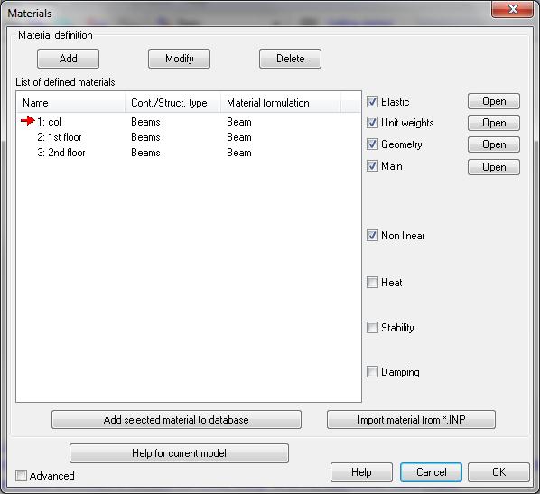
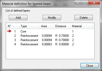
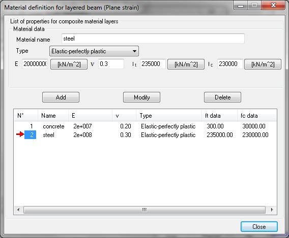
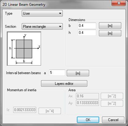
21 Application: Material definition for RC members


22 PUSHOVER TIME HISTORY Application: Seismic demand Accelerogram generated Synthetically (Sabetta) COMPATIBLE
23 Contents Motivation Why pushover? Why take soil into account? Brief recall of pushover theory Application: 2-storey RC frame Structural-only analysis Nonlinear time history analysis (reference solution) Nonlinear pushover analysis Taking soil into account Nonlinear time history analysis with DRM (reference solution) Nonlinear pushover analysis Comparison of solutions Conclusions and perspectives

24 Application: Time history analysis (reference solution)
25 Application: TH displacement time history ux max = 4 cm
26 Application: TH bending moment envelope during TH M max = +106 / -103 knm
27 Contents Motivation Why pushover? Why take soil into account? Brief recall of pushover theory Application: 2-storey RC frame Structural-only analysis Nonlinear time history analysis (reference solution) Nonlinear pushover analysis Taking soil into account Nonlinear time history analysis with DRM (reference solution) Nonlinear pushover analysis Comparison of solutions Conclusions and perspectives
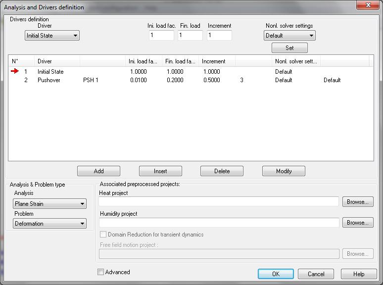
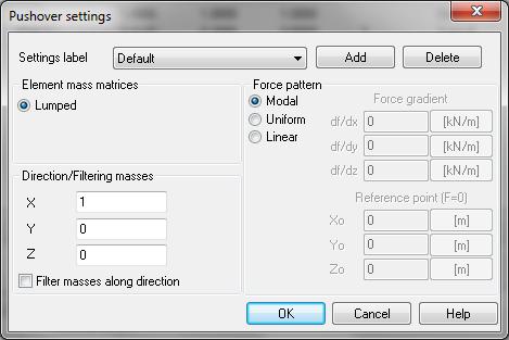
28 Application: Pushover analysis ALSO TRIED
29 Application: Pushover analysis
30 Application: Pushover analysis 5.4 cm
31 Application: Pushover analysis Pushover analysis report Item Unit PSH 1/Default MDOF Free vibr. period...t [s] SDOF Free vibr. period...t* [s] SDOF equivalent mass...m* [kg] Mass participation factor Gamma Bilinear yield force value..fy* [kn] Bilinear displ. at yield...dy* [m] Target displacement...dm* [m] SDOF displacement demand...dt* [m] Energy...Em* [kn*m] Reduction factor...qu - 1 Demand ductility factor...mi Capacity ductility factor...mic MDOF displacement demand...dt [m] d t = 6.5 cm
32 Application: Pushover analysis M max = +94 knm
33 Contents Motivation Why pushover? Why take soil into account? Brief recall of pushover theory Application: 2-storey RC frame Structural-only analysis Nonlinear time history analysis (reference solution) Nonlinear pushover analysis Taking soil into account Nonlinear TH analysis with DRM (reference solution) Nonlinear pushover analysis Comparison of solutions Conclusions and perspectives
 h = 0.5 m b = 1.")
34 Taking soil into account: soil hypotheses Soil (HSS model) E 50 = 80 MPa, E ur = 320 MPa, E 0 = 800 MPa s h,ref = 100 kpa g = 20 kn/m 3, c = 0 kpa, f = 30, y = 10 Interface elements (optional) h = 0.5 m b = 1.4 m
35 Contents Motivation Why pushover? Why take soil into account? Brief recall of pushover theory Application: 2-storey RC frame Structural-only analysis Nonlinear time history analysis (reference solution) Nonlinear pushover analysis Taking soil into account Nonlinear TH analysis with DRM (reference solution) Nonlinear pushover analysis Comparison of solutions Conclusions and perspectives
36 Taking soil into account: Time history analysis with DRM DRM => two models: a reduced model and a background model Seismic input on reduced model = free-field motion of background model

37 Taking soil into account: Time history analysis with DRM Background model (elastic) and free-field motion Horizontal acceleration read at top of soil column 45 m 15 m 10% Rayleigh damping on 2 Hz and 6 Hz => a = 1.88 and b = Seismic input: linear deconvolution of Fig accelerogram Periodic BCs: u x left = u x right
 Boundary layer (elastic) Exterior domain (elastic) Viscous")
38 Taking soil into account: Time history analysis with DRM Reduced model Interior domain (HSS model) Boundary layer (elastic) Exterior domain (elastic) Viscous dampers

39 Taking soil into account: Time history analysis with DRM ux max = -8.0 cm

40 Taking soil into account: Time history analysis with DRM M max = +47 / -43 knm
41 Contents Motivation Why pushover? Why take soil into account? Brief recall of pushover theory Application: 2-storey RC frame Structural-only analysis Nonlinear time history analysis (reference solution) Nonlinear pushover analysis Taking soil into account Nonlinear time history analysis with DRM (reference solution) Nonlinear pushover analysis Comparison of solutions Conclusions and perspectives
42 Taking soil into account: pushover analysis V b max << V b max (struct. Only) Structural only
43 Taking soil into account: pushover analysis
44 Taking soil into account: pushover analysis Pushover analysis report Item Unit PSH 1/Default MDOF Free vibr. period...t [s] SDOF Free vibr. period...t* [s] SDOF equivalent mass...m* [kg] Mass participation factor Gamma Bilinear yield force value..fy* [kn] Bilinear displ. at yield...dy* [m] Target displacement...dm* [m] SDOF displacement demand...dt* [m] Energy...Em* [kn*m] Reduction factor...qu Demand ductility factor...mi Capacity ductility factor...mic MDOF displacement demand...dt [m] d t = 9.7 cm > d t (struct. only) = 6.5 cm

45 Taking soil into account: pushover analysis M max = +31 / -37 knm
46 Contents Motivation Why pushover? Why take soil into account? Brief recall of pushover theory Application: 2-storey RC frame Structural-only analysis Nonlinear time history analysis (reference solution) Nonlinear pushover analysis Taking soil into account Nonlinear time history analysis with DRM (reference solution) Nonlinear pushover analysis Comparison of solutions Conclusions and perspectives
47 STRUCTURAL ONLY TAKING SOIL INTO ACCOUNT Comparison PLAY MOVIES
48 mean stress level under foundation [-] absolute foundation displacement [m] bending moment in column just above foundation [knm] Comparison: «case 2» vs. «case 1» found 1.4 m M struct 1.20E E+02 M struct Mean SL disp 8.00E E+01 Strip (BIG) found 4.00E+01 M struct 2.00E+01 Mean SL disp d(target) = 8 cm d(target) = 9.7 cm 0.00E E E E E E E-01 Top floor displacement [m] found 1.4 m (right) strip (BIG) found struct only Mean Stress Level disp E E E E E E-01 Top floor displacement [m] E E E E E E-01 top floor displacement [m] found 1.4 m (right) strip (BIG) found found 1.4 m (right) strip (BIG) found
49 Comparison Time history (with DRM) Pushover analysis Difference PO vs. TH d top min/max drift min/max M min/max d t drift(d t ) M max (d t ) on d max on M max [cm] [cm] [knm] [cm] [cm] [knm] [%] [%] structural only -2.3/ / / with soil -8.0/ / / with soil, BIG foundation -4.8/ / /
50 Contents Motivation Why pushover? Why take soil into account? Brief recall of pushover theory Application: 2-storey RC frame Structural-only analysis Nonlinear time history analysis (reference solution) Nonlinear pushover analysis Taking soil into account Nonlinear time history analysis with DRM (reference solution) Nonlinear pushover analysis Comparison of solutions Conclusions and perspectives
 leads to: d >> design M(struct) << => gain!")
51 Conclusions and perspectives Taking soil into account (if in case 2!) leads to: d >> design M(struct) << => gain! Needs more benchmarking Thank you Thomas for ideas
STRUCTURAL PUSHOVER ANALYSIS
 STRUCTURAL PUSHOVER ANALYSIS Contents 1 Problem Description 2 2 Data Preparation 3 2.1 Project creation 3 2.2 Pre-processing 4 2.3 Material definition 14 2.4 Analysis and drivers definition 18 3 Calculation
Equivalent SDOF Systems to Simulate MDOF System Behavior
 Equivalent SDOF Systems to Simulate MDOF System Behavior Erol Kalkan PEER-GMSM, Berkeley Aug- How to find equivalent SDOF systems via Pushover analysis: MDOF system seismic behavior can be approximated
APPLICATION OF PUSHOVER ANALYSIS ON EARTHQUAKE RESPONSE PREDICATION OF COMPLEX LARGE-SPAN STEEL STRUCTURES
 APPLICATION OF PUSHOVER ANALYSIS ON EARTHQUAKE RESPONSE PREDICATION OF COMPLEX LARGE-SPAN STEEL STRUCTURES J.R. Qian 1 W.J. Zhang 2 and X.D. Ji 3 1 Professor, 3 Postgraduate Student, Key Laboratory for
Adaptive Pushover Analysis of Irregular RC Moment Resisting Frames
 Kalpa Publications in Civil Engineering Volume 1, 2017, Pages 132 136 ICRISET2017. International Conference on Research and Innovations in Science, Engineering &Technology. Selected papers in Civil Engineering
Application of pushover analysis in estimating seismic demands for large-span spatial structure
 28 September 2 October 2009, Universidad Politecnica de Valencia, Spain Alberto DOMINGO and Carlos LAZARO (eds.) Application of pushover analysis in estimating seismic demands for large-span spatial structure
The Adequacy of Pushover Analysis to Evaluate Vulnerability of Masonry Infilled Steel Frames Subjected to Bi-Directional Earthquake Loading
 The Adequacy of Pushover Analysis to Evaluate Vulnerability of Masonry Infilled Steel Frames Subjected to Bi-Directional Earthquake Loading B.Beheshti Aval & M. Mohammadzadeh K.N.Toosi University of Technology,
Reinforced Soil Retaining Walls-Design and Construction
 Lecture 32 Reinforced Soil Retaining Walls-Design and Construction Prof. G L Sivakumar Babu Department of Civil Engineering Indian Institute of Science Bangalore 560012 Example calculation An 8 m high
Non-Linear Seismic Analysis of Multi-Storey Building
 Non-Linear Seismic Analysis of Multi-Storey Building Uzair Khan 1 1 M.Tech (Structural & Construction Engineering) Department of Civil Engineering, National Institute of Technology, Jalandhar. Hina Gupta
Dynamic response of composite caissonpiles
 Dynamic response of composite caissonpiles foundations Maosong Huang Department of Geotechnical Engineering Tongji University, Shanghai, China Outline of talk 1 Introduction 2 Lateral response 3 Seismic
Pushover Analysis of Water Tank Staging
 Pushover Analysis of Water Tank Dhiraj Virkhare 1, Prof. Laxmikant Vairagade 2, Vikrant Nair 3 1 P.G. Student, Civil Engineering Department, G.H.R.A.E.T Nagpur, Maharashtra, India 2Assistant Professor,
Pushover Analysis Of Steel Frames Welcome To Ethesis
 We have made it easy for you to find a PDF Ebooks without any digging. And by having access to our ebooks online or by storing it on your computer, you have convenient answers with pushover analysis of
m v = 1.04 x 10⁻⁴ m 2 /kn, C v = 1.29 x 10⁻² cm 2 /min
 2.10 Problems Example 2.1: Design of Shallow Foundation in Saturated Clay Design a square footing to support a column load of 667 kn. The base of the footing will be located 1 m below the ground level
Applicability of Nonlinear Static Procedures to RC Moment-Resisting Frames
 Applicability of Nonlinear Static Procedures to RC Moment-Resisting Frames Michalis Fragiadakis 1, Dimitrios Vamvatsikos 2, and Mark Aschheim 3 1 Post-doctoral Scholar, University of Cyprus, Nicosia, Cyprus,
Displacement-based calculation method on soil-pile interaction of PHC pipe-piles
 Seattle, WA Displacement-based calculation method on soil-pile interaction of PHC pipe-piles Dr. Huang Fuyun Fuzhou University 31 st May, 217 Outline Background ing introduction ing results Simple calculation
Pushover Analysis of 4 Storey s Reinforced Concrete Building
 Pushover Analysis of 4 Storey s Reinforced Concrete Building Kavita Golghate Student, Department of Civil Engineering Vijay Baradiya Associate Professor, Department of Civil Engineering Amit Sharma Associate
Seismic Response of Skewed RC Box-Girder Bridges
 Seismic Response of ed RC Box-Girder Bridges Gokhan Pekcan 1 and Ahmed Abdel-Mohti 2 1 Assistant Prof., Department of Civil and Environmental Engineering, University of Nevada Reno, NV 89557. 2 Graduate
Pushover Analysis of G+3 Reinforced Concrete Building with soft storey
 IOSR Journal of Mechanical and Civil Engineering (IOSR-JMCE) e-issn: 2278-1684,p-ISSN: 2320-334X, Volume 11, Issue 4 Ver. I (Jul- Aug. 2014), PP 25-29 Pushover Analysis of G+3 Reinforced Concrete Building
PUSHOVER ANALYSIS OF STEEL STRUCTURE Santosh shet 1, Dr.Akshatha shetty 2 1
 PUSHOVER ANALYSIS OF STEEL STRUCTURE Santosh shet 1, Dr.Akshatha shetty 2 1 P.G Student, NMAMIT Engineering college Nitte Karkala, Karnataka,India 2 Assistant Professor NMAMIT Engineering college Nitte
RELIABILITY ASSESSMENT, STATIC AND DYNAMIC RESPONSE OF TRANSMISSION LINE TOWER: A COMPARATIVE STUDY
 RELIABILITY ASSESSMENT, STATIC AND DYNAMIC RESPONSE OF TRANSMISSION LINE TOWER: A COMPARATIVE STUDY Yusuf Mansur Hashim M. Tech (Structural Engineering) Student, Sharda University, Greater Noida, (India)
A CASE STUDY CONSIDERING A 3-D PUSHOVER ANALYSIS PROCEDURE
 ABSTRACT : A CASE STUDY CONSIDERING A 3-D PUSHOVER ANALYSIS PROCEDURE W. Huang 1 and P. L. Gould 2 1 KPFF Consulting Engineers, Los Angeles, CA, USA 2 Professor, Washington University, Saint Louis, MO,
Soil-Structure Interaction Analysis for Bridge Caisson Foundation
 Missouri University of Science and Technology Scholars' Mine International Conferences on Recent Advances in Geotechnical Earthquake Engineering and Soil Dynamics 2010 - Fifth International Conference
SYSTEM IDENTIFICATION AND RESPONSE ANALYSIS OF RC HIGH-RISE BUILDINGS UNDER SUCCESSIVE EARTHQUAKES
 SYSTEM IDENTIFICATION AND RESPONSE ANALYSIS OF RC HIGH-RISE BUILDINGS UNDER SUCCESSIVE EARTHQUAKES Muhammad Rusli MEE54 Supervisor: Taiki SAITO ABSTRACT System identification was performed to two RC high-rise
Session 1. Pushover Analysis of a Torsionally Eccentric Cellular Abutment. Date 11/03/ PM 4 PM Eastern Time
 Session 1 Pushover Analysis of a Torsionally Eccentric Cellular Abutment Date 11/03/2016 3 PM 4 PM Eastern Time Today s Presenter: Jon Emenheiser, PE Copyright Materials This presentation is protected
Seismic performance of partially submerged R.C. caissons used in port structures
 Proceedings of the 9th International Conference on Structural Dynamics, EURODYN 214 Porto, Portugal, 3 June - 2 July 214 A. Cunha, E. Caetano, P. Ribeiro, G. Müller (eds.) ISSN: 2311-92; ISBN: 978-972-752-165-4
SOIL-STRUCTURE INTERACTION ANALYSIS OF THE MANHATTAN BRIDGE FOUNDATIONS
 10NCEE Tenth U.S. National Conference on Earthquake Engineering Frontiers of Earthquake Engineering July 21-25, 2014 Anchorage, Alaska SOIL-STRUCTURE INTERACTION ANALYSIS OF THE MANHATTAN BRIDGE FOUNDATIONS
Catenary Mooring Chain Eigen Modes and the Effects on Fatigue Life
 Catenary Mooring Chain Eigen Modes and the Effects on Fatigue Life Tor Anders Nygaard and Jacobus de Vaal, IFE Morten Hviid Madsen and Håkon Andersen, Dr.techn Olav Olsen AS Jorge Altuzarra, Vicinay Marine
A comprehensive method for the structural design and verification of the INNWIND 10MW tri-spar floater
 NATIONAL TECHNICAL UNIVERSITY of ATHENS (NTUA) A comprehensive method for the structural design and verification of the INNWIND 10MW tri-spar floater DI Manolas, CG Karvelas, IA Kapogiannis, VA Riziotis,
For a cantilever pile wall shown in Figure 1, assess the performance of the system and answer the following questions.
 Question 1 For a cantilever pile wall shown in Figure 1, assess the performance of the system and answer the following questions. Figure 1 - Cantilever Pile Wall i. Estimate the net resulting horizontal
midas Gen V.741 Enhancements Analysis & Design Part
 V.741 Enhancements Part Concrete / Steel pushover analysis & safety verification as per Eurocode 8-3: 2004 Masonry pushover analysis & global assessment as per OPCM3431 Lateral-Torsional Buckling Analysis
[Barve, 4(7): July, 2015] ISSN: (I2OR), Publication Impact Factor: 3.785
![[Barve, 4(7): July, 2015] ISSN: (I2OR), Publication Impact Factor: 3.785](/thumbs/96/128298826.jpg "[Barve, 4(7): July, 2015] ISSN: (I2OR), Publication Impact Factor: 3.785") IJESRT INTERNATIONAL JOURNAL OF ENGINEERING SCIENCES & RESEARCH TECHNOLOGY PARAMETRIC STUDY TO UNDERSTAND THE SEISMIC BEHAVIOUR OF INTZE TANK SUPPORTED ON SHAFT Prasad S. Barve *, Ruchi P. Barve * Civil
IJESRT INTERNATIONAL JOURNAL OF ENGINEERING SCIENCES & RESEARCH TECHNOLOGY PARAMETRIC STUDY TO UNDERSTAND THE SEISMIC BEHAVIOUR OF INTZE TANK SUPPORTED ON SHAFT Prasad S. Barve *, Ruchi P. Barve * Civil
DEVELOPMENT AND VERIFICATION OF A FULLY ADAPTIVE PUSHOVER PROCEDURE
 Published by Elsevier Science Ltd. All rights reserved 12 th European Conference on Earthquake Engineering Paper Reference 822 DEVELOPMENT AND VERIFICATION OF A FULLY ADAPTIVE PUSHOVER PROCEDURE S. Antoniou
Comparison and Sensitivity Investigations of a CALM and SALM Type Mooring System for Wave Energy Converters
 J. Mar. Sci. Eng. 214, 2, 93-122; doi:1.339/jmse2193 Article OPEN ACCESS Journal of Marine Science and Engineering ISSN 277-1312 www.mdpi.com/journal/jmse Comparison and Sensitivity Investigations of a
Irrigation &Hydraulics Department lb / ft to kg/lit.
 CAIRO UNIVERSITY FLUID MECHANICS Faculty of Engineering nd Year CIVIL ENG. Irrigation &Hydraulics Department 010-011 1. FLUID PROPERTIES 1. Identify the dimensions and units for the following engineering
Vibration of floors and footfall analysis
 Webinar Autodesk Robot Structural Analysis Professional 20/04/2016 Vibration of floors and footfall analysis Artur Kosakowski Rafał Gawęda Webinar summary In this webinar we will focus on the theoretical
Quantification of the Effects of Turbulence in Wind on the Flutter Stability of Suspension Bridges
 Quantification of the Effects of Turbulence in Wind on the Flutter Stability of Suspension Bridges T. Abbas 1 and G. Morgenthal 2 1 PhD candidate, Graduate College 1462, Department of Civil Engineering,
GEA FOR ADVANCED STRUCTURAL DYNAMIC ANALYSIS
 SMART SOLUTIONS FOR VIBRATION MONITORING GEA FOR ADVANCED STRUCTURAL DYNAMIC ANALYSIS ANALYSIS OF CIVIL STRUCTURES - EXPO MERLATA PEDESTRIAN BRIDGE ABSTRACT Civil structures and in particular bridges and
V-H-M Yield Surface describing Soil Structure Interaction of Sub-sea Structures and Wind Turbines on Caisson Foundations in Soft Clays
 NGM 2016 Reykjavik Proceedings of the 17 th Nordic Geotechnical Meeting Challenges in Nordic Geotechnic 25 th 28 th of May V-H-M Yield Surface describing Soil Structure Interaction of Sub-sea Structures
Lateral Load Analysis Considering Soil-Structure Interaction. ANDREW DAUMUELLER, PE, Ph.D.
 Lateral Load Analysis Considering Soil-Structure Interaction ANDREW DAUMUELLER, PE, Ph.D. Overview Introduction Methods commonly used to account for soil-structure interaction for static loads Depth to
Effect of Wind Pressure on R.C Tall Buildings using Gust Factor Method
 Effect of Wind Pressure on R.C Tall Buildings using Gust Factor Method Ranjitha K. P 1 PG Student, Department of Civil Engineering Ghousia College of Engineering Ramanagar-562159 Dr. N.S. Kumar 3 Professor
Hatch cover securing and tightness
 (1986) (Rev 1 1996) (Corr.1 June 2000) (Rev.2 July 2005) (Corr.1 Oct 2005) Hatch cover securing and tightness 1. Application 1.1 The following recommendations apply to steel hatch covers that are fitted
G.C.E (A/L) Examination March In collaboration with
 Examination March In collaboration with") ; G.C.E (A/L) Examination March - 2018 Conducted by Field Work Centre, Thondaimanaru In collaboration with FWC Provincial Department of Education Northern Province Grade:- 12 (2019) Physics Part - II Structured
; G.C.E (A/L) Examination March - 2018 Conducted by Field Work Centre, Thondaimanaru In collaboration with FWC Provincial Department of Education Northern Province Grade:- 12 (2019) Physics Part - II Structured
Bending Vibration Analysis of Pipes and Shafts Arranged in Fluid Filled Tubular Spaces Using FEM
 Bending Vibration Analysis of Pipes and Shafts Arranged in Fluid Filled Tubular Spaces Using FEM By Desta Milkessa Under the guidance of : Prof. Dr.Eng. Patrick Kaeding Dipl.-Ing. Michael Holtmann Developed
Offshore Wind Turbine monopile in 50 year storm conditions
 TMR7 Experimental methods in marine hydrodynamics - lab exercise 3 2017 Offshore Wind Turbine monopile in 50 year storm conditions Trygve Kristiansen and Erin Bachynski, Trondheim, 20.09.2017 Background
SEISMIC RESPONSE ANALYSIS OF THE LARGE BRIDGE PIER SUPPORTED BY GROUP PILE FOUNDATION CONSIDERING THE EFFECT OF WAVE AND CURRENT ACTION
 October 2-7, 28, Beijing, China SEISMIC RESPONSE ANALYSIS OF THE LARGE BRIDGE PIER SUPPORTED BY GROUP PILE FOUNDATION CONSIDERING THE EFFECT OF WAVE AND CURRENT ACTION BAI De-gui,2, CHEN Guo-xing and WANG
Quantifying Mainshock Aftershock Collapse Probabilities for Woodframe Buildings. John W. van de Lindt and Negar Nazari The University of Alabama
 Quantifying Mainshock Aftershock Collapse Probabilities for Woodframe Buildings John W. van de Lindt and Negar Nazari The University of Alabama Yue Li Michigan Technological University Aftershocks Great
COUPLED DYNAMIC ANALYSIS OF MOORING LINES FOR DEEP WATER FLOATING SYSTEMS
 Proceedings of International Conference in Ocean Engineering, ICOE Proceedings 2009 of ICOE 2009 Coupled Dynamic Analysis IIT Madras, of Chennai, Mooring India. Lines for Deep Water Floating Systems 1-5
This document downloaded from vulcanhammer.net vulcanhammer.info Chet Aero Marine
 This document downloaded from vulcanhammer.net vulcanhammer.info Chet Aero Marine Don t forget to visit our companion site http://www.vulcanhammer.org Use subject to the terms and conditions of the respective
Nonlinear Static Analysis for Frame2shear2wall Structures
 30 6 2008 12 Earthquake Resistant Engineering and Retrofitting Vol130,No16 Dec. 2008 [] 100228412 (2008) 0620041208,, (,100084) [ ],,, Chopra, MPA MPA,18,,MPA,,MPA [ ] ;;;; [] TU375 ; TU313 [] A Nonlinear
Tresca s or Mises Yield Condition in Pressure Vessel Design
 Tresca s or Mises Yield Condition in Pressure Vessel Design Franz Rauscher Institute for Pressure Vessels and Plant Technology Vienna University of Technology Austria Why using Tresca s yield condition
Wind Action Effects on Mixed Reinforced Concrete Structures in Non Seismic Zones
 EUROPEAN ACADEMIC RESEARCH Vol. III, Issue 7/ October 2015 ISSN 2286-4822 www.euacademic.org Impact Factor: 3.4546 (UIF) DRJI Value: 5.9 (B+) Wind Action Effects on Mixed Reinforced Concrete Structures
Applying Hooke s Law to Multiple Bungee Cords. Introduction
 Applying Hooke s Law to Multiple Bungee Cords Introduction Hooke s Law declares that the force exerted on a spring is proportional to the amount of stretch or compression on the spring, is always directed
Formation level = m. Foundation level = m. Height of the wall above the Ground Level = 7.42 m
 DESIGN OF RETAINING WALL INTRODUCTION: This wall is designed for active earth pressure and live load surcharge pressure The loads for the purpose of design are calculated per meter length of wall. BASIC
Study on the calculation method for hydrodynamic pressure of bridge piers in deep water under earthquakes
 Study on the calculation method for hydrodynamic pressure of bridge piers in deep water under earthquakes Prof. Bo Song University of Science and Technology Beijing main contents 1 The Background of Research
A DISPLACEMENT-BASED ADAPTIVE PUSHOVER FOR SEISMIC ASSESSMENT OF STEEL AND REINFORCED CONCRETE BUILDINGS ABSTRACT
 8 th US National Conference in Earthquake Engineering, San Francisco, US, 17 th 1 st April 6 Paper No. 171 A DISPLACEMENT-BASED ADAPTIVE PUSHOVER FOR SEISMIC ASSESSMENT OF STEEL AND REINFORCED CONCRETE
SHAKING TABLE TESTS AND EFFECTIVE STRESS ANALYSES ON THE DYNAMIC BEHAVIOR OF WEDGED CAISSONS
 SHAKING TABLE TESTS AND EFFECTIVE STRESS ANALYSES ON THE DYNAMIC BEHAVIOR OF WEDGED CAISSONS Takahiro SUGANO 1, Katsumi KISHITANI 2, Masaaki MITO 3, Kou NISHINAKAGAWA 4, Shin'ichi IDO 5, Masanori SHIMA
2 Available: 1390/08/02 Date of returning: 1390/08/17 1. A suction cup is used to support a plate of weight as shown in below Figure. For the conditio
 1. A suction cup is used to support a plate of weight as shown in below Figure. For the conditions shown, determine. 2. A tanker truck carries water, and the cross section of the truck s tank is shown
computed using Equation 3-18 by setting the 2nd term equal to 0 and K A equal to K o and using the pressure distribution as shown in Figure 3-23.
 computed using Equation 3-18 by setting the 2nd term equal to 0 and K A equal to K o and using the pressure distribution as shown in Figure 3-23. (2) For the resisting side, passive pressure theory indicates
Analysis of dilatometer test in calibration chamber
 Analysis of dilatometer test in calibration chamber Lech Bałachowski Gdańsk University of Technology, Poland Keywords: calibration chamber, DMT, quartz sand, FEM ABSTRACT: Because DMT in calibration test
TLP Minimum tendon tension design and tendon down-stroke investigation
 Published by International Association of Ocean Engineers Journal of Offshore Engineering and Technology Available online at www.iaoejoet.org TLP Minimum tendon tension design and tendon down-stroke investigation
WAVE MECHANICS FOR OCEAN ENGINEERING
 Elsevier Oceanography Series, 64 WAVE MECHANICS FOR OCEAN ENGINEERING P. Boccotti Faculty of Engineering University of Reggio-Calabria Feo di Vito 1-89060 Reggio-Calabria Italy 2000 ELSEVIER Amsterdam
6.0 ENGINEERING. Build Anything Better. REPRINTED 2017
 6.0 ENGINEERING TABLE OF CONTENTS 6.1 U.S. ENGINEERING ANALYSIS REPORT... P. 6-3 BELOW-GRADE WALL REINFORCEMENT TABLES... P. 6-5 ABOVE-GRADE WALL REINFORCEMENT TABLES.. P. 6-21 LINTEL REINFORCEMENT TABLES...P.
Wind effects on tall building frames-influence of dynamic parameters
 Indian Journal of Science and Technology Vol. 3 No. 5 (May 21) ISSN: 974-6846 583 Wind effects on tall building frames-influence of dynamic parameters B. Dean Kumar 1 and B.L.P. Swami 2 1 Department of
Dynamic Response of Jacket Structures to Breaking and Nonbreaking Waves: Yesterday, Today, Tomorrow
 Leichtweiß-Institute for Hydraulic Engineering and Water Resources Department of Hydromechanics and Coastal Engineering Dynamic Response of Jacket Structures to Breaking and Nonbreaking Waves: Yesterday,
Finite Element Analysis of Offshore Jacket Affected by Marine Forces
 Bulletin of Environment, Pharmacology and Life Sciences Bull. Env.Pharmacol. Life Sci., Vol 4 [Spl issue 1] 2015: 152-159 2014 Academy for Environment and Life Sciences, India Online ISSN 2277-1808 Journal
Item 404 Driving Piling
 Item Driving Piling 1. DESCRIPTION Drive piling. 2. EQUIPMENT 2.1. Driving Equipment. Use power hammers for driving piling with specified bearing resistance. Use power hammers that comply with Table 1.
ITTC Recommended Procedures and Guidelines
 Page 1 of 6 Table of Contents 1. PURPOSE...2 2. PARAMETERS...2 2.1 General Considerations...2 3 DESCRIPTION OF PROCEDURE...2 3.1 Model Design and Construction...2 3.2 Measurements...3 3.5 Execution of
Edit this text for your title
 Edit this text for your title MEK 4450 Marine Operations Edit this text for your sub-title Presenter name, location, date etc. Kværner ASA / DNV, Fall 2013 Lesson 2/3 Lift phases Load out Transportation
MODEL SHAKE TABLE TEST ON THE SEISMIC PERFORMANCE OF GRAVITY TYPE QUAY WALL WITH DIFFERENT FOUNDATION GROUND PROPERTIES
 th World Conference on Earthquake Engineering Vancouver, B.C., Canada August -6, Paper No. 5 MODEL SHAKE TABLE TEST ON THE SEISMIC PERFORMANCE OF GRAVITY TYPE QUAY WALL WITH DIFFERENT FOUNDATION GROUND
Friction properties of the face of a hand-held tennis racket
 Available online at www.sciencedirect.com Procedia Engineering 34 (2012 ) 544 549 9 th Conference of the International Sports Engineering Association (ISEA) Friction properties of the face of a hand-held
Dynamic Analysis of the Rotterdam Central Station Footbridge Breman, C.; Stuit, H.G.; Snijder, H.H.
 Dynamic Analysis of the Rotterdam Central Station Footbridge Breman, C.; Stuit, H.G.; Snijder, H.H. Published in: Proceedings of the 4th International Footbridge Conference, 6-8 July 11, Wroclaw, Poland
Redesign of a Tennis Racket for Reduced Vibrations and Improved Control and Power. MENG 370 Design Project Report Fall 2012 Semester
 MENG 370: Element Machine Design, Fall 2012, Professor: Jong B. Lee, Ph.D. 1 Redesign of a Tennis Racket for Reduced Vibrations and Improved Control and Power MENG 370 Design Project Report Fall 2012 Semester
+ t1 t2 moment-time curves
 Part 6 - Angular Kinematics / Angular Impulse 1. While jumping over a hurdle, an athlete s hip angle was measured to be 2.41 radians. Within 0.15 seconds, the hurdler s hip angle changed to be 3.29 radians.
Special Considerations for Structural design and Fabrication for. tankers or similar vessels with Large Size (150m or more in length) in.
 in.") Special Considerations for Structural design and Fabrication for tankers or similar vessels with Large Size (150m or more in length) in polar waters He. Guangwei Guangwei_ho@chinagsi.com Mai. Rongzhi MRZ@chinagsi.com
Special Considerations for Structural design and Fabrication for tankers or similar vessels with Large Size (150m or more in length) in polar waters He. Guangwei Guangwei_ho@chinagsi.com Mai. Rongzhi MRZ@chinagsi.com
A MODEL FOR ANALYSIS OF THE IMPACT BETWEEN A TENNIS RACKET AND A BALL
 A MODEL FOR ANALYSIS OF THE IMPACT BETWEEN A TENNIS RACKET AND A BALL Hiroshi Maeda, Masaaki Okauchi and Yoshio Shimada Faculty of Engineering, Oita University, Oita City, Oita, Japan The purpose of this
Mechanical Stabilisation for Permanent Roads
 Mechanical Stabilisation for Permanent Roads Tim Oliver VP Global Applications Technology Tensar International toliver@tensar.co.uk Effect of geogrid on particle movement SmartRock Effect of geogrid on
Analysis and Research of Mooring System. Jiahui Fan*
 nd International Conference on Computer Engineering, Information Science & Application Technology (ICCIA 07) Analysis and Research of Mooring System Jiahui Fan* School of environment, North China Electric
Feasibility study of a semi floating spar buoy wind turbine anchored with a spherical joint to the sea floor
 Feasibility study of a semi floating spar buoy wind turbine anchored with a spherical joint to the sea floor María Sanz Martínez DTU Wind Energy DK-4000 Roskilde, Denmark msma@dtu.dk Anand Natarajan DTU
Optimal Football Pressure as a Function of a Footballer s Physical Abilities
 Proceedings Optimal Football Pressure as a Function of a Footballer s Physical Abilities Andrew Christenson 1, *, Pei Cao 2 and Jiong Tang 2 1 Edwin O. Smith High School, 1235 Storrs Road, Storrs, CT 06268,
Footbridge 2005 Second International Conference
 ASSESSMENT AND CONTROL OF HUMAN INDUCED VIBRATIONS IN THE NEW COIMBRA FOOTBRIDGE Elsa CAETANO Assistant Professor University of Porto Porto, Portugal Álvaro CUNHA Associate Professor University of Porto
CIVL473 Fundamentals of Steel Design
 Loading for most of the structures are obtained from the relevant British Standards, the manufacturers data and similar sources. CIVL473 Fundamentals of Steel Design CHAPTER 2 Loading and Load Combinations
Typical factors of safety for bearing capacity calculation in different situations
 Typical factors of safety for bearing capacity calculation in different situations Density of soil: In geotechnical engineering, one deals with several densities such as dry density, bulk density, saturated
LYSAGHT W-DEK. Design and Construction Manual. Structural steel decking system
 LYSAGHT W-DEK Structural steel decking system Design and Construction Manual ptimised to bring greater efficiency, speed of construction and economy. Exceptional spanning characteristics (up to 4.1m) reduces
DYNAMIC CRUSH TEST ON HYDROGEN PRESSURIZED CYLINDER
 DYNAMIC CRUSH TEST ON HYDROGEN PRESSURIZED CYLINDER Hiroyuki Mitsuishi 1, Koichi Oshino 2, Shogo Watanabe 2 1 Japan Automobile Research Institute, Takaheta1328-23, Shirosato, Ibaraki, 311-4316, Japan 2
EFFECTS OF SIDEWALL OPENINGS ON THE WIND LOADS ON PIPE-FRAMED GREENHOUSES
 The Seventh Asia-Pacific Conference on Wind Engineering, November 8-12, 29, Taipei, Taiwan EFFECTS OF SIDEWALL OPENINGS ON THE WIND LOADS ON PIPE-FRAMED GREENHOUSES Yasushi Uematsu 1, Koichi Nakahara 2,
Equation 1: F spring = kx. Where F is the force of the spring, k is the spring constant and x is the displacement of the spring. Equation 2: F = mg
 1 Introduction Relationship between Spring Constant and Length of Bungee Cord In this experiment, we aimed to model the behavior of the bungee cord that will be used in the Bungee Challenge. Specifically,
Effect of Depth of Periphery Beams on Behavior of Grid Beams on Grid Floor
 International Journal of Current Engineering and Technology E-ISSN 2277 4106, P-ISSN 2347 5161 2015 INPRESSCO, All Rights Reserved Available at http://inpressco.com/category/ijcet Research Article Effect
Realistic Seismic Behavior of the Main Tower of the New SAS Bay Bridge and Its Base Anchors
 Realistic Seismic Behavior of the Main Tower of the New SAS Bay Bridge and Its Base Anchors Abolhassan Astaneh-Asl, Ph.D., P.E., Professor Xin Qian, Doctoral Graduate Student Maryam Tabbakhha, Ph.D., Lecturer
Example 4 - Airbag. Summary
 Example 4 - Airbag Summary This example deals with the deployment of a chambered airbag modeled by monitored volumes using communications. The airbag is initially folded along four fold lines. The fabric
Yasuyuki Hirose 1. Abstract
 Study on Tsunami force for PC box girder Yasuyuki Hirose 1 Abstract In this study, a waterway experiment was performed in order to understand the influence of tsunami forms on tsunami forces acting on
EMA and Other Dynamic Testing of a 2-Span Prestressed Concrete Floor. Tuan Nguyen, Nicholas Haritos, Emad Gad and John Wilson
 EMA and Other Dynamic Testing of a 2-Span Prestressed Concrete Floor Tuan Nguyen, Nicholas Haritos, Emad Gad and John Wilson INTRODUCTION This paper discusses experimental modal analysis (EMA) using swept
Downloaded from Downloaded from /1
 VI SEMESTER FINAL EXAMINATION-2003 Q. [1] [a] Draw a right angle four-arm intersection of two roads and show various conflicts points if [a] both roads are with way movements, and [b] one road is with
JAR-23 Normal, Utility, Aerobatic, and Commuter Category Aeroplanes \ Issued 11 March 1994 \ Section 1- Requirements \ Subpart C - Structure \ General
 JAR 23.301 Loads \ JAR 23.301 Loads (a) Strength requirements are specified in terms of limit loads (the maximum loads to be expected in service) and ultimate loads (limit loads multiplied by prescribed
Research on Shear Test methods of bonded steel bolts
 Research on Shear Test methods of bonded steel bolts *Quan Xueyou 1), Li Xiongsong 2) and Luo Chujie 2) 1), 2) School of Civil Engineering, Chongqing University 1), 2) Key Laboratory of New Technology
Appendix Table of Contents:
 Appendix Table of Contents: Page: I. Appendix A 30 1. Existing Conditions Calculations o Design Loads o Seismic Calculations o Wind Calculations o Spot Checks II. Appendix B... 35 2. Proposed Calculations
A new theory for downslope windstorms and trapped lee wave François Lott Lab. Météorologie Dynamique, Ecole Normale Supérieure, Paris
 A new theory for downslope windstorms and trapped lee wave François Lott Lab. Météorologie Dynamique, Ecole Normale Supérieure, Paris 1)Motivation: trapped lee waves 2)Model description 3)Downslope windstorms
Dynamic Characteristics of the End-effector of a Drilling Robot for Aviation
 International Journal of Materials Science and Applications 2018; 7(5): 192-198 http://www.sciencepublishinggroup.com/j/ijmsa doi: 10.11648/j.ijmsa.20180705.14 ISSN: 2327-2635 (Print); ISSN: 2327-2643
CVEN Computer Applications in Engineering and Construction. Programming Assignment #4 Analysis of Wave Data Using Root-Finding Methods
 CVEN 30-501 Computer Applications in Engineering and Construction Programming Assignment #4 Analysis of Wave Data Using Root-Finding Methods Date distributed: 9/30/016 Date due: 10/14/016 at 3:00 PM (electronic
Tutorial. BOSfluids. Relief valve
 Tutorial Relief valve The Relief valve tutorial describes the theory and modeling process of a pressure relief valve or safety valve. It covers the algorithm BOSfluids uses to model the valve and a worked
SHEAR PERFORMANCE OF RC FOOTING BEAMS BY CAP-TIE SYSTEM USING WELDED STIRRUPS
 The 7th International Conference of Asian Concrete Federation SUSTAINABLE CONCRETE FOR NOW AND THE FUTURE 3 Oct 2 Nov, 216, Hanoi, Vietnam www.acf216.vn SHEAR PERFORMANCE OF RC FOOTING BEAMS BY CAP-TIE
UNIT-I SOIL EXPLORATION
 SIDDHARTH GROUP OF INSTITUTIONS :: PUTTUR Siddharth Nagar, Narayanavanam Road 517583 QUESTION BANK (DESCRIPTIVE) Subject with Code : Geotechnical Engineering - II (16CE127) Year & Sem: III-B.Tech & II-Sem