OMC-140 Multifunctional NMEA display. Operators Manual. Version Author: Observator Instruments
|
|
|
- Brendan Holland
- 6 years ago
- Views:
Transcription


1 OMC-140 Multifunctional NMEA display Operators Manual Version Author: Observator Instruments
2 Revisions: 1.01 July 2014 First issue 1.02 Oct 2014 Preliminary edition 1.03 April 2015 Test Manual 1.04 Dec 2015 First Release OMC-140 Operators Manual Page 2
3 Index 1 Introduction Safety Display functions Home screen Wind Home screen GPS Default Home screen functions: Touch Buttons: Default Indicators: Home Screen Heading Default Home screen functions: Touch Buttons: Default Indicators: Available indicators: General Settings Screen Average (wind only) Wind Speed (wind only) Dimming control Sensor Selection Speed reference (wind only) User Avg.(Average) Interval (wind only) Advanced functions Wind Display Orientation: Relative vs Theoretical vs True Wind display orientation Drift Heading vs Course Speed through water (VHW from speed log) vs Speed over ground (gps) Wind Orientation Reference Requirements Terms, Abbreviations & Symbols list Terms & Abbreviations used in this manual Symbols Digital interface NMEA software Inputs: Outputs: NMEA Message description Connections Main connections DC power module connections Remote keypad and relay module Options Remote control unit Specifications Inputs/Outputs TFT touch screen Electrical Environmental specifications Dimming possibilities Dimensions (see drawings on following page) Alarms In accordance with Dimensional drawings Menu structure Touch screen Appendix: Declaration of Conformity OMC-140 Operators Manual Page 3
4 Page intentionally left blank OMC-140 Operators Manual Page 4
5 1 Introduction The OMC- 140 is a multi functional NMEA display primarily designed for wind information. It is capable of calculation Theoretical and True wind if required data is available. This manual is intended for the Operator of the display. An Operators Guide with the basic essential information is also available. For installation instructions we kindly refer to the Installation manual. The Installation manual also contains information for the system administrator. OMC-140 Operators Manual Page 5


6 2 Safety Do not open display. Potential lethal voltages inside. No user exchangeable parts inside. Only use indoors. For outdoor use an IP66 or better housing is required. For correct functioning of this display the display and connected sensors must be installed according installation instructions as described in the OMC-140 Installation manual. Remember: instruments are tools. They do NOT replace your own observations! After end of life dispose this product according local regulations or return to manufacturer. OMC-140 Operators Manual Page 6


7 3 Display functions The examples used in this chapter display the default layout. It is possible to customize the layout by adding, removing parameters or change their position. 3.1 Home screen Wind Marine Display: Land Display: OMC-140 Operators Manual Page 7


8 Home screen buttons : Select between Day or Night mode. In Night mode a darker color palette reduces the emitted light intensity. Brightness slider bar. In Automatic or NMEA control mode use this to set an offset. Opens the settings menu Only visible when an alert is active. Touch this button to acknowledge the alarm. Changes orientation of the display: Relative, Theoretical or True Availability of the orientations depends on received data. (Marine display only). Changes average interval: 10 min, 2 min, Instant or User*. < indicates the selected interval has not yet been met. *User is a custom selectable interval which can be set via the settings menu. Resets the maximum Gust when the averaging is set to Instant Home screen indicators: Selected Orientation. Relative, Theoretical or True (Marine display only) Wind Direction indicator. Shows the average wind direction over the selected interval time. Wind direction variation over the selected average interval time. Also in the wind circle visualized in light blue: Shows max Gust over the selected interval time. If Instant is selected it shows the Max Gust since last reset. Touch to reset Selected wind sensor and selection mode. OMC-140 Operators Manual Page 8


9 Average interval time. 10 min, 2 min, Instant or User Wind speed average over the selected interval time. Wind speed Unit. Bft, Mph, m/s, Kts or km/h Heart beat. The dot should be running from left to right to indicate the display is working and not frozen. Wind direction variation over the selected average interval time. Average wind direction over the selected average interval. OMC-140 Operators Manual Page 9


10 3.2 Home screen GPS Default Home screen functions: OMC-140 Operators Manual Page 10


11 3.2.2 Touch Buttons: Note: The display is single touch, the display will not respond if multiple touch is detected. Don t place your hand on the edge while trying to touch a button, this could be detected as a touch. Select between Day or Night mode. In Night mode a darker color palette reduces the emitted light intensity. Brightness slider bar. In Automatic or NMEA control mode use this to set an offset. Opens the settings menu Only visible when an alarm is active. Touch this button to acknowledge the alarm. Geographical Position (GGA)* Touching will toggle between UTM data** if available and the Geographical data **Requires UTM data input (GMP)*. Speed and Course over ground (VTG)* Touching will switch to Arrow Speed display (Velocity & Drift) if available***. ***Requires Heading data input (HDT or THS)*. * Reference to the required NMEA input message OMC-140 Operators Manual Page 11

12 3.2.3 Default Indicators: These are the factory default. GPS Identifier. Can be set in the Settings menu Heart beat. The dot should be running from left to right to indicate the display is working and not frozen. UTC time (GGA)* Number of Satellites (GGA)* Accuracy HDOP (GGA)* Differential Signal received YES / NO (GGA)* * Reference to the required NMEA input message OMC-140 Operators Manual Page 12


13 3.3 Home Screen Heading Default Home screen functions: OMC-140 Operators Manual Page 13

14 3.3.2 Touch Buttons: Note: The display is single touch, the display will not respond if multiple touch is detected. Don t place your hand on the edge while trying to touch a button, since this could be detected as a touch. Select between Day or Night mode. In Night mode a darker color palette reduces the emitted light intensity. Brightness slider bar. In Automatic or NMEA control mode use this to set an offset. Opens the settings menu Only visible when an alarm is active. Touch this button to acknowledge the alarm. Heading from Gyro (THS or HDT)* Touch will toggle between Heading and Course Course Over Ground (VTG)* * Reference to the required NMEA input message OMC-140 Operators Manual Page 14

15 3.3.3 Default Indicators: These are the factory default indicators: GPS Identifier. Can be set in the Settings menu Heart beat. The dot should be running from left to right to indicate the display is working and not frozen. Speed Over Ground (VTG)* Course Over Ground (COG)* * Reference to the required NMEA input message OMC-140 Operators Manual Page 15

16 3.4 Available indicators: These can be configured for all display types in the Advanced menu. Please Note: The corresponding NMEA message must have been received by the display at least once before an indicator can be selected! Maximum Gust over the selected interval time. If Instant is selected it shows the Maximum Gust since last reset. (MWV or MWD)* Touch to reset Wind Direction (MWV or MWD)* Wind Speed (MWV or MWD)* Selected Wind Sensor indicator (MWV or MWD)* Wind variation (MWV or MWD)* Barometric Pressure QFE (at Runway / Helideck Level).(XDR)* Barometric Pressure QNH (at Sea Level) (XDR)* Air Temperature (XDR)* OMC-140 Operators Manual Page 16
17 Dew Point (XDR)* Speed Over Ground (VTG)* Course Over Ground (VTG)* Heading from Gyro (HDT or THS)* UTC time (GGA)* Differential Signal received YES / NO (GGA)* Number of Satellites (GGA)* Accuracy HDOP (GGA)* Age of last received Differential signal (GGA)* Visibility (Dedicated message non NMEA) OMC-140 Operators Manual Page 17
* * Reference to the required NMEA input message OMC-140 Operators Manual Page")
18 Present Weather (Dedicated message non NMEA) Deviation of the Latitude (GST)* Deviation of the Longitude (GST)* * Reference to the required NMEA input message OMC-140 Operators Manual Page 18

19 3.5 General Settings Screen The General Settings Screen is accessible for all users, but some functions can be locked by the administrator, while others might not be available for other reasons. NOTE: General settings display the stored DEFAULT settings, which will be used whenever the display is started. Settings done via the Home screen are considered temporarily changes and not automatically stored in the default settings. Grayed out blocks are not accessible. For example: the User Average Period is only accessible when User is selected at Average Period. The screen is divided in blocks. Touching it will zoom in and allow you to make changes. Use Save & Exit to store your changes and return to the Main screen. Otherwise use Cancel to discard all changes and return to the Main screen. Display will also return to normal operation if no touch is detected for 1 minute. OMC-140 Operators Manual Page 19
20 3.5.1 Average (wind only) Set the interval over which all data (except Gust) will be averaged. Gust will be given over the selected interval (2 & 10 minutes), since last reset (Instant) or at User setting (User). Normally wind information is reported in 10 minute average data. During specific changing conditions you will need to change to 2 minutes average. The OMC-140 can detect those conditions and change automatic between 10 & 2 minute average if Marked Discontinuity is set in Advanced Settings (default is off) Wind Speed (wind only) Selection of wind speed unit Dimming control Select how you would like to control the brightness of the screen. Manual: Brightness is set by the slider bar only Automatic: Brightness is controlled by the build in light sensor. The slider bar can be used to set an offset. NMEA DDC: Brightness is controlled by the NMEA DDC protocol. This can be another display or any other device using the NMEA DDC protocol. The slider bar can be used to set an offset Sensor Selection Only selectable when 2 sensors are connected, otherwise it will be grayed out. Auto: Sensor 1: Sensor 2: Sensor with highest wind speed will be selected Data of sensor on port 1 will be displayed Data of sensor on port 2 will be displayed Speed reference (wind only) Options are only selectable if the required data is available (see chapter 6) Relative: Theoretical: True: Wind direction & speed data related to the bow of the vessel Wind direction & speed data related to the bow of the vessel as if the vessel would have no speed (True wind related to the bow). Wind direction & speed data related to true North User Avg.(Average) Interval (wind only) Set the values for the User settings at Average. OMC-140 Operators Manual Page 20
. - Valid values are 0 600 (seconds).")
21 - For Wind Speed, Direction & Variation this is the Average interval in seconds. - For Gust this is the reset time (Gust is always a 3s average). - Valid values are (seconds). OMC-140 Operators Manual Page 21
22 4 Advanced functions This menu is meant for the system administrator and therefore password protected. Besides installation parameters it allows to lock and unlock settings in the General menu, which can be accessed by the Operator. 5 Wind Display Orientation: Relative vs Theoretical vs True 5.1 Wind display orientation Depending on available data the OMC-140 display is able to display the wind data up to 3 orientations in the marine mode. This mode is fixed during installation, in land mode only the True to North mode is available: a wind rose is displayed and the area between the logo and dim control bar will be empty. Relative orientation: - vessel symbol is displayed - Wind is displayed as measured on board, Wind is displayed relative to the bow off the vessel. True orientation: - Wind Rose is displayed - Wind is displayed as if the vessel would not move heading North. Wind is displayed True to North. Theoretical orientation: - Vessel symbol is displayed - Wind is displayed as if the vessel would not move The wind is displayed True to the bow of the vessel. True and Theoretical wind speed will always be identical, direction difference will be the heading of the vessel (or course if no heading data is available). When the vessel is heading North, Theoretical & True values will be identical. 5.2 Drift Heading vs Course To compensate for drift the display requires heading data (from gyro) besides course over ground (cog) and speed over ground (sog) data (from gps). Without heading data, the display will display True & Theoretical wind once the ships speed is above 1kt. The display will assume the heading is identical to the course for True and Theoretical calculations. Keep in mind this can lead to deviations in situations where you experience significant drift or if the vessel is reversing! Speed through water (VHW from speed log) vs Speed over ground (gps) Speed through water can be used instead of speed over ground. The display will not compensate for drift, but will give the theoretical & true wind data as if the vessel would be still in the water (not necessarily according to ground). OMC-140 Operators Manual Page 22
23 6 Wind Orientation Reference Requirements Required NMEA data for specific Reference: Relative: Theoretical: True: MWV Relative MWV Theoretical MWV relative + Speed (VTG/GGA* or VHW) MWD MWV Relative + Speed (VTG/GGA* or VHW) + Heading (THS or HDT)** MWV Relative + Speed (VHW) AND Heading (THS or HDT) * VTG will be ignored if the SOG < 1kt to avoid incorrect COG data. ** Optional: Heading data is required to compensate for drift. Without heading data, drift will result in a deviation. 7 Terms, Abbreviations & Symbols list 7.1 Terms & Abbreviations used in this manual. Advanced Average COG Course Dimming Control Heading Options QFE QNH Relative Sensor 1 Sensor 2 SOG True Theoretical Wind Variation Advanced menu protected by password Interval over which the average wind speed & direction is calculated Course Over Ground Actual direction the vessel is moving (over ground). Selected means of regulation of the backlight Direction the bow of the vessel is pointing. Option slot information Barometric Pressure at Runway Level Barometric Pressure at Sea level Wind direction & speed as measured. Sensor connected to port 1 of the display Sensor connected to port 2 of the display Speed Over Ground True wind direction & speed related to North Wind direction & speed as if the vessel would have no speed; True wind speed & direction related to the bow of the vessel. The variation in wind direction over the selected Average interval. OMC-140 Operators Manual Page 23
24 7.2 Symbols Select between Day or Night mode. In Night mode a darker color palette reduces the emitted light intensity. Brightness slider bar. In Automatic or NMEA control mode use this to set an offset. Settings menu OMC-140 Operators Manual Page 24
25 8 Digital interface 8.1 NMEA software Inputs: The Display accepts the following NMEA input messages with a maximum rate of 4 per second: $xxddc $xxgga $xxgmp $xxgst $xxhdt $xxmwd $xxmwv $xxths $xxver $xxvhw $xxvtg $xxxdr Dimming control of backlight GPS Lon Lat position GNSS Map Projection Fix Data GNSS Pseudo range Error Statistics Heading from Gyro (replaced by $xxths, display accepts both) True Wind Relative or Theoretical Wind Heading from Gyro Version info Speed through water (direction is not used) Speed and direction over ground Air Temperature, Sea Temperature, Humidity, Dew point, Barometric Pressure (measured), Barometric Pressure QNH (Sea level), Barometric Pressure QFE (Runway level) Outputs: All recognized input messages can be copied to the output Calculated messages $xxmwv $xxmwd Relative or Theoretical Wind True Wind Other functions $xxddc $xxver Dimming control of backlight Version info OMC-140 Operators Manual Page 25
26 8.2 NMEA Message description $--DDC,a,xx,a,a*hh<CR><LF> Sentence Status Flag 2. Color palette 3. Brightness percentage 00 to Display dimming preset 1 $--GGA,hhmmss.ss,llll.ll,a,yyyyy.yy,a,x,xx,x.x,x.x,M,x.x,M,x.x,xxxx*hh<CR><LF> UTC of position 2. Latitude - N/S 3. Longitude - E/W 4. GPS Quality indicator1 5. Number of satellites in use, 00-12, may be different from the number in view 6. Horizontal dilution of precision 7. Altitude re: mean-sea-level (geoid), meters 8. Geoidal separation, meters 9. Age of Differential GPS data 10. Differential reference station ID, $--GMP,hhmmss.ss,c--c,c--c,x.x,x.x,c--c,xx,x.x,x.x,x.x,x.x,x.x,a*hh<CR><LF> UTC of position 2. Map projection identification 3. Map zone 4. X (Northern) component of grid (or local) coordinates 5. Y (Eastern) component of grid (or local) coordinates 6. Mode indicator 7. Total number of satellites in use, HDOP 9. Antenna altitude, meters, re: mean-sea-level (geoid) 10. Geoidal separation, meters 11. Age of differential data 12. Differential reference station ID 13. Navigational Status Indicator $--GST,hhmmss.ss,x.x,x.x,x.x,x.x,x.x,x.x,x.x*hh<CR><LF> UTC time of the GGA or GNS fix associated with this sentence. 2. RMS value of the standard deviation of the range inputs to the navigation process. Range inputs include pseudoranges & DGNSS corrections. 3. Standard deviation of semi-major axis of error ellipse (meters) 4. Standard deviation of semi-minor axis of error ellipse (meters) 5. Orientation of semi-major axis of error ellipse (degrees from true north) 6. Standard deviation of latitude error (meters) 7. Standard deviation of longitude error (meters) 8. Standard deviation of altitude error (meters) OMC-140 Operators Manual Page 26
27 $--HDT,x.x,T*hh<CR><LF> Heading 2. degrees True (fixed) $--MWD,x.x,T,x.x,M,x.x,N,x.x,M*hh<CR><LF> Wind direction, 0 to 359 degrees True 2. Wind direction, 0 to 359 degrees Magnetic 3. Wind speed, knots 4. Wind speed, meters/second $--MWV,x.x,a,x.x,a,A*hh<CR><LF> Wind angle, 0 to 359 degrees 2. Reference: R = Relative T = Theoretical 3. Wind speed 4. Wind speed units: K/M/N/S 5. Status, A = Data Valid, V = Data invalid $--THS,x.x,a*hh<CR><LF> Heading, degrees True 2. Mode indicator: A = Autonomous E = Estimated (dead reckoning) M = Manual input S = Simulator V = Data not valid (including standby) This field shall not be null. $--VER,x,x,aa,c--c,c--c,c--c,c--c,c--c,c--c,x*hh<CR><LF> Total number of sentences needed, 1 to 9 2. Sentence number, 1 to 9 3. Device type 4. Vendor ID 5. Unique Identifier 6. Manufacturer serial number 7. Model code (product code) 8. Software revision 9. Hardware revision 10. Sequential message identifier OMC-140 Operators Manual Page 27
28 $--VHW,x.x,T,x.x,M,x.x,N,x.x,K*hh<CR><LF> Heading, degrees True 2. Heading, degrees Magnetic 3. Speed, knots 4. Speed, km/hr $--VTG,x.x,T,x.x,M,x.x,N,x.x,K,a*hh<CR><LF> Course over ground, degrees True 2. Course over ground, degrees Magnetic 3. Speed over ground, knots 4. Speed over ground, km/hr 5. Mode Indicator: A = Autonomous mode D = Differential mode Corrections from ground stations or Satellite Based Augmentation System (SBAS). E = Estimated (dead reckoning) mode M = Manual input mode N = Data not valid P = Precise. Satellite system used in precision mode. Precision mode is defined as no deliberate degradation ( such as selective availability) and higher resolution code (P-code) is used to compute position fix. P is also used for satellite system used in multi-frequency, or Precise Point Positioning (PPP) mode S = Simulator mode This Mode Indicator field shall not be a null field. OMC-140 Operators Manual Page 28
29 $--XDR,a,x.x,a,c--c,......a,x.x,a,c--c*hh<CR><LF> Transducer type, Transducer #1 2. Measurement data, Transducer #1 3. Units of measure, Transducer #1 4. Transducer #1 ID 5. Data for variable # of transducers 6. Transducer 'n'1 Recognized XDR messages: Parameter remarks Temperature (Celsius) C xx.x C 4 <> WATER or DP Humidity (Relative in %) H xx P 4 = ignored Dewpoint (Celsius) C xx.x C DP Barometric pressure (Bar) Barometric pressure QNH (Bar) Barometric pressure QFE (Bar) Water temperature (Celsius) P xx.x B 4 <> QNH or QFE P xx.x B QNH P xx.x B QFE C xx.x C WATER OMC-140 Operators Manual Page 29
 3 NMEA input 1 A 4 NMEA input 1 B 5 power out GND 6 power out +15Vdc (watchdogged) 7 NMEA input 2 A 8 NMEA input")
30 9 Connections 9.1 Main connections LAN For future use 1 power out GND 2 power out +15Vdc (watchdogged) 3 NMEA input 1 A 4 NMEA input 1 B 5 power out GND 6 power out +15Vdc (watchdogged) 7 NMEA input 2 A 8 NMEA input 2 B 9 NMEA output A 10 NMEA output B 11 Shield connection USB Display Bus LED Micro USB connection for advanced programming and firmware updates. Interconnection bus between displays Function 1 Power input 1 2 Data input 1 3 Power input 2 4 Data input 2 5 Data output OMC-140 Operators Manual Page 30


31 9.2 DC power module connections DC power 1 GND 2 Power +9 30VDC 9.3 Remote keypad and relay module Remote Keypad not specified. Relay outputs 6 Relay 1 NO contact 7 Relay 1 Common 8 Relay 1 NC contact 9 Relay 2 NO contact 10 Relay 2 Common 11 Relay 2 NC contact OMC-140 Operators Manual Page 31

32 10 Options 10.1 Remote control unit The optional remote controller has 4 buttons to control some functions remotely on the Main screen. Increase the brightness Decrease the brightness. Pressed together toggles between Night and Day mode. Alarm acceptance button. Default the remote is in Brightness control mode. If no button press has been detected for 10 seconds it will return to this mode. Press to toggle between other functions then Brightness control. The background of a function will change to bright blue. For example the Average interval. Use the Arrow buttons to change the setting of the selected function. OMC-140 Operators Manual Page 32
33 11 Specifications 11.1 Inputs/Outputs 2 NMEA0183 inputs 1 NMEA0183 output Micro USB (programming purposes) RJ45 LAN connector (Future use) Display interconnection bus More I/O possible through the option boards 11.2 TFT touch screen 8,5 Super Wide Viewing Angle 170 LCD with long life and low power LED backlight Active display area: x mm Resolution: WVGA 800x Electrical Vac, 50/60 Hz, max 50 VA 9-30V VDC via Optional DC Power Module Sensor 1 and 2 power output Vdc max 1.5 W Connections, pluggable screw terminals for max 2.5 mm² 11.4 Environmental specifications Operating temperature 15⁰C..+55⁰C Storage temperature 30⁰C..+80⁰C Humidity: %RH Vibration: IEC test Fc EMC: IEC 60945; IEC IP rating: IP22 when fully flush mounted (228 x 142mm) 11.5 Dimming possibilities From 0, cd/m2 Day and night pallet selectable Manual by means of slider bar Automatic by means of ambient light sensor Central by means of NMEA DDC input 11.6 Dimensions (see drawings on following page) Packing 30 x 30 x 40 cm Weight 1.2 kgs (excl packing) Weight 3 kgs (incl packing & mounting materials) OMC-140 Operators Manual Page 33
34 11.7 Alarms Build-in alarms on parameters and system functioning Outputs, potential free relay outputs through optional OMC module 11.8 In accordance with DNV Standard for Certification No. 2.4 EMC Directive 2014/30/EU LV Directive 2014/35/EU RoHS Directive 2011/65/EU EMC: ESD IEC ; Radiated Immunity IEC ; Conducted Immunity IEC ; Fast Transients IEC ; Surge IEC Electrical safety: IEC 61010:2010 NMEA 0183 version 4.10 / IEC :2010 IEC 62288:2008 Draft IEC 62288:2012 All relevant IMO resolutions WMO / ICAO / CAP OMC-140 Operators Manual Page 34


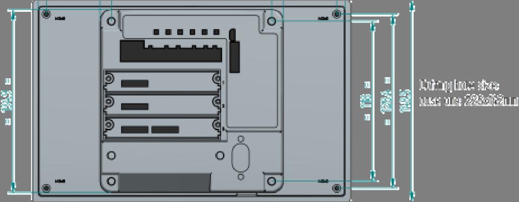

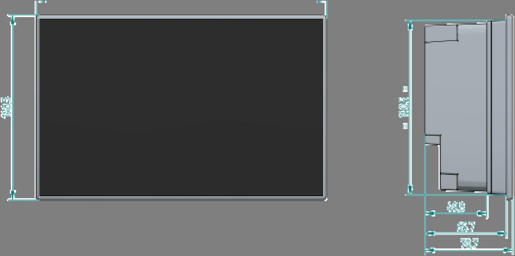

35 12 Dimensional drawings OMC-140 Operators Manual Page 35
36 13 Menu structure Touch screen General Opens settings menu Dimming Control: Manual Automatic NMEA DDC Sensor selection: Auto Sensor 1 Sensor 2 Average (Wind only) 10 minute 2 minute Instant User (settings from User Average Interval) Wind Speed (Wind only) Bft Mph m/s kn km/h Wind Reference (Wind only) Relative Theoretical True User Average Interval (Wind only) Wind Speed Wind Direction Gust Wind Variation OMC-140 Operators Manual Page 36
37 Advanced Keypad 085 Shows Operator available codes 0851 Terminal input Terminal input 2 Offset Sensor 1 Offset Sensor 2 (Wind only) (Wind only) Display Mode Landscape Portrait Marked Discontinuity (On / Off) Wind Alarm (On / Off) Wind Alarm (settings) (Wind only) (Wind only) (Wind only) Wind Alarm Pre Alarm Hysteresis Alarm Delay Output Baudrate Secure User Items Average (un)lock (Wind only) Wind Speed (un)lock (Wind only) Dimming Control (un)lock Sensor Selection (un)lock Wind Reference (un)lock (Wind only) System Name Edit GPS names (GPS only) (GPS only) Options Displays installed option boards Info Displays System & Product info. Front (only visible in Advanced Menu) OMC-140 Operators Manual Page 37
38 Edit data fields in Front screen Sensors (only visible in Advanced Menu) NMEA VER Message Table OMC-140 Operators Manual Page 38
39 14 Appendix: Declaration of Conformity OMC-140 Operators Manual Page 39
APPLICATION NOTES. WIND MEASURING SYSTEMS using XDi-N indicators. Document no.: B
 APPLICATION NOTES WIND MEASURING SYSTEMS using XDi-N indicators Document no.: 4189350080B Table of contents GENERAL INFORMATION... 4 WARNINGS, LEGAL INFORMATION AND SAFETY... 4 LEGAL INFORMATION AND DISCLAIMER...
GNX 20/21. Owner s Manual
 GNX 20/21 Owner s Manual Table of Contents Introduction...1 Device Overview... 1 Using the Race Timer... 1 Profiles... 1 Selecting a Profile... 1 Restoring Profiles to their Default Settings... 1 Instrument
GNX 120/130. Owner s Manual
 GNX 120/130 Owner s Manual March 2016 190-01846-00_0B All rights reserved. Under the copyright laws, this manual may not be copied, in whole or in part, without the written consent of Garmin. Garmin reserves
GNX 20/21. Owner s Manual
 GNX 20/21 Owner s Manual March 2016 190-01659-00_0C All rights reserved. Under the copyright laws, this manual may not be copied, in whole or in part, without the written consent of Garmin. Garmin reserves
Actual Size. WX Series Ultrasonic WeatherStation Instruments
 fpo www.busse-yachtshop.de info@busse-yachtshop.de Actual Size WX Series Ultrasonic WeatherStation Instruments AIRMAR s best-in-class, all-in-one solution for real-time, site-specific weather information
GNX 20/21 Owner s Manual
 GNX 20/21 Owner s Manual February 2014 190-01659-00_0B Printed in Taiwan All rights reserved. Under the copyright laws, this manual may not be copied, in whole or in part, without the written consent of
INSTALLATION INSTRUCTIONS AND REFERENCE HANDBOOK
 INSTALLATION INSTRUCTIONS AND REFERENCE HANDBOOK APPLICATION NOTES WIND MEASURING SYSTEMS Document no.: 4189340577BC SW version AGC 3.4X0.X0 or later and AGC 4.00.0 or later Document no.: 4189350050A Table
Race Screen: Figure 2: Race Screen. Figure 3: Race Screen with Top Bulb Lock
 Eliminator Competition Stand Alone Mode - Instruction Manual Main Menu: After startup, the Eliminator Competition will enter the Main Menu. Press the right/left arrow buttons to move through the menu.
PART 5 - OPTIONS CONTENTS 5.1 SYSTEM EXPANSION 5-3
 PART 5 - OPTIONS CONTENTS Para Page 5.1 SYSTEM EXPANSION 5-3 5.2 SENSORS 5-3 5.2.1 Trim Angle Sensor 5-3 5.2.2 Mast Rotation Sensor 5-3 5.2.3 Heel Angle Sensor 5-3 5.2.4 Barometric Pressure Sensor 5-3
CONSOLE-320 ENGLISH. 230A: CONSOLE-320 with cable data output Item 230B: CONSOLE-320 with cable + wireless radio data output
 CONSOLE-320 Item 230A: CONSOLE-320 with cable data output Item 230B: CONSOLE-320 with cable + wireless radio data output Table of contents 1. INTRODUCTION...2 1.1 Power supply...2 1.2 Connections...2 1.3
ECL Comfort 110, application 131 (valid as of software version 2.00)
") Operating Guide ECL Comfort 110, application 131 (valid as of software version 2.00) English version www.danfoss.com How to navigate? Adjust temperatures and values. Switch between menu lines. Select /
Operating Guide ECL Comfort 110, application 131 (valid as of software version 2.00) English version www.danfoss.com How to navigate? Adjust temperatures and values. Switch between menu lines. Select /
Remote Control Bait Boat
 CARPIO 2.0 User Manual All pictures shown are for illustration purpose only. Actual product may vary due to product enhancement Remote Control Bait Boat (Smart Remote Control at 868 MHz) 1 Table of Contents
Precision pressure sensor Basic version Model CPT6020
 Calibration Precision pressure sensor Basic version Model CPT6020 WIKA data sheet CT 25.13 Applications Calibration technology High-accuracy pressure monitoring Pressure sensing in critical applications
BAPI Pressure Line of Products - FAQs
 Table of Contents 1. Several manufacturers produce pressure transmitters, why should I purchase from BAPI?... p. 2 2. BAPI makes several styles of pressure transmitters. What are the features of each?...
Specifications and information are subject to change without notice. Up-to-date address information is available on our website.
 www.smar.com Specifications and information are subject to change without notice. Up-to-date address information is available on our website. web: www.smar.com/contactus.asp LD302 - AssetView HMI LD302
ACV-10 Automatic Control Valve
 ACV-10 Automatic Control Valve Installation, Operation & Maintenance General: The Archer Instruments ACV-10 is a precision automatic feed rate control valve for use in vacuum systems feeding Chlorine,
HUMOR 20. High-precision Humidity Calibrator HUMOR 20. Operation
 High-precision Humidity Calibrator The role of humidity calibrations that are accurate, reproducible, and documentable is becoming more and more important. ISO quality guidelines and regulations according
Pneumatic high-pressure controller Model CPC7000
 Calibration technology Pneumatic high-pressure controller Model CPC7000 WIKA data sheet CT 27.63 Applications Healthcare and avionics industry Industry (laboratory, workshop and production) Transmitter
Multifunction Altimeter/Variometer AV1
 Multifunction Altimeter/Variometer AV1 Revision#3.0, 21/11/2014 For firmware version 2.2 Page intentionally left blank SECTIONS MECHANICAL INSTALLATION ELECTRICAL INSTALLATION USE OF THE INSTRUMENT INSTRUMENT
Pneumatic high-pressure controller Model CPC7000
 Calibration technology Pneumatic high-pressure controller Model CPC7000 WIKA data sheet CT 27.63 Applications Automotive and avionics industry Industry (laboratory, workshop and production) Transmitter
BUBBLER CONTROL SYSTEM
 BUBBLER CONTROL SYSTEM Description: The HDBCS is a fully automatic bubbler system, which does liquid level measurements in water and wastewater applications. It is a dual air compressor system with, air
Installation and Operation Manual
 Manual Static pressure transducer with controller Differential static pressure transducer with analog output and optional PI control mode Large diaphragm element with differential transformer Transducer
2. USER INSTRUCTION. Table of contents: Pg.1/14 N:\FAP-2000: LWP
 Pg.1/14 2. USER INSTRUCTION. Table of contents: 2.1 SHORT PANEL DESCRIPTION...... Pg.2 2.2 AUTOPILOT TAKE-OVER & MODE SELECTION....... Pg.3 2.3 AUTOPILOT FUNCTIONS....... Pg.3 2.4 THE SPECIAL FUNCTION
Doppler current meter
 JLN-652 Doppler current meter JRC's new 240 khz Doppler current meter: the smartest way to increase your catch Unique 3D twist mode presentation Measuring up and down current 50 independent measuring layers
Hydro-Control V User Guide
 Hydro-Control V User Guide Hydronix Part no: HD0193 Version 2.3.0 Revision date: July 2006 1 COPYRIGHT Neither the whole or any part of the information contained in nor the product described in this documentation
Description of Device Parameters Proline Prowirl 200 HART. Vortex flowmeter. Products Solutions Services. Main menu Language.
 GP01019D/06/EN/02.15 71308256 Valid as of version 01.02.zz (Device firmware) Products Solutions Services of Device Parameters Proline Prowirl 200 HART Vortex flowmeter XXXXXXXXX 20.50 Main menu 0104-1
iregatta User Manual
 iregatta User Manual iregatta User Manual This manual may not always be up to date with the latest version of iregatta available in Apples App Store, as minor additions or bug fixes may be published without
TECNAUTIC_GmbH. Display Functions with the PB100/200 connected: -- GND Speed -- GND Course -- Heading (Gyro option is recommended) 2 m
 2 m") PB100/200 Sonic Wind Wind, GPS, Compass Display Config: SE=12 di=00 df=20,91,30,34,(61) 35,36,81 Gr=01 n0=00 n1=07 n2=07**) n3=00 Display Functions with the PB100/200 connected: -- Apparent Wind -- True
PB100/200 Sonic Wind Wind, GPS, Compass Display Config: SE=12 di=00 df=20,91,30,34,(61) 35,36,81 Gr=01 n0=00 n1=07 n2=07**) n3=00 Display Functions with the PB100/200 connected: -- Apparent Wind -- True
JOLLY2. Installation user s manual. 6 different operating modes selectable. version 3.3. DATA TO BE FILLED OUT BY THE INSTALLER (Page 1)
") ENGLISH ENGLISH ENGLISH ENGLISH Installation user s manual Warning! electrical scheme modified JANUARY 2005 version 3.3 JOLLY2 DATA TO BE FILLED OUT BY THE INSTALLER (Page 1) 6 different operating modes
ENGLISH ENGLISH ENGLISH ENGLISH Installation user s manual Warning! electrical scheme modified JANUARY 2005 version 3.3 JOLLY2 DATA TO BE FILLED OUT BY THE INSTALLER (Page 1) 6 different operating modes
Heavy Duty Dissolved Oxygen Meter
 User's Manual Heavy Duty Dissolved Oxygen Meter Model 407510 Test Equipment Depot - 800.517.8431-99 Washington Street Melrose, MA 02176 FAX 781.665.0780 - TestEquipmentDepot.com Introduction Congratulations
Optical Dissolved Oxygen Meter
 Optical Dissolved Oxygen Meter HI764113 Rugged Optical Dissolved Oxygen Probe for Fresh and Saltwater Applications Digital, weighted probe No membranes No electrolytes No oxygen consumption No flow dependence
Datasheet: K-30 ASCII Sensor
 Datasheet: K-30 ASCII Sensor The K30 ASCII sensor is a low cost, infrared and maintenance free transmitter module intended to be built into different host devices that require CO2 monitoring data. The
USER MANUAL. Intelligent Diagnostic Controller IDC24-A IDC24-AF IDC24-AFL IDC24-F IDP24-A * IDP24-AF * IDP24-AFL * IDP24-F * 1/73
 USER MANUAL Intelligent Diagnostic Controller IDC24-A IDC24-AF IDC24-AFL IDC24-F IDP24-A * IDP24-AF * IDP24-AFL * IDP24-F * *) Require software ID: DID-SW-001 1/73 Table of contents 1 General... 3 1.1
Helium Level Measurement Unit
 Helium Level Measurement Unit HLMU User Manual Version 002 The information in this manual may be altered without notice. BRUKER BIOSPIN accepts no responsibility for actions taken as a result of use of
BUBBLER CONTROL SYSTEM
 BUBBLER CONTROL SYSTEM Description: The LDBCS is a fully automatic bubbler system, which does liquid level measurements in water and wastewater applications. It is a dual air compressor system with, air
Control units. Installation and operating instructions Series: DP-Control
 Control units Installation and operating instructions Series: DP-Control Table of Contents 1 Manual introduction 1.1 Preface... 4 1.2 Icons and symbols... 4 2 Identification, service and technical support
BAROMETER PRESSURE STANDARD PRESSURE CONTROLLER
 BAROMETER PRESSURE STANDARD PRESSURE CONTROLLER Features ±0.01% FS Measurement & Control Accuracy ±0.001% /ºC Thermal Stability Pressure Ranges from ±1 psid to 1200 psia Applications Barometric Measurement
IDL01. Battery Powered Precision Digital Gauge for Leak Testing. Stainless Steel Sensor. class 0.05
 IDL0 Battery Powered Precision Digital Gauge for Leak Testing Stainless Steel Sensor class 0.05 Nominal pressure from 0 00 mbar up to 0... 00 bar Special characteristics modular sensor concept data logger
Sprayer Station PRODUCT MANUAL
 Sprayer Station PRODUCT MANUAL Item # 3349SSH Contents Introduction 3 Components 3 Installing the Station 4 Replacing the Humidity Sensor 12 Installing SpecWare Mobile Software 13 Configuring the WatchDog
TH-1800-T TRX-700-CNG Converter
 TH-1800-T TRX-700-CNG Converter low detector The CNG fuel gas flowmeter is so accurate as to meet a demand of measuring the CNG directly by making the most use of our well-established mini-thermal flowmeter
Gas Analyzer for TC Sensors (CO2, H2, N2) Series 62101, 64101, Operating Manual
 Series 62101, 64101, Operating Manual") Gas Analyzer for TC Sensors (CO2, H2, N2) Series 62101, 64101, 65101 Operating Manual Disclaimer Please read and understand the user manual before installing and using the products described herein. It
Gas Analyzer for TC Sensors (CO2, H2, N2) Series 62101, 64101, 65101 Operating Manual Disclaimer Please read and understand the user manual before installing and using the products described herein. It
DM01. Please visit our website: Battery Powered Precision Digital Gauge. Stainless Steel Sensor. class 0.05
 DM0 Battery Powered Stainless Steel Sensor class 0.05 Nominal pressure from 0 00 mbar up to 0... 00 bar Special characteristics modular sensor concept data logger graphic display stainless steel housing
300C/ 800C/ 990C Plus Series
 Ultrasonic Level Meter 300C/ 800C/ 990C Plus Series INSTRUCTION MANUAL (July, 2008) 1 SLM300C/ 800C/ 990C Plus Series July, 2008 Copyright IS Technologies Co., Ltd. All rights reserved. No part of this
HyperSecureLink V6.0x User Guide
 HyperSecureLink V6.0x User Guide Note: This software works with the LS-30 Version (06.0x or later) 1, Hardware Installation: 1-1, Connection Diagram for USB or RS-232 Computer Interface To LS-30 CM1 To
ETd 04. Battery Powered Precision Digital Gauge. Stainless Steel Sensor. Type: ETd 04. class 0.05
 Battery Powered Stainless Steel Sensor class 0.05 Nominal pressure from 0 100 mbar up to 0... 400 bar Special characteristics modular sensor concept data logger graphic display stainless steel housing
Electronic gas volume corrector model DGVC-04
 Electronic gas volume corrector model DGVC-04 1. Introduction The following user s manual gives information about the installation, configuration, usage and storage of the electronic gas volume corrector
CCT-7320/ROC-2313 Reverse Osmosis Controller
 CCT-7320/ROC-2313 Reverse Osmosis Controller 1 General The instrument is a combined control instrument of a reverse osmosis controller and an on-line conductivity instrument. It can perform the operation
APA software instruction manual
 1. Starting the program In order to start the control software for the APA device press APAxx shortcut located on the desktop of the supplied computer. XX corresponds to the current software version. When
Digital deadweight tester Model CPD8500
 Calibration technology Digital deadweight tester Model CPD8500 WIKA data sheet CT 32.05 Applications Calibration laboratories Avionics/ Aerospace equipment manufacturers Precision pressure sensor manufacturers
Digital dead-weight tester Model CPD8500
 Calibration Digital dead-weight tester Model CPD8500 WIKA data sheet CT 32.05 Applications Calibration laboratories Avionics/Aerospace equipment manufacturers Precision pressure sensor manufacturers Calibration
HUMOR 20. High Accuracy Humidity Calibrator. Water T, p1 HUMOR 20 V1.0
 High Accuracy Humidity Calibrator The role of humidity calibrations that are accurate, reproducible, and documentable is becoming more and more important. ISO quality guidelines and regulations according
A180 DO/BOD/OUR/SOUR Meter Instruction Manual
 A180 DO/BOD/OUR/SOUR Meter Instruction Manual BANTE INSTRUMENTS CO., LTD A180 DO/BOD/OUR/SOUR Meter 1 Introduction Thank you for selecting the A180 multiparameter dissolved oxygen meter. This manual provides
Controller for boilers Galan - regulator for management of heating elements and circuit SolarSentinel-DBTW User guide
 Controller for boilers Galan - regulator for management of heating elements and circuit SolarSentinel-DBTW User guide SHORT DESCRIPTION: 1. Device is applicable to: Burners, Electric boiler, Electric heaters,
ClubHub. User s Guide
 ClubHub User s Guide Table of Contents Setup... Initial Club Setup...7 Changing Clubs...5 Settings...8 My Clubs... Turn On/Off Sounds...9 Play Round Mode...0 List View...8 Social Sharing...0 Viewing D
Atlas 6TM. Indoor Air Quality Monitor Instruction Manual. Measures CO 2, Temperature and Humidity DISTRIBUTED BY
 Atlas 6TM Indoor Air Quality Monitor Instruction Manual Measures C 2, Temperature and Humidity DISTRIBUTED BY INTRDUCTIN Thank you for purchasing this meter. This device measures ppm levels, temperature
WIND CLIPPER KTS ILLUM SCALE INC DEC CLIPPER WIND SYSTEM
 CLIPPER WIND KTS ILLUM SCALE DEC INC CLIPPER WIND SYSTEM TABLE OF CONTENTS INTRODUCTION PRE-TEST OF INSTRUMENT INSTALLING THE MASTHEAD SENSOR UNIT INSTALLING THE DISPLAY NORMAL OPERATION CHANGING THE
DM01. Battery Powered Precision Digital Gauge. Stainless Steel Sensor. class 0.05
 Battery Powered Stainless Steel Sensor class 0.05 Nominal pressure from 0 00 mbar up to 0... 00 bar Special characteristics modular sensor concept data logger graphic display stainless steel housing Ø
BI-680 Online Dissolved Oxygen Controller Instruction Manual
 BI-680 Online Dissolved Oxygen Controller Instruction Manual BANTE INSTRUMENTS CO., LTD BI-680 Online Dissolved Oxygen Controller 1 Introduction Thank you for selecting the BI-680 online dissolved oxygen
Instruction Manual BA90 Precision Barometer
 Instruction Manual BA90 Precision Barometer halstrup-walcher GmbH Stegener Straße 10 D-79199 Kirchzarten Germany Phone: +49 (0) 76 61/39 63 0 Fax: +49 (0) 76 61/39 63 99 E-Mail: info@halstrup-walcher.com
LX Compass module 3 Electronic compass device User manual
 LX Compass module 3 Electronic compass device User manual LX navigation d.o.o., Tkalska 10 SLO 3000 Celje, tel: + 386 3 490 46 70, fax: + 386 3 490 46 71 info@lxnavigation.si, http://www.lxnavigation.com
GHC 20. Owner s Manual
 GHC 20 Owner s Manual 2013 Garmin Ltd. or its subsidiaries All rights reserved. Under the copyright laws, this manual may not be copied, in whole or in part, without the written consent of Garmin. Garmin
S100 Controller. User guide. English Date: Document number: EN 2006 Raymarine UK Limited
 S100 Controller User guide English Date: 06-2006 Document number: 81242-4-EN 2006 Raymarine UK Limited 1 - Getting Started Changing the Controller batteries... 5 The S100 Autopilot Controller... 6 How
WELCOME TO THE REVOLUTION
 USER GUIDE WELCOME TO THE REVOLUTION THANK YOU FOR CHOOSING THE GCQUAD We listened to what you wanted - and created the most accurate, versatile and game-enhancing ball and club analysis solution available
Manual Weighingblock VB2 series and Uniscale
 Manual Weighingblock VB2 series and Uniscale Note: At page 8 in this manual you will find a short form instruction. Normally the only instruction shipped together with the Scale. Overview different ranges.
The HumiSys. RH Generator. Operation. Applications. Designed, built, and supported by InstruQuest Inc.
 The HumiSys RH Generator Designed, built, and supported by InstruQuest Inc. Versatile Relative Humidity Generation and Multi-Sensor System The new HumiSys with single or dual RH probes capabilities is
CONTROL LOGIC DESCRIPTION DOCUMENT IC-410ND
 Configuration # : 41G20F0 CONTROL LOGIC DESCRIPTION DOCUMENT IC-410ND Input/output table: Inputs Qty Outputs Qty Inside Temperature Probe 3 Inflatable Balloon 8 Chimney Temperature Probe 1 Chimney Activator
Bante821 Portable Dissolved Oxygen Meter Instruction Manual
 Bante821 Portable Dissolved Oxygen Meter Instruction Manual BANTE INSTRUMENTS CO., LTD Bante821 Portable Dissolved Oxygen Meter 1 Introduction Thank you for selecting the Bante821 portable dissolved oxygen
AIR FLOW ANEMOMETER INSTRUCTION MANUAL
 AIR FLOW ANEMOMETER INSTRUCTION MANUAL Thank you for purchasing our company Air Flow Anemometer. This manual provides relative information on how to use the Air Anemometer and warning in operation Please
Electronic Volume Correctors
 Electronic Volume Correctors Ben Manson Landis+Gyr October 14, 2016 PUBLIC Agenda Customer Types and suitable equipment Volume corrector standards / regulations Basics of volume correction Gauge v Absolute
GHC 20 Owner s Manual
 GHC 20 Owner s Manual Introduction See the Important Safety and Product Information guide in the product box for product warnings and other important information. You are responsible for the safe and prudent
Safety Manual VEGAVIB series 60
 Safety Manual VEGAVIB series 60 Contactless electronic switch Document ID: 32002 Contents Contents 1 Functional safety... 3 1.1 General information... 3 1.2 Planning... 4 1.3 Adjustment instructions...
LEVIFLOW INTEGRATED FLOWMETER LFIF USER MANUAL
 LEVIFLOW INTEGRATED FLOWMETER LFIF USER MANUAL LEVIFLOW Integrated Flowmeter: LFIF-06 (10 l/min) This manual contains information necessary for the safe and proper use of the LEVIFLOW LFS flowmeter series.
STX 165 Operation. Data Knob Enter Pushbutton. Power/Mode Control. Select Knob Ident Pushbutton. VFR Pushbutton
 STX 165 Operation The STX 165 is a Mode C transponder capable of transmitting 4076 different codes in response to ground radar interrogations. All operations of the STX 165 are controlled through the front
PTG100 Precision Test Gauge
 PTG100 Precision Test Gauge User Manual PD1007 Rev B 03/28/2014 Palmer Instruments Inc. 234 Old Weaverville Road Asheville, NC 28804 Toll Free: 800-421-2853 Phone: 828-658-3131 Fax: 828-658-0728 Email:
Industrial pressure controller Model CPC4000
 Calibration technology Industrial pressure controller Model CPC4000 WIKA data sheet CT 27.40 Applications Oil and gas industry Industry (laboratory, workshop and production) Transmitter and pressure gauge
Safety Manual VEGAVIB series 60
 Safety Manual VEGAVIB series 60 NAMUR Document ID: 32005 Contents Contents 1 Functional safety... 3 1.1 General information... 3 1.2 Planning... 4 1.3 Adjustment instructions... 6 1.4 Setup... 6 1.5 Reaction
Temperature Controller CC24-7 ULTRA USER S MANUAL Legion Dr. Mason, MI USA October 2010 Ph. (517) Fax (517)
 Fax (517)") Temperature Controller USER S MANUAL Aerotech, Inc. FORM: QM1387 4215 Legion Dr. Mason, MI 48854-1036 USA October 2010 Ph. (517) 676-7070 Fax (517) 676-7078 FOR CUSTOMER USE Enter the serial number located
Temperature Controller USER S MANUAL Aerotech, Inc. FORM: QM1387 4215 Legion Dr. Mason, MI 48854-1036 USA October 2010 Ph. (517) 676-7070 Fax (517) 676-7078 FOR CUSTOMER USE Enter the serial number located
Optical Dissolved Oxygen Meter
 Optical Dissolved Oxygen Meter HI764113 Rugged Optical Dissolved Oxygen Probe for Fresh and Saltwater Applications Digital probe Fast and stable readings No membranes Not affected by sunlight No electrolytes
Instruction Manual AD 1000 / BA 1000 Absolute Pressure Sensor
 Instruction Manual AD 1000 / BA 1000 Absolute Pressure Sensor halstrup-walcher GmbH Stegener Straße 10 D-79199 Kirchzarten Phone: +49 (0) 76 61/39 63 0 Fax: +49 (0) 76 61/39 63 99 E-Mail: info@halstrup-walcher.com
A4s Operation Manual
 A4s Operation Manual Safety Instruction Please read this manual carefully, also with related manual for the machinery before use the controller. For installing and operating the controller properly and
RESOLUTION MSC.94(72) (adopted on 22 May 2000) PERFORMANCE STANDARDS FOR NIGHT VISION EQUIPMENT FOR HIGH-SPEED CRAFT (HSC)
 (adopted on 22 May 2000) PERFORMANCE STANDARDS FOR NIGHT VISION EQUIPMENT FOR HIGH-SPEED CRAFT (HSC)") MSC 72/23/Add.1 RESOLUTION MSC.94(72) EQUIPMENT FOR HIGH-SPEED CRAFT (HSC) THE MARITIME SAFETY COMMITTEE, RECALLING Article 28(b) of the Convention on the International Maritime Organization concerning
MSC 72/23/Add.1 RESOLUTION MSC.94(72) EQUIPMENT FOR HIGH-SPEED CRAFT (HSC) THE MARITIME SAFETY COMMITTEE, RECALLING Article 28(b) of the Convention on the International Maritime Organization concerning
BathySurvey A Trimble Access hydrographic survey module
 BathySurvey A Trimble Access hydrographic survey module Contents 1. Introduction... 3 2. Installation... 4 3. Main Screen... 5 4. Device... 6 5. Jobs... 7 6. Settings Odom Echotrac... 8 7. Settings Ohmex
GNX Wind. Owner s Manual
 GNX Wind Owner s Manual February 2016 190-02003-00_0A All rights reserved. Under the copyright laws, this manual may not be copied, in whole or in part, without the written consent of Garmin. Garmin reserves
WeatherStation Monitoring for Industrial marine Applications
 WeatherStation Monitoring for Industrial marine Applications PB200 WeatherStation Instrument Applications: Industrial marine weather monitoring Features: True and Apparent Wind Speed and Direction Barometric
Touch Screen Guide. OG-1500 and OG Part # T011
 Touch Screen Guide OG-1500 and OG-2000 Part # 9000000.T011 Effective 11/2010 External View Internal View 1. Transducer Banks 2. Oxygen Sensor 3. PLC These are the two manifolds with three (3) transducers
WF STEUERUNGSTECHNIK GMBH. INFORMATION and TECNICAL DESCRIPTION
 1 INFORMATION and TECNICAL DESCRIPTION 14 2 AIRLEADER Professional Compressor Management + Compressed Air Visualisation + Alarm Service Management + AIRLEADER - has been the effective answer for compressed
RM-80 respiration monitor
 RM-80 respiration monitor User Manual September 18, 2015 0025-003M 950 North Hague Avenue Columbus, Ohio 43204-2121 USA Sales: sales@colinst.com Service: service@colinst.com Phone: (614) 276-0861 Fax:
PRODUCT MANUAL. Diver-MOD
 PRODUCT MANUAL Diver-MOD Contents 1 Introduction... 1 1.1 Scope and Purpose... 1 1.2 Features... 1 1.3 System Overview... 1 1.4 Specifications... 2 2 Getting Started... 2 2.1 Supported Equipment... 2 2.2
OPERATION AND INSTALLATION MANUAL
 AP46 Autopilot OPERATION AND INSTALLATION MANUAL www.tmq.com.au TMQ AP46 Autopilot Page 1 of 34 Ver1.0 07/03/2007 This page is Blank TMQ AP46 Autopilot Page 2 of 34 Ver1.0 07/03/2007 WARNING!...4 INTRODUCTION...5
ACI_Release_Notes.txt VERSION Fixed Tank info for ELITE in Dive section 2. Fixed USB port initializing for old DC VERSION
 VERSION 2.4.0 1. Fixed Tank info for ELITE in Dive section 2. Fixed USB port initializing for old DC VERSION 2.3.9 1. Fixed Dive Computer configuration section error 2. Fixed message for download/upload
MEGAS 2.0. Gas analysis with direct C-Level Calculation and Bus-Connection. Data sheet
 Data sheet MEGAS 2.0 Gas analysis with direct C-Level Calculation and Bus-Connection Mesa Industrie-Elektronik GmbH Neckarstraße 19, D-45768 Marl info@mesa-gmbh.de +49 (0) 2365-97 45 1-0 +49 (0) 2365-97
WIND. - Instrument - Installation and Operation Manual English
 - Instrument - Installation and Operation Manual 1 Introduction Thank you for choosing Star Wind instrument. We are convinced that you will appreciate all the valuable information either you are a cruiser
HumiSys HF High Flow RH Generator
 HumiSys HF High Flow RH Generator Designed, built, and supported by InstruQuest Inc. Versatile Relative Humidity Generation and Multi-Sensor System The HumiSys HF is a high flow version of the previously
A4 Operation Manual. Fig.1-1 Controller Socket Diagram
 A4 Operation Manual Safety Instruction Please read this manual carefully, also with related manual for the machinery before use the controller. For installing and operating the controller properly and
Special Documentation Proline Promass 80, 83
 SD00077D/06/EN/14.14 71272498 Products Solutions Services Special Documentation Proline Promass 80, 83 Functional safety manual Coriolis mass flow measuring system with 4 20 ma output signal Application
Industrial pressure controller Model CPC4000
 Calibration technology Industrial pressure controller Model CPC4000 WIKA data sheet CT 27.40 Applications Oil and gas industry Industry (laboratory, workshop and production) Transmitter and pressure gauge
Hand-held pressure calibrator with integrated pump Model CPH6600
 Calibration technology Hand-held pressure calibrator with integrated pump Model CPH6600 WIKA data sheet CT 16.01 Applications Calibration service companies and service industry Measurement and control
ECHO MANUAL WARNING. L B A ltim e te rs. ECHO is a trademark of LB Altimeters, Denmark
 ECHO MANUAL L B A ltim e te rs ECHO is a trademark of LB Altimeters, Denmark LB Altimeters operates a policy of continuous development Therefore, we reserve the right to make changes and improvements to
Operating Instructions METTLER TOLEDO Pipette Check Application for AX and MX/UMX Balances Version 1.xx
 Operating Instructions METTLER TOLEDO Pipette Check Application for AX and MX/UMX Balances Version 1.xx Contents 1 Introducing the Pipette Check application... 3 2 important notes... 3 3 Selecting the
Roller AC Servo System
 Safely Instruction Roller AC Servo System HMI-15 User Manual Please read this manual carefully, also with related manual for the machinery before use the controller. For installing and operating the controller