Airframes. Chapter 5: Wings & Tailplane
|
|
|
- Sarah Warren
- 5 years ago
- Views:
Transcription


1 Airframes Chapter 5: Wings & Tailplane 1
2 2
3 Learning Objectives The purpose of this chapter is to discuss in more detail, 2 of the 4 major components, the Wing (or mainplane) and the Tailplane. By the end of the lesson you should have an understanding of the main functions of this most important of the main components of an aircraft, as well as it s construction. But first a recap of Chapter 4 with some questions. 3
4 Chapter 4 Revision A few questions about the previous chapter. 1. Why are windows elliptical? 2. What is a Welded Steel Truss? 3. Why do we pressurise the fuselage? 4. What parts of a Combat Aircraft are pressurised? 4
5 The Wing From Principles of Flight, you will know that to fly, an aircraft must have wings designed to generate lift from the airflow over them. To take off and climb, the wings must produce more lift than the aircraft s total weight. For an aircraft such as the Airbus A380, which weighs 550 tonnes, this is no mean task. If a fighter aircraft was to fly in a very tight turn, the wings must then produce lift equal to perhaps eight times the aircraft weight. 5
6 The Wing For level flight the lift produced must equal the aircraft s weight. For landing, where the slowest possible landing speed is required, enough lift must be produced to keep the aircraft flying at low speeds. For this it will normally have special devices added - flaps, leading-edge slats The shape of the aircraft is extremely important, because it dictates how well the aircraft can does its job. For a slow-flying aircraft which needs to lift heavy loads, a large wing is needed, together with a fairly light structure. For fast jets, a much smaller wing is required, and the aircraft will be more streamlined. 6
7 Wing Loading One of the most important factors in an aircraft design is its wing loading, which is simply its weight divided by its wing area. The weight of the aircraft can vary, both with the load it is carrying and as a result of flight manoeuvres Flying at 4g in a turn increases an aircraft s effective weight to four times its normal weight, so its wing loading will change. A useful guide is to use the maximum take-off weight (MTOW) to calculate a standard wing loading. Light aircraft will normally have the lowest wing loading, and fast jets the highest, with transport aircraft in between. 7

8 Design Considerations For aircraft flying at, or near supersonic speeds, the way in which air flows over the aircraft is very different, and can create problems. An aircraft flying quite slowly through the air generates pressure waves, which move at the speed of sound. At speeds near the speed of sound a shock wave forms on the leading parts of the aircraft. The air behind this shock wave becomes turbulent, causing loss of lift, increased drag, changes in trim and buffeting of controls. 8
9 Sweep-Back The Solution Designers can reduce the effects of these problems with better designs, particularly swept-back wings. However, these features can cause other problems, because they are more difficult and expensive to build. Once above the speed of sound, the airflow is steady again, although different to subsonic conditions. The curved shapes that worked well at lower speeds are no longer the most efficient, and straight lines and sharp edges are now preferred. 9
10 Wing Planform The planform of wings becomes more important than their section, and low aspect ratio and sharper sweepback may be necessary. The main disadvantage of swept-back wings is that they produce much less lift than an un-swept wing of the same area and aspect ratio. This means that when the aircraft is flying slowly, for instance during landings, a larger angle of attack is required to provide enough lift. This can cause problems with landing gear and in pilot visibility. 10


11 Swing Wings Being able to change the amount of sweepback in flight would be a way towards getting the best in both situations. This has been done on many high speed military aircraft In the swept forward position it gives high aspect ratio wing for low-speed performance, allowing tight turns at low speeds and making flaps more effective for take-off and landing. In the swept back position, it is highly suited to high-speed flight. 11
12 Delta Wings Another option for aircraft which need to fly at high speeds but also need to be able to turn tightly at all speeds is the delta wing. This has the advantage of high sweepback, but the trailing edge is more suited to fitting effective flaps. Because of the aerodynamics of delta wings, they are capable of producing lift at much higher angles of attack than other wing shapes, and so can be used on highly agile fighter aircraft. Delta wings, which went out of fashion in the 1970s and 1980s, are becoming more common. Many examples can be seen, often in conjunction with Canard Foreplanes for control. 12
13 Aspect Ratio The aspect ratio of an aircraft s wing is an important design feature, and is simply the ratio of the wing span to its average chord. This is not always simple to calculate if a wing shape is complex, so another way of defining it is; Aspect Ratio = Span2 Area So if a wing has an area of 80 square metres and a span of 20 metres the aspect ratio is (20 2 /80 = 5). It is usual to use the projected area to calculate the aspect ratio, that is, to include that part of the wing which is inside the fuselage. 13

14 Aspect Ratio - Examples High performance sailplanes have aspect ratios in the region of 25 to 30, and fighters somewhere around 5 to 10. High aspect ratio reduces the induced drag caused by air flowing around the wing tips, and is ideal where long slow flights are required. The drawback is that long, thin wings need to be heavier, and are very flexible. 14

15 Monoplanes Although there are still a few bi-planes around, most aircraft are monoplanes. This provides a very stiff, strong wing, without the drag penalty of the biplane arrangement. Many light aircraft are braced monoplanes, having a diagonal bracing tie between the wing and fuselage. This allows a lighter structure in the wing, because some of the lift load is taken by the brace. The extra drag caused is acceptable at low speeds. 15
16 Cantilever Monoplanes The cantilever wing is used for aircraft of all speeds, because it offers the lowest drag. The wings have to be strong enough and stiff enough to carry the whole weight of the aircraft, plus its aerodynamic loads, without the need for external bracing. They can be categorised as; Low Wing: Grob 115E Tutor Mid Wing: Gen Dyn F-16 High Wing: BAe Harrier GR9 16
17 Wing Functions Obviously the primary function of the wings on an aircraft are to provide the lift required to enable it to fly. However, what other functions do you think a wing is expected to do? Asyoucansee,thewingcansometimesdolotsofjobs as well as providing lift! 17

18 Flying Wings So we can see that the wings are the main component of an airframe. In fact, aircraft have been designed and built which consist only of a pair of wings like the Northrop Flying Wing. 18


19 Flying Wing Compromise A more common compromise can be seen in aircraft like the Boeing B2 Spirit, F-117A Nighthawk and delta aircraft like Concorde. 19
20 Wing Loads & Forces The wing is subject to a number of loads and forces, both whilst the aircraft is on the ground and when it is in the air. When an aircraft is moving through the air, the drag effect from the air to it s forward motion places a force on the wing. Likewise, the act of the wing in generating lift also places forces on the structure. On the ground, the weight of the fuel, undercarriage, engines, wing structure and in military aircraft weapon loads will all try and bend the wing under the force of gravity. The designer has to make the wings strong and stiff enough to resist not only the forces of lift and drag, which try to bend them upwards and backwards, but also the loads that gravity will place on the structure. 20
21 Methods of Construction As you have already seen, different sizes and types of aircraft can be constructed in different ways. This applies to the mainplanes, or wings, as much as to any other part. Can you think of component parts of the structure that make up a complete wing? 21
22 Methods of Construction Each wing is basically made up of two parts; The internal structure, such as the spars and the ribs The skin, which can be of fabric, metal or composites. Although the distinction between metal and composite wings may not be very apparent in modern fast jets or large transport aircraft. Wing construction itself comes in two forms. The modern Stress Skin standard and the older Fabric Covered wing. However, both forms of construction rely on a similar internal construction. 22
23 Fabric Covered Wings The main structural members, as for most aircraft wings, are the front and rear spars, which are attached to each other by a series of ribs. Ribs give the wing it s section, and transfer loads from the covering into the spars. Leading Edge Ribs Extra Nose Ribs Rear Spar Front Spar Trailing Edge Attached to the front spar is the leading edge section, in this case made up of nose ribs and the leading edge itself. 23
24 Fabric Covered Wings The trailing edge section is similar, but of a different shape, and contains the ailerons and flaps. Although the fabric covering takes very little load, it does strengthen and stiffen the structure a little, especially in torsion (twisting). The main structural ribs help to support the fabric to keep a good aerodynamic section along the whole wing. Along the leading edge, where the aerodynamic section curves most, extra nose ribs are added to make sure this important part of the wings is not upset by sagging of the covering fabric. 24
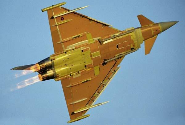
25 Stressed Skin Wings Air loads on the wing increase at the square of the speed increase. For instance, at 400 knots the air loads are four times as great as the 200 knots achieved by the fastest of light aircraft. The Eurofighter Typhoon easily reaches speeds in excess of 1200 knots. Fabric covered wings cannot meet these higher loads, and so a more rigid Stressed skin must be used. Aluminium alloys are most often used for this, but composite materials (carbon fibre) are now becoming more common. 25
26 Stressed Skin Wings Both aluminium alloy and composite provide a smoother finish and more contour to the shape than a fabric covering,butifitisverythinitdoesnotgivemuchextra strength. If the skin is thicker, it can share the loads taken by the structure underneath, which can then be made lighter. Almost all aircraft have their structure made entirely in metal, or a mixture of metal and composite materials. The main spars are still the main strength members, but a large contribution to the strength is made by the skin. 26
27 Stressed Skin Construction InaStressedSkinwing,thewholewingisnormallyof metal construction, although the wing tip, ailerons and leading edge may be of composites. As the use of composites increase, more and more of the airframe will be made this way. To reduce weight the ribs (both metallic and composite) may have large lightening holes, with flanged edges to keep the required stiffness. The skin may be fixed to the internal structure by rivets and bolts, as shown on the following diagram, or by bonding (gluing), using special adhesives. 27

28 Stiffening Stringers The stressed wing skin must be stiffened to prevent buckling between the ribs. A simple solution is to add stringers which would be bonded or riveted to them, or integrally machined. Stringers to stiffen the skin 28
29 Question? So with all that structure, what do you think the space between the front and rear spar could be used for on this type of wing? The volume between the front and rear spars is often used for storing fuel, and holes in the ribs allow the fuel to flow inside this space. 29
30 Leading & Trailing Edges There are also spaces in the leading and trailing edges i.e. in front of and behind the spars. What do you think could be put in these spaces? Other Equipment The leading- and trailing-edge sections are used for carrying electrical cables, control wires and other items along the wing. 30
31 So Why Choose Stressed Skin? Stressed skin wing construction is generally chosen as it allows thin cantilever wings to be produced. These are strong enough to resist the tension, compression and twisting loads caused by high speeds. Therefore a wing of stressed skin construction is the ONLY option for an aircraft that travels at medium to high speeds. 31

32 Spar Design An ideal spar is given depth so it may resist the bending forces that are imposed on it. An example of this is an ordinary measuring ruler, which will flex easily when loaded on its top or bottom surfaces, but is very stiff when a load is applied to the edge. Now you try! 32

33 Typical Spar Sections Three typical spar sections are shown in pictures below. A & B are made of sections fastened together, but some modern aircraft would have the spar made from a single piece of metal, as in C, making it stronger and lighter. Of course, this means it has to be made more accurately, as no adjustments can be made during assembly. Also in examples A and B shown, the flanges could be made as part of the skin, if the skin is machined from a thicker material. 33
34 High-Speed Flight Spars However, for high-speed flight, a thin wing is needed, but it may not be possible to get a deep enough spar for the wing to cope with the stresses placed upon it. To make the wing strong enough, more than one spar will be used. Using two spars is quite usual on many aircraft and is referred to as a multi-spar wing. 34

35 Multi-Spar Wing Example Supersonic aircraft, such as the Eurofighter Typhoon, require extremely thin wings, and hence use a multi-spar layout 35

36 Torsion Box Most modern large aircraft use two main spars, with stressed skin between them, to form a torsion box construction. The example below also has a centre spar. The leading and trailing edge sections are then added in a lighter construction, and carry very little of the loads applied to the wing. The major advantage of this is that, as mentioned earlier, the space within the torsion box is an ideal space to store fuel. 36

37 Wing Assembly The whole volume is sealed using special compounds to prevent leakage, and may be divided up into several large tanks, so that the fuel may be moved around as required to balance the aircraft or reduce loads in flight. Front Spar The image to the left is of the assembly of an Airbus wide-body wing. Stringers Ribs Centre Spar Easy to see is the front and centre spars (the rear spar is not visible), the ribs and the stringers. 37

38 Airbus A320 Wing Sub-Assemblies 38
39 Machined Skin As an alternative to making stressed skins by fastening stringers to the skin (fabricated), the skin, stringers and spar flanges can all be machined from a single piece of alloy, called a billet. This billet may be many metres long, since it is possible to make the skin for one wing in a single piece. The billet is much thicker and heavier then the final machined skin. During the manufacture of the machined skin, up to 90% of the billet will be removed during machining! Although this is more expensive, in both material and machining cost, the final result is a lighter and stronger skin than a fabricated one. 39
40 Advantages of Machined Skin The advantages of using Machined Skin in an airframe design are; Riveting is no longer required, so a smoother surface can be achieved providing a better aerodynamic wing. The resultant wing has a lighter structure and a more even loading than an equivalent fabricated wing. Computer-controlled machining means mistakes or faults are less likely, and more easily detected. Allows for easy inspection during manufacture and in service. Little or no maintenance is required. Fuel spaces are easily sealed. 40
41 Disadvantages of Machined Skin However, there are some disadvantages to utilising Machined Skin in airframes The associated high cost of manufacturing particularly the tooling set-up costs Battle damage repair in combat aircraft with machined skin wings can be more difficult. Careful design is needed in order to maintain fail safety by limiting spreading of fatigue cracking. 41
42 The False Spar As they are very different in shape to other types of wing, delta and heavily swept wings have different construction to other wings. Delta wings have a very high chord at the wing root, and so thickness for structural stiffness is not a problem. Swept wings may have to house the undercarriage when it is retracted, and the sweep means that it must be located near to the trailing edge. 42

43 The False Spar A solution to this is to add another short spar (or false spar) and to increase the chord of the wing at the root. This then gives enough depth in the wing to fit the retracted undercarriage, and provides a strong point for the undercarriage mounting. Front Spar Centre Spar Rear Spar U/C Attachment False Spar 43


44 Undercarriage Attachment Additional Ribs Rear Spar Landing Gear Attachment Points False Spar 44

45 Undercarriage Attachment Rear Spar False Spar Landing Gear Attachment Points 45

46 Tailplanes on light aircraft may be built in a similar way to a fabric-covered wing. Stressed-skin tailplanes are usually similar in construction to stressedskin wings, but they are obviously smaller and usually have a different section, because they are not required to produce lift in normal flight. Tailplane 46

47 The Fin The picture on the right shows how the fin on a Harrier is constructed. As you can see, the construction of the fin is similar to that of the tailplane. The fin consists of ribs, spars and skin panels. Ribs Stressed skin Spars 47


48 Tailplane & Fin Configurations Designers have tried many different configurations of Tailplane & Fin over the years. On the right is the Tailplane &Finof a Lockheed Super Constellation. As you can see, instead of a large rudder, it has 3 smaller units. 48

49 Tailplane & Fin Configurations On large aircraft, the fin may also contain fuel. Not only does this increase the fuel capacity, but it also allows for trimming of the aircraft by transfer of weight rather than by deflecting aerodynamic control surface, and so reduces drag. Another configuration, is the T tail such as the VC-10. This is where the tailplane is mounted on top of the fin 49


50 Foreplanes Foreplanes are of similar construction to tailplanes, but are generally smaller in size. Because of their smaller size, foreplanes lend themselves to being made of composite materials They are almost always all-flying, that is, the entire foreplane moves to provide the control movements. Typhoon foreplane At Rest Typhoon foreplane At Work 50
51 Conclusions As has been seen, the wing is not only the most important part of the airframe, but it is also one of the most complex. As technology advances, so the designers of wings will create evermore efficient wings. Even so, the underlying structure of the wing has not changed in many years. Methods of constructing the wing, and the materials it is made from are the factors that are changing most. Any Questions? 51
52 Questions Here are some questions for you! 1. Name 2 parts of a wing? 2. What is an alternative to making a stressed skin by fastening stringers to the skin? 3. If an aircraft increases it s airspeed from 200 knots to 600 knots, how much higher will the air loads on the wing be? 52
BASIC AIRCRAFT STRUCTURES
 Slide 1 BASIC AIRCRAFT STRUCTURES The basic aircraft structure serves multiple purposes. Such as aircraft aerodynamics; which indicates how smooth the aircraft flies thru the air (The Skelton of the aircraft
AIRCRAFT STRUCTURAL DESIGN & ANALYSIS K. RAMAJEYATHILAGAM
 AIRCRAFT STRUCTURAL DESIGN & ANALYSIS K. RAMAJEYATHILAGAM To invent an airplane is nothing To build one is something But to fly is everything Lilienthal DAY 1 WHAT IS AN AIRCRAFT? An aircraft is a vehicle,
Theory of Flight Aircraft Design and Construction. References: FTGU pages 9-14, 27
 Theory of Flight 6.01 Aircraft Design and Construction References: FTGU pages 9-14, 27 Main Teaching Points Parts of an Airplane Aircraft Construction Landing Gear Standard Terminology Definition The airplane
Howard Torode. Member of General Aviation Group and Chairman BGA Technical Committee
 Efficient Light Aircraft Design Options from Gliding Howard Torode Member of General Aviation Group and Chairman BGA Technical Committee Presentation Aims Recognise the convergence of interest between
Aircraft Design: A Systems Engineering Approach, M. Sadraey, Wiley, Figures
 Aircraft Design: A Systems Engineering Approach, M. Sadraey, Wiley, 2012 Chapter 5 Wing Design Figures 1 Identify and prioritize wing design requirements (Performance, stability, producibility, operational
Fighter aircraft design. Aerospace Design Project G. Dimitriadis
 Fighter aircraft design Aerospace Design Project 2017-2018 G. Dimitriadis General configuration The elements of the general configuration are the following: Wing Wing placement Airfoil Number of engines
Flight Control Systems Introduction
 Flight Control Systems Introduction Dr Slide 1 Flight Control System A Flight Control System (FCS) consists of the flight control surfaces, the respective cockpit controls, connecting linkage, and necessary
Related Careers: Aircraft Instrument Repairer Aircraft Designer Aircraft Engineer Aircraft Electronics Specialist Aircraft Mechanic Pilot US Military
 Airplane Design and Flight Fascination with Flight Objective: 1. You will be able to define the basic terms related to airplane flight. 2. You will test fly your airplane and make adjustments to improve
parts of an airplane Wing Design BOX Museum Aeronautics Research Mission Directorate in a Series National Aeronautics and Space Administration
 National Aeronautics and Space Administration GRADES K-12 Wing Design Aeronautics Research Mission Directorate parts of an airplane Museum in a BOX Series www.nasa.gov MUSEUM IN A BOX (Photo courtesy of
X-29 Canard Jet. A Simple Depron Foam Build.
 X-29 Canard Jet. A Simple Depron Foam Build. Two full sized X-29 s were built and the first flew in 1984. They were experimental aircraft, testing this unusual configuration of a canard jet with swept
Jet Propulsion. Lecture-17. Ujjwal K Saha, Ph. D. Department of Mechanical Engineering Indian Institute of Technology Guwahati
 Lecture-17 Prepared under QIP-CD Cell Project Jet Propulsion Ujjwal K Saha, Ph. D. Department of Mechanical Engineering Indian Institute of Technology Guwahati 1 Lift: is used to support the weight of
Aerodynamic Terms. Angle of attack is the angle between the relative wind and the wing chord line. [Figure 2-2] Leading edge. Upper camber.
![Aerodynamic Terms. Angle of attack is the angle between the relative wind and the wing chord line. [Figure 2-2] Leading edge. Upper camber.](/thumbs/82/86661300.jpg "Aerodynamic Terms. Angle of attack is the angle between the relative wind and the wing chord line. [Figure 2-2] Leading edge. Upper camber.") Chapters 2 and 3 of the Pilot s Handbook of Aeronautical Knowledge (FAA-H-8083-25) apply to powered parachutes and are a prerequisite to reading this book. This chapter will focus on the aerodynamic fundamentals
Chapters 2 and 3 of the Pilot s Handbook of Aeronautical Knowledge (FAA-H-8083-25) apply to powered parachutes and are a prerequisite to reading this book. This chapter will focus on the aerodynamic fundamentals
ROAD MAP... D-1: Aerodynamics of 3-D Wings D-2: Boundary Layer and Viscous Effects D-3: XFLR (Aerodynamics Analysis Tool)
") Unit D-1: Aerodynamics of 3-D Wings Page 1 of 5 AE301 Aerodynamics I UNIT D: Applied Aerodynamics ROAD MAP... D-1: Aerodynamics of 3-D Wings D-: Boundary Layer and Viscous Effects D-3: XFLR (Aerodynamics
Unit D-1: Aerodynamics of 3-D Wings Page 1 of 5 AE301 Aerodynamics I UNIT D: Applied Aerodynamics ROAD MAP... D-1: Aerodynamics of 3-D Wings D-: Boundary Layer and Viscous Effects D-3: XFLR (Aerodynamics
CHAPTER 1 PRINCIPLES OF HELICOPTER FLIGHT FM 1-514
 CHAPTER 1 PRINCIPLES OF HELICOPTER FLIGHT Basic flight theory and aerodynamics are considered in full detail when an aircraft is designed. The rotor repairer must understand these principles in order to
1 General. 1.1 Introduction
 1 General 1.1 Introduction The contents of this book will focus on the anatomy of the aeroplane and the various systems that enable it to operate both on the ground and in the air. Flight controls Landing
The Fly Higher Tutorial IV
 The Fly Higher Tutorial IV THE SCIENCE OF FLIGHT In order for an aircraft to fly we must have two things: 1) Thrust 2) Lift Aerodynamics The Basics Representation of the balance of forces These act against
Aerodynamics Principles
 Aerodynamics Principles Stage 1 Ground Lesson 3 Chapter 3 / Pages 2-18 3:00 Hrs Harold E. Calderon AGI, CFI, CFII, and MEI Lesson Objectives Become familiar with the four forces of flight, aerodynamic
Stability & Control Aspects of UCAV Configurations
 Stability & Control Aspects of UCAV Configurations Paul Flux Senior Aerodynamicist BAE SYSTEMS Air Programmes Report Documentation Page Form Approved OMB No. 0704-0188 Public reporting burden for the collection
Principles of glider flight
 Principles of glider flight [ Lecture 2: Control and stability ] Richard Lancaster Email: Richard@RJPLancaster.net Twitter: @RJPLancaster ASK-21 illustrations Copyright 1983 Alexander Schleicher GmbH &
CHAPTER 9 PROPELLERS
 CHAPTER 9 CHAPTER 9 PROPELLERS CONTENTS PAGE How Lift is Generated 02 Helix Angle 04 Blade Angle of Attack and Helix Angle Changes 06 Variable Blade Angle Mechanism 08 Blade Angles 10 Blade Twist 12 PROPELLERS
Building Instructions ME 163 B 1a M 1:5 Turbine
 Building Instructions ME 163 B 1a M 1:5 Turbine Thank you for choosing our kit of the Me-163B. We ask you to read the instruction once in advance before building this kit in order to avoid mistakes. Make
Advanced Stalling. L = CL ½ ρ V 2 S. L = angle of attack x airspeed. h L = angle of attack x h airspeed. Advanced Manoeuvres
 Advanced Manoeuvres Advanced Stalling This Advanced Stalling lesson covers the factors that affect the observed airspeed and nose attitude at the stall. Although the aeroplane always stalls when the aerofoil
Bench Trimming A Stunt Ship
 Bench Trimming A Stunt Ship by Brett Buck "Bench Trimming" - this refers to setting up the initial trim of the airplane in the shop prior to flight. Since people have been flying stunt in its current form
Lift for a Finite Wing. all real wings are finite in span (airfoils are considered as infinite in the span)
") Lift for a Finite Wing all real wings are finite in span (airfoils are considered as infinite in the span) The lift coefficient differs from that of an airfoil because there are strong vortices produced
Lift for a Finite Wing all real wings are finite in span (airfoils are considered as infinite in the span) The lift coefficient differs from that of an airfoil because there are strong vortices produced
STOL CH rd Edition Drawings, dated April 16, 2012 Summary of changes from Edition 2 Revision 1 to Edition 3.
 STOL CH 750 3 rd Edition Drawings, dated April 16, 2012 Summary of changes from Edition 2 Revision 1 to Edition 3. Page Date Drawing Title 75-G-0 04/12 Three View Drawing 1. Edition 3 75-G-1 04/12 Drawings
Aero Club. Introduction to Flight
 Aero Club Presents Introduction to RC Modeling Module 1 Introduction to Flight Centre For Innovation IIT Madras Page2 Table of Contents Introduction:... 3 How planes fly How is lift generated?... 3 Forces
DEFINITIONS. Aerofoil
 Aerofoil DEFINITIONS An aerofoil is a device designed to produce more lift (or thrust) than drag when air flows over it. Angle of Attack This is the angle between the chord line of the aerofoil and the
Franckh-Kosmos Verlags-GmbH & Co. KG, Pfizerstr. 5-7, Stuttgart, Germany +49 (0) Thames & Kosmos, 301 Friendship St.
 Thames & Kosmos, 301 Friendship St.") Franckh-Kosmos Verlags-GmbH & Co. KG, Pfizerstr. 5-7, 7084 Stuttgart, Germany +49 (0) 7 9-0 www.kosmos.de Thames & Kosmos, 0 Friendship St., Providence, RI, 090, USA -800-587-87 www.thamesandkosmos.com
Franckh-Kosmos Verlags-GmbH & Co. KG, Pfizerstr. 5-7, 7084 Stuttgart, Germany +49 (0) 7 9-0 www.kosmos.de Thames & Kosmos, 0 Friendship St., Providence, RI, 090, USA -800-587-87 www.thamesandkosmos.com
XI.C. Power-Off Stalls
 References: FAA-H-8083-3; POH/AFM Objectives Key Elements Elements Schedule Equipment IP s Actions SP s Actions Completion Standards The student should develop knowledge of stalls regarding aerodynamics,
Principles of glider flight
 Principles of glider flight [ Lecture 1: Lift, drag & glide performance ] Richard Lancaster Email: Richard@RJPLancaster.net Twitter: @RJPLancaster ASK-21 illustrations Copyright 1983 Alexander Schleicher
DIRECCION DE PERSONAL AERONAUTICO DPTO. DE INSTRUCCION PREGUNTAS Y OPCIONES POR TEMA
 MT DIREION DE PERSONL ERONUTIO DPTO. DE INSTRUION PREGUNTS Y OPIONES POR TEM 1 TEM: 0292 FLT/DSP - (HP. 03) ERODYNMIS OD_PREG: PREG20084823 (8324) PREGUNT: When are inboard ailerons normally used? Low-speed
LAPL(A)/PPL(A) question bank FCL.215, FCL.120 Rev PRINCIPLES OF FLIGHT 080
/PPL(A) question bank FCL.215, FCL.120 Rev PRINCIPLES OF FLIGHT 080") PRINCIPLES OF FLIGHT 080 1 Density: Is unaffected by temperature change. Increases with altitude increase. Reduces with temperature reduction. Reduces with altitude increase. 2 The air pressure that acts
PRINCIPLES OF FLIGHT 080 1 Density: Is unaffected by temperature change. Increases with altitude increase. Reduces with temperature reduction. Reduces with altitude increase. 2 The air pressure that acts
Straight and Level. Basic Concepts. Figure 1
 Basic Concepts Straight and Level This lesson should start with you asking the student what they did in the last lesson, what do they remember, and determining if they have remembered correctly. We must
XI.B. Power-On Stalls
 XI.B. Power-On Stalls References: AC 61-67; FAA-H-8083-3; POH/AFM Objectives Key Elements Elements Schedule Equipment IP s Actions SP s Actions Completion Standards The student should develop knowledge
Aircraft - Very Heavy Lift at Very Low Cost
 Aircraft - Very Heavy Lift at Very Low Cost Stephen Funck This is a span loader for standard shipping containers. The design goal is the lowest cost per ton / mile. Low wing loading allows for low flight
Alexander Schleichers ASG 29. Sneak into the Design Process
 Alexander Schleichers ASG 29 Sneak into the Design Process Overview Introduction What is the ASG 29? Going into Detail Shaping the Ship: Aerodynamics Flaperons under Control: Control Systems Getting into
Aircraft Stability and Performance 2nd Year, Aerospace Engineering. Dr. M. Turner
 Aircraft Stability and Performance 2nd Year, Aerospace Engineering Dr. M. Turner Basic Info Timetable 15.00-16.00 Monday Physics LTA 16.00-17.00 Monday Physics LTA Exam 2 1 2 hour exam 6 questions 2 from
PRE-TEST Module 2 The Principles of Flight Units /60 points
 PRE-TEST Module 2 The Principles of Flight Units 1-2-3.../60 points 1 Answer the following questions. (20 p.) moving the plane (4) upward / forward. Opposed to that is 1. What are the names of the four
Flight Corridor. The speed-altitude band where flight sustained by aerodynamic forces is technically possible is called the flight corridor.
 Flight Corridor The speed-altitude band where flight sustained by aerodynamic forces is technically possible is called the flight corridor. The subsonic Boeing 747 and supersonic Concorde have flight corridors
Flying Wings. By Henry Cole
 Flying Wings By Henry Cole FLYING WINGS REPRESENT THE THEORETICAL ULTIMATE IN AIRCRAFT DESIGN. USE THESE IDEAS, AVAILABLE AFTER A YEAR, OF RESEARCH, TO DEVELOP PRACTICAL MODELS. The rubber version of this
Chapter 5 Wing design - selection of wing parameters - 3 Lecture 21 Topics
 Chapter 5 Wing design - selection of wing parameters - 3 Lecture 21 Topics 5.3.2 Choice of sweep ( ) 5.3.3 Choice of taper ratio ( λ ) 5.3.4 Choice of twist ( ε ) 5.3.5 Wing incidence(i w ) 5.3.6 Choice
First Flight Glossary
 First Flight Glossary (for secondary grades) aeronautics The study of flight and the science of building and operating an aircraft. aircraft A machine used for flying. Airplanes, helicopters, blimps and
Winnipeg Headingley Aero Modellers. Things About Airplanes.
 Winnipeg Headingley Aero Modellers Things About Airplanes. Table of Contents Introduction...2 The Airplane...2 How the Airplane is Controlled...3 How the Airplane Flies...6 Lift...6 Weight...8 Thrust...9
PRINCIPLES OF FLIGHT
 CHAPTER 3 PRINCIPLES OF FLIGHT INTRODUCTION Man has always wanted to fly. Legends from the very earliest times bear witness to this wish. Perhaps the most famous of these legends is the Greek myth about
air cadet publication
 air cadet publication ACP 33 flight volume 2 - principles of flight No Amendment List Date Amended by Date Incorporated 1 2 3 4 5 6 7 8 9 10 11 12 13 14 15 16 i ACP 33 FLIGHT CONTENTS Volume 1... History
TAKEOFF & LANDING IN ICING CONDITIONS
 Original idea from Captain A. Wagner T TAKEOFF & LANDING IN ICING CONDITIONS here have been a number of accidents related to take-off in conditions in which snow and/or other forms of freezing precipitation
II.E. Airplane Flight Controls
 References: FAA-H-8083-3; FAA-8083-3-25 Objectives Key Elements Elements Schedule Equipment IP s Actions SP s Actions Completion Standards The student should develop knowledge of the elements related to
Homework Exercise to prepare for Class #2.
 Homework Exercise to prepare for Class #2. Answer these on notebook paper then correct or improve your answers (using another color) by referring to the answer sheet. 1. Identify the major components depicted
RELEASE YOUR INNER PILOT
 A water sports enthusiast who is an actual pilot, CRAZYFOIL founder Serge Fraser was searching for an experience that combined these two amazing passions. Serge developed CRAZYFOIL combining the unparalleled
Maximum Rate Turns. Objective To carry out a balanced, maximum rate, level turn using full power.
 Advanced Manoeuvres Maximum Rate Turns To achieve the maximum rate of turn, the greatest possible force toward the centre of the turn is required. This is achieved by inclining the lift vector as far as
Wind Energy Technology. What works & what doesn t
 Wind Energy Technology What works & what doesn t Orientation Turbines can be categorized into two overarching classes based on the orientation of the rotor Vertical Axis Horizontal Axis Vertical Axis Turbines
Annex E(M) - Final inspection checklist - monowheel
 - Final inspection checklist - monowheel") Annex E(M) - Final inspection checklist - monowheel A/C Reg... Owner...Kit S/N...Date... (U.K. Only) L.A.A No...Inspector...Insp. No... Note: This check list only covers specific items for inspection of
Annex E(M) - Final inspection checklist - monowheel A/C Reg... Owner...Kit S/N...Date... (U.K. Only) L.A.A No...Inspector...Insp. No... Note: This check list only covers specific items for inspection of
The Metric Glider. By Steven A. Bachmeyer. Aerospace Technology Education Series
 The Metric Glider By Steven A. Bachmeyer Aerospace Technology Education Series 10002 Photographs and Illustrations The author wishes to acknowledge the following individuals and organizations for the photographs
XI.D. Crossed-Control Stalls
 References: FAA-H-8083-3; POH/AFM Objectives Key Elements Elements Schedule Equipment IP s Actions SP s Actions Completion Standards The student should understand the dynamics of a crossed-control stall
HOW AND WHY DO GLIDERS FLY - WHAT SHAPE SHOULD THEY BE?
 HOW AND WHY DO GLIDERS FLY - WHAT SHAPE SHOULD THEY BE? What is flight? We all understand that air is a fluid, not dissimilar to, if lighter than, water, and we can all appreciate that an immerse body
Lesson: Pitch Trim. Materials / Equipment Publications o Flight Training Manual for Gliders (Holtz) Lesson 4.4 Using the Trim Control.
 Lesson 4.4 Using the Trim Control.") 11/18/2015 Pitch Trim Page 1 Lesson: Pitch Trim Objectives: o Knowledge o An understanding of the aerodynamics related to longitudinal (pitch) stability o Skill o Use of the pitch trim system to control
11/18/2015 Pitch Trim Page 1 Lesson: Pitch Trim Objectives: o Knowledge o An understanding of the aerodynamics related to longitudinal (pitch) stability o Skill o Use of the pitch trim system to control
The subsonic compressibility effect is added by replacing. with
 Swept Wings The main function of a swept wing is to reduce wave drag at transonic and supersonic speeds. Consider a straight wing and a swept wing in a flow with a free-stream velocity V. Assume that the
THE AIRCRAFT IN FLIGHT Issue /07/12
 1 INTRODUCTION This series of tutorials for the CIX VFR Club are based on real world training. Each document focuses on a small part only of the necessary skills required to fly a light aircraft, and by
GUIDE TO CS-VLA FLIGHT REQUIREMENTS. TL 1.13 Issue 4 1 Jan 2008
 The full content of CS VLA, the design requirements for certified very light aircraft, can be downloaded from the EASA website at http://www.easa.eu.int/home/certspecs_en.html This Technical Leaflet has
Investigation on 3-D Wing of commercial Aeroplane with Aerofoil NACA 2415 Using CFD Fluent
 Investigation on 3-D of commercial Aeroplane with Aerofoil NACA 2415 Using CFD Fluent Rohit Jain 1, Mr. Sandeep Jain 2, Mr. Lokesh Bajpai 3 1PG Student, 2 Associate Professor, 3 Professor & Head 1 2 3
Ottawa Remote Control Club Wings Program
 + Ottawa Remote Control Club Wings Program Guide line By Shahram Ghorashi Chief Flying Instructor Table of Contents Rule and regulation Quiz 3 Purpose of the program 4 Theory of flight Thrust 4 Drag 4
AIRCRAFT PRIMARY CONTROLS A I R C R A F T G E N E R A L K N O W L E D G E
 1.02.02 AIRCRAFT PRIMARY CONTROLS 1. 0 2 A I R C R A F T G E N E R A L K N O W L E D G E CONTROLLING AIRCRAFT AIRCRAFT CONTROL SYSTEM In general, we use control inputs of the following devices in cabin:
EXAMPLE MICROLIGHT AIRCRAFT LOADING CALCULATIONS
 1. Introduction This example loads report is intended to be read in conjunction with BCAR Section S and CS-VLA both of which can be downloaded from the LAA webpage, and the excellent book Light Aircraft
No Description Direction Source 1. Thrust
 AERODYNAMICS FORCES 1. WORKING TOGETHER Actually Lift Force is not the only force working on the aircraft, during aircraft moving through the air. There are several aerodynamics forces working together
Job Sheet 1 Blade Aerodynamics
 Job Sheet 1 Blade Aerodynamics The rotor is the most important part of a wind turbine. It is through the rotor that the energy of the wind is converted into mechanical energy, which turns the main shaft
Low Flying Introduction
 Advanced Manoeuvres Low Flying Introduction Commonly, low flying refers to any flight at or below 500 feet agl that may be practised only in designated low flying zones. By maintaining good situational
The canard. Why such a configuration? Credit : Jean-François Edange
 The canard Why such a configuration? Credit : Jean-François Edange N obody doubtless knows that a great majority of light or heavy planes share a common design. Schematically, we find a fuselage, wings
ANNEX TO TYPE CERTIFICATE No. ULL - 07 / 2003 a
 Letecká amatérská asociace ČR, Light Aircraft Association CR Ke Kablu 289, 102 00 Praha 10, Hostivař tel: sekretariát 271 085 270 fax: 27 10 85 596 e-mail: laacr@laacr.cz http://www.laacr.cz Type certificate
Preliminary design of a high-altitude kite. A flexible membrane kite section at various wind speeds
 Preliminary design of a high-altitude kite A flexible membrane kite section at various wind speeds This is the third paper in a series that began with one titled A flexible membrane kite section at high
Fuselage, Wings and Stabilising Surfaces
 Fuselage, Wings and Stabilising Surfaces Chapter 1 DESIGN PHILOSOPHIES The aircraft manufacturer will attempt to design an aircraft to take into account all the loads that it may experience in flight.
Uncontrolled copy not subject to amendment. Principles of Flight
 Uncontrolled copy not subject to amendment Principles of Flight Principles of Flight Learning Outcome 1: Know the principles of lift, weight, thrust and drag and how a balance of forces affects an aeroplane
The Supersonic Age: Lightning & Concorde
 The Supersonic Age: Lightning & Concorde Orville Wright made the first powered flight in 1903: it lasted for 12 seconds and since that time humans have been fascinated by flight at speed. Think about R
LAPL/PPL question bank FCL.215, FCL.120 Rev PRINCIPLES OF FLIGHT 080
 LAPL/PPL question bank FCL.215, FCL.120 Rev. 1.7 11.10.2018 PRINCIPLES OF FLIGHT 080 1 Density: Reduces with temperature reduction. Increases with altitude increase. Reduces with altitude increase. Is
Uncontrolled copy not subject to amendment. Principles of Flight
 Uncontrolled copy not subject to amendment Principles of Flight Principles of Flight Learning Outcome 3: Know the principles of stalling Principles of Flight Revision Questions What effect does a Trailing
C-130 Reduction in Directional Stability at Low Dynamic Pressure and High Power Settings
 C-130 Reduction in Directional Stability at Low Dynamic Pressure and High Power Settings The C-130 experiences a marked reduction of directional stability at low dynamic pressures, high power settings,
STOL CH V10-4SP Jury Strut Angle. Position the jury strut angle at rib station #2 (drawing 7-V-10) drill and Cleco.
 drill and Cleco.") 7V10-4SP Jury Strut Angle Position the jury strut angle at rib station #2 (drawing 7-V-10) drill and Cleco. SECTION 4C - Page 1 of 11 SECTION 4C - Page 2 of 11 Turn the wing over. 7V7-1 Nose Skin TIP:
7V10-4SP Jury Strut Angle Position the jury strut angle at rib station #2 (drawing 7-V-10) drill and Cleco. SECTION 4C - Page 1 of 11 SECTION 4C - Page 2 of 11 Turn the wing over. 7V7-1 Nose Skin TIP:
DIRECCION DE PERSONAL AERONAUTICO DPTO. DE INSTRUCCION PREGUNTAS Y OPCIONES POR TEMA
 MT DIREION DE PERSONL ERONUTIO DPTO. DE INSTRUION PREGUNTS Y OPIONES POR TEM 1 TEM: 0114 TP - (HP. 03) ERODYNMIS OD_PREG: PREG20078023 (8358) PREGUNT: What is the safest and most efficient takeoff and
Aerodynamics. A study guide on aerodynamics for the Piper Archer
 Aerodynamics A study guide on aerodynamics for the Piper Archer Aerodynamics The purpose of this pilot briefing is to discuss the simple and complex aerodynamics of the Piper Archer. Please use the following
WHAT IS GLIDER? A light engineless aircraft designed to glide after being towed aloft or launched from a catapult.
 GLIDER BASICS WHAT IS GLIDER? A light engineless aircraft designed to glide after being towed aloft or launched from a catapult. 2 PARTS OF GLIDER A glider can be divided into three main parts: a)fuselage
CIRRUS AIRPLANE MAINTENANCE MANUAL MODELS SR22 AND SR22T CHAPTER 55-40: RUDDER GENERAL. Rudder 55-40: RUDDER. 1. General
 CIRRUS AIRPLANE MAINTENANCE MANUAL Rudder CHAPTER 55-40: RUDDER GENERAL 55-40: RUDDER 1. General The rudder provides airplane directional (yaw) control and includes a rudder trim tab used for yaw trim
Theory of Flight Stalls. References: FTGU pages 18, 35-38
 Theory of Flight 6.07 Stalls References: FTGU pages 18, 35-38 Review 1. What are the two main types of drag? 2. Is it possible to eliminate induced drag? Why or why not? 3. What is one way to increase
TECHNICAL ARTICLE STUNT KITE AERODYNAMICS
 TECHNICAL ARTICLE STUNT KITE AERODYNAMICS Written March 16, 1998 Updated January 26, 2010 By DOUGLAS K. STOUT "DESIGNING FOR THE FUTURE" 50 OLD STAGE COACH ROAD ANDOVER, NEW JERSEY 07821 (973) 786-7849
Brief Maintenance Manual DAR-Solo
 Brief Maintenance Manual DAR-Solo Sofia 2009 Page: 1 TABLE OF CONTENTS Introduction 3 Limitations and safety information 4 General view of DAR-Solo prototype 7 Technical Data 8 Inspection before and after
Pre-Paint>Fuselage>Empennage>Fit vertical tail fin. Objectives of this task: Materials and equipment required: Fit the spar extender
 Pre-Paint>Fuselage>Empennage>Fit vertical tail fin Objectives of this task: To fit the vertical tail fin to the fuselage, including fitting the static probe, static tube, optional strobe light wiring and
AIRFOILS Part 1. By Chris Heintz, P. Eng.
 Heintz' Textbook AIRFOILS Part 1 By Chris Heintz, P. Eng. [This article is part 1 of a 4 part series, where aeronautical engineer Chris Heintz discusses light aircraft airfoils.] We have to keep in mind
Steps for W17, W14,W07, Wing Assembly Sonex #815
 CAUTION: This document is in no way a publication of Sonex Aircraft LLC. or any other corporation. All products mentioned are not necessarily recommended for use, but are included for informational purposes
ANALYSIS OF AERODYNAMIC CHARACTERISTICS OF A SUPERCRITICAL AIRFOIL FOR LOW SPEED AIRCRAFT
 ANALYSIS OF AERODYNAMIC CHARACTERISTICS OF A SUPERCRITICAL AIRFOIL FOR LOW SPEED AIRCRAFT P.Sethunathan 1, M.Niventhran 2, V.Siva 2, R.Sadhan Kumar 2 1 Asst.Professor, Department of Aeronautical Engineering,
Outbound Progress Report Choosing an Engine:
 Outbound Progress Report 14 10-25-17 Choosing an Engine: A new design starts with an engine choice, and for the Outbound that was the Titan 340. No doubt this will prove a very viable and well fitted engine.
Akcent-2 - Building Instructions
 Akcent-2 Home Pictures Building Instructions Ordering Akcent-2 - Building Instructions Note! The pictures show older kits with "diser" wings. The new kits come with nicer D-box wings. Servo locations are
CASE STUDY FOR USE WITH SECTION B
 GCE A level 135/01-B PHYSICS ASSESSMENT UNIT PH5 A.M. THURSDAY, 0 June 013 CASE STUDY FOR USE WITH SECTION B Examination copy To be given out at the start of the examination. The pre-release copy must
Detailed study 3.4 Topic Test Investigations: Flight
 Name: Billanook College Detailed study 3.4 Topic Test Investigations: Flight Ivanhoe Girls Grammar School Questions 1 and 2 relate to the information shown in the diagram in Figure 1. z Question 1 y Figure
Wing-Body Combinations
 Wing-Body Combinations even a pencil at an angle of attack will generate lift, albeit small. Hence, lift is produced by the fuselage of an airplane as well as the wing. The mating of a wing with a fuselage
C75-RA-2 Rudder Skin
 C75-RA-2 Rudder Skin This manual has been prepared for assembly of the Rudder supplied with finished hole size, match drilled parts. This photo assembly manual is intended as a supplement to the drawings.
Airfoil Selection. By: Bill Husa
 Airfoil Selection By: Bill Husa Recently there has been a rash of activity relating to the selection or design of wing airfoils. In this article, I will attempt to clarify some of the issues associated
CIRRUS AIRPLANE MAINTENANCE MANUAL
 RUDDER 1. GENERAL The rudder provides airplane directional (yaw) control and includes a rudder trim tab used for yaw trim adjustment. The rudder is of conventional design with skin, spar and ribs manufactured
Guidance on Mounting Cameras on Sailplanes and Powered Sailplanes, AIRW-D024 INTRODUCTION SCOPE
 INTRODUCTION For a number of years pilots have fitted small cameras to sailplanes in Australia as evident by the many You Tube videos. These cameras have been installed by the pilots with no guidance or
FUSELAGE. An aircraft s main body section that holds crew and passengers or cargo It is derived from the French word Fusele Spindle shaped
 DAY 2 FUSELAGE FUSELAGE An aircraft s main body section that holds crew and passengers or cargo It is derived from the French word Fusele Spindle shaped FUSELAGE FUSELAGE ASSEMBLAGE TYPES OF FUSELAGE STRUCTURE
LS4-a VH-XOK INFORMATION FOR PILOTS
 LS4-a VH-XOK INFORMATION FOR PILOTS John Hudson (Revised April 2017) TABLE OF CONTENTS 1. General Information/Specifications 2. Rigging 3. Handling Notes 4. Water Ballast System 5. Radio The LS4a XOK is
Revisions to the Regulations for Agility Trials
 Revisions to the Regulations for Agility Trials Effective January 2, 2018 Equipment changes may be done prior to January 2, 2018, but must be completed by January 2, 2018 This insert is issued as a supplement
ZODIAC CH 601 XL. Tail Dragger (TD) or tail wheel configuration. TD configuration (shown with dual stick option and center console).
 or tail wheel configuration. TD configuration (shown with dual stick option and center console).") Tail Dragger (TD) or tail wheel configuration TD configuration (shown with dual stick option and center console). Ref 6B11-2 No cutout in the side skin 6B11-2 for the gear channel 6B5-5 When converting
Tail Dragger (TD) or tail wheel configuration TD configuration (shown with dual stick option and center console). Ref 6B11-2 No cutout in the side skin 6B11-2 for the gear channel 6B5-5 When converting