Welcome to Aerospace Engineering
|
|
|
- Teresa Arnold
- 5 years ago
- Views:
Transcription
1 Welcome to Aerospace Engineering DESIGN-CENTERED INTRODUCTION TO AEROSPACE ENGINEERING Notes 4 Topics 1. Course Organization 2. Today's Dreams in Various Speed Ranges 3. Designing a Flight Vehicle: Route Map of Disciplines 4. Mission Specification & Take Off Weight 5. Force Balance during flight 6. Earth's Atmosphere 7. Aerodynamics 8. Propulsion 9.Performance, Stability & Control 10. Structures and Materials 11. High Speed Flight 12. Space Flight
2 AERODYNAMICS
3 AERODYNAMICS LIFT AND DRAG Aerodynamic Lift is the force perpendicular to the freestream. It is generated by deflecting the freestream air. According to Newton s 1 st & 3 rd laws, lift is the reaction to the rate of change of momentum of air, perpendicular to the freestream. Drag is force along the freestream direction acting on the vehicle. It is due to irreversible loss of momentum.
4 Lift is related to freestream velocity by C L Lift and Drag U SC L is the lift coefficient, and S is the planform area of the wing. L 2 2 where The drag is given by: D U 2 2 SC D Lift to Drag Ratio L / D C C L C D We want our airplanes to have as high L/D as possible!
5 In low-speed flows of air (<0.3 times the speed of sound, or Mach 0.3), there are 3 main ways of creating aerodynamic lift: All involve directing the momentum perpendicular to the freestream. 1. Vary the Angle of Attack 2. Camber 3. Vortex-induced lift
6 In each case shown above, the flow moves more rapidly at some places than at others. In these regions of high velocity, the pressure is lower. The relation between pressure and velocity in low- speed flow is given by the Bernoulli equation:, or 1 p 0 p U 2 This equation is derived from Newton's Second Law of Motion, which expresses "Conservation of Momentum". p 0 is called the Stagnation pressure, or total pressure. P is called the Static pressure. 1 2 is called the dynamic pressure, also denoted as "q". 2 U 2
7 Pressure Coefficient The pressure coefficient is a way to express the pressure with respect to some reference pressure, as a "dimensionless" quantity. Cp = 0 indicates the undisturbed freestream value of static pressure. Cp = 1 indicates a stagnation point. Cp < 0 indicates a suction region Chordwise pressure distribution over an airfoil in low-speed flow
8 Exercise: Pressure Coefficient What is the pressure coefficient at the stagnation point of an airfoil section? What is the pressure coefficient on a flat surface aligned with the freestream? Cp at the suction peak of an airfoil is What is the pressure there as a percentage of the freestream dynamic pressure? What is the velocity at this point, as a percentage of the freestream velocity?
9 Airfoil (British: aerofoil ) Airfoil means shape of a section of a wing. It is a two-dimensional concept. Airfoils cannot fly: wings fly. Airfoil properties are used to calculate and design wing properties. Airfoil lift coefficient varies with angle of attack If the airfoil il is cambered, the lift coefficient i is positive even at zero angle of attack, and reaches zero only at some negative value of angle of atack: this is called the "zero-lift angle of attack", As the camber is increased, becomes more negative. Thus airfoil lift coefficient is The lift-curve slope is,where is in radians.
10 Exercise:Lift coefficient The angle of attack of an airfoil is 12 degrees. The lift curve slope is 5.8 per radian. Zero-lift angle of attack is -2 degrees. Find the lift coefficient. If the air density is 1/10 of sea-level standard, and the temperature is 20 deg. C higher than the standard sea-level, flight speed is 100 m/s and wing planform area is 30m^2, find the lift.
11 LIFT-INDUCED DRAG and ASPECT RATIO At the ends of the wings, the pressure difference between the upper and lower sides is lost, as the flow rolls up into a vortex. The Aspect Ratio of a wing is defined as: AR 2 b S where b is the wing span and S is the wing planform area.
12 Effects of Finite Aspect Ratio 1. The overall lift is reduced, relative to the airfoil lift value predicted for a section of an infinite wing. 2. The lift vector is tilted back, so that an "induced drag" is created. Both of these (usually undesirable) effects are reduced by increasing the Aspect Ratio Both of these (usually undesirable) effects are reduced by increasing the Aspect Ratio of the wing.
13 Drag Coefficient The drag is given by: The drag coefficient in low-speed flow is composed of 3 parts: where is the parasite drag, which is independent of lift. It is usually due to the losses of stagnation p g, p y g pressure which occur when part of the flow separates somewhere along the wing or body surface. In high speed flight, the effect of shocks and wave drag must be added to this, and becomes the dominant source of drag.
14 Most aircraft are designed to minimize The profile drag of an airfoil of chord 1unit is about the same as that of a circular cylinder whose diameter is only units.
15 is the skin friction drag, which is due to viscosity. is the Induced Drag. In low-speed flight, this is the largest cause of drag, because you have to have lift to fly, and this drag is caused by lift. Here e is called the "spanwise efficiency factor". It is the answer to the question: How does this wing rate compared to the ideal wing for this aspect ratio? Its value is usually close to 1, perhaps as high h as Note that: so that. Also, as To minimize induced drag, one should design wings with the largest possible aspect ratio, but also provide enough surface area so that you need only a small angle of attack to provide the necessary lift even at low speed
16 Example: of a small airliner is Wing aspect ratio is 6. Assume spanwise efficiency is 0.9. Lift coefficient is 0.5. Find the total drag coefficient. If the density is 1 kg/m3 and speed is 200m/s, find the drag.


17 files/condor-puna-2005.jpg
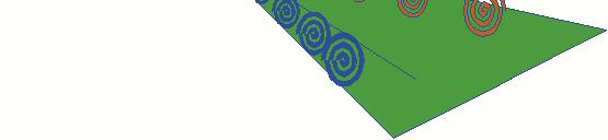


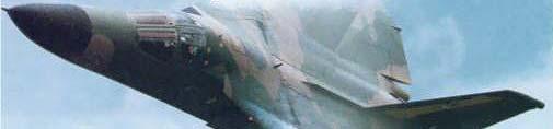
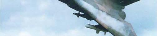
18 Vortex-Induced Lift and Delta Wings
19 Speed for Minimum Drag Total drag is composed of a part which depends on lift, and one that does not. Let us consider what it takes to keep L = W So. i.e, Or, Minimum Total Drag = twice zero lift drag.. This is a remarkable result: It means that: AIRCRAFT, UNLIKE OTHER FORMS OF TRANSPORTATION, HAVE A DEFINITE SPEED FOR MINIMUM DRAG!
20 To fly an airplane of a given weight, straight and level, the condition for minimum drag (maximum lift-to-drag ratio) is that the profile drag coefficient is the same as the induced drag coefficient.
21 Example An aircraft has a wing loading (W/S) of 130 pounds per square foot (6233N/m2), aspect ratio of 7.667, and wing span of 60.96m. We'll assume that its spanwise efficiency factor will be Let's assume that the profile drag coefficient is given by Thus, for maximum Lift-to-Drag ratio (minimum drag, and the lift is always equal to the weight for straight and level flight), The corresponding C L is calculated as 0.598, and the dynamic pressure is 10423N/m 2. At 11,000 meters in the Standard Atmosphere, density is 0.36kg/m 3, so that the flight speed is m/s. Note: In practice, the CD 0 might change with flight Mach number, for high-speed flight. This is not taken into account in the above.
22 AERODYNAMICS SUMMARY Lift is force perpendicular to the flow direction, due to pressure differences across surfaces. 3 ways of generating lift: a) angle of attack b) camber c) vortex-induced lift. An infinite (2-dimensional) wing is entirely described by its airfoil section. Finite wings have less lift than corresponding span-lengths of an infinite wing at the same angle of attack, and also have lift-induced drag. The total drag is composed of profile drag, which does not vary with lift, and induced drag, which rises as the square of the lift coefficient. To fly an airplane of a given weight, straight and level, the condition for minimum drag (maximum lift-to-drag ratio) is that the profile drag coefficient i is the same as the induced d drag coefficient.
23 WING LOADING AND CRUISE DESIGN POINT The wing loading,, is a decision i to be made by the designer. If W/S is low, then the aircraft will be efficient in low-speed flight, and perhaps have lower aerodynamic noise in high h speed flight, but the structure t may weigh too much (large wings) and the skin friction drag will be high in high-speed flight. Also, the aircraft will be more responsive to gusts, and hence will get bounced around a lot. Low wing loading is good for gliders and for aircraft intended for long endurance. The wing loading goes up as the expected design speed goes up. For a transonic airliner, a typical wing loading value is around 120 to 140 psf.

24 Design Step Select cruise wing loading find wing area 11. Select wing span find aspect ratio 12. Find cruise lift coefficient 13. Guess achievable zero-lift drag coefficient. Find induced drag coefft;, total L/D 14. Find speed for minimum drag
ROAD MAP... D-1: Aerodynamics of 3-D Wings D-2: Boundary Layer and Viscous Effects D-3: XFLR (Aerodynamics Analysis Tool)
") Unit D-1: Aerodynamics of 3-D Wings Page 1 of 5 AE301 Aerodynamics I UNIT D: Applied Aerodynamics ROAD MAP... D-1: Aerodynamics of 3-D Wings D-: Boundary Layer and Viscous Effects D-3: XFLR (Aerodynamics
Unit D-1: Aerodynamics of 3-D Wings Page 1 of 5 AE301 Aerodynamics I UNIT D: Applied Aerodynamics ROAD MAP... D-1: Aerodynamics of 3-D Wings D-: Boundary Layer and Viscous Effects D-3: XFLR (Aerodynamics
The effect of back spin on a table tennis ball moving in a viscous fluid.
 How can planes fly? The phenomenon of lift can be produced in an ideal (non-viscous) fluid by the addition of a free vortex (circulation) around a cylinder in a rectilinear flow stream. This is known as
Lift for a Finite Wing. all real wings are finite in span (airfoils are considered as infinite in the span)
") Lift for a Finite Wing all real wings are finite in span (airfoils are considered as infinite in the span) The lift coefficient differs from that of an airfoil because there are strong vortices produced
Lift for a Finite Wing all real wings are finite in span (airfoils are considered as infinite in the span) The lift coefficient differs from that of an airfoil because there are strong vortices produced
C-1: Aerodynamics of Airfoils 1 C-2: Aerodynamics of Airfoils 2 C-3: Panel Methods C-4: Thin Airfoil Theory
 ROAD MAP... AE301 Aerodynamics I UNIT C: 2-D Airfoils C-1: Aerodynamics of Airfoils 1 C-2: Aerodynamics of Airfoils 2 C-3: Panel Methods C-4: Thin Airfoil Theory AE301 Aerodynamics I : List of Subjects
AE Dept., KFUPM. Dr. Abdullah M. Al-Garni. Fuel Economy. Emissions Maximum Speed Acceleration Directional Stability Stability.
 Aerodynamics: Introduction Aerodynamics deals with the motion of objects in air. These objects can be airplanes, missiles or road vehicles. The Table below summarizes the aspects of vehicle performance
The subsonic compressibility effect is added by replacing. with
 Swept Wings The main function of a swept wing is to reduce wave drag at transonic and supersonic speeds. Consider a straight wing and a swept wing in a flow with a free-stream velocity V. Assume that the
Basic Fluid Mechanics
 Basic Fluid Mechanics Chapter 7B: Forces on Submerged Bodies 7/26/2018 C7B: Forces on Submerged Bodies 1 Forces on Submerged Bodies Lift and Drag are forces exerted on an immersed body by the surrounding
Jet Propulsion. Lecture-17. Ujjwal K Saha, Ph. D. Department of Mechanical Engineering Indian Institute of Technology Guwahati
 Lecture-17 Prepared under QIP-CD Cell Project Jet Propulsion Ujjwal K Saha, Ph. D. Department of Mechanical Engineering Indian Institute of Technology Guwahati 1 Lift: is used to support the weight of
Wing-Body Combinations
 Wing-Body Combinations even a pencil at an angle of attack will generate lift, albeit small. Hence, lift is produced by the fuselage of an airplane as well as the wing. The mating of a wing with a fuselage
Preliminary design of a high-altitude kite. A flexible membrane kite section at various wind speeds
 Preliminary design of a high-altitude kite A flexible membrane kite section at various wind speeds This is the third paper in a series that began with one titled A flexible membrane kite section at high
It should be noted that the symmetrical airfoil at zero lift has no pitching moment about the aerodynamic center because the upper and
 NAVWEPS -81-8 and high power, the dynamic pressure in the shaded area can be much greater than the free stream and this causes considerably greater lift than at zero thrust. At high power conditions the
Aerodynamic Terms. Angle of attack is the angle between the relative wind and the wing chord line. [Figure 2-2] Leading edge. Upper camber.
![Aerodynamic Terms. Angle of attack is the angle between the relative wind and the wing chord line. [Figure 2-2] Leading edge. Upper camber.](/thumbs/82/86661300.jpg "Aerodynamic Terms. Angle of attack is the angle between the relative wind and the wing chord line. [Figure 2-2] Leading edge. Upper camber.") Chapters 2 and 3 of the Pilot s Handbook of Aeronautical Knowledge (FAA-H-8083-25) apply to powered parachutes and are a prerequisite to reading this book. This chapter will focus on the aerodynamic fundamentals
Chapters 2 and 3 of the Pilot s Handbook of Aeronautical Knowledge (FAA-H-8083-25) apply to powered parachutes and are a prerequisite to reading this book. This chapter will focus on the aerodynamic fundamentals
No Description Direction Source 1. Thrust
 AERODYNAMICS FORCES 1. WORKING TOGETHER Actually Lift Force is not the only force working on the aircraft, during aircraft moving through the air. There are several aerodynamics forces working together
Aerodynamic Analysis of a Symmetric Aerofoil
 214 IJEDR Volume 2, Issue 4 ISSN: 2321-9939 Aerodynamic Analysis of a Symmetric Aerofoil Narayan U Rathod Department of Mechanical Engineering, BMS college of Engineering, Bangalore, India Abstract - The
PRE-TEST Module 2 The Principles of Flight Units /60 points
 PRE-TEST Module 2 The Principles of Flight Units 1-2-3.../60 points 1 Answer the following questions. (20 p.) moving the plane (4) upward / forward. Opposed to that is 1. What are the names of the four
J. Szantyr Lecture No. 21 Aerodynamics of the lifting foils Lifting foils are important parts of many products of contemporary technology.
 J. Szantyr Lecture No. 21 Aerodynamics of the lifting foils Lifting foils are important parts of many products of contemporary technology. < Helicopters Aircraft Gliders Sails > < Keels and rudders Hydrofoils
Four forces on an airplane
 Four forces on an airplane By NASA.gov on 10.12.16 Word Count 824 Level MAX TOP: An airplane pictured on June 30, 2016. Courtesy of Pexels. BOTTOM: Four forces on an airplane. Courtesy of NASA. A force
BUILD AND TEST A WIND TUNNEL
 LAUNCHING INTO AVIATION 9 2018 Aircraft Owners and Pilots Association. All Rights Reserved. UNIT 2 SECTION D LESSON 2 PRESENTATION BUILD AND TEST A WIND TUNNEL LEARNING OBJECTIVES By the end of this lesson,
ME 239: Rocket Propulsion. Forces Acting on a Vehicle in an Atmosphere (Follows Section 4.2) J. M. Meyers, PhD
 J. M. Meyers, PhD") ME 239: Rocket Propulsion Forces Acting on a Vehicle in an Atmosphere (Follows Section 4.2) J. M. Meyers, PhD 1 Commonly acting forces on a vehicle flying in a planetary atmosphere: Thrust Aerodynamic
ME 239: Rocket Propulsion Forces Acting on a Vehicle in an Atmosphere (Follows Section 4.2) J. M. Meyers, PhD 1 Commonly acting forces on a vehicle flying in a planetary atmosphere: Thrust Aerodynamic
Principles of glider flight
 Principles of glider flight [ Lecture 1: Lift, drag & glide performance ] Richard Lancaster Email: Richard@RJPLancaster.net Twitter: @RJPLancaster ASK-21 illustrations Copyright 1983 Alexander Schleicher
Investigation on 3-D Wing of commercial Aeroplane with Aerofoil NACA 2415 Using CFD Fluent
 Investigation on 3-D of commercial Aeroplane with Aerofoil NACA 2415 Using CFD Fluent Rohit Jain 1, Mr. Sandeep Jain 2, Mr. Lokesh Bajpai 3 1PG Student, 2 Associate Professor, 3 Professor & Head 1 2 3
Aircraft Design: A Systems Engineering Approach, M. Sadraey, Wiley, Figures
 Aircraft Design: A Systems Engineering Approach, M. Sadraey, Wiley, 2012 Chapter 5 Wing Design Figures 1 Identify and prioritize wing design requirements (Performance, stability, producibility, operational
DEFINITIONS. Aerofoil
 Aerofoil DEFINITIONS An aerofoil is a device designed to produce more lift (or thrust) than drag when air flows over it. Angle of Attack This is the angle between the chord line of the aerofoil and the
CFD ANALYSIS OF FLOW AROUND AEROFOIL FOR DIFFERENT ANGLE OF ATTACKS
 www.mechieprojects.com CFD ANALYSIS OF FLOW AROUND AEROFOIL FOR DIFFERENT ANGLE OF ATTACKS PRESENTATION OUTLINE AIM INTRODUCTION LITERATURE SURVEY CFD ANALYSIS OF AEROFOIL RESULTS CONCLUSIONS www.mechieprojects.com
AERODYNAMIC CHARACTERISTICS OF NACA 0012 AIRFOIL SECTION AT DIFFERENT ANGLES OF ATTACK
 AERODYNAMIC CHARACTERISTICS OF NACA 0012 AIRFOIL SECTION AT DIFFERENT ANGLES OF ATTACK SUPREETH NARASIMHAMURTHY GRADUATE STUDENT 1327291 Table of Contents 1) Introduction...1 2) Methodology.3 3) Results...5
Detailed study 3.4 Topic Test Investigations: Flight
 Name: Billanook College Detailed study 3.4 Topic Test Investigations: Flight Ivanhoe Girls Grammar School Questions 1 and 2 relate to the information shown in the diagram in Figure 1. z Question 1 y Figure
STUDIES ON THE OPTIMUM PERFORMANCE OF TAPERED VORTEX FLAPS
 ICAS 2000 CONGRESS STUDIES ON THE OPTIMUM PERFORMANCE OF TAPERED VORTEX FLAPS Kenichi RINOIE Department of Aeronautics and Astronautics, University of Tokyo, Tokyo, 113-8656, JAPAN Keywords: vortex flap,
Drag Divergence and Wave Shock. A Path to Supersonic Flight Barriers
 Drag Divergence and Wave Shock A Path to Supersonic Flight Barriers Mach Effects on Coefficient of Drag The Critical Mach Number is the velocity on the airfoil at which sonic flow is first acquired If
Aero Club. Introduction to Flight
 Aero Club Presents Introduction to RC Modeling Module 1 Introduction to Flight Centre For Innovation IIT Madras Page2 Table of Contents Introduction:... 3 How planes fly How is lift generated?... 3 Forces
Reduction of Skin Friction Drag in Wings by Employing Riblets
 Reduction of Skin Friction Drag in Wings by Employing Riblets Kousik Kumaar. R 1 Assistant Professor Department of Aeronautical Engineering Nehru Institute of Engineering and Technology Coimbatore, India
Theory of Flight Aircraft Design and Construction. References: FTGU pages 9-14, 27
 Theory of Flight 6.01 Aircraft Design and Construction References: FTGU pages 9-14, 27 Main Teaching Points Parts of an Airplane Aircraft Construction Landing Gear Standard Terminology Definition The airplane
EXPERIMENTAL ANALYSIS OF FLOW OVER SYMMETRICAL AEROFOIL Mayank Pawar 1, Zankhan Sonara 2 1,2
 EXPERIMENTAL ANALYSIS OF FLOW OVER SYMMETRICAL AEROFOIL Mayank Pawar 1, Zankhan Sonara 2 1,2 Assistant Professor,Chandubhai S. Patel Institute of Technology, CHARUSAT, Changa, Gujarat, India Abstract The
External Tank- Drag Reduction Methods and Flow Analysis
 External Tank- Drag Reduction Methods and Flow Analysis Shaik Mohammed Anis M.Tech Student, MLR Institute of Technology, Hyderabad, India. G. Parthasarathy Associate Professor, MLR Institute of Technology,
WHAT IS GLIDER? A light engineless aircraft designed to glide after being towed aloft or launched from a catapult.
 GLIDER BASICS WHAT IS GLIDER? A light engineless aircraft designed to glide after being towed aloft or launched from a catapult. 2 PARTS OF GLIDER A glider can be divided into three main parts: a)fuselage
Incompressible Flow over Airfoils
 Road map for Chap. 4 Incompressible Flow over Airfoils Aerodynamics 2015 fall - 1 - < 4.1 Introduction > Incompressible Flow over Airfoils Incompressible flow over airfoils Prandtl (20C 초 ) Airfoil (2D)
CASE STUDY FOR USE WITH SECTION B
 GCE A level 135/01-B PHYSICS ASSESSMENT UNIT PH5 A.M. THURSDAY, 0 June 013 CASE STUDY FOR USE WITH SECTION B Examination copy To be given out at the start of the examination. The pre-release copy must
Experimental and Theoretical Investigation for the Improvement of the Aerodynamic Characteristic of NACA 0012 airfoil
 International Journal of Mining, Metallurgy & Mechanical Engineering (IJMMME) Volume 2, Issue 1 (214) ISSN 232 46 (Online) Experimental and Theoretical Investigation for the Improvement of the Aerodynamic
Aerodynamics Principles
 Aerodynamics Principles Stage 1 Ground Lesson 3 Chapter 3 / Pages 2-18 3:00 Hrs Harold E. Calderon AGI, CFI, CFII, and MEI Lesson Objectives Become familiar with the four forces of flight, aerodynamic
Effect of Co-Flow Jet over an Airfoil: Numerical Approach
 Contemporary Engineering Sciences, Vol. 7, 2014, no. 17, 845-851 HIKARI Ltd, www.m-hikari.com http://dx.doi.org/10.12988/ces.2014.4655 Effect of Co-Flow Jet over an Airfoil: Numerical Approach Md. Riajun
Chapter 5 Wing design - selection of wing parameters - 4 Lecture 22 Topics
 Chapter 5 Wing design - selection of wing parameters - Lecture Topics 5.3.9 Ailerons 5.3.0 Other aspects of wing design Example 5. 5.3.9 Ailerons The main purpose of the ailerons is to create rolling moment
Aircraft Stability and Performance 2nd Year, Aerospace Engineering. Dr. M. Turner
 Aircraft Stability and Performance 2nd Year, Aerospace Engineering Dr. M. Turner Basic Info Timetable 15.00-16.00 Monday Physics LTA 16.00-17.00 Monday Physics LTA Exam 2 1 2 hour exam 6 questions 2 from
The Fly Higher Tutorial IV
 The Fly Higher Tutorial IV THE SCIENCE OF FLIGHT In order for an aircraft to fly we must have two things: 1) Thrust 2) Lift Aerodynamics The Basics Representation of the balance of forces These act against
Induced Drag Reduction for Modern Aircraft without Increasing the Span of the Wing by Using Winglet
 International Journal of Mechanical & Mechatronics Engineering IJMME-IJENS Vol:10 No:03 49 Induced Drag Reduction for Modern Aircraft without Increasing the Span of the Wing by Using Winglet Mohammad Ilias
Reynolds Number Effects on Leading Edge Vortices
 Reynolds Number Effects on Leading Edge Vortices Taken From AIAA-2002-2839 Paper Reynolds Numbers Considerations for Supersonic Flight Brenda M. Kulfan 32nd AIAA Fluid Dynamics Conference and Exhibit St.
Flow Over Bodies: Drag and Lift
 Fluid Mechanics (0905241) Flow Over Bodies: Drag and Lift Dr.-Eng. Zayed dal-hamamre 1 Content Overview Drag and Lift Flow Past Objects Boundary Layers Laminar Boundary Layers Transitional and Turbulent
Preliminary Design Review (PDR) Aerodynamics #2 AAE-451 Aircraft Design
 Aerodynamics #2 AAE-451 Aircraft Design") Preliminary Design Review (PDR) Aerodynamics #2 AAE-451 Aircraft Design Aircraft Geometry (highlight any significant revisions since Aerodynamics PDR #1) Airfoil section for wing, vertical and horizontal
Preliminary Design Review (PDR) Aerodynamics #2 AAE-451 Aircraft Design Aircraft Geometry (highlight any significant revisions since Aerodynamics PDR #1) Airfoil section for wing, vertical and horizontal
Design and Development of Micro Aerial Vehicle
 Advances in Aerospace Science and Applications. ISSN 2277-3223 Volume 4, Number 1 (2014), pp. 91-98 Research India Publications http://www.ripublication.com/aasa.htm Design and Development of Micro Aerial
CFD Analysis ofwind Turbine Airfoil at Various Angles of Attack
 IOSR Journal of Mechanical and Civil Engineering (IOSR-JMCE) e-issn: 2278-1684,p-ISSN: 2320-334X, Volume 13, Issue 4 Ver. II (Jul. - Aug. 2016), PP 18-24 www.iosrjournals.org CFD Analysis ofwind Turbine
Applied Fluid Mechanics
 Applied Fluid Mechanics 1. The Nature of Fluid and the Study of Fluid Mechanics 2. Viscosity of Fluid 3. Pressure Measurement 4. Forces Due to Static Fluid 5. Buoyancy and Stability 6. Flow of Fluid and
Chapter 5 Wing design - selection of wing parameters - 3 Lecture 21 Topics
 Chapter 5 Wing design - selection of wing parameters - 3 Lecture 21 Topics 5.3.2 Choice of sweep ( ) 5.3.3 Choice of taper ratio ( λ ) 5.3.4 Choice of twist ( ε ) 5.3.5 Wing incidence(i w ) 5.3.6 Choice
Measurement of Pressure. The aerofoil shape used in wing is to. Distribution and Lift for an Aerofoil. generate lift due to the difference
 Measurement of Pressure Distribution and Lift for an Aerofoil. Objective The objective of this experiment is to investigate the pressure distribution around the surface of aerofoil NACA 4415 and to determine
Aerodynamics of Winglet: A Computational Fluid Dynamics Study Using Fluent
 Aerodynamics of : A Computational Fluid Dynamics Study Using Fluent Rohit Jain 1, Mr. Sandeep Jain, Mr. Lokesh Bajpai 1PG Student, Associate Professor, Professor & Head 1 Mechanical Engineering Department
In parallel with steady gains in battery energy and power density, the coming generation of uninhabited aerial vehicles (UAVs) will enjoy increased
 will enjoy increased") In parallel with steady gains in battery energy and power density, the coming generation of uninhabited aerial vehicles (UAVs) will enjoy increased range, endurance, and operational capability by exploiting
In parallel with steady gains in battery energy and power density, the coming generation of uninhabited aerial vehicles (UAVs) will enjoy increased range, endurance, and operational capability by exploiting
A103 AERODYNAMIC PRINCIPLES
 A103 AERODYNAMIC PRINCIPLES References: FAA-H-8083-25A, Pilot s Handbook of Aeronautical Knowledge, Chapter 3 (pgs 4-10) and Chapter 4 (pgs 1-39) OBJECTIVE: Students will understand the fundamental aerodynamic
ANALYSIS OF AERODYNAMIC CHARACTERISTICS OF A SUPERCRITICAL AIRFOIL FOR LOW SPEED AIRCRAFT
 ANALYSIS OF AERODYNAMIC CHARACTERISTICS OF A SUPERCRITICAL AIRFOIL FOR LOW SPEED AIRCRAFT P.Sethunathan 1, M.Niventhran 2, V.Siva 2, R.Sadhan Kumar 2 1 Asst.Professor, Department of Aeronautical Engineering,
AE2610 Introduction to Experimental Methods in Aerospace AERODYNAMIC FORCES ON A WING IN A SUBSONIC WIND TUNNEL
 AE2610 Introduction to Experimental Methods in Aerospace AERODYNAMIC FORCES ON A WING IN A SUBSONIC WIND TUNNEL Objectives The primary objective of this experiment is to familiarize the student with measurement
Study on the Shock Formation over Transonic Aerofoil
 Advances in Aerospace Science and Applications. ISSN 2277-3223 Volume 3, Number 2 (2013), pp. 113-118 Research India Publications http://www.ripublication.com/aasa.htm Study on the Shock Formation over
Aerodynamics. A study guide on aerodynamics for the Piper Archer
 Aerodynamics A study guide on aerodynamics for the Piper Archer Aerodynamics The purpose of this pilot briefing is to discuss the simple and complex aerodynamics of the Piper Archer. Please use the following
PRINCIPLES OF FLIGHT
 CHAPTER 3 PRINCIPLES OF FLIGHT INTRODUCTION Man has always wanted to fly. Legends from the very earliest times bear witness to this wish. Perhaps the most famous of these legends is the Greek myth about
THEORY OF WINGS AND WIND TUNNEL TESTING OF A NACA 2415 AIRFOIL. By Mehrdad Ghods
 THEORY OF WINGS AND WIND TUNNEL TESTING OF A NACA 2415 AIRFOIL By Mehrdad Ghods Technical Communication for Engineers The University of British Columbia July 23, 2001 ABSTRACT Theory of Wings and Wind
CFD Study of Solid Wind Tunnel Wall Effects on Wing Characteristics
 Indian Journal of Science and Technology, Vol 9(45), DOI :10.17485/ijst/2016/v9i45/104585, December 2016 ISSN (Print) : 0974-6846 ISSN (Online) : 0974-5645 CFD Study of Solid Wind Tunnel Wall Effects on
Aerofoil Profile Analysis and Design Optimisation
 Journal of Aerospace Engineering and Technology Volume 3, Issue 2, ISSN: 2231-038X Aerofoil Profile Analysis and Design Optimisation Kondapalli Siva Prasad*, Vommi Krishna, B.B. Ashok Kumar Department
CFD Analysis of Supercritical Airfoil with Different Camber
 CFD Analysis of Supercritical Airfoil with Different Camber S.Manikandan 1, R.G.Bhuvana 2, Sowmya.A.Srinivasan 3 Assistant prof, Department of Aeronautical Engineering, Jeppiaar Engineering College, Chennai,
Exploration Series. AIRPLANE Interactive Physics Simulation Page 01
 AIRPLANE ------- Interactive Physics Simulation ------- Page 01 What makes an airplane "stall"? An airplane changes its state of motion thanks to an imbalance in the four main forces acting on it: lift,
OBJECTIVE METHODOLOGY
 SKMA394 Measurement of Pressure Distribution around an Airfoil NACA445 OBJECTIVE The objective of this experiment is to study about the pressure distribution around the surface of aerofoil NACA 445 starting
Improved Aerodynamic Characteristics of Aerofoil Shaped Fuselage than that of the Conventional Cylindrical Shaped Fuselage
 International Journal of Scientific & Engineering Research Volume 4, Issue 1, January-213 1 Improved Aerodynamic Characteristics of Aerofoil Shaped Fuselage than that of the Conventional Cylindrical Shaped
A Performanced Based Angle of Attack Display
 A Performanced Based Angle of Attack Display David F. Rogers, Phd, ATP www.nar-associates.com The Problem The current angle of attack displays basically warn you about the approach to stall with yellow
Dillon Thorse Flow Visualization MCEN 4047 Team Poject 1 March 14th, 2013
 Dillon Thorse Flow Visualization MCEN 4047 Team Poject 1 March 14 th, 2013 1 Introduction I have always been entranced by flight. Recently I have been taking flying lessons, and I have been learning the
LESSONS 1, 2, and 3 PRACTICE EXERCISES
 LESSONS 1, 2, and 3 PRACTICE EXERCISES The following items will test your grasp of the material covered in these lessons. There is only one correct answer for each item. When you complete the exercise,
Aerodynamic investigations on a wing in ground effect
 Aerodynamic investigations on a wing in ground effect A summary of NLR activities in the Seabus-Hydaer programme W.B. de Wolf Nationaal Lucht- en Ruimtevaartlaboratorium National Aerospace Laboratory NLR
Uncontrolled copy not subject to amendment. Principles of Flight
 Uncontrolled copy not subject to amendment Principles of Flight Principles of Flight Learning Outcome 1: Know the principles of lift, weight, thrust and drag and how a balance of forces affects an aeroplane
Homework Exercise to prepare for Class #2.
 Homework Exercise to prepare for Class #2. Answer these on notebook paper then correct or improve your answers (using another color) by referring to the answer sheet. 1. Identify the major components depicted
A Different Approach to Teaching Engine-Out Glides
 A ifferent Approach to Teaching Engine-Out Glides es Glatt, Ph., ATP/CFI-AI, AGI/IGI When student pilots begin to learn about emergency procedures, the concept of the engine-out glide is introduced. The
Conceptual Design and Passive Stability of Tethered Platforms
 Conceptual Design and Passive Stability of Tethered Platforms Sara Smoot Advised by Ilan Kroo 1 Towed Bodies Definition: Two or more tethered objects immersed in a moving fluid. Aerostats Underwater towed
Computational Analysis of Cavity Effect over Aircraft Wing
 World Engineering & Applied Sciences Journal 8 (): 104-110, 017 ISSN 079-04 IDOSI Publications, 017 DOI: 10.589/idosi.weasj.017.104.110 Computational Analysis of Cavity Effect over Aircraft Wing 1 P. Booma
BRONZE LECTURES. Slides on bayriver.co.uk/gliding
 BRONZE LECTURES 2014 Slides on bayriver.co.uk/gliding 1 STUDY Lectures only meant to be a stimulus and provide an opportunity for questions EXAM paper is multi-choice with x sections. 2 READING BOOKS?
Aerodynamic Basics Larry Bogan - Jan 2002 version MECHANICS
 Aerodynamic Basics Larry Bogan - Jan 2002 version MECHANICS Vectors Force, displacement, acceleration, and velocity Inertia and Velocity Inertia is a property of mass. (When there is no force on an object,
EFFECT OF GURNEY FLAPS AND WINGLETS ON THE PERFORMANCE OF THE HAWT
 Chapter-6 EFFECT OF GURNEY FLAPS AND WINGLETS ON THE PERFORMANCE OF THE HAWT 6.1 Introduction The gurney flap (wicker bill) was a small flat tab projecting from the trailing edge of a wing. Typically it
Experimental Investigation of the Aerodynamics of a Modeled Dragonfly Wing Section
 Region I-MA Student Conference AIAA - 2005 April 8-9, 2005 / Charlottesville, Virginia Experimental Investigation of the Aerodynamics of a Modeled Dragonfly Wing Section Michelle Kwok * and Rajat Mittal
AERODYNAMICS I LECTURE 7 SELECTED TOPICS IN THE LOW-SPEED AERODYNAMICS
 LECTURE 7 SELECTED TOPICS IN THE LOW-SPEED AERODYNAMICS The sources of a graphical material used in this lecture are: [UA] D. McLean, Understanding Aerodynamics. Arguing from the Real Physics. Wiley, 2013.
What happens to a fluid (water or air) when it moves from entering a wide opening to entering a narrow opening?
 when it moves from entering a wide opening to entering a narrow opening?") What happens to a fluid (water or air) when it moves from entering a wide opening to entering a narrow opening? The water (or air) speeds up. Since the same amount of water/air has to travel through a
What happens to a fluid (water or air) when it moves from entering a wide opening to entering a narrow opening? The water (or air) speeds up. Since the same amount of water/air has to travel through a
Parasite Drag. by David F. Rogers Copyright c 2005 David F. Rogers. All rights reserved.
 Parasite Drag by David F. Rogers http://www.nar-associates.com Copyright c 2005 David F. Rogers. All rights reserved. How many of you still have a Grimes rotating beacon on both the top and bottom of the
Aircraft Stability and Control Prof. A. K. Ghosh Department of Aerospace Engineering Indian Institute of Technology-Kanpur. Lecture- 25 Revision
 Aircraft Stability and Control Prof. A. K. Ghosh Department of Aerospace Engineering Indian Institute of Technology-Kanpur Lecture- 25 Revision Yes, dear friends, this is the mann ki baat session for lateral
ROTORS for WIND POWER
 ROTORS for WIND POWER P.T. Smulders Wind Energy Group Faculty of Physics University of Technology, Eindhoven ARRAKIS 1 st edition October 1991 revised edition January 2004 CONTENTS ROTORS for WIND POWER...
5th Symposium on Integrating CFD and Experiments in Aerodynamics (Integration 2012) th Symposium on Integrating CFD and Experiments in Aerodynam
 th Symposium on Integrating CFD and Experiments in Aerodynam") 5th Symposium on Integrating CFD and Experiments in Aerodynamics (Integration 202) 36 Multi-objective Optimization of Airfoil of Mars Exploration Aircraft using Evolutionary Algorithm Gaku Sasaki Tomoaki
5th Symposium on Integrating CFD and Experiments in Aerodynamics (Integration 202) 36 Multi-objective Optimization of Airfoil of Mars Exploration Aircraft using Evolutionary Algorithm Gaku Sasaki Tomoaki
Aerodynamic Analysis of Blended Winglet for Low Speed Aircraft
 , July 1-3, 2015, London, U.K. Aerodynamic Analysis of Blended Winglet for Low Speed Aircraft Pooja Pragati, Sudarsan Baskar Abstract This paper provides a practical design of a new concept of massive
Understanding Flight: Newton Reigns in Aerodynamics! General Aviation. Scott Eberhardt March 26, What you will learn today. Descriptions of Lift
 Understanding Flight: Newton Reigns in Aerodynamics! General Aviation Scott Eberhardt March 26, 2007 Military Aviation Commercial Aviation What you will learn today Some of the things you learned might
EXPERIMENTAL ANALYSIS OF THE CONFLUENT BOUNDARY LAYER BETWEEN A FLAP AND A MAIN ELEMENT WITH SAW-TOOTHED TRAILING EDGE
 24 TH INTERNATIONAL CONGRESS OF THE AERONAUTICAL SCIENCES EXPERIMENTAL ANALYSIS OF THE CONFLUENT BOUNDARY LAYER BETWEEN A FLAP AND A MAIN ELEMENT WITH SAW-TOOTHED TRAILING EDGE Lemes, Rodrigo Cristian,
This IS A DRAG IS IT A LIFT!!!!! Aerodynamics
 Problems in Technology This IS A DRAG OR IS IT A LIFT!!!!! Aerodynamics Our mission is to better understand the science and study of aerodynamics. Well, simply put aerodynamics is the way air moves around
A COMPUTATIONAL STUDY ON THE DESIGN OF AIRFOILS FOR A FIXED WING MAV AND THE AERODYNAMIC CHARACTERISTIC OF THE VEHICLE
 28 TH INTERNATIONAL CONGRESS OF THE AERONAUTICAL SCIENCES A COMPUTATIONAL STUDY ON THE DESIGN OF AIRFOILS FOR A FIXED WING MAV AND THE AERODYNAMIC CHARACTERISTIC OF THE VEHICLE Jung-Hyun Kim*, Kyu-Hong
Low Speed Wind Tunnel Wing Performance
 Low Speed Wind Tunnel Wing Performance ARO 101L Introduction to Aeronautics Section 01 Group 13 20 November 2015 Aerospace Engineering Department California Polytechnic University, Pomona Team Leader:
Offset of Shock Location in Supercritical Airfoils
 Offset of Shock Location in Supercritical Airfoils Sonia Chalia Assistant Professor, Department of Aerospace Engineering, Amity University Haryana, Haryana, India ---------------------------------------------------------------------***---------------------------------------------------------------------
INTERFERENCE EFFECT AND FLOW PATTERN OF FOUR BIPLANE CONFIGURATIONS USING NACA 0024 PROFILE
 Proceedings of the International Conference on Mechanical Engineering 211 (ICME211) 18-2 December 211, Dhaka, Bangladesh ICME11-FL-1 INTERFERENCE EFFECT AND FLOW PATTERN OF FOUR BIPLANE CONFIGURATIONS
SOARING AND GLIDING FLIGHT OF THE BLACK VULTURE
 [ 280 ] SOARING AND GLIDING FLIGHT OF THE BLACK VULTURE BY B. G. NEWMAN* Department of Engineering, University of Cambridge {Received 10 September 1957) INTRODUCTION In 1950 Raspet published an interesting
ScienceDirect. Investigation of the aerodynamic characteristics of an aerofoil shaped fuselage UAV model
 Available online at www.sciencedirect.com ScienceDirect Procedia Engineering 90 (2014 ) 225 231 10th International Conference on Mechanical Engineering, ICME 2013 Investigation of the aerodynamic characteristics
Big News! Dick Kline Inventor of the KF AirFoil Contacts rcfoamfighters.
 Big News! Dick Kline Inventor of the KF AirFoil Contacts rcfoamfighters. (Copy of Email from Dick Kline to rcfoamfighters on 3/28/09) --------------------------------------------------------------------------------
Aerodynamic Performance Enhancement of a NACA Airfoil Using Supersonic Channel Airfoil Design
 46th AIAA Aerospace Sciences Meeting and Exhibit AIAA 2008-300 7-10 January 2008, Reno, Nevada Aerodynamic Performance Enhancement of a NACA 66-206 Airfoil Using Supersonic Channel Airfoil Design David
Lecture # 08: Boundary Layer Flows and Controls
 AerE 344 Lecture Notes Lecture # 8: Boundary Layer Flows and Controls Dr. Hui Hu Department of Aerospace Engineering Iowa State University Ames, Iowa 511, U.S.A Flow Separation on an Airfoil Quantification
STUDY OF VARIOUS NACA SERIES AEROFOIL SECTIONS AND WING CONTOUR GENERATION USING CATIA V5
 STUDY OF VARIOUS NACA SERIES AEROFOIL SECTIONS AND WING CONTOUR GENERATION USING CATIA V5 Pawan Kumar Department of Aeronautical Engineering, Desh Bhagat University, Punjab, India ABSTRACT Aerofoil is
JAR-23 Normal, Utility, Aerobatic, and Commuter Category Aeroplanes \ Issued 11 March 1994 \ Section 1- Requirements \ Subpart C - Structure \ General
 JAR 23.301 Loads \ JAR 23.301 Loads (a) Strength requirements are specified in terms of limit loads (the maximum loads to be expected in service) and ultimate loads (limit loads multiplied by prescribed