- From 2005 year model, replacing with RM250 with 2-stroke engine, RM-Z450 with 4-stroke engine was introduced in the market. - From 2008 year model,
|
|
|
- Sharleen Barrett
- 5 years ago
- Views:
Transcription
1 1
 was introduced instead of conventional front")
2 - From 2005 year model, replacing with RM250 with 2-stroke engine, RM-Z450 with 4-stroke engine was introduced in the market. - From 2008 year model, fuel injection system was introduced instead of carburetor system - From 2013 year model, separate function front fork (SFF) was introduced instead of conventional front fork. - From 2015 year model, the front fork is updated as SFF-Air. 2

3 RM-Z450 got 1 world title, 6 AMA titles and 10 national titles from 2005 to 2013 year. 3
4 4
5 5

6 6

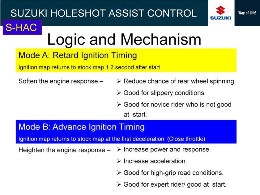
7 Mode-A assists hole shot with smoother engine response. It is suitable to novice riders and riders who is not good at start at race. In respect of the ground condition, it is effective to slippery ground condition. Mode-B assists hole shot with aggressive engine response. It is suitable to expert riders having good skill at start. In respect of the ground condition, it is effective to good-grip ground condition. 7

8 Champion riders involved in development of S-HAC. 8

9 When you use holeshot assist control, you need to press the switch to select either A or B-mode after engine start. To select A-mode, hold pressing the switch for one second. To select B-mode, hold pressing the switch for two seconds. After the mode selection, S-HAC mode is canceled if you press the switch again. The switch button lights on or flashing, and it indicates the selected mode condition. 9

10 Ignition timing is retarded in A-mode to stabilize the machine at the moment of start by increasing tire thrust force to the ground while reducing chance of the wheel spinning. The ignition map returns to the normal map when shifting up to 3rd gear position or 1.2 seconds after the start whichever comes first. 10

11 Ignition timing is advanced in B-mode producing strong power and response. The ignition map returns to the normal map when shifting up to 4th gear position, 4.5 seconds after the start or closing throttle, whichever comes first. 11

12 Tire traction force at start varies by throttle position and gear position. Therefore, ECM monitors throttle position and gear position to optimize the ignition timing at the short moment of start. Program of the ignition timing adjustment is different in the modes A and B. 12
13 13
14 14

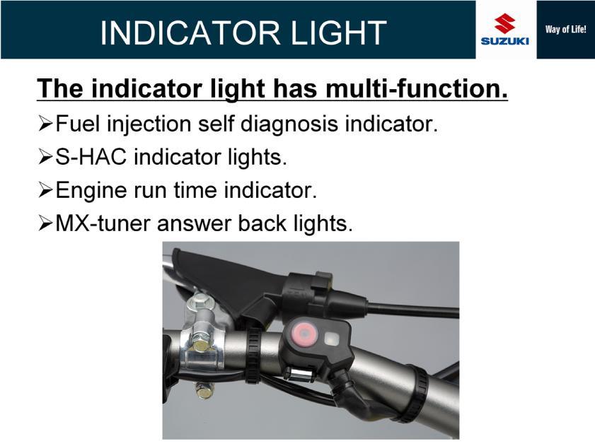
15 Due to the new system of S-HAC, multi-function indicator light is newly installed on 2015 year model. The indicator light functions not only for S-HAC but also for engine run time check and MX-tuner answer back. Up to 2014 year model, you need to have the option light device for engine run time check and MX-tuner answer back Now the option light device is no more necessary. 15
, and Indicator output means output to multi-function indicator light.")
16 Name of terminal No. 4 was changed from FI indicator to Indicator output. FI indicator means output to the option light device (FI indicator light), and Indicator output means output to multi-function indicator light. Terminal No. 29 was added for S-HAC switch. Other terminals are same as 2014 year model. 16

17 17
18 18

19 19

20 20
21 21
22 22
23 23
24 24

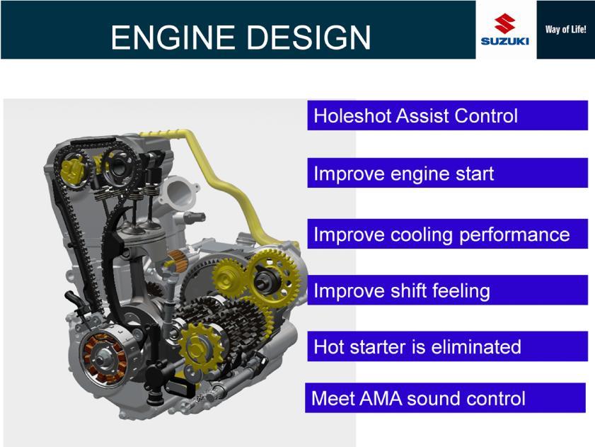
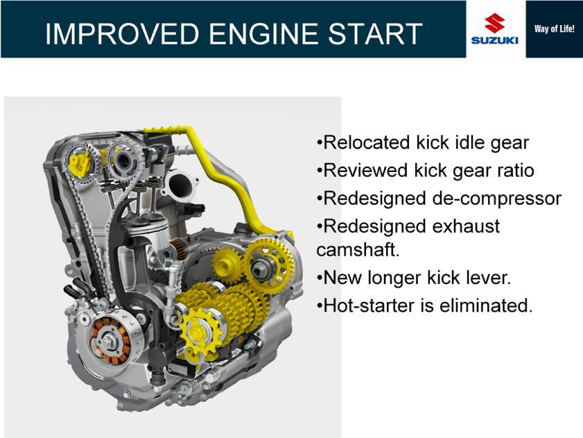
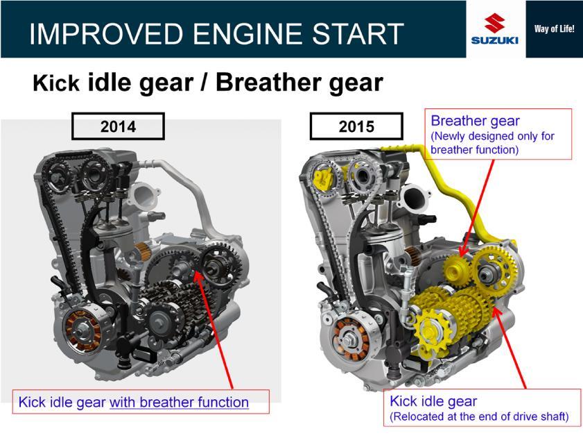
25 Up to 2014 year model, at the kick start operation, kick rotation force applied to the kick drive gear by kick lever is transferred to kick idle gear having breather function. 25

26 On 2015 year model, a new gear was newly located as a kick idle gear. The kick idle gear having breather function on 2014 year model remains located in the same location. However the gear has only the breather function and no more function of kick idle gear. 26

27 Decompression device design was totally changed. Operation angle of decompression lever was decreased and the decompression arm shape was changed to optimize the tappet-lift timing and amount. 27

28 New decompression device improved in secure operation to the exhaust tappet, resulting in ease engine start. 28
29 29

30 Straight water passage increased water flow by 16%. 30

31 Connection pipe shape was changed from T-shape to Y-shape to improve water flow from left radiator. 31

32 Precision of gear matching with the counter shaft and drive shaft was increased. 32
33 33
34 Torque at low range and rev-up character were improved. 34
35 35
36 36
37 37
38 38

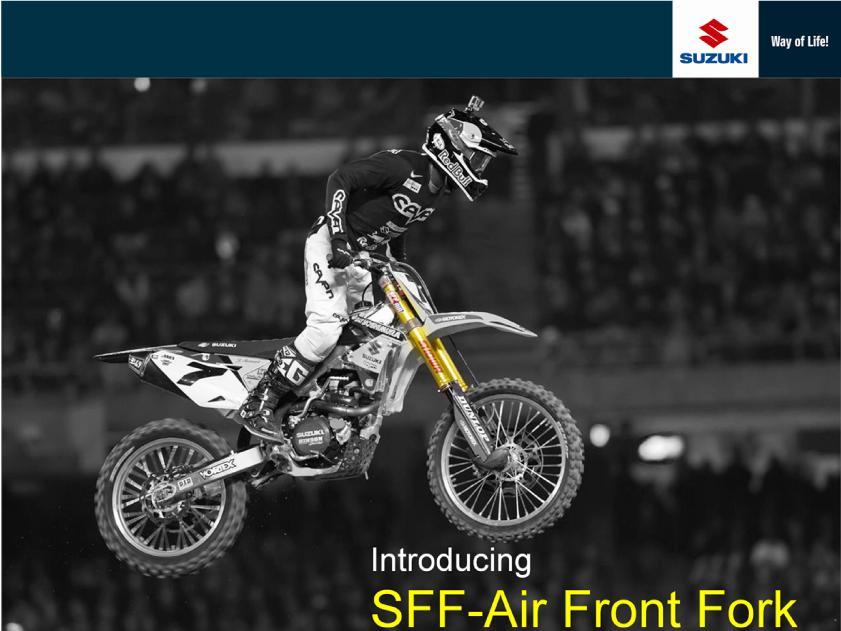
39 Spring fork unit at right side was changed to air spring unit. Eliminating the coil spring reduced the weight. 39

40 Same as 2014 year model, each right and left fork has separate function. Right fork is air spring unit and left fork is hydraulic damper unit. 40

41 Development of the air front fork was done with factory machines in the race activity. 41

42 While coil spring needs to be replaced to change spring rate on conventional fork, air fork only needs to adjust air pressure.. During race, time to change spring rate is much shortened, and customer does not need to purchase fork spring with different rate. Eliminating coil spring as the heaviest part of front fork achieved 1,100 g weight reduction. Air spring fork is free from heat of the separated hydraulic damper fork. This benefit is the same as the previous SFF. 42

43 Piston diameter increased by 1 mm improved to gain stabilized damping performance. Inner rod increased by 2.5 mm optimized the stiffness. 43

44 Under free condition of the air fork, increase of air volume in the inner air chamber acts to stretche the fork. This condition is the same in outer air chamber. However, that is opposite in balance air chamber. Increase of air volume in the balance air chamber acts to retract the fork. 44

45 Left picture shows SFF on 2014 year model, and right picture shows SFF-Air on 2015 year model. Coil spring (red part) is replaced with inner air chamber of air fork. Yellow space on both coil spring fork and air spring fork has the same function. According to inner tube retracted, air space of yellow part is compressed and it reacts as air spring. This means that the coil spring fork also has a sub air-spring function producing tension force together with the coil spring. As to balance air chamber (blue part), there is not the same spring function on the coil spring fork. 45
 while air volume of")
46 This is a simple drawing showing construction of the 3 chambers. When the fork is retracted, red and yellow air volumes decrease (pressure increase) while air volume of blue part increases (pressure decrease). 46

47 47
48 48

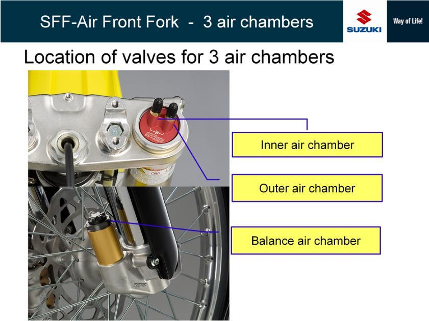
49 Two air valves for inner air chamber and outer air chamber are located on the top of fork body. Outer circle mark indicates the outer air chamber and inner dot mark indicates the inner air chamber. 49
50 50
 Balance air chamber This chamber is also pressurized to 1200 kpa (standard setting) and the air pressure acts to shorten the front fork.")
51 (1) Inner air chamber This chamber is pressurized to 1200 kpa (standard setting) and the air pressure acts to stretch the front fork, and it mainly determines the suspension force throughout the fork stroke. (2) Balance air chamber This chamber is also pressurized to 1200 kpa (standard setting) and the air pressure acts to shorten the front fork. (Opposed force against the air pressure of inner air chamber) According to increase of the fork stroke, the inner air pressure increases and the balance air pressure decreases. The balance air pressure is highest in the fork fully-stretched condition, and it determines the suspension force in the initial stroke range in combination with the inner air pressure. The total suspension force character throughout the fork stroke is determined by the combination force of produced by the inner air chamber and the balance air chamber. (3) Outer air chamber Outer air chamber is the internal space of fork outer tube surrounding the inner air chamber. This chamber is not pressurized (0 kpa) in the standard setting unlike the inner air chamber and the balance air chamber. Suspension setting can be changed 51
52 harder by the pressure adjustment of inner air chamber and balance air chamber within the specified range in the owner s service manual. However, after the setting adjustment to harder, if a customer needs further hard setting, outer air pressure can be increased to obtain further hard setting. 51

53 Piston diameter increased by 1 mm improved to gain stabilized damping performance. Inner rod increased by 2.5 mm optimized the stiffness balance of right and left forks. Inner tube diameter increased by 1 mm optimized the fork stiffness. 52

54 Air spring has a progressive character. 53

55 In the case of changing air pressure of both inner air chamber and outer air chamber, spring force change in the initial stroke is minimal and large in the end stroke by keeping the progressive character. 54
56 In the case of changing the inner air only, the spring force changes in overall stroke range. 55

57 In the case of increasing the balance air only, the spring force at the initial stroke becomes soft. In the case of decreasing the balance air only, the spring force at the initial stroke becomes hard. The point is that the balance air affects the setting in the initial stroke. 56
58 Imagine an injector. 57
59 Plug at the both ends for airtightness. 58

60 Now A and B are in atmospheric pressure condition. And then pressurize both up to 1200 kpa. This is the same as the standard pressure of inner air and balance air of SFF-Air fork. In this condition, the piston seems to be floating between A and B. 59
61 When the piston goes up, A volume decreases and pressure increases and B volume increases and pressure decreases. By the piston movement amount, A pressure increases accordingly and it produces a pushing force against the piston like a coil spring. 60

62 When the piston goes down, A volume increases and pressure decreases and B volume decreases and the pressure increases. 61

63 A is equivalent to the inner air chamber of the air fork. B is equivalent to the balance air chamber inner of the air fork. 62

64 The piston receives the both force from A and B. Inner air creates a force to push down the piston, and balance air creates a force to push up the piston. 63

65 Left drawing shows a injector with B air chamber. Right drawing shows a injector without B. Under free load condition to the piston, the piston is in a position that A and B pressures are in balance, and a minimal external force can start pushing up the piston. The relationship between the piston stroke and the reaction force (air spring force) is shown in the graphic drawings. If B does not exists, a certain force is required to start pushing up the piston. This condition on a front fork means an excessive hard setting of spring pre-load. 64

66 In this drawing, the injector is covered by a cylinder-shaped case producing another air chamber kept airtight.. This cylinder-shaped case is equivalent to the outer tube of front fork, and the yellow air chamber is equivalent to outer air chamber of SFF-Air fork. 65

67 1. Air pressure of air chambers of air fork must be checked before riding as well as tire. 2. Use a hand-operation pump to charge air. Never use a compressor because instant charge of high pressure may damage the inner parts of air fork. 3. Order of charging air to the 3 air chambers are specified. Air charge in different order will result in abnormal setting against the desired setting by SMC. 4. Each of 3 air chambers requires the specified amount of fork oil. Unlike a conventional front fork, you need to pour fork oil into three air chambers one by one. Oil in each chamber slightly leaks down to balance air chamber gradually by repeated fork stroke during race over time, and neglecting the fork oil replacement may cause oil level change in the air chambers. And the oil level change affects the air volume of the 3 air chambers. And the remarkable air volume change will result in the setting. Air spring character changes by air volume if adjusted the same pressure.. On a conventional front fork, addition of fork oil amount over the specified amount makes fork setting hard. This means that air pressure becomes high shortly according to the fork stroke due to the reduced inner air volume of front fork. Therefore, make sure to replace the front fork oil following the specified schedule 5. Oil may jet out from the valve when releasing air pressure. If the fork is lying on a desk, it allows the oil to move around the valve and enables oil jetting out when releasing air. To avoid the risk, place a rag around the valve when releasing air. 66

68 Air pressure of air chambers of air fork must be checked before riding as well as tire. 67

69 Use a hand-operation pump to charge air. Never use a compressor because instant charge of high pressure may damage the inner parts of air fork. 68

70 Air pump should be able to charge air up to 1500 kpa. Desirable pressure gauge scale is kpa. And 50 kpa scale step is desirable for precise setting adjustment. 69

71 Adjustable range of outer air chamber is kpa, and it is much lower than inner air chamber and balance air chamber. Desirable pressure gauge scale is kpa for outer air chamber. And 10 kpa scale step is desirable for precise setting adjustment. 70

72 Because adjustable pressure range of outer air chamber is much lower than the other air chambers, 2 air gauges with different scale should be prepared. Air gauge is attached to this sample of air pump and the air gauge is detachable. Two different scale gauges can be attach to the pump body. This can allow air charging and adjusting the air pressure with one air pump for all 3 air chambers in short time. 71

73 Valve attachment of this air pump sample is screw down type. This type is recommended for the air pump or air gauge using for the air fork. When charging or adjusting air pressure of tire, air pressure of tire is momently released from the tire valve at the moment that the air gauge attachment is removed from the tire valve after the tire air adjustment operation. This type of valve attachment prevents momentary air release such as above. Different from tire air adjustment, air pressure of air fork is much higher. Therefore, for precise setting adjustment to certain pressure value, air release at the end of pressure check job with an air gauge should be minimized. 72

74 This air pump sample has quick air release device. Pressing the button to release the air. It is convenient to adjust air pressure to the desired value shortly. It is recommended to use an air gauge having such device. 73

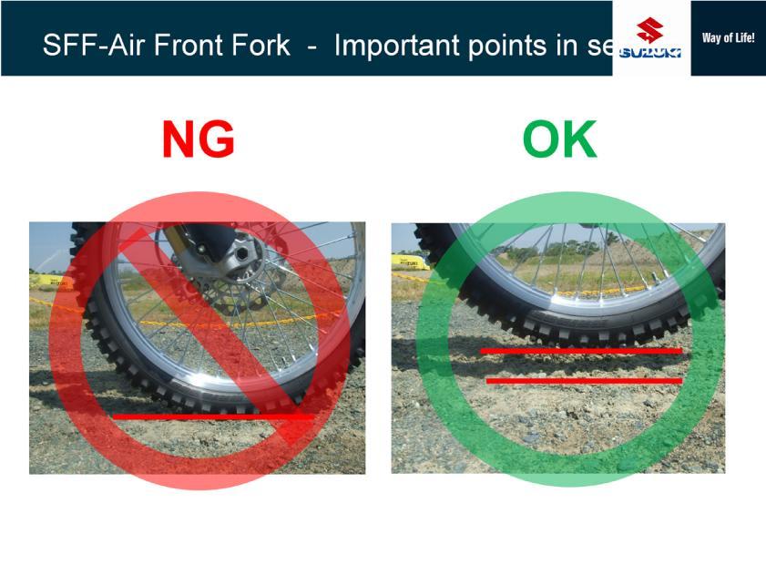
75 Air pressure check and adjustment must be done in condition that the front wheel is off from the ground. The specified air pressure value in the owner s service manual is determined in this free condition of the front fork. 74

76 Air adjustment in this condition cannot provide the correct setting. 75

77 Even in this condition, the fork inner tube is retracted by the machine own weight. Air adjustment in this condition also cannot provide the correct setting. 76

78 The front wheel must be lift up with a stand. 77
79 78

80 This is quick reference video showing the air charge and its order. Click the center of pictures with video icon to start short movies. 79
, 2nd Inner air (1200 kpa), 3rd inner air (0 kpa) (Note: Initial condition before air charging is 0 kpa in all 3 chambers.")
81 This slide shows bad example of front fork condition if air pressure is adjusted in the following incorrect order. Incorrect order: 1st balance air (1200 kpa), 2nd Inner air (1200 kpa), 3rd inner air (0 kpa) (Note: Initial condition before air charging is 0 kpa in all 3 chambers.) In this incorrect order, fork inner tube is retracted fully by the first air charging (1200 kpa) to the balance air chamber. Then after that, inner air chamber is pressurized to 1200 kpa and the inner tube is stretched and stopped as shown in the right picture. In this condition, the front fork does not work properly. Contrary to the above, in the correct order, fork inner tube is stretched fully by the first air charging (1200 kpa) to the inner air chamber. Then after that, balance air chamber is pressurized to 1200 kpa and the inner tube is retracted and stopped as shown in the left picture. As you can see, although you take the same pressure adjustment, the fork condition is quite different by the air charging order. 80

82 This slide explains why the difference of front fork in the previous slide occur. The piston stays in the center of injector with the balanced air pressure of 500 kpa. In this condition, if you charge air to 1000 kpa at the same time, the piston will stay in the same center position. 81

83 Different from the previous slide, if charging air to 1000 kpa from right side first and then charge air to 1000 kpa from the left, the piston will stop and stay at the left side of the injector body. By the first air charge from the right side, the piston moves to left and the left chamber s pressure increased from the original pressure 500 kpa. Then left chamber pressure can be increased to 1000 kpa by small amount charged from the left side. 82
 Secondary pressure in the outer air chamber is adjusted to zero. Finally air is charged to the balance air chamber to 1200 kpa.")
84 Imagine the injector drawing as the air front fork. For example of the air pressure adjustment to the standard setting: Firstly air is charged to the inner chamber to 1200 kpa. This makes the piston moving down. (fork inner tube is stretched.) Secondary pressure in the outer air chamber is adjusted to zero. Finally air is charged to the balance air chamber to 1200 kpa. This makes the piston moving up slightly. 83

85 Each of 3 air chambers requires the specified amount of fork oil. Unlike a conventional front fork, you need to pour fork oil into three air chambers one by one. Oil in each chamber slightly leaks down to balance air chamber gradually by repeated fork stroke during race over time, and neglecting the fork oil replacement may cause oil level change in the air chambers. And the oil level change affects the air volume of the 3 air chambers. And the remarkable air volume change will result in the setting. Air spring character changes by air volume if adjusted the same pressure.. On a conventional front fork, addition of fork oil amount over the specified amount makes fork setting hard. This mechanism is that the fork inner air becomes higher pressure by the fork stroke than the standard amount of fork oil due to the reduced inner air volume of front fork. Therefore, make sure to replace the front fork oil following the specified schedule 84

86 Oil may jet out from the valve when releasing air pressure. If the fork is lying on a desk, it allows the oil to move around the valve and enables oil jetting out when releasing air. To avoid the risk, place a rag around the valve when releasing air. 85

87 This is an extra explanation about motorcycle washing. In Suzuki owner s manual, use of high-pressure washer is prohibited because high water pressure may damage certain electric, engine chassis parts. 86

88 However some customer uses high pressure washer as shown in the picture. 87

89 As to high pressure washer using to clean a front fork, high pressure water jet may push mad and dust into the dust seal lip. Then the accumulated mad and dust at the dust seal rub the fork inner tube, and the mad and dust may cause damage of inner oil seal resulting in oil leakage. On SFF-Air fork, such seal damage causes air leakage which spoils air spring function. 88
2015 MOTOCROSS. Photo: RM-Z450 modified for AMA Supercross Championship
 2015 MOTOCROSS Photo: RM-Z450 modified for AMA Supercross Championship Photo : RM-Z450 modified for MX1 World Motocross Championship The holeshot can be yours, and that s just the beginning. The 2015 Suzuki
ATV 90 Y-12 YOUTH 2-STROKE RED (A2004ATB2BUSR) Page 1 of 52 A-ARM, FLOOR PANEL, AND BUMPER ASSEMBLY
 Page 1 of 52 A-ARM, FLOOR PANEL, AND BUMPER ASSEMBLY") 2004 ATV 90 Y-12 YOUTH 2-STROKE RED (A2004ATB2BUSR) Page 1 of 52 A-ARM, FLOOR PANEL, AND BUMPER ASSEMBLY 2004 ATV 90 Y-12 YOUTH 2-STROKE RED (A2004ATB2BUSR) Page 2 of 52 A-ARM, FLOOR PANEL, AND BUMPER
2004 ATV 90 Y-12 YOUTH 2-STROKE RED (A2004ATB2BUSR) Page 1 of 52 A-ARM, FLOOR PANEL, AND BUMPER ASSEMBLY 2004 ATV 90 Y-12 YOUTH 2-STROKE RED (A2004ATB2BUSR) Page 2 of 52 A-ARM, FLOOR PANEL, AND BUMPER
2003 CRF450R PRESS INFORMATION
 2003 CRF450R PRESS INFORMATION Cleared for take-off by the FIM in 2003, and primed to grab big air on motocross and supercross circuits the length and breadth of Europe, Honda s spectacular CRF450R has
Modifications or Removal Allowed( stroke machines only)
") DEVELOPMENT CLASS SUPPLEMENTARY REGULATIONS Development Class is open to any F4 Miniature Road Race bikes, 250cc 2 cylinder 4 stroke,including Hyosung cup machines and up to 150cc 2 and 4 stroke street
DEVELOPMENT CLASS SUPPLEMENTARY REGULATIONS Development Class is open to any F4 Miniature Road Race bikes, 250cc 2 cylinder 4 stroke,including Hyosung cup machines and up to 150cc 2 and 4 stroke street
Components for air preparation and pressure adjustment. OUT port position ( ) connected Rear side. of IN port. Air tank. directly.
 connected Rear side. of IN port. Air tank. directly.") Components preparation and pressure adjustment ABP Overview ABP is a component that enables boosting by s only up to twice primary pressure (.0MPa max.) in combination with using air tank but not using
Components preparation and pressure adjustment ABP Overview ABP is a component that enables boosting by s only up to twice primary pressure (.0MPa max.) in combination with using air tank but not using
K Page 1 of 48 Air Intake - Pg. 17
 K532-53168 Page 1 of 48 Air Intake - Pg. 17 Ref # Part Number Qty Description 24 25 041 06-S 1 Gasket, elbow 25 48 054 09 1 Elbow, air cleaner Discontinued not available at Kohler Co. 35 277116-S 1 Brace,
REAR SHOCK TUNING GUIDE
 REAR SHOCK TUNING GUIDE ridefox.com Sag setting To achieve the best performance from your FOX suspension, adjust the air pressure to attain your proper sag setting. Sag is the amount your suspension compresses
VACUUM REGULATORS CONTENTS
 CAD drawing data catalog is available. ACCESSORIES GENERAL CATALOG AIR TREATMENT, AUXILIARY, VACUUM, AND FLUORORESIN PRODUCTS CONTENTS Small Regulators Features 759 Specifications, Order Codes, Flow Rate
4 Machine maintenance and repair
 3.3 lift device consists of: lift motor, lead screw, guide rod, lifting seat Lift motor Lead screw Guide rod Lifting seat Diagram 3.3 3.4 torch holder set The torch holder consist of holder connection,
Spot Rollik 607 Suspension Setup Guide Table of Contents
 Spot Rollik 607 Suspension Setup Guide Table of Contents Warning Intended Use A. Rear Shock Pressure/Sag Setting B. Rear Shock Rebound Setting C. Rear Shock Compression Adjustment D. Rear Shock Volume
Priority (Swing) Motors Data and Specifications
 Motors Data and Specifications") s Data and Specifications Specifications HMF 55 HMF 75 HMF 105 cm 3/rev in 3/rev 55 3.36 75 4.57 105 6.40 Pressure Ratings Nominal 5000 PSIG Maximum 6090 PSIG Peak 7250 PSIG Operating Speed Maximum 4100
s Data and Specifications Specifications HMF 55 HMF 75 HMF 105 cm 3/rev in 3/rev 55 3.36 75 4.57 105 6.40 Pressure Ratings Nominal 5000 PSIG Maximum 6090 PSIG Peak 7250 PSIG Operating Speed Maximum 4100
REPAIR PART NUMBER NUMBER DESCRIPTION 0137 ELE 0136 ELE 12 VOLT SOLENOID
 PART REPAIR PART NUMBER NUMBER DESCRIPTION 0137 ELE 0136 ELE 12 VOLT SOLENOID 0203 WHL 0250 WHL WHEEL HUB 0251 WHL AXLE 0252 WHL DUST CAPS 0253 WHL TIRE - 210 SP 0204 WHL 0211 WHL TIRE & WHEEL - SP 0250
FOR IMMEDIATE RELEASE
 FOR IMMEDIATE RELEASE 11.August 2016 EUROPEAN PRESS INFORMATION 2017 HONDA CRF450RX Model updates: Honda now has a race-ready enduro machine: the CRF450RX is based on the all-new 17YM CRF450R and features
SUSPENSION SETUP GUIDE
 For your Pivot suspension equipped bike to pedal and descend at its best, it is important to tune the suspension properly. Use this guide to familiarize yourself with the Pivot suspension setup procedures
Power Valve: Precision Regulator. High precision, large capacity relief regulator
 Power Valve: Precision Regulator Series VEX High precision, large capacity relief regulator port large exhaust capacity pressure reducing valve which utilizes a nozzle flapper mechanism available as air
accidents which arise due to non-observance of these instructions and the safety information herein.
 3 GALLON PANCAKE COMPRESSOR Model: 50959 CALIFORNIA PROPOSITION 65 WARNING: You can create dust when you cut, sand, drill or grind materials such as wood, paint, metal, concrete, cement, or other masonry.
Lesson 6: Flow Control Valves
 : Flow Control Valves Basic Hydraulic Systems Hydraulic Fluids Hydraulic Tank Hydraulic Pumps and Motors Pressure Control Valves Directional Control Valves Flow Control Valves Cylinders : Flow Control
Model 130M Pneumatic Controller
 Instruction MI 017-450 May 1978 Model 130M Pneumatic Controller Installation and Operation Manual Control Unit Controller Model 130M Controller is a pneumatic, shelf-mounted instrument with a separate
TECHNICAL BENEFITS OF CJS / RAISE HSP. Technical Advantages
 TECHNICAL BENEFITS OF CJS / RAISE HSP Technical Advantages The HSP is designed for low- to mid- volume applications at flow rates of 1 cubic meter to 30 c. m per day. The benefits are in the details. The
REAR SHOCK TUNING GUIDE
 REAR SHOCK TUNING GUIDE ridefox.com Sag setting To achieve the best performance from your FOX suspension, adjust the air pressure to attain your proper sag setting. Sag is the amount your suspension compresses
DBML-60/80 Squeeze Tool
 DBML-60/80 Squeeze Tool OPERATORS MANUAL Description The Mustang Model DBML-60/80 Hydraulic squeeze tool has been manufactured since 1995. A Mustang 3 3/4 bore doubleacting cylinder producing 41,000 lbs
PACKSETTER HAND PUMP
 PACKSETTER HAND PUMP 1 CONTENTS Introduction...3 1. Product Description 3 2. Design Criteria.. 3 3. Risk Assessment Team.. 3 4. Objectives... 4 5. Hazard Classification...4+5 Risk matrix..6 FACTOR/INDEX
Model year 2014 USER MANUAL
 Model year 2014 USER MANUAL WARRANTY Terms and conditions BOS MTB offers warranty on its products on the following terms : BOS MTB guarantees to the original purchaser that the BOS product for which they
Exercise 2-3. Flow Rate and Velocity EXERCISE OBJECTIVE C C C
 Exercise 2-3 EXERCISE OBJECTIVE C C C To describe the operation of a flow control valve; To establish the relationship between flow rate and velocity; To operate meter-in, meter-out, and bypass flow control
Transfer Ktm Sx F 250 Repair Manual
 Transfer Ktm Sx F 250 Repair Manual Download: ktm-sx-f-250-repair-manual.pdf Read: ktm sx f 250 repair manual Take a look at this ktm sx f 250 repair manual side turn signal lamp assy view and download
CHAPTER 9 PROPELLERS
 CHAPTER 9 CHAPTER 9 PROPELLERS CONTENTS PAGE How Lift is Generated 02 Helix Angle 04 Blade Angle of Attack and Helix Angle Changes 06 Variable Blade Angle Mechanism 08 Blade Angles 10 Blade Twist 12 PROPELLERS
TECHNICAL DATA - ENGINE 89
 TECHNICAL DATA - ENGINE 89 13 TECHNICAL DATA - ENGINE Design Displacement (all 400 models) Displacement (all 450 models) Displacement (all 530 models) Stroke (all 400 models) Stroke (all 450 models) Stroke
Ball valve HKSF-W100. Ball valve HKSF-W100. RMA Kehl GmbH & Co. KG Oststrasse 17 D Kehl / Germany
 Ball valve HKSF-W100 RMA Kehl GmbH & Co. KG Oststrasse 17 D-77694 Kehl / Germany info@rma-kehl.de www.rma-armaturen.de 1 Design Features: RMA-ball valves type HKSF-W are fully welded and completely maintenance-free
IWCF Equipment Sample Questions (Combination of Surface and Subsea Stack)
") IWCF Equipment Sample Questions (Combination of Surface and Subsea Stack) 1. Given the volumes below, how much hydraulic fluid will be required to carry out the following operations (no safety margin)?
IWCF Equipment Sample Questions (Combination of Surface and Subsea Stack) 1. Given the volumes below, how much hydraulic fluid will be required to carry out the following operations (no safety margin)?
P R O D U C T G U I D E E N D U R O - M O T O C R O S S
 PRODUCT GUIDE PRODUCT GUIDE Husqvarna s legacy represents a unique chapter in the story of motorcycles.with a history spanning over 100 years, our bikes have dominated all off-road categories, allowing
FLUID POWER FLUID POWER EQUIPMENT TUTORIAL OTHER FLUID POWER VALVES. This work covers part of outcome 2 of the Edexcel standard module:
 FLUID POWER FLUID POWER EQUIPMENT TUTORIAL OTHER FLUID POWER VALVES This work covers part of outcome 2 of the Edexcel standard module: UNIT 21746P APPLIED PNEUMATICS AND HYDRAULICS The material needed
Air Operated Hydraulic Pumping Systems to 50,000 psi
 High Pressure Equipment Air Operated Hydraulic Pumping Systems to 50,000 psi PS-10: 10,000 psi PS-20: 20,000 psi PS-30: 30,000 psi PS-40: 40,000 psi PS-50: 50,000 psi PS-90: 90,000 psi High Pressure air
DM-MBST (English) Dealer's Manual. ROAD MTB Trekking. City Touring/ Comfort Bike. Shifting lever. EZ-FIRE Plus ST-EF500 ST-EF510
 Dealer's Manual. ROAD MTB Trekking. City Touring/ Comfort Bike. Shifting lever. EZ-FIRE Plus ST-EF500 ST-EF510") (English) DM-MBST001-00 Dealer's Manual ROAD MTB Trekking City Touring/ Comfort Bike URBAN SPORT E-BIKE Shifting lever EZ-FIRE Plus ST-EF500 ST-EF510 CONTENTS IMPORTANT NOTICE... 3 TO ENSURE SAFETY...
(English) DM-MBST001-00 Dealer's Manual ROAD MTB Trekking City Touring/ Comfort Bike URBAN SPORT E-BIKE Shifting lever EZ-FIRE Plus ST-EF500 ST-EF510 CONTENTS IMPORTANT NOTICE... 3 TO ENSURE SAFETY...
INSTALLATION INSTRUCTIONS
 INSTALLATION INSTRUCTIONS HIGH PRESSURE PUMP To minimize vibration, it is best to build brackets on the motor itself, similar to alternator brackets. Use cardboard to construct a pattern first before making
EZee Glider Manual. Tools needed for Assembly: Wrench (included) Philips Screwdriver (not included) Assembly Instructions
 Philips Screwdriver (not included) Assembly Instructions") EZee Glider Manual Congratulations on your purchase of the EZee Glider! Your glider is designed for years of nearly carefree use by your child. These instructions include how to set up your glider and
EZee Glider Manual Congratulations on your purchase of the EZee Glider! Your glider is designed for years of nearly carefree use by your child. These instructions include how to set up your glider and
ASSEMBLY GUIDE AROUND THE BLOCK - 1, 3, 7, & 21 SPEED SIXTHREEZERO
 ASSEMBLY GUIDE AROUND THE BLOCK - 1, 3, 7, & 21 SPEED SIXTHREEZERO OUR COMMITMENT We want you to love your bike as much as we do. If you run into any issues, no matter how small, let us know and we ll
 Worldwide 1.800.FOX.SHOX (1.800.369.7469) FORK- 2014 34 FLOAT 27.5 Travel 5.5 in./140 mm 5.9 in./150 mm 6.3 in./160mm Features/Adjustments Factory FIT CTD w/adj; 140, 150, 160; Kashima Coated or anodized
EXH. Specifications. Descriptions. Min. working pressure MPa
 Functional explanation Primary pressure flowed from passes through check valve on side, and flows in chamber A and B. Primary pressure also passes through pressure adjustment section and switching valve,
SPECIFICATIONS Type: Twin stack, single phase Tank: 4 gallon Air Output: PSI; PSI Max PSI: 125 PSI HP: 1.
 2 GALLON TWIN STACK AIR COMPRESSOR Model: 9526 DO NOT RETURN TO STORE. Please CALL 800-348-5004 for parts and service. CALIFORNIA PROPOSITION 65 WARNING: You can create dust when you cut, sand, drill or
30T A/Manual Hydraulic Shop Press
 30T A/Manual Hydraulic Shop Press Operation Manual 1 1. Important Information 1.1 Safety Information 1.1.1 Hazard Symbols Used in the Manuals This manual includes the hazard symbols defined below when
Model Copyright 2012 by General Machine Products (KT), LLC
, LLC") LIGHTWEIGHT CAPSTAN WINCH OPERATION & MAINTENANCE MANUAL Model 70627 Copyright 2012 by All rights reserved. No part of this publication may be copied, reproduced or transmitted in any form whatsoever without
LIGHTWEIGHT CAPSTAN WINCH OPERATION & MAINTENANCE MANUAL Model 70627 Copyright 2012 by All rights reserved. No part of this publication may be copied, reproduced or transmitted in any form whatsoever without
100L AIR COMPRESSOR MODEL NO: TIGER 16/1010 PART NO: OPERATION & MAINTENANCE INSTRUCTIONS LS01/13
 100L AIR COMPRESSOR MODEL NO: TIGER 16/1010 PART NO: 2244025 OPERATION & MAINTENANCE INSTRUCTIONS LS01/13 INTRODUCTION Thank you for purchasing this product. Before attempting to use this product, please
ASVAD THE SIMPLE ANSWER TO A SERIOUS PROBLEM. Automatic Safety Valve for Accumulator Depressurization. (p.p.)
") ASVAD Automatic Safety Valve for Accumulator Depressurization (p.p.) THE SIMPLE ANSWER TO A SERIOUS PROBLEM International Experts Meeting on Strengthening Research and Development Effectiveness in the
ASVAD Automatic Safety Valve for Accumulator Depressurization (p.p.) THE SIMPLE ANSWER TO A SERIOUS PROBLEM International Experts Meeting on Strengthening Research and Development Effectiveness in the
ATM 322 Basic Pneumatics H.W.6 Modules 5 7
 ATM 322 Basic Pneumatics H.W.6 Modules 5 7 Name: Answer Key Mark: Question I: Write (T) for True and (F) for false sentences. A) For the time dependant process control; Step enabling conditions are generated
Introduction to Pneumatics
 Introduction to Pneumatics Pneumatics Symbols Air generation and distribution Table 1: Symbols use in energy conversion and preparation ITEM SYMBOL MEANING Compressor SUPPLY Pressure Source Pneumatic Pressure
Bombardier Inc. All rights reserved 1995 Bombardier Inc. Trademark of Bombardier Inc. Litho'd in Canada
 Bombardier Inc. VOLUME 2 FLAT RATE TIME SCHEDULE 1996 Mach 1 Formula STX/LT2 Formula SLS Summit 500 Grand Touring 500/580/SE All rights reserved 1995 Bombardier Inc. Trademark of Bombardier Inc. Litho'd
SpeciÞcations. Engine Dimensions Dimensions in millimeters. Inch equivalents shown in [].
![SpeciÞcations. Engine Dimensions Dimensions in millimeters. Inch equivalents shown in [].](/thumbs/77/75006228.jpg "SpeciÞcations. Engine Dimensions Dimensions in millimeters. Inch equivalents shown in [].") SpeciÞcations Engine Dimensions Dimensions in millimeters. Inch equivalents shown in []. Ê ßÔ Ê ÛÝ Ñ Ê Û ÎÊ Û É 5 ENGINE IDENTIFICATION NUMBERS Kohler engine identiþcation numbers (model, speciþcation
SpeciÞcations Engine Dimensions Dimensions in millimeters. Inch equivalents shown in []. Ê ßÔ Ê ÛÝ Ñ Ê Û ÎÊ Û É 5 ENGINE IDENTIFICATION NUMBERS Kohler engine identiþcation numbers (model, speciþcation
Pressure Sensing Valve - Model 4023
 Pressure Sensing Valve - Model 4023 Overview AMOT Model 4023 can be used as a 2 or 3-way capacity, pressure sensing valve. This valve is ideal for applications that require compressor suction and discharge
WORLD CHAMPION. SMALL BORE RIFLE.22 l.r. MANUAL. Technical Innovations
 SMALL BORE RIFLE.22 l.r. MANUAL Technical Innovations Technical Innovations -General information Page 2 -Bedding Page 3 -Three locking lugs Page 4 -Safety / dry fire switch Page 4 -Firing pin Page 4 -Firing
OFF-ROAD ROBUST LESS MAINTENANCE EASY TO MOUNT EXCELLENT MODULATION
 OFF-ROAD ROBUST LESS MAINTENANCE EASY TO MOUNT EXCELLENT MODULATION 18 OFF-ROAD 19 MAGURA BLOOD Breakaway lever Carbon tubing REACH ADJUST Mirror mount EASY MOUNT FROM CNI TO BLACK RHR Rotatable Hose Routing
ShellPa. Standard Mechanical Cell Stretch System Model No: NNMS Serial #: User Manual
 ShellPa Standard Mechanical Cell Stretch System Model No: NNMS Serial #: User Manual To operate the system properly and safely, read the manual before using ShellPa. This system is not a medical device.
Vibration isolation system 1VIS10W. User manual
 Vibration isolation system 1VIS10W User manual Standa 2014 Table of contents 1. General information 3 1.1. Introduction 3 1.1.1. Safety 5 1.2. Location of the table 5 1.3. Air supply requirements 5 2.
24L AIR COMPRESSOR OPERATION & MAINTENANCE INSTRUCTIONS MODEL NO: RANGER 7/240 PART NO: LS0913
 24L AIR COMPRESSOR MODEL NO: RANGER 7/240 PART NO: 2242000 OPERATION & MAINTENANCE INSTRUCTIONS LS0913 INTRODUCTION Thank you for purchasing this CLARKE 24L Air Compressor. Please read this manual fully
Troubleshooting Guide
 Troubleshooting Guide This troubleshooting guide outlines quick fixes to the most common technical questions about the ElliptiGO. If the problem persists or you feel uncomfortable performing these actions,
SPECIFICATIONS TABLE Maximum Air Pressure 115 PSI Air Tank Capacity 20 Gallons
 SPECIFICATIONS TABLE Maximum Air Pressure 115 PSI Air Tank Capacity 20 Gallons Air Flow Capacity 6.2 CFM at 40 PSI 5.2 CFM at 90 PSI Motor 2.5 HP Working / 4 HP Peak 120 Volt / 60 Hz / 13 A / 1-Phase Required
then the work done is, if the force and the displacement are in opposite directions, then the work done is.
 1. What is the formula for work? W= x 2. What are the 8 forms of energy? 3. Write the formula for the following: Kinetic Energy Potential Energy 4. If the force and the displacement are in the same direction,
Index Table. Model 794. Installation, Operating and Maintenance Instructions
 CLOCKWISE MANUAL MAKING INTO CCW TABLE Index Table Model 794 Installation, Operating and Maintenance Instructions Black & Webster Products Division 545 Hupp Ave. P.O. Box 831, Jackson, Michigan 49204 2009
SG-7R46 SG-7R45 BR-IM41-R CJ-7S40 WARNING CAUTION SERVICE INSTRUCTIONS. Inter-7 Hub. Inter-M Brake Cassette joint NOTE:
 t WARNING It is important to completely understand the operation of your bicycle's brake system. Improper use of your bicycle's brake system may result in a loss of control or an accident, which could
Erik Backström, High Voltage breakers, After Sales & Service High voltage SF 6 live tank circuit breakers After Sales & Service Training course
 Erik Backström, High Voltage breakers, After Sales & Service High voltage SF 6 live tank circuit breakers After Sales & Service Training course description LTB72,5-170 D with BLK222 & FSA1 Level A & B
Basic Pneumatics. Module 7: Time delay valve and sequence control systems. Academic Services PREPARED BY. January 2013
 Basic Pneumatics Module 7: Time delay valve and sequence control systems PREPARED BY Academic Services January 2013 Applied Technology High Schools, 2013 Module 7: Time delay valve and sequence control
HYDRAULIC CYLINDER TEST
 In the event that a coach equipped with hydraulic slide-outs begins to experience room drift, whether the room drifts out after retract, or drifting in after extension, a test of the hydraulic cylinders
AIRCRAFT PRIMARY CONTROLS A I R C R A F T G E N E R A L K N O W L E D G E
 1.02.02 AIRCRAFT PRIMARY CONTROLS 1. 0 2 A I R C R A F T G E N E R A L K N O W L E D G E CONTROLLING AIRCRAFT AIRCRAFT CONTROL SYSTEM In general, we use control inputs of the following devices in cabin:
VAC-U DRIVE Swinging float arm for Acrobat like agility 36 Fin disk with DEEP VEE Scoop
 ACROBAT Vac-U-Drive Automatic Pool Cleaner VAC-U DRIVE Swinging float arm for Acrobat like agility 36 Fin disk with DEEP VEE Scoop Proven technology:diaphragm driven strength & quietness Unique hose design
Hydro-Pneumatic Cylinder HPL-B / HPL-C
 Ihr flexibler Problemlöser in der Fluidtechnik Hydro-Pneumatic Cylinder HPL-B / HPL-C DRUMAG GmbH Fluid Technology Glarnerstraße 2 D-79713 Bad Säckingen Telefone: +49 (0)7761 / 5505-0 Fax: +49 (0)7761
Inside Front cover This page will remain blank.
 Owner s Manual Inside Front cover This page will remain blank. 1 Table of Contents Parts of the AirCAT...3 Assembling the AirCAT...4 Attaching the wheels to the stand...4 Attaching the battery box to the
Controllers DR, DP, FR and DFR
 Controllers DR, DP, FR and DFR RE 9060 Edition: 04.014 Replaces: 10.006 For variable pump A4VSO series 1 and 3 Open circuit Features Control of pressure and flow Remote controlled optional Pressure controller
Operation & Maintenance Manual Place this manual with valve or person responsible for maintenance of the valve
 Operation & Maintenance Manual Place this manual with valve or person responsible for maintenance of the valve Model CYCLE GARD II, CI & CNA YOUR PRODUCT INFORMATION: Model Number: Date: Serial Number:
Operation Manual - PN A MENSOR MODEL 73 SHOP AIR BOOSTER
 Operation Manual - PN 0017946001 A MENSOR MODEL 73 SHOP AIR BOOSTER Mensor Model 73 Shop Air Booster System (750 psi Version) April 23, 2012 Trademarks / Copyright Mensor is a registered trademark of Mensor
Beta UK 2018 SSDT Preparation Guide
 Beta UK 2018 SSDT Preparation Guide For SSDT riders on confirmation of entry please telephone Gary (+44 (0)1756 793521) to sign on for our back up service, inform him of your riding number and which bike
(Refer Slide Time: 0:26)
") Fundamentals of Industrial Oil Hydraulics and Pneumatics By Professor R. Maiti Department of Mechanical Engineering Indian Institute of Technology, Kharagpur Module03 Lecture08 Different Types of Valves-
Fundamentals of Industrial Oil Hydraulics and Pneumatics By Professor R. Maiti Department of Mechanical Engineering Indian Institute of Technology, Kharagpur Module03 Lecture08 Different Types of Valves-
OPERATING INSTRUCTIONS
 OPERATING INSTRUCTIONS Air Entrainment Meter ELE International Chartmoor Road, Chartwell Business Park Leighton Buzzard, Bedfordshire, LU7 4WG England phone: +44 (0) 1525 249200 fax: +44 (0) 1525 249249
DM-RARD (English) Dealer's Manual. ROAD MTB Trekking. City Touring/ Comfort Bike. Rear Derailleur DURA-ACE RD-R9100 ULTEGRA RD-R8000
 Dealer's Manual. ROAD MTB Trekking. City Touring/ Comfort Bike. Rear Derailleur DURA-ACE RD-R9100 ULTEGRA RD-R8000") (English) DM-RARD001-03 Dealer's Manual ROAD MTB Trekking City Touring/ Comfort Bike URBAN SPORT E-BIKE Rear Derailleur DURA-ACE RD-R9100 ULTEGRA RD-R8000 CONTENTS IMPORTANT NOTICE... 3 TO ENSURE SAFETY...
(English) DM-RARD001-03 Dealer's Manual ROAD MTB Trekking City Touring/ Comfort Bike URBAN SPORT E-BIKE Rear Derailleur DURA-ACE RD-R9100 ULTEGRA RD-R8000 CONTENTS IMPORTANT NOTICE... 3 TO ENSURE SAFETY...
24 Litre Air Compressor
 Operator s Manual 24 Litre Air Compressor WARNING! Before using this appliance, read the Operator s manual and follow all its safety rules and instructions. SPECIFICATION Model Power ITEM DATA HWKAC2 1Kw/1.5HP&1.5Kw/2HP&1.8Kw/2.5HP
Hydraulic Punch Drivers
 SERVICE MANUAL 7804SB / 7806SB Quick Draw 7704SB / 7706SB Quick Draw Flex Quick Draw Hydraulic Punch Drivers Serial Codes AHJ and YZ Read and understand all of the instructions and safety information in
Tradition & Technology
 Gaterotor Support Gaterotor Single Screw Compressors Design & Operation Bearing Bearings Main Screw Parallex Slide System The VSM Single Screw Compressor has one main rotor and two gaterotors. All bearings
Introduction. Part one: Identify the Hydraulic Trainer Components
 The University Of Jordan School of Engineering Mechatronics Engineering Department Fluid Power Engineering Lab Experiments No.4 Introduction to Hydraulic Trainer Objective: Students will be able to identify
24L OIL FREE AIR COMPRESSOR MODEL NO: TIGER 7/250 PART NO: OPERATION & MAINTENANCE INSTRUCTIONS LS10/13
 24L OIL FREE AIR COMPRESSOR MODEL NO: TIGER 7/250 PART NO: 2244030 OPERATION & MAINTENANCE INSTRUCTIONS LS10/13 INTRODUCTION Thank you for purchasing this product. Before attempting to use this product,
GX200 QX2 ENGINE, JPN, VIN# GCAE Page 1 of 34 AIR CLEANER (DUAL)
") GX200 QX2 ENGINE, JPN, VIN# GCAE-1000001 Page 1 of 34 AIR CLEANER (DUAL) GX200 QX2 ENGINE, JPN, VIN# GCAE-1000001 Page 2 of 34 Ref # Part Number Qty Description AIR CLEANER (DUAL) 1 16271-ZE1-000 1 GASKET,
GX200 QX2 ENGINE, JPN, VIN# GCAE-1000001 Page 1 of 34 AIR CLEANER (DUAL) GX200 QX2 ENGINE, JPN, VIN# GCAE-1000001 Page 2 of 34 Ref # Part Number Qty Description AIR CLEANER (DUAL) 1 16271-ZE1-000 1 GASKET,
MAINTENANCE PROCEDURE FOR X 650
 MAINTENANCE PROCEDURE FOR X 650 X 650 25. juli 2005-1/6 MAINTENANCE PROCEDURE FOR X 650 2 ND STAGE WARNING: This maintenance procedure is only for appointed Scubapro technicians that completed a course
Inoxair. Repair Manual. Content. Edition: 12/2010. Subject to technical changes for reasons of the continous development.
 Inoxair Repair Manual Edition: 12/2010 Content 1) Serial number 2) Technical data 3) Functional principle 4) Problem analysis 5) Removal 6) Repairs 7) Circuit diagram and cable-connection-plan 8) Pneumatic
Owner s Guide. ElevateSUP.com
 Owner s Guide ElevateSUP.com IMPORTANT READ THIS IMPORTANT INFORMATION BEFORE USING YOUR STAND UP PAD- DLEBOARD Disregarding any of the safety precautions and instructions contained in the owner s manual
RC 195 Receiver-Controller
 Document No. 129-082 RC 195 Receiver-Controller Product Description The POWERS RC 195 Receiver-Controller is a pneumatic instrument that receives one, two or three pneumatic inputs. It produces a pneumatic
Model 7989T Steel Pipe Squeezer Sch. 40 & Sch. 80. Operations Manual
 10-12 Steel Pipe Squeezer Sch. 40 & Sch. 80 Operations Manual 1.0 Introduction This manual is issued as a basic operation manual covering the Regent Model 7989T, Pipe Squeezer and Pump as manufactured
Mini Glider Manual. Your Glider comes partially assembled. The front wheel and the handlebars require assembly.
 Mini Glider Manual Congratulations on your purchase of the Mini Glider! Your glider is designed for years of nearly carefree use by your child. These instructions include how to set up your glider and
ALL TERRAIN CRANE AR-1200M-1
 ALL TERRAIN RANE AR-12M JAPANESE SPEIFIATIONS ARRIER MODEL FAUN RTF12-5 SPE. NO. AR-12M-1 AR ontrol No. JA-3-279 - Return to INDEX AR-12M RANE SPEIFIATIONS RANE APAITY 12.2m Boom 12,kg at 2.7m (17part-line)
Copyright, 2005 GPM Hydraulic Consulting, Inc.
 Troubleshooting and Preventive Maintenance of Hydraulic Systems Learning to Read the Signs of Future System Failures Instructed by: Al Smiley & Alan Dellinger Copyright, 2005 GPM Hydraulic Consulting,
Product Information News September 26, 2003
 Product Information News September 26, 2003 LEVER HEIGHT INSPECTION FOR FIREHAWK MMR MSA is announcing a revision to the instructions for the Firehawk MMR Second Stage Regulator as they relate to the air
Heat Engine. Reading: Appropriate sections for first, second law of thermodynamics, and PV diagrams.
 Heat Engine Equipment: Capstone, 2 large glass beakers (one for ice water, the other for boiling water), temperature sensor, pressure sensor, rotary motion sensor, meter stick, calipers, set of weights,
Simplicity in VRU by using a Beam Gas Compressor
 Simplicity in VRU by using a Beam Gas Compressor By Charlie D. McCoy and Mark Lancaster Abstract: Vapor Recovery Units are often expensive, complicated to operate and unable to deal with High H2S and liquids.
Chapter 10: Bidirectional Flow Controls
 Chapter 10: Bidirectional Flow Controls Objectives Learn about the patented, bidirectional flow control valves. Understand how the flow force affects the performance of the ZL70-36. Learn why there is
Self Contained Propane Powered Hammer Owner s Manual. by Tippmann. rev. # 2:
 TM Self Contained Propane Powered Hammer Owner s Manual by Tippmann rev. # 2: 6-1-2008 TM CONGRATULATIONS on the purchase of your Tippmann Propane Hammer. We believe the Tippmann Propane Hammer is the
OPERATING INSTRUCTIONS. Parts List N. Note: Owner and operator MUST read and understand this operating instructions before use this lift table.
 OPERATING INSTRUCTIONS Parts List 770N te: Owner and operator MUST read and understand this operating instructions before use this lift table. Thank you for using this lift table. Your lift table is made
Budget Range Operators Handbook
 Budget Range Operators Handbook BAMBI AIR COMPRESSORS LTD 152 Thimble Mill Lane Heartlands Birmingham B7 5HT United Kingdom Tel: 0121 322 2299 Fax: 0121 322 2297 Email: sales@bambi-air.co.uk www.bambi-air.co.uk
955108_2. AirForce Operator s Guide
 955108_2 AirForce Operator s Guide Contents System Setup and Operation...3 AirForce Setup...3 Load Cells...6 AirForce Control...8 How to Set AirForce...11 Home Screen...13 AirForce Diagnostic Information...15
WW-720. Pressure Reducing Control Valve
 WW-720 Pressure Reducing Control Valve (Size Ranges: 2-4 and 6-14 ) Installation Operation & Maintenance Page 1 of 6 1. DESCRIPTION The Model 720 Pressure Reducing is an automatic control valve (powered
MODEL 200 KNIFE GATE VALVES INSTALLATION & MAINTENANCE MANUAL
 MODEL 200 KNIFE GATE VALVES INSTALLATION & MAINTENANCE MANUAL Index 1. List of components / General arrangement 2. Description 3. Handling 4. Installation 5. Actuators / Operation 6. Maintenance a. Changing
Please visit our website at and leave your comments.
 We promise our customers the best services and premium quality products with value. MODIFY and its logo are registered trademarks. Please visit our website at www.modify.com.tw and leave your comments.
I T T Pressure Reducing Valve WARNING INSTALLATION, OPERATION, AND MAINTENANCE MANUAL
 INSTALLATION, OPERATION, AND MAINTENANCE MANUAL I-867-4T 867-4T Pressure Reducing Valve HANG THESE INSTRUCTIONS ON THE INSTALLED VALVE FOR FUTURE REFERENCE WARNING Read and understand all instructions
Powers Controls RC 195 Multiple Input Receiver- Controller
 Powers Controls RC 195 Multiple Input Receiver- Controller Document No. 155-036P25 RC 195-1 Description Features Application The RC 195 Multiple lnput Receiver-Controller is a pneumatic instrument which
OWNER S TECHNICAL MANUAL
 EL SERIES OWNER S TECHNICAL MANUAL DP7002 1 Air Operated Diaphragm Pump Description The DP7002 1 air operated diaphragm pump is the ideal device for the pumping, transfer and dispensing of chemical liquids,