Status Date Prepared Reviewed Endorsed Approved
|
|
|
- Daisy Small
- 5 years ago
- Views:
Transcription


1 Discipline Engineering Standard NSW Category Signalling Title Typical Inspections and Tests for Signalling Apparatus Procedures for Alterations Reference Number SCP 12 (RIC Standard: SC SP) Document Control Status Date Prepared Reviewed Endorsed Approved Mar 05 Standards and Systems Refer to Reference Number Standards Engineer H Olsen GM Infrastructure Strategy & Performance M Owens Safety Committee Refer to minutes of meeting 12/08/04
2 DISCLAIMER Australian Rail Track Corporation has used its best endeavours to ensure that the content, layout and text of this document is accurate, complete and suitable for it s stated purpose. It makes no warranties, express or implied, that compliance with the contents of this document shall be sufficient to ensure safe systems of work or operation. Australian Rail Track Corporation will not be liable to pay compensation in respect of the content or subsequent use of this document for any other purpose than its stated purpose or for any purpose other than that for which it was prepared except where it can be shown to have acted in bad faith or there has been wilful default. DOCUMENT APPROVAL The technical content of this document has been approved by the relevant ARTC engineering authority and has also been endorsed by the ARTC Safety Committee. DOCUMENT SUPPLY and CONTROL The Primary Version of this document is the electronic version that is available and accessible on the Australian Rail Track Corporation Internet and Intranet website. It is the document user s sole responsibility to ensure that copies are checked for currency against the Primary Version prior to its use. COPYRIGHT The information in this document is Copyright protected. Apart from the reproduction without alteration of this document for personal use, non-profit purposes or for any fair dealing as permitted under the Copyright Act 1968, no part of this document may be reproduced, altered, stored or transmitted by any person without the prior written consent of ARTC. March 2005 Page 2 of 23
3 About This Standard This Specification sets out the requirements for the implementation of an effective system for verification and assurance of the safety integrity of the signalling system, and for verification and assurance of the compliance to specification of the new and/or altered signalling system when commissioned. March 2005 Page 3 of 23
4 Document History Primary Source RIC Standard SC SP Version 2.0 List of Amendments ISSUE DATE CLAUSE DESCRIPTION /09/2004 Reformatting to ARTC Standard /03/2005 Disclaimer Minor editorial change Footer reformatted 13/08/2010 ALL Superseded by ESC March 2005 Page 4 of 23
5 Contents About This Standard... 3 Version History General Requirements For Alterations, Renewals And Repairs Modifications, Renewals and Repairs Authority for Alterations to Existing Installation Approval to Commence Alterations Performance and Liaison Detailed Site Assessment (Site Integrity Agreement) Precautions to be Agreed Inspection, Testing and Certification of Alterations Instructions When Working Near Or Altering Existing Signalling Isolation from Working Circuits Mixing of Old and New Circuits Loose Wires or Crimps Connection or Disconnection from Vital Circuits Interference with Working Circuits, Security of Signalling Locations Wiring Not In Use Tagging of Wiring at Termination Points Labelling of Stagework Temporary Wiring Stagework Testing Colours Control and Removal of Temporary Wiring Spare Wires Equipment Not in Use Insulating the Wire and Equipment Not in Use Test Equipment Use of Spares or Re-use of Existing Equipment Interfacing of New and Existing Work Modifications To Existing Circuits Existing Circuit to be Checked and Labelled before Alteration Precautions when Modifying portion of a Circuit Label points of connection, disconnection Build up New Circuitry Changeover Redundant Wiring to be Removed Testing the Altered Circuit March 2005 Page 5 of 23
6 3.8 Certainty of Circuit Status Procedures for Modifications to Existing Circuits Modifications on a Large Scale March 2005 Page 6 of 23
7 1. General Requirements For Alterations, Renewals And Repairs 1.1 Modifications, Renewals and Repairs Where vital signalling equipment and/or circuits are modified, renewed or repaired there may be a risk that the signalling could be altered to function incorrectly and it is necessary to ensure that the changes are tested and certified to function correctly and to conform with the approved designs. The testing necessary will need to cover the risk involved and this risk shall be minimised by strict adherence to alteration precautions and procedures. 1.2 Authority for Alterations to Existing Installation The Signal Design Authority for approving design alterations to existing installations (in accordance with documented ARTC standards) shall be a person granted such authorisation by the ARTC General Manager ISP or nominated Signalling representative or by an authorising agent representing ARTC as determined by the ARTC GM ISP or nominated Signalling representative. Design alterations to an existing system shall not be carried out without that authority. Unless otherwise approved, the authority for changes shall be in the form of approved design documentation. Alterations include the following: i) Alterations to electrical or mechanical configuration eg., circuit wiring. ii) Changing items of equipment to a different type, make, or model. Any difficulty with the issued alterations is to be referred to the Signal Design Authority for clarification and direction. Modifications to issued design alterations shall be approved by the Signal Design Authority and formerly issued before alteration to working circuits. Field staff shall ensure that all copies of issued design alterations are promptly corrected and updated with modifications and they shall keep each copy properly bound, secure and in good condition. Where an alteration which does not affect the principle of a working circuit is necessary in emergencies and it is not practical to obtain authority from the Signal Design Authority, viz under failure conditions to change from a defective relay contact or defective cable core to a spare relay contact or spare cable core, the Signal Design Authority shall be advised of the change in writing promptly and without delay and written acknowledgment obtained from the Signal Design Authority that the information has been received. March 2005 Page 7 of 23
8 1.3 Approval to Commence Alterations Authorised alterations also require the approval of the local maintenance Signal Engineer before the alteration work can commence. 1.4 Performance and Liaison Where alterations are not carried out by staff under the direction of the local Signal Engineer, there must be a full liaison between the installation staff and the local maintenance Signal Engineer and maintenance staff. 1.5 Detailed Site Assessment (Site Integrity Agreement) Prior to any significant alteration, addition, or renewal of wiring, or a relay change programme, being commenced, a detailed site assessment of the condition of the location and the ability of the existing wiring and equipment to withstand disturbance is be carried out by the Project Engineer, Construction, the Commissioning Engineer and the local maintenance Signal Engineer. 1.6 Precautions to be Agreed All precautions to minimise disturbance to the existing equipment and damage to buried cables are to be agreed by the Commissioning Engineer and the local maintenance Signal Engineers and are to be documented. The Project Engineer, Construction, the local maintenance Signal Engineer and the Commissioning Engineer are to agree on the condition of the location and of the equipment installed. They are to agree on preparatory work needed, precautions to be adopted, and on the method of working that will ensure the existing signalling system is not endangered by the project work, particularly where the wire insulation or equipment may be old or fragile, where labelling is not adequate, where the accuracy of the circuit book is not certain or any other vulnerable situation. Details of insulation records are to be noted. Prior to work commencing they are to ensure that the location is in a clean and tidy condition, that there are no loose wires or connections, that any unterminated wires are cut back and covered, and that there are not pieces of wire, bits of metal, loose washers or other extraneous objects etc., in the location. The Project Engineer, Construction, the maintenance Signal Engineer and the Commissioning Engineer shall agree on who will carry out the preparatory work required to remove any potential hazards. The agreement for each inspected location shall be written down as part of the scope of works and signed by the Project Engineer, Construction, the local maintenance Signal Engineer and the Commissioning Engineer before the maintenance Signal Engineer authorises work to commence in the location. Once project work starts in a location the project team become accountable for conditions that arise resulting partly or wholly from their work; from that March 2005 Page 8 of 23
9 time, district staff are not to carry out any work in the location that interferes with the equipment or wiring, except in emergency or as agreed between the Project Engineer, Construction, the Commissioning Engineer and the local maintenance Signal Engineer. Details of such work are to be recorded. The project staff shall work within the agreement and will be accountable for ensuring that the existing signalling system is not endangered by work in the location. The documented safeguards are to be approved by the local maintenance Signal Engineer. 1.7 Inspection, Testing and Certification of Alterations Inspection, testing and certification of design alterations of existing vital signalling shall be based on the inspection, testing and certification principles and procedures applying to New and Altered Works. March 2005 Page 9 of 23
10 2. Instructions When Working Near Or Altering Existing Signalling Below are instructions that shall be followed when involved in alterations to existing circuits or when working near existing circuits. 2.1 Isolation from Working Circuits Wires and equipment, de-commissioned from use, or not yet commissioned into use shall not be connected at any point to working signalling circuits or power supplies and must be secured against and insulated from any possible metallic contact with working circuits. 2.2 Mixing of Old and New Circuits If new wiring is to tap into old circuits, the new wiring shall not be connected into the existing working circuit before commissioning the new wiring into use. 2.3 Loose Wires or Crimps Loose wires with exposed conductors or with exposed crimps or lugs etc shall not be left unterminated near working circuits or equipment. They shall be clearly labelled and have their ends secured and insulated to prevent contact with one another or with any other equipment. 2.4 Connection or Disconnection from Vital Circuits For new work and alterations, wires or equipment shall only be connected into or disconnected from vital signalling circuits when the affected signalling apparatus is disconnected and formally booked out of use. 2.5 Interference with Working Circuits, Security of Signalling Locations All precautions shall be taken to ensure that working circuits cannot be mistakenly interfered with, accidentally damaged, or shorted out by tools, loose relay nuts, washers, bits of wire, etc. All vital equipment and locations shall be fitted with locks and be locked when unattended. Before closing up equipment or locations, persons shall check that everything is in order and properly connected and that nothing has been left loose, foul of standard clearances, or in a potentially unsafe condition. Only persons who are properly instructed and who are approved by the Commissioning Engineer and the local maintenance Signal Engineer are March 2005 Page 10 of 23
11 permitted to work without close supervision by suitably qualified and authorised staff in equipment locations and relay rooms. Only persons who are suitably qualified and authorised, or closely supervised by a suitably qualified and authorised person, are permitted to interfere with signalling working circuits or equipment. 2.6 Wiring Not In Use In working locations any wiring or equipment which is not in use for signalling shall be distinctively evident as such and shall be clearly and adequately labelled accordingly. It shall be kept isolated from any power supply except as necessary under supervised use. 2.7 Tagging of Wiring at Termination Points At the termination point where new wiring is to be connected to working circuits, or where old wiring is to be disconnected from working circuits, the wire shall be fitted with a tag clearly identifying the circuit and terminal to which it applies and the terminal to which it runs; the other end of any such wire it is to be similarly tagged. 2.8 Labelling of Stagework Wiring to be commissioned or de-commissioned in stages shall be clearly labelled as to what stage it is to be commissioned or de-commissioned. On changeover, the stage labelling shall be removed, the correct labelling applied and the arrangements made obviously permanent. 2.9 Temporary Wiring Stagework Testing Colours Temporary stagework wiring is to be of a distinctive colour with a different colour for each stage. Temporary wiring for testing purposes is to be of a distinctive type and colour. Document the distinguishing colours for temporary wiring and display the document in the location concerned Control and Removal of Temporary Wiring The use of temporary wiring must be strictly controlled; it must be removed as soon as it has served its purpose and prior to through testing. March 2005 Page 11 of 23
12 2.10 Spare Wires Spare wires in equipment locations shall be properly terminated on spare terminals on termination racks; spare wires within trackside apparatus shall have the ends insulated, if there are no spare terminals available Equipment Not in Use Equipment not in use and disconnected from the interlocking shall be securely open circuited and labelled accordingly. It shall not be sufficient to only remove a fuse or open a link or remove a signal lamp etc ie, situations where someone could mistakenly insert a fuse or connect a link or insert a lamp etc and cause a potentially unsafe situation. The equipment shall be securely open circuited in two places where practical, and measures applied to prevent accidental or mistaken connection at both places Insulating the Wire and Equipment Not in Use Where insulation of unconnected wiring or equipment out of use is required, a secure method shall be used. Insulating tape or adhesive devices shall not be reused, new insulating tape etc., is required on each occasion. Approved closed and pre-insulated connectors properly crimped to wires shall be used where applicable. Adhesive insulating tape should not be used directly on prepared conductor ends or on terminal lugs or pins etc, that are intended to be brought into use subsequently, as the adhesive may cause unreliable contact resistance. Check that the insulation method and application is effective Test Equipment Approved test equipment only shall be connected to signalling circuits and equipment. Test lamps shall not be used as they may provide a significant leakage path for circuit currents. Test equipment shall be subject to calibration checks taken and recorded at appropriate intervals. Electrical test instruments shall have insulated prods, etc Use of Spares or Re-use of Existing Equipment Use of spares or reuse of redundant or existing equipment in new and altered works shall require the agreement of the local maintenance Signal Engineer. March 2005 Page 12 of 23
13 All spares, redundant or existing wires, cable cores, contacts or other items of equipment which are to be utilised in new circuits or in altered parts of existing circuits must first be inspected and tested to ensure that: they are spare without any connection at any point with other conductors, contacts, power supplies, or other equipment, their condition complies with the required standard, they are properly insulated without any leak or potential leak of current to or from earth or other circuits. Special attention must be paid to ensure that terminals are not connected together by jumper bars or other strapping. The results of the wire count, bell continuity test and insulation tests of the new circuit or altered parts of existing circuits, inclusive of the spare or reused items, shall be recorded and certified Interfacing of New and Existing Work Where new or altered work is to interface with existing vital signalling, the Project Engineer, Construction and the Commissioning Engineer shall together satisfy themselves of the accuracy of existing signalling plans and circuit diagrams to the as-built situation, in consultation with the local maintenance Signal Engineer. If there is reasonable cause to doubt that they are accurate then the existing arrangements, which are to be altered to connect with the new arrangements, shall be tested and certified. March 2005 Page 13 of 23
14 3. Modifications To Existing Circuits When modifications to circuits are carried out the utmost care is necessary to ensure that the altered circuit is in accordance with the design, taking particular precaution to ensure that separate circuits are not wrongly interconnected, to ensure that existing terminals or contacts in the circuit are not wrongly removed and to ensure that existing terminals or contacts in the circuit are not wrongly qualified. The risk is increased if the existing circuit is not in accordance with the circuit design diagrams, eg., contacts not in the circuit order shown; contacts connected with the point and armature opposite to that shown; different contacts, fuses or links to the numbers shown; etc. Discrepancies could have come about because of original wiring errors; transfer from defective contacts or cable cores without written advice; incorrect testing of new or altered work; drawing errors in the design office; certified copies not forwarded or not received; or maintenance copies not updated; etc. The risk is also increased if persons involved do not identify the contacts or terminals correctly. Persons involved must be competent in this regard and the work independently checked. A completely new circuit would be fully bell continuity tested, wire counted and operationally function tested, to the control tables. In comparison, an altered circuit could be fully bell continuity tested only if it were practical to remove all relays and equipment items and open all links in the location; additionally a wire count and operational function test to the control table would be required. Alternatively the complete circuit could be strap and function tested throughout after the alterations, in conjunction with the wire count and operational function test to the control tables. This alternative may also be difficult and the following procedures are to be followed as a minimum. 3.1 Existing Circuit to be Checked and Labelled before Alteration Check the design of the whole of the circuit to be altered, not just the portion to be modified. Correlation check and verify that part of the existing circuit affected by the alteration to ensure that it is wired exactly in accordance with the circuit diagrams. The Tester in Charge and the Commissioning Engineer, in consultation with the local maintenance Signal Engineer, shall determine the extent of correlation checking required. March 2005 Page 14 of 23
15 Further to the precautions detailed in the following Paragraph 3.2, carry out a wire count to the existing circuit wiring diagram on every contact, fuse and link in the signalling circuit to be modified. The wire count shall be performed unless otherwise determined by the Tester in Charge and the Commissioning Engineer, in consultation with the local maintenance Signal Engineer or with other accountable senior experienced signalling engineers. Refer any discrepancies to the Signal Design Authority before the modifications are made. Based on the nature of the discrepancy the Tester in Charge, the Commissioning Engineer and the local maintenance Signal Engineer shall determine the necessity for more extensive and more detailed correlation checking. 3.2 Precautions when Modifying portion of a Circuit Precautions shall be taken when modifying portion of an existing circuit to ensure that the respective portion of the existing circuit is exactly as shown in the drawings and that no terminals or contacts will be incorrectly removed or qualified by the alteration. Assurance can be achieved by any one of the following. i. Hand Trace the wiring and Wire Count the terminals of the portion to be qualified or replaced inclusive to one clear series contact, fuse or link on each side OR ii. iii. Bell Continuity Test the wiring of the portion to be qualified or replaced inclusive to one clear series contact, fuse or link on each side, with each and every fuse, busbar terminal, link and contact throughout the complete circuit opened. Also Wire Count each and every terminal in the complete circuit OR Circuit Strap and Function Test and Wire Count the complete circuit after the alteration has been carried out NOTE: A "clear series contact, fuse or link" shall mean the first unaltered contact, fuse or link connected by unaltered wiring to each side of the alteration, and which is in series with the alteration. The condition of the wiring insulation shall be examined before being disturbed by hand tracing. iv. As an additional precaution; Record the number of wires on each and every terminal on the top or base of every relay and equipment item where there will be a wiring alteration. Compare the null count with the circuit book analysis sheet. After the modification, check the wiring on these items against this record. March 2005 Page 15 of 23
16 3.3 Label points of connection, disconnection Identify the wires of the existing circuit which are to be disconnected (hand trace where practical otherwise bell continuity test as above) and fit each end with a secure label, clearly identifying the terminal to which it is connected, the terminal to which it runs, the circuit concerned, and clearly marked as to its future status. Identify each and every wire which will become redundant in the altered circuit (hand trace where practical otherwise bell continuity test) and fit each end with a secure label clearly identifying the terminal to which it is connected, the terminal to which it runs, the circuit concerned and clearly marked as to its future status. Identify the existing wiring to one clear series contact, fuse or link on each side of the alteration (hand trace where practical otherwise bell continuity test) and fit each end with a secure label, clearly identifying the terminal to which it is connected, the terminal to which it runs, and the circuit concerned. Identify each new wire end with a secure label clearly identifying the existing terminal to which it will connect, the terminal from which it runs, the circuit concerned and clearly marked as to its future status. 3.4 Build up New Circuitry Build up the new circuitry. Wire count, bell continuity test, insulation test and certify accordingly and secure against interference. The new circuitry may be strap and function tested at this stage using a voltmeter. 3.5 Changeover Conduct the changeover and observe each wire correctly removed from and/or connected to its terminal. Where assistance is required to observe each wire changeover, select suitably qualified, competent signalling supervisors who can identify terminals correctly but not persons who did the actual preparation work they are required to verify. 3.6 Redundant Wiring to be Removed On changeover, disconnect each and every redundant wire at both ends, cut cleanly off and collect the terminal lugs/exposed wires and turn back and tape the ends (with labels still intact.) Remove redundant wiring from the wire runways etc., where practical before commissioning; removal of internal redundant wiring by tracing it throughout provides a further check that there are no intermediate terminations or March 2005 Page 16 of 23
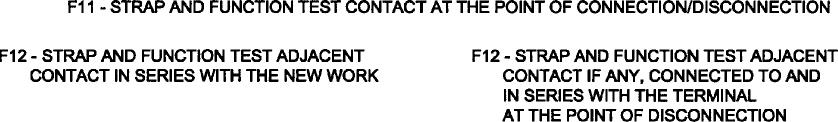
17 contacts (not shown in that circuit order in the circuit diagrams) which might otherwise be inadvertently removed from circuit. 3.7 Testing the Altered Circuit The altered circuit comprises the new work, the contact, fuse or link at the point of connection and all parallel paths to the new work. When alterations to the circuit are complete, perform the following: i. a Wire Count and Null Count over the circuit alterations and on the top or base of all relays and equipment items that were to have wires connected or disconnected. (Compare against the alteration circuit diagrams and against the wire and null count recorded in accordance with Paragraph 3.2) ii. a Circuit Strap and Function Test over the alterations inclusive of the series contact, fuse or link adjacent to each side of the alteration iii. an apparatus function test to check trackside apparatus operation, adjustment and correspondence to indications and controls, if these are altered by the modifications iv. a function test to control tables of vital interlocking or controls, if these are altered by the modifications v. an operational test to check that the principal functions affected by the alteration are working. An accountable, senior, experienced signalling test engineer may approve deletion of the circuit strap and function test if the existing wiring is verified by hand tracing and an apparatus function test and function test to the control tables is to be performed in conjunction with the wire and null count. This engineer shall analyse the situation and satisfy himself/herself that all testing requirements to prove safety are covered. Details of the inspection and testing procedures for alterations to existing circuits are to be stipulated in the Detailed Inspection and Test Plan for New and Altered Works. 3.8 Certainty of Circuit Status If there is no certainty that the existing circuit is as shown in the circuit diagrams or if there is no certainty that tested new wiring etc., was fully secured against interference, intentional or inadvertent, then the inspection, testing and certification is to extend to the whole of the circuit containing the alterations. 3.9 Procedures for Modifications to Existing Circuits The following summary of the procedure is based on tracing the affected portion of the existing circuit rather than the alternative of strap and function testing the complete circuit after the modification. However the majority of the steps apply to both methods. March 2005 Page 17 of 23
18 3.9.1 Designers to check and approve the design of the whole of the circuit which is altered, (not just the modified portion) Wire count the complete circuit to be altered, against the circuit diagrams. (Unless otherwise approved) Record the number of wires on each and every terminal on the top, base or terminal assembly of every relay and equipment item where there will be a wiring change. Compare the null count with the circuit book analysis sheets At points of connection, trace and verify the existing wires connected to both sides of the existing contact, fuse or link at each point of connection of the alteration. At points of disconnection, trace and verify the existing wires connected to the terminal that is the point of disconnection. Verify the wire count at both ends of these existing wires. Label wires at ends next to points of connection and points of disconnection Further trace and verify to the circuit diagrams the existing wiring from contacts, fuses or links looped to each terminal which is a point of connection/ of the alteration. Verify wire count at both ends of these existing wires. Steps & shall include tracing existing wires from the point of connection to one series contact, fuse or link clear of the alteration and where applicable, to adjacent contacts in parallel with the contact at the point of connection Trace and verify to the circuit diagrams each and every existing wire that will become redundant in the altered circuit. Verify wire count at both ends of these existing wires. Label wires at both ends Trace and wire count to the circuit diagrams the circuit paths in parallel with the new circuit work Wire count, bell test, insulation test and strap and function test all contacts, fuses and links in the new circuit work Changeover to new circuitry Disconnect, cut back and remove each and every redundant wire, tracing it throughout Strap and function test the existing contact, fuse or link at each point of connection/disconnection. (If this contact, fuse of link is in parallel with the alteration then all the contacts, fuses and links in the alteration shall be open and any other parallel path shall also be opened for this test) Strap and function test the series contact, fuse or link, adjacent to March 2005 Page 18 of 23
19 each side of the new work (with all the contacts, fuses and links in the new work closed and with paths parallel to the alteration open). (In some cases this may be the existing contact, fuse or link at the point of connection covered in Step above). At points of disconnection, strap and function test the adjacent contact, fuse or link, if connected to and in series with the terminal at the point of disconnection Perform a wire count and null count over the circuit alterations and on the top, base or terminal assembly of all relays or equipment items that were to have wires connected or disconnected. Compare against the alteration circuit diagrams and the wire and null count recorded in accordance with Step above Perform an apparatus function test to check trackside apparatus operation, adjustment and correspondence to indications and controls, if these are altered by the modifications Perform a function test to control tables of vital interlocking or controls, if these are altered by the modifications Perform an operational test to check that the principal functions affected by the alteration are working Where both active and common legs (or positive and negative legs) of power supply or circuit wiring are affected, or where power supply components are affected, check to ensure polarity has not been reversed. Note: The point of connection/disconnection is the existing terminal to which a new wire connects or from which an existing wire is disconnected. Note: Where tracing is not practical a strap and function test is required of all contacts, fuses and links in the modified circuit which are connected to the ends of wires that were to be traced in the above procedure. Tracing of wires connecting to the terminal that is a point of connection/disconnection is still required as is tracing of all wires that become redundant. Note: The above procedure may contain some redundancy and any departure must be given proper consideration by accountable, senior experienced signalling testers and the procedures to be followed shall be documented and approved prior to the work. Note: If the evidence is that the existing circuit wiring diagrams are accurate and the local maintenance Signal Engineer and the Commissioning Engineer are so satisfied after proper investigation, then the above procedures may be unduly onerous where there are multiple paths in parallel with the alteration and/or where these paths are particularly long. In such cases consideration could be given to limiting the tracing of existing wires in Step 3.95 (T5) from the point of connection to adjacent contacts in just two parallel March 2005 Page 19 of 23
20 paths, and to limiting Step (T7) to a wire count of the contacts and links in the paths parallel to the alteration, deleting the requirement for hand tracing. Function tests would still be required. Conversely, if there is any lack of confidence in the information or there is scope for error in the process then test engineers shall give due consideration to more comprehensive testing than covered by the above procedure. Refer to Paragraph 'Modifications on a Large Scale'. REFER TO ILLUSTRATIONS ON THE FOLLOWING PAGES 3.10 Modifications on a Large Scale Where there are many and/or complex modifications to existing circuits the Tester in Charge and the Commissioning Engineer shall analyse the potential for error using risk analysis techniques similar to failure (error) mode effect and criticality analysis, task analysis, fault tree analysis. The probability of human error in performing multiple tasks increases with the number of repetitions and is influenced by the rigour and application of the testing methods, by the testers' experience, alertness, awareness of the potential sources or error, sense of accountability, state of fitness and whether the environment is favourable or adverse to the chances of an error free process. The Tester in Charge and the Commissioning Engineer shall consult with the local maintenance Signal Engineer or with other accountable, senior experienced signalling testers on the breadth, depth and detail of the inspection and testing required to ensure the integrity of the modified installation and these determinations shall be fully documented. Step by step procedures for critical activities shall also be fully documented and communicated to all staff concerned in the testing. These detailed procedures are to be included in the Inspection and Test Plan. March 2005 Page 20 of 23


21 March 2005 Page 21 of 23
22 March 2005 Page 22 of 23
23 March 2005 Page 23 of 23
Status Date Prepared Reviewed Endorsed Approved
 Discipline Engineering Standard NSW Category Signalling Title Introduction to Signalling Maintenance Procedures Reference Number SMP 01 (RIC Standard: SC 00 52 00 01 SI) Document Control Status Date Prepared
Status Date Prepared Reviewed Endorsed Approved
 Discipline Engineering Standard NSW Category Signalling Title Reference Number SMP 08 (RIC Standard: SC 00 52 00 08 SI) Document Control Status Date Prepared Reviewed Endorsed Approved Issue 1 Revision
Status Date Prepared Reviewed Endorsed Approved
 Discipline Engineering Standard NSW Category Signalling Title Rerailing Precautions to be Taken Reference Number SMP 26 (RIC Standard: SC 00 52 00 26 SI) Document Control Status Date Prepared Reviewed
Inspection and Testing of Signalling Inspection and Testing Principles
 Discipline: Engineering (Signalling) Category: Standard Inspection and Testing of Signalling Inspection and Testing Principles ESC-21-03 Applicability ARTC Network Wide CRIA (NSW CRN) Primary Source SCP
Reference Number PDS 10 (RIC Standard: EP SP)
") Discipline Engineering Standard NSW Category Electrical Title Reference Number PDS 10 (RIC Standard: EP 00 00 00 08 SP) Document Control Status Date Prepared Reviewed Endorsed Approved Mar 05 Standards
Discipline Engineering Standard NSW Category Electrical Title Reference Number PDS 10 (RIC Standard: EP 00 00 00 08 SP) Document Control Status Date Prepared Reviewed Endorsed Approved Mar 05 Standards
ELECTRICAL (COMPREHENSIVE) SAFETY PROGRAM REGULATORY STANDARD: OSHA - 29 CFR CFR , ,
 SAFETY PROGRAM REGULATORY STANDARD: OSHA - 29 CFR CFR , ,") ELECTRICAL (COMPREHENSIVE) SAFETY PROGRAM REGULATORY STANDARD: OSHA - 29 CFR 1910.331 335-29 CFR 1926.302, 1926.416, 1926.417 BASIS: The National Safety Council estimates that there are at least 300 deaths
ELECTRICAL (COMPREHENSIVE) SAFETY PROGRAM REGULATORY STANDARD: OSHA - 29 CFR 1910.331 335-29 CFR 1926.302, 1926.416, 1926.417 BASIS: The National Safety Council estimates that there are at least 300 deaths
PSSI 3 High Voltage Metal-Enclosed Switchgear
 1. SCOPE This Safety Instruction applies the principles established by the ScottishPower Safety Rules (Electrical and Mechanical) and Company Safety Instructions to achieve Safety from the System for personnel
PSSI 6 Demarcation of Work Areas in Substations
 1. SCOPE This Safety Instruction applies the principles established by the ScottishPower Safety Rules (Electrical and Mechanical), setting down the requirements in those situations where it is necessary
Low Voltage Electricity System Safety Rules & Associated Safety Guidance
 Annex J To Loughborough University Facilities Management (FM) Health and Safety Policy Low Voltage Electricity System Safety Rules & Associated Safety Guidance 1. Introduction a. These Safety Rules are
SAFETY QUALITY TECHNOLOGY. Guidance on Safe Isolation Procedures
 SAFETY QUALITY TECHNOLOGY Guidance on Safe Isolation Procedures Introduction Every year, people working on construction sites suffer electric shock and burn injuries some of which, tragically, are fatal.
C&G 2395 Exam Paper April Section A - All questions carry equal marks. Answer all three questions. Show all calculations.
 C&G 2395 Exam Paper April 2013 Section A - All questions carry equal marks. Answer all three questions. Show all calculations. Q.1 The electrical installation in a small food retail outlet is scheduled
C&G Level 3 Award in the Periodic Inspection, Testing and Certification of Electrical Installations
 C&G 2395-01 Level 3 Award in the Periodic Inspection, Testing and Certification of Electrical Installations Test instruments and recommended testing sequence 1 Outcomes of this Session describe the different
OPERATING CODE NO. 8 APPENDIX 2
 OPERATING CODE NO. 8 APPENDIX 2 (OC8B) SAFETY CO-ORDINATION IN RESPECT OF THE SCOTTISH TRANSMISSION SYSTEMS OR THE SYSTEMS OF SCOTTISH USERS Paragraph No/Title CONTENTS (This contents page does not form
Electrical Shore Connections
 RULES FOR CLASSIFICATION OF Ships / High Speed, Light Craft and Naval Surface Craft PART 6 CHAPTER 29 NEWBUILDINGS SPECIAL EQUIPMENT AND SYSTEMS ADDITIONAL CLASS Electrical Shore Connections JULY 2014
The definition of a competent person given in the Electricity at Work Regulations 1989 (EWR) is as follows:
 is as follows:") Electrical Safety Guidance Note 1 - General Guidance Competent Person The definition of a competent person given in the Electricity at Work Regulations 1989 (EWR) is as follows: "A person in the possession
Electrical Safety Guidance Note 1 - General Guidance Competent Person The definition of a competent person given in the Electricity at Work Regulations 1989 (EWR) is as follows: "A person in the possession
ES18 Security Theory/Regulations Answer Schedule
 ES18 Security Theory/Regulations Answer Schedule Notes:1. means that the preceding statement/answer earns 1 mark. 2. This schedule sets out the expected answers to the examination questions. The marker
Rigel 601 CHECKBOX. Instruction Manual. 348A551 Issue 2.0. April Seaward Electronic Ltd. Issue 2.0
 Rigel 601 CHECKBOX Instruction Manual 348A551 Issue 2.0 April 2006 2006 Seaward Electronic Ltd. Issue 2.0 Limited Warranty & Limitation of Liability Rigel Medical guarantees this product for a period of
Operating Instructions
 Operating Instructions Light-metal Ex d enclosures / flameproof enclosure > 8265/0 Empty enclosure > 8265/4 Control panel, integrated in Ex e enclosure > 8265/5 Control panel Table of Contents 1 Table
General maintenance engineering applications
 Unit 068 General maintenance engineering applications Level: 2 Credit value: 12 NDAQ number: 500/9514/6 Unit aim This unit covers the skills and knowledge needed to prove the competences required to cover
Ventam 85 Installation & Commissioning Instructions
 Ventam Systems Ltd Unit D4 Seedbed Business Centre Vanguard Way Shoeburyness Essex SS3 9QY Phone 01702 382 307 Fax 01702 382 340 Ventam 85 Installation & Commissioning Instructions 1 General The Ventam
General maintenance engineering applications
 Unit 868 General maintenance engineering applications UAN: J/600/6007 Level: Level 2 Credit value: 12 GLH: 55 Relationship to NOS: Endorsement by a sector or regulatory body: Aim: This unit has been derived
PECIMEN IMM6. Minor Electrical Installation Works Certificates. Amd 3: In accordance with BS 7671
 IMM6 NCR (No Carb o n Requi red) Minor Electrical Installation Works Certificates Installer s Reference Number IRN/ PART 1: DETAILS OF THE MINOR WORKS Client: minor works completed: IMM6/ MINOR ELECTRICAL
! Warning, refer to accompanying documents.
 About this Manual To the best of our knowledge and at the time written, the information contained in this document is technically correct and the procedures accurate and adequate to operate this instrument
Issue 3. Module TS11. Failure of, or work on, signalling equipment signallers regulations. GERT8000-TS11 Rule Book
 Uncontrolled when printed GERT8000-TS11 Rule Book Failure of, or work on, signalling equipment signallers s Module TS11 Issue 3 September 2017 Comes into force 02 December 2017 Conventions used in the
E2K-L. Liquid Level Sensor That Is Unaffected by the Color of the Pipe or Liquid. Liquid Level Sensor. Ordering Information
 Liquid Level EK-L CSM_EK-L_DS_E 3 Liquid Level That Is Unaffected by the Color of the or Liquid Mount to bypass pipes. Fit a wide range of pipe diameters: 8 to mm or to mm Built-in Amplifiers to save space.
PSSI 1 High Voltage Switching
 1. SCOPE This Safety Instruction sets down the procedures to be adopted when carrying out High Voltage (HV) Switching operations on The Company s System and other System(s) operated by the Company other
QPEO2/037N Credit Value: 15 QCF Level: 2 GLH: 68 Maintaining electrical equipment/systems
 Performing Engineering Operations QPEO2/037N Credit Value: 15 QCF Level: 2 GLH: 68 Maintaining electrical equipment/systems Learner Name: 2013 Excellence, Achievement & Learning Ltd EAL Assessment Route
National Grid UK Electricity Transmission plc. NATIONAL SAFETY INSTRUCTION and Guidance
 National Grid UK Electricity Transmission plc NATIONAL SAFETY INSTRUCTION and Guidance LOW VOLTAGE EQUIPMENT Copyright National Grid plc 2016, all rights reserved. No part of this publication may be reproduced,
NZQA expiring unit standard version 6 Page 1 of 5. Demonstrate knowledge of electrical safety and safe working practices for electrical workers
 Page 1 of 5 Title Demonstrate knowledge of electrical safety and safe working practices for electrical workers Level 2 Credits 3 Purpose This unit standard is designed to meet the requirements of firsttime
Operating Instructions
 Operating Instructions Ex d Enclosures in Light Metal / Flameproof Encapsulation > 8265/0 Empty Enclosure > 8265/4 controller, installed in Ex e enclosure > 8265/5 controller Contents 1 Contents 1 Contents...2
C&G 2395 Exam Paper June Section A-All questions carry equal marks. Answer all three questions. Show all calculations.
 C&G 2395 Exam Paper June 2013 Section A-All questions carry equal marks. Answer all three questions. Show all calculations. 1. The electrical installation in an industrial unit is scheduled for a periodic
HSE guidelines. SMay 2015 ELECTRICAL SAFETY HSE LIFE THE NATIONAL OIL&GAS INDUSTRY STANDARD FOR PROFESSIONALS
 HSE guidelines SMay 2015 ELECTRICAL SAFETY HSE LIFE THE NATIONAL OIL&GAS INDUSTRY STANDARD FOR PROFESSIONALS Work safely or do not work at all There are strict procedures when working on electrical installations
E2.14 Control of Hazardous Energy. Effective Date: 03/01/2018
 University Policy Volume E2: Environment, Health, Safety and Security E2.14 Control of Hazardous Energy Responsible Office: Facilities Management Responsible Officer: Safety Officer POLICY STATEMENT All
PROCEDURES FOR STANDBY
 1 SCOPE This Procedure details both the circumstances in which standby shall be provided and the responsibilities borne by the Standby Man in such circumstances. 2 ISSUE RECORD This is a maintained/controlled
Ground Fault Circuit Interrupter(GFCI) Policy
 Policy") NewStar Netronics, LLC American Products for the World Ground Fault Circuit Interrupter(GFCI) Policy 3926 East 3 rd Street Tulsa, OK 74112 Phone (918)894-5006 Fax (918)836-9909 tech@newstarnetronics.com
NewStar Netronics, LLC American Products for the World Ground Fault Circuit Interrupter(GFCI) Policy 3926 East 3 rd Street Tulsa, OK 74112 Phone (918)894-5006 Fax (918)836-9909 tech@newstarnetronics.com
RULES FOR CLASSIFICATION Naval vessels. Part 1 Classification and surveys Chapter 5 Surveys for submarines. Edition January 2016 DNV GL AS
 RULES FOR CLASSIFICATION Naval vessels Edition January 2016 Part 1 Classification and surveys Chapter 5 The content of this service document is the subject of intellectual property rights reserved by ("DNV
Inspection and Testing
 Chapter 16 Inspection and Testing 16.1 INTRODUCTION The Purpose of Inspection, Testing and Certification or Reporting The fundamental reason for inspecting and testing an electrical installation is to
SEMEEE3-34 Carrying out functional tests on electrical equipment
 Overview This standard identifies the competences you need to carry out functional tests on electrical equipment, in accordance with approved procedures. You will be required to carry out pre-test inspections
USER MANUAL. JET TST and JET TST S.
 USER MANUAL JET TST and JET TST S www.sisteven.com Types of Jet fans: JET TST UNI: Impulse axial fan single direction JET TST S UNI: Impulse axial fan single direction (short case) JET TST REV: Impulse
SEMEMI SQA Unit Code H2AP 04 Carrying out fault location on electrical equipment and circuits
 Carrying out fault location on electrical equipment and circuits Overview This unit identifies the competences you need to locate faults on electrical equipment and circuits, in accordance with approved
CCSSL35 Carry out the wiring and testing of electrical circuits and equipment
 Carry out the wiring and testing of electrical circuits and equipment Overview This standard is about the basic competences that you need to wire up and test electrical equipment and circuits for the theatre
MANUAL DIRECT PURGE OPTION. UNION Instruments GmbH CWD2005 PLUS. General information, safety standards and regulations for direct purge option
 MANUAL DIRECT PURGE OPTION UNION Instruments GmbH CWD2005 PLUS General information, safety standards and regulations for direct purge option Version: V1.00 Stand: 24.03.2010 Union Instruments GmbH Zeppelinstr.
Gas Network Craftsperson
 Gas Network Craftsperson Unit EIAU016 Carrying out Fault Diagnosis on Electrical Equipment and Circuits This assessment specification has been developed as part of the network maintenance craftsperson
Aligning EDIS with Guidance Note 3
 EDIS USER GUIDE Aligning EDIS with Guidance Note 3 Using EDIS to adhere to Guidance Note 3: Inspection & Testing (Electrical Regulations), incorporating amendment 3 2015 Doc Version: 27 Feb 2017 www.electricalcertificates.co.uk
Pressure Systems Safety Regulation
 Pressure Systems Safety Regulation Introduction This document informs Faculty of the key requirements of the UK and Chinese Pressure Systems Safety regulations. The aim of these regulations is to prevent
Electrical Safety Work Practices
 Work Practices I. SCOPE This program covers any SOUTHWESTERN COMMUNITY COLLEGE employee that may work or be exposed to exposed electrical systems: To assure that employees are not exposed to potentially
SEMME2135 Assisting in modifying and adding electrical circuits in yachts and boats
 Assisting in modifying and adding electrical circuits in yachts and boats Overview This standard identifies the competences you need to assist with the modification or addition of electrical circuits in
Purpose. Scope. Process flow OPERATING PROCEDURE 07: HAZARD LOG MANAGEMENT
 SYDNEY TRAINS SAFETY MANAGEMENT SYSTEM OPERATING PROCEDURE 07: HAZARD LOG MANAGEMENT Purpose Scope Process flow This operating procedure supports SMS-07-SP-3067 Manage Safety Change and establishes the
Sinorix MANOB480, MANOCAB, MANOEOL Installation Maintenance
 Sinorix MANOB480, MANOCAB, MANOEOL Installation Maintenance Building Technologies 2017-10-24 Control Products and Systems Legal notice Legal notice The specifications and availability are subject to change
Maintaining electrical equipment/systems
 Unit 037 Maintaining electrical equipment/systems Level: 2 Credit value: 15 NDAQ number: 500/9514/6 Unit aim This unit covers the skills and knowledge needed to prove the competences required to cover
SG33KTL-M Quick Installation Guide. 1 Unpacking and Inspection
 SG33KTL-M Quick Installation Guide This guide provides a general instruction of the installation procedures of SG33KTL-M. In no case shall this guide substitute for the user manual or related notes on
Construction & Building Industry Safety Guideline. Electrical Isolations
 Construction & Building Industry Safety Guideline Electrical Isolations Disclaimer This Guideline contains information regarding work health and safety. It includes some of your obligations under the work
Trackside Warning Signs and Markings
 Discipline: Engineering (Track & Civil) Category: Standard Trackside Warning Signs and Markings ETM-11-01 Applicability New South Wales CRIA (NSW CRN) Primary Source ARTC Standards BDS 19, RDS 03 and ESS
CALIBRATION SYSTEM REQUIREMENTS. ESCC Basic Specification No
 Page 1 of 8 CALIBRATION SYSTEM REQUIREMENTS ESCC Basic Specification Issue 4 February 2014 Document Custodian: European Space Agency see https://escies.org PAGE 2 LEGAL DISCLAIMER AND COPYRIGHT European
Football Lighting Policy & Requirements Season 2016
 Football Lighting Policy & Requirements Season 2016 The Football Lighting Policy & Requirements (the Policy) sets out the mandatory requirements for competition lighting at football (soccer) venues used
SAFETY DIRECTIVE 2.0 DEPARTMENTS AFFECTED. This Administrative Directive shall apply to all Town of Marana departments and employees.
 SAFETY DIRECTIVE Title: Control of Hazardous Energy Lock-out/Tag-out/Try-out Issuing Department: Town Manager s Safety Office Effective Date: July 1, 2014 Approved: Gilbert Davidson, Town Manager Type
Isolation Standard - Tags
 Isolation Standard - Tags 1. Purpose To provide Nyrstar Hobart with a procedure designed to ensure anyone working on plant and equipment is kept free from injury or incidents resulting from uncontrolled
To Loughborough University (LU) Facilities Management (FM) Health and Safety Policy
 Facilities Management (FM) Health and Safety Policy") Annex I To Loughborough University (LU) Facilities Management (FM) Health and Safety Policy High Voltage (HV) Electricity System Safety Rules and Associated Safety Guidance 1. Introduction a. These Safety
Annex I To Loughborough University (LU) Facilities Management (FM) Health and Safety Policy High Voltage (HV) Electricity System Safety Rules and Associated Safety Guidance 1. Introduction a. These Safety
Document Control Summary Status: Replacement for Electricity High Voltage SOP v1.0 Version: V1.1 Date: July 2017 Author/Title: Owner/Title:
 Corporate Electricity High Voltage SOP Document Control Summary Status: Replacement for Electricity High Voltage SOP v1.0 Version: V1.1 Date: July 2017 Author/Title: Owner/Title: John Biggs/Estates Officer
General Accreditation Guidance. User checks and maintenance of laboratory balances
 General Accreditation Guidance User checks and maintenance of laboratory balances January 2018 Copyright National Association of Testing Authorities, Australia 2010 All intellectual property rights in
Original Date of Issue: 04/09
 POLICIES AND PROCEDURES DEPARTMENT: Environmental Health and Safety SUBJECT: Electrical Safety Program Original Date of Issue: 04/09 Reviewed 12/2011 Revised 12/2011 BACKGROUND ELECTRIC SHOCK It is well
Operating Instructions for BAIR22-6 AIR-POWERED CRIMPING TOOL
 Operating Instructions for BAIR22-6 AIR-POWERED CRIMPING TOOL Read and understand all of the instructions and safety information in this manual before operating or servicing this tool. Table of Contents
Covered Task 409OP Training Guide Inspecting Interference Bonds
 Directions This training guide is to be used by a Subject matter expert (SME) authorized Evaluator/Trainer and Trainee during on-thejob training (OJT) or prior to an evaluation as a resource. (S) Indicates
List all key terms and acronyms used in the procedure, and their definitions.
 Purpose The purpose of this procedure is to provide guidelines for electrical safety in general within Seqwater in compliance with the Electrical Safety Act 2002, Industry Codes of Practice, Regulations,
 1 2 CONTENTS INTRODUCTION Owner Information 4 Warranty Registration 5 Safety Instructions Safety 6 Safety Decals 7 Safety Identification Labels 8 Safety Notice 10 Safety Standards 11 Risk Assessment 13
INSPECTION, TESTING AND CERTIFICATION OF GASFITTING WORK DONE UNDER SUPERVISION
 ISSN 1172-3416 NZ GCP 1 : 1993 NEW ZEALAND GAS CODE OF PRACTICE for INSPECTION, TESTING AND CERTIFICATION OF GASFITTING WORK DONE UNDER SUPERVISION Issued by the Secretary of Commerce in accordance with
LOCK-OUT/TAG-OUT (LO/TO) SAFETY PROGRAM
 SAFETY PROGRAM") LOCK-OUT/TAG-OUT (LO/TO) SAFETY PROGRAM REGULATORY STANDARD: OSHA - 29 CFR 1910.147 BASIS: Approximately three million workers in the United States face risks from uncontrolled energy when servicing machinery
LOCK-OUT/TAG-OUT (LO/TO) SAFETY PROGRAM REGULATORY STANDARD: OSHA - 29 CFR 1910.147 BASIS: Approximately three million workers in the United States face risks from uncontrolled energy when servicing machinery
ISOLATION ISSUE 2 1 AIM 2 4 REASONS FOR INCLUSION 3 6 PLANT AND EQUIPMENT REQUIREMENTS 3 7 SYSTEM & PROCEDURAL REQUIREMENTS 4 8 PEOPLE REQUIREMENTS 6
 CONTENTS PAGE 1 AIM 2 2 APPLICATION 2 3 DEFINITIONS 2 4 REASONS FOR INCLUSION 3 5 REQUIREMENTS 3 6 PLANT AND EQUIPMENT REQUIREMENTS 3 7 SYSTEM & PROCEDURAL REQUIREMENTS 4 8 PEOPLE REQUIREMENTS 6 APPENDIX
Management Plan for Electrical Safety ISD #535
 Management Plan for Electrical Safety ISD #535 Health & Safety Office Maintenance Service Building 10 SE 9 ½ Street Rochester, MN 55904 507-328-4507 MANAGEMENT PLAN FOR ELECTRICAL SAFETY Table of Contents
Electrical Safety in the Food Industry
 Health and and Safety Executive Electrical Safety in the Food Industry John Chamberlain HM Principal Specialist Inspector (Electrical & Control Systems) Manchester CROWN COPYRIGHT What I ll cover Legal
SG36KTL-M Quick Installation Guide. 1 Unpacking and Inspection
 SG36KTL-M Quick Installation Guide This guide provides a general instruction of the installation procedures of SG36KTL-M. In no case shall this guide substitute for the user manual or related notes on
PULSAR 5000 SERIES OPERATING & INSTALLATION INSTRUCTIONS SERIES 5000 PLEASE READ CAREFULLY BEFORE INSTALLING
 PULSAR 5000 SERIES OPERATING & INSTALLATION INSTRUCTIONS SERIES 5000 PLEASE READ CAREFULLY BEFORE INSTALLING Please Note: Ranges above 500mbar are designed and manufactured in accordance with sound engineering
Common Discrepancies Uncovered on ADCI Diving Contractor & Training Program Audits
 Common Discrepancies Uncovered on ADCI Diving Contractor & Training Program Audits Ways to Set Your Company or School Up For Success on ADCI Audits and Reduce Costs In most instances, all discrepancies
User s Guide Temperature Sensor Converter TSC-599
 User s Guide Temperature Sensor Converter TSC-599 ILX Lightwave Corporation 31950 Frontage Road Bozeman, MT, U.S.A. 59715 U.S. & Canada: 1-800-459-9459 International Inquiries: 406-556-2481 Fax 406-586-9405
12V MINI AIR COMPRESSOR
 12V MINI AIR COMPRESSOR STOCK No.65958 PART No.DA12/250A INSTRUCTIONS IMPORTANT: PLEASE READ THESE INSTRUCTIONS CAREFULLY TO ENSURE THE SAFE AND EFFECTIVE USE OF THIS TOOL. 08/2001 GENERAL INFORMATION
WORLDSKILLS SINGAPORE 2018 TECHNICAL DESCRIPTION
 Recommended Entry Requirements 1. Possess technical skills and knowledge in electrical, mechanical and pneumatic installation at National ITE Certificate (Nitec) level and above 2. Must undergo and complete
COOPER POWER SERIES. D-73P3 bypass switches installation instructions. Switches MN008005EN. Effective April 2016 Supersedes S June 2013
 Switches MN008005EN Effective April 2016 Supersedes S328-120-1 June 2013 D-73P3 bypass switches installation instructions COOPER POWER SERIES DISCLAIMER OF WARRANTIES AND LIMITATION OF LIABILITY The information,
Guidance on Mounting Cameras on Sailplanes and Powered Sailplanes, AIRW-D024 INTRODUCTION SCOPE
 INTRODUCTION For a number of years pilots have fitted small cameras to sailplanes in Australia as evident by the many You Tube videos. These cameras have been installed by the pilots with no guidance or
Portable Appliance Testing
 The University of Edinburgh E Brief description of the paper University Health and Safety Committee Tuesday 18 th November 2014 Portable Appliance Testing This Paper presents the review of the University
Indicators and Signs ANSG 604. Applicability NSW SMS. Publication Requirement. External Only. Document Status September 2018.
 Applicability NSW SMS Publication Requirement External Only Document Status Issue/Revision # Effective from 5.1 16 September 2018 Australian Rail Track Corporation Limited (ARTC) Disclaimer This document
Defective Fixed Signals - Rules 1 to 6
 Defective Fixed Signals - Rules 1 to 6 Applicability VIC Publication Requirement External Only Document Status Issue/Revision # Effective from 1 07 August 201 0 04 October 2015 Australian Rail Track Corporation
SIL Safety Manual. ULTRAMAT 6 Gas Analyzer for the Determination of IR-Absorbing Gases. Supplement to instruction manual ULTRAMAT 6 and OXYMAT 6
 ULTRAMAT 6 Gas Analyzer for the Determination of IR-Absorbing Gases SIL Safety Manual Supplement to instruction manual ULTRAMAT 6 and OXYMAT 6 ULTRAMAT 6F 7MB2111, 7MB2117, 7MB2112, 7MB2118 ULTRAMAT 6E
ELECTRIC OPERATING PROCEDURES Date: 11/01/06
 Doc No.: NG-USA EOP D001 Page: 1 of 5 ELECTRIC OPERATING PROCEDURES SUBJECT: Cutouts Open/Enclosed Type SECTION: Distribution/Overhead REFERENCE: National Grid Retail Company Safety Manuals National Grid
Advances in Low Voltage Motor Control Center (MCC) Technology Help Reduce Arc-Flash Hazards and Minimize Risks
 Technology Help Reduce Arc-Flash Hazards and Minimize Risks") Advances in Low Voltage Motor Control Center (MCC) Technology Help Reduce Arc-Flash Hazards and Minimize Risks Selecting the right MCC equipment leads to improved plant safety, helping protect people and
Advances in Low Voltage Motor Control Center (MCC) Technology Help Reduce Arc-Flash Hazards and Minimize Risks Selecting the right MCC equipment leads to improved plant safety, helping protect people and
LOCKOUT/TAGOUT PROGRAM
 Santa Clarita Community College District LOCKOUT/TAGOUT PROGRAM Revised March 2018 TABLE OF CONTENTS PURPOSE... 3 COMPLIANCE...4 DEFINITIONS...5 SECTION I - ENERGY CONTROL PROCEDURES... 7 SECTION II -
Inspection Recommendations
 S&C Vista SD Underground Distribution Switchgear Pad-Mounted and Vault-Mounted Styles Outdoor Distribution (17.5 kv and 29 kv) With Visi-Gap Load Interrupter Switches and Visi-Gap Fault Inetrrupters Inspection
SEMEM3-65 Servicing anaesthetic and ventilation equipment
 Overview This unit identifies the competences you need to carry out servicing activities on anaesthetic and ventilation equipment, in accordance with approved procedures. You will be required to service
ARKANSAS TECH UNIVERSITY FACILITIES MANAGEMENT HEALTH AND SAFETY MANUAL (LOCKOUT/TAGOUT) 30.0
 30.0") () 30.0 The purpose of the Energy Control Policy (Lockout/Tagout) is to ensure that before any employee performs any servicing and/or maintenance on machinery or equipment, where the unexpected energizing,
() 30.0 The purpose of the Energy Control Policy (Lockout/Tagout) is to ensure that before any employee performs any servicing and/or maintenance on machinery or equipment, where the unexpected energizing,
PERIODIC INSPECTION REPORT FOR AN ELECTRICAL INSTALLATION
 For explanatory notes relating to software endorsement, see Notes for Recipients A. DETAILS OF THE CLIENT Client: PERIODIC INSPECTION REPORT FOR AN ELECTRICAL INSTALLATION Issued in accordance with British
These Electricity Safety Rules and associated National Safety Instructions are written to safeguard personnel working for or on behalf of National
 These Electricity Safety Rules and associated National Safety Instructions are written to safeguard personnel working for or on behalf of National Grid, on or near to its electricity apparatus. National
SUP 15 Health & Safety Management Pressure Systems. Unified procedures for use within NHS Scotland
 SUP 15 Health & Safety Management Pressure Systems Unified procedures for use within NHS Scotland September 2015 Contents Page Acknowledgements... 3 1. Introduction... 4 2. Purpose of this Procedure...
We agree the CGA publication more adequately reflects the equipment accuracy requirements for performing a pressure test on cylinders.
 Comments regarding NPRM of 49 CFR parts 171 & 180 Page 1 of 11 Proposed 180.205(g): I believe the proposed incorporation by reference of CGA C-1 into 180.205 would be a mistake and a step backwards in
TECHNICAL SPECIFICATION
 TECHNICAL SPECIFICATION IEC TS 61245 Edition 2.0 2015-03 Artificial pollution tests on high-voltage ceramic and glass insulators to be used on d.c. systems INTERNATIONAL ELECTROTECHNICAL COMMISSION ICS
WORKPLACE SAFETY AND HEALTH ACT (CHAPTER 354A) WORKPLACE SAFETY AND HEALTH (CONFINED SPACES) REGULATIONS 2009
 WORKPLACE SAFETY AND HEALTH (CONFINED SPACES) REGULATIONS 2009") WORKPLACE SAFETY AND HEALTH ACT (CHAPTER 354A) WORKPLACE SAFETY AND HEALTH (CONFINED SPACES) REGULATIONS 2009 In exercise of the powers conferred by section 65 of the Workplace Safety and Health Act, the
WORKPLACE SAFETY AND HEALTH ACT (CHAPTER 354A) WORKPLACE SAFETY AND HEALTH (CONFINED SPACES) REGULATIONS 2009 In exercise of the powers conferred by section 65 of the Workplace Safety and Health Act, the
Lock Out - Tag Out Safety Program
 Lock Out - Tag Out Safety Program Daniel Schmid 4-22-15 Pam Schmid 4-22-15 Dan Schmid Pam Schmid Safety Director Quality Director Table of Contents DOCUMENT REVISION TABLE... 3 PURPOSE... 4 RESPONSIBILITY...
12V Mini Air Compressor
 INSTRUCTIONS FOR 12V Mini Air Compressor Stock No.80999 Part No.DA12/250B IMPORTANT: PLEASE READ THESE INSTRUCTIONS CAREFULLY TO ENSURE THE SAFE AND EFFECTIVE USE OF THIS PRODUCT. GENERAL INFORMATION This
KMW3000C. User Manual. Water Chiller for Xcalibur and Gemini systems. Version 1.6, September 2010
 KMW3000C Water Chiller for Xcalibur and Gemini systems User Manual Version 1.6, September 2010 Agilent Technologies XRD Products 10 Mead Road, Yarnton, Oxfordshire. OX5 1QU, UK Tel: +44 (0)1865 291600
Overview. SEMEMI211 SQA Unit Code HF4E 04 Carrying out modifications or rewiring electrical circuits
 Overview This standard identifies the competences you need to modify or rewire electrical circuits and equipment, in accordance with approved procedures. This will involve modifying or rewiring electrical
Health & Safety Policy & Plan. Rightway Roofing.
 Health & Safety Policy & Plan. Rightway Roofing. Valid: 02/2012-02/2013 Contents ( 1 ) Policy Statement. ( 2 ) Hazard Identification. ( 3 ) Hazard Management. ( 4 ) Induction & Training. ( 5 ) Monitoring
: Electric Power Generation, Transmission, and Distribution. Region IV - OSHA
 1910.269: Electric Power Generation, Transmission, and Distribution Region IV - OSHA Scope This standard covers the operation and maintenance of electric power generation, control, transformation transmission,