INSTALLATION, OPERATION AND MAINTENANCE HANDBOOK
|
|
|
- Brittney McBride
- 5 years ago
- Views:
Transcription

1 INSTALLATION, OPERATION AND MAINTENANCE HANDBOOK XLC 430 FLOW CONTROL VALVE
2 INSTALLATION, OPERATION AND MAINTENANCE HANDBOOK Model XLC 430 This handbook provides information about the installation, operation and maintenance of the float rate control valves. XLC 430 is an automatic valve that prevents an excessive flow rate by reducing it to a value already stabilised, independent of the upstream pressure. The valve is operating by the pressurized fluid of the line and controlled by a 2 ways adjustable pilot, spring loaded, and preset to a differential pressure created through a flanged orifice installed downstream of the valve. Also every variations of the pressure is immediately sensed by the pilot which sends a command to the main valve. Installation 1) Make sure that the pit is wide enough and easily accessible in order to carry out the maintenance operations and to allow the control of the pressure gauges and the position indicator; moreover it has to be equipped with a drainage for the cleaning of the filter. 2) Install upstream and downstream two gate valves in order to allow the maintenance and install always a filter upstream of the valve (See picture on the next page). 3) Before installing the valve, proceed to an accurate cleaning of the pipes and conducts in contact with the apparatus itself in order to avoid that impurities like earth, stones, pebbles and yard material can ruin the inner seats clogging the circuit pilot. 4) Place the valve according to the direction of the arrow cast on the body. 5) We suggest to install the valve in horizontal position in order to obtain the maximum efficiency and to avoid wear phenomena of the parts although up to DN 125 it is also possible to install it in vertical position. 6) Do never raise the valve through the circuit pilot but only use the eyebolts or flanges; before operating the valve make sure that there are no damages to the circuit of pilot, to the relative fittings or to the position indicator. 7) In particular cases, the difference of pressure between upstream and downstream causes a thrust that must be faced with an adequate block of anchorage. 8) If not already included in the order we strongly recommend to install a pressure gauge downstream of the valve in one of the outlets. 9) The valve is supplied with a flanged orifice, provided with the pressure outlet on the downstream side to allow for the connection with the pilot s cover. This flange has to be installed with the stainless steel disk on the upstream part and at least downstream of the main valve at a distance of 5 DN of the XLC, this is to avoid disturbances on the signal addressed to the pilot.
3 Set up instructions Before setting up the valve make sure that all the pressure gauges ( if included in the order) have been placed and that the position indicator is properly installed, and make sure that the safety of persons and systems are guaranteed. Operate very slowly to avoid water hammer effects and wait as long as necessary, after each operation, so that the valve is able to react and reach a balance. 1 - Open slowly the upstream gate valve while the downstream gate valve remains closed. 2 - Make sure that the adjustable valves to regulate the opening, closing speed and reaction time of the GRIFO are opened. 3 - Eliminate the air trapped inside the circuit of the main valve by means of the air valve placed at the top of the position indicator, and loose the fittings of the circuit at the higher points. After these operations, which must be done in an accurate and careful way, retighten everything firmly. 4 - Control that the connection between the pilot and the flanged orifice are operating properly and discharge all the air from the upper fitting. 5 - Open slowly the downstream gate valve and turn the screw of the pilot clockwise to raise the flow rate, or counter-clockwise to decrease it. The regulation has to be made under pressure, which means working very slowly and after each sequence wait for the system to get stabilized. Pilot circuit Including: a) 3 ball valves 3/8 PN 40 in nickel brass that must be opened during the valve operation. b) GR.I.F.O. unit control device containing a fine mesh filter in stainless steel, one valve to regulate the reaction time and two other trimmers of the speed for both the opening and closing phases. c) Pilot differential range MICROSTAB flow rate. d) Fittings in brass and pipes in stainless steel. e) Flange with a adjusted diaphragm and pressure outlet. Maintenance - The valve and circuit do not require a particular maintenance but it is necessary to plan periodic inspections, at least once a year which can be carried out without removing the valve from the conduct, in order to check the pilot circuit and clean the filter of the GRIFO control device. - Just in case you had to order spare parts, please refer to the serial number engraved on the metallic label applied on the upper surface of the GRIFO. - Instructions for maintenance of the pilot and the main valve are described more in details in the following sections, shouldn t that be enough please contact immediately CSA Srl, Strada S. Giuseppe, 15 - Salsomaggiore Terme(PR) tel Fax info@csasrl.it
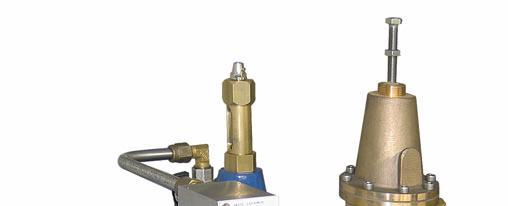
4 MLP FLOW CONTROL PILOT These are the compression force of the spring called F, and the pressure taken after the flanged orifice called B directly connected to the pilot s cover. These forces are perfectly balanced against the downstream pressure called A exerted on the lower part of the main valve s downstream pressure outlet. F+B=A. When the flow rate increases through the adjusted diaphragm, the head loss will increase and will lower the value of B with the result that the sum of F+B will be below A. The pressure A will lift the diaphragm and the obturator to which it is connected, closing the passage just enough to make the main valve close. When the flow rate decreases, the pressure B raises which causes the pilot and the main valve to open. The regulation of the flow rate value is made by turning the upper screw, placed on the cover, with a screwdriver in order to adjust the hydraulic grade line from the spring to the diaphragm. By turning the screw clockwise the flow rate increases and by turning it anti-clockwise it decreases. After the pressure regulation it is necessary to block the lock nut and to replace the protection cap. Disassembly It is not necessary to remove the pilot from the circuit for the disassembly. Use instead the enclosed picture which indicates the numbers specified here below performing the operations. 1- Remove the cap (4) loosen the tightening nut (36) and turn the lead screw (21) anti-clockwise until the spring is completely unloaded. 2- Remove the screws (19) while holding the cover of the pilots (20). 3- Separate the cover, the spring (35) and the spring guide (7). 4- Remove the lower tap (16) together with the gasket (17). 5- Remove the gasket holder (14) with a tube key while controlling the gasket for damages and replace it if necessary. 6- Remove the tightening nut (12), the upper disk (10) and the diaphragm (11). 7- Check the diaphragm for possible damages and replace in case of damages. 8- Check the sealing seat (13) and if necessary remove it by using a tube key. Inspection and repair During these operations check carefully every detail for possible damages, in particular the diaphragm and the sealing seat gasket. The pilot is very sturdy and the materials are of high quality and designed to guarantee many years of working conditions for which, generally, it is sufficient to remove the deposits and make sure to keep the metallic components properly lubricated. Shouldn t that be enough we strongly recommend you to contact CSA technical support or to order the maintenance kit. The flow regulating pilot is a diaphragm valve, spring loaded and direct acting, which can basically be installed in any position. The functioning is to control and reduce the flow rate, by keeping it constant independent of sudden pressure changes. Operation The valve is normally opened as a result of two forces acting on the diaphragm itself. Reassembly To reassembly the pilot you will have to repeat, obviously in inverse sequence, the same steps specified in the dismantling phase, while paying attention to: - place first the diaphragm on the staple shaped gasket holder, then the upper flat and the self-locking dice in order to fit the holes of the diaphragm with the holes on the pilots body. During this operation pay particular attention to the correct alignment of the staple shaped gasket holder with the protuberance of the body in order to avoid contacts and frictions that could affect the good operation of the pilot. To guarantee this operation bend the diaphragm so that the two holes matches on one side the staple shaped and tighten the dice. Insert this component in the body and with a light pressure screw the obturator on the staple shaped gasket holder and proceed with the cap provided with an o-ring so that the obturator can slide inside of it. Place the spring, the sealing seat, the cover, set the screws and put the cap back.
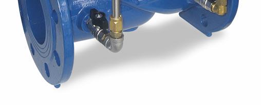
5 GRIFO 3/8 - PN 25 The GR.I.F.O. (Integrated Group Filter Orifices) is a control devices that includes all the functions necessary to the regulation of the main valve and its small dimensions lighten the pilot circuit and make it more useful, compact and intuitive. It is completely manufactured in stainless steel and contains : - a fine mesh filter in AISI 316 (8) to protect the pilot circuit from possible dirt, maintained simply by unscrewing the tap (9). - the intervention speed regulator* (4) of the main valve that allows ranging on a scale from 0 to 6, to modify the surface of the calibrated orifice. - the opening (3) and closing (2) speed regulators* of the valve s main chamber. - replaceable check valves placed upstream of every regulator and being able to limit the flow. - an upstream outlet not filtered protected by a cap 1/8 G - an upstream pressure outlet filtered, 1/8 G, protected by an air valve. - The calibration is normally done in factory although it is possible to modify it on the spot in order to search the optimal regulation according to the requested functions. The value 6 corresponds to the maximum passage surface of the fluid and therefore the maximum reaction speed, the value 0 to the total clogging. As indicated herewith enclosed the optimal values of calibration of the most common XLC applications POS. COMPONENT MATERIAL Body Closing speed control Opening speed control Reaction time control Check valve Not filtered pressure outlet 1/8G with tap Inlet 3/8G Filter Filter tap O-ring O-ring Filtered pressure outlet 1/8G with tap Cover Screws Poliacetale Brass AISI 316 NBR NBR Brass Plexiglass SS A2 REACTION TIME POSITION AND CORRESPONDENT DN POSITION Surface in mm 2 DN mm 0,5 1 1,5 2 2,5 3 3,5 4 4,5 5 5,5 6 0,76 2 3,2 4,4 5,6 6,8 8 9,25 10,4 11,7 12,9 13,7 1 1,6 2 2,4 2,7 3 3,2 3,4 3,6 3,8 4 4,2 Type Reaction speed Opening speed Closing speed XLC XLC XLC XLC Altre *The regulators are hollow valves designed and exclusive property of CSA Srl Maintenance The GRIFO is particular sturdy, extremely simple and reliable so it does not require maintenance but we strongly advise to proceed regularly with a clearing of the filter from dirt and deposits, simply by unscrewing the tap (9) and washing the mesh. It goes without saying that it would be advisable whatever is the application to plan maintenance inspection at least twice per year that could be carried out without interrupting the flow rate but simply isolating the pilot circuit acting on the ball cock valves.
6 INTERVENTIONS ON THE MAIN XLC400 VALVE In case of malfunctioning or defects that can be found on the main valve is possible to intervene without removing the product from the conduct. The defects can be either internal and external. The external defects mainly concerns the pilot circuit will analyze here below more in detail. The internal defects concerns the mobile block or the deterioration of the internal components. Problems can be summoned in three categories: a) the valve is blocked, the mobile block does not move; b) the mobile block moves but the valve does not react because the diaphragm is damaged c) the diaphragm is OK but the valve does not close or is leaking The possible caused leads to: 1) defects on the diaphragm; 2) defects on the movements of the mobile block; 3) friction caused by encrustations of the main shaft; 4) imperfections on the gaskets; 5) defects on the sealing seat Problem Cause Solution The main valve doesn t close The gate valves are closed Open the gate valves The ball valves of the circuit are closed Open the ball valves There is no pressure inside the main chamber Check the pressure coming into the circuit The diaphragm is damaged ( see the following Replace the diaphragm section checking the diaphragm ) The mobile block is stuck due to corrosion, deposits, cavitation Clean the main shaft and replace all the components affected by deposit or corrosion The mobile block is stuck due to stones, pebbles, Remove the material from the valve debris that remain trapped inside the valve The gasket is ruined Replace the plane gasket/quad-ring The sealing seat is ruined Replace the sealing seat The main valve doesn t open The gate valves are closed Open the gate valves The ball valves of the circuit are closed Open the ball valves There is no pressure on the main line Check the upstream pressure The mobile block is stuck due to stones, pebbles, debris that remain trapped inside the valve Clean the main shaft and replace all the components affected by deposit or corrosion
 open completely the air vent valve from the position indicator; d) open slowly and not completely the upstream gate valve so that the pressure little by little enters the valve.")
7 1) Checking the diaphragm In order to verify if the diaphragm has suffered any damage simply proceed as follows: a) close slowly the upstream and downstream gate valves; b) close all the ball valves of the circuit; c) open completely the air vent valve from the position indicator; d) open slowly and not completely the upstream gate valve so that the pressure little by little enters the valve. The water that flows will raise the mobile block and the membrane therefore the air vent will discharge some of water trapped inside the main chamber. When all the water of the main chamber has been expelled (this operation could take some minutes and is related to the DN of the valve as well as the opening percentage of the upstream gate valve) if the membrane is not damage the flow will come to an end and for that you can be sure the cause of the problem has to be searched somewhere else. On the contrary if the flow keeps going the diaphragm is surely damaged or the nut fixing the membrane to the shaft is not tightened enough, intervene accordingly simply by replacing the diaphragm or setting the nut. As a reminder: remember to close the upstream gate valve before removing the main valve cover. 2) Movement of the mobile block In order to verify the proper movement of the mobile block it is good to proceed as follows: isolate the main chamber room closing the two cock valves on the body and loosing the drainage on the position indicator. In this way we will relief the pressure of the main chamber. Attention: after the above mentioned operations the valve won t reduce the downstream pressure anymore and therefore make sure to avoid dangerous consequences of the net. In this case close the downstream gate valve and, in order to protect the downstream net, provide with the necessary remedies. When the valve is completely opened mark the glass of the indicator to the corresponding position. Screw again the drainage screw and open the ball valves to put pressure back into the main chamber room. Verify that the valve closes following the movement downwards of the indication rod (a slowing down in the final phase is normal and caused by the bending and adjustment of the diaphragm). When the valve is closed, mark the glass of the indicator to the corresponding position and verify that the movement of the rod is like the one indicated below, if different, then means that there is something preventing the proper movement of the mobile group. ND /400 Obturator run Valve DN and obturator run expressed in millimetres. The clogging can be localized between the seat and obturator if the indication rod is in closed position and the flow continues, or between the sealing seat and cap if the valve does not reach the complete opening. Before proceeding to dismantling the cover, it is suggested to execute some manual opening and closing operations putting the main chamber under pressure and discharging it. This operation is normally sufficient to drive out whatever body remained stuck between seat and obturator, shouldn t that be sufficient then take apart the cover. 3) Friction of the shaft One of the more frequent causes of the mobile group movement obstruction is the encrustations on the main shaft causing friction. They can be due to deposits of solid particles (conveyed from the water) or to limestone deposits (for extremely hard water) that in the long run cause the jamming of the main shaft on the guiding devices because of the high friction value. In presence of encrustations on the shaft simply proceed to a proper cleaning dipping it in a muriatic acid solution 5% as long as necessary, shouldn t that be sufficient then proceed with one abrasive cloth fine thickness until the complete removal of the deposit. 4) Plane gasket The valve must close watertight when once the pressure has entered the main chamber, if that doesn t happen proceed to the inspection of the plane gasket, placed in the obturator, and of the sealing seat. To do this install two pressure gauges downstream and upstream of the valve, close the downstream gate valve, let the upstream pressure enter the main chamber to achieve the complete closure of the valve. Check the value displayed by the two gauges, in standard working conditions the upstream pressure is higher than the downstream. An increase of the downstream pressure means that the plane gasket does not close perfectly. 5) Sealing seat One more reason that could be responsible of the improper closure of the valve may be the sealing seat, where dirt tends to gather, or even worse etched in some part of its surface by some solid particles stuck between it and the obturator. In these cases we must proceed with an accurate inspection to clean the component by means of sandpaper then polish them, if the damage can t be solved on the spot please contact CSA technical support for immediate assistance.
8 proceed with one abrasive cloth or sandpaper to the complete removal of the deposit. Reassembly As far as the reassembly procedure is concerned refer to what explained before for the disassembly simply proceeding backwards so put the main shaft back into the grip along with all the pieces we took apart previously. It is very important not to forget the O-Ring (21) and to set the nut tight (10) so that to assure a proper diaphragm and the plane gasket in order to avoid they may suffer any damage. Please be extremely careful with this step because a nut not properly clenched may engender movements making the mobile block unstable therefore affecting the valve s performances. Put the mobile group back into the valve s body placing the shaft into the sealing seat guide, make the holes of the diaphragm match the studs and position the spring (9) under the cover. Set the nuts tight using a cross over pattern, then put the circuitry back to its original position. Disassembly As mentioned before make sure that the gate valves upstream and downstream of the valves have been properly closed and set tight. Relief the pressure of the main chamber simply by closing the isolation valves of the circuit and opening one of its fittings. Proceed with the removal of the circuitry, in order to facilitate the intervention on the cover, only after having noted down the layout Remove the nuts (4) and the washers (5). If the valve has been working for long time you may notice that all the parts in contact with the diaphragm will tend to get stuck, in this case simply hit the lower part of the cover to loosen it by means of a hammer and a chisel driving it upwards. After that, hoisting the valve vertically using eyebolts or the position indicator for small DN. Remove the internal mobile block and put it into a grip with clamps in soft material such as brass or aluminium, be extremely careful doing that because the main shaft surface, if worn or etched, may cause the blocking of the valve due to its bind in the bearings. Remove the nut and the washer (10) take off the upper flat (11) the O-rings (21) check the diaphragm looking for damages and, after having pulled out the plane gasket by means of a screw driver ( please make sure not to wear the gasket itself or its seat) examine it carefully. Check the driving bush on the cover (7). Examine the sealing seat (15) looking for scratches that may affect the proper water tightness. The sealing seat is made in stainless steel and it usually doesn t require a particular maintenance, a very important thing though is to guarantee a proper cleaning by means of a sand paper. Final inspection Before make sure that the internal mobile block can move without any friction, this can be verified simply by putting gradually the main chamber under pressure and checking the movement of the indication rod. Examine the status of the plane gasket simply by checking the perfect water tightness of the sealing seat. At this point proceed by opening the upstream gate valve full throttle to have the normal working conditions, check for any leakage trough the cover or the nuts, should that happens set them tighter. Up to DN 150 the sealing seat is screwed in the body while for the remaining DN that is set tight by several screws. To carry out a further inspection and removal of the sealing seat please contact CSA technical support for immediate assistance. Inspection After all the components have been dismantled we need to look for any damages caused by wear if the surface, encrustations, corrosions or something else. It is strongly advisable to replace all the components made in rubber, and responsible for the water tightness of the valve, such as O- Rings, the diaphragm, the plane basket. As far as the latter is concerned sometimes it is possible to reverse it upside down. We want to point out that in presence of encrustations on the main shaft simply proceed to a proper cleaning dipping it in a muriatic acid solution 5% as long as necessary, shouldn t that be sufficient then
CSA waterworks line. Flow rate automatic control valve. Mod. XLC 430
 CSA waterworks line Flow rate automatic control valve Mod. XLC 0 Introduction This manual will provide you with the information to properly install and maintain CSA automatic control valves XLC 00 series.
Installation Troubleshooting Maintenance Instructions Installation / Start-up
 Model ZW207 Installation Troubleshooting Maintenance Instructions Installation / Start-up NOTE: Flushing of all pipe lines is to be performed to remove all debris prior to installing valve. 1. For making
WW-720. Pressure Reducing Control Valve
 WW-720 Pressure Reducing Control Valve (Size Ranges: 2-4 and 6-14 ) Installation Operation & Maintenance Page 1 of 6 1. DESCRIPTION The Model 720 Pressure Reducing is an automatic control valve (powered
WW-720. Pressure Reducing Control Valve
 WW-720 Pressure Reducing Control Valve (Size Ranges: 2-4 and 6-14 ) Installation Operation & Maintenance Page 1 of 6 1. DESCRIPTION The Model 720 Pressure Reducing is an automatic control valve (powered
Flanged pressure reducer/stabilizer VRCD
 Flanged pressure reducer/stabilizer VRCD 2 This unit reduces and stabilizes the upstream pressure by operating on its load losses with a constant downstream pressure irrespective of the rate of flow value.
WW-730. Pressure Sustaining/Relief Control Valve
 WW-730 Pressure Sustaining/Relief Control Valve Installation Operation & Maintenance Page 1 of 6 1. DESCRIPTION The Model 730 Pressure Relief / Sustaining Valve is an automatic control valve designed to
CSA waterworks line. Direct acting downstream pressure reducer-stabilizer in stainless steel. Mod. VRCD-FF
 CSA waterworks line Direct acting downstream pressure reducer-stabilizer in stainless steel Mod. VRCD-FF 1 Introduction This manual will provide you with the information to properly install and maintain
Filling valves AL, ALM Series Automatic filling units ALOMDIW, ALOMDNW Series
 Filling valves AL, ALM Series Automatic filling units ALOMDIW, ALOMDNW Series Main features Designed for automatic filling of sealed heating systems and for protection of the water mains from risk of contamination.
Installation Operation Maintenance. Bermad Level Control Valve with Modulating Horizontal Float Pilot valve One Way Flow IOM.
 Bermad Level Control Valve with Modulating Horizontal Float Pilot valve One Way Flow Model: FP 450-80 Installation Operation Maintenance PAGE 1 OF 5 1. Safety First BERMAD believes that the safety of personnel
RS(H)10,15 USER MANUAL. Read the complete manual before installing and using the regulator.
10,15 USER MANUAL. Read the complete manual before installing and using the regulator.") RS(H)10,15 USER MANUAL Read the complete manual before installing and using the regulator. WARNING INCORRECT OR IMPROPER USE OF THIS PRODUCT CAN CAUSE SERIOUS PERSONAL INJURY AND PROPERTY DAMAGE. Due to
RS(H)10,15 USER MANUAL Read the complete manual before installing and using the regulator. WARNING INCORRECT OR IMPROPER USE OF THIS PRODUCT CAN CAUSE SERIOUS PERSONAL INJURY AND PROPERTY DAMAGE. Due to
SUBMITTAL NOTES PROJECT: Ross Model 50RWR-A Pilot Operated Surge Relief Valve with Hydraulic Anticipation. Size: inch / mm
 SUBMITTAL NOTES PROJECT: Ross Model 50RWR-A Pilot Operated Surge Relief Valve with Hydraulic Anticipation Size: inch / mm Every Ross Valve shall be hydrostatically tested for body integrity and tight seating
High Performance BSP Dial Up Pattern Pressure Reducing Valve
 See our full range online at: www.vip-ltd.co.uk High Performance BSP Dial Up Pattern Pressure Reducing Valve VIP Product Code 31/0103 FUNCTION Pressure reducing valves are devices which, when installed
Installation, Operation and Maintenance Manual for Back Pressure Regulator
 Installation, Operation and Maintenance Manual for Back Pressure Regulator Model 8860 2009 Groth Corporation IOM-8860 Rev. B 12541 Ref. ID: 95565 Page 2 of 13 Table of Contents I. INTRODUCTION 3 II. DESIGN
Model: 720-UL INSTALLATION OPERATION MAINTENANCE. Bermad Pressure Reducing Valve IOM. Model: FP -720-UL Sizes: 2"-12" BERMAD. Application Engineering
 Bermad Pressure Reducing Valve Model: 720-UL INSTALLATION OPERATION MAINTENANCE Application Engineering BERMAD 1. Safety First BERMAD believes that the safety of personnel working with and around our equipment
Anderson Greenwood Series 93 Positive Pressure POSRV Installation and Maintenance Instructions
 Before installation these instructions must be fully read and understood Installation and maintenance instructions for Series 93 Positive Pressure Pilot Operated Safety Relief Valves (POSRV). The intent
Model: 43T. Bermad Pressure Relief Valve
 Model: 43T Bermad Pressure Relief Valve Installation Operation Maintenance Manual () Rev.C1_01.08.17 Page 1 of 10 Safety First BERMAD believes that the safety of personnel working with and around our equipment
1805 Series Relief Valves
 Instruction Manual Form 1211 1805 Series October 2011 1805 Series Relief Valves! WARNING Failure to follow these instructions or to properly install and maintain this equipment could result in an explosion
THE HF-300 SERIES. Operating and Service Manual. Series includes all variants of HF-300/301
 THE HF-300 SERIES Operating and Service Manual Series includes all variants of HF-300/301 Issue A July 2015 1 TABLE OF CONTENTS 1. Description... 3 2. Installation... 3 3. Operation... 4 3.1. Spring Loaded...
Operation & Maintenance Manual Place this manual with valve or person responsible for maintenance of the valve
 Operation & Maintenance Manual Place this manual with valve or person responsible for maintenance of the valve Model CYCLE GARD II, CI & CNA YOUR PRODUCT INFORMATION: Model Number: Date: Serial Number:
PRS(TC)4,8 USER MANUAL. Read the complete manual before installing and using the regulator.
4,8 USER MANUAL. Read the complete manual before installing and using the regulator.") PRS(TC)4,8 USER MANUAL Read the complete manual before installing and using the regulator. WARNING INCORRECT OR IMPROPER USE OF THIS PRODUCT CAN CAUSE SERIOUS PERSONAL INJURY AND PROPERTY DAMAGE. Due to
PRS(TC)4,8 USER MANUAL Read the complete manual before installing and using the regulator. WARNING INCORRECT OR IMPROPER USE OF THIS PRODUCT CAN CAUSE SERIOUS PERSONAL INJURY AND PROPERTY DAMAGE. Due to
Type PRX/120, PRX/125, PRX-AP/120, PRX-AP/125, PRX/181, PRX/182, PRX/131 and PRX-AP/131 Pilots
 Instruction Manual 0006EN-PRX-IM PRX Series July 2008 - Rev. 00 Type PRX/120, PRX/125, PRX-P/120, PRX-P/125, PRX/1, PRX/2, PRX/131 and PRX-P/131 Pilots summary Introduction... 1 Characteristics... 1 Labelling...
Art PRESSURE REDUCER
 FUNCTION ICMA pressure reducers are devices that reduce and stabilize the incoming pressure from the water supply. Pressure reducers allow correct use on domestic systems, reducing malfunctions due to
MODEL 200 KNIFE GATE VALVES INSTALLATION & MAINTENANCE MANUAL
 MODEL 200 KNIFE GATE VALVES INSTALLATION & MAINTENANCE MANUAL Index 1. List of components / General arrangement 2. Description 3. Handling 4. Installation 5. Actuators / Operation 6. Maintenance a. Changing
VALVES HIDROMATIC VALVE.
 VALVES HIDROMATIC VALVE Hydrodynamic design The Hidromatic valve of Hidroconta is a piston hydraulic valve controlled with the same fluid of the conduction. Its balloon design improves its hydrodynamic
LRS(H)4 USER MANUAL. Read the complete manual before installing and using the regulator.
4 USER MANUAL. Read the complete manual before installing and using the regulator.") LRS(H)4 USER MANUAL Read the complete manual before installing and using the regulator. WARNING INCORRECT OR IMPROPER USE OF THIS PRODUCT CAN CAUSE SERIOUS PERSONAL INJURY AND PROPERTY DAMAGE. Due to the
LRS(H)4 USER MANUAL Read the complete manual before installing and using the regulator. WARNING INCORRECT OR IMPROPER USE OF THIS PRODUCT CAN CAUSE SERIOUS PERSONAL INJURY AND PROPERTY DAMAGE. Due to the
Assembly Drawing: W-311B-A01, or as applicable Parts List: W-311B-A01-1, or as applicable Special Tools: , , &
 REDQ Regulators Model 411B Barstock Design Powreactor Dome Regulator OPERATION AND MAINTENANCE Contents Scope..............................1 Installation..........................1 General Description....................1
Reduce pressure zone device suitable for high and medium hazard rated applications Flanged end connections
 VALVCHEQ Backflow Preventers Reduce pressure zone device suitable for high and medium hazard rated applications Flanged end connections Features General application The RP03 provides protection from both
VALVCHEQ BACKFLOW PREVENTERS FIGURE RP03
 Reduce pressure zone device suitable for high and medium hazard rated applications Flanged end connections FEATURES GENERAL APPLICATION The RP03 provides protection from both backsiphonage and backpressure
Operating instruction
 Operating instruction MV, XV, HG, HP, RKO, D2G, TV, BV, WB & SLV 1 Introduction 2 2 Stafsjö s knife gate valves 2 3 Technical information 2 3.1 Pressure test 2 3.2 Labelling 2 4 Storage 3 5 Transportation
Model 420-HY Pressure Regulating Hydrant Valve
 Model 420-HY Pressure Regulating Hydrant Valve INSTALLATION OPERATION MAINTENANCE 1. Safety First BERMAD believes that the safety of personnel working with and around our equipment is the most important
Bermad Pressure Reducing. Model: 42T
 Bermad Pressure Reducing Pilot Operated Pressure Control Valve Model: 42T Installation Operation Maintenance Manual (IOM) REV. 27.7.17 Page 1 of 12 Safety First BERMAD believes that the safety of personnel
Type S301 & S302 Gas Regulators INTRODUCTION INSTALLATION. Scope of Manual. Description. Specifications. Type S301 and S302. Instruction Manual
 Fisher Controls Instruction Manual Type S301 & S302 Gas Regulators October 1981 Form 5180 WARNING Fisher regulators must be installed, operated, and maintained in accordance with federal, state, and local
TD45 Thermodynamic Steam Trap Installation and Maintenance Instructions
 0685255/1 IM-P068-47 ST Issue 1 TD45 Thermodynamic Steam Trap Installation and Maintenance Instructions 1 General safety information 2 General product information 3 Installation 4 Commissioning 5 Operation
Model GP PRESSURE REDUCING VALVE Installation & Operation Manual
 Model GP-2000 PRESSURE REDUCING VALVE Installation & Operation Manual Please read this bulletin thoroughly before using the pressure reducing valve, so that you may do so correctly and safely. Please carefully
Rate of Flow Valve Series 120
 SPECIFICATIONS Rate of Flow Valve Series DIMENSIONS The OCV Series 120 Rate of Flow control valve is designed to control or limit flow to a predetermined rate, regardless offl uctuations in downstream
Hydraulic Punch Drivers
 SERVICE MANUAL 7804SB / 7806SB Quick Draw 7704SB / 7706SB Quick Draw Flex Quick Draw Hydraulic Punch Drivers Serial Codes AHJ and YZ Read and understand all of the instructions and safety information in
WHEATLEY Series 500 Swing Check Valve
 Document Number: TC003001-13 Revision: 02 WHEATLEY Series 500 Swing Check Valve Installation, Operation, and Maintenance Manual TABLE OF CONTENTS BILL OF MATERIALS...3 SCOPE...5 INSTALLATION AND OPERATION
CARTRIDGE FILTERS TECHNICAL MANUAL MT 080. Installation, commissioning and maintenance instructions. 08/02 Edition
 CARTRIDGE FILTERS TECHNICAL MANUAL MT 080 Installation, commissioning and maintenance instructions 08/02 Edition 1 2 CONTENTS 1.0 PAGE INTRODUCTION 1.1 MAIN FEATURES 1.2 OPERATION 1.3 CLOSING OF HEAD WITH
Welker Sampler. Model GSS-1. Installation, Operation, and Maintenance Manual
 Installation, Operation, and Maintenance Manual Welker Sampler Model GSS-1 The information in this manual has been carefully checked for accuracy and is intended to be used as a guide to operations. Correct
Wastewater combination air valve in stainless steel AISI 316 Mod. SCS
 Wastewater combination air valve in Mod. SCS The air valve guarantees the proper operation of sewage/industrial lines allowing the entrance of large quantity of air in case of pipe bursting or draining,
STAINLESS STEEL LOW PRESSURE REDUCING VALVE LPRV ELITE
 MAIN CHARACTERISTICS The stainless steel LPRV elite low pressure reducer is intended for the pressure reduction of the fluids such as water, air, clear liquids not in charge of and the compatible gases
TITAN FLOW CONTROL, INC.
 PREFACE: This manual contains information concerning the installation, operation, and maintenance of Titan Flow Control (Titan FCI) Simplex Basket Strainers. To ensure efficient and safe operation of Titan
WHEATLEY WHEATLEY SERIES 500 SWING CHECK VALVE. Installation, Operation and Maintenance Manual
 WHEATLEY SERIES 500 SWING CHECK VALVE STANDARD INTEGRAL SEAT & OPTIONAL REMOVABLE SEAT 2" FP - 6" FP 150# - 1500# 8" FP - 12" FP 150# - 900# API 6D and B16.34 2" FP - 4" FP 5000# DRILLING PRODUCTION VALVE
Service and Repair Operative Manual MC9 1 st STAGE. MC9 1 st Stage. 1 st STAGE MC9. Jannuary Rev. MC9 /B Ed. C/13
 MC9 1 st Stage 137 1 st STAGE MC9 Jannuary 2009 - Rev. MC9 /B Ed. C/13 138 WARNING! This manual is intended for use by expert technicians who should attend or have already received training in equipment
Pressure Reducing Valve for Steam Type 2333 A
 Pressure Reducing Valve for Steam Type 2333 A Fig. 1 Type 2333 A 1. Design and principle of operation The pressure reducing valve consists of a balanced control valve and a closing actuator equipped with
Pressure Reducing Control Valve w/ Hydraulic Check Feature
 PERTIN INSTRUTINS peration The BEE Model PR- Pressure Reducing ontrol alve with Hydraulic heck eature is a pilot controlled diaphragm valve designed to reduce a fluctuating higher upstream pressure to
Atmospheric relief valve type 1100 Installation and maintenance instructions
 SAPAG 1. Description Sapag atmospheric relief valves type 1100 have been selected for installation because of their performance features, reliability and ease of maintenance. They are designed to protect
THE MF-400 SERIES. Operating and Service Manual. Series includes all variants of MF-400/401
 THE MF-400 SERIES Operating and Service Manual Series includes all variants of MF-400/401 Issue A October 2013 1 TABLE OF CONTENTS 1. Description... 3 2. Installation... 3 3. Operation... 4 4. Special
Pilot Operated Pressure Reducing Valve
 OPTIONS: USE: Pilot Operated Pressure Reducing Valve Steam & Compressed Air PRV 37 (DN15-DN50) DESCRIPTION The ADCA PRV37 pilot operated pressure reducing valves are designed for use on steam, compressed
MAINTENANCE PROCEDURE FOR X 650
 MAINTENANCE PROCEDURE FOR X 650 X 650 25. juli 2005-1/6 MAINTENANCE PROCEDURE FOR X 650 2 ND STAGE WARNING: This maintenance procedure is only for appointed Scubapro technicians that completed a course
Engineering Data Sheet
 Page 1 of 6 CE MARKING AND THE PRESSURE EQUIPMENT DIRECTIVE 97/23/EC Valves must be installed into a well designed system and it is recommended that the system be inspected in accordance with the appropriate
Installation & Operation Manual Proven Quality since 1892
 Content 1. ERIKS operating companies 2. Product description 3. Requirements for maintenance staff 4. Transport and storage 5. Function 6. Application 7. Installation 8. Maintenance 9. Service and repair
Operation and Maintenance Instructions. VAG PICO Pilot Operated Control Valve
 Operation and Maintenance Instructions VAG PICO Pilot Operated Control Valve KAT-B 2032 Edition 1-2 - 01/2018 Table of Contents 1 General 3 1.1 Safety 3 1.2 Proper use 3 1.3 Identification 4 VAG reserves
THE BP-301 SERIES. Operating and Service Manual. Series includes all variants of BP-301 (LF 0.1Cv / MF 0.5Cv)
") THE BP-301 SERIES Operating and Service Manual Series includes all variants of BP-301 (LF 0.1Cv / MF 0.5Cv) Issue B October 2015 1 TABLE OF CONTENTS 1. Description... 3 2. Installation... 3 3. Operation...
THE BP-301 SERIES Operating and Service Manual Series includes all variants of BP-301 (LF 0.1Cv / MF 0.5Cv) Issue B October 2015 1 TABLE OF CONTENTS 1. Description... 3 2. Installation... 3 3. Operation...
TBV OPERATION AND MAINTENANCE MANUAL SERIES 2800: FLANGED BALL VALVE. For technical questions, please contact the following:
 TBV OPERATION AND MAINTENANCE MANUAL SERIES 2800: FLANGED BALL VALVE For technical questions, please contact the following: Engineering Department 1537 Grafton Road Millbury, MA 01527 Phone: (508) 887-9400
HORNE 20 THERMOSTATIC MIXING VALVE TYPE H-2003
 PO Box 7, Rankine Street Johnstone, Renfrewshire Scotland. PA5 8BD Tel: 01505 321 455 Fax: 01505 336 287 Email: technical@horne.co.uk Web: www.horne.co.uk HORNE 20 THERMOSTATIC MIXING VALVE TYPE H-2003
Type 310A-32A Pressure Reducing Regulator and Type 310A-32A-32A Working Monitor Regulator
 Instruction Manual Form 5351 Type 310A March 2010 Type 310A-32A Pressure Reducing Regulator and Type 310A-32A-32A Working Monitor Regulator! Warning Failure to follow these instructions or to properly
M45 ISO Ball Valve DN25 to 150 Installation and Maintenance Instructions
 BAC 13310 IM-P133-42 ST Issue 2 M45 ISO Ball Valve DN25 to 150 Installation and Maintenance Instructions 1. General safety information 2. General product information 3. Installation 4. Commissioning 5.
TECHNICAL DATA Q= C. Table 1 - Specifications
 September 25, 2013 Pressure Regulation 537a 1. Description The Model B-3 Pilot Operated Pressure Control Valve is a factory assembled unit. The unit consists of a Model J-2 Halar coated Flow Control Valve,
DC5A. Cyclone Separator Trap for Air. Copyright 2015 by TLV Co., Ltd. All rights reserved ISO 9001/ ISO MA-03 (DC5A) 19 June 2015
 19 June 2015") 172-65205MA-03 (DC5A) 19 June 2015 ISO 9001/ ISO 14001 Manufacturer Kakogawa, Japan is approved by LRQA LTD. to ISO 9001/14001 Cyclone Separator Trap for Air DC5A Copyright 2015 by TLV Co., Ltd. All rights
172-65205MA-03 (DC5A) 19 June 2015 ISO 9001/ ISO 14001 Manufacturer Kakogawa, Japan is approved by LRQA LTD. to ISO 9001/14001 Cyclone Separator Trap for Air DC5A Copyright 2015 by TLV Co., Ltd. All rights
Regulator from 1800 B series
 Regulator from 1800 B series Regulator from 1800 B series Measuring of industrial gases frequently requests a precise pressure regulation for the purpose of dosage and proccesing. UNIS FAGAS has two kinds
Installation, Operating and Maintenance Manual Overflow Regulator Type 94/ 94 E
 Installation, Operating and Maintenance Manual Overflow Regulator Type 94/ 94 E Table of content 1. General information on installation, operating and maintenance instructions 1.1 Hazard notices 1.2 Qualified
Types S100K and S102K Pressure Regulators
 Instruction Manual Form 5624 Types S0K and S2K 01/01 Types S0K and S2K Pressure Regulators W7478-1 Figure 1. Types S0K and S2K Pressure Regulator Introduction Scope of Manual This manual provides instructions
Regulators repair and maintenance. XS Compact 2nd stage. January 2014 Rev XSC /3 Ed. C /14 1
 XS Compact 2nd stage January 2014 Rev XSC /3 Ed. C /14 1 XS Compact 2nd stage WARNING! This manual is intended for use by expert technicians who have already received training in equipment repairs and
PRESSURE REDUCING VALVE EUROBRASS 143 FF
 Scheda prodotto Eurobrass 143 ENG Rev. 5 09/2012 PRESSURE REDUCING VALVE EUROBRASS 143 FF Direct acting brass pressure reducing valve; PN 25; Adjustable outlet pressure between 0,5 and 6 bar; Brass diaphragm
3-PIECE BALL VALVE, 3600 PSI/ PN 248, WITH ISO DIRECT MOUNTING PAD 306M SERIES/ PED Category II
 3-PIECE BALL VALVE, 3600 PSI/ PN 248, WITH ISO DIRECT MOUNTING PAD 306M SERIES/ PED Category II 306M User Manual English Version Use for company in Europe who will place the product on the market, please
GREIG FILTERS, INC. OPERATION MANUAL
 GREIG FILTERS, INC. OPERATION MANUAL MODEL DCFH 3P 15/3 100 S4 DOE/222 DUAL CARTRIDGE FILTER HOUSING TABLE OF CONTENTS I. INTRODUCTION II. CARTRIDGE FILTER HOUSING UNIT A. OPERATION B. INSTALLATION C.
Serie ECO 3T. Threaded end back flow preventer with controllable reduced pressure zone. made in. Application fields. Protection E U R O P E
 Serie ECO T Threaded end back flow preventer with controllable reduced pressure zone BRANDONI made in E U R O P E Application fields WATER FIRE FIGHTING DRINKING WATER 74 www.brandoni.it Serie ECO T The
INSTALLATION, MAINTENANCE & OPERATING INSTRUCTIONS 2-4 REDUCED PORT/ FULL PORT (5700/6700) ANSI CLASS 150/300/600/900/1500/2500 TRUNNION BALL VALVES
 ANSI CLASS 150/300/600/900/1500/2500 TRUNNION BALL VALVES") PBV-USA,Inc. 12735 Dairy Ashford. Stafford, Texas USA 77477 281-340-5400; 800-256-6193 FAX: 281-340-5499 INDUSTRIAL BALL VALVES IM0 69 April 2001 Rev 9 INSTALLATION, MAINTENANCE & OPERATING INSTRUCTIONS
PBV-USA,Inc. 12735 Dairy Ashford. Stafford, Texas USA 77477 281-340-5400; 800-256-6193 FAX: 281-340-5499 INDUSTRIAL BALL VALVES IM0 69 April 2001 Rev 9 INSTALLATION, MAINTENANCE & OPERATING INSTRUCTIONS
64 Series Pressure Reducing Regulators
 Instruction Manual Form 1245 64 Series March 2006 64 Series Pressure Reducing Regulators W1943 Figure 1. 64 Series Regulator Introduction Scope of Manual This manual provides instructions for the installation,
Serie ECO 3F. Flanged back flow preventer with controllable reduced pressure zone. made in. Application fields. Protection
 Flanged back flow preventer with controllable reduced pressure zone made in Application fields WATER FIRE FIGHTING DRINKING WATER 64 www.brandoni.it The ECO 3F flanged backflow preventers, which have a
Bray/ VAAS O-Ported Series Knife Gate Valve 770/780 Series Operation and Maintenance Manual
 Bray/ VAAS Knife Gate Valve 770/780 Series Operations and Maintenance Manual Table of Contents Definition of Terms 1 Safety Instructions 1 Introduction 2 Unpacking 2 Storage 2 Installation 2 Commissioning
BSA6T and BSA64T Stainless Steel Bellows Sealed Stop Valves Installation and Maintenance Instructions
 1843950/3 IM-P184-03 ST Issue 3 BSA6T and BSA64T Stainless Steel Bellows Sealed Stop Valves Installation and Maintenance Instructions 1. General safety information 2. General product information 3. Installation
Needle valve. Contents. User s Manual. (1) Be sure to read the following warranty clauses of our product 1. (2) General operating instructions 2
 Be sure to read the following warranty clauses of our product 1. (2) General operating instructions 2") Serial No. H-V024-E-7 Needle valve User s Manual Contents (1) Be sure to read the following warranty clauses of our product 1 (2) General operating instructions 2 (3) General instructions for transportation,
Serial No. H-V024-E-7 Needle valve User s Manual Contents (1) Be sure to read the following warranty clauses of our product 1 (2) General operating instructions 2 (3) General instructions for transportation,
MEGR-1912 Instruction Manual
 MEGR-1912 PRESSURE REGULATOR Instruction Manual- Look Inside For: Description Installation Start-Up Maintenance Parts Ordering Parts List Marshall Excelsior Company Marshall, MI 49068 269-789-6700 FAX
Installation, Operation, and Maintenance Manual
 Installation, Operation, and Maintenance Manual Welker The information in this manual has been carefully checked for accuracy and is intended to be used as a guide for the installation, operation, and
SERIES 500 VARIABLE RANGE PNEUMATIC DIFFERENTIAL PRESSURE TRANSMITTER
 Man500e 09/2006 Installation Operation and Maintenance Instructions SERIES 500 VARIABLE RANGE PNEUMATIC DIFFERENTIAL PRESSURE TRANSMITTER INDEX 1. INSTALLATION 2. COMPRESSED AIR SUPPLY 3. FLOW MEASURE
CA10S, CA14 and CA14S Air and Gas Traps
 1448150/9 IM-P148-13 ST Issue 9 CA10S, CA14 and CA14S Air and Gas Traps Installation and Maintenance Instructions 1. Safety information 2. General product information 3. Installation 4. Commissioning 5.
Model GPR Primary Pressure Regulating Valve. Instruction Manual
 Model GPR-2000 Primary Pressure Regulating Valve Instruction Manual Please read this instruction manual thoroughly before using the primary pressure regulating valve, so that you may do so correctly and
299H Series. Introduction. P.E.D. Categories. Specifications. Installation. Warning. Installation Guide English September 2012
 Installation Guide English September 2012 299H Series Introduction This Installation Guide provides instructions for installation, startup, and adjustment of 299H Series regulators. To receive a copy of
Eaton Filtration, LLC
 Eaton Filtration, LLC 900 Fairmount Avenue, Elizabeth, NJ 07207 Phone: 908-787-1000 Fax: 908-351-7893 E-Mail: filtration@eaton.com Web: www.filtration.eaton.com Installation, Operation & Service Manual
INSTALLATION, OPERATION & MAINTENANCE MANUAL
 INSTALLATION, OPERATION & MAINTENANCE MANUAL AWWA C500 SOLID WEDGE GATE VALVE 2 72 NRS and OS&Y Series 100 and Series 105 TABLE OF CONTENTS SECTION PAGE # Equipment List 2 General 3 Receipt and Inspection
BERMAD Waterworks. Level Control Valve with Altitude Pilot. 700 Series. Model X. Features and Benefits. Major Additional Features
 Level Control Valve with Altitude Pilot High level reservoirs & water towers Energy cost critical systems Systems with poor water quality Inherent refreshing Level sustaining at reservoir outlet The Level
EASTERN ENERGY SERVICES PTE LTD. 60 Kaki Bukit Place #02-19 Eunos Tech Park Singapore, SG Singapore Telephone: Fax:
 2 Table Of Contents 1. Introduction 3 2. About this Manual 3 3. Contacting YZ Systems 3 4. Vessel Components 4 5. Specifications 5 6. Application 6 7. Theory of Operation 7 8. DuraSite Installation & Use
Eaton Filtration, LLC
 Eaton Filtration, LLC 900 Fairmount Avenue, Elizabeth, NJ 07207 Phone: 908-787-1000 Fax: 908-351-7893 E-Mail: filtration@eaton.com Web: www.filtration.eaton.com Installation, Operation & Service Manual
DS05C,D,G Dial Set Pressure Regulating Valves
 DS05C,D,G Dial Set Pressure Regulating Valves APPLICATION The Honeywell DS05C,D,G Dial Set Pressure Regulating Valve is a high quality pressure regulating valve that maintains a constant outlet pressure
12S 1st Stage. -Maintenance Procedure-
 12S 1st Stage -Maintenance Procedure- 1 Warning! All maintenance and repair procedures MUST be performed by a Mares authorized Service Center and/or Distributor. Therefore, the information provided below
Installation, Operation, and Maintenance Manual
 Installation, Operation, and Maintenance Manual Welker Probe Instrument Regulator Model The information in this manual has been carefully checked for accuracy and is intended to be used as a guide for
V43 Pressure Actuated Water Regulating Valve
 FANs 125, 121 Product/Technical Bulletin V43 Issue Date 0996 V43 Pressure Actuated Water Regulating Valve The V43 Pressure Actuated Water Regulating Valves are designed to regulate water flow for water-cooled
SAPAG. Safety valves, type 5700 Storage, Use, Operation and Maintenance Instructions. IMPORTANT NOTICE
 SAPAG IMPORTANT NOTICE Contents Important notice 1 0 Valve identification 2 1 Storage 2 2 Installation 2 3 Operation 2 4 Maintenance 3 4.1 Dismantling 3 4.2 Inspection 3 4.3 Repair 3 4.4 Assembly 4 4.5
KTM 50 (DN ) Installation, maintenance and operating instructions
 Installation, maintenance and operating instructions") 52 762-306 09.2014 KTM 50 (DN 100-200) Installation, maintenance and operating instructions General High-performing and compact, these pressure-independent control valves for variable flow heating and
52 762-306 09.2014 KTM 50 (DN 100-200) Installation, maintenance and operating instructions General High-performing and compact, these pressure-independent control valves for variable flow heating and
ZW209 & ZW209BP LEAD-FREE*
 Model ZW09 & ZW09BP LEAD-FREE* Pressure Reducing Valve Assembly & with Low Flow By-Pass Globe and Angle Pattern Bodies 1 1/4", 1 1/", ", -1/", 3", 4", 6", 8",10", 1", 14" & 16" *ontains a weighted average
OPERATING INSTRUCTIONS
 0/05 OPERATING INSTRUCTIONS for gas pressure regulators PN0 with integrated slam shut valve (SSV) and integrated limited capacity safety relief valve (RV) MR 25 F0, MR 25 SF0 p e 20 kpa - 0 MPa (0,2-0
SALCO PRODUCTS, INC. PRESSURE RELIEF VALVE STORAGE, INSTALLATION, OPERATING, MAINTENANCE/TESTING, AND INSPECTION INSTRUCTIONS
 STORAGE INSTRUCTIONS Until it is time to install a new or reconditioned valve on the car, the valve must be kept in its original packaging in order to protect it from dirt and damage. INSTALLATION INSTRUCTIONS
Pre-adjustable pressure reducing valves with self-contained cartridge
 Pre-adjustable pressure reducing valves with self-contained cartridge 535..H series ACCREDITED ISO 91 FM 15 15/17 GB replaces 15/1GB Function Pressure reducing valves are devices which, when installed
PRESSURE REDUCING VALVE EUROBRASSBLU CR FF
 Scheda prodotto EurobrassBLU ENG Rev. 4 12/2014 PRESSURE REDUCING VALVE EUROBRASSBLU CR FF Direct acting brass pressure reducing valve; Part in contact with water made in DZR brass; Specific for alimentary
End Connection. Thread x Thread N/A N/A N/A N/A Flange x Flange N/A
 Worldwide Contacts www.tyco-fire.com Model RV-1 Pressure Relief Valve, Pilot-Operated, Globe and Angle Body Styles General Description Valves, through inch (DN50 through DN00), are factory assembled and
SINGER MODEL 106/206-RPS-L&H
 DESCRIPTION: Model 106/206-RPS-L&H dissipates surges caused by power failure to pumps. The valve anticipates the surge by opening on low line pressure associated with sudden stopping of pumps. This assures
TECHNICAL CATALOGUE PRESSURE REDUCING VALVES EUROPRESS
 TECHNICAL CATALOGUE PRESSURE REDUCING VALVES EUROPRESS THE COMPANY ITAP SpA, founded in Lumezzane (Brescia) in 1972, is currently one of the leading production companies in Italy of valves, fittings and
TECHNICAL DATA CAUTION
 Page 1 of 6 1. DESCRIPTION The Viking Model D-2 Accelerator is a quick-opening device, with an integral anti-flood assembly, used to increase the operating speed of a differential type dry pipe valve.