NOVALYNX CORPORATION MODEL ANALOG OUTPUT EVAPORATION GAUGE INSTRUCTION MANUAL
|
|
|
- Norman Kevin Jenkins
- 5 years ago
- Views:
Transcription
1 NOVALYNX CORPORATION MODEL ANALOG OUTPUT EVAPORATION GAUGE INSTRUCTION MANUAL REVISION DATE: JANUARY 2010
2 Receiving and Unpacking Carefully unpack all components and compare to the packing list. Notify NovaLynx Corporation immediately concerning any discrepancy. Inspect equipment to detect any damage that may have occurred during shipment. In the event of damage, any claim for loss must be filed immediately with the carrier by the consignee. Damages to equipment sent via Parcel Post or UPS require the consignee to contact NovaLynx Corporation for instructions. Returns If equipment is to be returned to the factory for any reason, call NovaLynx between 8:00 a.m. and 4:00 p.m. Pacific Time to request a Return Authorization Number (RA#). Include with the returned equipment a description of the problem and the name, address, and daytime phone number of the sender. Carefully pack the equipment to prevent damage or additional damage during the return shipment. Call NovaLynx for packing instructions in the case of delicate or sensitive items. If packing facilities are not available take the equipment to the nearest Post Office, UPS, or other freight service and obtain assistance with the packaging. Please write the RA# on the outside of the box. Warranty NovaLynx Corporation warrants that its products are free from defects in material and workmanship under normal use and service for a period of one year from the date of shipment from the factory. NovaLynx Corporation's obligations under this warranty are limited to, at NovaLynx's option: (i) replacing; or (ii) repairing; any product determined to be defective. In no case shall NovaLynx Corporation's liability exceed product's original purchase price. This warranty does not apply to any equipment that has been repaired or altered, except by NovaLynx Corporation, or that has been subjected to misuse, negligence, or accident. It is expressly agreed that this warranty will be in lieu of all warranties of fitness and in lieu of the warranty of merchantability. Address NovaLynx Corporation 4055 Grass Valley Highway, Suite 102 Auburn, CA Phone: (530) Fax: (530) nova@novalynx.com Website: Copyright by NovaLynx Corporation i
3 TABLE OF CONTENTS Section No. Page No. 1.0 INTRODUCTION General Description Gauge Design Use of Gauge with Evaporation Pan Evaporation Gauge Tester (Optional) Automatic Evaporation Pan Refill System (Optional) Evaporation Logger (Optional) SPECIFICATIONS INSTALLATION Unpacking Site Selection Leveling the Gauge Testing for Leaks Wiring OPERATION CALIBRATION TROUBLESHOOTING General Inspection Power Cables Float Natural Influences Evaporation Pan Maintenance DRAWINGS AND DATA LOGGER PROGRAMMING ii
4 MODEL EQUIPMENT CONFIGURATION AND IDENTIFICATION iii
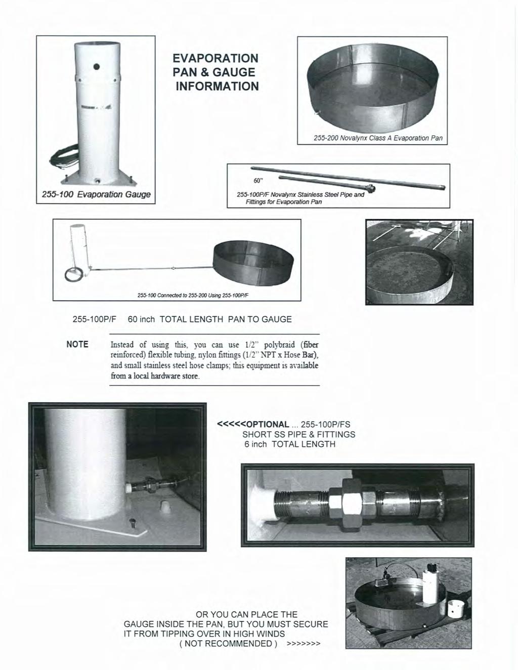
5 1.0 INTRODUCTION 1.1 General Description NovaLynx Corporation Model Analog Output Evaporation Gauge Instruction Manual The Analog Output Evaporation Gauge has been designed to accurately measure the changing water level in an evaporation pan. The evaporation gauge provides an electrical signal proportional to the water level. The data provided can be used to determine the evaporation rate of the water. Although it may be used with a variety of evaporation measuring equipment, the evaporation gauge is normally used with a standard Class A National Weather Service Evaporation Pan (NovaLynx Model ). 1.2 Gauge Design The evaporation gauge design includes a float, a counter-weight, a chain attached to both the float and counter-weight, and a sprocket attached to a precision 1000 ohm potentiometer. The gauge components are all mounted inside a protective enclosure. The housing of the evaporation gauge has been designed to act as a stilling well for the float to help eliminate rapid fluctuations in the measurements. The housing is constructed to hold the water inside it without any leakage to the outside. By using the built-in water pipe coupler, the gauge can be attached to the NovaLynx Evaporation Pan to remotely sense the water level. NovaLynx provides a six-foot interconnecting pipe assembly under model number P/F. The NovaLynx pipe and fittings are stainless steel and the fittings include a stainless steel union to join the two pieces of pipe. This design helps eliminate any influences the gauge may introduce into the evaporation pan measurements that can occur whenever the gauge is inside the evaporation pan. 1.3 Use of Gauge with Evaporation Pan As the level of the water inside the evaporation pan changes, the water inside the evaporation gauge will change to the same level. The float moves on top of the water surface. The float transfers its motion through the chain to the sprocket. The sprocket, in turn, causes the shaft of the potentiometer to rotate, changing the resistance of the potentiometer. Using a regulated dc power source, typically +5 Vdc, to excite the potentiometer, a voltage that varies from zero to Vdc can be measured at the wiper of the potentiometer. The voltage from the potentiometer can be then be translated into inches of evaporated water. The output of the potentiometer is normally wired to give a decreasing voltage as the water level decreases (increasing amount of evaporated water but decreasing water height). In some situations the gauge may be employed as a water level sensor measuring both increasing as well as decreasing 1
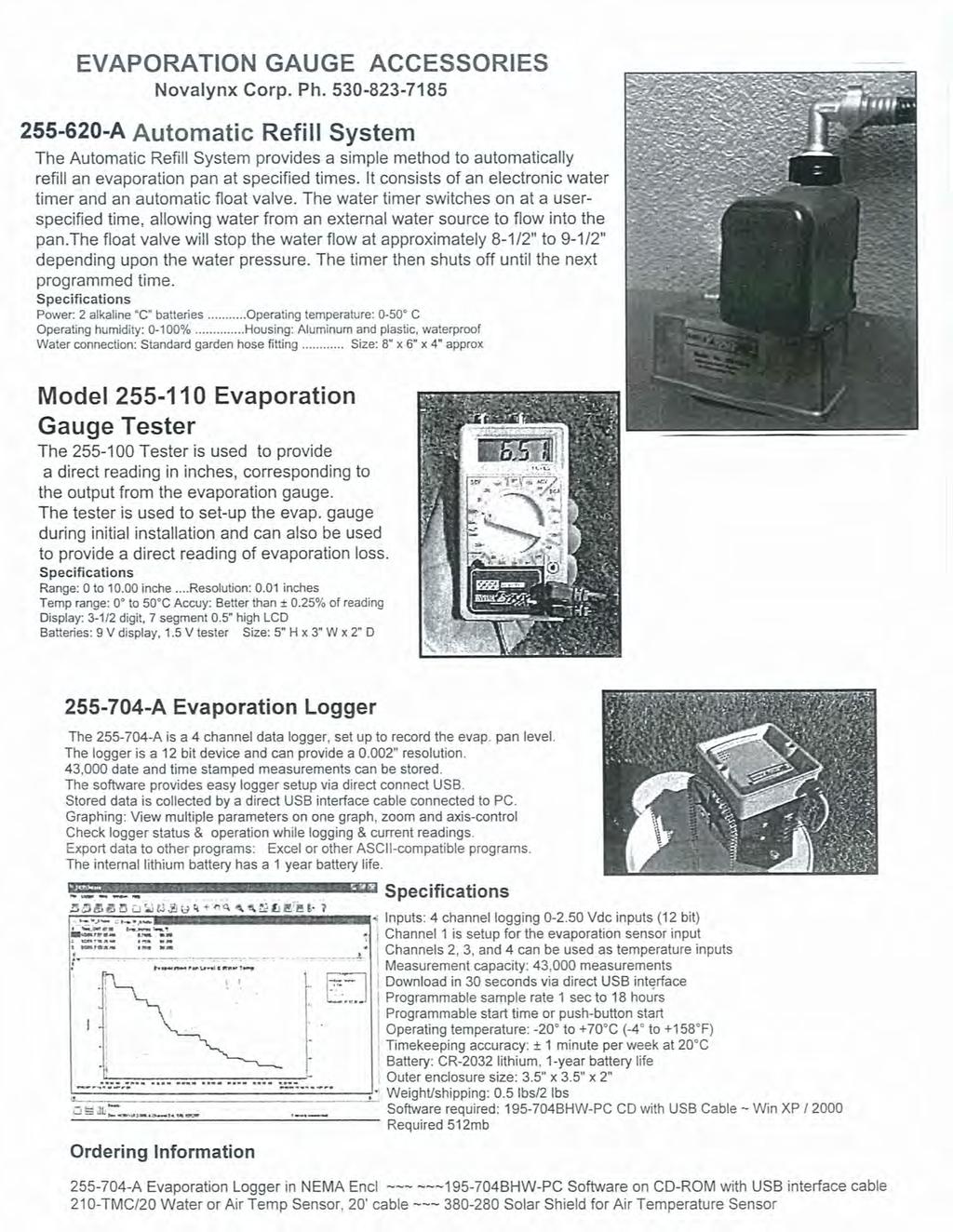
6 levels of water. The maximum amount of water level that can be measured by the gauge is 10 inches. 1.4 Evaporation Gauge Tester (Optional) To aid the user in the set-up, testing, and reading measurements of the evaporation gauge, NovaLynx has developed a handheld tester, Model The tester connects to the evaporation gauge output signal terminal block and converts the sensor's resistance into a direct reading of the evaporation pan water level in inches. The tester features an easy-to-read LCD and a mode selection switch. The tester is self-contained and battery-powered. The instruction manual for the tester provides additional information. 1.5 Automatic Evaporation Pan Refill System (Optional) Evaporation gauges are often used with data loggers to collect and store the data at the gauge location until it is transmitted or downloaded to the operator's computer. NovaLynx has created an automatic evaporation pan refill device, Model A. If a water supply line or water tank is available at the site, the A will turn on the water until the pan is refilled to a level of 8 inches. This can be set to occur daily, weekly, or every few days. The refill time is set by the user. NovaLynx recommends using a refill time such as midnight when evaporation is least likely to occur. Refer to the automatic refill manual for more information. 1.6 Evaporation Logger (Optional) The A is an inexpensive data logger that can be connected to the Evaporation Gauge to provide recording history. 2.0 SPECIFICATIONS GENERAL Height: 27-1/2" (700 mm) Diameter: 8" (203 mm) Weight: 7-1/2 lbs (3.4 kg) Shipping weight: 15 lbs (6.8 kg) Cable: 50' of 3-conductor, 24 AWG, shielded Signal connector: 3-pin terminal block, standard (opposite end of cable terminated to meet monitoring equipment interface requirements) Float: 4" diameter, plastic Counterweight: 4 oz (114 g), stainless steel Water input port: 1/2" NPT coupling, female Base dimensions: 16" triangle with leveling screws Total resolution: 0.03" (0.76 mm) 2
7 POTENTIOMETER Accuracy: 0.25% Rotation: 360 continuous Electrical angle: 340, ± 1 (20 gap) Resistance: 1,000 ohms, ± 10% Operating temperature: -40 to +140 F (-40 to +60 C) Linearity: 0.25% Mechanical range: 0 to 10" (0 to 254 mm) Electrical range: 0 to 9.44 inches (0 to 240 mm) 3.0 INSTALLATION 3.1 Unpacking Carefully unpack all of the evaporation gauge. Remove the top cover. The float with chain and counter-weight are shipped inside the bottom of the gauge housing. Remove packing material from inside the housing. The float cannot be removed without removing the pot/gear assembly housing. Use caution when removing packing materials and parts from inside the gauge. Take care to avoid hitting the potentiometer sprocket wheel. 3.2 Site Selection The evaporation gauge water reservoir is physically connected to the pan by using a 1/2" diameter pipe. Threaded couplings are provided on both the pan and the gauge. Typically, 1/2" rigid water pipe is used to connect the gauge to the pan. A flexible hose tubing may be used, provided it does not deteriorate in outdoor weather conditions. The gauge should be placed far enough away from the pan and on the North side to avoid casting any shadows or reflections inside or onto the sides of the pan. Shadows will affect the evaporation process. Both the evaporation pan and the gauge need to be as level as possible in order to maximize the amount of water that can be poured into and measured in the pan. A level pan will provide uniform exposure of the water to the atmosphere, eliminating uneven depths of water. The site should be level and free of nearby obstructions that can cast shadows or reflect sunlight onto the evaporation pan. The pan should be placed upon a wooden platform over soil typical of the area. Level the platform before installing the pan. Place the pan so that the water pipe fitting faces the evaporation gauge. A second platform for mounting the gauge may be needed in order to place the bottom of the gauge at the same elevation as the pan. 3
8 3.3 Leveling the Gauge Level the gauge by adjusting the three leveling screws located on the triangular base. With the top cover removed, place a carpenters level across the opening and check the level. Adjust the screws until the air bubble in the level is centered. After leveling the gauge look down inside the stillwell to make certain that the float and chain hang down straight and are centered in the gauge. The float must be free to move up and down without making contact with the sides of the gauge. 3.4 Testing for Leaks After connecting the gauge to the pan and all electrical connections are in place, fill the evaporation pan with the desired amount of water and carefully check all of the joints for leaks. Using Teflon tape or plumbers pipe joint compound at each threaded coupling will help prevent leaks. 3.5 Wiring Whenever the gauge is to be used with other equipment, the output signal wiring may vary depending upon the way that the gauge is to be used. The signal and power wires are connected into the gauge through a three-pin terminal block. The terminal block is mounted onto the side of the potentiometer housing. To access the terminal block, the cover must be removed from the gauge. Four screws hold the cover in place. The signal cable is terminated with three spade lugs. The spade lugs are attached to the screws of the terminal block. Refer to the gauge schematic to obtain wiring details. The opposite end of the cable will generally be stripped and tinned. Refer to the table presented below for wiring details Output Signal Connections Power Input 5 Vdc (typical) RED TB PIN 1 ~ TOP Evap Signal 0~5 Vdc (wiper) WHITE TB PIN 2 ~ MIDDLE Power Ground GND BLACK TB PIN 3 ~ BOTTOM 4.0 OPERATION The evaporation gauge potentiometer exhibits a varying resistance in response to the motion of the float. Applying a voltage across the potentiometer allows monitoring of the gauge by a data logger or any other electronic voltage sensing instrument. The output signal of the potentiometer can be configured to give an increasing or a decreasing voltage with regards to the changing level of the water. For most systems provided by NovaLynx, the signal is configured so that a decrease in the water level is represented by a decrease in the gauge voltage. 4
9 The actual starting water level measured is not critical, 8.5" or 9". The reading that is critical is the change or evaporation measured from the starting reference level. The gauge will never read below ~ 1.4 inches This is when the float physically hits the bottom of the gauge, and there is still 1.4 inches of water present. Normal range is typically is 3 inches to 8.5 or 9 inches. Above 9 inches wind could blow water over the edges. Below 3 inches the low level of water absorbs more heat from the sun & bottom pan reflections, causing increased evaporation. Note that during winter months when the water may freeze, NovaLynx recommends draining the pan and storing the pan and the evaporation gauge indoors. 5.0 CALIBRATION The actual calibration is normally done within the measuring device, converting the output voltage change into change in inches or millimeters. Proper calibration of the evaporation gauge is critical to the accuracy of the data as well as to the correct operation of the gauge. Calibration of the gauge is can be performed upon initial installation of the gauge and whenever the gauge is removed from its platform or from inside the evaporation pan. The evaporation gauge must be calibrated in order to set the operating range of the potentiometer and to determine the zero point of the float motion. For data logging systems, the slope and intercept data will be measured or calculated from the calibration of the gauge. After the gauge has been calibrated, the operator needs only to keep track of the amount of water added back into the evaporation pan. With the gauge calibrated, the gauge may be used to measure the amount of water added into the pan each week. The following procedure is used to properly calibrate the evaporation gauge. Record the calibration values whenever possible in order to check the gauge calibration during the year. Note: The actual measuring device or data logger, when properly set up, can be used as the indicating device. This will eliminate the resistance measurements and mathematical calculations described below. 5.1 Upon completion of the gauge and pan installation, fill the evaporation pan with approximately eight inches of water. The water height can be checked by using a ruler or a tape measure. Check the evaporation gauge to ensure that the water has filled the stillwell to the correct height inside the gauge. 5.2 Disconnect the signal cable from the evaporation gauge. Use a digital ohmmeter to measure the resistance of the pot across terminal block pins (2) middle (+) and (3) bottom (-). Rotate the sprocket and you will notice the resistance value 5
10 changes from 0 to 1000 ohms. Rotate the sprocket slowly until the reading jumps to a floating condition or reads 0. This is the dead band it has a mechanical range of about 20. Some pots may be exactly 1K ohm, but most will vary by ± 15 ohms There is a white line marked on the front side of the sprocket. When this line is vertical the pot should be in the 20 gap area. 5.3 Check to make certain that the float is hanging down near the center of the evaporation gauge. As viewed from the front of the gauge, looking toward the face of the sprocket wheel, the float should hang from the right side of the sprocket wheel with the counter-weight to the left side of the wheel. A white line is painted on the front of the sprocket, When viewed from the front side, the line should be at the 11 o clock or 30 when the float is resting on the bottom of the gauge. 5.4 Move the float by hand down toward the bottom of the gauge. As soon as the float contacts the bottom surface of the gauge, hold the float in position and check to see that the chain is straight and tight. The chain must not be moving nor pulled downward other than by the tension exerted by the float. Measure the resistance of the potentiometer. 5.5 The potentiometer should be at its point of low resistance for the range of motion of the pot. The resistance should be above zero ohms but may be as large as 150 ohms. If the value appears to be floating or within the deadband of the potentiometer the sprocket wheel must be adjusted with relation to the chain. The potentiometer must not cross into or go beyond the deadband as the float approaches and touches the bottom of the gauge. To adjust the sprocket, allow the float to return to the top of the water. Lift the chain off the sprocket and rotate the sprocket counter-clock-wise one or two gear tooth positions. Replace the chain and repeat step 5.4. Repeat this step (5.5) until the chain is properly positioned on the sprocket. Observe the ohmmeter to detect any crossover of the deadband as the float is moved downward. 5.6 Record the resistance of this Bottom or Zero position of the float. If the gauge is connected into the monitoring equipment and power has been applied, measure the voltage at this position as well as the resistance. Measure the position of the center of the float with respect to the bottom of the evaporation pan for pan mounted gauges. For gauges mounted outside the pan, measure the water level inside the gauge to the center of the float. Usually, the center of the float is aligned with the center of the threaded pipe fitting on the housing when the float touches the bottom of the gauge. 5.7 Move the float back to the top of the water and let go of the float. The center of the float should now be even with the surface of the water. Measure the resistance and voltage of the potentiometer at this position. Also measure the water level at this point with respect to the bottom of the pan. The resistance of the potentiometer should be high at this point and approaching the 1000 ohm end of the pot. If the chain and sprocket have been properly set, the 6
11 potentiometer should not move past the 1000 ohm end of the element and stop in the deadband. If it appears that the pot is in its deadband at the top of the water level, then either the sprocket and chain must be adjusted further or there is too much water in the pan and some water must be drained. Typically this setting should be offset slightly to avoid going into the gap area. When the pan is full to the brim, the resistance should be between 950 and 995 ohms. When the pan is empty or < 1-1/4" deep, the resistance should be between 20 to 90 ohms. 5.8 At this point the slope and intercept information can be generated and the operating curve of the instrument can be calculated. The operating curve can then be verified by setting the float to several points of water level and by comparing the actual output voltage to the calculated voltage. Remember the gap is 20 therefore 340 /360 = With a 5.00 volt excitation applied, a 5 volt reading on the wiper means 9.44" not 10.0". The formulas are: Y = m*x + b m = (Y 2 - Y 1 ) (X 2 - X 1 ) b = Y 1 - mx 1 where Y is inches of water, X is ohms or volts, m is the slope of the line and b is the zero offset. For a range of 10 inches and a potentiometer resistance of 1000 ohms the calculation reveals that b = 0, and m = For a range of 10 inches and a voltage range of 5 Vdc, b = 0 and m = If the float range of motion happens to be 1.5 to 8.0 inches, then the output voltage can be calculated as 0.75 and volts, respectively. Use the actual values measured in the preceding steps, 4.2, 4.4, 4.6, and 4.7, with the above formulas to determine the operating line of the gauge. The line should be linear allowing calculation of intermediate outputs for known positions of the float. 6.0 TROUBLESHOOTING 6.1 General Inspection Always disconnect the reporting/recording device from its power source before making any changes to the wiring connections. If possible, troubleshoot the gauge immediately whenever any of the following conditions are observed: severe weather has recently occurred; the gauge does not appear to operate normally or exhibits a marked change in performance; the data is missing or appears to be incorrect; the gauge has been dropped or damaged; water has damaged the wiring or electronic components; water has been allowed to dry out totally in the evaporation pan. 7
12 Remember a 90/ rotation on the sprocket should indicate a change of 2.50 inches on your reporting/recording device, 180/ would be a 5.00 inch change. A 1 inch change is equal to approximately 7.6 gallons of water decrease inside the evaporation pan 6.2 Power If the gauge does not register correctly, first check the power connections. Check the voltage with a voltmeter. Be sure the reporting/recording device has been powered up correctly. If the reporting/recording device uses batteries for its primary source of power, check the batteries to be sure they have sufficient voltage and that they are securely in place. Check the battery terminals to ensure that they are clean and provide solid contact. 6.3 Cables Check the sensor cable connections both at the gauge and at the control unit; cable shorts or opens can cause loss of data. If a connection is found to be loose, reattach the wire and check to see if the problem has been corrected. Check for damage to the cable insulation. Replace the cable if it appears that the jacket has been worn or cut open. 6.4 Float Inspect the float and chain to make certain that they have not become entangled. Whenever the evaporation pan has been allowed to empty or dry out completely, the float may tip sideways at the bottom of the gauge and the chain may become kinked at the mechanical connector. Test the motion of the float to ensure that it moves smoothly and freely. 6.5 Natural Influences A number of naturally occurring events can influence the evaporation gauge reading and may appear as errors or as a gauge malfunction. These natural events include animals drinking the water, birds bathing in the water, leaves and debris falling into the pan, high level winds, unreported rainfall or snow during the night, and thermal expansion of the water and metal parts. 6.6 Evaporation Pan Maintenance Additional errors in the evaporation gauge measurement may be related to maintenance of the evaporation pan. The pan must be kept free of algae. Plants must not be allowed to grow up and over the edges of the pan. Dirt and dust must not be allowed to accumulate inside the pan. Most of these problems are alleviated by regular rinsing of the pan. 8
13 The growth of algae in the evaporation pan can be discouraged by the addition of small amounts (5 to 10 mg/liter) of copper sulphate (available at farm and garden supply stores) to the water, however, algae already present must be removed by a thorough cleaning of the pan. In severe cases, spa chemicals may be used to combat algae, however, the addition of chemicals to the water will influence the evaporation process. During months when freezing conditions are likely, empty, clean, and store the pan. The pan should be stored indoors. If it must be left in the fenced enclosure, it should be turned bottom side up and secured to the platform with stout rope. 7.0 DRAWINGS AND DATA LOGGER PROGRAMMING 9
14
15
16
17
18
19
20
21
22
23
NOVALYNX CORPORATION MODEL RAIN GAUGE CALIBRATOR INSTRUCTION MANUAL
 NOVALYNX CORPORATION MODEL 260-2595 RAIN GAUGE CALIBRATOR INSTRUCTION MANUAL REVISION DATE: August 2018 Receiving and Unpacking Carefully unpack all components and compare to the packing list. Notify NovaLynx
NOVALYNX CORPORATION MODEL WEATHER STATION INSTRUCTION MANUAL
 NOVALYNX CORPORATION MODEL 100-1950 WEATHER STATION INSTRUCTION MANUAL Receiving and Unpacking Carefully unpack all components and compare to packing list. Notify NovaLynx Corporation immediately concerning
NOVALYNX CORPORATION MODEL BAROMETRIC PRESSURE SENSOR PCB MODEL BAROMETRIC PRESSURE SENSOR IN NEMA ENCLOSURE INSTRUCTION MANUAL
 NOVALYNX CORPORATION MODEL 230-600 BAROMETRIC PRESSURE SENSOR PCB MODEL 230-601 BAROMETRIC PRESSURE SENSOR IN NEMA ENCLOSURE INSTRUCTION MANUAL REVISION DATE: 11/15/2006 Receiving and Unpacking Carefully
L 100. Bubble-Tube Level System. Installation, Operation and Maintenance Instructions
 L 100 Bubble-Tube Level System Installation, Operation and Maintenance Instructions Figure 1 Contents Section Description Page 1.0 Introduction 2 2.0 Specifications 3 3.0 Installation 3 4.0 Warranty 6
! Warning, refer to accompanying documents.
 About this Manual To the best of our knowledge and at the time written, the information contained in this document is technically correct and the procedures accurate and adequate to operate this instrument
DPC-30 DPC-100. Reference Manual
 DPC-30 DPC-100 Reference Manual 1. Introduction 1.1 Description The Martel DPC Digital Pneumatic Calibrator improves upon traditional dial gauge pneumatic calibrators. The Martel DPC improves accuracy,
STARLOG. Capacitive Water Depth Probe
 STARLOG Capacitive Water Depth Probe Model 6521 User Manual Supplement 6219 Revision D July 10. 1998 Copyright Notice Copyright Unidata Australia 1998. All rights reserved. No part of this publication
INSTRUCTION MANUAL MP4AR Remote Convection Gauge Range: 1 x 10⁻³ Torr to 1 x 10+3 Torr
 INSTRUCTION MANUAL MP4AR Remote Convection Gauge Range: 1 x 10⁻³ Torr to 1 x 10+3 Torr A DIVISION OF THE FREDERICKS COMPANY 2400 PHILMONT AVE. HUNTINGDONVALLEY, PA 19006 PARTS LIST 1 3 4 2 # QTY ITEM DESCRIPTION
User s Guide Temperature Sensor Converter TSC-599
 User s Guide Temperature Sensor Converter TSC-599 ILX Lightwave Corporation 31950 Frontage Road Bozeman, MT, U.S.A. 59715 U.S. & Canada: 1-800-459-9459 International Inquiries: 406-556-2481 Fax 406-586-9405
TD-106-5D TD-106-5D-A Wind Direction Sensor User s Manual
 Relied on Worldwide in the Most Extreme Conditions TD-106-5D TD-106-5D-A Wind Direction Sensor User s Manual Texas Electronics, Inc. Dallas, TX 75237 Fax.214.631.4218 4230 Shilling Way Tel.214-631-2490
GASGUARD VENT LINE3 Ammonia Sensor OPERATING & INSTALLATION MANUAL
 GASGUARD VENT LINE3 Ammonia Sensor OPERATING & INSTALLATION MANUAL Operating and Installation Manual Warning Use this product only in the manner described in this manual. If the equipment is used in a
AUTO PUMP STATUS CENTER
 INSTRUCTION MANUAL AUTO PUMP STATUS CENTER PRESSURE ONLY MODEL #: 091-198-12-AP File: IM_091-198-12-AP_revD.indd Rev: D, pg 3 WD Revised By: PSS Date: 2-01-2016 3 YEAR WARRANTY INTRODUCTION The Auto Pump
INSTALLATION PROCEDURE 1/4 & 1/8 MILE PERMANENT TRACK
 INSTALLATION PROCEDURE 1/4 & 1/8 MILE PERMANENT TRACK 1) Unpack all of the equipment and immediately inspect for shipping damage. Damages should be immediately reported to the carrier and noted on the
Preferred Instruments Danbury, CT USA
 Tank Level Sensor Model TG-EL-WF-xx Installation & Operation Instructions SDI-TG-EL-WF March 6, 2006 Preferred Instruments Danbury, CT USA www.preferredinstruments.com CONTENTS Installation Pg. 2 Calibration
User's Manual. Heavy Duty Dissolved Oxygen Meter. Model
 User's Manual Heavy Duty Dissolved Oxygen Meter Model 407510 Introduction Congratulations on your purchase of Extech's Heavy Duty Dissolved Oxygen / Temperature Meter which simultaneously displays Dissolved
NB/NBR NITROGEN BOOSTER FOR AVIATION SERVICE
 NB/NBR NITROGEN BOOSTER FOR AVIATION SERVICE INSTALLATION, OPERATION & MAINTENANCE MANUAL INTERFACE DEVICES, INC. 230 Depot Road, Milford, CT 06460 Ph: (203) 878-4648, Fx: (203) 882-0885, E-mail: info@interfacedevices.com
MODEL GT820 OXYGEN SENSOR
 INSTRUCTION MANUAL MODEL GT820 OXYGEN SENSOR 70046 The information and technical data disclosed by this document may be used and disseminated only for the purposes and to the extent specifically authorized
J Air and Water Kit Instructions Part# 02584
 J Air and Water Kit Instructions Part# 02584 Unpacking Please open and inspect your package upon receipt. Your package was packed with great care and all the necessary packing materials to arrive to you
GG-VL2-NH3 AMMONIA VENT LINE SENSOR. Installation and Operation Manual
 GG-VL2-NH3 AMMONIA VENT LINE SENSOR Installation and Operation Manual 2 GG-VL2-NH3 Warning Use this product only in the manner described in this manual. If the equipment is used in a manner not specified
Cover Page for Lab Report Group Portion. Pump Performance
 Cover Page for Lab Report Group Portion Pump Performance Prepared by Professor J. M. Cimbala, Penn State University Latest revision: 02 March 2012 Name 1: Name 2: Name 3: [Name 4: ] Date: Section number:
CSA Sample Draw Aspirator Adapter Operator s Manual
 30-0951-CSA Sample Draw Aspirator Adapter Operator s Manual Part Number: 71-0367 Revision: 0 Released: 4/30/15 www.rkiinstruments.com WARNING Read and understand this instruction manual before operating
! WARNING. Model PFC-1-G (direct acting) PFC-1-GR (reverse acting) Modulating Pneumatic Liquid Level Controls INSTRUCTION MANUAL MM-110B
 PFC-1-GR (reverse acting) Modulating Pneumatic Liquid Level Controls INSTRUCTION MANUAL MM-110B") INSTRUCTION MANUAL MM-110B Model PFC-1-G (direct acting) PFC-1-GR (reverse acting) Modulating Pneumatic Liquid Level Controls APPLICATIONS: Use with other pneumatic devices, for liquid level sensing in
INSTRUCTION MANUAL MM-110B Model PFC-1-G (direct acting) PFC-1-GR (reverse acting) Modulating Pneumatic Liquid Level Controls APPLICATIONS: Use with other pneumatic devices, for liquid level sensing in
DTG - LCD Digital Temperature Gauge USER MANUAL
 DTG - LCD USER MANUAL Page 1 of 7 USERS GUIDE page 1. Description 3 2. Function 3 3. Safety Instruction 3 3.1. Safety Conventions 3 3.2. Proper Use 3 4. Installation 4 4.1. Unpacking 4 4.2. Storage 4 4.3.
SPECIFICATIONS APCEPH1
 APCEPH1 ph CONTROLLER SPECIFICATIONS APCEPH1 Input voltage 120 Volts AC Maximum amperage 14.5 amps @ 120 VAC ph Accuracy +/- 0.2 ph ph Control range Adjustable 4.5 8.5 ph Weight < 1 lbs Dimensions 3" x
SDX Submersible Depth Transmitter User Manual
 SDX Submersible Depth Transmitter User Manual October 2007 USER INFORMATION Stevens makes no warranty as to the information furnished in these instructions and the reader assumes all risk in the use thereof.
GETZ EQUIPMENT INNOVATORS PART NO.: 9G59554 MODEL: MS 36 SC-R HYDROSTATIC TEST PUMP
 GETZ EQUIPMENT INNOVATORS PART NO.: 9G59554 MODEL: MS 36 SC-R HYDROSTATIC TEST PUMP LIMITED WARRANTY Getz Equipment Innovators warrants its products, and component parts of any product manufactured by
Electro-Pneumatic Converter YT-940 SERIES
 Electro-Pneumatic Converter YT-940 SERIES PRODUCT MANUAL VERSION 1.00 Contents 1. Introduction 3 1.1 General information for the users. 3 1.2 Manufacturer Warranty 3 1.3 Explosion Proof Warning. 4 2. Product
Mini-Pro CO2 Sensor User s Manual - ANALOG MODEL -
 Mini-Pro CO2 Sensor User s Manual - ANALOG MODEL - Table of Contents 1. Introduction 3 2. Instrument Setup 4 2.1 Instrument Checklist 4 2.2 Optional Accessories 4 2.3 Gas Concentration Ranges Available
PULSAR 5000 SERIES OPERATING & INSTALLATION INSTRUCTIONS SERIES 5000 PLEASE READ CAREFULLY BEFORE INSTALLING
 PULSAR 5000 SERIES OPERATING & INSTALLATION INSTRUCTIONS SERIES 5000 PLEASE READ CAREFULLY BEFORE INSTALLING Please Note: Ranges above 500mbar are designed and manufactured in accordance with sound engineering
SDX Submersible Depth Transmitter User Manual
 SDX Submersible Depth Transmitter User Manual July 2017 USER INFORMATION Stevens makes no warranty as to the information furnished in these instructions and the reader assumes all risk in the use thereof.
Model PSI Compressor with 3-Gallon Air Tank 12VDC
 Model 6350 150 PSI Compressor with 3-Gallon Air Tank 12VDC IMPORTANT: It is essential that you and any other operator of this product read and understandd the contents of this manual before installing
Cover Page for Lab Report Group Portion. Head Losses in Pipes
 Cover Page for Lab Report Group Portion Head Losses in Pipes Prepared by Professor J. M. Cimbala, Penn State University Latest revision: 02 February 2012 Name 1: Name 2: Name 3: [Name 4: ] Date: Section
D Series Air and Water Kit Part# 02550
 D Series Air and Water Kit Part# 02550 Unpacking Please open and inspect your package upon receipt. Your package was packed with great care and all the necessary packing materials to arrive to you undamaged.
OEM Manual MODEL 2305 ECONOMICAL DIGITAL SINGLE CYLINDER SCALE
 OEM Manual MODEL 2305 ECONOMICAL DIGITAL SINGLE CYLINDER SCALE 1 These instructions generally describe the installation, operation, and maintenance of subject equipment. The manufacturer reserves the right
RK-IR Sample Draw Aspirator Adapter Operator s Manual
 30-0951RK-IR Sample Draw Aspirator Adapter Operator s Manual Part Number: 71-0018RK Revision: A Released: 6/2/10 www.rkiinstruments.com Product Warranty RKI Instruments, Inc. warrants gas alarm equipment
E8AA. Pressure Sensor of Stainless Steel Construction Is Ideal for a Wide Range of Applications. Pressure Sensor (Stainless Steel Diaphragm)
") Pressure Sensor (Stainless Steel Diaphragm) CSM DS_E_3_1 Pressure Sensor of Stainless Steel Construction Is Ideal for a Wide Range of Applications Incorporates double diaphragms consisting of SUS316L stainless
Pressure Sensor (Stainless Steel Diaphragm) CSM DS_E_3_1 Pressure Sensor of Stainless Steel Construction Is Ideal for a Wide Range of Applications Incorporates double diaphragms consisting of SUS316L stainless
AWG Fittings LLC. Pressure Relief Valve Up to 250 PSI. Product Number Read this instruction manual before use.
 AWG Fittings LLC Pressure Relief Valve Up to 250 PSI Product Number 30004033 Read this instruction manual before use. Using this device without t understanding di this products operation and care may lead
INSTRUCTION MANUAL. FLOW CONTROL DRAWERS MANUAL / PLC CONTROL SERIES Model Version Perma Pure LLC Tel:
 PERMA PURE INSTRUCTION MANUAL FLOW CONTROL DRAWERS MANUAL / PLC CONTROL SERIES Model 3300 Version 4.06 Perma Pure LLC Tel: 732-244-0010 P.O. Box 2105, 8 Executive Drive Tel: 800-337-3762 (toll free US)
Model 106 DPI "Micro-switch" Installation and Operating Instructions
 Mid-West Instrument Model 106 DPI "Micro-switch" Installation and Operating Instructions BULLETIN NO. IM116DPImicro/09A Replaces --- INSPECTION Before installation carefully check the Model Number on each
97C COMPRESSOR KIT 12V PART NO C COMPRESSOR KIT 24V PART NO C COMPRESSOR KIT PART NO
 97C COMPRESSOR KIT 12V PART NO. 00097 97C COMPRESSOR KIT 24V PART NO. 02497 98C COMPRESSOR KIT PART NO. 00098 97C 98C IMPORTANT: It is essential that you and any other operator of this product read and
210 Series Transmitter with External Electrochemical Sensor
 210 Series Transmitter with External Electrochemical Sensor INSTRUCTIONS Installation and Operation of the AMC-210 Series Transmitter with External Electrochemical Sensor IMPORTANT: Please read these installation
TECHNICAL DATA. Trimpac 244a. September 16, 2013
 September 16, 2013 Trimpac 244a 1. DEsCrIpTION DESCRIPTION TRIMPAC Model B-1 and B-1B is a factory-assembled trim package with an electric release module in a metal enclosure. The standard trim normally
WATER HEATER THERMAL EXPANSION TANKS Owner s Manual. Safety Instructions Installation Maintenance Warranty. Models: 2-5 Gallon Capacity
 WATER HEATER THERMAL EXPANSION TANKS Owner s Manual Safety Instructions Installation Maintenance Warranty Models: 2-5 Gallon Capacity Thank You for purchasing this Thermal Expansion Tank. Properly installed
Precision Liquid Settlement Array Manual
 Precision Liquid Settlement Array Manual All efforts have been made to ensure the accuracy and completeness of the information contained in this document. RST Instruments Ltd reserves the right to change
American Weigh Scales, Inc. BLADE Series D i g i t a l P o c k e t S c a l e BLADE-550. User Manual BLADE-400 BLADE-1000
 American Weigh Scales, Inc. BLADE Series D i g i t a l P o c k e t S c a l e BLADE-50 BLADE-400 BLADE-550 BLADE-1000 User Manual Blade Series Manual Thank you for purchasing the American Weigh BLADE-Series
42045 Heavy Duty ADA Base Model Kit: 85/105 PSI (ADA Compressor Only) Heavy Duty ADA Base Model Kit: 110/145 PSI (ADA Compressor Only)
 Heavy Duty ADA Base Model Kit: 110/145 PSI (ADA Compressor Only)") 42045 Heavy Duty ADA Base Model Kit: 85/105 PSI (ADA Compressor Only) 42047 Heavy Duty ADA Base Model Kit: 110/145 PSI (ADA Compressor Only) 45052 Constant Duty ADA Base Model Kit: 85/105 PSI (ADA Compressor
42045 Heavy Duty ADA Base Model Kit: 85/105 PSI (ADA Compressor Only) 42047 Heavy Duty ADA Base Model Kit: 110/145 PSI (ADA Compressor Only) 45052 Constant Duty ADA Base Model Kit: 85/105 PSI (ADA Compressor
Air Bubbler Depth Gauge DG2200 Installation and Reference Manual
 Air Bubbler Depth Gauge DG2200 Installation and Reference Manual Rev. 3.2.2 06/2011 Installation and Reference Manual Page 2 Contents Chapter 1: Installation and Overview... 3 1.1 DG2200 Location Diagram...
Model DPC3500 Continuous Low Range Dew Point Analyzer. Operations Manual
 Model DPC3500 Continuous Low Range Dew Point Analyzer Operations Manual Please read, understand, and follow these instructions before operating this equipment. Super Systems, Inc. is not responsible for
In Vivo Scientific, LLC INSTRUCTION MANUAL
 CO 2 Controller In Vivo Scientific, LLC INSTRUCTION MANUAL CONTENTS CONTENTS...1 ABOUT THIS MANUAL...2 INTRODUCTION...2 Cautions and Warnings...2 Parts List...2 Unpacking...2 INSTRUMENT DESCRIPTION...3
GILMONT ACCUCAL FLOWMETERS
 OPERATING MANUAL GILMONT ACCUCAL FLOWMETERS 28W092 Commercial Ave. Barrington, IL U.S.A. 60010-2392 (847) 381-4888 (847) 381-7053 (Fax) 800-962-7142 www.barnant.com e-mail: barnant@barnant.com A-1299-0766
DeltaSpan Pressure Transmitters LD10 Series Owner s Manual
 Warranty, Service & Repair To register your product with the manufacturer, fill out the enclosed warranty card and return it immediately to: Flowline Inc. 10500 Humbolt Street Los Alamitos, CA 90720. If
PERSONAL AIR BREATHING UNIT
 PERSONAL AIR BREATHING UNIT Operation & Maintenance Manual MARTECH SERVICES C O M P A N Y 1-800-831-1525 Table of Contents INTRODUCTION: Page 2 COMPONENTS DRAWING: Page 3 START UP: Page 4 OPERATION: Page
RAM Operation Manual. Worldwide Manufacturer of Gas Detection Solutions
 RAM 4021 Operation Manual Worldwide Manufacturer of Gas Detection Solutions TABLE OF CONTENTS RAM 4021 For Your Safety... 2 Description.... 2 Setup Mode.... 2 Lights/Alarms.... 3 Operation.... 4 Calibration....
200 PSI COMPRESSORS - MODEL NUMBERS
 200 PSI COMPRESSORS - MODEL NUMBERS 380C AIR COMPRESSOR KIT PART NO. 38033 480C AIR COMPRESSOR KIT PART NO. 48043 380C 480C IMPORTANT: It is essential that you and any other operator of this product read
RAM 4021-PR. Operation Manual. Worldwide Manufacturer of Gas Detection Solutions
 RAM 4021-PR Operation Manual Worldwide Manufacturer of Gas Detection Solutions TABLE OF CONTENTS RAM 4021-PR For Your Safety... 2 Description.... 2 Setup Mode.... 2 Lights/Alarms.... 3 Operation.... 4
Harvard Trip Balance BA710. Impact Test Equipment Ltd & User Guide. User Guide
 Harvard Trip Balance BA710 Impact Test Equipment Ltd www.impact-test.co.uk & www.impact-test.com User Guide User Guide Impact Test Equipment Ltd. Building 21 Stevenston Ind. Est. Stevenston Ayrshire KA20
RAM Operation Manual. Worldwide Manufacturer of Gas Detection Solutions
 RAM 4021 Operation Manual Worldwide Manufacturer of Gas Detection Solutions TABLE OF CONTENTS RAM 4021 For Your Safety... 2 Description.... 2 Setup Mode.... 2 Lights/Alarms.... 3 Operation.... 4 Calibration....
2 GALLON TWIN STACK AIR COMPRESSOR W/ HOSE REEL
 2 GALLON TWIN STACK AIR COMPRESSOR W/ HOSE REEL Model: 52024 CALIFORNIA PROPOSITION 65 WARNING: You can create dust when you cut, sand, drill or grind materials such as wood, paint, metal, concrete, cement,
OEM Manual. MODEL ½ Digit DRUM SCALE
 OEM Manual MODEL 4020-3 ½ Digit DRUM SCALE Scaletron Industries, Ltd. Bedminster Industrial Park 53 Apple Tree Lane P.O. Box 365 Plumsteadville, PA 18949 USA Toll Free: 1-800-257-5911 (USA & Canada) Phone:
TANK MANAGER FOR TWO TANKS OPERATING MANUAL. 10/31/11 C-More T6C L color touch panel
 TANK MANAGER FOR TWO TANKS OPERATING MANUAL 10/31/11 C-More T6C L color touch panel 1 TABLE OF CONTENTS GENERAL...3 INSTALLATION...4 STONE TEST PROCEDURE...7 OPERATIONAL SUMMARY...7 AUTO CARBONATION...10
100C Air Compressor Kit
 10010 100C Air Compressor (standard mounting bracket, CE Spec) 10014 100C Air Compressor (no leader hose or check valve, CE Spec) 10016 100C Air Compressor (with Omega Bracket, CE Spec) IMPORTANT: It is
TECHNICAL DATA. Trimpac 251a. Spetember 16, 2013
 Spetember 16, 2013 Trimpac 251a 1. DEsCrIpTION DESCRIPTION TRIMPAC Model B-6 and B-6B is a factory assembled trim package for a double interlocked preaction system with an electric/pneu-lectric release
WL16 WATER LEVEL LOGGERS Submersible pressure transducer and USB datalogger combination
 WL16 WATER LEVEL LOGGERS Submersible pressure transducer and USB datalogger combination Warning: Non-vented water level loggers may have readings with errors of up to 250mm due to barometric pressure changes.
Portable Compressed CO 2 Regulator
 Portable Compressed CO 2 Regulator 99901 Operating Instructions Distributed exclusively by Harbor Freight Tools. 3491 Mission Oaks Blvd., Camarillo, CA 93011 Visit our website at: http://www.harborfreight.com
INSTRUCTION MANUAL. January 23, 2003, Revision 0
 INSTRUCTION MANUAL Model 810A In-Vitro Test Apparatus for 310B Muscle Lever January 23, 2003, Revision 0 Copyright 2003 Aurora Scientific Inc. Aurora Scientific Inc. 360 Industrial Parkway S., Unit 4 Aurora,
Advanced Test Equipment Rentals ATEC (2832)
") WARRANTY CLAUSE METROSONICS warrants each new cl-304 manufactured and sold to be free from defects in material, workmanship and construction, except for batteries which may be contained therein, and that
WARRANTY CLAUSE METROSONICS warrants each new cl-304 manufactured and sold to be free from defects in material, workmanship and construction, except for batteries which may be contained therein, and that
Transmitter CS 21 Operation Manual
 Transmitter CS 21 Operation Manual Content Page For your Safety 3 General Description 3 Detection Principle 4 Operational Notes 4 Design 4 Mounting Position of CS21 5 Mounting 6 Installation of Electrical
MODEL WEIGH MODULE
 MODEL 65082 WEIGH MODULE INSTALLATION & OPERATING MANUAL P.O. Box 775 - Farmington, NH 03835 Tel: 603-755-3885 email: cands_nh@msn.com www.candscontrols.com Model 65023 Cantilever Beam Transducer Nickel-Plated
_ pressure transducers. User Manual
 _ pressure transducers User Manual summary introduction DescriPTION preliminary checks Installation taking measurements data management Troubleshooting maintenance Appendix 1 Page 4 Page 5 Page 6 Page
Dual Solenoid Gas Valve Installation
 Installation IMPORTANT: These instructions are intended as a guide for qualified personnel installing or servicing FLYNN Gas Products. Carefully follow all instructions in this bulletin and all instructions
SPECIFICATIONS Type: Twin stack, single phase Tank: 4 gallon Air Output: PSI; PSI Max PSI: 125 PSI HP: 1.
 2 GALLON TWIN STACK AIR COMPRESSOR Model: 9526 DO NOT RETURN TO STORE. Please CALL 800-348-5004 for parts and service. CALIFORNIA PROPOSITION 65 WARNING: You can create dust when you cut, sand, drill or
Deep Submersible Level Transducer Series 300DS
 KPSI Transducers Deep Submersible Level Transducer Series 300DS FEATURES! Custom Level Ranges up to 4614 ft (1408 m) H 2 O! Accuracy of ±0.5% FS! Analog Outputs of 4-20 ma or 0-5 VDC! Welded 316 SS Construction!
Copyright 2004 by the Thomas G. Faria Corporation, Uncasville CT No part of this publication may by reproduced in any form, in an electronic
 Copyright 2004 by the Thomas G. Faria Corporation, Uncasville CT No part of this publication may by reproduced in any form, in an electronic retrieval system or otherwise, without the prior written permission
UBEC 1AT. AUTO TANK Fill System Installation, Operation, & Setup Instructions
 Document Number: XE-ATA5PM-R1A UBEC 1AT AUTO TANK Fill System 08899155 Installation, Operation, & Setup Instructions Rev170906-EB-FRC PHYSICAL: 1302 WEST BEARDSLEY AVE ELKHART, IN 46514 WWW.ELKHARTBRASS.COM
AIR COMPRESSOR. Failure to follow all instructions as listed below may result in electrical shock, fire, and/or serious personal injury.
 2 GALLON AIR COMPRESSOR Model: 7517 DO NOT RETURN TO STORE. Please CALL 800-348-5004 for parts and service. CALIFORNIA PROPOSITION 65 WARNING: You can create dust when you cut, sand, drill or grind materials
Installation and Operation Manual
 Installation and Operation Manual WIKA FLR-SBDF / BLR-SBDF Magnetic Level Transmitter (Please retain for future usage) Contact: Gayesco-WIKA USA, L.P. 229 Beltway Green Boulevard Pasadena, TX 77503 www.wika.com
PRESSURE SENSOR - ABSOLUTE (0 TO 700 kpa)
") Instruction Sheet for the PASCO Model CI-6532A PRESSURE SENSOR - ABSOLUTE (0 TO 700 kpa) 012-06859B 10/98 $1.00 polyurethane tubing syringe cable with DIN s to computer interface quick release s (4) pressure
Instruction Sheet for the PASCO Model CI-6532A PRESSURE SENSOR - ABSOLUTE (0 TO 700 kpa) 012-06859B 10/98 $1.00 polyurethane tubing syringe cable with DIN s to computer interface quick release s (4) pressure
5 Channel Calibrator
 212 N. Woodwork Lane Palatine, IL 60067 800-223-3977 5 Channel Calibrator Part # 0724 User Manual Questions? Contact us at 800-223-3977 or online at http://www.cleanair.com/equipment/express/main.html
GEN-1e CO2 Generator OVERVIEW INSTALLATION PROPANE GENERATORS ONLY NATURAL GAS GENERATORS ONLY
 GEN-1e CO2 Generator Custom Automated Products offers economical and safe carbon dioxide generators. They produce CO2 by burning either propane or natural gas. We have designed our CO2 generator to allow
Installation, operating and maintenance Instructions for Seemag bypass level indicator
 Issue: S Date: 05-09-14 Type G35 General information The Seetru bypass magnetic level indicator, abbreviate SEEMAG, serves to show the filling level of fluids in tanks, basins, tubes etc. The Seemag operates
GAS FUEL VALVE FORM AGV5 OM 8-03
 ALTRONIC AGV5 OPERATING MANUAL GAS FUEL VALVE FORM AGV5 OM 8-03 WARNING: DEVIATION FROM THESE INSTALLATION INSTRUCTIONS MAY LEAD TO IMPROPER ENGINE OPERATION WHICH COULD CAUSE PERSONAL INJURY TO OPERATORS
453 Series Steam Heated Vaporizing Regulator
 ADI 0453A Certified ISO 9001:2000 453 Series Steam Heated Vaporizing Regulator INSTALLATION AND OPERATION INSTRUCTIONS Before Installing or Operating, Read and Comply with These Instructions Controls Corporation
Model B Wire Wet Oxidant Gas Transmitter. 6 Iron Bridge Drive Unit 1 & 2 Gatehead Business Park
 Model B12-69 2-Wire Wet Oxidant Gas Transmitter Home Office European Office Analytical Technology, Inc. ATI (UK) Limited 6 Iron Bridge Drive Unit 1 & 2 Gatehead Business Park Collegeville, PA 19426 Delph
MODEL 100 NITROGEN INFLATION CART
 MODEL 100 NITROGEN INFLATION CART Installation & Operation Information Branick Industries, Inc. 4245 Main Avenue P.O. Box 1937 Fargo, North Dakota 58103 REV120106 P/N: 81-0113 TABLE OF CONTENTS SAFETY
420C AIR COMPRESSOR KIT PART NO C AIR COMPRESSOR KIT PART NO
 420C AIR COMPRESSOR KIT PART NO. 42042 460C AIR COMPRESSOR KIT PART NO. 46043 420C 460C IMPORTANT: It is essential that you and any other operator of this product read and understand the contents of this
Type 3709 Pneumatic Lock-up Valve. Translation of original instructions. Mounting and Operating Instructions EB 8391 EN
 Type 3709 Pneumatic Lock-up Valve Translation of original instructions Mounting and Operating Instructions EB 8391 EN Edition July 2017 Note on these mounting and operating instructions These mounting
FTS SUBMERSIBLE PRESSURE TRANSMITTER USER S MANUAL
 FTS SUBMERSIBLE PRESSURE TRANSMITTER USER S MANUAL TABLE OF CONTENTS PRODUCT OVERVIEW 2 I - USE AND CARE: 3 II - INSTALLATION: 5 III - GENERAL MAINTENANCE TIPS: 5 IV - APPENDIX: A-1 2-WIRE CURRENT LOOP
RK LEL Sample Draw Aspirator Adapter Operator s Manual
 30-0951RK LEL Sample Draw Aspirator Adapter Operator s Manual Part Number: 71-0017RK Revision: A Released: 6/2/10 www.rkiinstruments.com Product Warranty RKI Instruments, Inc. warrants gas alarm equipment
Rejuvenation Instructions
 Rejuvenation Instructions #401 Air Systems UPR This NRI covers the following: Understanding the applications and operation of flow meters. Understand the application and operation of test pressure gauges.
10 DRIP NOZZLE WATERING DRIP KIT Model / Model 46095
 10 DRIP NOZZLE WATERING DRIP KIT Model 93261 / Model ASSEMBLY AND OPERATING INSTRUCTIONS Due to continuing improvements, actual product may differ slightly from the product described herein. 3491 Mission
MASS-STREAM TM Instruction Manual. D-6200 Analog Mass Flow Meters / Controllers
 MASS-STREAM TM Instruction Manual D-6200 Analog Mass Flow Meters / Controllers Doc. No.: 9.17.112A Date: 17-03-2017 ATTENTION Before installing and operating the instrument it is strongly recommended that
MODEL CALIBRATION GAS DELIVERY SYSTEM
 MODEL 1200-26 CALIBRATION GAS DELIVERY SYSTEM Sierra Monitor Corporation 1991 Tarob Court, Milpitas, CA 95035 (408) 262-6611 MODEL 1200-26 CALIBRATION GAS DELIVERY SYSTEM APPLICABILITY & EFFECTIVITY This
RAM Operation Manual
 RAM 4021-1 Operation Manual Worldwide Manufacturer of Gas Detection Solutions TABLE OF CONTENTS RAM 4021-1 For Your Safety... 2 Description... 2 Setup Mode... 3 Lights/Alarms... 3 Operation... 4 Calibration...
TECHNICAL DATA. TRIMPAC Model B-5 & B-5B
 September 16, 2013 Trimpac 250a 1. DESCRIPTION DEsCRIPTIoN is a factory assembled trim package for a ed an electric/pneumatic release module in a metal enclosure. The standard trim normally required on
FlashGARD HP Reverse Osmosis Filtration System Model Number FSTMO75 Part Number
 3M Water Filtration Products FlashGARD HP Reverse Osmosis Filtration System Model Number FSTMO75 Part Number 56123-06 Installer: Please leave this manual with owner/operator. End User: Please retain for
R E D I C O N T R O L S
 R E D I C O N T R O L S Operation & Maintenance Manual Portable Service Purger for Low Pressure Chillers Model: PSP-LP-1B For Refrigerants R-11, R-113, R-114 & R-123 & Other Similar Refrigerants File Literature
M5400 Operators Manual
 M5400 Operators Manual For Veterinary Use Only Supera, LLC Copyright 2012 Examination and Preparation for Use Thank you for ordering an Supera Anesthesia Innovations anesthesia machine! We are delighted
OC Panel High Limit Aquastat Kit, Manual Reset p/n
 OC Panel High Limit Aquastat Kit, Manual Reset p/n 233202 Instruction Sheet APPLICATION The OC (Option Control) Panel High Limit Aquastat Kit provides electronic temperature sensing in a UL limit-rated
MODEL 1329 Tank Gauge
 SERVICE INSTRUCTIONS FOR PETRO-METER 1329 GAUGE SERVICE INSTRUCTIONS MODEL 1329 Tank Gauge www.petro-meter.com Petro-Meter 1329 series Service Instructions HOW TO DETERMINE IF A PETRO-METER IS IN GOOD
MODEL 154XST INSTALLATION AND SERVICE INSTRUCTIONS FOR MODEL 154XST STROBE LIGHT FOR USE IN HARSH ENVIRONMENTS/ HAZARDOUS LOCATIONS
 MODEL 154XST INSTALLATION AND SERVICE INSTRUCTIONS FOR MODEL 154XST STROBE LIGHT FOR USE IN HARSH ENVIRONMENTS/ HAZARDOUS LOCATIONS 2561762B REV. B 210 Printed in U.S.A. INSTALLATION AND SERVICE INSTRUCTIONS