OVERVIEW pg 3. Major Points to Consider pg 3 Minor Points to Consider pg 3. INSTRUCTIONS pg 4
|
|
|
- Leonard Gordon
- 6 years ago
- Views:
Transcription


1
2 TABLE OF CONTENTS OVERVIEW pg 3 Major Points to Consider pg 3 Minor Points to Consider pg 3 INSTRUCTIONS pg 4 How Does Nordic Freeze Work pg 4 How Long Will the Ice Plug Take to Form pg 4 How Do I Know if the Ice Plug has Formed pg Once Formed, How Long Will the Ice Plug Last pg The Co2 Cylinder pg How Many Freezes can I get from A 9. Kg, ( 20 Lb ), Cylinder pg 6 Can Nordic Freeze, Freeze Hot Water pg 6 Will the Ice Plug Burst the Pipe pg 6 What Pressure will the Plug Hold pg 6 Can I Weld, Braze or Solder near an Ice Plug pg 6 When the Job is Finished, What Should I do with the Dry Ice in the Jacket Cavity pg 7 Freeze Alternatives to Piping Systems pg 7 Common Sense pg 7 Hose / Cylinder Connection Instructions for Nordic Freeze Kit pg NORDIC FREEZE JOB RECORD LOG pg 9 Toll Free Anywhere in North America Page 2 of 9
3 OVERVIEW All of the information compiled below comes from 33 years, ( since 92 ), of experience in the Industry. Many of the points touched on come directly from Contractor experiences that have been relayed to MAG Tool Inc. MAG Tool retains no liability for any problems that may arise from the use of our Nordic Freeze Pipe Freezing System, or other systems sold by MAG Tool Inc. If Double Freezing, additional components will be required. Please consult the Tech Sheet or call the Factory Nordic Freeze can save time and money when repairs or new installations are needed on piping systems. Nordic Freeze freezes the water in the pipe to form a temporary stop valve made of ice. With Nordic Freeze there is no need to drain the system or shut off the supplies, so you get through the work much faster and easier. Nordic Freeze is clean, fast and effective. The technique by which one or more temporary ice plugs are used to isolate sections of a piping system is recognized as the most effective method of maintenance and repair, eliminating totally the need to drain down the lines. Nordic Freeze is a simple, easy to use and economical pipe freezing system. Major Points to Consider: Safe Quick Inexpensive No need to drain down the system No loss of expensive or corrosive chemicals No expensive re-testing of chemical concentrations Shutoff capability from outside of the building Equipment isolation when servicing Cross connection prevention insurance Increased productivity of small crews responsible for large systems Minor Points to Consider: There have been 0,000 freeze kits sold in London, England alone, ( 96 ) English sales are,00 per year, ( 96 ) The most common freeze is 3 mm, ( -/2" ) The biggest North American market is Hospitals Discourage the practice of turning the bottles upside down if a Bottom Siphon Cylinder cannot be found MAG Tool Inc. stocks the dip tubes Toll Free Anywhere in North America Page 3 of 9
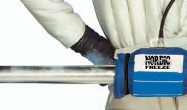
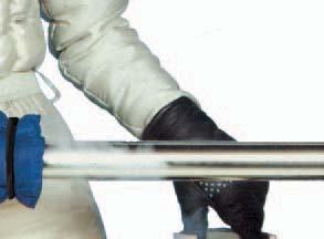
4 INSTRUCTIONS. HOW DOES NORDIC FREEZE WORK Liquid Carbon Dioxide is held under pressure in a CO2 Siphon Cylinder. When the cylinder valve is opened, the liquid CO2 runs through the hose and into the cavity formed by the Nordic Freeze Jacket, which has been fastened around the pipe. The liquid CO2, upon reaching atmospheric pressure and temperature, immediately turns to a mixture of CO2 gas and dry ice. The dry ice has a temperature of -43 C, ( -09 F ), and this intense cold will freeze the water in the pipe. A microscopic view of the inside of a pipe would show a roughness, which grips the ice plug as it is formed when the CO2 is applied. There are literally thousands of these little grippers on the inside of the pipe. With the expanding of the fluid inside, and the shrinking of the pipe carrying the liquid, a very effective seal is formed. 2. HOW LONG WILL THE ICE PLUG TAKE TO FORM This depends on the size of the pipe and the temperature of the water. The following table gives the approximate freezing times for unpainted pipe containing static cold 20 C, ( 6 F ), degrees or colder. Pipe Jacket NF mm ( " ) Pipe Size 3mm 9mm ( /2" ) ( 3/4" ) # of Injections Injection Time Waiting Time Total Time ( min ) NF mm ( " ) 2mm ( " ) Freeze Table ( to be used as a guide only ) 3mm ( _/2" ) NF mm ( 4" ) mm ( 2" ) 76mm ( 3" ) NF9004 0mm ( 20" ) 76mm ( 3" ) NF mm ( 2" ) 02mm( 4" ) 7mm( " ) mm( 6" ) 7mm ( 7" ) NF 900 3mm ( 33" ) CO2 Req..44kg lb 3.44kg lb.kg 3lb 24 3kg 6lb 30 kg lb 60 6kg 36lb 6 4 9kg 42lb kg 6lb 0 0kg 243lb kg 297lb 300 3kg 40lb 203mm ( " ) kg 47lb Notes: Steel and copper pipe take about the same amount of time to freeze. Plastic pipe can take - 6 times longer to freeze than copper pipe and in some cases cannot be frozen. Plastic pipe is very difficult to freeze, use caution. Painted pipes take longer to freeze than unpainted pipes. Clean a painted pipe prior to freezing, if possible. Pipe containing warm water takes longer to freeze than those full of cold water. Vertical pipes will usually take longer to freeze than horizontal pipes. It is important to note that the injection time, the waiting time and the total time required for various pipe sizes, as shown in the Chart, is to be used as a guide only. Room and water temperature will cause all of these factors to vary. Toll Free Anywhere in North America Page 4 of 9
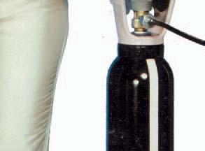
5 3. HOW DO I KNOW IF THE ICE PLUG HAS FORMED Firstly, by having followed the correct injection time and waiting time for the pipe size. Secondly, by checking if the pipe is equally cold on both sides of the Nordic Freeze Jacket. Thirdly, by looking for frost on the pipe on both sides of the Nordic Freeze Jacket. If you are not sure that an ice plug has formed, inject CO2 once more and wait a few more s. Do not test for an ice plug too early or you may destroy a partially formed plug. It is a good idea to crack a flange, or break a bonnet on a valve close to the freeze prior to cutting the line open. If neither exists, drill a. mm, ( /6" ), hole in the pipe to check for excessive pressure. If for some reason the freeze didn't work this hole is easily plugged with a wood dowel or a plastic coated screw. 4. ONCE FORMED, HOW LONG WILL THE ICE PLUG LAST If the cavity created by the Nordic Freeze jacket is kept full of dry ice, the ice plug will remain solid and will not melt. If the jacket is left on the pipe, the ice plug can take anywhere from a few s to a few hours, depending on the size of the pipe, how much of the dry ice has evaporated, room and water temperature, etc. If the Nordic Freeze jacket is taken off the pipe, the ice plug will melt in 3-0 s. If working on an extended repair, inject CO2 every s once the ice plug has been formed. This procedure will maintain a freeze for as long as required. Keep track of your injections in the Nordic Freeze log.. THE CO2 CYLINDER The CO2 Cylinder NF Kg 0 Lb 24. Kg 3 Lb empty 3.4 Kg 03 Lb full 2. Kg 4 Lb usable gas 0.9 Kg 2 Lb residual The CO2 Cylinder NF Kg 20 Lb 3.9 Kg 29 Lb empty 22.3 Kg 49 Lb full.2 Kg Lb usable gas 0.9 Kg 2 Lb residual Toll Free Anywhere in North America Page of 9
6 6. HOW MANY FREEZES CAN I GET FROM A 9. kg, ( 20 lb ), CYLINDER - 0 on 9.04 mm, ( 3/4" ), diameter pipe. 3 - on 2.40 mm, ( " ), diameter pipe. 2-3 on 3.0 mm, ( -/2" ), diameter pipe. - 2 on 0.0 mm, ( 2" ), diameter pipe. When freezing over 0.0 mm, ( 2" ), diameter pipe, we recommend that at least two tanks be on hand to ensure that a sufficient amount of CO2 is available. Also, as stated previously, the room and water temperature will cause both the freezing time and CO2 consumption to vary. These figures are intended as a guide only. When renting Bottom Siphon Cylinders from the Local Gas Supply House, ensure they are Bottom Siphon. Remember to add the NF-902 Valve Seal supplied in the NF Kit to prevent excess flow, and remember to remove the Valve Seal when you return the Rented Cylinder. 7. CAN NORDIC FREEZE, FREEZE HOT WATER Yes, but it is difficult. Place two Nordic Freeze Jackets side by side, touching each other. This will act as a single, double - length jacket. Inject CO2 into both jackets simultaneously which will produce a double convection current in the hot water, and should freeze the water. If double jacketing, keep the jackets abutted to prevent an ice plug from coming out the side of the pipe between the two jackets. We recommend taping the two NF Jackets together with Duct Tape to prevent separation. Allow 2-4 times as long on our times indication and 2-4 times as much CO2. When the pumps are shut down to isolate a system, ensure the adjacent valves are closed as well. To effect a good freeze you need a static head and a full pipe of fluid. We recommend that extra CO2 tanks be available, as a great amount of CO2 will be used. Warm horizontal pipes are easier to freeze than warm vertical pipes. WILL THE ICE PLUG BURST THE PIPE The ice plug will not extend beyond the width of the Nordic Freeze Jacket. Therefore, the pressure increase in the closed section of the pipe will be small. If you use two Nordic Freeze Jackets to isolate both incoming pressure and head pressure, keep them at least mm, ( 24" ), apart. In the case above, the pressure increase will be less than 0 lbs / inch2, ( 3 Bar ). An example of this application would be in reference to a valve change out, or Tee cut in. 9. WHAT PRESSURE WILL THE PLUG HOLD In a laboratory test, an ice plug withstood a pressure of 0,000 lbs / inch2, ( 690 Bar ). 0. CAN I WELD, BRAZE OR SOLDER NEAR AN ICE PLUG Yes, but be sure that the Nordic Freeze Jacket cavity is full of dry ice. Work at least pipe diameters or a minimum of mm, ( 6" ), away from the jacket, ( on a small pipe diameter ), to prevent the cold pipe from affecting the welding, brazing or soldering. Stay mm, ( 24" ), away from closed ends, bends or bull headed tees. The use of "Hot Dam" as supplied with your Nordic Freeze Kit, or a bucket of water and some rags to prevent the heat from traveling toward the ice plug is always recommended. Toll Free Anywhere in North America Page 6 of 9
7 . WHEN THE JOB IS FINISHED, WHAT SHOULD I DO WITH THE DRY ICE IN THE JACKET CAVITY The dry ice will evaporate by itself within a few s. It can be placed in a trash can or flushed down a drain. Be sure that unaware adults, children or animals do not come in contact with dry ice. Always wear protective gloves when handling dry ice. Do not thaw the frozen pipe with a torch, allow it to thaw naturally.. FREEZE ALTERNATIVES TO PIPING SYSTEMS Shafts for installing bearings and gears. Transmitters used in the Oil Patch must be - 40 C, ( - 40F ). 3. COMMON SENSE Use it! As in the case of the rubber mallet supplied with the Nordic Freeze Kit. This is not used to straighten bananas as some would think. But rather, the mallet is used to pound on the outside of the Nordic Freeze Jackets whilst injecting the liquid Carbon Dioxide, to ensure the dry ice is properly formed around the complete circumference of the pipe, and not just close to or at the injection point / points. CO2 is heavier than air. If using Nordic Freeze in a confined area, the waste Carbon Dioxide can displace the Oxygen. Provide proper ventilation. After the initial injection, if the jacket feels empty, inject again until the jacket feels full. Turn off the valve and wait the suggested waiting time between injections. Be sure to complete the number of injections and waiting times. Be sure to have extra CO2 on hand. If your Jacket is full and rock hard prior to the last injection, don't put the last injection in, you may split the Jacket. If unsure as to what is in the line, take a sample and put it in your freezer at home and see if it will freeze, ( always recommended ). If the freeze application is larger than mm, ( " ), or if you are unsure as to what do, consult the factory. It is highly recommended that a freeze be performed in the shop on a small diameter pipe, ( /2" or 3/4" ), to allow the Contractor or Service Personnel to obtain some familiarity with the Nordic Freeze Product prior to attempting a live freeze. NOTE: Prior to the release of the Ice Plug within the frozen line, it is recommended to use an appropriate means to backfill the drained section of pipe with water. This will cushion the velocity of the Ice Plug when it releases, and prevent possible damage to the system. Toll Free Anywhere in North America Page 7 of 9
 Hose Valve Adapter ( CO2 ) Tee Connect I CO2 CO2 s NF900 Product Hose Valve Adapt.")
 NIA NF900 X 3 m (0') NIA NF9002 x3 m (0') NIA NF9003 2x3 m (0') 2 2 NIA NF9004 4x300 mm 2 2 2")
8 Hose/Cylinder Connection Instructions for Nordic Freeze Kit [Q3NF9000 ( CO2 ) 0 I NF ( CO2 CO2 Cylinder C CO2 ) Hose Valve Adapter ( CO2 ) Tee Connect I CO2 CO2 s NF900 Product Hose Valve Adapt. CO2 Cvl. Tee NF9000 x 3 m ( O') NIA NF900 X 3 m (0') NIA NF9002 x3 m (0') NIA NF9003 2x3 m (0') 2 2 NIA NF9004 4x300 mm NF9006 NF900 3x3 m (0') 6 x 300 mm (') 4 X 3 m (0') x 300 mm (') Toll Free Anywhere in North America Page of 9
9 COMPLETE THIS LOG AS YOU PROCEED WITH THE JOB IN ORDER TO MAINTAIN A RECORD AND CHECK LIST FOR YOUR REFERENCE. NAME: DATE: AIR TEMP: PIPE MATERIAL: SIZE ID: OD: H²O: JACKET #: WT OF CO² CYLINDERS: ( use only Siphon Tube Cylinders ) As you complete each injection and waiting period note the actual time in table below and initial. INJECTION # INJECTION MINUTES INJECTION INITIAL WAIT TIME MINUTES WAIT TIME INITIAL Toll Free Anywhere in North America Page 9 of 9
ATLANTA SPECIAL PRODUCTS DIVISION
 ATLANTA SPECIAL PRODUCTS DIVISION PACE MACHINERY GROUP, INC. P.O. Box 155 4N 944 LaFox Road Wasco, Illinois 60183 ARCTIC FREEZETh ( 109 DEGREES F) CO2 PIPE FREEZING SYSTEM INSTRUCTION MANUAL GETTING STARTED
VERTICAL BLADDER TANK
 Balanced Pressure Proportioning System Reliable Foam System Requiring Only Water Power Perfect For Tight Spaces UL Listed, ASME, National Board Registered Bladder-UL162 Approved, High Tensile Pressure
HORIZONTAL BLADDER TANK
 Balanced Pressure Proportioning System Reliable Foam System Requiring Only Water Power Perfect For Low Ceilings UL Listed, ASME, National Board Registered Bladder-UL162 Approved, High Tensile Pressure
Cal/OSHA T8 CCR 1536 Cal/OSHA T8 CCR 4799 Cal/OSHA T8 CCR 4845 Cal/OSHA T8 CCR 4848
 Cal/OSHA Gas Systems for Welding GAS WELDING Cal/OSHA T8 CCR 1536 Cal/OSHA T8 CCR 4799 Cal/OSHA T8 CCR 4845 Cal/OSHA T8 CCR 4848 When performing gas welding, the following precautions, work procedures,
INTENDED USE TECHNICAL SPECIFICATIONS
 1/2IN. HEAVY-DUTY AIR IMPACT WRENCH OWNER S MANUAL WARNING: Read carefully and understand all INSTRUCTIONS before operating. Failure to follow the safety rules and other basic safety precautions may result
INSTRUCTION MANUAL. January 23, 2003, Revision 0
 INSTRUCTION MANUAL Model 810A In-Vitro Test Apparatus for 310B Muscle Lever January 23, 2003, Revision 0 Copyright 2003 Aurora Scientific Inc. Aurora Scientific Inc. 360 Industrial Parkway S., Unit 4 Aurora,
OXYGEN ACETYLENE WELDING & CUTTING EQUIPMENT
 OXYGEN ACETYLENE WELDING & CUTTING EQUIPMENT Introduction: The oxy-acetylene torch can be used for various tasks. It can be used for cutting steel, welding steel, brazing and for heating metal. The oxy-acetylene
LNG Regulator Test Kit
 OVERVIEW Chart provides a LNG Economizer/Regulator Test Kit to help save money and time by allowing a technician to more accurately and easily diagnose the operability of the pressure control regulator/economizer
The Time Has Come For Coiled Rod. Reprinted from Well Servicing magazine
 The Time Has Come For Coiled Rod Reprinted from Well Servicing magazine The development of flush-by well service units and stand-alone coiled rod injector head technology has helped grow the coiled rod
Composite Pistol-Type Air Needle Scaler OWNER S MANUAL
 Composite Pistol-Type Air Needle Scaler OWNER S MANUAL WARNING: Read carefully and understand all INSTRUCTIONS before operating. Failure to follow the safety rules and other basic safety precautions may
Air Operated Hydraulic Pumping Systems to 50,000 psi
 High Pressure Equipment Air Operated Hydraulic Pumping Systems to 50,000 psi PS-10: 10,000 psi PS-20: 20,000 psi PS-30: 30,000 psi PS-40: 40,000 psi PS-50: 50,000 psi PS-90: 90,000 psi High Pressure air
HAYWARD FLOW CONTROL Series PBV Back Pressure Valve and Series RPV Pressure Relief Valve INSTALLATION, OPERATION, AND MAINTENANCE INSTRUCTIONS
 HAYWARD FLOW CONTROL Series PBV Back Pressure Valve and Series RPV Pressure Relief Valve INSTALLATION, OPERATION, AND MAINTENANCE INSTRUCTIONS Page 1 of 20 Page 2 of 20 TABLE OF CONTENTS Safety Warnings
TOP VALVE. Pat. #5,857,486 & 5,944,050. High Temperature: max. 300 F (149 C) Back Pressure And Pressure Relief Valves. Instruction Manual
 Back Pressure And Pressure Relief Valves. Instruction Manual") TOP VALVE Pat. #5,857,486 & 5,944,050 High Temperature: max. 300 F (149 C) Back Pressure And Pressure Relief Valves Instruction Manual PLEASE NOTE: This instruction manual provides information and instructions
TOP VALVE Pat. #5,857,486 & 5,944,050 High Temperature: max. 300 F (149 C) Back Pressure And Pressure Relief Valves Instruction Manual PLEASE NOTE: This instruction manual provides information and instructions
TOPLINE ELECTRONICS LTD CO2 CONTROL UNIT MANUAL
 TOPLINE ELECTRONICS LTD CO2 CONTROL UNIT MANUAL CO2 MANUAL Page 1 of 10 General This control equipment has been designed to add CO2 (carbon dioxide) to a swimming pool to control the ph level downwards.
Installation and Maintenance Manual. Compact Medical Gas Outlets
 Installation and Maintenance Manual Compact Medical Gas Outlets Contents Product Description 3 Cleaning and Lubricating 4 Inspection and Testing 4 Installation and Dimensions 5-6 Compact Outlet Indexing
Operating Manual ALU 7 - ALU 10 - ALU 20 - ALU 26 ALU 35 - ALU 60 - ALU 100
 Operating Manual ALU 7 - ALU 10 - ALU 20 - ALU 26 ALU 35 - ALU 60 - ALU 100 KGW - ISOTHERM Gablonzer Str. 6 76185 Karlsruhe Germany Tel: 0049 / 721 95897-0 Fax: 0049 / 721 95897-77 Internet: www.kgw-isotherm.com
TECHNICAL DATA 3 MODEL G-3000 DRY VALVE RISER ASSEMBLY
 Page 1 of 13 1. DESCRIPTION The Viking 3 Model G-3000 Dry Valve Riser Assembly is equipped with a small profile, light weight, pilot operated valve that is used to separate the water supply from the dry
CRYOGENIC EXPERTS, INC. World Wide Web Toll Free FOR CEXI Phone (805) Facsimile (805)
 Facsimile (805)") CRYOGENIC EXPERTS, INC. World Wide Web http://www.cexi.com E-mail cexi@cexi.com Toll Free 1-800-FOR CEXI Phone (805) 981-4500 Facsimile (805) 981-4501 I. Installation Instructions Installation And Operating
CRYOGENIC EXPERTS, INC. World Wide Web http://www.cexi.com E-mail cexi@cexi.com Toll Free 1-800-FOR CEXI Phone (805) 981-4500 Facsimile (805) 981-4501 I. Installation Instructions Installation And Operating
Operation Manual Guillotine Cutter RC-5
 Operation Manual Guillotine Cutter RC-5 Technical Specifications General Safety/Operating Instructions Using the Guillotine Cutter/Crimper Blade Change Instructions Maintenance Instructions This is a detailed
Dean Pump Self-Priming Chemical Process Pumps
 Bulletin C 1.2.34.7 Dean Pump Self-Priming Chemical Process Pumps php Series HEAD CAPACITY RANGE CHARTS php Self Primer - 2 Pole 3500 RPM 500 CAPACITY M 3 /HR 2900 RPM 50 HERTZ 25 50 75 125 150 400 TOTAL
TECHNICAL DATA Q = C. v P S. 2 Model G-2000 Dry valve. Page 1 of 13
 Page 1 of 13 1. Description The Viking 2 Model G-2000 Dry Valve Riser Assembly consists of a small profile, light weight, pilot operated valve that is used to separate the water supply from the dry sprinkler
1 Exam Prep NFPA 99 Health Care Facilities Questions and Answers (Plumbing Contractor)
") 1 Exam Prep NFPA 99 Health Care Facilities Questions and Answers (Plumbing Contractor) 1. According to NFPA 99, SCFM is an acronym for. a) Surface Conditions at Fahrenheit Mercury b) Standard Conditions
1 Exam Prep NFPA 99 Health Care Facilities Questions and Answers (Plumbing Contractor) 1. According to NFPA 99, SCFM is an acronym for. a) Surface Conditions at Fahrenheit Mercury b) Standard Conditions
STANDARD OPERATING PROCEDURE
 TO BE USED BY PROPERLY TRAINED AND AUTHORIZED PERSONNEL ONLY This document serves as a guide for the probable hazards of this space and how to remediate those hazards. It is important to remember that
Wet pipe low flow foam/water system
 December 6, 2010 Foam 14a 1. The Viking Low Flow Foam/Water proportioning system, is a UL Listed and FM Approved system, for use with Viking supplied foam concentrates. This system consists of a standard
Operating Instructions Models and Hydrostatic Test Pumps
 Operating Instructions Models 33100 and 33101 Hydrostatic Test Pumps 33100 DIMENSIONS: WEIGHT: PUMP: MOTOR: CONTROL: GAUGE: DISCHARGE HOSE: 16 (40cm) L x 22 (55cm) W x 18 (45cm) H 87 lbs., 39.5 kg Triplex
Welding, Cutting, and Brazing
 Welding, Cutting, and Brazing Hazards of Welding Operations Fire hazards Metal splatter Electric shock Explosion hazards Released gases Radiant energy Where would these hazards be found on oil and gas
AQUARIUS. Operating Instructions for the. Type 70 Electrolytic Gas Soldering / Welding Unit. Table of Contents
 AQUARIUS Operating Instructions for the Type 70 Electrolytic Gas Soldering / Welding Unit Table of Contents 1. Important General Remarks 2 2. Safety Instructions 2 3. Description of the Soldering Unit
Section 2 Safety, Tools and Equipment, Shop Practices Unit 4 General Safety Practices. Unit Objectives. Pressure Vessels and Piping (1 of 2)
") Section 2 Safety, Tools and Equipment, Shop Practices Unit 4 General Safety Practices Unit Objectives After studying this chapter, you should be able to: Describe proper procedures for working with pressurized
Section 2 Safety, Tools and Equipment, Shop Practices Unit 4 General Safety Practices Unit Objectives After studying this chapter, you should be able to: Describe proper procedures for working with pressurized
WATER HEATER THERMAL EXPANSION TANKS Owner s Manual. Safety Instructions Installation Maintenance Warranty. Models: 2-5 Gallon Capacity
 WATER HEATER THERMAL EXPANSION TANKS Owner s Manual Safety Instructions Installation Maintenance Warranty Models: 2-5 Gallon Capacity Thank You for purchasing this Thermal Expansion Tank. Properly installed
Index Table. Model 794. Installation, Operating and Maintenance Instructions
 CLOCKWISE MANUAL MAKING INTO CCW TABLE Index Table Model 794 Installation, Operating and Maintenance Instructions Black & Webster Products Division 545 Hupp Ave. P.O. Box 831, Jackson, Michigan 49204 2009
Freedom8 ShoeBox Compressor Manual
 Freedom8 ShoeBox Compressor Manual Warning!! This product is not a toy! Use or misuse can cause severe injury or death! Use only with adult supervision. This unit is only to be used with tanks, hoses and
Constant Pressure Crude Oil Container Model CPCCP
 Installation, Operations, and Maintenance Manual Constant Pressure Crude Oil Container Model CPCCP The information in this manual has been carefully checked for accuracy and is intended to be used as a
MEDICAL EQUIPMENT CATALOG
 THE MOST TRUSTED MEDICAL EQUIPMENT IN NORTH AMERICA MEDICAL EQUIPMENT CATALOG Total Components Including Bulk Oxygen Supply, Back up and Delivery Equipment Designs for High Pressure, Liquid or Bulk Applications
TECHNICAL DATA. Q= Cv S
 Page 1 of 13 1. DESCRIPTION The Viking 4 inch Model G-4000 Dry Valve Riser Assembly consists of a small profile, light weight, pilot operated valve that is used to separate the water supply from the dry
Alkylphosphines. Storage and Handling Recommendations
 Alkylphosphines Storage and Handling Recommendations 2 The Phosphine Specialties Group has been producing phosphine and phosphine derivatives on a large scale for a number of years and the handling procedures
Serie ECO 3F. Flanged back flow preventer with controllable reduced pressure zone. made in. Application fields. Protection
 Flanged back flow preventer with controllable reduced pressure zone made in Application fields WATER FIRE FIGHTING DRINKING WATER 64 www.brandoni.it The ECO 3F flanged backflow preventers, which have a
TECHNICAL DATA. than the water inlet pressure to the concentrate
 Foam102a 1. DESCRIPTION The Viking Low Flow Foam/Water proportioning system, is a UL Listed and FM Approved system, for use with 3M foam concentrates. This system consists of a standard wet pipe sprinkler
ALU-CD 12, ALU-CD 25, ALU-CD 35, ALU-CD
 Operating Manual ALU-CD 12, ALU-CD 25, ALU-CD 35, ALU-CD 50 und ALU-CD 60 KGW - ISOTHERM Gablonzer Straße 6 76185 Karlsruhe Germany Tel: 0049 / 721 95897-0 Fax: 0049 / 721 95897-77 Internet: www.kgw-isotherm.com
Injection Systems INSTALLATION AND OPERATING GUIDE HI FLO VERTICAL TANK SYSTEMS
 TM INSTALLATION AND OPERATING GUIDE HI FLO VERTICAL TANK SYSTEMS When the HI-FLO Metering Head is attached to a tank, the tank will be pressurized to the same pressure as the irrigation system. Before
SABERINDO PACIF SABERINDO PACIFIC CIFIC SABERINDO PA. A Tyco International Company
 CIF A Tyco International Company 1 Foam Concentrate CIF 3% AFFF -UL Listed -UL Canada Listed 6% AFFF 6 parts AFFF concentrate to 94 parts water -UL Listed- Foam Liquid -UL Canada Listed 3% FLUOROPROTEIN
TYPE 3710 CARTRIDGE SPLIT SEAL Technical Specification
 A Mating Ring B Mating Ring/ Retaining Ring C Mating Ring/ Clamp Ring D Mating Ring Adapter E Primary Ring F Primary Ring/ Retaining Ring G Finger Springs H Spring Retainer I Gland O-ring J Flat Gasket
UNIVERSAL GAS FRYER Instruction Manual Model #8065NS
 Part No. 88847 Revised: August 2004 UNIVERSAL GAS FRYER Instruction Manual Model #8065NS Cincinnati, OH 45241-4807 USA GAS SAFETY PRECAUTIONS OPERATING INSTRUCTIONS UNPACKING AND ASSEMBLY After unpacking
ALF400 to 900, ALT-5/-9
 Auto Feed Lube, Auto Feed Tank 00 to 900, -/-9 Standard Specifications Auto feed lube 00 00-0 00 00 00 900 - --IS- -9 AIR : OIL : Fluid Proof pressure Air. MPa 0. MPa.0 MPa (Note ) Operating pressure differential
HEAVY-DUTY AIR RATCHET WRENCH OWNER S MANUAL
 HEAVY-DUTY AIR RATCHET WRENCH OWNER S MANUAL WARNING: Read carefully and understand all INSTRUCTIONS before operating. Failure to follow the safety rules and other basic safety precautions may result in
Exercise 2-3. Flow Rate and Velocity EXERCISE OBJECTIVE C C C
 Exercise 2-3 EXERCISE OBJECTIVE C C C To describe the operation of a flow control valve; To establish the relationship between flow rate and velocity; To operate meter-in, meter-out, and bypass flow control
DESIGN DATA A WET PIPE BLADDER TANK FOAM/WATER SYSTEM WITH HYDRAULICALLY ACTUATED DELUGE CONCENTRATE CONTROL VALVE
 February 9, 1998 Foam 101a A BLADDER TANK WITH 1. DESCRIPTION A Wet Pipe Bladder Tank Foam/Water System is a standard wet pipe automatic sprinkler system capable of discharging a foam/water solution automatically
Inflatable Packer Single & Double. Single & Double Packer Dimension. Wireline Packer. Water Testing Packer (WTP) Packer
 Packer") Inflatable Packer Single & Double Single & Double Packer Dimension Wireline Packer Water Testing Packer (WTP) Packer Packer Working Pressure & Depth Chart Packer Water Hand Pump Packer Air Driven Pump
Inflatable Packer Single & Double Single & Double Packer Dimension Wireline Packer Water Testing Packer (WTP) Packer Packer Working Pressure & Depth Chart Packer Water Hand Pump Packer Air Driven Pump
INSTALLATION and OPERATION INSTRUCTIONS
 INSTALLATION and OPERATION INSTRUCTIONS FLOJET Beer Pump Panels MODEL NO. 66134-1 66134-2 66134-3 66134-4 IMPORTANT INFORMATION This manual has been prepared to assist you in the operation of Perlick Beer
TECHNICAL DATA. Q = C v P S
 Page 1 of 13 1. DESCRIPTION The Viking 6 Model G-6000 Dry Valve Riser Assembly consists of a small profile, light weight, pilot operated valve that is used to separate the water supply from the dry sprinkler
POWER FLUSH KIT INSTRUCTIONS
 1 GENERAL INFORMATION POWER FLUSH KIT INSTRUCTIONS ACE Power Flush is an ozone-safe solvent engineered specifically for flushing refrigeration and air conditioning systems. Used exactly like the old R-11
TECHNICAL DATA MAINTENANCE AIR COMPRESSOR MODEL G-1
 Dry 131h 1. DESCRIPTION The Viking Model G-1 Maintenance Air Compressor is an electric motor-driven, aircooled, single-stage, oil-less compressor. The unit is equipped with a check valve and provides a
Rev. 1. Cryogenics Thermoflasks. 2122, 2123, 2124, 2129, and 2130
 Operating Manual Application Catalog Number 056-720-00 Rev. 1 Cryogenics Thermoflasks 2122, 2123, 2124, 2129, and 2130 Important Read these operating instructions. Failure to read, understand and follow
English. Introduction. Safety Instructions. All Products. Inspection and Maintenance Schedules. Parts Ordering. Specifications WARNING WARNING
 Contents All Products... Gb-1 Control Valves... Gb-2 Control Valve Actuators... Gb-3 Regulators... Gb-3 Relief Valves... Gb-4 Instruments, Switches, and Accessories... Gb-4 Products Covered by Battery
Installation, Operation and Maintenance Manual for Back Pressure Regulator
 Installation, Operation and Maintenance Manual for Back Pressure Regulator Model 8860 2009 Groth Corporation IOM-8860 Rev. B 12541 Ref. ID: 95565 Page 2 of 13 Table of Contents I. INTRODUCTION 3 II. DESIGN
Auto Feed Lube, Auto Feed Tank ALF400 to 900, ALT-5/-9
 Auto Feed Lube, Auto Feed Tank 00 to 900, -/-9 Standard Specifications Fluid Proof pressure Operating pressure differential range (Difference between tank pressure and line pressure) Vibration resistance
Anti-flood device Model B-1
 December 4, 2009 Dry Systems 123a 1. DESCRIPTION The Anti-flood Device is required when Viking accelerators are installed on dry systems according to Viking Model E-1 Accelerator Trim Charts. In the SET
AIR-OPERATED DOUBLE DIAPHRAGM PUMP USER S MANUAL
 00, 0, 000 00, 000, 00 A. TECHNICAL INFORMATION Model 00 Inlet/Outlet " Air Inlet /" 0 / 000 /" /" 00 /" /" 000 /" /" 00 /" /" Flow Rate GPM/ 0LPM GPM/ 0LPM GPM/ LPM GPM/ LPM GPM/ 0LPM GPM/ 0LPM Maximum
COMPRESSOR REPLACEMENT PROCEDURE (R-134A)
") 372 ROUTE 4 BARRINGTON, NH 03825 USA TEL (603) 868-5720 FAX (603) 868-1040 1-800-435-6708 COMPRESSOR REPLACEMENT PROCEDURE (R-134A) [ ] If possible operate the compressor with proper charge for 5 minutes
372 ROUTE 4 BARRINGTON, NH 03825 USA TEL (603) 868-5720 FAX (603) 868-1040 1-800-435-6708 COMPRESSOR REPLACEMENT PROCEDURE (R-134A) [ ] If possible operate the compressor with proper charge for 5 minutes
Wafer Check Valve. Contents. User s Manual. (1) Be sure to read the following description of our product warranty 1
 Be sure to read the following description of our product warranty 1") Serial No. H-V066-E-3 Wafer Check Valve User s Manual Contents (1) Be sure to read the following description of our product warranty 1 (2) General operating instructions 2 (3) General instructions for
Serial No. H-V066-E-3 Wafer Check Valve User s Manual Contents (1) Be sure to read the following description of our product warranty 1 (2) General operating instructions 2 (3) General instructions for
Farm Chlor Chlorinator Instruction Manual
 Farm Chlor Chlorinator Instruction Manual 1 2 GEA FIL FARM CHLOR CHLORINATOR INSTRUCTION MANUAL Content Welcome to improved water quality 3 Key Features and Benefits Chlorine Use What s included? 4 Installation
Detector Carrier Gas Comments Detector anode purge or reference gas. Electron Capture Nitrogen Maximum sensitivity Nitrogen Argon/Methane
 Gas requirements Gases for packed columns The carrier gas you use depends upon the type of detector and the performance requirements. Table 520-1 lists gas recommendations for packed column use. In general,
OPERATING MANUAL DOUBLE ACTING DRILLING INTENSIFIER HYDRAULIC TYPE
 Page 1 of 8 OPERATING MANUAL DOUBLE ACTING DRILLING INTENSIFIER HYDRAULIC TYPE Size Series 6.50" 478 Reviewed And Approved By: Signature: Initials: Date: Page 2 of 8 Section OPERATING MANUAL DOUBLE ACTING
Flexible Metal Hose Products
 Flexible Metal Hose Products Specialty Flexible Hose Solutions of Stainless Steel The AEROCOM Advantage Aerocom offers engineered solutions that address specific flexible piping challenges such as vibration,
BUTTERFLY VALVES Series 800
 BUTTERFLY VALVES Series 800 WARNING Before proceeding read ALL instructions and become familiar with the equipment and associated drawings. Follow ALL applicable safety regulations and codes for pressurized
Needle valve. Contents. User s Manual. (1) Be sure to read the following warranty clauses of our product 1. (2) General operating instructions 2
 Be sure to read the following warranty clauses of our product 1. (2) General operating instructions 2") Serial No. H-V024-E-7 Needle valve User s Manual Contents (1) Be sure to read the following warranty clauses of our product 1 (2) General operating instructions 2 (3) General instructions for transportation,
Serial No. H-V024-E-7 Needle valve User s Manual Contents (1) Be sure to read the following warranty clauses of our product 1 (2) General operating instructions 2 (3) General instructions for transportation,
WHEATLEY WHEATLEY SERIES 500 SWING CHECK VALVE. Installation, Operation and Maintenance Manual
 WHEATLEY SERIES 500 SWING CHECK VALVE STANDARD INTEGRAL SEAT & OPTIONAL REMOVABLE SEAT 2" FP - 6" FP 150# - 1500# 8" FP - 12" FP 150# - 900# API 6D and B16.34 2" FP - 4" FP 5000# DRILLING PRODUCTION VALVE
SCENARIO 18 Leak on Intermodal Pressure Tank Container
 INCIDENT OVERVIEW Your fire department responds to a marine terminal for a report of a gas leak involving an intermodal tank in a container yard. Upon arrival at the marine terminal, the Port Authority
5.0 INSPECTING, FILLING AND LABELING SMALL CYLINDERS
 5.0 INSPECTING, FILLING AND LABELING SMALL CYLINDERS 23 24 5.0 INSPECTING, FILLING AND LABELING SMALL CYLINDERS INSPECTING, FILLING AND LABELING SMALL CYLINDERS Pre-fill Visual Check Safely inspecting
Operating Instructions Model and Hydrostatic Test Pump
 Operating Instructions Model 39300 and 39301 Hydrostatic Test Pump Dimension Weight Pump Style Capacity Pressure Motor Lubrication Control Gauge Inlet Connection Outlet Connection Discharge Hose Hose Ends
Standard Operating and Maintenance Instructions for Pumping System Model PS-90
 Standard Operating and Maintenance Instructions for Pumping System Model PS-90 High Pressure Equipment Company 2955 West 17th Street, Suite 6 PO Box 8248 Erie, PA 16505 USA 814-838-2028 (phone) 814-838-6075
Shut-Off Valves and Valve Boxes
 Installation and Maintenance Manual V1.2 Shut-Off Valves and Valve Boxes Alert-1 w w w. a m i c o. c o m Table of Contents Introduction 3 Medical Facility Responsibility 3 Precautions 3 Installation of
HEATEC TEC-NOTE. Setting Siemens Pressure Transmitter. Used on Heatec Vertical Asphalt Tanks. Publication No , Revised
 HEATEC TEC-NOTE, Revised 1-5-15 Setting Siemens Pressure Transmitter Used on Heatec Vertical Asphalt Tanks This document provides information on setting Siemens pressure transmitters used on Heatec vertical
TABLE OF CONTENTS. INTRODUCTION to the AirVAC... 2 SAFETY INFORMATION... 3 DIMENSIONS & SPECIFICATIONS... 5 UNIT OVERVIEW... 6
 TABLE OF CONTENTS INTRODUCTION to the AirVAC... 2 SAFETY INFORMATION... 3 DIMENSIONS & SPECIFICATIONS... 5 UNIT OVERVIEW... 6 OPERATING PROCEDURE... 7 REPLACEMENT PARTS... 8 MAINTENANCE PROCEDURES... 11
Purge Star & Ring Purge Systems
 March 2013 Operator s Manual Purge Star & Ring Purge Systems Additional instruction for Purge Star Single Hose, Purge Star Double (bypass) Hose and Ring Purge with bypass hose and gas dump valve feature.
TOP VALVE. Pat. #5,857,486 & 5,944,050. Mid-Range Pressure PSIG Back Pressure and Pressure Relief Valves. Instruction Manual
 TOP VALVE Pat. #5,857,486 & 5,944,050 Mid-Range Pressure 50 232 PSIG Back Pressure and Pressure Relief Valves Instruction Manual Please Note: This instruction manual provides detailed information and instructions
Air Amplifiers & SYSTEMS
 Air Amplifiers & SYSTEMS We Accept VISA, MasterCard and American Express Air Amplifiers Point-of-Use Air Solutions Maximator air amplifiers are designed to boost plant air pressure or increase the supply
Tri-Tech Medical Inc.
 Introduction Tri-Tech Medical manifolds are cleaned, tested and prepared for the indicated gas service and are built in accordance with the Compressed Gas Association guidelines. The manifold consists
INSTALLATION. and INSTRUCTION MANUAL. for QUALITY AIR BREATHING SYSTEMS. Model 50 Systems Outfitted with ABM-725 Monitor C O M P A N Y
 INSTALLATION and INSTRUCTION MANUAL for QUALITY AIR BREATHING SYSTEMS Model 50 Systems Outfitted with ABM-725 Monitor M A R T E C H S E R V I C E S C O M P A N Y OFFICE: (507) 843-4700 P.O. BOX 7079 Toll
TECHNICAL DATA ANTI-FLOOD DEVICE MODEL B-1 1. DESCRIPTION
 Page 1 of 6 1. DESCRIPTION The Model B-1 Anti-flood Device is required when Viking accelerators are installed on dry systems according to Viking Model E-1 Accelerator Trim Charts. In the SET condition,
TECHNICAL DATA. Q = C v P S
 January 6, 2012 Preaction 331a 1. Description Viking supervised Double-Interlocked Electric/Pneumatic Release Preaction Systems utilize the Viking G-3000P Valve. The small profile, lightweight, pilot-operated
ANNEX AMENDMENTS TO THE INTERNATIONAL CODE FOR FIRE SAFETY SYSTEMS (FSS CODE) CHAPTER 15 INERT GAS SYSTEMS
 CHAPTER 15 INERT GAS SYSTEMS") Annex 3, page 2 ANNEX AMENDMENTS TO THE INTERNATIONAL CODE FOR FIRE SAFETY SYSTEMS (FSS CODE) CHAPTER 15 INERT GAS SYSTEMS The text of existing chapter 15 is replaced by the following: "1 Application This
Annex 3, page 2 ANNEX AMENDMENTS TO THE INTERNATIONAL CODE FOR FIRE SAFETY SYSTEMS (FSS CODE) CHAPTER 15 INERT GAS SYSTEMS The text of existing chapter 15 is replaced by the following: "1 Application This
Operating Instructions Model and Hydrostatic Test Pump
 Operating Instructions Model 29200 and 2920 Hydrostatic Test Pump Dimension Weight Pump Pressure for 29200 Pump Pressure for 2920 Gauge for 29200 Gauge for 2920 Inlet Connection Outlet Connection Hose
HOW TO PLAN AN UNDERGROUND IRRIGATION SYSTEM
 HOW TO PLAN AN UNDERGROUND IRRIGATION SYSTEM CHECK THE AVAILABILITY OF WATER MEASURE THE WATER PRESSURE Close all household taps. Fit a pressure gauge to an outdoor tap, then open it completely (STATIC
Installation Operating Instructions for Duplex Manual Manifolds PX-TMD Series
 Introduction Powerex manifolds are cleaned, tested and prepared for the indicated gas service and are built in accordance with the Compressed Gas Association guidelines. The manifold consists of a regulator
End Connection. Thread x Thread N/A N/A N/A N/A Flange x Flange N/A
 Worldwide Contacts www.tyco-fire.com Model RV-1 Pressure Relief Valve, Pilot-Operated, Globe and Angle Body Styles General Description Valves, through inch (DN50 through DN00), are factory assembled and
9.0 Equipment Cleaning and Repair
 9.0 Equipment Cleaning and Repair Introduction The following sections provide an overview of procedures and techniques used to prepare phosgene equipment for maintenance and return the equipment to service,
INSTALLATION INSTRUCTIONS. CVS 67CFR Pressure Reducing Instrument Supply Regulator INTRODUCTION
 INSTALLATION INSTRUCTIONS CVS 67CFR Pressure Reducing Instrument Supply Regulator INTRODUCTION The CVS Controls 67CFR Filter regulator is a pressure reducing supply regulator typically used for pneumatic
SECTION BUTTERFLY VALVES
 SECTION 15112 BUTTERFLY VALVES PART 1 GENERAL 1.01 SUMMARY A. All butterfly valves shall be of the tight closing, rubber seated type and fully comply with the latest revision of AWWA Standard C504, Class
TECHNICAL DATA. Trimpac 244a. September 16, 2013
 September 16, 2013 Trimpac 244a 1. DEsCrIpTION DESCRIPTION TRIMPAC Model B-1 and B-1B is a factory-assembled trim package with an electric release module in a metal enclosure. The standard trim normally
1 Exam Prep. Tabs and Highlights
 1 Exam Prep NFPA 14: Standard for the Installation of Standpipe and Hose Systems Tabs and s These 1 Exam Prep tabs are based on the NFPA 14: Standard for the Installation of Standpipe and Hose Systems,
Latvin Luxury Shower Panel. Telephone Product Specification. ~ Minimum Working Pressure 1.0 bar ~ Maximum Working Pressure 3.
 Product Specification ~ Minimum Working Pressure 1.0 bar ~ Maximum Working Pressure 3.0 bar Latvin Luxury Shower Panel ~ Fixing Centres 150mm +/- 10mm ~ Outlet size 1/2" Bottom Outlet Always maintain a
TECHNICAL DATA. TRIMPAC Model B-5 & B-5B
 September 16, 2013 Trimpac 250a 1. DESCRIPTION DEsCRIPTIoN is a factory assembled trim package for a ed an electric/pneumatic release module in a metal enclosure. The standard trim normally required on
TECHNICAL DATA. Q = C v P S
 Preaction 346a 1. Description The 6 Model G-6000P Electric Release Preaction System Riser Assembly can be used as a Single Interlock Preaction System with Electric Release, or as a Double Interlock Preaction
HANDBOOK. Squeeze Off Unit SOU 400. Please refer any queries to:
 HANDBOOK Squeeze Off Unit SOU 400 Please refer any queries to: Hy Ram Engineering Co Ltd Pelham Street Mansfield Nottinghamshire NG18 2EY Telephone No: (01623) 422982 Please note all queries should state
TECHNICAL DATA CAUTION
 Page 1 of 6 1. DESCRIPTION The Viking Model D-2 Accelerator is a quick-opening device, with an integral anti-flood assembly, used to increase the operating speed of a differential type dry pipe valve.
INDUSTRIAS IBAIONDO, HYDROPNEUMATIC TANKS
 IBAIONDO, HYDROPNEUMATIC TANKS IBAIONDO, INTRODUCTION Hydropneumatic tanks are designed to be used in potable water supply installations as a part of the pressure booster set in order to ensure the adequate
OPERATION AND MAINTENANCE MANUAL
 OPERATION AND MAINTENANCE MANUAL Skum Bladder Tank Type Vertical. Table of Contents Page General Description 2 1. Installation 1.1 Safety 2 1.2 Transporting 2 1.3 Inspection 2 1.4 Filling Instruction 3-7
SECTION DOMESTIC WATER PIPING
 PART 1 - GENERAL 1.1 RELATED DOCUMENTS A. Drawings and general provisions of the Contract, including General and Supplementary Conditions Specification Sections, apply to this Section. B. Related Sections
Hot Work Program. University of Wisconsin-Platteville Reviewed 4/2016
 Hot Work Program University of Wisconsin-Platteville Reviewed 4/2016 The purpose of the Hot Work Program is to establish safety procedures for employees, contractors, and subcontractors engaging in any
CALIFORNIA STATE UNIVERSITY, LOS ANGELES WELDING, CUTTING, AND HOT WORK OPERATIONS. October 2007
 CALIFORNIA STATE UNIVERSITY, LOS ANGELES WELDING, CUTTING, AND HOT WORK OPERATIONS October 2007 PROGRAM APPROVAL AND AUTHORIZATION James M. Rosser, President Date TABLE OF CONTENTS TITLE SECTION PURPOSE