RD(H)20/25 Pressure-Reducing Regulator User Manual
|
|
|
- Clemence Alexis Henderson
- 6 years ago
- Views:
Transcription


1 RD(H)20/25 Pressure-Reducing Regulator User Manual Read the complete manual before installing and using the regulator.
2 2 Safe Product Selection When selecting a product, the total system design must be considered to ensure safe, trouble-free performance. Function, material compatibility, adequate ratings, proper installation, operation, and maintenance are the responsibilities of the system designer and user. WARNING Users must be trained and equipped for the handling, use, and servicing of pressure products and systems. Users must contact their gas or liquid supplier for specific safety precautions and instructions. Gaseous media should be free of excessive moisture to prevent icing at high flow. Always wear the appropriate protective clothing, including safety glasses, gloves, etc., if required. Follow the applicable safety and maintenance procedures. Obey specific local regulations. Do not exceed the maximum inlet and outlet pressure rating of the product or its accessories. Operate within the temperature limits and any other conditions specified for the product. Do not drop or damage the product in any other way. This may negatively affect the performance of the product which can cause the product to malfunction. Venting fluids and gases can be dangerous. Vent to a safe environment away from people. Ensure adequate ventilation.
3 3 Contents Introduction... 4 Overview... 4 Standard Features... 4 Additional Options... 4 Oxygen Service... 4 Installation... 5 Points of Attention Before Installation... 5 Installation... 5 Dome Pressure Control... 6 External Feedback... 9 Operation Required Tools for Operation Points of Attention Before Operation Adjusting the Set Pressure Maintenance Required Tools for Maintenance Points of Attention Before Removal from the System Removal from the System Assembly Reference Data Disassembly Points of Attention Before Reassembly Reassembly RD(H)20 Series: Standard RD(H)25 Series: Standard RD(H)10 and RD(H)15 Series: External Feedback Testing Seat Leak Test Shell Leak Test Troubleshooting... 21
4 4 Introduction Overview - The RD(H)20 and RD(H)25 series are dome-loaded pressure-reducing regulators designed for the regulation of high pressure, high flow gases and liquids. - For pressure and temperature rating information refer to the Pressure Regulators, RHPS Series catalog, MS Note that seat seal material selection can limit the regulator operational pressure at elevated temperatures. WARNING Check that system pressures and temperatures do not exceed those stated on the regulator as this could result in product failure. Standard Features - Bolted construction - Stainless steel as standard - Fully serviceable - Diaphragm sensing - Balanced poppet - Pilot regulator - Dynamic regulation Additional Options The regulator is available with the following options: - External feedback to main regulator - External feedback to pilot regulator - Anti-tamper pilot regulator Oxygen Service - For more information about hazards and risks of oxygen enriched systems see the Swagelok Oxygen System Safety technical report (MS-06-13). - Cleaning and packaging to ensure compliance with product cleanliness requirements stated in ASTM G93 Level C is available. Refer to the Pressure Regulators, RHPS Series catalog, MS , for additional information.
5 5 Installation CAUTION Do not use the regulator as a shutoff device. A level of leakage across the regulator seat can occur during normal operation. Points of Attention Before Installation This regulator can be equipped with different options and connections. Before installing the regulator you should fully understand the functions of the supplied options and the suitability of your particular regulator for the intended application. - The preferred mounting position of the regulator is horizontal with the dome facing upwards per Fig 1. Alternative mounting positions may increase the risk of component wear. - It may be necessary to remove the regulator from the system during maintenance or service. Ensure that this is possible. - The regulator is suitable for gases and liquids dependent on the options selected. For liquid applications a pilot regulator should not be used. Ensure compatibility between the regulator s materials of construction and the system media. - Swagelok recommends the use of a non-venting pilot regulator when the process media is hazardous or toxic. Installation - Verify that the regulator, the connections, and its accessories are undamaged. - Verify that the regulator and its accessories are suitable for the system operating pressure and temperature and have suitable connections. - At the time of delivery any gauge ports may be plugged with blind fittings. Remove these and connect gauges if desired. - If inlet/outlet fittings are being used, assemble them to the regulator, per the manufacturer s instructions, prior to installing the regulator in the system. CAUTION Ensure all upstream tubing/pipework is clean and free from debris. Any swarf, lint, wire, etc. may damage the regulator, resulting in a seat leak. - Verify the flow direction of the system and mount the regulator accordingly. - Securely make the appropriate connections to the regulator in accordance with the procedures recommended by the connection manufacturer. - Ensure that the tubing/pipework and the regulator are adequately supported and that there is no stress on the connections. - Upstream and downstream shutoff valves should be installed in the system to facilitate servicing, maintenance, and troubleshooting of the regulator. WARNING When using an RDH20 or RDH25 with an inlet pressure higher than 2900 psig (200 bar), a safety valve must be installed in the outlet line to ensure the outlet pressure does not exceed 2900 psig (200 bar), which could result in product failure.
.")
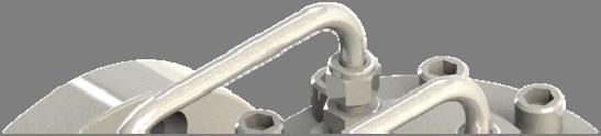
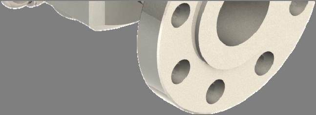
6 6 Dome Pressure Control The dome pressure of the regulator controls the outlet pressure. There are several methods available for supplying and controlling the dome pressure. - Integral pilot control. In this setup the dome-loaded regulator comes supplied with a pilot regulator as part of the assembly (Fig 1). The pilot regulator, fed from the system pressure, is manually operated to control the dome pressure (Fig 2). This setup is not suitable for liquid applications. - External dome control. In this setup the dome pressure is supplied from an independent source, such as a cylinder or main supply (Fig 3). This setup is suitable for liquid applications. - Electronic control. In this setup an electronic pilot regulator, fed from the system pressure, is used in conjunction with a pressure transducer to directly control the dome pressure (Fig 4). The outlet pressure of the main regulator will be limited by the outlet pressure of the electronic regulator. This setup is not suitable for liquid applications. - Ratio control. In this setup a ratio pilot regulator, fed from the system pressure, is used to control the dome pressure. The ratio pilot can be controlled by an electronic regulator and pressure transducer combination (Fig 5) or by an external dome feed. The ratio pilot outlet pressure is proportionally larger than its sensing pressure. This enables the main regulator to achieve full outlet pressure while being controlled from a low pressure supply. This setup is not suitable for liquid applications. The best performance will be achieved by allowing a small flow to continuously pass through the pilot regulator. This flow can either be vented through an orifice (Fig 3) or, in gas systems, fed back through an orifice into the downstream piping (Fig 2). This is usually referred to as dynamic regulation. NOTICE It is not recommended to place a gauge on the dome to set or check the outlet pressure. Because of forces in the regulator, the dome pressure will differ slightly from the outlet pressure. Place a gauge in the outlet line to set or check the outlet pressure. Integral Pilot Assembly Fig 1


7 7 Integral Pilot Control Schematic Pilot regulator Dynamic Regulation venting to the outlet line Dome regulator Fig 2 External Dome Control Schematic Pilot regulator Dynamic Regulation venting to atmosphere Dome regulator Cylinder or mains supply Fig 3

8 8 Electronic Control Schematic Electronic pilot regulator 4-20mA/0-10V 4-20mA/0-10V Pressure transducer Dome regulator Fig 4 Ratio Control Schematic Electronic pilot regulator 4-20mA/0-10V 4-20mA/0-10V Ratio regulator Pressure transducer Dome regulator Fig 5
9 9 External Feedback The purpose of external feedback is to provide a more accurate and stable regulation of the outlet pressure. This is achieved by sensing the outlet pressure downstream of the regulator and feeding it back to the regulator s sensing element. - The external feedback line is to be connected in a turbulence-free zone in the downstream piping, at a maximum distance of 5x the outside diameter of the downstream tubing/piping (Fig 6). - The tube size of the external feedback should be 3/8 in. or 1/2 in. or the metric equivalent. CAUTION When using a regulator with external feedback, ensure that the outlet line is connected to the external feedback port before applying pressure to the regulator. Failing to do so may lead to damage and non-functioning of the regulator and no pressure regulation will occur. CAUTION Never connect the external feedback line downstream of a shut-off valve. Doing so may lead to damage and non-functioning of the regulator and no pressure regulation will occur. External Feedback Schematic Dome pressure External feedback line Shutoff valve Shutoff valve O.D Inlet pressure Max. 5X O.D. Outlet pressure Fig 6
10 10 Operation Required Tools for Operation No tools are required for changing the set pressure on a standard regulator. Points of Attention Before Operation CAUTION The product can be hot or cold, depending on the environmental temperature and the process media temperature. Take the necessary precautions before operating or touching the product. - Stopping flow through the regulator by closing a downstream shutoff valve may result in a rise in outlet pressure above the set pressure. This is usually referred to as lock-up. This phenomenon does not indicate a problem with the regulator. - A decrease of the flow rate may result in a rise of the outlet pressure. An increase of the flow rate may result in a fall of the outlet pressure. This is usually referred to as droop. This phenomenon does not indicate a problem with the regulator. - A decrease of the inlet pressure may result in a rise of the outlet pressure. An increase of the inlet pressure may result in a fall of the outlet pressure. This is usually referred to as inlet dependency or Supply Pressure Effect (SPE). This phenomenon does not indicate a problem with the regulator. Adjusting the Set Pressure - The set pressure is the desired outlet pressure of the regulator. - To set the regulator, ensure that the supply pressure is greater than the required set pressure but does not exceed the maximum rating of the regulator. - The regulator must be able to flow in order for it to reduce the outlet pressure. 1. Partially open any downstream valve. This will allow minimal flow through the regulator when adjusting the set pressure, reducing media consumption during this process. 2. Ensure there is zero pressure in the dome. 3. Steadily open the supply valve to allow inlet pressure to the regulator. 4. To operate the regulator, turn the pilot adjustment knob clockwise to increase the set pressure. Turn the knob counterclockwise to reduce the set pressure. 5. To obtain the most accurate set pressure, final adjustment must be made while increasing the set pressure. If the desired outlet pressure is exceeded, reduce the pressure below this value then increase up to it. 6. Fully open the downstream valve to allow full flow during operation. 7. Once under flow conditions make any final set pressure adjustments per steps 3 and 4 if required. NOTICE The pilot regulator knob assembly is retained by a C-ring. When backing off the knob do not attempt to continue to unwind the knob once it has stopped. Doing so may damage the C-ring.


11 11 Maintenance WARNING Incorrect or improper repair or servicing of this product can cause serious personal injury and property damage. - All repairs, servicing, and testing of this product must be performed by competent personnel. - Following any maintenance of the regulator, it is recommended that the product be tested for operation and leakage. - The product should be checked periodically for proper and safe operation. It is the user s sole responsibility to determine the frequency of maintenance based on the application. - To reduce maintenance related system downtime to a minimum, either during commissioning or normal operation, Swagelok recommends having maintenance kits readily available on site. The need for maintenance kits is particularly important during the commissioning phase of a system installation due to residual assembly debris remaining in the system. Such debris can cause a seat leak in the regulator, resulting in components needing to be replaced. Required Tools for Maintenance Smooth-jawed vise Calibrated torque wrench up to 52 lbf ft (70 N m) 46 mm socket Appropriate open-ended wrenches for disassembling tube fittings Seat Mounting Tool RHPS-20-SEAT-TOOL RHPS-25-SEAT-TOOL Lubricant (included in kit) WL-8 1 Krytox 240 AC 2 10 mm hex drive Liquid leak detector C-ring pliers 1 Standard cleaned assemblies 2 ASTM G93 or SC11 cleaned assemblies Table 1
12 12 Points of Attention Before Removal from the System - Swagelok recommends removing the regulator from the system for servicing and maintenance. - Follow all local system safety and maintenance procedures when removing the regulator. WARNING Before removing a regulator from the system, to avoid personal injury, you must: Depressurize the system and dome. Purge the system to remove any residual system media left in the regulator. Always vent to a safe environment away from people and ensure there is adequate ventilation. CAUTION Check if the process media is hazardous or toxic. If required, take the necessary safety precautions to ensure a safe workspace and your personal safety. CAUTION The product can be hot or cold, depending on the environmental temperature and the process media temperature. Take the necessary precautions before operating or touching the product. Removal from the System 1. Isolate the regulator from all pressure sources by closing all appropriate upstream valves in the system. 2. With the pilot regulator set, open all appropriate downstream valves to allow pressure to vent from the regulator. WARNING Ensure all pressure on the inlet, outlet and dome has been fully vented. The accidental release of residual trapped pressure can cause serious personal injury. 3. Ensure appropriate lifting equipment is available to enable the regulator to be supported and handled once disconnected from the system. 4. Ensure that any external dome feed or external feedback connection is disconnected. 5. Disconnect and remove the regulator from the system.
13 13 Assembly Reference Data Item Component Name Kit Type(s) Torque Recommended Lubrication lbf ft (N m) (included in kit per Table 1) 1 Body plug C1, C2 52 (70) Lubricate threads 2 Body plug O-ring B1, B2, C1, C2 3 Poppet spring C1, C5 4 Poppet backup ring 1 A1, A2, B1, B2, C1 5 Poppet guide ring 2 B1, B2, C1, C2 6 Poppet O-ring A1, A2 1, B1, B2, C1, C2 2 Lubricate 7 Poppet A1, A2, B1, C1 RD(H)20-15 (20) 8 Seat A1, B1, C1 RD(H)25-18 (25) Lubricate threads 9 Seat O-ring A1, B1, B2, C1 10 Body N/A 11 Body plate C1 12 Body plate outer O-ring B1, B2, C1 13 Body plate inner O-ring B1, B2, C1 Lubricate 14 Retaining ring C1 15 Conical spring C1 16 Diaphragm plate C1 17 Diaphragm B1, B2, C1, C3 18 Dome plate N/A 19 Dome N/A 20 BSP blind plug O-ring B1, B2, C1 Wrap threads in 2 layers of NPT: 15 (20) 21 Blind plug N/A PTFE tape. Lubricate tape. BSP: 26 (35) Lubricate threads 22 Washer E1 23 Cap screw E1 52 (70) Lubricate threads 24 Parallel gasket B1, B2, C1 25 Bleed fitting (reduced orifice) N/A Per manufacturer instructions 26 Tube fitting N/A Per manufacturer instructions 27 Bleed tube N/A 28 Feed tube N/A 29 Pilot regulator N/A 30 Dome tube N/A 1 RD(H)20 series only 2 RD(H)25 series only Table 2 For more information on RHPS series maintenance kits, refer to the Pressure Regulators, RHPS Series catalog, MS
25")

14 14 RD(H)20, RD(H)25 Series Exploded View Fig 7


15 15 Integral Pilot Regulator Assembly Exploded View Fig 8


16 16 RDH20 Series, Standard, Section View Fig 9

17 17 RD25 Series, External Feedback, Section View Fig 10
18 18 Disassembly - The following instructions describe how to fully disassemble the regulator for the purposes of maintenance and repair. - Note that not all components listed appear in all regulator configurations. - Only disassemble the regulator as far as is required to replace the components supplied in the maintenance kit. - Discard all components being replaced. 1. If present remove the feed tube (28), dome tube (30), bleed tube (27), and pilot regulator (29). 2. Remove the body plug (1), poppet spring (3), and poppet (7) from the body (10). 3. Remove the body plug O-ring (2), poppet O-ring (6) and, if present, poppet backup ring (4) and guide ring (5) from the body plug (1) and poppet (6). 4. Using the seat insertion tool, remove the seat (8) and seat O-ring (9). 5. Remove the cap screws (23) to remove the dome (19), dome plate (18), diaphragm (17), and diaphragm plate (16). 6. Remove the retaining ring (14) to remove the body plate (11). For external feedback regulators remove the inner (13) and outer (12) body plate O-rings. Points of Attention Before Reassembly - Visually inspect all components for abnormal wear or damage. Replace components in case of doubt. - All parts must remain clean and undamaged before starting assembly. - Maintenance kit components will be supplied preassembled where practicable to aid reassembly. - Swagelok recommends replacing all O-rings removed during disassembly. - Swagelok recommends that dynamic O-rings should be lightly lubricated per Table 2. NOTICE All threaded components must be lightly lubricated per Table 2 before reassembly to avoid galling of threads.
19 19 Reassembly RD(H)20 Series: Standard 1. Fit the body plate (11) into the body (10) and retain with the retaining ring (14). 2. Fit the seat O-ring (9) into the body (10) and ensure that it is seated all the way round. 3. Lightly lubricate the seat threads (8) then insert the seat (8) into the body (10) using the seat insertion tool. Torque to 11 lbf ft (20 N m). Take care not to pinch the seat O-ring (9) or damage the seat (8) with the tool. 4. Fit the poppet O-ring (6) and, if present, backup ring (4) onto the poppet (7). Ensure they are oriented correctly per Fig Lightly lubricate the poppet O-ring (6) then insert the poppet (7) through the seat (8) and body plate (11). Take care not to damage either the seat (8) or poppet (7). 6. Place the poppet spring (3) into the poppet (7). 7. Fit the body plug O-ring (2) onto the body plug (1) and lightly lubricate the body plug threads. 8. Insert the body plug (1) into the body (10) over the poppet spring (3). Torque to 52 lbf ft (70 N m). 9. Place the diaphragm plate (16) onto the poppet (7). 10. Place the diaphragm (17) onto the diaphragm plate (16) and locate it in the body (10). 11. Place the dome plate (18) centrally onto the diaphragm (17) then cover with the dome (19). Orient the dome ports per Fig Lightly lubricate the cap screw threads (23) then use them and the washers (22) to secure the dome (19) to the body (10). Torque to 52 lbf ft (70 N m). 13. Install the feed tube (28), dome tube (30) and pilot regulator (29) into the ports on the inlet side of the body (10) per Fig Install the bleed tube (27) into the ports on the outlet side of the body (10) per Fig 8. Note that the bleed fitting (25) can be identified by its reduced internal orifice. 15. Make up all tube fittings (25, 26) per the manufacturers recommendations. RD(H)25 Series: Standard 1. Follow steps 1 and 2 of the RD(H)20 series standard reassembly procedure. 2. Lightly lubricate the seat threads (8) then insert the seat (8) into the body (10) using the seat insertion tool. Torque to 18 lbf ft (25 N m). Take care not to pinch the seat O-ring (9) or damage the seat (8) with the tool. 3. Fit the poppet O-ring (6) and guide ring (5) into the body plug (1). 4. Follow steps 5 through 15 of the RD(H)20 series standard reassembly procedure. RD(H)10 and RD(H)15 Series: External Feedback 1. Fit the inner (13) and outer (12) body plate O-rings onto the body plate (11). Lightly lubricate the inner body plate O-ring (13). 2. For size 20 regulators follow the RD(H)20 series standard reassembly procedure. 3. For size 25 regulators follow the RD(H)25 series standard reassembly procedure.
20 20 Testing Swagelok recommends that the regulator be tested for seat and shell leakage to atmosphere. A well performing regulator will not show any indication of leaking. If any evidence of a leak is identified this must be rectified. Any damaged components must be replaced. Seat Leak Test 1. Ensure there is sufficient supply pressure to the regulator to be able to perform the tests. 2. Ensure that there is zero pressure in the dome. 3. Maintain an inlet pressure of approximately 14.5 psig (1 bar) on the regulator and close the downstream shutoff valve. 4. Monitor the outlet pressure. An increase in pressure over time indicates a seat leak. 5. Repeat the procedure with the highest inlet pressure applicable for the regulator and system. Shell Leak Test 1. Maintain an inlet pressure of approximately 29 psig (2 bar) on the regulator and close the downstream shutoff valve. 2. Increase the outlet pressure to approximately 14.5 psig (1 bar). 3. Using liquid leak detector, check for bubbles at the dome to body interface and the body plug to body interface. 4. Repeat the procedure with the highest inlet and outlet pressure applicable for the regulator and system.
21 21 Troubleshooting Symptom Cause Remedy The outlet pressure creeps up, without adjusting dome pressure. A damaged poppet or seat. Replace the poppet and/or seat. Leakage around the body plug. A damaged O-ring. Replace the O-ring. Leakage between the body and the dome. Controlled pressure drops off sharply even when the flow is within regulator capabilities. The required outlet pressure cannot be reached. The outlet pressure rises too much when going from a dynamic to a static situation. The outlet pressure does not drop when the pressure in the dome is lowered. The outlet pressure has changed without adjusting the dome pressure. No pressure regulation occurs with an external feedback regulator. A damaged diaphragm. Insufficient torque on the cap screws. The system filter element is clogged. The inlet pressure to the regulator is not high enough. There is too much flow in the dynamic situation. The regulator is non-venting. Changes to the inlet pressure may result in changes to the outlet pressure. Changes to the flow may result in changes to the outlet pressure. The outlet line has not been connected to the external feedback port. Replace the diaphragm. Tighten the cap screws per Table 2. Replace the system filter. Ensure that the inlet pressure to the regulator is equal to or greater than the desired set pressure. A larger regulator or parallel regulator is required. Review application flow capacity and contact your local authorized sales and service center. A shutoff valve in the outlet line must be opened to reduce the outlet pressure. Maintain a constant inlet pressure to the regulator. See Points of Attention Before Operation about dependency. Maintain a constant flow through the regulator. See Points of Attention Before Operation about droop. Connect the outlet line to the external feedback port. See External Feedback for installation details. Table 3
22 22
23 23
24 Warranty Information Swagelok products are backed by The Swagelok Limited Lifetime Warranty. For a copy, visit swagelok.com or contact your authorized Swagelok representative. Swagelok, Snoop - TM Swagelok Company Krytox TM The Chemours Company 2018 Swagelok Company March 2018, Rev B MS-CRD-0182
LRS(H)4 Pressure-Reducing Regulator User Manual
4 Pressure-Reducing Regulator User Manual") LRS(H)4 Pressure-Reducing Regulator User Manual Read the complete manual before installing and using the regulator. 2 Safe Product Selection When selecting a product, the total system design must be considered
LRS(H)4 Pressure-Reducing Regulator User Manual Read the complete manual before installing and using the regulator. 2 Safe Product Selection When selecting a product, the total system design must be considered
RHPS Series RD(H)F40 User Manual. Read the complete manual before installing and using the regulator.
F40 User Manual. Read the complete manual before installing and using the regulator.") RHPS Series RD(H)F40 User Manual Read the complete manual before installing and using the regulator. 2 WARNING Before removing a regulator from the system for service, you must depressurize system purge
RHPS Series RD(H)F40 User Manual Read the complete manual before installing and using the regulator. 2 WARNING Before removing a regulator from the system for service, you must depressurize system purge
RS(H)10,15 USER MANUAL. Read the complete manual before installing and using the regulator.
10,15 USER MANUAL. Read the complete manual before installing and using the regulator.") RS(H)10,15 USER MANUAL Read the complete manual before installing and using the regulator. WARNING INCORRECT OR IMPROPER USE OF THIS PRODUCT CAN CAUSE SERIOUS PERSONAL INJURY AND PROPERTY DAMAGE. Due to
RS(H)10,15 USER MANUAL Read the complete manual before installing and using the regulator. WARNING INCORRECT OR IMPROPER USE OF THIS PRODUCT CAN CAUSE SERIOUS PERSONAL INJURY AND PROPERTY DAMAGE. Due to
LRS(H)4 USER MANUAL. Read the complete manual before installing and using the regulator.
4 USER MANUAL. Read the complete manual before installing and using the regulator.") LRS(H)4 USER MANUAL Read the complete manual before installing and using the regulator. WARNING INCORRECT OR IMPROPER USE OF THIS PRODUCT CAN CAUSE SERIOUS PERSONAL INJURY AND PROPERTY DAMAGE. Due to the
LRS(H)4 USER MANUAL Read the complete manual before installing and using the regulator. WARNING INCORRECT OR IMPROPER USE OF THIS PRODUCT CAN CAUSE SERIOUS PERSONAL INJURY AND PROPERTY DAMAGE. Due to the
PRS(TC)4,8 USER MANUAL. Read the complete manual before installing and using the regulator.
4,8 USER MANUAL. Read the complete manual before installing and using the regulator.") PRS(TC)4,8 USER MANUAL Read the complete manual before installing and using the regulator. WARNING INCORRECT OR IMPROPER USE OF THIS PRODUCT CAN CAUSE SERIOUS PERSONAL INJURY AND PROPERTY DAMAGE. Due to
PRS(TC)4,8 USER MANUAL Read the complete manual before installing and using the regulator. WARNING INCORRECT OR IMPROPER USE OF THIS PRODUCT CAN CAUSE SERIOUS PERSONAL INJURY AND PROPERTY DAMAGE. Due to
RS(H)20, 25 USER MANUAL
20, 25 USER MANUAL") RS(H)20, 25 USER MANUAL Read the complete manual before installing and using the regulator. WARNING Before removing a regulator from the system for service, you must depressurize system purge the system
RS(H)20, 25 USER MANUAL Read the complete manual before installing and using the regulator. WARNING Before removing a regulator from the system for service, you must depressurize system purge the system
RHPS Series PRV 6 User Manual
 RHPS Series PRV 6 User Manual Read the complete manual before installing and using the valve. 1 WARNING Before removing a valve from the system for service, you must depressurize system purge the system
THE HF-300 SERIES. Operating and Service Manual. Series includes all variants of HF-300/301
 THE HF-300 SERIES Operating and Service Manual Series includes all variants of HF-300/301 Issue A July 2015 1 TABLE OF CONTENTS 1. Description... 3 2. Installation... 3 3. Operation... 4 3.1. Spring Loaded...
Tank Blanketing Pressure Regulators RHPS Series
 www.swagelok.com Tank Blanketing Pressure Regulators RHPS Series Types: pressure reducing and vapor recovery 16L stainless steel construction 1/2, 1, and 2 in. end connections Working pressures up to 22
Pressure Regulators. Operating Instructions. Instrumentation
 Pressure Regulators Operating Instructions FAILURE OR IMPROPER SELECTION OR IMPROPER USE OF THIS PRODUCT CAN CAUSE DEATH, PERSONAL INJURY AND PROPERTY DAMAGE. This document and other information from the
THE BP-301 SERIES. Operating and Service Manual. Series includes all variants of BP-301 (LF 0.1Cv / MF 0.5Cv)
") THE BP-301 SERIES Operating and Service Manual Series includes all variants of BP-301 (LF 0.1Cv / MF 0.5Cv) Issue B October 2015 1 TABLE OF CONTENTS 1. Description... 3 2. Installation... 3 3. Operation...
THE BP-301 SERIES Operating and Service Manual Series includes all variants of BP-301 (LF 0.1Cv / MF 0.5Cv) Issue B October 2015 1 TABLE OF CONTENTS 1. Description... 3 2. Installation... 3 3. Operation...
THE MF-400 SERIES. Operating and Service Manual. Series includes all variants of MF-400/401
 THE MF-400 SERIES Operating and Service Manual Series includes all variants of MF-400/401 Issue A October 2013 1 TABLE OF CONTENTS 1. Description... 3 2. Installation... 3 3. Operation... 4 4. Special
INSTALLATION, OPERATION, AND MAINTENANCE MANUAL WELKER RELIEF VALVE
 INSTALLATION, OPERATION, AND MAINTENANCE MANUAL WELKER RELIEF VALVE MODELS RV-1 RV-2 RV-2CP RV-3 DRAWING NUMBERS AD017A[ ] AD018A[ ] AD020A[ ] AD282BO MANUAL NUMBER IOM-033 REVISION Rev. E, 3/28/2016 TABLE
THE BP-690 SERIES. Operating and Service Manual. Series includes all variants of BP-LF/MF-690/691
 THE BP-690 SERIES Operating and Service Manual Series includes all variants of BP-LF/MF-690/691 Issue B April 2015 1 TABLE OF CONTENTS 1. Description... 3 2. Installation... 3 3. Operation... 4 4. Special
RHPS Series PRV 2 all types of connections User Manual
 RHPS Series PRV 2 all types of connections User Manual Read the complete manual before installing and using the valve. Before removing a valve from the system for service, you must depressurize system
Operation Manual Piston Sensed Gas Pressure Regulators
 687 Technology Way Napa, CA 94558 Phone: (707) 259-0102 FAX: (707) 259-0117 www.aptech-online.com Operation Manual Piston Sensed Gas Pressure Regulators (Models KT9, KT10, Welded KT10, KT12) Table of Contents:
Installation Troubleshooting Maintenance Instructions Installation / Start-up
 Model ZW207 Installation Troubleshooting Maintenance Instructions Installation / Start-up NOTE: Flushing of all pipe lines is to be performed to remove all debris prior to installing valve. 1. For making
Welker Sampler. Model GSS-1. Installation, Operation, and Maintenance Manual
 Installation, Operation, and Maintenance Manual Welker Sampler Model GSS-1 The information in this manual has been carefully checked for accuracy and is intended to be used as a guide to operations. Correct
Installation, Operation and Maintenance Manual for Back Pressure Regulator
 Installation, Operation and Maintenance Manual for Back Pressure Regulator Model 8860 2009 Groth Corporation IOM-8860 Rev. B 12541 Ref. ID: 95565 Page 2 of 13 Table of Contents I. INTRODUCTION 3 II. DESIGN
Operation Manual. Diaphragm Sensed Gas Pressure Regulators
 687 Technology Way Napa, CA 94558 Phone: (707) 259-0102 FAX: (707) 259-0117 www.aptech-online.com Diaphragm Sensed Gas (AP/AZ/AK Models: 20, 100, 500, 1000, 1000T 10PA, 1100, 1200, 12PA, 1300, 1400T, 14PA,
MEGR-1912 Instruction Manual
 MEGR-1912 PRESSURE REGULATOR Instruction Manual- Look Inside For: Description Installation Start-Up Maintenance Parts Ordering Parts List Marshall Excelsior Company Marshall, MI 49068 269-789-6700 FAX
Installation, Operation, and Maintenance Manual
 Installation, Operation, and Maintenance Manual Welker The information in this manual has been carefully checked for accuracy and is intended to be used as a guide for the installation, operation, and
1200B2 Series Service Regulators. Instruction Manual
 00B Series Service Regulators Instruction Manual 00B Series Service Regulators 0 Elster American Meter 00B Series Service Regulators General Information The 00B Series Service Regulators are available
Bermad Pressure Reducing. Model: 42T
 Bermad Pressure Reducing Pilot Operated Pressure Control Valve Model: 42T Installation Operation Maintenance Manual (IOM) REV. 27.7.17 Page 1 of 12 Safety First BERMAD believes that the safety of personnel
Operating Manual. R280 Pressure regulator made of brass. 1. Intended Use
 Pressure regulator made of brass Operating Manual 1. Intended Use Line or outlet pressure regulators- /reducer for Air, gases and liquids which is designed to effect reduction to a downstream pressure
Product Manual. Description. Specifications. CVS Type 1301F and CVS Type 1301G Regulator. Introduction
 Product Manual CVS Type 1301F and CVS Type 1301G Regulator Introduction This CVS Controls product manual includes instructions for the installation, adjustment, maintenance and parts ordering of the CVS
64 Series Pressure Reducing Regulators
 Instruction Manual Form 1245 64 Series March 2006 64 Series Pressure Reducing Regulators W1943 Figure 1. 64 Series Regulator Introduction Scope of Manual This manual provides instructions for the installation,
1800C and 1800C-HC Series Service Regulators
 1800C and 1800C-HC Series Service Regulators Installation Instructions www.elster-americanmeter.com General Information: The 1800C and 1800C-HC Regulators are available as Full Capacity Internal Relief
MEGR-1627 Instruction Manual
 MEGR-1627 HIGH FLOW GAS REGULATOR Instruction Manual- Look Inside For: Description Installation Remote Vent Line Installations Startup and Adjustment Shutdown Maintenance Body Maintenance Procedures Diaphragm
Types PT and ETP Dome-Loaded Pressure Regulator Valves
 1BInstallation, Operation, and Maintenance Manual Types PT and ETP Dome-Loaded Pressure Regulator Valves 58 0BINSTRUCTIONS FOR TYPE PT REGULATORS 2BCAUTIONARY NOTE It is important that the correct start-up
Installation, Operation, and Maintenance Manual
 Installation, Operation, and Maintenance Manual Welker Probe Instrument Regulator Model The information in this manual has been carefully checked for accuracy and is intended to be used as a guide for
Model GP PRESSURE REDUCING VALVE Installation & Operation Manual
 Model GP-2000 PRESSURE REDUCING VALVE Installation & Operation Manual Please read this bulletin thoroughly before using the pressure reducing valve, so that you may do so correctly and safely. Please carefully
TECHNICAL DATA. Page 1 of 12
 Page 1 of 12 1. DESCRIPTION The Viking Regulating Valve is a direct-acting, single-seated, spring-loaded diaphragm valve. When installed as a pilot regulating valve on a Viking Model H or J Flow Control
INSTALLATION, OPERATION, AND MAINTENANCE MANUAL WELKER FILTER DRYER
 INSTALLATION, OPERATION, AND MAINTENANCE MANUAL WELKER FILTER DRYER MODEL F-4 DRAWING NUMBERS AD042C[ ] AD054C[ ] MANUAL NUMBER IOM-046 REVISION Rev. F, 4/23/2018 TABLE OF CONTENTS SAFETY 3 1. PRODUCT
DC5A. Cyclone Separator Trap for Air. Copyright 2015 by TLV Co., Ltd. All rights reserved ISO 9001/ ISO MA-03 (DC5A) 19 June 2015
 19 June 2015") 172-65205MA-03 (DC5A) 19 June 2015 ISO 9001/ ISO 14001 Manufacturer Kakogawa, Japan is approved by LRQA LTD. to ISO 9001/14001 Cyclone Separator Trap for Air DC5A Copyright 2015 by TLV Co., Ltd. All rights
172-65205MA-03 (DC5A) 19 June 2015 ISO 9001/ ISO 14001 Manufacturer Kakogawa, Japan is approved by LRQA LTD. to ISO 9001/14001 Cyclone Separator Trap for Air DC5A Copyright 2015 by TLV Co., Ltd. All rights
Installation, Operation, and Maintenance Manual. Welker Constant Pressure Cylinder With Welker Magnetic Indicator (With Gravity Mixer) Model CP2GM-HP
 Model CP2GM-HP") Installation, Operation, and Maintenance Manual Welker Constant Pressure Cylinder With Welker Magnetic Indicator (With Gravity Mixer) Model The information in this manual has been carefully checked for
Installation, Operation, and Maintenance Manual Welker Constant Pressure Cylinder With Welker Magnetic Indicator (With Gravity Mixer) Model The information in this manual has been carefully checked for
INSTALLATION INSTRUCTIONS. CVS 67CFR Pressure Reducing Instrument Supply Regulator INTRODUCTION
 INSTALLATION INSTRUCTIONS CVS 67CFR Pressure Reducing Instrument Supply Regulator INTRODUCTION The CVS Controls 67CFR Filter regulator is a pressure reducing supply regulator typically used for pneumatic
Model Secure-Gard Pilot Operated Vent Valve SECTION II. Remove all packing material inside and outside of the valve prior to installation.
 INSTALLATION, OPERATION AND MAINTENANCE MANUAL (IOM) IOM - 1049 01-17 Model 1049 Secure-Gard Pilot Operated Vent Valve ISO Registered Company SECTION I I. DESCRIPTION AND SCOPE The Model 1049 Secure-Gard
THE HF-210 SERIES. Operating and Service Manual. Series includes all variants of HF-210/211. Issue A October 2014 *Section 6.
 THE HF-210 SERIES Operating and Service Manual Series includes all variants of HF-210/211 Issue A October 2014 *Section 6.1 in development 1 TABLE OF CONTENTS 1. Description... 3 2. Installation... 3 3.
INSTALLATION, OPERATION, AND MAINTENANCE MANUAL WELKER COMPOSITE GAS SAMPLER
 INSTALLATION, OPERATION, AND MAINTENANCE MANUAL WELKER COMPOSITE GAS SAMPLER MODEL GSS-4PM DRAWING NUMBERS AD617BS AD617CL MANUAL NUMBER IOM-022 REVISION Rev. E, 6/8/2017 TABLE OF CONTENTS SAFETY 3 1.
Installation Operation Maintenance. Bermad Level Control Valve with Modulating Horizontal Float Pilot valve One Way Flow IOM.
 Bermad Level Control Valve with Modulating Horizontal Float Pilot valve One Way Flow Model: FP 450-80 Installation Operation Maintenance PAGE 1 OF 5 1. Safety First BERMAD believes that the safety of personnel
TECHNICAL DATA. Pressure Regulation 531a. April 24, 2009
 April 24, 29 Pressure Regulation 531a 1. DESCRIPTION The Viking Regulating Valve is a direct-acting, single-seated, spring-loaded diaphragm valve. When installed as a pilot regulating valve on a Viking
INSTALLATION, OPERATION, AND MAINTENANCE MANUAL WELKER CONSTANT PRESSURE CYLINDER
 INSTALLATION, OPERATION, AND MAINTENANCE MANUAL WELKER CONSTANT PRESSURE CYLINDER MODEL CP-11 DRAWING NUMBERS AD157CO AD157CP.CE MANUAL NUMBER IOM-184 REVISION Rev. B, 6/7/2018 TABLE OF CONTENTS SAFETY
Regulator from 1800 B series
 Regulator from 1800 B series Regulator from 1800 B series Measuring of industrial gases frequently requests a precise pressure regulation for the purpose of dosage and proccesing. UNIS FAGAS has two kinds
Anderson Greenwood Series 93 Positive Pressure POSRV Installation and Maintenance Instructions
 Before installation these instructions must be fully read and understood Installation and maintenance instructions for Series 93 Positive Pressure Pilot Operated Safety Relief Valves (POSRV). The intent
TESCOM 50-4X Series Safety, Installation & Start-Up Procedures
 Operations & Service Manual TESCOM 50-4X Series Safety, Installation & Start-Up Procedures Do not attempt to select, install, use or maintain this product until you have read and fully understood this
FILTER REGULATORS MODEL NO: CAT155 & CAT156 FITTING & MAINTENANCE INSTRUCTIONS PART NO: & ORIGINAL INSTRUCTIONS
 FILTER REGULATORS MODEL NO: CAT155 & CAT156 PART NO: 3120169 & 3120170 FITTING & MAINTENANCE INSTRUCTIONS ORIGINAL INSTRUCTIONS GC0117 INTRODUCTION Thank you for purchasing this CLARKE Filter/Regulator.
Anderson Greenwood Series 400 Diaphragm Pilot Operated Safety Relief Valves. Installation and Maintenance Instructions for
 Before installation these instructions must be fully read and understood The main valve uses the principle of pressurizing the top or large area of a differential area piston with line pressure to hold
Type ACE97. Introduction. Installation. P.E.D. Categories. Specifications. Overpressure Protection. Installation Guide English May 2002
 Installation Guide English May 2002 Type ACE97 Introduction This installation guide provides instructions for installation, startup, and adjustment. To receive a copy of the instruction manual, contact
WHEATLEY WHEATLEY SERIES 500 SWING CHECK VALVE. Installation, Operation and Maintenance Manual
 WHEATLEY SERIES 500 SWING CHECK VALVE STANDARD INTEGRAL SEAT & OPTIONAL REMOVABLE SEAT 2" FP - 6" FP 150# - 1500# 8" FP - 12" FP 150# - 900# API 6D and B16.34 2" FP - 4" FP 5000# DRILLING PRODUCTION VALVE
Mounting and operating instructions EB 2530 EN. Self-operated Pressure Regulator. Pressure Reducing Valve Type M 44-2
 Self-operated Pressure Regulator Pressure Reducing Valve Type M 44-2 Type M 44-2, connection G 1 4, K VS = 0.15 Type M 44-2, connection G 1, K VS = 6 Fig. 1 Type M 44-2 Pressure Reducing Valve Mounting
Propor tional Re lief Valve s
 www.swagelok.com Propor tional Re lief Valve s R Series Liquid or gas service Set pressures from 10 to 6000 psig (0.68 to 413 bar) 1/4 and 1/2 in. and 6 to 12 mm end connections Proportional Relief Valves
INDUSTRIAL VALVES MODELS: C62-A; C62-D. INSTRUCTION MANUAL Installation Operation Parts Service DIAPHRAGM BYPASS PRESSURE REGULATING VALVES
 INSTRUCTION MANUAL Installation Operation Parts Service IMPORTANT Record your Regulator model number and serial number here for easy reference: Model No. Serial No. Date of Purchase When ordering parts
Model: 720-UL INSTALLATION OPERATION MAINTENANCE. Bermad Pressure Reducing Valve IOM. Model: FP -720-UL Sizes: 2"-12" BERMAD. Application Engineering
 Bermad Pressure Reducing Valve Model: 720-UL INSTALLATION OPERATION MAINTENANCE Application Engineering BERMAD 1. Safety First BERMAD believes that the safety of personnel working with and around our equipment
AIR DISTRIBUTOR. PART NUMBER (Including, but not inclusive) AD28483-_ALB, AD28563-_ALB, AD36097-_ALB, AD36098-_ALB, AD28485-_ALB
 AD28483-_ALB, AD28563-_ALB, AD36097-_ALB, AD36098-_ALB, AD28485-_ALB") Manual #: MM-AD001 12/5/11 Rev. A Page 1 of 8 PART NUMBER (Including, but not inclusive) AD28483-_ALB, AD28563-_ALB, AD36097-_ALB, AD36098-_ALB, AD28485-_ALB Manual #: MM-AD001 12/5/11 Rev. A Page 2 of
Manual #: MM-AD001 12/5/11 Rev. A Page 1 of 8 PART NUMBER (Including, but not inclusive) AD28483-_ALB, AD28563-_ALB, AD36097-_ALB, AD36098-_ALB, AD28485-_ALB Manual #: MM-AD001 12/5/11 Rev. A Page 2 of
299H Series. Introduction. P.E.D. Categories. Specifications. Installation. Warning. Installation Guide English September 2012
 Installation Guide English September 2012 299H Series Introduction This Installation Guide provides instructions for installation, startup, and adjustment of 299H Series regulators. To receive a copy of
Proportional Relief Valves
 www.swagelok.com Proportional Relief Valves R Series Liquid or gas service Set pressures from 10 to 6000 psig (0.68 to 413 bar) 1/4 and 1/2 in. and 6 to 12 mm end connections 2 Proportional Relief Valves
WHEATLEY Series 822/820 Swing Check Valve
 Document Number: TC003001-12 Revision: 02 WHEATLEY Series 822/820 Swing Check Valve Installation, Operation, and Maintenance Manual TABLE OF CONTENTS BILL OF MATERIALS...3 SCOPE...4 INSTALLATION AND OPERATION
Model VR6 System. Installation, Operation & Maintenance
 Model VR6 System Installation, Operation & Maintenance General: All Archer Instruments chlorination systems are carefully designed and tested for years of safe, accurate field service. All Archer Instruments
Model: 43T. Bermad Pressure Relief Valve
 Model: 43T Bermad Pressure Relief Valve Installation Operation Maintenance Manual () Rev.C1_01.08.17 Page 1 of 10 Safety First BERMAD believes that the safety of personnel working with and around our equipment
DS05C,D,G Dial Set Pressure Regulating Valves
 DS05C,D,G Dial Set Pressure Regulating Valves APPLICATION The Honeywell DS05C,D,G Dial Set Pressure Regulating Valve is a high quality pressure regulating valve that maintains a constant outlet pressure
TECHNICAL DATA CAUTION
 Page 1 of 12 1. DESCRIPTION The Viking Model C-2 Pilot Pressure Regulating Valve is a direct-acting, single-seated, spring-loaded diaphragm valve. When installed as a pilot regulating valve on a Viking
Binks SG-2 Plus TM Rotary 2 QT. PRESSURE CUP
 Binks SG-2 Plus TM Rotary 2 QT. PRESSURE CUP Model No. 80-651 Rotary Agitator INTRODUCTION Binks SG-2 TM Plus Rotary 2 Qt. Pressure Cup is ideal for component spraying and industrial applications where
DS06D,G Dial Set Pressure Regulating Valve
 DS06D,G Dial Set Pressure Regulating Valve PRODUCT DATA FEATURES APPLICATION Built-in, factory-calibrated outlet pressure adjustment dial. Noncorroding unitized cartridge contains all working parts and
Installation Operating Instructions for Simple Duplex Manual Manifolds PX-TSD Series
 Introduction Powerex manifolds are cleaned, tested and prepared for the indicated gas service and are built in accordance with the Compressed Gas Association guidelines. The manifold consists of a regulator
PN-DR. Pneumatic Direct-acting Pressure Reducing Valve for Steam and Air. Copyright 2018 by TLV CO., LTD. All rights reserved
 172-65519MA-03 () 24 January 2018 Pneumatic Direct-acting Pressure Reducing for Steam and Air Copyright 2018 by TLV CO., LTD. All rights reserved 1 Contents Contents... 1 Introduction... 1 Safety Considerations...
NB/NBR NITROGEN BOOSTER FOR AVIATION SERVICE
 NB/NBR NITROGEN BOOSTER FOR AVIATION SERVICE INSTALLATION, OPERATION & MAINTENANCE MANUAL INTERFACE DEVICES, INC. 230 Depot Road, Milford, CT 06460 Ph: (203) 878-4648, Fx: (203) 882-0885, E-mail: info@interfacedevices.com
Installation, Operation, and Maintenance Manual
 Installation, Operation, and Maintenance Manual Welker Constant Pressure Cylinder With Welker Magnetic Indicator (Non-mixer) Model The information in this manual has been carefully checked for accuracy
Models: C62/63/64-A/D
 Installation & Service C62-991-24A3 Models: C62/63/64-A/D Diaphragm Bypass Pressure Regulating Valves IMPORTANT Record your pump model number and serial number here for easy reference: Model No. Serial
WHEATLEY Series 500 Swing Check Valve
 Document Number: TC003001-13 Revision: 02 WHEATLEY Series 500 Swing Check Valve Installation, Operation, and Maintenance Manual TABLE OF CONTENTS BILL OF MATERIALS...3 SCOPE...5 INSTALLATION AND OPERATION
Mooney* FlowMax* Regulator
 GE Oil & Gas Mooney* FlowMax* Regulator Instruction Manual (Rev. A) GE Data Classification : Public THESE INSTRUCTIONS PROVIDE THE CUSTOMER/OPERATOR WITH IMPORTANT PROJECT- SPECIFIC REFERENCE INFORMATION
Model GPR Primary Pressure Regulating Valve. Instruction Manual
 Model GPR-2000 Primary Pressure Regulating Valve Instruction Manual Please read this instruction manual thoroughly before using the primary pressure regulating valve, so that you may do so correctly and
Installation, Operation, and Maintenance Manual. Welker Constant Pressure Cylinder With Solid Indicator (Non-mixer) Model CP-30SI
 Model CP-30SI") Installation, Operation, and Maintenance Manual Welker Constant Pressure Cylinder With Solid Indicator (Non-mixer) Model The information in this manual has been carefully checked for accuracy and is intended
Installation, Operation, and Maintenance Manual Welker Constant Pressure Cylinder With Solid Indicator (Non-mixer) Model The information in this manual has been carefully checked for accuracy and is intended
Service and Repair Manual
 II stage R2 Ice/ Special, II stage R 1 Pro DOWNSTREAM 2 nd STAGE REGULATOR Service and Repair Manual Introduction Safety Precautions...4 General Procedures, Maintenance Schedules...5 Initial Inspection
Automatic Non-freeze Valve NF6
 172-65134MA-03 (NF6) 30 March 2015 ISO 9001/ ISO 14001 Manufacturer Kakogawa, Japan is approved by LRQA LTD. to ISO 9001/14001 Automatic Non-freeze Valve NF6 Copyright 2015 by TLV CO., LTD. All rights
D05 Pressure Regulating Valves
 D05 Pressure Regulating Valves FEATURES PRODUCT DATA Noncorroding unitized cartridge contains all working parts and is easily replaceable. Includes built-in strainer and thermal bypass. Balanced seat construction
INSTALLATION, MAINTENANCE & OPERATING INSTRUCTIONS 2-4 REDUCED PORT/ FULL PORT (5700/6700) ANSI CLASS 150/300/600/900/1500/2500 TRUNNION BALL VALVES
 ANSI CLASS 150/300/600/900/1500/2500 TRUNNION BALL VALVES") PBV-USA,Inc. 12735 Dairy Ashford. Stafford, Texas USA 77477 281-340-5400; 800-256-6193 FAX: 281-340-5499 INDUSTRIAL BALL VALVES IM0 69 April 2001 Rev 9 INSTALLATION, MAINTENANCE & OPERATING INSTRUCTIONS
PBV-USA,Inc. 12735 Dairy Ashford. Stafford, Texas USA 77477 281-340-5400; 800-256-6193 FAX: 281-340-5499 INDUSTRIAL BALL VALVES IM0 69 April 2001 Rev 9 INSTALLATION, MAINTENANCE & OPERATING INSTRUCTIONS
Type S301 & S302 Gas Regulators INTRODUCTION INSTALLATION. Scope of Manual. Description. Specifications. Type S301 and S302. Instruction Manual
 Fisher Controls Instruction Manual Type S301 & S302 Gas Regulators October 1981 Form 5180 WARNING Fisher regulators must be installed, operated, and maintained in accordance with federal, state, and local
GS/GSD Series Precision Back Pressure Regulator
 Use and Startup Warning: Make sure that you have read and understand these directions before using, installing, or maintaining the Equilibar pressure regulator. Take steps to ensure this instruction manual
Types S100K and S102K Pressure Regulators
 Instruction Manual Form 5624 Types S0K and S2K 01/01 Types S0K and S2K Pressure Regulators W7478-1 Figure 1. Types S0K and S2K Pressure Regulator Introduction Scope of Manual This manual provides instructions
P5513. Users Manual. Pneumatic Comparison Test Pump. Test Equipment Depot Washington Street Melrose, MA TestEquipmentDepot.
 Test Equipment Depot - 800.517.8431-99 Washington Street Melrose, MA 02176 TestEquipmentDepot.com P5513 Pneumatic Comparison Test Pump Users Manual PN 3963372 November 2010 2010 Fluke Corporation. All
Assembly Drawing: W-311B-A01, or as applicable Parts List: W-311B-A01-1, or as applicable Special Tools: , , &
 REDQ Regulators Model 411B Barstock Design Powreactor Dome Regulator OPERATION AND MAINTENANCE Contents Scope..............................1 Installation..........................1 General Description....................1
Carter Option X Valve connector assembly. Maintenance manual
 Carter Option X Valve connector assembly Maintenance manual Table of contents Description Page 1.0 Introduction... 3 1.1 Safety equipment and procedure... 3 1.2 Maintenance safety alerts... 3 2.0 Equipment
Helium-Oxygen Blender
 Helium-Oxygen Blender Service Manual Model No. PM5400 Series PM5500 Series (shown) SAVE THESE INSTRUCTIONS 300 Held Drive Tel: (+001) 610-262-6090 Northampton, PA 18067 USA Fax: (+001) 610-262-6080 www.precisionmedical.com
I T T Pressure Reducing Valve WARNING INSTALLATION, OPERATION, AND MAINTENANCE MANUAL
 INSTALLATION, OPERATION, AND MAINTENANCE MANUAL I-867-4T 867-4T Pressure Reducing Valve HANG THESE INSTRUCTIONS ON THE INSTALLED VALVE FOR FUTURE REFERENCE WARNING Read and understand all instructions
A-DR20-2/A-DR20-6/A-DR20-10
 172-65634MA-00 () 23 July 2015 ISO9001/ISO14001 Manufacturer Kakogawa, Japan is approved by LRQA LTD. to ISO 9001/14001 Direct-acting Pressure Reducing for Air -2/-6/-10 Copyright 2015 by TLV CO., LTD.
Combination Air Valve
 Combination Air Valve For Sewage and Wastewater Model C50 Installation, Operation and Maintenance Manual (IOM) Table of Contents General... Page 2 Safety... Page 2 Operational Data... Page 3 Materials
OPERATION MANUAL NTF-15
 OPERATION MANUAL NTF-15 Nitrogen Tire Filling Valve Stem Caps (Qty=200) Order P/N 436075 RTI Technologies, Inc 10 Innovation Drive York, PA 17402 800-468-2321 www.rtitech.com 035-81235-00 (Rev B) TABLE
Mooney * Noise Controller Installation, Operation, and Maintenance Manual
 GE Oil & Gas Mooney * Noise Controller Installation, Operation, and Maintenance Manual imagination at work Scope This manual provides instructions for installation, operation and maintenance of the Mooney
Float Operated Level Controllers
 CONTENTS Float Operated Level Controllers IM0015 Nov. 2014 PAGE Introduction 1 Scope 1 Description 1 Specification 1 Control Installation 2 INTRODUCTION Side Mount Back Mount Prior to installing, the instructions
V DGX Series. Direct-Operated Regulators Manual D103834X012
 V2015.3 DGX Series Direct-Operated Regulators Manual D103834X012 Contents 1. Introduction... 3 2. Specifications... 3 3. Features... 3 4. Dimensions... 4 5. Principle of Operation... 5 6. Performance Curves...
TECHNICAL DATA CAUTION
 Page 1 of 6 1. DESCRIPTION The Viking Model D-2 Accelerator is a quick-opening device, with an integral anti-flood assembly, used to increase the operating speed of a differential type dry pipe valve.
Spiratec ST14, ST16 and ST17 Sensor Chambers and sensors
 0862050/1 IM-P086-18 MI Issue 1 Spiratec ST14, ST16 and ST17 Sensor Chambers and sensors Installation and Maintenance Instructions 1. Safety Information 2. General product information 3. Installation 4.
1301 Series High-Pressure Regulators
 Instruction Manual Form 1111 Types 1301F and 1301G March 2013 1301 Series High-Pressure Regulators! WARNING Failure to follow these instructions or to properly install and maintain this equipment could
Type CT88 Backpressure Regulator
 Instruction Manual Type CT88 July 2016 Type CT88 Backpressure Regulator Table of Contents Introduction...1 Specifications...2 Principle of Operation...2 Installation...3 Overpressure Protection...4 Startup...4
OPERATING AND MAINTENANCE MANUAL
 Series 4300 Engineered Performance TABLE OF CONTENTS 0 INTRODUCTION 1 1 Scope 1 2 Description 1 3 Specifications 1 0 INSTALLATION 1 1 Mounting 1 2 Piping 1 1 Connecting Process Pressure 2 2 Vent Connections
Pressure Reducing Valve for Air A-COS-10
 172-65254MA-03 (-10) 26 June 2015 ISO 9001/ ISO 14001 Manufacturer Kakogawa, Japan is approved by LRQA LTD. to ISO 9001/14001 Pressure Reducing for Air -10 Copyright 2015 by TLV CO., LTD. All rights reserved
Installation Instructions and valve Maintenance Rev. 0 of 21/09/15
 ASSEMBLING PROCEDURE AND VALVE MAINTENANCE 1.0.... Safety Information 2.0.. INTRODUCTION 3.0 VARIATIONS 4.0..ASSEMBLING PROCEDURE FOR THE STEM 5.0 ASSEMBLING PROCEDURE FOR OUTLET CONNECTIONS 6.0 PROCEDURE
VALVES & MEASUREMENT
 VALVES & MEASUREMENT TBV OPERATION AND MAINTENANCE MANUAL SERIES 1100: THREE PIECE BALL VALVE For technical questions, please contact the following: Engineering Department 1537 Grafton Road Millbury, MA
Constant Pressure Crude Oil Container Model CPCCP
 Installation, Operations, and Maintenance Manual Constant Pressure Crude Oil Container Model CPCCP The information in this manual has been carefully checked for accuracy and is intended to be used as a