7 Flumes. 7.1 Long-throated flumes Description
|
|
|
- Imogen Wilkinson
- 6 years ago
- Views:
Transcription
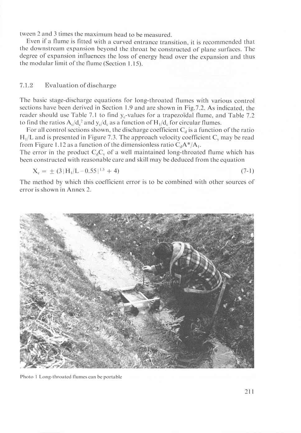
1 7 Flumes A critical depth-flume is essentially a geometrically specified constriction built in an open channel where sufficient fall is available for critical flow to occur in the throat of the flume. Flumes are in-line structures, i.e. their centre line coincides with the centre line of the undivided channel in which the flow is to be measured. The flume cannot be used in structures like turnouts, controls and other regulating devices. In this chapter the following types of critical-depth flumes will be described: Longthroated flumes (7. I), Throatless flumes with rounded transition (7.2), Throatless flumes with broken plane transition (7.3), Parshall flumes (7.4), H-flumes (7.5). The name Venturi flume is not used in this chapter, since this term is reserved for flumes in which flow in the constriction is sub-critical. The discharge through such a constriction can be calculated by use of the equations presented in Section Long-throated flumes Description Classified under the term long-throated flumes are those structures which have a throat section in which the streamlines run parallel to each other at least over a short distance. Because of this, hydrostatic pressure distribution can be assumed at the control section. This assumption allowed the various head-discharge equations to be derived, but the reader should note that discharge coefficients are also presented for high H,/L ratios when the streamlines at the control are curved. The flume comprises a throat of which the bottom (invert) is truly horizontal in the direction of flow. The crest level of the throat should not be lower than the dead water level in the channel, i.e. the water level downstream at zero flow. The throat section is prismatic but the shape of the flume cross-section is rather arbitrary, provided that no horizontal planes, or planes that are nearly so, occur in the throat above crest (invert) level, since this will cause a discontinuity in the head-discharge relationship. Treated in this section will be the most common flumes, i.e. those with a rectangular, V-shaped, trapezoïdal, truncated V, parabolic, or circular throat cross-section. For other shapes see Bos (1985). The entrance transition should be of sufficient length, so that no flow separation can occur either at the bottom or at the sides of the transition. The transition can be formed of elliptical, cylindrical, or plane surfaces. For easy construction, a transition formed of either cylindrical or plane surfaces, or a combination of both, is recommended. If cylindrical surfaces are used, their axes should be parallel to the planes of the throat and should lie in the cross-section through the entrance of the throat. Their radii should preferably be about 2 Hlmax. With a plane surfaced transition, the convergence of side walls and bottom should be about 1.3. According to Wells & Gotaas (1956) and Bos & Reinink (198 l), minor changes in the slope of the entrance transition will have no effect upon the accuracy of the flume. It is suggested that, where the flume has a bottom contraction or hump, the transitions for the crest and for the sides should be of equal lengths, i.e. the bottom and side contraction should begin at the same point at the approach channel bottom as shown in Figure 7. I. 209
2 "1 section A-A sectional view B-B r B RECTANGULAR FLUME section A-A sectional view B-B throat section m downstream expansion L B TRAPEZOIDAL FLUME Figure 7. I Alternative examples of flume lay-out With flat bottomed flumes, the floor of the entrance transition and of the approach channel should be flat and level and at no point higher than the invert of the throat, up to a distance 1.O Hlmax upstream of the head measurement station. This head measurement station should be located upstream of the flume at a distance equal to be- 210
3
4 HEAD-DISCHARGE EQ. TO BE USED HOW TO FIND THEY,-VALUE 1 /2 Q = CdCV 3 (3 g) b,h:/z Use Table 3.1 Use Table 7.2 If H1 < 0.70 d, Q= CddFfi [f(s)] use table 7.2 to find f(bl Use Table 7.2 If H1 b 0.70 d, Q=C c 2(2g) 1/2 dc(h~ d,) 3/2 d v3 3 y, = $ Hl dC Figure 7.2 Head-discharge relationship for long-throated flumes (from Bos 1985) 212
5 Cd value 1.16 I 21 3
6 ~ Table 7.1 Values of the ratio yc/hi as a function of zc and Hl/bc for trapezoïdal control sections Side slopes of channel, ratio of horizontal to vertical (zc: I) Hl/b, Vertical 0.25:l 0.5O:l 0.75:l 1:l 1.5:1 2:1 2.5:l 3:1 4:l.o0.o 1.o2.O3.O4.o5.O6.O7.O8.O9.IO.I2.I4.I6.I I.o I , ,668,668, , ,672,673,674,674,675,676,676,677,678,678,679,680,680,681, ,686,688,692,694,697,701,706,709,713,717,730,740,748, ,669,671,672,672, ,675,676,678,679, ,684, ,689,690,691,692,693, ,697, ,709.7 I3.7 I7, ,733,737,740,753,762,768, , I,672,673,674,675, , ,684,686, ,691,693,694, , ,703,704,705,706,708, ,727, ,742,747, ,766,773, , I.672,674,675, ,679,680,684, ,694,698,699,701, ,706, ,712, ,717,723, ,737,740,747, ,759, ,778, ,669,671,673,675,677,679,681,684,686,690, ,704,706,709,711,713,715,717,719,721, ,727, ,730,737,742,746,750,754,759,764,767,770,773.%I ,672,675,677,680,685,687,690,692,699,703,706,709.7 I2.7 I5.7 I8,720,723,725,727, I,733, ,739,740, ,756, ,767,771, ,778, I.795,674,677,680,686,689,692,695, ,705,709,713,717,720,723,725,728, ,735,737,738,740,742,744,745, ,754,758,762, ,772,776, ,782, , , ,679,686,690,693, ,711,715,719,723,726,729,732, ,741,743,745,747,748,750,751, ,759,764,767,770,773,776, ,783,785,790,792,794,797, , ,699,703, I5,720,725,729,733, ,742, , ,756,757,759,760, , ,774,776,778, , , ,794,795,798 03,800,800,800,800, ,
7 Table 7.2 Ratios for determining the discharge Q of a broad-crested weir and long-throated flume with circular section (Bos 1985) Ycldc v,2/2gdc Hlldc Ac/d,2 YclHI f(e) Yelde vc2/2gdc Hddc Ac/d,2 YJHI f(q).o1.o2.o3.o4.o5.o033,0067.o101.o I34.O 168.O I33,0267.O40 I,0534,0668.O0 13,0037.O069,0105,0147,752,749,749,749, I o 0.00 I I , I7.2 I I4,7265,7417,7570, I27, ,4426,717, ,713, , O6.O7.O8.O9.IO,0203,0237,0271,0306,0341,0803,0937,1071. I206,1341.O 192.O242,0294,0350,0409,748,747,747,746, ,2279,2335,2393,245 1,251 1 I,7879,8035,8193,8351,851 1, , , ,709,708,707, I I.I2.I3.I4.I5.16.I7.I8.I ,0376.O41 I,0446,0482.O5 17,0553,0589,0626,0662,0699,0736.O773.O8 11,0848,0887. I476,161 I,1746. I882,2017,2153, ,2699,2836, I1,3248,3387,0470,0534,0600,0688.O739.O81 I.O885,0961,1039.I I I8,1199.I281,1365,1449, ,745,745,744,744,743, ,741,740, , I I ,2572',2635,2699,2765, ,2974,3048, , ,3459,3552,3648, , I65,9333,9502,9674, O SO18,5115,5212,5308,5404,5499,5594,5687,5780,5872,5964, I43,623 I,6319,703,702,700,698,695, , , I,679,676, I I ,0925,0963,1002,1042,1081.I 121,1161,1202. I243. I284,3525, ,3942, I,4361,4502, ,1623,1711. I800,1890,1982, I67,2260,2355,2450,738,737,736,736,735,734,734,733,732, I I ,3749,3855,3967, O,4343,4485,4638, , ,6573,6655, , ,7115,666, , ,636, I326,1368, I454. I497,4926,5068,521 I,5354,5497,2546,2642,2739, , ,728, O O. I455 O O ,5177,5392,5632,5900, I86, ,624, I, ,1541. I586,1631. I676. I723,5641,5786,5931,6076, , ,3428,727, ,724, O. I763 O. I844 O. I ,6555 6,7459,8065, , ,7707,581, , I769,1817,1865.I914,1964,6369,6517, , ,3727,3827,3927,722,721,720,719,
8 7.1.3 Modular limit The modular limit of flumes greatly depends on the shape of the downstream expansion. The relation between the modular limit and the angle of expansion, can be obtained from Section l. 15. Practice varies between very gentle and costly expansions of about 1-to-15, to ensure a high modular limit, and short expansions of 1-to-6. It is recommended that the divergences of each plane surface be not more abrupt than I-to-6. If in some circumstances it is desirable to construct a short downstream expansion, it is better to truncate the transition rather than to enlarge the angle of divergence (see also Figure 1.35). At one extreme if no velocity head needs to be recovered, the downstream transition can be fully truncated. It will be clear from Section 1.15 that no expanding section will be needed if the tailwater level is always less than yc above the invert of the flume throat. At the other extreme, when almost all velocity head needs to be recovered, a transition with a gradual expansion of sides and bed is required. The modular limit of longthroated flumes with various control cross sections and downstream expansions can be estimated with the aid of Section As an example, we shall estimate the modular limit of the flume shown in Figure 7.4, flowing under an upstream head h, = 0.20 m at a flow rate of Q = m3/s. The required head loss Ah over the flume, and the modular limit H,/H, are determined as follows a. Cross-sectional area of flow at station where h, is measured equals A, = b,y, + z,y,, = 0.75 x x 0.35, = 0.385m2 v, = Q/A, = /0.385 = O m/s; b. The upstream sill-referenced energy head equals H, = h, + vi2/2g = ,/(2 x 9.81) = m; c. The discharge coefficient Cd = 0.964; d. The exponent u = 1.50 (rectangular control section); e. cd = = 0.976; f. For a rectangular control section yc = 2/3 Hl = O. 134 m; g. The average velocity at the control section is v Q =-= = 1.110m/s ycb, x 0.30 h. With the 1-to-6 expansion ratio the value of 6 equals 0.66; i. We tentatively estimate the modular limit at about Hence, the related h,-value is 0.80 x 0.20 = 0.16 m. Further A, = b2y2 + z,y,2 = m2 v2 = Q/A, = m/s j. ~(~,-v,)~/2gh, = 0.66(l )2/(2 x 9.81 x 0.201) = 0.157; k. The energy losses due to friction downstream from the control section can be found by applying the Manning equation with the appropriate n-value to L/3 = 0.20 m of the throat, to the downstream transition length, Ld = 0.90 m, and to the canal 216
9 I I I - - i,r L=0.60 & 0.90 I I I \\ I I I I I I I I L B C 4 sectional view B-B Figure 7.4 Long-throated flume dimensions (example) sectional view C-C up to the h, measurement section. The latter length equals (Bos 1984) Le = IO (pl + L/2) - L, = 10 (O ) = 3.60 m Using a Manning n-value of for the concrete flume and canal the friction losses are AHthroa, L nv, = 3(F) = m AH,,,,, = Ld p,,r+;?r = m AHcana, = = m 217
10 Hence AH, N m. It should be noted that for low h,-values and relatively long transitions, the value of AH, becomes significantly more important. The value of AH, is relatively insensitive for minor changes of the tailwater depth y,. Hence, for a subsequent pass through this step in the procedure the same AH,-value may be used; I. Calculate AHdH, = 0.003/0.201 = ; m. The downstream sill-referenced energy head at the tailwater depth used at Step i equals H, = h, + v,2/2g = ,/(2 x 9.81) = m n. The ratio H,/H, equals then 0.801; o. Substitution of the values of steps e, j, I, and n into Equation gives at modular limit H,/H, = = which is almost true. Hence, h, - h, = 0.04 m for this flume if h, = 0.20 m. Once some experience has been acquired a close match of Equation can be obtained in two to three iterations. Since the modular limit varies with the upstream head, it is advisable to estimate the modular limit at both minimum and maximum anticipated flow rates and to check if sufficient head loss is available. The computer program FLUME (Clemmens et al. 1987) calculates the modular limit and head loss requirement for broad-crested weirs and long-throated flumes Limits of application The limits of application of a long-throated flume for reasonably accurate flow measurements are: a. The practical lower limit of h, is related to the magnitude of the influence of fluid properties, boundary roughness, and the accuracy with which h, can be determined. The recommended lower limit is 0.07 L; b. To prevent water surface instability in the approach channel the Froude number Fr = vi/(gai/bl)'/2 should not exceed 0.5; c. The upper limitation on the ratio H,/L arises from the necessity to prevent streamline curvature in the flume throat. Values of the ratio H,/L should be less than 1.o; d. The width B, of the water surface in the throat at maximum stage should not be less than L/5; e. The width at the water surface in a triangular throat at minimum stage should not be less than 0.20 m. 7.2 Throatless flumes with rounded transition Description Throatless flumes may be regarded as shorter, and thus cheaper, variants of the longthroated flumes described in Section 7.1. Although their construction costs are lower, 218

11
12 \ Figure 7.5 The throatless flume Ratio of side contraction: b,/b, the energy heads on both ends of the flume. Laboratory data on throatless flumes are insufficient to determine the discharge coefficient as a function of any one of the above parameters. The Figure 7.6 illustrates the variations in Cd. Laboratory data from various investigators are so divergent that the influence of parameters other than the ratio H,/R is evident Evaluation of discharge The basic head-discharge equation for flumes with a rectangular control section equals 2 2 Q = CdCV 3&g b, h,3/2 (7-2) From the previous section it will be clear that a Cd-value can only be given if we introduce some standard flume design. We therefore propose the following: - The radius of the upstream wing walls, R, and the radius, Rb, of the bottom hump, if any, ranges between 1.5 Hlmax and 2.0 Hlmax; - The angle of divergence of the side walls and the bed slope should range between 1-to-6 and I-to-10. Plane surface transitions only should be used; - If the downstream expansion is to be truncated, its length should not be less than 1.5(B2-b,), where B, is the average width of the tailwater channel. 220
13 DISCHARGE COEFFICIENT Cd I I A A 1 0 Khafagi flat bottom Blau (Karlshorst) flat bottem A Wou (Potsdam) rounded hump (H~/Rb)~~~=0.25 also at downstream transitlon A Blou (Karlshorst) hump upstream rounded (H1/Rb)max=+0.64 downstream 1 :10 I I O 05 1.o RATIO H1/R Figure 7.6 Cd-values for various throatless flumes If this standard design is used, the discharge coefficient Cd equals about unity. The appropriate value of the approach velocity coefficient, C,, can be read from Figure 1.12 (Chapter 1). Even for a well-maintained throatless flume which has been constructed with reasonable care and skill, the error in the above indicated product cdc, is rather high, and can be expected to be about 8 percent. The method by which this coefficient error is to be combined with other sources of error is shown in Annex Modular limit Investigating the modular limit characteristics of throatless flumes is a complex problem and our present knowledge is limited. Tests to date only scratch the surface of the problem, and are presented here mainly to illustrate the difficulties. Even if we take the simplest case of a flume with a flat bottom, the plot of H2/H, versus H,/b,, presented in Figure 7.7 shows unpredictable variation of the modular limit for different angles of divergence and expansion ratios b,/b2. It may be noted that Khafagi (1942) measured a decrease of modular limit with increasing expansion ratio b,/b, for 1-to-8 and 1-to-20 flare angles. For long-throated flumes this tendency would be reversed and in fact Figure 7.7 shows this reversed 22 1
14 MODULAR LIMIT H2/H1 1.o Figure 7.7 Modular limit conditions of flat bottomed throatless flumes (after Khafagi 1942) trend for a 1-to-6 flare angle. The modular limits shown in Figure 7.7 are not very favourable if we compare them with long-throated flumes having the same b,/b, ratio and an abrupt (a = 180 ) downstream expansion. The modular limit of the latter equal 0.70 if bc/b2.= 0.4 and 0.75 if b,/b, = 0.5. The variation in modular limit mentioned by Khafagi is also present in data reported by Blau (1960). Blau reports the lowest modular limit for throatless flumes, which equals 0.5; for Hl/bc = 0.41, AJA, = 0.21, bjb, = 0.49, wingwall divergence and bed slope both I -to- 1 O. There seems little correlation between the available data, which would indicate that the throatless flume is not a suitable modular discharge measurement structure if the ratio H,/H, exceeds about Limits of application The limits of application of a throatless flume with rounded transition for reasonably accurate flow measurements are: a. Flume design should be in accordance with the standards presented in Section 7.2.2; b. The practical lower limit of h, depends on the influence of fluid properties, boundary roughness, and the accuracy with which is h, can be determined. The recommended lower limit is 0.06 m; c. To prevent water surface instability in the approach channel the Froude number Fr = v,/(ga,/b,) ~ should not exceed 0.5; d. The width b, of the flume throat should not be less than 0.20 m nor less than HI,,,. 222
15 7.3 Throatless flumes with broken plane transition Description The geometry of the throatless flume with broken plane transition was first developed in irrigation practice in the Punjab and as such is described by Harvey (1912). Later, Blau (1960) reports on two geometries of this flume type. Both sources relate discharge and modular limit to heads upstream and downstream of the flume, h, and h, respectively. Available data are not sufficient to warrant inclusion in this manual. Since 1967 Skogerboe et al. have published a number of papers on the same flume, referring to it as the cutthroat flume. In the cutthroat flume, however, the flume discharge and modular limit are related to the piezometric heads at two points, in the converging section (ha) and in the downstream expansion (hb) as with the Parshall flume. Cutthroat flumes have been tested with a flat bottom only. A dimension sketch of this structure is shown in Figure 7.8. Because of gaps in the research performed on cutthroat flumes, reliable headdischarge data are only available for one of the tested geometries (b, = m, overall length is m). Because of the non-availability of discharge data as a function of hl and h, (or Hl and H,) the required loss of head over the flume to maintain modularity is difficult to determine. In the original cutthroat flume design, various discharge capacities were obtained by simply changing the throat width b,. Flumes with a throat width of I, 2, 3,4, 5, and 6 feet (1 ft = m) were tested for heads ha ranging from 0.06 to 0.76 m. All flumes were placed in a rectangular channel 2.44 m wide. The upstream wingwall had an abrupt transition to this channel as shown in Figure 7.8. Obviously, the flow pattern at the upstream piezometer tap is influenced by the ratio b,/b,. Eggleston (1967) reports on this influence for a m wide flume. A variation of discharge at constant ha up to 2 percent was found. We expect, however, that this variation will increase with increasing width b, and upstream head. Owing to the changing entrance conditions it even is possible that the piezometer tap for Figure 7.8 Cutthroat flume dimensions (after Skogerboe et al. 1967) 223
Broadly speaking, there are four different types of structures, each with its own particular function:
 3 The selection of structures 3.1 Introduction In selecting a suitable structure to measure or regulate the flow rate in open channels, all demands that will be made upon the structure should be listed.
SUBMERGED VENTURI FLUME. Tom Gill 1 Robert Einhellig 2 ABSTRACT
 SUBMERGED VENTURI FLUME Tom Gill 1 Robert Einhellig 2 ABSTRACT Improvement in canal operating efficiency begins with establishing the ability to measure flow at key points in the delivery system. The lack
EXAMPLES (OPEN-CHANNEL FLOW) AUTUMN 2018
 AUTUMN 2018") EXAMPLES (OPEN-CHANNEL FLOW) AUTUMN 2018 Normal and Critical Depths Q1. If the discharge in a channel of width 5 m is 20 m 3 s 1 and Manning s n is 0.02 m 1/3 s, find: (a) the normal depth and Froude number
EXAMPLES (OPEN-CHANNEL FLOW) AUTUMN 2018 Normal and Critical Depths Q1. If the discharge in a channel of width 5 m is 20 m 3 s 1 and Manning s n is 0.02 m 1/3 s, find: (a) the normal depth and Froude number
ANSWERS TO QUESTIONS IN THE NOTES AUTUMN 2018
 ANSWERS TO QUESTIONS IN THE NOTES AUTUMN 2018 Section 1.2 Example. The discharge in a channel with bottom width 3 m is 12 m 3 s 1. If Manning s n is 0.013 m -1/3 s and the streamwise slope is 1 in 200,
HYDRAULIC JUMP AND WEIR FLOW
 HYDRAULIC JUMP AND WEIR FLOW 1 Condition for formation of hydraulic jump When depth of flow is forced to change from a supercritical depth to a subcritical depth Or Froude number decreases from greater
3. GRADUALLY-VARIED FLOW (GVF) AUTUMN 2018
 AUTUMN 2018") 3. GRADUALLY-VARIED FLOW (GVF) AUTUMN 2018 3.1 Normal Flow vs Gradually-Varied Flow V 2 /2g EGL (energy grade line) Friction slope S f h Geometric slope S 0 In flow the downslope component of weight balances
3. GRADUALLY-VARIED FLOW (GVF) AUTUMN 2018 3.1 Normal Flow vs Gradually-Varied Flow V 2 /2g EGL (energy grade line) Friction slope S f h Geometric slope S 0 In flow the downslope component of weight balances
Simple Flow Measurement Devices for Open Channels
 Simple Flow Measurement Devices for Open Channels Seth Davis, Graduate Student deedz@nmsu.edu Zohrab Samani, Foreman Professor zsamani@nmsu.edu Civil Engineering Department, New Mexico State University
6.6 Gradually Varied Flow
 6.6 Gradually Varied Flow Non-uniform flow is a flow for which the depth of flow is varied. This varied flow can be either Gradually varied flow (GVF) or Rapidly varied flow (RVF). uch situations occur
2. RAPIDLY-VARIED FLOW (RVF) AUTUMN 2018
 AUTUMN 2018") 2. RAPIDLY-VARIED FLOW (RVF) AUTUMN 2018 Rapidly-varied flow is a significant change in water depth over a short distance (a few times water depth). It occurs where there is a local disturbance to the
2. RAPIDLY-VARIED FLOW (RVF) AUTUMN 2018 Rapidly-varied flow is a significant change in water depth over a short distance (a few times water depth). It occurs where there is a local disturbance to the
Exercise (3): Open Channel Flow Rapidly Varied Flow
: Open Channel Flow Rapidly Varied Flow") Exercise (3): Open Channel Flow Rapidly Varied Flow 1) A hydraulic jump exists in a trapezoidal channel having a bed width of 7 m and side slope of 1:1. The flowing discharge is 25 m 3 /sec. Construct
Exercise (3): Open Channel Flow Rapidly Varied Flow 1) A hydraulic jump exists in a trapezoidal channel having a bed width of 7 m and side slope of 1:1. The flowing discharge is 25 m 3 /sec. Construct
OPEN CHANNEL FLOW WORKSHEET 3 WATER SURFACE PROFILES
 Learning Objectives OPEN CHANNEL FLOW WORKSHEET 3 WATER SURFACE PROFILES 1. Learn about gradually varied flow and rapidly varying flow 2. Discuss different types of water surface profiles 3. Discuss the
Transition Submergence and Hysteresis Effects in Three-Foot Cutthroat Flumes
 Transition Submergence and Hysteresis Effects in Three-Foot Cutthroat Flumes Why Measure Water for Irrigation? (You had to ask.) Improve: Accuracy Convenience Economics Water Measurement Manual (Door Prize)
19.1 Problem: Maximum Discharge
 19.1 Problem: Maximum Discharge In partially full channel having an equilateral triangular cross section, the rate of discharge is Q = KAR/3 in which K is a constant, A flow area, R is the hydraulic mean
RBC flume. All it takes for environmental research. Contents. 1. Introduction. 2. The flumes of Eijkelkamp Agrisearch Equipment
 13.17.06 RBC flume operating instructions Contents 1. Introduction... 1 2. The flumes of Eijkelkamp Agrisearch Equipment... 1 3. Principles of discharge-measuring flumes... 2 4. Selection and location
Exercise (4): Open Channel Flow - Gradually Varied Flow
: Open Channel Flow - Gradually Varied Flow") Exercise (4): Open Channel Flow - Gradually Varied Flow 1) A wide channel consists of three long reaches and has two gates located midway of the first and last reaches. The bed slopes for the three reaches
Exercise (4): Open Channel Flow - Gradually Varied Flow 1) A wide channel consists of three long reaches and has two gates located midway of the first and last reaches. The bed slopes for the three reaches
Experiment (13): Flow channel
: Flow channel") Experiment (13): Flow channel Introduction: An open channel is a duct in which the liquid flows with a free surface exposed to atmospheric pressure. Along the length of the duct, the pressure at the surface
Experiment (13): Flow channel Introduction: An open channel is a duct in which the liquid flows with a free surface exposed to atmospheric pressure. Along the length of the duct, the pressure at the surface
2O-2 Open Channel Flow
 Iowa Stormwater Management Manual O- O- Open Channel Flow A. Introduction The beginning of any channel design or modification is to understand the hydraulics of the stream. The procedures for performing
Advanced Hydraulics Prof. Dr. Suresh A. Kartha Department of Civil Engineering Indian Institute of Technology, Guwahati
 Advanced Hydraulics Prof. Dr. Suresh A. Kartha Department of Civil Engineering Indian Institute of Technology, Guwahati Module - 4 Hydraulic Jumps Lecture - 1 Rapidly Varied Flow- Introduction Welcome
5.6 Flume Design Procedure
 5.6 Flume Design Procedure The intent of the design procedure is to determine the appropriate dimensions of a flow-measuring flume that will perform according to the criteria described in Section 5.2.
Hours / 100 Marks Seat No.
 17421 21415 3 Hours / 100 Marks Seat No. Instructions : (1) All Questions are compulsory. (2) Answer each next main Question on a new page. (3) Illustrate your answers with neat sketches wherever necessary.
Advanced Hydraulics Prof. Dr. Suresh A. Kartha Department of Civil Engineering Indian Institute of Technology, Guwahati
 Advanced Hydraulics Prof. Dr. Suresh A. Kartha Department of Civil Engineering Indian Institute of Technology, Guwahati Module - 4 Hydraulics Jumps Lecture - 4 Features of Hydraulic Jumps (Refer Slide
COEFFICIENT OF DISCHARGE OF CHIMNEY WEIR UNDER FREE AND SUBMERGED FLOW CONDITIONS
 COEFFICIENT OF DISCHARGE OF CHIMNEY WEIR UNDER FREE AND SUBMERGED FLOW CONDITIONS Hanaa A.M.Hayawi Amal A.G.Yahya Ghania A.M.Hayawi College Of Engineering University Of Mosul Abstract: The main objective
CEE 345, Part 2, Winter 2012, Final Exam Solutions (Open Channel Flow)
") CEE 45, Part, Winter 0, Final Exam Solutions (Open Channel Flow). (a) (8) List and briefl describe the forces that must be considered in an analsis of flow in a trapezoidal channel with a slope of 0.006.
CEE 45, Part, Winter 0, Final Exam Solutions (Open Channel Flow). (a) (8) List and briefl describe the forces that must be considered in an analsis of flow in a trapezoidal channel with a slope of 0.006.
Transactions on Ecology and the Environment vol 12, 1996 WIT Press, ISSN
 Open boundary condition for unsteady open-channel flow K. Mizumura Civil Engineering Department, Kanazawa Institute of Technology, 7-1 Ogigaoka, Nonoichimachi, Ishikawa Pref. 921, Japan Abstract Initial
Measuring Water with Parshall Flumes
 Utah State University DigitalCommons@USU Reports Utah Water Research Laboratory January 1966 Measuring Water with Parshall Flumes Gaylord V. Skogerboe M. Leon Hyatt Joe D. England J. Raymond Johnson Follow
FREE OVERFALL IN A HORIZONTAL SMOOTH RECTANGULAR CHANNEL
 International Journal of Civil Engineering and Technology (IJCIET) Volume 8, Issue 4, April 017, pp. 004 01, Article ID: IJCIET_08_04_8 Available online at http://www.iaeme.com/ijciet/issues.asp?jtype=ijciet&vtype=8&itype=4
APPLICATION NOTE. AN-9608 July 2001 SEEPAGE MEASUREMENT IN AN OPEN CHANNEL THROUGH A WEIR
 APPLICATION NOTE AN-9608 July 2001 SEEPAGE MEASUREMENT IN AN OPEN CHANNEL THROUGH A WEIR 1 Introduction Seepage of water through, around or under a dam is expected in all embankment dams and even in concrete
Effects of Submergence in Montana Flumes
 Utah State University DigitalCommons@USU All Graduate Theses and Dissertations Graduate Studies 5-2010 Effects of Submergence in Montana Flumes Ryan P. Willeitner Utah State University Follow this and
Applied Fluid Mechanics
 Applied Fluid Mechanics 1. The Nature of Fluid and the Study of Fluid Mechanics 2. Viscosity of Fluid 3. Pressure Measurement 4. Forces Due to Static Fluid 5. Buoyancy and Stability 6. Flow of Fluid and
1. In most economical rectangular section of a channel, depth is kept equal to
 Objective questions:- 1. In most economical rectangular section of a channel, depth is kept equal to a. One-fourth of the width b. Three times the hydraulic radius c. Hydraulic mean depth d. Half the width
HY-8 Version 7.2 Build Date January 17, Federal Highway Administration.
 HY-8 Version 7.2 Build Date January 17, 2012 Federal Highway Administration http://www.fhwa.dot.gov/engineering/hydraulics/software/hy8/index.cfm SIMPLE Simple to use Use for simple culverts and bridges
CE 533 Hydraulic System Design I. Chapter 1 Gradually-Varied Flow
 CE 533 Hdraulic Sstem Design I Chapter 1 Graduall-Varied Flow Introduction A control is an feature which determines a relationship between depth and discharge. The uniform flow itself ma be thought of
CHAPTER 5 CULVERT DESIGN
 CHAPTER 5 CULVERT DESIGN HYDRAULICS OF CULVERTS There are two major types of culvert flow: 1) flow with inlet control, and 2) flow with outlet control. For each type, different factors and formulas are
3-13 UFC - GENERAL PROVISIONS AND GEOMETRIC DESIGN FOR ROADS, STREETS, WALKS, AND OPEN
 maintenance, and erosion. Stability is required to maintain the integrity of the pavement structure, and a slope stability analysis should be conducted for cuts and fills greater than 15 feet. For lower
Chapter 11. Culverts and Bridges Design Checklist for Culvert Design
 Yes No N/A Design Requirements I. GENERAL DESIGN GUIDELINES Chapter 11. Culverts and Bridges A. Culvert design is in accordance with the Culverts chapter of Volume 2 of the UDFCD Manual for additional
Experiment 8: Minor Losses
 Experiment 8: Minor Losses Purpose: To determine the loss factors for flow through a range of pipe fittings including bends, a contraction, an enlargement and a gate-valve. Introduction: Energy losses
APPENDIX B HYDRAULIC DESIGN DATA FOR CULVERTS
 TM 5-820-4/AFM 88-5, Chap 4 APPENDIX B HYDRAULIC DESIGN DATA FOR CULVERTS B-1. General. a. This appendix presents diagrams, charts, coefficients and related information useful in design of culverts. The
Ermenek Dam and HEPP: Spillway Test & 3D Numeric-Hydraulic Analysis of Jet Collision
 Ermenek Dam and HEPP: Spillway Test & 3D Numeric-Hydraulic Analysis of Jet Collision J.Linortner & R.Faber Pöyry Energy GmbH, Turkey-Austria E.Üzücek & T.Dinçergök General Directorate of State Hydraulic
APPENDIX A STRUCTURE DESCRIPTIONS AND RATING CURVES
 3 4 5 6 7 8 9 0 3 APPENDIX A STRUCTURE DESCRIPTIONS AND RATING CURVES Kissimmee River Vol December 005 Version Draft 4 3 4 5 6 7 8 9 0 3 4 5 6 7 8 9 0 3 4 5 6 7 8 9 30 3 3 33 34 35 36 37 38 39 40 4 4 43
Free Surface Flow Simulation with ACUSIM in the Water Industry
 Free Surface Flow Simulation with ACUSIM in the Water Industry Tuan Ta Research Scientist, Innovation, Thames Water Kempton Water Treatment Works, Innovation, Feltham Hill Road, Hanworth, TW13 6XH, UK.
I.CHEM.E. SYMPOSIUM SERIES NO. 97 BUOYANCY-DRIVEN NATURAL VENTILATION OP ENCLOSED SPACES
 BUOYANCY-DRIVEN NATURAL VENTILATION OP ENCLOSED SPACES M. R. Marshall* and P. L. Stewart-Darling* A simple mathematical model for the buoyancy driven ventilation of an enclosed space, using a two-pipe
Lab. Manual. Fluid Mechanics. The Department of Civil and Architectural Engineering
 Lab. Manual of Fluid Mechanics The Department of Civil and Architectural Engineering General Safety rules to be followed in Fluid Mechanics Lab: 1. Always wear shoes before entering lab. 2. Do not touch
FORMAT FOR SENDING COMMENTS. Title: CRITERIA FOR DESIGN OF CANAL HEAD REGULATORS (Second revision of IS 6531)
") FORMAT FOR SENDING COMMENTS Last Date for Comment is 0 November 009 E-Mail ID for sending comments: rrdash@bis.org.in Document No.: Doc WRD 14 (495)C Title: CRITERIA FOR DESIGN OF CANAL HEAD REGULATORS
FORMAT FOR SENDING COMMENTS Last Date for Comment is 0 November 009 E-Mail ID for sending comments: rrdash@bis.org.in Document No.: Doc WRD 14 (495)C Title: CRITERIA FOR DESIGN OF CANAL HEAD REGULATORS
Hours / 100 Marks Seat No.
 17421 15116 3 Hours / 100 Seat No. Instructions (1) All Questions are Compulsory. (2) Answer each next main Question on a new page. (3) Illustrate your answers with neat sketches wherever necessary. (4)
Figure 1: Graphical definitions of superelevation in terms for a two lane roadway.
 Iowa Department of Transportation Office of Design Superelevation 2A-2 Design Manual Chapter 2 Alignments Originally Issued: 12-31-97 Revised: 12-10-10 Superelevation is the banking of the roadway along
Section 5: Pond Outlets
 Section : Pond Outlets Defining and calculating pond outlet devices 8 Minutes Press Space, PageDown, or Click to advance. Press PageUp to reverse. Esc to exit. Right-Click for other options. Outlets Introduction
Experimental Investigation on Changes of Water Surface Profile with Gaussian Shaped Bottom and Side Roughness
 Experimental Investigation on Changes of Water Surface Profile with Gaussian Shaped Bottom and Side Md. Rafiue Islam a, Shariful Islam b*, Md. Abdul Qaiyum Talukder c, S. M. Rezwan Hossain d Abstract Bed
Experimental Investigation of Clear-Water Local Scour at Pile Groups
 Experimental Investigation of Clear-Water Local Scour at Pile Groups B. Ataie-Ashtiani 1 and A. A. Beheshti 2 Abstract: Experiments of local scour around pile groups are carried out under steady clear-water
Effect of Fluid Density and Temperature on Discharge Coefficient of Ogee Spillways Using Physical Models
 RESEARCH ARTICLE Effect of Fluid Density and Temperature on Discharge Coefficient of Ogee Spillways Using Physical Models M. SREENIVASULU REDDY 1 DR Y. RAMALINGA REDDY 2 Assistant Professor, School of
Structure and discharge test cases
 Chapter 28 Structure and discharge test cases 28.1 Introduction Three test case have been implemented to test the performance and applicability of the structures and discharges modules. drythin Simulates
THE COLLEGE OF AERONAUTICS CRANFIELD
 THE COLLEGE OF AERONAUTICS CRANFIELD AERODYNAMIC CHARACTERISTICS OF A 40 SWEPT BACK WING OF ASPECT RATIO 4.5 by P. S. BARNA NOTE NO. 65 MAY, 1957 CRANFIELD A preliminary report on the aerodynamic characteristics
Discharge Coefficient in Oblique Side Weirs
 Iran Agricultural Research ol. 5 No. and ol. 6 No. - Printed in the Islamic Republic of Iran 007 Shiraz University Discharge Coefficient in Oblique Side Weirs T. HONAR ** AND M. JAAN * Department of Water
STUDIES ON THE OPTIMUM PERFORMANCE OF TAPERED VORTEX FLAPS
 ICAS 2000 CONGRESS STUDIES ON THE OPTIMUM PERFORMANCE OF TAPERED VORTEX FLAPS Kenichi RINOIE Department of Aeronautics and Astronautics, University of Tokyo, Tokyo, 113-8656, JAPAN Keywords: vortex flap,
Implementing Provisions for Art. 411 of the ICR Ski Jumping
 JUMPING HILLS CONSTRUCTION NORM 2018 Implementing Provisions for Art. 411 of the ICR Ski Jumping Author: Hans-Heini Gasser (SUI) EDITION NOVEMBER 2018 Table of Contents Page 1. Preliminary Remarks 3 2.
D emonstration of Possible F low Conditions in a Culvert
 D emonstration of Possible F low Conditions in a Culvert M. R. CARSTENS, Associate Professor, Georgia Institute of Technology and A. R. HOLT, Lt. U.S. Army Corps of Engineers, Fort Belvoir, Virginia e
SUPERCRITICAL FLOW AT AN ABRUPT DROP : FLOW PATTERNS AND AERATION
 SUPERCRITICAL FLOW AT AN ABRUPT DROP : FLOW PATTERNS AND AERATION by H. Chanson, Senior Lecturer, and L. Toombes, Ph.D. student Dept. of Civil Engineering, The University of Queensland, Brisbane QLD 4072,
Hydrostatic Force on a Submerged Surface
 Experiment 3 Hydrostatic Force on a Submerged Surface Purpose The purpose of this experiment is to experimentally locate the center of pressure of a vertical, submerged, plane surface. The experimental
APPENDIX J HYDROLOGY AND WATER QUALITY
 APPENDIX J HYDROLOGY AND WATER QUALITY J-1 Technical Report on Airport Drainage, Northern Sector Airport and Ordinance Creek Watershed / Preliminary Creek Constructed Natural Channel Culvert J-2 Preliminary
MODELLING ANCILLARIES: WEIR COEFFICIENTS
 WaPUG USER NOTE No 27 MODELLING ANCILLARIES: WEIR COEFFICIENTS David Balmforth, MWH 1. SCOPE This user note gives advice on the choice of coefficient for overflo eirs and orifices hen modelling storm seage
Student name: + is valid for C =. The vorticity
 13.012 Marine Hydrodynamics for Ocean Engineers Fall 2004 Quiz #1 Student name: This is a closed book examination. You are allowed 1 sheet of 8.5 x 11 paper with notes. For the problems in Section A, fill
Highway geometric design QUESTION PAPER
 QUESTION PAPER UNIT 1 1. Explain the design control and criteria which governs the design and highway. ( Dec 2011, june july 2011, June 2010, Dec 2010, Dec 2012) 2.Explain PCU value and factors affecting
Hydraulic Engineering
 PDHonline Course H146 (4 PDH) Hydraulic Engineering Instructor: Mohamed Elsanabary, Ph.D., Prov. Lic. Engineering. 2013 PDH Online PDH Center 5272 Meadow Estates Drive Fairfax, VA 22030-6658 Phone & Fax:
DESIGN OF BELL-MOUTH SPILLWAY AT BARVI DAM
 DESIGN OF BELL-MOUTH SPILLWAY AT BARVI DAM Akshay Haldankar 1, Mahesh Bhadra 2, Rahul Harad 3, Darpan Kapre 4, Dipali Patil 5 1,2,3,4 Under graduate,dept. of Civil Engineering, DRIEMS Neral. 5Assistant
OFFICE OF STRUCTURES MANUAL FOR HYDROLOGIC AND HYDRAULIC DESIGN CHAPTER 11 APPENDIX B TIDEROUT 2 USERS MANUAL
 OFFICE OF STRUCTURES MANUAL FOR HYDROLOGIC AND HYDRAULIC DESIGN CHAPTER 11 APPENDIX B TIDEROUT 2 USERS MANUAL APRIL 2011 APRIL 2011 Page 1 Preface TIDEROUT 2, Build 1.22 dated June 29, 2006 is the current
Greenup Lock Filling and Emptying System Study
 Fourth LACCEI International Latin American and Caribbean Conference for Engineering and Technology (LACCET 2006) Breaking Frontiers and Barriers in Engineering: Education, Research and Practice 21-23 June
CHAPTER 4 SPALDING COUNTY, GEORGIA 4.0 CULVERT DESIGN
 SPALDING COUNTY, GEORGIA CHAPTER 4 4.0 CULVERT DESIGN... 4-1 4.1 INTRODUCTION... 4-1 4.2 SYMBOLS AND DEFINITIONS... 4-1 4.3 ENGINEERING DESIGN CRITERIA... 4-2 4.3.1 FREQUENCY FLOOD... 4-2 4.3.2 VELOCITY
Discharge Coefficient in Siphon Spillway with Different Cross Sections
 World Applied Sciences Journal 17 (): 163-167, 01 ISSN 1818-495 IDOSI Publications, 01 Discharge Coefficient in Siphon Spillway with Different Cross Sections 1 Amin Ghafourian and Mohd. Nordin Adlan 1
A STUDY OF THE LOSSES AND INTERACTIONS BETWEEN ONE OR MORE BOW THRUSTERS AND A CATAMARAN HULL
 A STUDY OF THE LOSSES AND INTERACTIONS BETWEEN ONE OR MORE BOW THRUSTERS AND A CATAMARAN HULL L Boddy and T Clarke, Austal Ships, Australia SUMMARY CFD analysis has been conducted on a 100m catamaran hull
2 Available: 1390/08/02 Date of returning: 1390/08/17 1. A suction cup is used to support a plate of weight as shown in below Figure. For the conditio
 1. A suction cup is used to support a plate of weight as shown in below Figure. For the conditions shown, determine. 2. A tanker truck carries water, and the cross section of the truck s tank is shown
The effect of back spin on a table tennis ball moving in a viscous fluid.
 How can planes fly? The phenomenon of lift can be produced in an ideal (non-viscous) fluid by the addition of a free vortex (circulation) around a cylinder in a rectilinear flow stream. This is known as
AIR-WATER FLOW STRUCTURES AT AN ABRUPT DROP WITH SUPERCRITICAL FLOW
 AIR-WATER FLOW STRUCTURES AT AN ABRUPT DROP WITH SUPERCRITICAL FLOW H. CHANSON and L. TOOMBES Department of Civil Engineering, The University of Queensland, Brisbane QLD 4072, Australia 1. Introduction
Write important assumptions used in derivation of Bernoulli s equation. Apart from an airplane wing, give an example based on Bernoulli s principle
 HW#3 Sum07 #1. Answer in 4 to 5 lines in the space provided for each question: (a) A tank partially filled with water has a balloon well below the free surface and anchored to the bottom by a string. The
Numerical Fluid Analysis of a Variable Geometry Compressor for Use in a Turbocharger
 Special Issue Turbocharging Technologies 15 Research Report Numerical Fluid Analysis of a Variable Geometry Compressor for Use in a Turbocharger Yuji Iwakiri, Hiroshi Uchida Abstract A numerical fluid
Investigation on 3-D Wing of commercial Aeroplane with Aerofoil NACA 2415 Using CFD Fluent
 Investigation on 3-D of commercial Aeroplane with Aerofoil NACA 2415 Using CFD Fluent Rohit Jain 1, Mr. Sandeep Jain 2, Mr. Lokesh Bajpai 3 1PG Student, 2 Associate Professor, 3 Professor & Head 1 2 3
H16 Losses in Piping Systems
 H16 Losses in Piping Systems The equipment described in this manual is manufactured and distributed by TECQUIPMENT LIMITED Suppliers of technological laboratory equipment designed for teaching. BONSALL
Impact of anti-vortex blade position on discharge experimental study on the coefficient of morning glory spillway
 Journal of Scientific Research and Development (7): 91-95, 015 Available online at www.jsrad.org ISSN 1115-7569 015 JSRAD Impact of anti-vortex blade position on discharge experimental study on the coefficient
Design and Calibration of Submerged Open Channel Flow Measurement Structures: Part 4 - Weirs
 Utah State University DigitalCommons@USU Reports Utah Water Research Laboratory 1-1-1967 Design and Calibration of Submerged Open Channel Flow Measurement Structures: Part 4 - Weirs Gaylord V. Skogerboe
PENNDRAIN.rep. HEC-RAS Version May 2005 U.S. Army Corp of Engineers Hydrologic Engineering Center 609 Second Street Davis, California
 HEC-RAS Version 3.1.3 May 2005 U.S. Army Corp of Engineers Hydrologic Engineering Center 609 Second Street Davis, California X X XXXXXX XXXX XXXX XX XXXX X X X X X X X X X X X X X X X X X X X XXXXXXX XXXX
Effect of channel slope on flow characteristics of undular hydraulic jumps
 River Basin Management III 33 Effect of channel slope on flow characteristics of undular hydraulic jumps H. Gotoh, Y. Yasuda & I. Ohtsu Department of Civil Engineering, College of Science and Technology,
Tension Cracks. Topics Covered. Tension crack boundaries Tension crack depth Query slice data Thrust line Sensitivity analysis.
 Tension Cracks 16-1 Tension Cracks In slope stability analyses with cohesive soils, tension forces may be observed in the upper part of the slope. In general, soils cannot support tension so the results
The Discussion of this exercise covers the following points:
 Exercise 3-2 Orifice Plates EXERCISE OBJECTIVE In this exercise, you will study how differential pressure flowmeters operate. You will describe the relationship between the flow rate and the pressure drop
COURSE NUMBER: ME 321 Fluid Mechanics I Fluid statics. Course teacher Dr. M. Mahbubur Razzaque Professor Department of Mechanical Engineering BUET
 COURSE NUMBER: ME 321 Fluid Mechanics I Fluid statics Course teacher Dr. M. Mahbubur Razzaque Professor Department of Mechanical Engineering BUET 1 Fluid statics Fluid statics is the study of fluids in
CHAPTER 1 STANDARD PRACTICES
 CHAPTER 1 STANDARD PRACTICES OBJECTIVES 1) Functions and Limitations 2) Standardization of Application 3) Materials 4) Colors 5) Widths and Patterns of Longitudinal Pavement Marking Lines 6) General Principles
Evaluating the Spillway Capacity of the Morning Glory Spillway at Harriman Dam
 Evaluating the Spillway Capacity of the Morning Glory Spillway at Harriman Dam Damian M. Gomez, P.E., CFM, Gomez and Sullivan Engineers, D.P.C. Dan Gessler, Ph.D., P.E., D.WRE, Alden Research Laboratory,
NUMERICAL INVESTIGATION OF THE FLOW BEHAVIOUR IN A MODERN TRAFFIC TUNNEL IN CASE OF FIRE INCIDENT
 - 277 - NUMERICAL INVESTIGATION OF THE FLOW BEHAVIOUR IN A MODERN TRAFFIC TUNNEL IN CASE OF FIRE INCIDENT Iseler J., Heiser W. EAS GmbH, Karlsruhe, Germany ABSTRACT A numerical study of the flow behaviour
Numerical investigation of transition between free surface flow and pressurized flow for a circular pipe flowing full upstream
 Numerical investigation of transition between free surface flow and pressurized flow for a circular pipe flowing full upstream Tanjina Afrin 1, Abdul A. Khan 2, Nigel B. Kaye 3 AUTHORS: 1 Assistant Professor,
Cover Page for Lab Report Group Portion. Head Losses in Pipes
 Cover Page for Lab Report Group Portion Head Losses in Pipes Prepared by Professor J. M. Cimbala, Penn State University Latest revision: 02 February 2012 Name 1: Name 2: Name 3: [Name 4: ] Date: Section
CENTER PIVOT EVALUATION AND DESIGN
 CENTER PIVOT EVALUATION AND DESIGN Dale F. Heermann Agricultural Engineer USDA-ARS 2150 Centre Avenue, Building D, Suite 320 Fort Collins, CO 80526 Voice -970-492-7410 Fax - 970-492-7408 Email - dale.heermann@ars.usda.gov
Indiana LTAP Road Scholar Core Course #10 Culvert Drainage. Presented by Thomas T. Burke, Jr., PhD, PE Christopher B. Burke Engineering, Ltd.
 Indiana LTAP Road Scholar Core Course #10 Culvert Drainage Presented by Thomas T. Burke, Jr., PhD, PE Christopher B. Burke Engineering, Ltd. Objectives Review culvert shapes, end sections, and materials
WIND WAVES REFLECTIONS - A CASE STUDY
 WIND WAVES REFLECTIONS - A CASE STUDY J. Rytktinen Rak enteiden Mekaniikka, Vol 1 No 1 1988, s. 55... 65 This study describes s ome o f t h e wa v e r eflection measur ements conducted at the Hydraulic
Fluid Mechanics-I Laboratory Manual
 2014 Fluid Mechanics-I Laboratory Manual Prepared by: Mr. Avijit Paul Approved by: Dr. Arabinda sharma Civil Engineering Department BRCM College of Engg & Technology Bahal-127 028, Bhiwani Haryana LIST
EXPERIMENTAL STUDY ON THE DISCHARGE CHARACTERISTICS OF SLUICE FOR TIDAL POWER PLANT
 EXPERIMENTAL STUDY ON THE DISCHARGE CHARACTERISTICS OF SLUICE FOR TIDAL POWER PLANT Sang-Ho Oh 1, Kwang Soo Lee 1 and Dal Soo Lee 1 The discharge characteristics of sluice caisson for tidal power plant
COMPUTATIONAL FLOW MODEL OF WESTFALL'S LEADING TAB FLOW CONDITIONER AGM-09-R-08 Rev. B. By Kimbal A. Hall, PE
 COMPUTATIONAL FLOW MODEL OF WESTFALL'S LEADING TAB FLOW CONDITIONER AGM-09-R-08 Rev. B By Kimbal A. Hall, PE Submitted to: WESTFALL MANUFACTURING COMPANY September 2009 ALDEN RESEARCH LABORATORY, INC.
Tutorial. BOSfluids. Relief valve
 Tutorial Relief valve The Relief valve tutorial describes the theory and modeling process of a pressure relief valve or safety valve. It covers the algorithm BOSfluids uses to model the valve and a worked
STUDY ON TSUNAMI PROPAGATION INTO RIVERS
 ABSTRACT STUDY ON TSUNAMI PROPAGATION INTO RIVERS Min Roh 1, Xuan Tinh Nguyen 2, Hitoshi Tanaka 3 When tsunami wave propagation from the narrow river mouth, water surface is raised and fluctuated by long
International Journal of Scientific & Engineering Research, Volume 5, Issue 1, January ISSN
 International Journal of Scientific & Engineering Research, Volume 5, Issue 1, January-2014 1356 Study of Safe Hydraulic Design of Stepped Spillway by Physical Models prof. Dr. Abdul-Hassan K. Al-Shukur,
Alberta Infrastructure HIGHWAY GEOMETRIC DESIGN GUIDE AUGUST 1999
 Alberta Infrastructure HIGHWAY GEOMETRIC DESIGN GUIDE AUGUST 1999,1'(; A ACCELERATION Data on acceleration from stop D-29 Effects of grade D-35 Intersections D-97, D-99 Lanes D-97, F-5, F-7, F-15, F-21,
Assistant Lecturer Anees Kadhum AL Saadi
 Pressure Variation with Depth Pressure in a static fluid does not change in the horizontal direction as the horizontal forces balance each other out. However, pressure in a static fluid does change with
Incompressible Potential Flow. Panel Methods (3)
") Incompressible Potential Flow Panel Methods (3) Outline Some Potential Theory Derivation of the Integral Equation for the Potential Classic Panel Method Program PANEL Subsonic Airfoil Aerodynamics Issues
Incompressible Potential Flow Panel Methods (3) Outline Some Potential Theory Derivation of the Integral Equation for the Potential Classic Panel Method Program PANEL Subsonic Airfoil Aerodynamics Issues
Investigation of Suction Process of Scroll Compressors
 Purdue University Purdue e-pubs International Compressor Engineering Conference School of Mechanical Engineering 2006 Investigation of Suction Process of Scroll Compressors Michael M. Cui Trane Jack Sauls