MONSOON 6V Pump Control System
|
|
|
- Jean Henderson
- 5 years ago
- Views:
Transcription


1 MONSOON 6V Pump Control System Installation and Operating Instructions Please pass these instructions on to the operator of this equipment.
2 INTRODUCTION MONSOON 6V Pump Controller The MONSOON 6V pump control system is a fully integrated pump controller for single or multiple pump stations required to maintain a constant pressure. MONSOON 6V is suitable for up to 6 pumps of any type. The unique electronic - hydraulic control allows each pump to operate at the maximum performance level. Easy access menu items and in-built pump and system protection allows simple adjustment to any pump application. MONSOON 6V also offers a full complement of telemetry outputs for simple integration into central control applications. The MONSOON 6V pump control system is part of the Davey pump control range. Pump controllers are available in a range of options to suit particular applications and user requirements. Version History This manual covers the software applications for Version No v01 or later. Please contact Davey to obtain any verification of the currency of this manual for your application. ~ 2 ~
3 Table Of Contents INTRODUCTION... 2 QUICKSTART... 4 SYSTEM OPERATION... 6 PUMP CONTROL PANEL... 7 MENUS... 8 SYSTEM DISPLAY MENUS FAULT HISTORY PUMP DATA LOG ACCESS CODE SETTINGS TUNING TIMING CONFIGURE JOCKEY PUMP OUTPUTS...36 INPUTS WIRING INPUTS PIPE FILL MODE PUMP PROTECTION ROTATION CALIBRATION OF ANALOGUE SENSORS PID CONTROL SHUTDOWN METHODS PRESSURE TANK REQUIREMENTS VFD SETTINGS SPECIFICATIONS DIMENSIONS TROUBLESHOOTING INSTALLATION NOTES SITE RECORD ~ 3 ~

4 QUICKSTART The following procedures are the minimum required to start and operate the MPCSV. If you are concerned regarding the commissioning of the unit please read the complete manual or call your closest Davey representative. The following test confirms the operational directions of all pumps in both manual and automatic Modes ROTATION CHECK This is a most important procedure and should be completed prior to any other commissioning procedure. Only qualified personnel should be allowed to complete this procedure as there is high voltage wiring within the switchboard. 1. Switch ON all circuit breakers in the cabinet. 2. Select Off Mode for all pumps (If the message Key Pad Locked appears, scroll up to the access code using the up key and input the number 21) 3. Select AUTOMATIC and ON for Pump 1- Check rotation against the pump manufacturers direction arrow. After checking turn Pump1 to OFF. 4. If the direction is correct go on to #5. If the direction is not correct swap any two of the wires coming out of the VFD. A. Re-check direction 5. Check the rest of the pumps for direction in Automatic Mode If any of the other pumps have the wrong direction of rotation change two of the wires on the wiring connected to the motor in question. 6. Select MANUAL and ON for Pump 1- Check rotation against the pump manufacturers direction arrow. After checking turn Pump 1 to OFF (Be sure to check for possible damage due to pressure spikes before running any pumps in manual Mode) 7. If the direction is correct go on to #8. If the direction is not correct swap any two of the incoming main supply wires into the Main Isolator. A. Re-check direction 8. Check the rest of the pumps for direction in Manual Mode - 9. Rotation check complete. ~ 4 ~
5 ADJUST SET POINT This sets the operating pressure of the system. 1. Press the UP key until the message Access Code is displayed. 2. Press the Enter Key and the UP Key similtanously until the number 21 appears in the lower part of the screen. 3. Then press the UP Key once more. The main menu marked SETTINGS will appear. 4. Press the Enter Key to access the SETTINGS sub menu. 5. Press the UP Key until the SET POINT screen is reached. 6. Adjust the SET POINT with the Enter and Up keys to increase the setting and the Enter and Down keys to decrease the setpoint. 7. If increasing the setting you may also need to adjust the HiPressure Limit and the HiPressure Shutdown settings. 8. After the adjustments have been made, press the UP Key until the sub menu is exited and the SETTINGS main screen appears. CALIBRATE PRESSURE TRANSDUCER For a full explanation go to the section marked - CALIBRATION OF ANALOGUE SENSORS. 1. Press the UP Key until you reach the main menu marked CONFIGURE 2. Enter the submenu by pressing the Enter Key 3. Go to the Zero Pressure screen. (At this point there should be NO pressure in the system) 4. Adjust the value in the bottom screen until the reading is 0 Use the Enter and Down keys to decrease the zero offset value. (If Value too Low appears, increase the zero offset value slowly by pressing the Enter and Down keys until a zero value is obtained). 5. Press the UP key until you reach ADJUST PRESSURE. (At this point a constant pressure needs to be introduced into the system). 6. Adjust the value in the Adjust Pressure screen until the pressure from a system gauge reads the same as the screen pressure. Use the ENTER and UP keys to increase the dislay pressure and the ENTER and DOWN keys to decrease the display pressure. 7. Press the UP key until the main pressure screen returns. 8. The system is now calibrated. ~ 5 ~
6 System Operation The operating constraints for the system are detailed below. When the system pressure drops below cut in pressure the controller will signal the VFD to run. The first pump will ramp up in speed until set point pressure is reached. If one pump cannot satisfy the pressure requirement it will be placed on fixed speed and the next pump will ramp up on the VFD and try to achieve the set point pressure. This procedure is repeated until the set point is reached or all pumps are running. The controller will modulate the speed of the VFD pump to maintain the set point pressure. ~ 6 ~
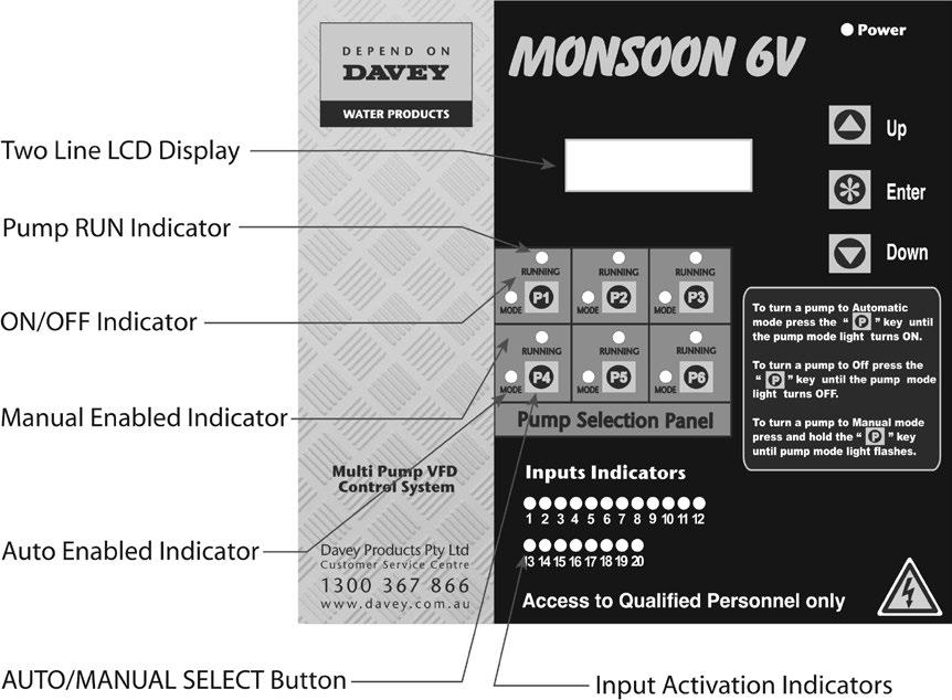
7 ~ 7 ~

8 Moving Around & Editing the Menu Items To move between the main menu screens press the UP or DOWN key. To enter an adjustable sub menu press the ENTER key. Access to these menus is controlled by an access code, which needs to be entered prior to accessing the editable section of the menus. If the access code is not inserted correctly the system will disable entry into the submenus and the use of any pump select or enable keys. To edit a value press the ENTER key and the UP or DOWN key simultaneously until the desired value is displayed. To move out of a submenu scroll to the top or bottom of the submenu and the display will return to the main menu area. ~ 8 ~
9 ~ 9 ~

10 The MONSOON 6V controller has a multitude of adjustment menus to allow the system to be tuned to suit each application. These are listed below and explained throughout this manual. Menus throughout this manual show the complete range of options available. If a menu is not needed because the option is disabled then these screens will not appear. For example if only 3 pumps are implemented then screens with options for pumps 4 to 6 will be hidden. ~ 10 ~
11 ~ 11 ~
12 ~ 12 ~
13 ~ 13 ~
14 ~ 14 ~
15 ~ 15 ~

16 SYSTEM DISPLAY MENUS Set-Pr Actual -Pr number display Flow-Rate Vfd-Sp number display Set Point and System Pressure The system pressure is a direct measurement of the pressure in the discharge pipeline of the system. It is read from the pressure XXXX XXXX transducer and is displayed on the pressure screen on the front of the switchboard along side the set point pressure. If the jockey pump is running on the main VFD, then the jockey pump set point will appear. This will be denoted by JP alongside the value. The maximum operating pressure with the default pressure transducer is 1750kPa (250psi). Pressures greater than 80% of this figure require the use of an external pressure transducer rated to the operating pressure required. This is the default display screen, it will display appropriate messages describing current conditions. These include in order of priority: Emergency Stop, Hi Press Shutdown, Lo Press Shutdown, No Flow Shutdown, Vfd Shutdown, DOL Backup Mode, New Fault, Lo Flow Detected, Pipe Fill Mode, Pause On JP Run, Pause Activated and High Press Limit. After 25 minutes from the last key press the MONSOON 6V will revert to this screen automatically. Flow Rate and Vfd Speed Set-Pr Flow-rate Actual-Pr VFD-Sp The MONSOON 6V can operate on a calculated flow rate or via a XXXX XXXX 4-20mA input from a flow meter. The flowrate is displayed in this screen and will show * adjacent to the flowrate number if the flowrate is a calculated flow. If the flow input is determined from a flow meter the flow is nominated without the asterisk. The calculated flow rate uses information that is input into the pump flowrate screen to provide an estimation of the flow rate at any time. This calculation automatically compensates for the number of pumps operating and the speed of the VFD pump - it is useful in determining the system capacity. The actual flow for the VFD pump is calculated based on the pump speed and then affinity laws calculate the expected VFD pump Flowrate. This is a calculated flow and must be treated as such. The time base for this flow is in flow per MINUTE and is not adjustable. The VFD Speed is displayed as a percentage of maximum speed and is for informational purposes only. When a system fault is registered a NEW FAULT message will appear on the main screen. It will also be logged in the FAULT HISTORY menu. There is space for up to 5 faults to be logged which scroll down as new faults are received. ~ 16 ~

17 In the event of a new fault, which has been automatically reset, the default screen will display the message New Fault. Go to the FAULT HISTORY to view this fault. Faults that are active will remain live on the screen until the ENTER Key is pressed to clear the fault. Faults will appear in the sub menu in the following format with the time and date included on the screen. Nb. The FAULT HISTORY menu is cleared when the system is first powered up. * * NEW FAULT * * F1 Hi Shut 16/08/05 20:00 If there is a problem with the clock or the clock hasn t been initialised correctly then error will appear along with the fault. See Set Time and Date in the CONFIGURE menu for more details. Pump 1-6 Shutdown signifies that the corresponding Pump protect 1-6 input has been activated for the period of the input delay time. A High Temperature fault is recorded when the temperature rises above 60 degrees C. This fault will continue to be updated if the temperature continues to rise along with the time and date that the highest temperature was recorded. This fault stops being updated when the temperature drops below 55 degrees C. After this a new fault will appear if the temperature rises above 60 degrees C. F1 Hi Temp 69C 01/04/05 11:51 Auto Reboot denotes that the MONSOON 6V has automatically restarted due to an internal glitch, whereas Power Failure records that the MONSOON 6V has recovered from a power supply problem. The FAULT HISTORY menu is always visible regardless of whether the access code is correct. ~ 17 ~
18 Flow Total The total flow is displayed in this screen. This flow total is calculated from the flow rate input and can be read either from a flow meter or calculated for the Flow Rate figure set in the pump flow rate screen in SETTINGS. Flow Total XXXXXXX L If the MONSOON 6V uses the flow rate/min to calculate the totalled flow for the system. This figure is based on the average flow input into the system. The accuracy is dependent on the average flow information but should be in the order of ±5%. Variation of site conditions such as suction pressure can affect the accuracy of this figure. The FLOW TOTAL is updated every 1 minute. As the FLOW TOTAL is calculated it is important to note that this is not an actual totalled flow and the accuracy is dependent upon the input average flow accuracy. This figure can be reset by pressing ENTER then DOWN and then ENTER again. Average Flow Rate The average flow is registered since the last reset of this calculation. The flow units are based on the tuning of the system and uses either calculated flow or input from a flow meter. To reset press ENTER then DOWN and then ENTER again. Average Flow Rate XXXX L/min Average Pressure The average pressure is registered since the last reset of this calculation. To reset press ENTER then DOWN and then ENTER again. Average Pressure XXXX kpa Hours Run Pump 1-6 Each pump has an hour run meter attached to record the actual run time for each pump. The hour log will accumulate all of the operation time for each pump in both AUTOMATIC and MANUAL modes. To reset the time press ENTER then DOWN and then ENTER again. Hours Run Pump1 XXXXX Pump 1-6 Starts The MONSOON 6V registers the number of starts that each pump accumulates to assist in the tuning of the system. This number can assist in the selection of the cut in and cut out pressures and the run time settings. The starts do not increment when selected in MANUAL as this is considered an override function. To reset press ENTER then DOWN and then ENTER again. Starts Last Hour This registers the numbers of starts that the TOTAL SYSTEM had over the past hour. This is the accumulation of all of the starts for all of the pumps and is designed to assist in trouble shooting. The new number is accumulated over a 10-min period and is updated at 10-minute intervals. To get a true hourly reading the system must have been running for at least 1 hour. After the first hour the last 6 previous 10-minute readings are added together to get the Starts last hour reading. To reset press ENTER then DOWN and then ENTER again. Analogue Input 1 Pump Starts 1 XXXXX Starts Last Hour XXXXX This screen displays the actual analogue input reading in percentage. e.g. If the analogue input was 12mA on a 4-20mA selection then the reading in this screen would be % - Analogue Input 1 XXX.XX% 12-4 =8.8/(20-4)16=50% ~ 18 ~
19 Analogue Input 2 As per analogue input 1. See INPUTS for configuration options Analogue Output 1 This screen displays the actual analogue output reading in percentage. This item is reserved for VFD speed and cannot be varied. Analogue Output 2 This screen displays the actual analogue output reading in percentage. See OUTPUTS for configurable options for this item. Digital Input State M (Main Inputs) This screen displays the state of the digital inputs X = energized - = de-energized See INPUTS for configurable options for this item. Digital Input State E (Expansion Board Inputs) State of the digital inputs on expansion board X = energized - = de-energized See INPUTS for configurable options for this item. Screen only visible if expansion board is present. Analogue Input 2 XXX.XX% Analogue Output 1 XXX.XX% Analogue Output 2 XXX.XX% Digital Input M X- -X X- -X Digital Input E XX - X X Digital Output State This screen displays the state of the digital outputs X = energized - = de-energized See OUTPUTS for configurable options for this item. Digital Output X - - X PID Error This screen displays the error from the calculated set point compared with the actual pressure. Temperature Displayed is the current temperature in degrees C, read via the temperature sensor. PID Error XXX.XX% Temperature XXX degrees C Access Code XXX Press ENTER to edit the access code at this location. If correct this will then allow access to the Sub Menus. Once the access code is input it will remain active for 25 minutes after the last key press. Standard security will then resume and access into the submenus will equire re-entering the Access Code. The system will then automatically lock the use of the keys which control the ON/OFF and AUTOMATIC and MANUAL functions. This is designed to protect the system from tampering. * KEYPAD LOCKED * Enter Access Code If a message KEYPAD LOCKED appears on the screen enter the ACCESS CODE to allow access. ~ 19 ~
20 Low Pressure Shutdown Alarm pressure point for low pressure. If any pump is running and the system falls below this pressure and remains there for the period of the LoPressure Delay time, the system will then shut down. An alarm message will show on the main screen showing that there is a low pressure shutdown fault. The fault will also be recorded in the FAULT HISTORY sub menu. To clear the fault and restart the system press the ENTER key. LoPress Shutdown XXXX kpa LO PRESS SHUTDOWN Nb. All pumps will be shutdown including manual pumps. Cut In Pressure The cut in pressure is the pressure at which the system will restart. This pressure must be higher than the low pressure shutdown and lower than the lowest set point pressure. Cut In Pressure XXXX kpa Set Point The set point is the pressure that the system will attempt to maintain when called to operate. This set point is unit-less and is determined by the operator and the setting of the pressure transducer. This setting is limited to a value that is lower than the high pressure limit. Set Point XXXX kpa ~ 20 ~
21 High Pressure Limit The high pressure limit is a pressure setting that trips the system if the pressure rises above this setting. Once the system pressure rises above this figure then the fixed speed pumps will shut down at 0.3- HiPress Limit XXXX kpa second intervals and the VFD rapid decelerates at 100%/sec. If the system pressure returns to below this setting then the MONSOON 6V will attempt to regain the set point and function normally. This setting is limited to a value that is lower than the high pressure shutdown and higher than the highest set point. (This includes all other Set Points 2 to 8) When a DOL pump is turned off, the following message will be displayed on the main screen for 5 seconds. HIGH PRESS LIMIT If pressure is above High Pressure Limit turning on manual pumps is disabled. High Pressure Shutdown The high pressure shutdown is a pressure setting that shuts down the system if any pump is running and the pressure rises above this setting for longer than the High Pressure Delay time. This feature has the capacity to be set for auto reset after tripping in the fault re-start screen or to be turned off. This setting is limited to a value that is higher than the high pressure limit. Nb. All pumps will be shutdown including manual pumps. Pump Flow Rate HiPress Shutdown XXXX kpa There are two options for the flow rate figure: Actual flow rate Calculated flow rate Pump Flow Rate XXXX L/min ACTUAL FLOW RATE The analogue input programmed for flow rate input will read the input from a flow meter to register the flow. This input is a 4-20mA analogue signal only. See flow meter calibration (CONFIGURE) for additional information. CALCULATED FLOW RATE This figure is the flow rate of the pump at the nominated set point at full motor speed. It is read from a manufacturers pump curve and input as a flowrate / minute. Any units can be used for this figure however the time units are fixed at MINUTES. Each time the set point is changed this figure must be modified to maintain an accurate figure. The calculation is done on the number of pumps running at any time with an adjustment for pump speed on the VFD pump based on Affinity Law calculations. Friction Loss Friction Loss Friction loss is the figure that is added to the set point to compensate for friction in a pipeline. The result of this setting is to increase the set point XXXX kpa pressure based on the flow rate calculated. The increase in set point is linearly proportional to the calculated flow rate. The input figure is the total additional pressure required when all of the nominated pumps are operating. ~ 21 ~

22 Nb. It is good practice to keep the friction loss figure less than the difference between your highest set point and high pressure limit. Set Point 2-8 MONSOON 6V has eight possible set points that can be triggered by a digital input. This allows a variation to the actual set point to be made remotely. It changes the reference set point to the value nominated. This occurs when an input is programmed to function as set point 2 to 8 and is activated by closing the contact between the nominated input and the input common. Screens set point 3 8 are only visible if an available input is nominated as the corresponding set point within the INPUTS menu. Pressure Trip 1 Low MONSOON 6V has the ability to energize an output relay based on specific system pressure points. This can be useful for monitoring other functions through out the system that are not directly affected by the MONSOON 6V control. See output relays for information on how to set this feature. Set Point 2 XXXX kpa Press Trip 1 Low XXXX kpa If an output relay is set to operate on pressure trip 1 then the relay will energize based on the settings input into pressure trip 1 low and pressure trip 1 high. Pressure Trip 1 High The high trip point is that mating pair to the low trip point. If a single trip point is required set the high and low trip points to the same value. Note: The settings of trip high must be greater or equal to trip low. The system constrains settings outside this range. Press Trip 1 Hi XXXX kpa The Pressure Trip 1 Low and Pressure Trip 1 High screens will only appear if an output is set to pressure trip 1 within the OUTPUTS menu. ~ 22 ~
23 Pressure Trip 2 Low Operates as per Pressure Trip 1 Low. Press Trip 2 Low XXXX kpa Pressure Trip 2 High Operates as per Pressure Trip 1 High. The Pressure Trip 2 Low and Pressure Trip 2 High screens will only appear if an output is set to pressure trip 2 within the OUTPUTS menu. Flow Trip Low This setting is used to energize an output relay if the flow rate is below this figure. The delay time for this setting is defined in the TIMING menu under flow trip low delay time. See OUTPUTS for additional information. Flow Trip High This setting is used to deactivate an output relay if the flow rate is above this figure. The delay time for this setting is defined in the TIMING menu under Flow Trip High Delay Time. See OUTPUTS for additional information. The Flow Trip Low and Flow Trip High screens will only appear if an output is set to flow trip within the OUTPUTS menu. DOL Cut In Press Trip 2 Hi XXXX kpa Flow Trip Low XXXX L/min Flow Trip Hi XXXX L/min In the event of a VFD failure the MONSOON 6V has the option to select a DOL backup mode which allows the system to function as a switched pressure system. DOL Cut In XXXX kpa In event that the DOL backup mode is selected to On the system will operate between the DOL cut in and DOL cut put pressures. Refer to DOL Backup Mode in CONFIGURE for a fuller description. DOL cut in must always be higher than low pressure shutdown and will be equal to or less than DOL cut out. In this mode all delay times still operate as per the standard system. ~ 23 ~

24 DOL Cut Out The screens DOL Cut In and DOL Cut Out will only appear if DOL backup mode is enabled within the CONFIGURE menu. DOL Cut Out XXXX kpa DOL Cut Out must always be lower than high pressure limit and will be greater than or equal to DOL Cut In. TUNING Minimum Frequency The minimum frequency is the lowest setting at which a pump will begin to contribute to the system pressure. This value is expressed as a percentage. This is the frequency at which the MONSOON 6V determines that a pump is to be disengaged when the system flow demand is dropping. Min Frequency XXX.X% To determine your pumps minimum frequency (as a percentage), get the min frequency (Hertz), from your pumps data sheets and divide it by the maximum speed of the pump (Hertz). Then multiply the resulting number by 100 to get minimum frequency (%). Response Rate The response rate is a figure used to set the speed of reaction of the system. Response Rate XXX.X% It is expressed as a percentage ranging from is the slowest response and the fastest. Acceleration The acceleration of the VFD can be limited by this figure. It is designed to brake the PID control. It is used in cases where the acceleration needs to be dampened. The figure is input in %/second. Acceleration XXX %/second Auto-Rotation This menu allows MONSOON 6V to call on one pump to be the lead pump or to allow for a new pump to be the lead pump after each time all of the pumps have shutdown. Auto Rotation FULL Nb. The lead pump is the name given to the first auto pump to start (if available). The options are Full,1,2,3,4,5,6, Every 24 Hours and Low Hours. If a number is selected then that pump will always be the lead pump. If Full is selected then the lead pump will cycle after system shutdowns or PAUSE events. If set to Every 24 Hours, once every 24 hours the system will shutdown all auto pumps (including jockey) and force a cycle of the lead pump. ~ 24 ~
25 Selecting Low Hours will start the next available pump with the lowest hours according to the individual hours run meters as seen in PUMP DATA LOG. The aim of the setting is to get an even wear through all of your pumps. A forced rotation can be activated by setting one of the programmable inputs to Cycle Pumps and closing the relevant input terminals- see programmable inputs. If the jockey pump function is enabled pump 1 will become the jockey pump and will not auto-rotate. See JOCKEY PUMP and PUMP DEFINITION for more information. High Pressure Restarts This setting allows the operator to set the number of times that the system can shutdown and then automatically restart after a high pressure shutdown. The range is from Off, Select Off to HiPress Restarts XXX make the system shut down immediately after the High Pressure delay timer trips. This is the safest setting and the default for the system. After each automatic restart the fault is logged in FAULT HISTORY and the message New Fault appears on the main screen. Standby Boost / Standby Flow Min The MONSOON 6V uses one of three methods to determine if there is no flow in the reticulation. The options detailed below are selected via the Standby Test screen, which is in the CONFIGURE menu. Each test Standby Boost XXX kpa is only carried out if there is only 1 pump running, it s not at maximum speed and the system pressure is at or above 3% of the set point. Boost: The MONSOON 6V tests to see if the system flow has stopped by boosting the system pressure. The Standby Boost pressure sets the amount the set point pressure is boosted by. The time that it takes to drop back to the set point is compared to the sandby test time. If the time to return to set point is less than the Standby Test time then the system continues to operate. In this mode the Standby Boost screen will be visible and Standby Flow/min will be hidden. Flow Switch: If a flow switch closes the contact between the no flow input then the system assumes that there is no flow and shuts down after the period nominated by the standby test time. In this mode both the Standby Boost and Standby Flow/Min screens will be hidden. Flow Rate: If the flow rate in the system is below the nominated amount in this menu for the period of the standby test time the system will shut down. Standby Flow Min XXX L/min In this mode the Standby Flow Min screen will be visible and Standby Boost will be hidden. ~ 25 ~
26 Integral Time The integral time is the time it will take to convert a constant error of 1% to a 1% change on the output. The integral component is proportional to the tracking error and increases linearly with time. It Integral Time XXX.X seconds is useful when trying to close the gap on small errors that can not be eliminated through the use of the response rate alone. It is expressed as a percentage ranging from Off, Off will disable this part of the PID equation. Derivative Gain The derivative gain is used to provide a damping effect to eliminate system oscillation and to minimize overshoot. Derivative Gain XX.XX % It is expressed as a percentage ranging from Off, Off will disable this part of the PID equation. Proportional Output This screen displays the proportional component within the PID equation. Proportional is another name for the response rate. Integral Output This screen displays the integral component within the PID equation. Derivative Output This screen displays the derivative component within the PID equation. Prop Output XXXX Integral Output XXXX Deriv Output XXXX These three Output display screens can be used to help tuning of the MONSOON 6V. Each has a range of to See PID Control for more information. TIMING Low Pressure Shutdown Delay Set this time to delay the low pressure shutdown. It must time out before the system will shut down in low pressure mode. The range for this is OFF, sec. If OFF is selected then the system will ignore any low-pressure shutdown commands. Be sure that you fully understand the repercussions of this setting as the shutdown settings are designed to protect both the pump and the system from damage. The low & high pressure delay timers are independent of each other and can be set to suit individual needs. High Pressure Shutdown Delay Set this time to delay the high pressure shutdown. It must time out before the system will shut down in high pressure mode. The range for this is OFF, sec. If OFF is selected then the system will ignore any high-pressure shutdown commands. Be sure that you fully understand the repercussions of this setting as the shutdown settings are designed to protect both the pump and the system from damage. In Delay Timer The IN DELAY TIMER is used to delay the starting of additional pumps. When the system pressure drops below the cut in pressure the system instantly starts the first pump according to the restart timer. Any additional pumps required will not start until the maximum pump speed is reached, the system is below set point and in delay timer has elapsed. This timer is designed to assist in the reduction of short cycling and allowing the system to stabilize before additional pumps are started. ~ 26 ~ LoPressure Delay XXX seconds HiPressure Delay XXX seconds In Delay Timer XXX seconds

27 TIMING Out Delay Timer When the pumps are called to shut down the delay for this is governed by the OUT DELAY TIMER. It delays the shutting down of additional Out Delay Timer pumps when the system pressure is above the set point and pumps XXX seconds are attempting to shut down. Take care in setting this timer as the increase in pressure due to this delay can cause pressure spikes. Restart Delay When the system pressure drops below the cut in pressure the first auto pump to start will be delayed by the RESTART DELAY. Standby Test Time The MONSOON 6V uses one of three methods to test if there is no flow in the system. These are determined by the standby test screen in the CONFIGURE menu. Each test is only carried out if only 1 pump is running and not at full speed. Restart Delay XXX seconds Standby Test Tm XXX seconds - Boost After a positive outcome from a pressure fall test the system will boost the pressure by the Standby Boost setting and track how long it takes for the actual pressure to drop to the set point pressure. The standby test timer selects how long this time should be. If the set point pressure is reached in a time less than this timer then the system will continue to operate. If the Set Point is not reached in the time prescribed then the system will shut down. - Flow Switch If a flow switch closes the contact between the no flow input then the system assumes that there is no flow and shuts down after the period nominated by the standby test time. - Flow Rate If the flow rate in the system is below the nominated amount in this menu for the period of the standby test time the system will shut down. See TUNING menu for more details on Standby test. ~ 27 ~
28 Boost Hold Time When the system does a standby test boost, instead of dropping the set point back down once the new pressure has been reached this timer will hold the set point at the boosted value for the time nominated. Boost Hold Time XXX seconds This screen is only visible if Boost is selected in the standby test screen within the CONFIGURE menu. No Flow Timer If the system decides there should be flow and the flow switch is closed this timer delays a no flow shutdown by the given amount. Input Delay Timer The MONSOON 6V has the capacity to accept input signals for various processes. This timer sets the delay for reaction to those inputs. The specific inputs that are controlled by this timer are:- NO FLOW and PUMP 1-6 PROTECTION. No Flow Timer XXX seconds I/P Delay Timer XXX seconds Pressure Trip Low Delay This setting delays the activation of the relevant output relay if programmed for pressure trip. This delay timer is relevant for both Pressure Trip 1 & 2 settings. Pres Trip Lo Dly XXX seconds Pressure Trip High Delay This setting delays the deactivation of the relevant output relay if programmed for pressure trip. This delay timer is relevant for both Pressure Trip 1 & 2 settings. Pres Trip Hi Dly XXX seconds The screens Pressure Trip Low Delay and Pressure Trip High Delay are only visible if at least one output is set to Pressure Trip 1 or Pressure Trip 2 in the OUTPUTS menu. Flow Trip Low Delay This setting delays the activation of the relevant output relay if programmed for flow trip. This delay timer is relevant for the low flow trip setting. Flow Trip Lo Dly XXX seconds Flow Trip High Delay This setting delays the deactivation of the relevant output relay if programmed for flow trip. This delay timer is relevant for the high flow trip setting. Flow Trip Hi Dly XXX seconds The screens Flow Trip Low Delay and Flow Trip High Delay are only visible if an output is set as Flow Trip in the OUTPUTS menu. Change Over Delay Motors needs to operate with a deflux delay time. The change up and change down routine can be changed so that the delay time between the contactors of the same motors will delay for a nominated period of time. This allows the motors magnetic field to decay before bringing in the VFD or mains bypass contactor. Change Over Delay XX.XX seconds ~ 28 ~
29 Operating Mode Select the control parameter relevant to the operation. The options are: Pressure Control Level Control Flowrate Control Temperature Control Operating Mode Pressure When the relevant selection is made the menu screens will change to reflect the control parameters. Number of Pumps Select the number of pumps in the system. The menus will change to suit the selection. Number of pumps X ~ 29 ~
30 Transducer Zero The transducer zero adjusts the zero offset in the pressure sensor. Remove all pressure in the system and then trim the display by pressing ENTER and then the UP or DOWN keys to set the reading to 0. There Transducer Zero XXXXX kpa are buffers in the system so the transition to the new reading may take some time to settle, wait at least 5 seconds before accepting the adjustment. If MONSOON 6V senses that the adjusted zero input is lower than can be accepted, a message will come up on the screen stating VALUE TOO LOW. If this message appears, increase the setting slowly by pressing ENTER and then UP, press ENTER again to confirm. Exit out of the menu to store the value. Adjust Pressure The calibration of the analogue sensors is achieved by adjusting the pressure reading on this screen to match a reading from a pressure gauge. Adjust Pressure XXXXX kpa Once the system pressure has stabilized, press the ENTER key and then either UP or DOWN keys to match the reading on this screen to suit a pressure gauge reading. Once the readings are matched the system pressure is calibrated. Press ENTER again and then exit out of the menu to store the data. There are buffers in the system so the transition to the new reading may take some time to settle, wait for 5 seconds before accepting the adjustment. Averaging To allow the system pressure to be displayed without significant pressure bouncing the MONSOON 6V averages the readings taken. To damp the pressure reading insert a high number. Averaging XX Flow Meter Zero The flow meter zero adjusts the zero offset in the flow meter input. With no flow rate in the system trim the display by pressing ENTER and then the UP or DOWN keys to set the reading to 0. Be sure Flow Meter Zero XXXXX L/min that the flow meter is connected to the relevant input. If the value input is too low then the message VALUE TOO LOW will appear on this screen. If this has occurred press the UP key until a zero value appears. Press ENTER again and then exit out of the menu to initiate a store of the zero value. Adjust Flow The calibration of the analogue sensors is achieved by adjusting the Flow Meter reading on this screen to match a reading from the Flow Meter output screen. Adjust Flow XXXXX L/min ~ 30 ~
31 Standby Test The MONSOON 6V uses one of three methods to determine if there is no flow in the reticulation: Standby Test Boost Boost- Add extra pressure to the system and time how long it takes to get back to the set point. Flow switch- If a flow switch closes the contact between the no flow input then the system assumes that there is no flow and shuts down. Flow Rate- If the flow rate in the system is below the nominated amount in this menu the system will shut down. For more information see Standby Boost section in the TUNING section. Set Time / Date Set the relevant field by pressing the ENTER key. To change fields press the ENTER KEY again. This will highlight the next set of numbers. A flashing cursor will signal which field is being edited. Set Time/Date 00: Jan 01 If the screen reads 00: Jan 01 (the default), then the time and date need to be initialised. Set the relevant fields as above. ~ 31 ~
32 Operating System Select the type of operation that is required for the system. Options: Cascading Lead VFD Lag All VFD Operating System Cascading CASCADING The MONSOON 6V starts the first pump via the VFD and continues to accelerate until the pump reached full speed. If the system is not at the set point the controller then cycles the VFD to the next pump and switches the initial pump to full speed. This operation continues until the set point is reached or all pumps are running. The reverse occurs as the demand reduces. One VFD and bypass contactors are supplied for this option. LEAD VFD LAG The MONSOON 6V starts the first pump via the VFD and continues to accelerate until the pump reached full speed. If the system is not at the set point the controller starts a LAG pump to make up for the flow demand. This is typically via a soft starter. This operation continues until the set point is reached or all pumps are running. The reverse occurs as the demand reduces. One VFD and backup soft starters are supplied for this option. ALL VFD The MONSOON 6V starts the first pump via the VFD and continues to accelerate until the pump reaches full speed. If the system is not at the set point the controller then cycles the VFD to the next pump and switches the initial pump to full speed. This operation continues until the set point is reached or all pumps are running. The reverse occurs as the demand reduces. One VFD per pump is supplied for this option. DOL Backup Mode In the event of a VFD failure the MONSOON 6V has the option to select a DOL Backup Mode which allows the system to function as a switched pressure system. To enable DOL Backup Mode set this screen as ON, before a VFD failure has occurred. DOL Backup Mode OFF If the system was to experience a VFD failure then the system will run between the CUT IN and CUT OUT pressure whilst in VFD Fail mode. To reset this mode power the system down and restart. Low Pressure Shutdown, High Pressure Limit and High Pressure Shutdown are active within this mode. ~ 32 ~


33 Friction Loss Calculation There are two methods of calculating the pressure loss. 1. Linear progression. 2. Exponential extrapolation. Friction Loss Linear Friction loss is the figure that is added to the set point to compensate for friction in a pipeline. The result of this setting is to increase the set point pressure based on the flow rate calculated. The increase in set point is linearly proportional to the calculated flow rate. The input figure is the total additional pressure required when all of the nominated pumps are operating. User Access Code The access code is used to limit access to the settings menus. The user Access Code access code has the range off, Off will disable the access code and allow unlimited access. Once a number is selected then access XXX to the settings screens or any other editable screen will require the inputting of this number to progress. to edit press enter and then up or down keys to edit the new number. Press enter again and exit the menu to store the changes. Pump 1-6 Each pump can be defined as: Duty Standby Duty- If the pump is defined as duty the relevant pump will be available for operation at all times if required. Standby- If a pump is defined as a standby pump it will remain dormant unless one of the duty pumps faults (via pump protect input), It will then automatically become a duty pump until redefined in this screen. Pump 1 can also be defined as jockey. See the JOCKEY section for more information. The number of pumps visible in these screens is determined by the number of pumps screen within the CONFIGURE menu. ~ 33 ~ Pump 1 Duty
34 The jockey pump is typically a smaller auxiliary pump that is outside the flow range of the main pumps. The jockey pump will turn on when there are no main pumps on and the pressure is below Jockey Cut In Pressure. If pump 1 is not defined as jockey then the following screen will be displayed when you try to enter the JOCKEY sub menu. JP Cut In Pressure No Pumps Set As Jockey Pump The JP Cut In Pressure is the pressure below which the pump defined as jockey pump will restart. This value will be constrained by JP SET POINT. JP Cut In Press XXXX kpa JP Set Point / Cut Out The set point is the pressure that the jockey pump will attempt to maintain when called to operate. This value will be constrained by HIGH PRESSURE LIMIT. JP Set Point XXXX kpa This screen will appear as JP Cut Out Press when jockey pump mode is set as DOL. JP Response Rate The response rate is a figure used to set the speed of reaction of the system. This value is specific to when the jockey pump is running on the VFD. JP Response Rate XXX.X % It is expressed as a percentage ranging from is the slowest response and the fastest. JP Acceleration The acceleration of the VFD can be limited by this figure. It is designed to brake the PID control. It is used in cases where the acceleration needs to be dampened. The figure is input in %/second. JP Acceleration XXX %/second JP Standby Boost The MONSOON 6V tests to see if the system flow has stopped by boosting the system pressure. The Standby Boost pressure sets the actual pressure it is boosted by. The time that it takes to drop back to the set point is compared to the Standby Test timer. If the time to return to the set point is greater than this time, then the system shuts down. If the time to return to set point is less than the Standby Test time then the system continues to operate. ~ 34 ~ JP Standby Boost XXX kpa
35 JP Run On Time The jockey pump can be forced to run on after the main system has started by the time detailed in this screen. JP Run On Time XXX seconds Nb. The jockey pump will not run on when selected as MAIN VFD in the JOCKEY PUMP MODE menu. Instead it will instantly turn off when an auto pump starts. JP Restart Delay When the pressure drops below the JP Cut In Pressure and remains there the jockey pump will start after this period. Given no auto pumps have started. JP Restart Delay XXX seconds JP Min Frequency This is the minimum frequency specific to the jockey pump. See MINIMUM FREQUENCY in TUNING menu for more information. JP Min Frequency XXX.X % JP Integral Time The integral time is the time it will take to convert a constant error of 1% to a 1% change on the output. This is useful when trying to close the gap on small errors that can not be eliminated through the use of the response rate alone. This value is specific to when the jockey pump is running on the VFD. It is expressed as a percentage ranging from OFF, OFF will disable this part of the PID equation. JP Derivative Gain JP Integral Time XXX.X seconds The derivative gain is used to provide a damping effect to eliminate system oscillation and to minimize overshoot. This value is specific to when the jockey pump is running on the VFD. JP Deriv Gain XX.XX % It is expressed as a percentage ranging from OFF, OFF will disable this part of the PID equation. Jockey Pump Mode The jockey pump can function on any of the settings below: Jockey Pump Mode Main VFD Main VFD- The jockey pump will be run on the main VFD. It will try to maintain set point via the response rate, integral time and derivative gain. In this mode the jockey pump will turn off whenever any auto pumps start. Seperate VFD- The jockey pump will run on its own dedicated VFD. It will try to maintain set point via the response rate, integral time and derivative gain. In this mode when an auto pump starts the jockey pump will continue to run in DOL mode until the run on timer expires. DOL- The jockey pump will be run from a DOL contactor. It will run as a switched pressure system with JP Cut In and Cut Out. In this mode when an auto pump starts the jockey pump will continue to run while the run on timer is active. ~ 35 ~
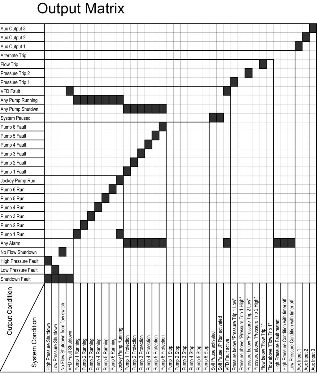
36 MONSOON 6V has four main programmable outputs that can be used to communicate with external sources such as Telemetry or Building Management Systems (BMS). As each system requires different combinations of information all output relays are configurable in software. All outputs are Voltage Free - Change Over contact outputs and capable of 5 amps 240 VAC. If the expansion board is fitted four more programmable outputs are available. You can view which outputs are currently activated within the PUMP DATA LOG menu, under digital output state. The status of the analogue outputs is also available within this menu. ~ 36 ~

37 Shutdown Fault This output is used to indicate that there has been an event that has shut down the system. This can be either a High or Low-Pressure Shutdown, No Flow Shutdown or VFD Shutdown. Low Pressure Fault A shutdown based on a Low Pressure Shutdown. High Pressure Fault A shutdown based on a High Pressure Shutdown. Any Alarm If there are any fault re-starts active this output will activate or any situation that would have caused a shutdown if the delay timers were active. Pump 1-6 Run Pump 1-6 running. Pump 1-6 Shutdown Pump 1-6 shutdown on individual pump protection. System Paused Either System Pause or System Pause JP Run inputs have been activated. ~ 37 ~
38 Any Pump Shutdown Any pump shutdown will activate the relay. Any Pump Running Any pump running will activate the relay. No Flow Shutdown The No Flow Shutdown action is active. VFD Fault Output is on when the VFD is being tested or the VFD has shutdown. Pressure Trip 1 When the system pressure reaches the nominated Pressure Trip 1 Low and High, this relay will energize or de-energize. See pressure trip in SETTINGS. Pressure Trip 2 When the system pressure reaches the nominated Pressure Trip 2 Low and High, this relay will energize or de-energize. See pressure trip in SETTINGS. Alternate Trip Each time the system shuts down the energized state of the relay will change. E.g. If the relay on one cycle is closed during operation then the next cycle this relay will be open. The relay will change on the following: - Low Pressure Shutdown, High Pressure Shutdown, No Flow Shutdown and VFD Shutdown. Flow Trip When the system flow reaches the nominated Flow Trip points Low or High, this relay will energize or de-energize. See flow trip in SETTINGS. Aux Outputs 1-3 Any output can be set to be an auxiliary output. Setting an output to become an auxiliary output allows the MONSOON 6V to use an input to turn on a digital output. To do this the input has to be set up to be an auxiliary input. There are three auxiliary functions available. Aux Input 1 operates Aux Output 1 Aux Input 2 operates Aux Output 2 Aux Input 3 operates Aux Output 3 * RELAY RATINGS The relays are rated at 5 amp 250VAC. Consideration of inrush current, inductive loads and cycling must be taken into account when applying current to these relays. ~ 38 ~
39 ~ 39 ~
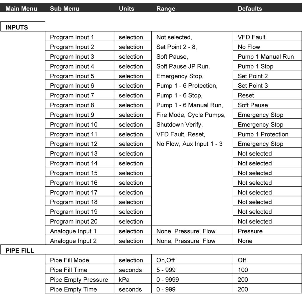
40 There are 12 main inputs with the MONSOON 6V that control the external sensing functions. If an expansion board is fitted there are 8 more inputs available. All inputs are programmable to suit various applications. They all require VOLTAGE FREE contacts and as such should NOT HAVE ANY VOLTAGE APPLIED. All inputs operate on a CLOSED CONTACT for registration. This contact needs to be made between the input common and the relevant input. There are three terminals for the input common to allow for multiple connections. You can view which inputs are activated by the leds on the front of the unit and also within the PUMP DATA LOG menu under the Digital Input State screens. See PUMP DATA LOG for more information. ~ 40 ~

41 Not Selected When this is selected the input will not respond to activation. ~ 41 ~
42 Set Point 2-8 Closing of the contact to either of these inputs will activate the alternate set points 2 to 8. If two inputs are activated at the same time, then the set point with the highest number will be the selected option. Eg If Set Points 2 and 6 are activated set point 6 pressure setting will be used. The Set-Pr will also change on the main display. Soft Pause An external sensor can be used to PAUSE the system. When the system receives a PAUSE command the system will shut down in a PAUSE ACTIVATED controlled manner based on the rates set in the response rates menu. The system will slowly drop the pressure causing all pumps running to turn off one at a time and a message will be shown on the main screen. After the PAUSE input has been deactivated the system will restart under normal operations. If the autorotation is selected to FULL the lead pump will rotate. Soft Pause JP Run This is the same as soft pause except the jockey pump will continue to operate if fitted. PAUSE ON. JP RUN Indicated a message: - Emergency Stop An external sensor can be used to STOP the system. This is particularly useful for sites with suction tanks to halt the pumping operation until the tank is allowed to reach a suitable level for pumping. There are numerous other applications for the system pause function. * EMERGENCY STOP * When the system receives a STOP command the system will immediately shut down all pumps and indicate a message. After the STOP input has been deactivated the system will restart under normal operations and return pumps to the modes they were before the stop. Pumps in MANUAL mode will automatically restart after deactivation of the input. If the auto-rotation is selected to FULL the lead pump will rotate. Pump 1-6 Protection MONSOON 6V has inputs for each pump to allow for individual pump protection. In the event of a pump going into a fault condition the input for that pump should close. This will shut down the pump after the time set by the input delay timer. The pump will become available again when the input contact is opened. This protection is ideal for the following pump protection sensors: Temperature probes Loss of prime pressure switches Thermal overloads Moisture sensor for oil bath pump seals Any individual pump protection device. Pump 1-6 Stop Activation of this input will instantly stop the operation of the relevant pump. This can be used as an off override switch in the system or if the remote control of a pump is required. This input will override the relevant Pump 1-6 Manual Run input when both active. Pump 1-6 Manual Run Activation of this input will instantly start the relevant pump. All automatic control of the pump is ceased at this stage. This action can cause an alarm or shutdown condition. (See Manual operation) ~ 42 ~
43 Fire Mode The FIRE MODE allows the system to ignore all shutdown features so the pump will continue under all conditions. The following protection features are disabled: High Pressure Shutdown Low Pressure Shutdown System Pause No Flow Individual Pump Protection Pump 1-6 Stop The operational consequences for activating Fire Mode are substantial so be sure to understand the repercussions of activating this input. It should only be used if the risk of the pump stopping is greater than letting it run to destruction. Some VFD s have a similar function and will override the protections within the VFD if an input is toggled. Contact your local dealer for further information regarding this feature. Hardware items such as circuit breakers, thermal overloads and any other switchgear protection is not effected by this mode. Cycle pumps Activation of this input will shutdown and then cycle the pumps to the next available pump as the lead pump. If pump 1 started first on the last start-up, the toggling of this input will switch the lead pump to pump 2 instantly on receipt of this signal. VFD Fault In the event of a VFD fault this input will initiate a retry cycle to attempt to reset the VFD. On receipt of this signal the system will attempt to clear the fault by sending a reset message to the VFD after a 15 second delay. This will be repeated until the VFD is restored to an operational level. During this cycle the Low-Pressure Shutdown protection is disabled to allow the system to recover automatically. De-powering and then re-energizing the switchboard will generally clear VFD faults. See VFD Fail for more configuration information Reset The reset input allows remote resetting of MONSOON 6V after a shutdown fault. If MONSOON 6V has shutdown due to a fault - for any reason - closing the reset contact will reset all current faults and restart the system (VFD Fault excluded). No Flow If the system detects that there should be flow but there is a no flow signal from an external flow switch, the MONSOON 6V will display the message Low Flow Detected. Once system detects a closed contact on Low Flow Detected XXXXX this input the MONSOON 6V will time out and shut down. This is optional and requires a flow switch to feedback into the no flow input and will only operate if there is at least 1 pump selected to AUTO. The system will only shut down if the system pressure is lower that the set point. MONSOON 6V assumes that if pressure is at set point then the system is in standard operation mode. Once the no flow delay timer has expired then the screen message changes to: No Flow Shutdown XXXXX The system pressure at the time of shutdown is displayed on this screen also. The system will not restart until ENTER is pressed to clear the fault. ~ 43 ~
44 Aux Inputs 1-3 Any input can be set to be an auxiliary input. Setting an input to become an auxiliary input allows the MONSOON 6V to use this input to turn on a digital output. To do this the output has to be set up to be an auxiliary output. There are three auxiliary functions available: Aux Input 1 operates Aux Output 1 Aux Input 2 operates Aux Output 2 Aux Input 3 operates Aux Output 3 External contacts must be VOLTAGE FREE - any applied voltage can cause damage to the system. WIRING INPUTS The built in transducer is fitted to the underside of the MONSOON 6V enclosure with a ¼ BSP female connection. This transducer is rated to 1700kPa (250 psi) with a maximum over pressure rating for spike pressure of 3150kPa (450psi). (The use of any other transducer apart from the standard one requires the disconnection of the ribbon cable connected to the standard transducer). External Analogue Input The use of 4 20mA and 0-10V transducers require JUMPERS to be fitted to the relevant posts when selected. This allows the system to read the correct input from the transducers ma is a standard analogue signal from a pressure transducer. To use this input note the wiring requirements on the PCB. A regulated 24VDC power supply is available on board for 2-wire configuration V transducers are set up for standard 3-wire operation. ~ 44 ~
45 In some cases when a system has been static for a period of time there is the need to start the pumps slowly to eliminate the possibility of water hammer. The pipe fill control will override the set point control in these circumstances. Pipe Fill Mode This screen will enable or disable the mode. If pipe fill mode is set to OFF then the next three screens ( Pipe Fill Time, Pipe Empty Pressure and Pipe Empty Time ), will be hidden. Pipe Fill Time Pipe Fill Mode = = = On = = = The operator nominates a maximum time to fill the reticulation that is acceptable for pipe filling. The system will increase the VFD from zero to maximum frequency based on the time nominated. The pipe fill time is the time taken to accelerate EACH pump to maximum frequency. Pipe Empty Pressure In order for this mode to be initiated the system must have been below the pipe empty pressure for at least the pipe empty time. Pipe Fill Time XXX seconds Pipe Empty Press XXXX kpa Pipe Empty Time Once the system cut in pressure is reached or all available pumps are on and running flat out the pipe fill mode will automatically cease and normal pressure control functions will operate. Pipe Empty Time XXX seconds Whilst in pipe fill mode the main screen will flash the message Pipe Fill Mode to inform the operator that there is a control override functioning. To disengage pipe fill mode select OFF in the first screen of this section. Whilst in pipe fill mode the Low Pressure Shutdown is disabled. ~ 45 ~

46 PUMP PROTECTION The MONSOON 6V has numerous safety features built into the system to protect the pumps from damage. Some of these shut down all operation and some are designed to halt operations until the system can stabilize. The user determines the selection of each of these. High Pressure Shutdown If the system pressure goes over the high pressure setting for a period of time, the MONSOON 6V will shutdown the system until manually reset. There is the option to allow a number of automatic restarts after this shutdown. There are restarts possible and are set in the High Pressure Restarts screen within the TUNING menu. Low Pressure Shutdown If the system drops under the specified low pressure setting for a period of time the MONSOON 6V will shutdown the system until manually reset. The retries are not available for this fault. Individual Pump Protection MONSOON 6V has inputs for each pump to allow for individual pump protection. In the event of a pump going into a fault condition the input for that pump should close. This will shut down the pump after the time set by the input delay timer. The pump will automatically restart when the input contact is opened. This protection is ideal for the following pump protection sensors: Temperature probes Loss of prime pressure switches Thermal overload Thermistor ALL FAULTS CAN BE REMOTELY RESET FROM THE RESET INPUT ~ 46 ~
47 Rotation The rotation of each pump is checked prior to shipment on packaged units; however, it is essential to check the rotation of each pump. To do this select MANUAL for each pump individually and check the rotation. If the rotation is not correct swap two of the phases coming into the main switch to reverse the rotation. Once the direction of rotation is correct for the MANUAL operation test the AUTO Operation. Turn all pumps OFF. Select AUTO for the first pump. Check rotation. If incorrect reverse any two wires on the output of the VFD. Recheck each pump. The pump stations are checked for rotation prior to dispatch however the VFD has a rotation independent of the phase orientation of the incoming wires. Note:- any wiring changes done within the switchboard should be done with the approval of the service agent and by qualified personnel only. In models with phase failure relays the mains phase orientation must be set to the correct orientation. If only one light (either green or red) is showing then swap any two wires on the main isolation switch. This orientates the main s power to the correct rotation. The pump must run in the same direction in MANUAL and AUTO Operation ~ 47 ~

48 CALIBRATION OF ANALOGUE SENSORS MONSOON 6V can accept most analogue signals from sensors and requires that a calibration routine be run to set both SCALING and ZERO OFFSET of these sensors. Go to the CONFIGURE menu and press the Enter key. ZERO ERROR The zero error routine should be done BEFORE using the Adjust Pressure screen. The zero error offset is trimmed out on the Transducer Zero screen. Make sure that there is no pressure in the system or in the tube leading to the transducer. On the transducer zero screen press ENTER to edit the data and then DOWN to make the reading go to 0. Wait for 5 seconds for the reading to stabilize. Take care when running this procedure to reduce to the zero value slowly as the possibility of running past is high. The pressure readings are averaged so the readings can lag behind the key presses. Always allow the system to stabilize prior to completing this procedure. If the value input is lower than zero a message stating, VALUE TOO LOW will appear on the screen. Press the UP key until a zero value appears. Once completed press ENTER again and back out of the menu to initiate a store of the zero value. ~ 48 ~

49 PRESSURE ADJUSTMENT For this routine it is necessary to have a reference pressure that can be used to compare the system pressure to the pressure that the MONSOON 6V senses. To calibrate the scaling for the analogue sensor apply a pressure to the system and allow it to stabilize. This can be done by manually starting one pump and then closing the main isolation vale and shutting down the pump. This should hold system pressure and remove any fluctuations that are prevalent when pumps are running. It is best to get the system pressure at least two times higher than the standard operating pressure as the calibration routine works best with an end of scale reading. Go to the Adjust Pressure screen. The pressure on this screen should match the pressure on a pressure gauge in the system. If it does not press ENTER and then either UP or DOWN to move the displayed pressure to match the gauge pressure. There is a buffer that takes approximately 5 seconds to stabilize so wait for this period to make sure that the reading is stable before accepting or editing the settings. Once the readings match and are steady then the scaling is calibrated. Press ENTER again and back out of the menu to initiate a store of the Adjust Pressure value. ~ 49 ~
50 Flow Meter Zero The Flow Meter Zero adjusts the zero offset in the flow meter input. With no flow rate in the system trim the display by pressing ENTER and then the UP or DOWN keys to set the reading to 0. Be sure that the flow meter is connected to the relevant input. Once calibrated press ENTER again and exit the CONFIGURE sub menu to store the value. Adjust Flow Flow Meter Zero XXXXX L/min The calibration of the analogue sensors is achieved by adjusting the Flow meter reading on this screen to match a reading from the flow meter output screen. Adjust Flow XXXXX L/min GENERAL The basis for these calibrations is that the sensor used has a linear error. If the instrument that is being used has a non-linear error then the system readings will be inaccurate. The standard transducer used with MONSOON 6V has these characteristics and also is fitted with temperature compensation to eliminate possible transducer drift with temperature. With standard transducers you will be able to read pressures to an accuracy of ± 4% under normal conditions. Please note that the standard transducer is rated to 1750kPa (250 psi) - do not use the transducer if the system pressures are likely to go above this pressure. It is recommended that in cases of pressure in excess of 80% of the maximum pressure to consider an external transducer. This is due to the potential shock loads on the transducer which can damage the unit. ~ 50 ~
51 PID Control The MONSOON 6V has an on board PID controller that calculates the required VFD speed to maintain pressure at set point. This calculation is based on the actual system pressure being read and the speed of any one pump. Adjustment of the response of the system to varied flows can be made by using the Response Rate menu item located in the TUNING menus. The scale for Response Rate is %. Additional to this control there is the ability to damp the response of the system by limiting the Acceleration (located in the TUNING menu). This will limit the acceleration rate of the system. It is a BRAKING method only. Integral Time and Derivative Gain both found in the TUNING menu can be used to further fine tune your system. The Integral Time is the time it will take to convert a constant error of 1% to a 1% change on the output. The integral component is proportional to the tracking error and increases linearly with time. This is useful when trying to close the gap on small errors that can not be eliminated through the use of the response rate alone. The scale for Integral Time is OFF, The Derivative Gain is used to provide a damping effect to eliminate system oscillation and to minimize overshoot. The scale for Derivative Gain is OFF, %. On start-up the MONSOON 6V will accelerate the pump to minimum frequency at 100% per second. From this point on the PID will control the actual speed of reaction of the controller to the system. ~ 51 ~

52 SHUTDOWN METHODS The MONSOON 6V tests for flow rate continuously and will determine if the pump system is contributing to the system flow. If only one pump is running and the system is at or about the set point pressure, the MONSOON 6V will run one of three standby tests as set in the CONFIGURE menu. See Standby Boost in TUNING for further details. Pressure Tank Requirements As with all pressure systems a pressure tank is recommended for use in systems with VFD pumps. The pressure tank is used to: Reduce the effects of Water Hammer Provide supplemental pressure in the system to reduce the cycle time of the pump starts. The size of the pressure tank is based on the number of starts required at very low flows. As the VFD Pump will take up the lower flows the only requirement for the pressure tank is to supplement the pressure when the VFD is at rest awaiting the system restart. Be sure to have a full diameter pipe between the reticulation and the pressure tank. Do not install any restrictors in this line. PRE-CHARGE PRESSURE Set the air pressure in the pressure tank at 10% below the system cut in pressure. This must be done when there is no pressure in the reticulation. VFD SETTINGS The MONSOON 6V can be used with most brands of VFD as all of the intelligence for operating the system is held within the controller itself. Nonetheless the VFD needs to be set so that it will receive the correct control signals from the MONSOON 6V. There are some important settings : VFD Rates Acceleration Deceleration Maximum Speed VFD Inputs/Outputs 1. Analogue Input - Set to VFD Speed reference VDC 2. Digital input - Set to Start/Stop/Reset - Close contact for run - Open Stop/Reset 3. Digital Output - Set to VFD fault - Close contact for fault There are configuration sheets for most brands of VFD s. Contact your local agent for detailed information about your specific VFD. ~ 52 ~
53 ~ 53 ~
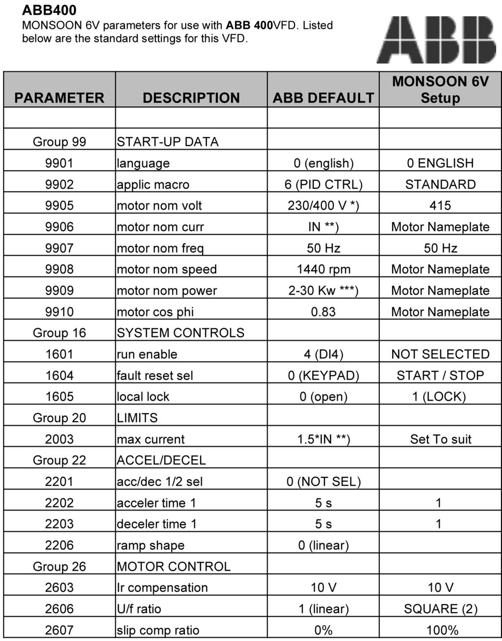
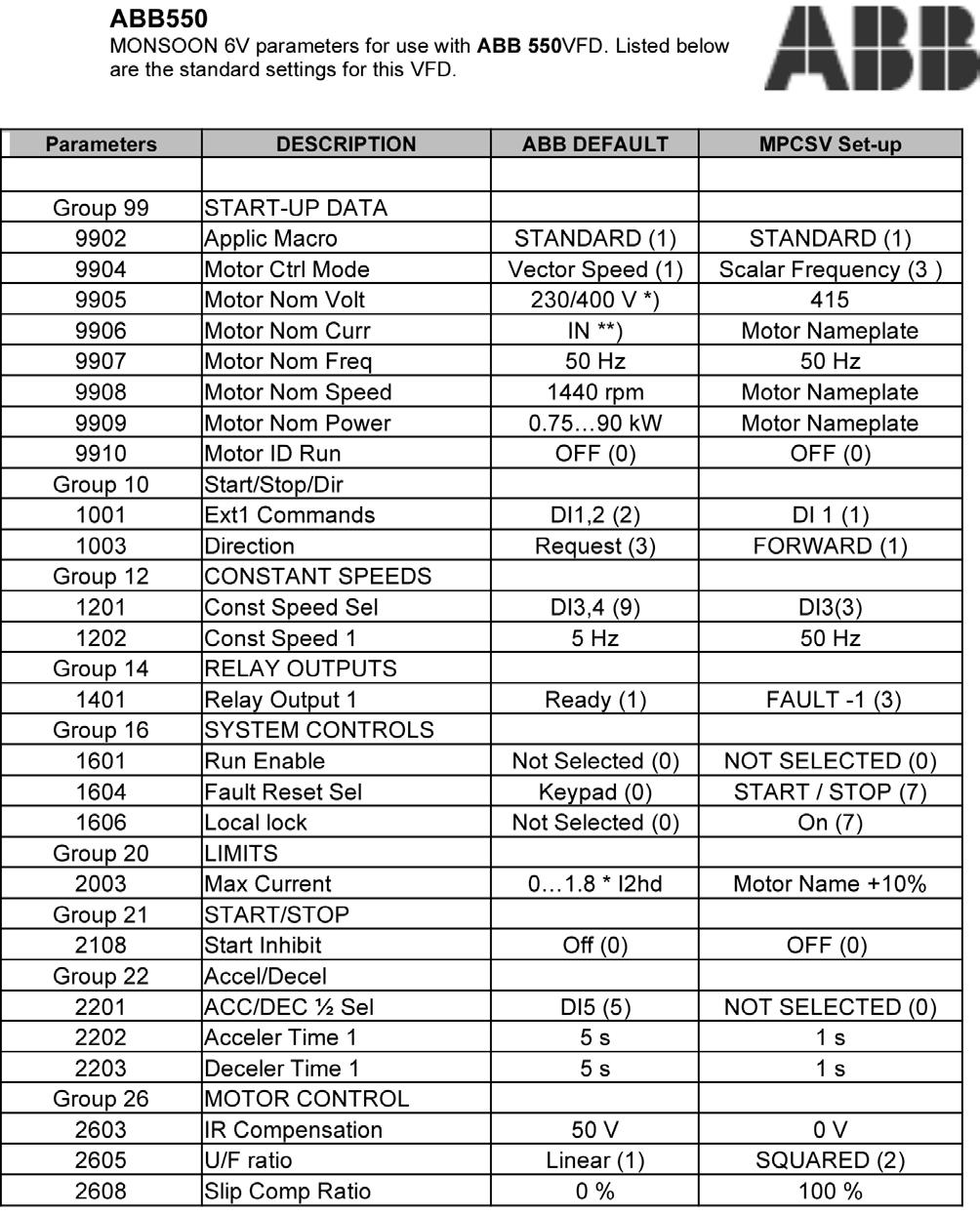
54 To adjust the VFD control parameters the screen on the front of the VFD must be accessed. To scroll between adjustments press the MENU key to gain access to the menu headings. To obtain access to the menus press ENTER and scroll to the relevant menu To edit the items press ENTER. To modify settings hold down the UP or DOWN keys. VFD Control Panel The ABB must be in remote mode to operate with the MPCSV. To reset defaults change Par to any other setting save it and then change it back to standard. ~ 54 ~
55 ~ 55 ~

56 To adjust the VFD control parameters the screen on the front of the VFD must be accessed. To scroll between adjustments press the MENU key to gain access to the menu headings. To obtain access to the menus press ENTER and scroll to the relevant menu To edit the items press ENTER. To modify settings hold down the UP or DOWN keys. VFD Control Panel LCD Display - Divided into three main areas: Top line - variable, depending on the mode of operation. Middle area - variable, in general, shows parameter values, menus or lists Bottom line - shows current function of the two soft keys, and the clock display, if enabled. Soft key 1 - Function varies and is defined by the text in the lower left corner of the LCD display. Soft key 2 - Function varies and is defined by the text in the lower right corner of the LCD display. Up - Scrolls up through a menu or list displayed in the middle of the LCD display. Increments a value if a parameter is selected. Increments the reference if the upper right corner is highlighted (in reverse video). LOC/REM - Changes between local and remote control of the drive. STOP - Stops the drive Down - Scrolls down through a menu or list displayed in the middle of the LCD display. Decrements a value if a parameter is selected. Decrements the reference. If the upper right corner is highlighted (in reverse video). Help - Displays context sensitive information when the button is pressed. The information displayed describes the item currently highlighted in the middle area of the display. START - Starts the drive To reset defaults change Par to any other setting save it and then change it back to standard. ~ 56 ~
57 Danfoss VLT6000 MONSOON 6V parameters for use with Danfoss VLT6000VFD. Listed below are the standard settings for this VFD. To reset the VLT6000 to factory settings:- 1. Power down system. 2. On power up depress Display Mode, Change data & OK ~ 57 ~


58 Control unit LCP (Local Control Panel) The front of the frequency converter features a control panel - LCP(Local Control Panel). This is a complete interface for operation and programming of the frequency converter. The control panel is detachable and can - as an alternative be installed up to 3 metres away from the frequency converter, e.g. on the front panel, by means of a mounting kit option. The functions of the control panel can be divided into five groups: 1. Display 2. Keys for changing display mode 3. Keys for changing program parameters 4. Indicator lamps 5. Keys for local operation All data are indicated by means of a 4-line alphanumeric display, which, in normal operation, is able to show 4 operating data values and 3 operating condition values continuously. During programming, all the information required for quick, effective parameter Setup of the frequency converter will be displayed. As a supplement to the display, there are three indicator lamps for voltage (ON), warning (WARNING) and alarm (ALARM), respectively. All frequency converter parameter setups can be changed immediately via the control panel, unless this function has been programmed to be Locked [1] via parameter 016 Lock for data change or via a digital input, parameters Data change lock. Control keys for parameter setup The control keys are divided into functions. This means that the keys between display and indicator lamps are used for parameter setup, including selecting the display indication during normal operation. [DISPLAY MODE] is used for selecting the indication mode of the display or when returning to the Display mode from either the Quick menu or the Extend menu mode. ~ 58 ~
59 Altivar 28 MONSOON 6V parameters for use with Schneider Altivar 28VFD. Listed below are the standard settings for this VFD ~ 59 ~
60 SPECIFICATIONS ~ 60 ~


61 DIMENSIONS Standard Monsoon 6V Enclosure sizes W x H x D Monsoon 6V with Backup VFD ~ 61 ~


62 Standard Monsoon 6V - Danfoss VFD Option Monsoon 6V - On VFD Per Pump Option ~ 62 ~
Monsoon3V+ Multiple Pump VFD Control System. Please pass these instructions on to the operator of this equipment.
 Monsoon3V+ Multiple Pump VFD Control System Please pass these instructions on to the operator of this equipment. INTRODUCTION MONSOON 3V+ Pump Controller The MONSOON 3V+ pump control system is a fully
Design Envelope Booster. Sequence of operation
 Design Envelope Booster Sequence of operation File No: 62.835 Date: february 11, 2015 Supersedes: 62.835 Date: july 11, 2014 sequence of operation Design Envelope Booster 2 general The packaged domestic
BUBBLER CONTROL SYSTEM
 BUBBLER CONTROL SYSTEM Description: The HDBCS is a fully automatic bubbler system, which does liquid level measurements in water and wastewater applications. It is a dual air compressor system with, air
Touch Screen Guide. OG-1500 and OG Part # T011
 Touch Screen Guide OG-1500 and OG-2000 Part # 9000000.T011 Effective 11/2010 External View Internal View 1. Transducer Banks 2. Oxygen Sensor 3. PLC These are the two manifolds with three (3) transducers
CP3R Quick Start Manual
 RUN MON PRM PU EXT NET RUN D700 3 200V RUN MON PRM PU EXT NET RUN D700 3 200V CP3R Quick Start Manual for Constant Pressure Applications This CP3R Drive has been factory pre-programmed for your specific
CPN1 Quick Start Manual
 RUN MON PRM PU EXT NET RUN RUN MON PRM PU EXT NET RUN CPN1 Quick Start Manual for Constant Pressure Applications This CPN1 Drive has been factory pre-programmed for your specific pressure control application.
COMPRESSOR PACK SUCTION CONTROLLER TYPE: LP41x
 Electrical Installation Requirements Care should be taken to separate the power and signal cables to prevent electrical interference and possible damage due to inadvertent connection. SUPPLY E L N LN2
ACV-10 Automatic Control Valve
 ACV-10 Automatic Control Valve Installation, Operation & Maintenance General: The Archer Instruments ACV-10 is a precision automatic feed rate control valve for use in vacuum systems feeding Chlorine,
Operating instructions Electrical switching facility pco
 Operating instructions Electrical switching facility pco from software version V1.33 on TABLE OF CONTENTS 1. Before you start... 4 1.1 Brief description... 4 1.2 Using this manual... 4 2. pco integrated
CCT-7320/ROC-2313 Reverse Osmosis Controller
 CCT-7320/ROC-2313 Reverse Osmosis Controller 1 General The instrument is a combined control instrument of a reverse osmosis controller and an on-line conductivity instrument. It can perform the operation
1 STARTUP Overview Buttons Basics of Control Resetting Faults and Alarms OPERATION...
 Operation & Service Manual 940126-0002 pco 3 Programmable Logic Controller Contents 1 STARTUP...1 1.1 Overview... 1 1.1.1 Buttons... 1 1.1.2 Basics of Control... 1 1.2 Resetting Faults and Alarms... 2
BUBBLER CONTROL SYSTEM
 BUBBLER CONTROL SYSTEM Description: The LDBCS is a fully automatic bubbler system, which does liquid level measurements in water and wastewater applications. It is a dual air compressor system with, air
Reverse Osmosis System Installation Guide and Operation Manual.
 Reverse Osmosis System Installation Guide and Operation Manual. Table of Contents 1 Introduction...2 2 Installation...3 2.1 Feed water connection...3 2.2 Permeate and concentrate plumbing...3 2.3 Electrical
KELCO F60 DIGITAL PUMP CONTROLLER
 KELCO F60 DIGITAL PUMP CONTROLLER PROGRAMMING INSTRUCTIONS KELCO Engineering Pty Ltd Sydney Australia www.kelco.com.au Table Of Contents Introduction 1 Programming the Controller 2 F60 Modes and Functions,
Installation, Operation and Maintenance Instructions for Electronically Controlled Pressurisation Units
 Installation, Operation and Maintenance Instructions for Electronically Controlled Pressurisation Units Models: EPS Single Pump EPT Twin Pump EPS-HP EPT-HP Single Pump High Pressure Twin Pump High Pressure
CONTROL LOGIC DESCRIPTION DOCUMENT IC-410ND
 Configuration # : 41G20F0 CONTROL LOGIC DESCRIPTION DOCUMENT IC-410ND Input/output table: Inputs Qty Outputs Qty Inside Temperature Probe 3 Inflatable Balloon 8 Chimney Temperature Probe 1 Chimney Activator
USER MANUAL. Intelligent Diagnostic Controller IDC24-A IDC24-AF IDC24-AFL IDC24-F IDP24-A * IDP24-AF * IDP24-AFL * IDP24-F * 1/73
 USER MANUAL Intelligent Diagnostic Controller IDC24-A IDC24-AF IDC24-AFL IDC24-F IDP24-A * IDP24-AF * IDP24-AFL * IDP24-F * *) Require software ID: DID-SW-001 1/73 Table of contents 1 General... 3 1.1
Hydro-Control V User Guide
 Hydro-Control V User Guide Hydronix Part no: HD0193 Version 2.3.0 Revision date: July 2006 1 COPYRIGHT Neither the whole or any part of the information contained in nor the product described in this documentation
Controlling the prefeeder
 Controlling the prefeeder A prefeeder is a modulating device of some kind, controlling the material flow into the belt feeder infeed. You need it for three reasons: 1. The material can not be sheared at
MP15 Jockey Pump Controller
 Setup and Operating Instructions MP15 Jockey Pump Controller This manual provides general information, installation, operation, maintenance, and system setup information for Metron Model MP15 Jockey Pump
A4s Operation Manual
 A4s Operation Manual Safety Instruction Please read this manual carefully, also with related manual for the machinery before use the controller. For installing and operating the controller properly and
PART 5 - OPTIONS CONTENTS 5.1 SYSTEM EXPANSION 5-3
 PART 5 - OPTIONS CONTENTS Para Page 5.1 SYSTEM EXPANSION 5-3 5.2 SENSORS 5-3 5.2.1 Trim Angle Sensor 5-3 5.2.2 Mast Rotation Sensor 5-3 5.2.3 Heel Angle Sensor 5-3 5.2.4 Barometric Pressure Sensor 5-3
REASONS FOR THE DEVELOPMENT
 7 Series 7 Series +24VDC VDC OUTPUT MICROPROCESS. E P IN EXH OUT 7 Series 7 ø,8 8 7 Series 9 5 8 9 7 Series Display features The proportional regulator has a 3 /2 digit display and a three-pushbutton
VARIOspeed 3R User Manual
 VARIOspeed 3R User Manual This VARIOspeed 3R control panel is designed to provide constant pressure control for your pumping system. Should you need to make minor adjustments, please consult the parameter
Roller AC Servo System
 Safely Instruction Roller AC Servo System HMI-15 User Manual Please read this manual carefully, also with related manual for the machinery before use the controller. For installing and operating the controller
ECL Comfort 110, application 131 (valid as of software version 2.00)
") Operating Guide ECL Comfort 110, application 131 (valid as of software version 2.00) English version www.danfoss.com How to navigate? Adjust temperatures and values. Switch between menu lines. Select /
Operating Guide ECL Comfort 110, application 131 (valid as of software version 2.00) English version www.danfoss.com How to navigate? Adjust temperatures and values. Switch between menu lines. Select /
GATE 2 Part No
 PAGE 1 GATE 2 Part No. 23001125 SWING GATE CTROLLER INSTALLATI GUIDE Page 2 GATE 2 Code No. 23001125 Electronic Control Board for use with SEA Hydraulic or Electro-mechanical swing gate operators (without
Aquavar SOLO 2 Frequently Asked Questions
 Aquavar SOLO 2 Frequently Asked Questions How do I size the Aquavar SOLO 2 for the appropriate pump/motor combination? Can I use a 208 Volt motor? Can I run the Aquavar SOLO 2 up to 80HZ? What are the
A4 Operation Manual. Fig.1-1 Controller Socket Diagram
 A4 Operation Manual Safety Instruction Please read this manual carefully, also with related manual for the machinery before use the controller. For installing and operating the controller properly and
Temperature Controller CC24-7 ULTRA USER S MANUAL Legion Dr. Mason, MI USA October 2010 Ph. (517) Fax (517)
 Fax (517)") Temperature Controller USER S MANUAL Aerotech, Inc. FORM: QM1387 4215 Legion Dr. Mason, MI 48854-1036 USA October 2010 Ph. (517) 676-7070 Fax (517) 676-7078 FOR CUSTOMER USE Enter the serial number located
Temperature Controller USER S MANUAL Aerotech, Inc. FORM: QM1387 4215 Legion Dr. Mason, MI 48854-1036 USA October 2010 Ph. (517) 676-7070 Fax (517) 676-7078 FOR CUSTOMER USE Enter the serial number located
Standard Chiller 1/4 compressors Manual version: /10/96
 Application program for Macroplus II Standard Chiller 1/4 compressors Manual version: 1.4-18/10/96 Program code: EP000ECH02 Rif.: 68EM Contents 0$,1)($785(6 HARDWARE...2 FUNCTIONS OF THE SYSTEM...3 PROTECTIONS...3
Sequence of Operations
 MAGNUM Condensing Unit Software 5580 Enterprise Pkwy. Fort Myers, FL 33905 Office: 239-694-0089 Fax: 239-694-0031 Sequence of Operations MAGNUM Chiller V8 software www.mcscontrols.com MCS Total Solution
A TECHNICAL REFERENCE
 A TECHNICAL REFERENCE FOR CAREL DCM CONTROLLERS DIGITAL COMPRESSOR MODULE CANADIAN HEAD OFFICE AND FACTORY USA HEAD OFFICE AND FACTORY CANADIAN EASTERN FACTORY 1401 HASTINGS CRES. SE CALGARY, ALBERTA T2G
Guida parametri EVD 200. Manuale d'uso User manual
 Guida parametri EVD 200 Manuale d'uso User manual Contents 1. EVD200 parameter guide... 15 1.1 Driver configuration... 15 1.2 Parameter configuration... 15 1.3 Alarms enable/delay (COMM)... 17 1. EVD200
CHILLER CONTROL PANEL PROGRAMMING AND DATA ACCESS
 Micropanel CHILLER CONTROL PANEL PROGRAMMING AND DATA ACCESS STATUS DISPLAY SETPOINTS CLOCK DISPLAY INFORMATION KEYS 00407VIP PRINT ON / OFF PROGRAM & SETUP KEY DISPLAY AND STATUS INFORMATION KEYS Status
LENNOX SLP98UHV DIAGNOSTIC CODES
 Code Status of Equipment Action required to clear and recover - Idle mode (Decimal blinks at 1 Hertz -- 0.5 second ON, 0.5 second OFF) A Cubic feet per minute (cfm) setting for indoor blower (1 second
SPECIFICATIONS APCEPH1
 APCEPH1 ph CONTROLLER SPECIFICATIONS APCEPH1 Input voltage 120 Volts AC Maximum amperage 14.5 amps @ 120 VAC ph Accuracy +/- 0.2 ph ph Control range Adjustable 4.5 8.5 ph Weight < 1 lbs Dimensions 3" x
Standard 1/4 compressor chiller/heat pump with heating recovery Manual version: /02/97
 Application program for Macroplus II Standard 1/4 compressor chiller/heat pump with heating recovery Manual version: 2.2-06/02/97 Program code: EP000EPDC0 Rif.: 17EM INDEX MAIN FEATURES...2 Hardware Description...2
M2110P SMART PRESSURE GAUGE USER S MANUAL
 M2110P SMART PRESSURE GAUGE USER S MANUAL Meriam s M2110P Smart Pressure Gauge is a microprocessor-based pressure sensing device. The various ranges available provide measurement of differential (dry/dry
Datasheet: K-30 ASCII Sensor
 Datasheet: K-30 ASCII Sensor The K30 ASCII sensor is a low cost, infrared and maintenance free transmitter module intended to be built into different host devices that require CO2 monitoring data. The
Master Control Systems, Inc. Variable Speed Fire Pump Controllers
 Master Control Systems, Inc. Variable Speed Fire Pump Controllers Meets NFPA 20-2019 UL/FM Listed and Approved for fire protections * Pressure Limiting Control * Suction Limiting Control Why Variable Speed?
SR-242 USER S GUIDE. Table of Contents
 User s Guide gfhf Table of Contents 1. Introduction...3 2. Faceplate...3 2.1 Parameter List...3 2.2 Parameter Buttons ( and )...4 2.3 Function Buttons ( and )...4 2.4 LED Status Window...4 2.5 Value Setting
SINGLE VALVE WITH LOW-FLOW BYPASS
 CONTROL VALVES Pressure Reducing Valve Sizing Guide Sizing pilot operated reducing valves is not a complicated process. It starts with determining requirements and following these guidelines in valve size
Revision 1 AIR & WATER COOLED LIQUID CHILLERS MICRO BASED CONTROL SYSTEM WITH IPUII
 YLAA0189SE-YLAA0485SE YLAA0195HE-YLAA0515HE YLAE0195SE-YLAE0490SE YLAE0195HE-YLAA0510HE YLAE0195LT-YLAE0490LT YCWL0240SE - YCWL0395SE YCWL/YCRL0200HE - YCWL/YCRL0610HE OPERATING INSTRUCTION Revision 1
Micro Environmental Control Systems Woda Sci Sump Sprinkler and Home Water Control System Manual Contents
 User Manual 1 Micro Environmental Control Systems Woda Sci Sump Sprinkler and Home Water Control System Manual Contents Powering Up... 3 Navigating thru the menus.... 3 Main Menu Option... 4 Main Menu
OC Panel High Limit Aquastat Kit, Manual Reset p/n
 OC Panel High Limit Aquastat Kit, Manual Reset p/n 233202 Instruction Sheet APPLICATION The OC (Option Control) Panel High Limit Aquastat Kit provides electronic temperature sensing in a UL limit-rated
DeeterFlow Automatic Liquid Dispenser
 DeeterFlow Automatic Liquid Dispenser Table of Contents 1. Introduction... 3 2. Installation... 4 3. Volume Accuracy... 5 4. Operator Controls... 5 5. Operating States... 6 5.1 Power-up... 6 5.2 Ready
WATER CONTROL SYSTEM QUICK START
 SETTINGS MENU SYSTEM OPTIONS WATER LEVEL BAR GRAPH 3 DS SPRAY ON/OFF CS SPRAY ON/OFF BEACON WATER CONTROL SYSTEM QUICK START WWW.GFWORLDWIDE.COM +1 (208) 664-9291 SERVICE@GFWORLDWIDE.COM DISPLAY SCREEN
Advanced Pump Control for Irrigation Applications
 Advanced Pump Control for Irrigation Applications Paul Nistler VFD Applications Engineer And Julian Atchia Director of Research and Development SJE Rhombus 22650 County Hwy 6 Detroit Lakes MN 56502 Executive
JOLLY2. Installation user s manual. 6 different operating modes selectable. version 3.3. DATA TO BE FILLED OUT BY THE INSTALLER (Page 1)
") ENGLISH ENGLISH ENGLISH ENGLISH Installation user s manual Warning! electrical scheme modified JANUARY 2005 version 3.3 JOLLY2 DATA TO BE FILLED OUT BY THE INSTALLER (Page 1) 6 different operating modes
ENGLISH ENGLISH ENGLISH ENGLISH Installation user s manual Warning! electrical scheme modified JANUARY 2005 version 3.3 JOLLY2 DATA TO BE FILLED OUT BY THE INSTALLER (Page 1) 6 different operating modes
CONSOLE-320 ENGLISH. 230A: CONSOLE-320 with cable data output Item 230B: CONSOLE-320 with cable + wireless radio data output
 CONSOLE-320 Item 230A: CONSOLE-320 with cable data output Item 230B: CONSOLE-320 with cable + wireless radio data output Table of contents 1. INTRODUCTION...2 1.1 Power supply...2 1.2 Connections...2 1.3
AHE58/59 AC Servo System
 AHE58/59 AC Servo System HMI-12 User Manual Safely INstruction Please read this manual carefully, also with related manual for the machine head before use. For perfect operation and safety, installing
EZ Boom 2010 System for the EZ Guide 500 Lightbar Triangle Ag Services Users Guide
 EZ Boom 2010 System for the EZ Guide 500 Lightbar Triangle Ag Services Users Guide Parts of the Controller (For details on the parts of the EZ Boom controller refer to Appendix F) Status Indicator Rate
Using Modbus Protocol with the ALTUS Net Oil Computer. Instruction Manual
 Using Modbus Protocol with the ALTUS Net Oil Computer Instruction Manual November 2000 Using Modbus Protocol with the ALTUS Net Oil Computer Instruction Manual November 2000 For technical assistance,
WARNING FOR YOUR SAFETY
 ! OWNER S MANUAL Power Alert AquaLink TRI Controller H0389100 REV A WARNING FOR YOUR SAFETY - This product must be installed and serviced by a licensed electrician in accordance with AS/NZ 3000-2007 and
Model 130M Pneumatic Controller
 Instruction MI 017-450 May 1978 Model 130M Pneumatic Controller Installation and Operation Manual Control Unit Controller Model 130M Controller is a pneumatic, shelf-mounted instrument with a separate
User Manual. asense VAV. CO 2 / temperature sensor with built-in general purpose controller
 Gas and Air Sensors User Manual asense VAV CO / temperature sensor with built-in general purpose controller General The IAQ-sensor product asense VAV is used to measure indoor air carbon dioxide concentration
Copeland Discus with CoreSense Diagnostics January 2011
 Copeland Discus with CoreSense Diagnostics January 2011 Slide 1 1/27/2011 5:48 PM Discus with CoreSense Diagnostics Case Studies Supermarket In Columbus, Ohio Saves $4,500 With Discus with CoreSense Diagnostics
Master Control Systems, Inc. Variable Speed Fire Pump Controllers
 Master Control Systems, Inc. Variable Speed Fire Pump Controllers Meets NFPA 20-2013 UL/FM Listed and Approved for fire protections 1 Why Variable Speed? Huge Sprinkler System and Standpipe Cost Savings
Stand-Alone Bubble Detection System
 Instruction Sheet P/N Stand-Alone Bubble Detection System 1. Introduction The Bubble Detection system is designed to detect air-bubble induced gaps in a bead of material as it is being dispensed. When
Instructions and Advices to use the electronic controller Logik 31-S
 Instructions and Advices to use the electronic controller Logik 31-S ORIGINAL INSTRUCTIONS 01/08/12 Rev. 0 1 LOGIKA CONTROL s.r.l. Via Garibaldi, 83/a 20054 NOVA MILANESE MI ITALY Tel.: +39 0362 37001
CHEMICAL ENGINEERING LABORATORY CHEG 239W. Control of a Steam-Heated Mixing Tank with a Pneumatic Process Controller
 CHEMICAL ENGINEERING LABORATORY CHEG 239W Control of a Steam-Heated Mixing Tank with a Pneumatic Process Controller Objective The experiment involves tuning a commercial process controller for temperature
INSTRUCTION MANUAL STATION CONTROLLER SC100 MOTOR PROTECTION ELECTRONICS, INC.
 INSTRUCTION MANUAL STATION CONTROLLER SC100 MOTOR PROTECTION ELECTRONICS, INC. 2464 Vulcan Road, Apopka, Florida 32703 Phone: (407) 299-3825 Fax: (407) 294-9435 Revision Date: 2-12-07 STATION CONTROLLER
Electronic Commissioning Unit. Instructions
 Electronic Commissioning Unit Instructions 1. The Comdronic AC6 Electronic Commissioning Unit 2. Health and Safety 3. Description of Unit 4. Connection and Set-up Procedure 5. Menu System a. Main Menu
TANK MANAGER FOR TWO TANKS OPERATING MANUAL. 10/31/11 C-More T6C L color touch panel
 TANK MANAGER FOR TWO TANKS OPERATING MANUAL 10/31/11 C-More T6C L color touch panel 1 TABLE OF CONTENTS GENERAL...3 INSTALLATION...4 STONE TEST PROCEDURE...7 OPERATIONAL SUMMARY...7 AUTO CARBONATION...10
User manual CF8-D/W-IN
 User manual CF8-D/W-IN General The sensor CF8-D/W-IN is used to measure the carbon dioxide concentration inside incubators. All functions can be modified from a PC with the communication cable. UMA 48
User s manual VCI07. For variable speed compressors ed00. Applicable as of Version 12. Bar PSI C F
 User s manual EN VCI07 For variable speed compressors 62 205 930 11 ed00 Applicable as of Version 12 Bar PSI C F Table of contains 1 - GENERAL INFORMATION...3 2 - USER INTERFACE...3 2.1 DISPLAYS...3 2.2
Measuring range Δp (span = 100%) Pa
 Pa") 4.4/ RLE 5: Volume-flow controller, continuous How energy efficiency is improved Enables demand-led volume flow control for the optimisation of energy consumption in ventilation systems. Areas of application
4.4/ RLE 5: Volume-flow controller, continuous How energy efficiency is improved Enables demand-led volume flow control for the optimisation of energy consumption in ventilation systems. Areas of application
4HS Submersible Pumps
 4HS Submersible Pumps Installation and Operating Manual man4hs_12_eng Index 1. Introduction of the 4HS submersible pumps range... 3 2. Safety Instructions... 4 3. Stocking conditions... 4 4. Packing content...
SAPCON. User Manual. Capacitance Continuous Level Indicator. . Introduction. . General Description. . Principle of Operation. .
 User Manual Capacitance Continuous Level Indicator Comprehensive User s Manual. Introduction. General Description. Principle of Operation. Specifications. Connection Diagrams. Quick Calibration Chart.
Specifications and information are subject to change without notice. Up-to-date address information is available on our website.
 www.smar.com Specifications and information are subject to change without notice. Up-to-date address information is available on our website. web: www.smar.com/contactus.asp LD302 - AssetView HMI LD302
Declining Weight Blending System Quick Start Manual E Main St Marshall, IL Phone: Fax: Website:
 Declining Weight Blending System Quick Start Manual 12285 E Main St Marshall, IL 62441 Phone: 217-826-6352 Fax: 217-826-8551 Website: www.yargus.com P a g e 2 MAIN SCREEN The MAIN SCREEN on the cover page
Control units. Installation and operating instructions Series: Megacontrol
 Control units Installation and operating instructions Series: Megacontrol Table of Contents 1 Introduction 1.1 Preface... 4 1.2 Icons and symbols... 4 2 Identification, service and technical support 2.1
OFI MODEL 20 CONSTANT SPEED BLENDER INSTRUCTIONAL MANUAL
 OFI MODEL 20 CONSTANT SPEED BLENDER INSTRUCTIONAL MANUAL OPERATING INSTRUCTIONS OFI MODEL 20 CONSTANT SPEED BLENDER GENERAL OFI's Model 20 Constant Speed Blender was designed to prepare well cements for
These variables can be accessed by holding the UP button for 5 seconds.
 PureSilk Chromatalyzer QUICK SETUP GUIDE Read Owners Manual before operating this unit Only electrically qualified and authorized persons are permitted to service this unit Warranty is void if non-genuine
MICRO BASED CONTROL SYSTEM YLCS-SA/HA/AA YAES-SA 2 System YAES-SA 3 System YAES-DSA 4 System
 MICRO BASED CONTROL SYSTEM YLCS-SA/HA/AA YAES-SA 2 System YAES-SA 3 System YAES-DSA 4 System OPERATION INSTRUCTION YLCS-SA/HA/AA: R134a - Software Version B.A05.01.01 and higher version levels YAES-SA
UBEC 1AT. AUTO TANK Fill System Installation, Operation, & Setup Instructions
 Document Number: XE-ATA5PM-R1A UBEC 1AT AUTO TANK Fill System 08899155 Installation, Operation, & Setup Instructions Rev170906-EB-FRC PHYSICAL: 1302 WEST BEARDSLEY AVE ELKHART, IN 46514 WWW.ELKHARTBRASS.COM
Digital Vacuum Regulator
 Temperature Control for Research and Industry Digital Vacuum Regulator User s Manual Model 300 INDEX SECTION PAGE 1. QUICK OPERATING INSTRUCTIONS........................... 3 Safety Notices.................................................
ECONORESS ELECTRONIC EPS & EPT - ENHANCED PRESSURISATION SET INSTALLATION OPERATION & MAINTENANCE DOCUMENTATION
 ECONORESS ELECTRONIC EPS & EPT - ENHANCED PRESSURISATION SET INSTALLATION OPERATION & MAINTENANCE DOCUMENTATION OCT2010 STOKVIS ENERGY SYSTEMS 96R WALTON ROAD EAST MOLESEY SURREY KT8 0DL TEL: 020 87833050
Installation, Operation and Maintenance Instructions for Electronically Controlled Pressurisation Units Digital Range
 Installation, Operation and Maintenance Instructions for Electronically Controlled Pressurisation Units Digital Range Models: DS 126 Single Pump / Single System DT 126 Twin Pump / Single System DS 160
Built-in Purge Control Functions
 Built-in Purge Control Functions Why clean a sensor? As the velocity sensor was calibrated clean, operating it clean also preserves the best calibration. Any build up of material on a thermal sensor tends
NOTICE. Issued: February 12, 2010 AO# Dundas Street West, Oakville, ON CANADA Phone: (905) Fax: (905)
 Fax: (905)") NOTICE The enclosed materials are considered proprietary property of GE Water & Process Technologies. No assignments, either implied or expressed, of intellectual property rights, data, know how, trade
NOTICE The enclosed materials are considered proprietary property of GE Water & Process Technologies. No assignments, either implied or expressed, of intellectual property rights, data, know how, trade
HEAT-TIMER CORP. 20 NEW DUTCH LANE FAIRFIELD, NEW JERSEY TEL. (973) FAX (973) INSTALLATION & OPERATION MANUAL TABLE OF CONTENTS
 FAX (973) INSTALLATION & OPERATION MANUAL TABLE OF CONTENTS") HEAT-TIMER CORP. 20 NEW DUTCH LANE FAIRFIELD, NEW JERSEY 07004 TEL. (973)575-4004 FAX (973)575-4052 INSTALLATION & OPERATION MANUAL MODEL MOD-4 TABLE OF CONTENTS Control Panel...2 MOD-4 Overview...4 Installation...6
HEAT-TIMER CORP. 20 NEW DUTCH LANE FAIRFIELD, NEW JERSEY 07004 TEL. (973)575-4004 FAX (973)575-4052 INSTALLATION & OPERATION MANUAL MODEL MOD-4 TABLE OF CONTENTS Control Panel...2 MOD-4 Overview...4 Installation...6
CDS-2000 CO 2 Sensor Verification, Calibration, and Troubleshooting Bulletin
 Electronic Control Manual 216 Sensors and Stats Section S Technical Bulletin CDS-2000 Issue Date 0393 CDS-2000 CO 2 Sensor Verification, Calibration, and Troubleshooting Bulletin Introduction 3 Pre-Verification
FRDS GEN II SIMULATOR WORKBOOK
 FRDS GEN II SIMULATOR WORKBOOK Trotter Control Inc 2015 Document# Revision Revised 9001-0038 FRDS GEN II Simulator Workbook E 02/15/2015 by DC FRDS GEN II Simulator Workbook This workbook is a follow-on
Position Controller PS312P_LCD_v2.2
 Position Controller PS312P_LCD_v2.2 INSTRUCTION MANUAL Hymark Ltd. 427 Bark Cove Owensboro, KY 4233 (27) 683-35 Fax (27) 683-25 www.kentuckygauge.com 1. FUNCTIONS OF THE DISPLAYS...3 2. FUNCTIONS OF THE
Race Screen: Figure 2: Race Screen. Figure 3: Race Screen with Top Bulb Lock
 Eliminator Competition Stand Alone Mode - Instruction Manual Main Menu: After startup, the Eliminator Competition will enter the Main Menu. Press the right/left arrow buttons to move through the menu.
Scoreboard Operator s Instructions MPC Control
 Scoreboard Operator s Instructions MPC Control Some features on the keyboard overlay may not be included on the particular model being operated. Since 1934 Retain this manual in your permanent files 1/21/2011
Operating instructions Safety Rope Emergency Stop Switches ZB0052 / ZB0053 ZB0072 / ZB0073
 Operating instructions Safety Rope Emergency Stop Switches UK ZB0052 / ZB0053 ZB0072 / ZB0073 7390878 / 02 03 / 2011 Contents 1 Safety instructions...3 2 Installation / set-up...4 2.1 Applications...4
Application Block Library Fan Control Optimization
 Application Block Library Fan Control Optimization About This Document This document gives general description and guidelines for wide range fan operation optimisation. Optimisation of the fan operation
ATL R/V Atlantis AUXILIARY PLANT OPERATION APPENDIX OPERATING PROCEDURES
 110 AIR CONDITIONING CHILLED WATER PLANT 1. Ensure power to water chiller controller and all fan coil unit controllers is on 2. Ensure chilled water expansion tank level is at its proper level 3. Ensure
GRUNDFOS DATA BOOKLET. Hydro Solo-E. Complete pressure boosting systems 50/60 Hz
 GRUNDFOS DATA BOOKLET Complete pressure boosting systems 5/6 z Contents Product data Performance range 3 Operating conditions Inlet pressure Type key Product range 5 Construction 5 Installation 5 Mechanical
Quick Start Setup Instructions for Raven LRC & AgXcel Harness for NH3 Profile plus GX40 Synergist
 PLEASE NOTE: Your setup may vary. These screen shots represents a typical AgXcel Liquid Fertilizer System setup. See the Raven LRC Operator s Manual for safety information and additional setup and operating
CF8-W-Disp-CO. User manual. CO 2 / CO sensor with built-in general purpose controller
 User manual CF8-W-Disp-CO CO 2 / CO sensor with built-in general purpose controller General The IAQ-sensor product CF8-W-Disp-CO is used to measure indoor air carbon dioxide and carbon monoxide concentrations.
Exercise 8. Closed-Loop Pressure Control, Proportional-Plus-Integral Mode EXERCISE OBJECTIVE
 Exercise 8 Closed-Loop Pressure Control, EXERCISE OBJECTIVE To understand open and closed-loop pressure control; To learn how to sense the pressure in a pneumatic circuit; To control the pressure in a
TorMinal. Operating instructions V OCE-Rev.L_EN
 TorMinal Operating instructions 1-138 3800-20310V001-112016-0-OCE-Rev.L_EN Table of contents General Information... 4 Symbols... 4 General safety instructions... 4 Safety information for batteries... 4
CONTROL and INSTRUMENTATION
 CONTROL and INSTRUMENTATION COURSE 500: 5 DAYS: Max 8 Candidates This course covers the key aspects of current instrumentation and process control technology and is designed to enable maintenance personnel
Ultima. X Series Gas Monitor
 Ultima X Series Gas Monitor Safety Manual SIL 2 Certified " The Ultima X Series Gas Monitor is qualified as an SIL 2 device under IEC 61508 and must be installed, used, and maintained in accordance with
Alimak Lift Control, ALC II User s Manual
 Alimak Lift Control, ALC II User s Manual This manual is only applicable if the manufacturing number indicated below corresponds to the manufacturing number stamped on the identification sign of the equipment.
WMC Magnetic Bearing Compressor Chillers
 Operating and Maintenance Manual OMM WMC-2 OITS Group: Chiller Part Number: 331374701 Effective: March 2005 Supersedes: OM WMC-1 WMC Magnetic Bearing Compressor Chillers Model WMC 035T 50/60 Hertz OITS