THE CENTER OF PRESSURE EXPERIMENT
|
|
|
- Corey Mosley
- 5 years ago
- Views:
Transcription
1 THE CENTER OF PRESSURE EXPERIMENT
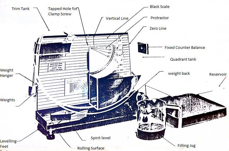
2 1. INTRODUCTION The apparatus permits the moment due to the total fluid thrust on a wholly or partially submerged plane surface to be measured directly and compared with theoretical analysis. Provision is made for varying the inclination of the plane surface subjected to fluid pressure so that the general case may be studied. 1.1 DESCRIPTION OF APPARATUS (ref fig 1) Water is contained in a quadrant of a semi-circular Perspex tank assembly which is allowed to roll on a smooth surface. The cylindrical sides of the quadrant have their axes coincident with the center of rotation of the tank assembly, and therefore the total fluid pressure acting on these surfaces exerts no moment at that center. The only moment present is that due to fluid pressure acting on the plane surface. This moment is measured experimentally by applying weights to a weight hanger mounted on the semi-circular assembly on the opposite side to the quadrant tank. A second tank, situated on the same side of the assembly as the weight hanger, provides a trimming facility and enables different angles of balance to be achieved. The angular position of the plane and the height of water above it are measured on a protractor scale mounted on the tank and a linear scale on the back panel. The apparatus is completed by base levelling feet and spirit level together with a water reservoir and filling jug. A plate is supplied to protect the rolling surface when the equipment is not in use. 1
3
4 1. Installation and Preparation It is essential that at all times in using this apparatus the ROLLING SURFACE and the ROLLING EDGES of the tank assembly are treated CAREFULLY and are well PROTECTED WHEN STORED. a) Unscrew the clamping screw that secures the hopper to the back panel and hang it behind the unit. Lift the tank assembly and remove the protecting plate from the rolling surface. Clean the rolling surface and rolling edges with a soft cloth or tissue (not provided) and place the hopper gently onto the rolling surface. b) Check that the back scale on the panel lines up so that the zero line passes through the center of rotation and lines up with the 0ᵒ line on the hopper. The back panel is secured by three screws at the rear. To adjust its position, slacken the screws, move the panel in the slotted holes and retighten. c) Level the base plate by screwing the adjustable feet and observing the spirit level. d) After completing the experiment, the apparatus can be emptied into the reservoir tank in the following way: i) Pour the contents of the quadrant tank over the edge to which the fixed counter balance is attached. The water in the trim tank is contained by a partial lid during this operation. ii) Having emptied the quadrant tank, the trim tank can now be emptied into the reservoir. e) On completion of the experiment, replace the protective plate and affix the tank assembly to the back plate. f) The apparatus should be cleaned regularly using a detergent solution or any good quality glass cleaner. When cleaning, care should be taken to ensure that no traces of grit or any hard abrasive materials are present on the cloth used. Do not use any materials containing man-made fibers as these will scratch the Perspex.
5 4 Fig Schema of Centre of Pressure Apparatus
6 THEORY.1 Definition of center of pressure Center of Pressure may be defined as the point in a plane at which the total fluid thrust can be said to be acting normal to that plane.. Analysis The following analysis applies to the condition of a plane surface at various angles when it is wholly or partially submerged in a fluid. Let breadth (width) of quadrant = B And weight per unit volume = ω Referring to fig, consider an element at start depth y, width δy. Therefore, force on element δf = ω (y cos θ - h) B dy And moment of force on element about 0 = ω B ( y cos θ h) y δ y Therefore, total moment about 0 = M = w B (cosθy² - h y) dy Case I Plane fully submerged Limits R1 and R R M=ωB (cosθy² - hy) dy R1 M = ωb [ cosθy R hy + c] R1 M = ωbcosθ(r R 1 ) ωb(r R 1 )h This equation is of the form of y = mx + C. A plot of M against h will yield a straight line graph of gradient ωb(r R 1 ). The value of ω can now be calculated. 5
7 Case II Plans partially submerged Limits R and h sec θ R Hence M = ωb (cosθy hy)dy hsecθ R ωb cosθy M = [ hy + c] h sec θ Re-arranging M = ωbcos θ(r h sec θ) M = ωbcosθr ωbcosθr ωbsec θh ωbr h ωbh(r h sec θ) ωbr h + ωbsec θh 6 + ωbsec θh M + ωbr h = ωbsec θh 6 `Obtain ω from case I and plot h against M+ ωbr h + ωbcosθr Fig 4 shows the general form of the graphs expected from this experiment. 6
8 EXPERIMENTAL PROCEDURE Set up the equipment as previously described in section 1.; affix the weight hanger to the cord. The apparatus will now require trimming in order to bring the submerged plane to the vertical (i.e. 0 position). This is achieved by gently pouring water into the trim tank until the desired position is achieved. The protractor on the tank assembly should be read against the zero line on the back scale. Should it be necessary to remove any water, a pipette is supplied which is dipped into the tank and water held by putting a finger on the top of the pipette and transferring the water to the reservoir. Once trimmed, the tank assembly should be set so that the center of the rolling radius lines up with the vertical line on the back panel. This ensures that there is sufficient room on the rolling surface from the tank assembly throughout the tests. Add a 0gm weight to the weight hanger. Pour water into the quadrant tank until a 0 balance is restored. Note the weight and the height reading of the water (h). Repeat the procedure for the full range of weights in steps of 0g. Empty both tanks of water. Again, with the weight hanger alone in position, trim the assembly by gently adding water to the trim tank until a balance at 10 is achieved. Add weights in increments of 0g, restore balance to 10 point and record values for h for the full range of weights. The experiment can then be repeated for 0 and 0. Readings should be tabulated in the form outlined in fig and the results calculated in line with the theory given in section. 7
9 W (gm) M W 9.81 R 10 (Nm) h (mm) h (m) h (m) M + ωbr h (Nm) Note: ω-specific weight->n/m θ Fig Format of results table 8
10 M (Nm) θ = 0 Plane fully submerged h (m) M + wbr (Nm) P Plane partially submerged h (m ) Fig 4 Typical Graphs 9
Hydrostatic Force on a Submerged Surface
 Experiment 3 Hydrostatic Force on a Submerged Surface Purpose The purpose of this experiment is to experimentally locate the center of pressure of a vertical, submerged, plane surface. The experimental
Irrigation &Hydraulics Department lb / ft to kg/lit.
 CAIRO UNIVERSITY FLUID MECHANICS Faculty of Engineering nd Year CIVIL ENG. Irrigation &Hydraulics Department 010-011 1. FLUID PROPERTIES 1. Identify the dimensions and units for the following engineering
FLUID MECHANICS. Fluid Statics BUOYANCY. Fig. Buoyancy CENTER OF BUOYANCY
 FLUID MECHANICS Fluid Statics BUOYANCY When a body is either wholly or partially immersed in a fluid, the hydrostatic lift due to the net vertical component of the hydrostatic pressure forces experienced
1. Air is blown through a pipe AB at a rate of 15 litre per minute. The cross-sectional area of broad
 Keshaw Classes IIT/JEE Medical Classes 5-A 11028 / 9, WEA, Sat Nagar, Karol Bagh New Delhi-110005 Mob:9910915514,9953150192 Ph:011-45660510 E-mail : keshawclasses@gmail.com Web:www.keshawclasses.com Solids
Tutorial 5 Relative equilibrium
 Tutorial 5 Relative equilibrium 1. n open rectangular tank 3m long and 2m wide is filled with water to a depth of 1.5m. Find the slope of the water surface when the tank moves with an acceleration of 5m/s
Student name: + is valid for C =. The vorticity
 13.012 Marine Hydrodynamics for Ocean Engineers Fall 2004 Quiz #1 Student name: This is a closed book examination. You are allowed 1 sheet of 8.5 x 11 paper with notes. For the problems in Section A, fill
BOYLE S / CHARLES LAW APPARATUS - 1m long
 BOYLE S / CHARLES LAW APPARATUS - 1m long Cat: MF0340-101 (combination Boyle s and Charles without mercury) DESCRIPTION: The IEC Boyle's & Charles Law apparatus is a high quality instrument designed to
A NOVEL FLOATING OFFSHORE WIND TURBINE CONCEPT: NEW DEVELOPMENTS
 A NOVEL FLOATING OFFSHORE WIND TURBINE CONCEPT: NEW DEVELOPMENTS L. Vita, U.S.Paulsen, T.F.Pedersen Risø-DTU Technical University of Denmark, Roskilde, Denmark luca.vita@risoe.dk Abstract: A novel concept
Experiment P18: Buoyant Force (Force Sensor)
") PASCO scientific Physics Lab Manual: P18-1 Experiment P18: (Force Sensor) Concept Time SW Interface Macintosh file Windows file Newton's Laws 45 m 300/500/700 P18 P18_BUOY.SWS EQUIPMENT NEEDED CONSUMABLES
PASCO scientific Physics Lab Manual: P18-1 Experiment P18: (Force Sensor) Concept Time SW Interface Macintosh file Windows file Newton's Laws 45 m 300/500/700 P18 P18_BUOY.SWS EQUIPMENT NEEDED CONSUMABLES
Lab. Manual. Fluid Mechanics. The Department of Civil and Architectural Engineering
 Lab. Manual of Fluid Mechanics The Department of Civil and Architectural Engineering General Safety rules to be followed in Fluid Mechanics Lab: 1. Always wear shoes before entering lab. 2. Do not touch
. In an elevator accelerating upward (A) both the elevator accelerating upward (B) the first is equations are valid
 both the elevator accelerating upward (B) the first is equations are valid") IIT JEE Achiever 2014 Ist Year Physics-2: Worksheet-1 Date: 2014-06-26 Hydrostatics 1. A liquid can easily change its shape but a solid cannot because (A) the density of a liquid is smaller than that of
IIT JEE Achiever 2014 Ist Year Physics-2: Worksheet-1 Date: 2014-06-26 Hydrostatics 1. A liquid can easily change its shape but a solid cannot because (A) the density of a liquid is smaller than that of
Homework of chapter (3)
") The Islamic University of Gaza, Civil Engineering Department, Fluid mechanics-discussion, Instructor: Dr. Khalil M. Al Astal T.A: Eng. Hasan Almassri T.A: Eng. Mahmoud AlQazzaz First semester, 2013. Homework
The Islamic University of Gaza, Civil Engineering Department, Fluid mechanics-discussion, Instructor: Dr. Khalil M. Al Astal T.A: Eng. Hasan Almassri T.A: Eng. Mahmoud AlQazzaz First semester, 2013. Homework
Physics 1021 Experiment 4. Buoyancy
 1 Physics 1021 Buoyancy 2 Buoyancy Apparatus and Setup Materials Force probe 1000 ml beaker Vernier Calipers Plastic cylinder String or paper clips Assorted bars and clamps Water Attach the force probe
EXPERIMENT (2) BUOYANCY & FLOTATION (METACENTRIC HEIGHT)
 BUOYANCY & FLOTATION (METACENTRIC HEIGHT)") EXPERIMENT (2) BUOYANCY & FLOTATION (METACENTRIC HEIGHT) 1 By: Eng. Motasem M. Abushaban. Eng. Fedaa M. Fayyad. ARCHIMEDES PRINCIPLE Archimedes Principle states that the buoyant force has a magnitude equal
EXPERIMENT (2) BUOYANCY & FLOTATION (METACENTRIC HEIGHT) 1 By: Eng. Motasem M. Abushaban. Eng. Fedaa M. Fayyad. ARCHIMEDES PRINCIPLE Archimedes Principle states that the buoyant force has a magnitude equal
2 Available: 1390/08/02 Date of returning: 1390/08/17 1. A suction cup is used to support a plate of weight as shown in below Figure. For the conditio
 1. A suction cup is used to support a plate of weight as shown in below Figure. For the conditions shown, determine. 2. A tanker truck carries water, and the cross section of the truck s tank is shown
COURSE NUMBER: ME 321 Fluid Mechanics I Fluid statics. Course teacher Dr. M. Mahbubur Razzaque Professor Department of Mechanical Engineering BUET
 COURSE NUMBER: ME 321 Fluid Mechanics I Fluid statics Course teacher Dr. M. Mahbubur Razzaque Professor Department of Mechanical Engineering BUET 1 Fluid statics Fluid statics is the study of fluids in
Chapter 2 Hydrostatics and Control
 Chapter 2 Hydrostatics and Control Abstract A submarine must conform to Archimedes Principle, which states that a body immersed in a fluid has an upward force on it (buoyancy) equal to the weight of the
Under Basin Storage Unit
 Under Basin Storage Unit Assembly Instructions- please keep for future reference ML235 Dimensions Width - 48cm Depth - 30cm Height - 60cm Important Please read these instructions fully before starting
9 Mixing. I Fundamental relations and definitions. Milan Jahoda revision Radim Petříček, Lukáš Valenz
 9 ixing ilan Jahoda revision 14-7-017 Radim Petříček, Lukáš Valenz I Fundamental relations and definitions ixing is a hydrodynamic process, in which different methods are used to bring about motion of
- a set of known masses, - four weight hangers, - tape - a fulcrum upon which the meter stick can be mounted and pivoted - string - stopwatch
 1. In the laboratory, you are asked to determine the mass of a meter stick without using a scale of any kind. In addition to the meter stick, you may use any or all of the following equipment: - a set
Objectives deals with forces applied by fluids at rest or in rigid-body motion.
 Objectives deals with forces applied by fluids at rest or in rigid-body motion. The fluid property responsible for those forces is pressure, which is a normal force exerted by a fluid per unit area. discussion
Standing Waves in a String
 Standing Waves in a String OBJECTIVE To understand the circumstances necessary to produce a standing wave. To observe and define the quantities associated with a standing wave. To determine the wavelength
Paddle Bar Replacement
 This procedure is to help facilitate the replacement of the 23 Paddle Bar Assembly on the ANKOM Dietary Fiber Analyzer. Note: The following items will be sent in a replacement package as part of the 23
Equation 1: F spring = kx. Where F is the force of the spring, k is the spring constant and x is the displacement of the spring. Equation 2: F = mg
 1 Introduction Relationship between Spring Constant and Length of Bungee Cord In this experiment, we aimed to model the behavior of the bungee cord that will be used in the Bungee Challenge. Specifically,
Experiment (13): Flow channel
: Flow channel") Experiment (13): Flow channel Introduction: An open channel is a duct in which the liquid flows with a free surface exposed to atmospheric pressure. Along the length of the duct, the pressure at the surface
Experiment (13): Flow channel Introduction: An open channel is a duct in which the liquid flows with a free surface exposed to atmospheric pressure. Along the length of the duct, the pressure at the surface
Activity P07: Acceleration of a Cart (Acceleration Sensor, Motion Sensor)
") Activity P07: Acceleration of a Cart (Acceleration Sensor, Motion Sensor) Equipment Needed Qty Equipment Needed Qty Acceleration Sensor (CI-6558) 1 Dynamics Cart (inc. w/ Track) 1 Motion Sensor (CI-6742)
Activity P07: Acceleration of a Cart (Acceleration Sensor, Motion Sensor) Equipment Needed Qty Equipment Needed Qty Acceleration Sensor (CI-6558) 1 Dynamics Cart (inc. w/ Track) 1 Motion Sensor (CI-6742)
Aerodynamic Analysis of a Symmetric Aerofoil
 214 IJEDR Volume 2, Issue 4 ISSN: 2321-9939 Aerodynamic Analysis of a Symmetric Aerofoil Narayan U Rathod Department of Mechanical Engineering, BMS college of Engineering, Bangalore, India Abstract - The
Experiment 13: Make-Up Lab for 1408/1420
 Experiment 13: Make-Up Lab for 1408/1420 This is only for those that have approval. Students without approval will not be allowed to perform the lab. The pre-lab must be turned in at the beginning of lab.
632 AccuPro Set-up & Operation
 632 AccuPro Set-up & Operation Always check: Reel & Roller bearings Bent or broken blades Make sure the reel spins freely in the frame Place the Reel Into the Machine There are three lifting options for
EcoCell Vertical Electrophoresis Unit
 Instructions for EcoCell Vertical Electrophoresis Unit Cat. No.: AN 12005 Ringstr. 4 64401 Gross-Bieberau Tel. ++49-6162-809840 Fax ++49-6162-8098420 www.anamed-gele.com Warning These units are capable
M2/M2A1 HALFTRACK UPDATE
 TWS 350042 M2/M2A1 HALFTRACK UPDATE Congratulations on purchasing one of the finer aftermarket resin conversion sets available. The kit you are about to build was mastered by Karl van Sweden. Please use
Additional Reading General, Organic and Biological Chemistry, by Timberlake, chapter 8.
 Gas Laws EXPERIMENTAL TASK Determine the mathematical relationship between the volume of a gas sample and its absolute temperature, using experimental data; and to determine the mathematical relationship
Laboratory 2 Locomotion, gravity responses and trail following in a terrestrial snail
 Laboratory 2 Locomotion, gravity responses and trail following in a terrestrial snail Introduction: Gastropods (including limpets, whelks, slugs and snails) generally move slowly and sluggishly. For that
Gripping rotary modules
 Gripping rotary modules Gripping rotary modules GRIPPING ROTARY MODULES Series Size Page Gripping rotary modules RP 314 RP 1212 318 RP 1216 322 RP 1520 326 RP 2120 330 RP 2128 334 RC 338 RC 1212 342 RC
PHYS 101 Previous Exam Problems
 PHYS 101 Previous Exam Problems CHAPTER 14 Fluids Fluids at rest pressure vs. depth Pascal s principle Archimedes s principle Buoynat forces Fluids in motion: Continuity & Bernoulli equations 1. How deep
P3800 Series. Users Manual. High Pressure Hydraulic Deadweight Tester
 P3800 Series High Pressure Hydraulic Deadweight Tester Users Manual PN 3952319 November 2010 2010 Fluke Corporation. All rights reserved. Printed in USA. Specifications are subject to change without notice.
Engineering Data Sheet
 Page 1 of 6 CE MARKING AND THE PRESSURE EQUIPMENT DIRECTIVE 97/23/EC Valves must be installed into a well designed system and it is recommended that the system be inspected in accordance with the appropriate
where ρ f is the density of the fluid, V is the submerged volume of the object, and g is the acceleration due to gravity.
 July 23 Buoyant Force 1 Activity P13: Buoyant Force (Force Sensor) Concept DataStudio ScienceWorkshop (Mac) ScienceWorkshop (Win) Archimedes Principle P13 Buoyant Force.DS P18 Buoyant Force P18_BUOY.SWS
Problem 5: Platform Diving
 Problem 5: Platform Diving In the 22 World Cup Trials, Kyle Prandi set up a diving record with a back 3 ½ somersault pike from the 1 m board. He pushed off from the board at an angle of θ = 46 with an
γ water = 62.4 lb/ft 3 = 9800 N/m 3
 CEE 4 Aut 004, Exam # Work alone. Answer all questions. Total pts: 90. Always make your thought process clear; if it is not, you will not receive partial credit for incomplete or partially incorrect answers.
page 2 Attachment of the upper straps to the vehicle. With the boot still open, wrap the strap around the boot lid.
 Open the boot of the vehicle From inside, thread the straps over the top edge, between the boot and roof, leaving the dumbbells hanging free inside the vehicle (ensuring they will not be crushed when shut.)
Micro grippers HGPM/HGWM
 HGPM/HGWM Miniaturised and optimised for assembly tasks Versatile 2004/10 Subject to change Products 2004/2005 1 / 1 HGPM/HGWM Key features HGWM HGPM 1 2 3 4 1 2 3 4 System product for handling and assembly
SANTANA STOWAWAY TANDEM WITH AIRLINER SAFECASE AND FTS FOAM TRAY SYSTEM ASSEMBLY AND DISASSEMBLY
 SANTANA STOWAWAY TANDEM WITH AIRLINER SAFECASE AND FTS FOAM TRAY SYSTEM ASSEMBLY AND DISASSEMBLY Congratulations! You are now the proud owner of the world s most travel-ready, performance tandem. The following
RIPPLE TANK - with rippler & kit
 GENERAL DESCRIPTION: RIPPLE TANK - with rippler & kit Cat: SW3430-001 with illuminator, rippler & kit. The ripple tank is used to investigate wave motion in a shallow trough of water to understand how
Lab Problems. Lab Problems for Chapter Fluid Characterization by Use of a Stormer Viscometer L-1
 Lab Problems This section contains end-of-the-chapter problems that involve data obtained from various simple laboratory experiments. These lab problems for any chapter can be obtained by clicking on the
METHODS EMPLOYED IN LOCATING SOUNDINGS
 METHODS EMPLOYED IN LOCATING SOUNDINGS The soundings are located with reference to the shore traverse by observations made (i) entirely from the boat, (ii) entirely from the shore or (iii) from both. The
The SPI Sputter Coater Handbook
 The SPI Sputter Coater Handbook Coating of Specimens SPI-Module Sputter Coater with Etch Mode 1. Mount the specimens onto the SEM stub. Keep in mind that many adhesives have high vapor pressure solvents
MKIII RIPPLE-STROBE TANK
 www.lascells.com MKIII RIPPLE-STROBE TANK LA50-600 INSTRUCTIONS FOR USE Lascells Bølgetank MkIII Art nr: XWV 590 012 MKIII RIPPLE-STROBE TANK LA50-600 INTRODUCTION: This apparatus provides a simple and
REPLACING THE FRONT RIM OF CROSSMAX SLR DISC, CROSSMAX SL DISC 07 AND CROSSMAX ST DISC WHEELS
 022 TECHNICALMANUAL07 WHEEL BUILDING REPLACING THE FRONT RIM OF CROSSMAX SLR DISC, CROSSMAX SL DISC 07 AND CROSSMAX ST DISC WHEELS 1 spoke wrench M40652 1 spoke wrench for aerodynamic spokes M40567 (for
WHITE WOLF. X-ray View MID POWER MODEL ROCKET KIT BUILDING INSTRUCTIONS KIT SPECIFICATIONS:
 WHITEWOLF-38 PARTS LIST 1 - Nose Cone 1-17" Airframe 1-6" Motor Tube 3 - Aft Fins 3 - Forward Fins 2 - Centering Rings 1-15" Parachute 2 - launch lugs 1-12 Kevlar Shock Cord 1 - Motor Retention >>(screw/washer)
STEYR evo 10 E STEYR evo 10 E Compact
 TM STEYR evo 10 E STEYR evo 10 E Compact MATCH Bedienungsanleitung Operator's manual Mode d'emploi Instrucciones de funcionamiento STEYR evo 10 E STANDARD STEYR evo 10 E COMPACT ATTENTION This operator
Fiber Optic Lighted Bubbler Spillway Pot (DLP-45) Installation Manual
 Installation Manual") Fiber Optic Lighted Bubbler Spillway Pot (DLP-45) Installation Manual 27.75 23.75 25.50 20.75 Specifications: 8-13 GPM 100 strand fiber - Bubbler 75 strand fiber - Spillway Light Bar 45 ft. fiber tail
Fiber Optic Lighted Bubbler Spillway Pot (DLP-45) Installation Manual 27.75 23.75 25.50 20.75 Specifications: 8-13 GPM 100 strand fiber - Bubbler 75 strand fiber - Spillway Light Bar 45 ft. fiber tail
Experiment 11: The Ideal Gas Law
 Experiment 11: The Ideal Gas Law The behavior of an ideal gas is described by its equation of state, PV = nrt. You will look at two special cases of this. Part 1: Determination of Absolute Zero. You will
Subsonic Wind Tunnel 300 mm
 aerodynamics AF1300 TecQuipment s AF1300 Subsonic Wind Tunnel. See also AF300S starter set that includes AF1300Z Basic Lift and Drag Balance and a set of AF1300J Three Dimensional Drag Models with the
E-trike Li Assembly Guide
 PREPARATION 1. Read this assembly manual BEFORE commencing assembly. 2. Carefully remove all the components and packaged hardware from the shipping boxes. 3. Unpack the contents of the large double box
PhysicsAndMathsTutor.com
 PhysicsAndMathsTutor.com 6. Figure 2 3 m 0.5 m A D B June 2005 C 30 A uniform pole AB, of mass 30 kg and length 3 m, is smoothly hinged to a vertical wall at one end A. The pole is held in equilibrium
Parallel grippers HGPM, micro
 Key features G6: G8: G9: stroke compensation clamping spigot flange mounting At a glance Compact, handy design With open or closed gripper jaws Versatility thanks to externally adaptable gripper fingers
MINI LAUNCHER. Instruction Manual and Experiment Guide for the PASCO scientific Model ME A 2/ PASCO scientific $10.
 90 60 50 of Ball Instruction Manual and Experiment Guide for the PASCO scientific Model ME-6825 012-05479A 2/95 MINI LAUNCHER 80 70 WEAR SAFETY GLASSES WHEN IN USE. DO NOT PUSH PISTON WITH FINGER! Third
Vibration isolation system 1VIS10W. User manual
 Vibration isolation system 1VIS10W User manual Standa 2014 Table of contents 1. General information 3 1.1. Introduction 3 1.1.1. Safety 5 1.2. Location of the table 5 1.3. Air supply requirements 5 2.
ROTORS for WIND POWER
 ROTORS for WIND POWER P.T. Smulders Wind Energy Group Faculty of Physics University of Technology, Eindhoven ARRAKIS 1 st edition October 1991 revised edition January 2004 CONTENTS ROTORS for WIND POWER...
Archimedes Principle
 Saddleback College Physics Department Purpose Archimedes Principle To calculate the average density o () an egg in salt water and () a metal object suspended rom a scale (in air and then in water) by applying
FLUID MECHANICS Time: 1 hour (ECE-301) Max. Marks :30
 Max. Marks :30") B.Tech. [SEM III(ME&CE)] QUIZ TEST-1 (Session : 2013-14) Time: 1 hour (ECE-301) Max. Marks :30 Note: Attempt all questions. PART A Q1. The velocity of the fluid filling a hollow cylinder of radius 0.1
B.Tech. [SEM III(ME&CE)] QUIZ TEST-1 (Session : 2013-14) Time: 1 hour (ECE-301) Max. Marks :30 Note: Attempt all questions. PART A Q1. The velocity of the fluid filling a hollow cylinder of radius 0.1
Chapter 3 PRESSURE AND FLUID STATICS
 Fluid Mechanics: Fundamentals and Applications, 2nd Edition Yunus A. Cengel, John M. Cimbala McGraw-Hill, 2010 Chapter 3 PRESSURE AND FLUID STATICS Lecture slides by Hasan Hacışevki Copyright The McGraw-Hill
Floor Mount Socket. T: +44 (0) F: +44 (0)
 F: +44 (0)") G-Davit : Floor Mount Socket USER INSTRUCTION MANUAL A davit socket for installation bolted to a high strength flooring material. Suitable for both fall arrest use and lifting. EN795 Class B, PPE Anchor
G-Davit : Floor Mount Socket USER INSTRUCTION MANUAL A davit socket for installation bolted to a high strength flooring material. Suitable for both fall arrest use and lifting. EN795 Class B, PPE Anchor
Drive Belt Instructions
 Drive Belt Safety Do not roll, pry, twist, invert or bend the belt back on itself. Do not zip tie the belt. The acceptable temperature range for your belt drive is -53 C to 85 C. Do not lubricate the belt
Fig. 3.1 (not to scale)
") 1 Fig. 3.1 shows an early water-powered device used to raise a heavy load. The heavy load rests on piston B. cylinder A cylinder B water load piston A piston B connecting rod connecting rod pivot beam
1 Fig. 3.1 shows an early water-powered device used to raise a heavy load. The heavy load rests on piston B. cylinder A cylinder B water load piston A piston B connecting rod connecting rod pivot beam
INSTRUCTION MANUAL FOR USE OF BABY WALKER FLOWER
 The safety of this product and the materials used for its production is guaranteed and certified in test laboratories according to EN standards. INSTRUCTION MANUAL FOR USE OF BABY WALKER FLOWER PLEASE,
INSTRUMENT INSTRUMENTAL ERROR (of full scale) INSTRUMENTAL RESOLUTION. Tutorial simulation. Tutorial simulation
 INSTRUMENTAL RESOLUTION. Tutorial simulation. Tutorial simulation") Lab 1 Standing Waves on a String Learning Goals: To distinguish between traveling and standing waves To recognize how the wavelength of a standing wave is measured To recognize the necessary conditions
Lab 1 Standing Waves on a String Learning Goals: To distinguish between traveling and standing waves To recognize how the wavelength of a standing wave is measured To recognize the necessary conditions
Heat Engine. Reading: Appropriate sections for first, second law of thermodynamics, and PV diagrams.
 Heat Engine Equipment: Capstone, 2 large glass beakers (one for ice water, the other for boiling water), temperature sensor, pressure sensor, rotary motion sensor, meter stick, calipers, set of weights,
1. ABOUT THE PRODUCT:
 1. ABOUT THE PRODUCT: a General Description: This Valve Mounted pressure controller is a yet solid one for direct mounting to the control valve and direct impulse connection for various pressures including
Experimental Procedure
 1 of 15 9/13/2018, 12:47 PM https://www.sciencebuddies.org/science-fair-projects/project-ideas/sports_p060/sports-science/physics-of-baseball-hit-charts (http://www.sciencebuddies.org/science-fairprojects/project-ideas/sports_p060/sports-science/physics-of-baseball-hit-charts)
THE USE OF ENERGY BUILD UP TO IDENTIFY THE MOST CRITICAL HEELING AXIS DIRECTION FOR STABILITY CALCULATIONS FOR FLOATING OFFSHORE STRUCTURES
 10 th International Conference 65 THE USE OF ENERGY BUILD UP TO IDENTIFY THE MOST CRITICAL HEELING AXIS DIRECTION FOR STABILITY CALCULATIONS FOR FLOATING OFFSHORE STRUCTURES Joost van Santen, GustoMSC,
PAPR Flow Tester. instructions. part no WARNING
 PAPR Flow Tester part no. 488903 instructions WARNING This manual, including warnings and cautions inside, must be carefully read and followed by all persons who use or maintain the product, including
Wave phenomena in a ripple tank
 Wave phenomena in a ripple tank LEP Related topics Generation of surface waves, propagation of surface waves, reflection of waves, refraction of waves, Doppler Effect. Principle Water waves are generated
A Planing Boat's Thrust and Resistanc
 A Planing Boat's Thrust and Resistanc Y Yoshida International Boat Research, Japan concurring Tokyo industrial Technical College of Tsuzuln Integrated Educational Institute,,Japan Abstract This paper is
F776 IM_v4_ F776 INSTRUCTIONS. Liberty Security Gate Kit. With Stay-Open Feature & Additional 9cm Extension
 F776 IM_v4_022016 INSTRUCTIONS F776 Liberty Security Kit With Stay-Open Feature & Additional 9cm Extension IMPORTANT! READ AND FOLLOW THESE INSTRUCTIONS CAREFULLY AND KEEP FOR FUTURE REFERENCE If you sell
CVEN 311 Fluid Dynamics Fall Semester 2011 Dr. Kelly Brumbelow, Texas A&M University. Final Exam
 CVEN 311 Fluid Dynamics Fall Semester 2011 Dr. Kelly Brumbelow, Texas A&M University Final Exam 8 pages, front & back, not including reference sheets; 21 questions An excerpt from the NCEES Fundamentals
LAB 13: FLUIDS OBJECTIVES
 205 Name Date Partners LAB 13: FLUIDS Fluids are an important part of our body OBJECTIVES OVERVIEW Fluid Properties To learn how some fundamental physical principles apply to fluids. To understand the
COUNTER CURRENT UNIT. Instruction Manual
 COUNTER CURRENT UNIT Instruction Manual 1 Introduction: Congratulations on your purchase of a new Certikin counter current swimming unit. This unit has been developed and built by qualified personnel especially
SETTING THE HANDLE HEIGHT ON THE ROLLATOR
 Model No: Maximum User Weight: 10910C (Lightweight) 10928C (Heavy duty) 125kg (20st) (Lightweight) 170kg (27st) (Heavy duty) Height of handles: 780-915mm (30.5-36 ) (Lightweight) 790-930mm (31-36.5 ) (Heavy
InstallatIon and owner s InstrUCtIons
 InstallatIon and owner s InstrUCtIons Wall Mount Series Adjustable and Fixed Height Goal Systems table of Contents Safety Instructions... 2 Goal Specifications... 3 Frame Attachment... 4 Frame Assembly
Chapter 3: Fluid Statics. 3-1 Pressure 3-2 Fluid Statics 3-3 Buoyancy and Stability 3-4 Rigid-Body Motion
 3-1 Pressure 3-2 Fluid Statics 3-3 Buoyancy and Stability 3-4 Rigid-Body Motion Chapter 3 Fluid Statics 3-1 Pressure (1) Pressure is defined as a normal force exerted by a fluid per unit area. Units of
NCERT. To study the variation in volume (V) with pressure (P) for a sample of air at constant temperature by plotting graphs between P and V, and
 with pressure (P) for a sample of air at constant temperature by plotting graphs between P and V, and") EXPERIMENT AIM To study the variation in volume (V) with pressure (P) for a sample of air at constant temperature by plotting graphs between P and V, and between P and V. APPARATUS AND MATERIAL REQUIRED
EXPERIMENT AIM To study the variation in volume (V) with pressure (P) for a sample of air at constant temperature by plotting graphs between P and V, and between P and V. APPARATUS AND MATERIAL REQUIRED
Discovery Lab. Exploring Work and Energy. Work and Energy. Pulling masses HOLT PHYSICS. Procedure MATERIALS SAFETY OBJECTIVES
 Work and Energy HOLT PHYSICS Discovery Lab Exploring Work and Energy SAFETY Set up the apparatus, and attach all masses securely. Perform this experiment in a clear area. Swinging or dropped masses can
The effect of baseball seam height on the Magnus Force
 The effect of baseball seam height on the Magnus Force Shawn Bowman Physics Department, The College of Wooster, Wooster, Ohio 44691, USA (Dated: May 7, 2014) Many people do not know that Major League and
Minimizing valve seat leakage
 Minimizing valve seat leakage Dipl. Phys. Patrick Michel November 18, 2005 Abstract A mathematical model has been developed to simulate pressure relief valve seat leakage und conditions of angular and
UNIVERSITY OF CAMBRIDGE INTERNATIONAL EXAMINATIONS International General Certificate of Secondary Education
 UNIVERSITY OF CAMBRIDGE INTERNATIONAL EXAMINATIONS International General Certificate of Secondary Education *5757795995* PHYSICS 0625/33 Paper 3 Extended October/November 2012 1 hour 15 minutes Candidates
Lab 13: Hydrostatic Force Dam It
 Activity Overview: Students will use pressure probes to model the hydrostatic force on a dam and calculate the total force exerted on it. Materials TI-Nspire CAS handheld Vernier Gas Pressure Sensor 1.5
A. TO PREPARE THE MACHINE FOR USE.
 INSTRUCTION MANUAL FOR THE ML120 STRINGING MACHINE. CONTENTS: A. TO PREPARE THE MACHINE FOR USE. 1. The assembly of frame with console and tooltray. 2. Fixing the lever of the tension unit. 3. Putting
Horne Engineering Ltd
 Horne Engineering Ltd Po Box 7, Rankine Street Johnstone, Renfrewshire Scotland, PA5 8BD Tel: 01505 321455 Fax: 01505 336287 Email: technical@horne.co.uk Web: www.horne.co.uk HORNE T105A/106A/107A/108A
EXPERIMENT 8 BUOYANT FORCES
 EXPERIMENT 8 BUOYANT FORCES INTRODUCTION: The purpose of this experiment is to determine buoyant forces on submerged solid objects, and to investigate the dependence of buoyant forces on volumes and masses
Experiment 8: Minor Losses
 Experiment 8: Minor Losses Purpose: To determine the loss factors for flow through a range of pipe fittings including bends, a contraction, an enlargement and a gate-valve. Introduction: Energy losses
Roller System 32 / 40 Open Cassette Fitting & Operating Instructions
 Roller System 32 / 40 Open Cassette Fitting & Operating Instructions Roller System 32 / 40 Open Cassette Fitting & Operating Instructions Carefully unwrap the roller blind and its associated brackets.
TO RECEIVE the most benefit from a
 Using Surveying Equipment TO RECEIVE the most benefit from a tool, it must be used properly. In addition, it must be well maintained. In most cases, the user will need some instruction and training regarding
Module 3: Hydrostatic forces on submerged bodies Lecture 7: Calculation of horizontal component, buoyancy. Forces on submerged bodies (continued)
") Forces on submerged bodies (continued) Buoyancy file:///d /Web%20Course/Dr.%20Nishith%20Verma/local%20server/fluid_mechanics/lecture7/7_1.htm[5/9/2012 3:05:26 PM] Forces on submerged bodies (continued)
Forces on submerged bodies (continued) Buoyancy file:///d /Web%20Course/Dr.%20Nishith%20Verma/local%20server/fluid_mechanics/lecture7/7_1.htm[5/9/2012 3:05:26 PM] Forces on submerged bodies (continued)
Operating Instructions
 Operating Instructions PRECISION AIR ENTRAINMENT METER Model: 34-3265 (CT-126A) TABLE OF CONTENTS I. GENERAL INFORMATION...1 II. RELATED USER DOCUMENTATION...2 FIGURE 1 -- AIR ENTRAINMENT METER...3 III.
Components for air preparation and pressure adjustment. OUT port position ( ) connected Rear side. of IN port. Air tank. directly.
 connected Rear side. of IN port. Air tank. directly.") Components preparation and pressure adjustment ABP Overview ABP is a component that enables boosting by s only up to twice primary pressure (.0MPa max.) in combination with using air tank but not using
Components preparation and pressure adjustment ABP Overview ABP is a component that enables boosting by s only up to twice primary pressure (.0MPa max.) in combination with using air tank but not using
Pipette apparatus. Meet the difference. Manual. T E I
 Pipette apparatus Manual Meet the difference Eijkelkamp Soil & Water Nijverheidsstraat 30, 6987 EM Giesbeek, the Netherlands T +31 313 880 200 E info@eijkelkamp.com I www.eijkelkamp.com 2018-07 M-0816E
O P E R ATING INSTRUCTIONS FOR MODEL SPR-45 Automatic Screen and Stencil Printer
 O P E R ATING INSTRUCTIONS FOR MODEL SPR-45 Automatic Screen and Stencil Printer TABLE OF CONTENTS I. SPECIFICATIONS...3. II. SAFETY INSTRUCTIONS...4. III. INSTALLATION...5. IV. SET-UP...6. V. SYSTEM OPERATION...9.
CRYOGENIC TANK SERVICES - CHART RECORDER MANUAL
 CRYOGENIC TANK SERVICES - CHART RECORDER MANUAL Pressure Chart Recorder / Temperature Chart Recorder / Dual Recorder Portable Mechanical Chart Recorder for the accurate measurement and recording of Pressure