Instruction manual. D-Range. Negative Pressure Unit D 60 E D 60 D 100 D 305 D 610 D 910 D 1200
|
|
|
- Joella Atkinson
- 5 years ago
- Views:
Transcription


1 Negative Pressure Unit D-Range D 60 E D 60 D 100 D 305 D 610 D 910 D 1200
2 Table of contents on page 1 Basic safety advices 3 2 Transport and storage Delivery Transport Storage 4 3 Volume of delivery at purchase and rent Volume of delivery Return of delivery after ending of the rental time 5 4 Technical description Intended use Unit description Control ON / OFF Control SE Control SRE Filter description/ classification Instructions regarding filter change Stacking of several units 12 5 Technical data Fan characteristic curve D 60 E and D Fan characteristic curve D Fan characteristic curve D Fan characteristic curve D Fan characteristic curve D Fan characteristic curve D Performance data Connections, dimensions, weights Power loss in hose lines Resistor-diagram for hose lines 20 6 Assembly instructions Assembly instructions with the example of D Assembly instructions with the example of D Assembly of the optional annex housing (SNA+P) with the example of D Initial operation Control ON / OFF Control SE Control SRE 26 8 Maintenance Maintenance Filter conrtol Filter change 29 9 Possible failures and their repairs Circuit diagrams Circuit diagram D 60 E Circuit diagram D 60 SE Circuit diagram D 100 EIN / AUS Circuit diagram D 100 SE Circuit diagram D 100 SRE Circuit diagram D 305 EIN / AUS Circuit diagram D 305 SE Circuit diagram D305 SRE Circuit diagram D 610 EIN / AUS Circuit diagram D 610 SE Circuit diagram D 610 SRE Circuit diagram D 910 SE Circuit diagram D 910 SRE Circuit diagram D 1200 SE Circuit diagram D 1200 SRE Sound level measuring Declaration of conformity 47 Page 2
3 2 Basic safety advices The handling of the appliance technology is only allowed for instructed staff. The exact knowledge of the guide book is an important condition for your staff in regard to the handling of the machine. deconta has to engage you as the user to follow the guide book and to employ this engineered technology only in accordance with the regulations and not in a inappropriate way! In the event of non-observance, deconta assumes no liability. In order to ensure the safety during the operation of the device, please respect, without fail, the following: Do not place in an explosive area Necessary repairs, maintenance and cleaning, in particular in the field of electrical equipment may only be realized by qualified staff For all repairs the device has to be fully disconnected The safety and security equipments have to be treated with care, ready for use. the indicated safety advices have to be kept in a readable state and have to be observed The standard, legal and remaining binding rules concerning the accident prevention and the protection of the environment have to be observed In order to ensure safety, any changes to the machine are prohibited. ATTENTION! The device is not suitable for the use in a condensed, corrosive, flammable and explosive compartment air. We refer specifically to additional regional and national security measures and rules by the operation of the engineered equipment. The control of the exhaust has to be effected during the initial operation as well as at least in 3 years interval. Page 3
4 2 Transport and storage 2.1 Delivery The negative pressure unit is delivered from deconta works Isselburg on a pallet. In order to protect the device against climatic influences it is wrapped with a plastic film. Transport damages have to be documented at once during the handing over of the carrier or another supplier. Please note the possible damages additionally on the way bill. 2.2 Transport Transport the device only in a decontaminated state. The device can be transported by one person. For the easy handling, the device has got carry handles. A specially tuned gear for the machines enables the moving on even surface (D 305, D 610, D 910, D 1200). In order to lift the devices, there are handles on the device. 2.3 Storage Store the device only in a decontaminated state. In order to avoid damages, the installation has to be kept in a dried area with no access for unauthorized persons. Shut the suction and exhaust connections with the transport lids. Page 4
5 3.1 Volume of delivery Instruction manual 3 Volume of delivery at sale or rent The volume of delivery of a negative pressure unit unless no other agreements have been made, consists of: Negative pressure unit Instruction manual Transport lid Plastic lid Complete filter set Packaging 3.2 Return delivery after the termination of the rent period For the protection of our clients and in accordance with the rules for hazmat transport, we must insist on the following return delivery conditions: Cleaned thoroughly (ready for use) Completely free of adhesive rests Complete, as described under 3.1 however without filter set Without damages Page 5
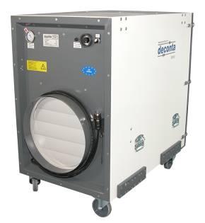
6 4.1 Use according to appropriateness 4 Technical description The negative pressure unit of the D-Series serves for the filtration of asbestos contaminated air, in temperature rage up +45 C, with external exhaust for the air. During asbestos sanitation works within closed rooms, you must avoid that asbestos fibres leave the sanitation area and in this way endanger humans and the environment. For this reasons, the sanitation areas (also called dirty area) have to be separated from the clean area with the help of a negative pressure unit and kept in dynamic negative pressure. An integrated filtering system establishes the conditions that the asbestos concentration in the exhausted air does not exceed max. 1000F/m³. The exhausted air is blown in the open air. The device is not appropriate for the filtration of flammable gas or dust. 4.2 Description of the device The negative pressure unit serves for the filtration of asbestos contaminated air via a 3- steps filter unit. (D 60 and D 60 E only 2-steps). The inserted Hepa filter complies with the requirements according to EN 1822 classification H13. By stacking of several devices, minor floor space is needed. Smooth and easy-to-decontaminate housing Stable and light housing 3-fold sealed hepa filter Hepa filter according to EN 1822 classification H13 Very low emission during the change of the filter. Filter change in 3 minutes The filter change is indicated visually via a pressure gauge (for the D 60 E via a signal lighting) Rustproof and powder coated housing continuously variable control 0-100% (SE and SRE) automatic soft starting, also after a power failure all operation and function elements are shock-protected stackable housing, ergo minor floor space Power optimised fan with high capacity Options: Attachment housing for the second hepa filter (Double filtration) Attachment housing for pocket filter Acoustical indication for the filter change Suction adapter Page 6

7 You can obtain the control of the negative pressure unit optionally in following models: D 60 E: ON / OFF D60 manual, continuously variable control SE D 100 ON /OFF manual, continuously variable control SE automatic control SRE D 305 ON /OFF Manual, continuously variable control SE Automatic control SRE D 610 ON /OFF Manual, continuously variable control SE Automatic control SRE D 910 Manual, continuously variable control SE Automatic control SRE D 1200 ON /OFF (only for 400 V / 32 A) Manual, continuously variable control SE Automatic control SRE 4.3 Control ON / OFF For the power regulation, the negative pressure unit is delivered in series with an ON/OFF switch. D 305 D 610 D 60 D 1200 Page 7
8 4.4 Control SE For the power regulation the negative pressure unit is delivered in series with a manual continuously variable control. 4.5 Control SRE For the power regulation the negative pressure unit is delivered in series with an electronic control, in order to measure and to regulate the negative pressure. The negative pressure is measured between the dirty area and at a reference point to be determined (adjoining rooms) and the set point is kept by the continuous speed regulation of the electric fan. On reaching the maximal fan capacity, a LED Fan will beam. The necessary filter change will be indicated by the LED Filter LED Filter LED Fan Page 8
9 4.6 Description of the filter / classification Integrated in the unit is a 3-step filtering combination (D 60 and D 60 E only 2-steps). In particular: Pre- and intermediate filter Pre-filter Intermediate filter Filter class according to DIN / EN 779 Frame G3 / EU3 Cardboard frame, 47 mm width G4 / EU4 Cardboard frame, 47 mm width Filter medium Fiber glass Synthetic Degree of separation (Am) 85 % 90 % Nominal rated current: 5400m³/h/m² 5400m³/h/m² Nominal velocity in blower stream at nominal volume 1,5 m/s 1,5 m/s Difference of initial pressure 30 Pa 42 Pa Recommended difference of final pressure 450 Pa 250 Pa Temperature / Air humidity Filter dimensions (in mm): D 60 E D 60 D 100 D 305 D 610 D 910 D C/100% RF (relative humidity) x 305 x x 610 x x 610 x x 910 x x 910 x C/100% RF (relative humidity) 305 x 305 x x 305 x x 305 x x 610 x x 610 x x 910 x x 910 x 47 Page 9
10 Hepa filter, suspended matter filter (S) Frame Plastic Filter medium Micro fiber glass paper Sealing mass Polyurethane Seals Filter surface D 60 E D 60 D 100 D 305 D 610 D 910 D 1200 Polyurethane 2 m² 2 m² 7 m² 15 m² 31 m² 48 m² 48 m² Filter classification H13 according to EN 1822 Degree of separation Temperature / Air humidity Filter dimensions (in mm): D 60 E D 60 D 100 D 305 D 610 D 910 D 1200 Protective grid >99,95%Most Penetraded Partikel Size 70 C/100% RF (relative humidity) 284 x 284 x x 284 x x 305 x x 610 x x 610 x x 910 x x 910 x 292 Grid, both sides Page 10
, the air capacity decreases.")
11 4.7 Information regarding the change of filter The frequency of the change of filter depends on the degree of pollution of the filter. If the sealing up of the filter increases (contamination of the filter), the air capacity decreases. For the control of the filter during the operation, the device is equipped with a manometer (for D 60 E a signal light). Important: Use only approved, faultless filter! From the following chart you can take for the change of the filter, the indications of values for the filter as-new condition and the indications of the recommended change of the filter. If the indication reaches the value for the recommended change of filter do please first change the preliminary and intermediate filter. If the indication falls at 100 Pascal (for D 60 at 50 Pascal) or more, the device can be operated further. If the value falls at lesser than 100 Pascal (for D 60 at 50 Pascal), you have to change the Hepa filter Device As-new condition Recommended filter change by D Pascal 470 Pascal D Pascal 750 Pascal D Pascal 950 Pascal D Pascal 1000 Pascal D Pascal 1100 Pascal D Pascal 900 Pascal Page 11

 in order to obtain a floor")


12 4.8 Piling of several devices The negative pressure units of the D-range can be pilled (except D 60 E) in order to obtain a floor space as small as possible. D 60 and D 100 are pilled thanks to an anti-skidding centering facility. D 305, D 610, D910 and D 1200 are connected thanks to a tight and solid screwed pilling system Pilling system Page 12
13 5 Technical data 5.1 Fan characteristic curve D 60 E and D stat. Pressure boosting PA => Volume flow V m³/h => Technical data: Voltage: 230 V Frequency: 50 Hz Speed: 2890 U/min Air discharge: 980 m³/h free exhausting max. discharge temperature: 45 C Page 13
14 5.2 Fan charasteristic curve D 100 stat. Pressure boosting PA => Volume flow V m³/h => Technical data: Voltage: 230 V Frequency: 50 Hz Speed: 2850 U/min Air discharge: 1200 m³/h free exhausting max. discharge temperature: 45 C Page 14
15 5.3 Fan characteristic curve D 305 stat. Pressure boosting PA => Volume flow V m³/h => Technical data: Voltage: 230 V Frequency: 50 Hz Speed: 2850 U/min Air discharge: 2400 m³/h free exhaust max. discharge temperature: 45 C Page 15
16 5.4 Fan characteristic curve D 610 stat. Pressure boosting PA => Volume flow in m³/h => Technical data: Voltage: 230 V Frequency: 50 Hz Speed: 2800 U/min Air discharge: 6000 m³/h free exhausting max. discharge temperature: 45 C Page 16
17 5.5 Fan characteristic curve D 910 stat. Pressure boosting PA => Volume flow in m³/h => Technical data: Voltage: 230 V Frequency: 50 Hz Speed: 2780 U/min Air discharge: 7500 m³/h free exhausting max. discharge temperature: 45 C Page 17
18 5.6 Fan characteristic curve D stat. Pressure boosting PA => Volume flow in m³/h => Technical data: Voltage: 400 V Frequency: 50 Hz Speed: 2900 U/min Air discharge: m³/h free exhausting max. discharge temperature: 45 C Page 18
19 5.7 Power data D 60 E D 60 D100 D305 D 610 D 910 D 1200 Air power free blowing in m³/h Air power with filter in m³/h Power connection in Volt Current consumption in Ampere Engine power in kw ,17 0,55 1, ,5 Filter system 2-steps 3-steps Pre-filter EU 3 Intermediate filter EU 4 Hepa filter According to EN 1822 classification H Connections, dimensions, weights Hose connection exhaust Hose connection Suction D 60 E D 60 D100 D305 D 610 D optional 4x 100 or 1x 150 optional 1x optional Fan unit D 1200 Filter unit FG x optional 2x 450 2x 450 optional 2x 450 Length in mm Width in mm Height in mm Weight incl. filter in kg 21 19, (no FG 5) 70 Page 19
20 5.9 Power loss in hose lines Following factors have adverse influence: Hose lines too long Bends and bows in the hose lines Cross-section narrowing of the hose lines Resistance diagram for hose lines Hose line with external spiral Sleeky inside in 10 mtr. Length Page 20
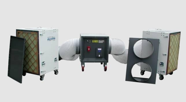
21 6 Assembly instructions The negative pressure unit is delivered ex-works and ready for immediate operation. If there are visible damages, do not operate the device. Please contact the deconta GmbH at once. 6.1 Assembly instructions with the example of D 610 (the procedure for D 60, D 100, D 305 and D 910 is identical) Please respect: Basically the negative pressure units D 60, D 100, D 305, D 610 and D 910 can also be operated directly in the dirty area (over pressure technique prevent the infiltration of the surrounding contaminated air in the housing). Because the devices are contaminated from outside and therefore need an expensive cleaning after the end of the sanitation work, one should avoid the use in the dirty area by all means. Connect the device with the wall between clean / and sanitation area Place it about. 100 mm in the sanitation area Seal the device with the wall Conduct the exhausted air hose in the open air Provide for enough supply air in the sanitation area Clean area Contaminated area Supply air opening with self-closing flaps Page 21

 of the ventilator unit by unscrewing the wing bolt Remove suction flange fixed to the filter housing for the transport")
 on the filter unit in order not to loose them Connect the filter units and ventilator unit with the hoses Conduct the")
22 6.2 Assembly with the example of D 1200 Exit flange Transport lid 2 Transport lid 2 Transport lid 1 Exit flange Place the filter unit at approximately 100 mm in sanitation area and fix it Seal the filter unit with the wall Remove the transport lid (Pos.2) of the ventilator unit by unscrewing the wing bolt Remove suction flange fixed to the filter housing for the transport and fix them by means of 4 wing nuts to the ventilator unit Screw the transport lids (Pos. 2) on the filter unit in order not to loose them Connect the filter units and ventilator unit with the hoses Conduct the supply air hose in the open air Care for enough supply air in the sanitation area Remove the transport lid (Pos.1) of the filter unit Page 22
23 Clean area Sanitation area Exhaust hose Attention: Connect the filter housings according to the draft with the ventilation unit and let rise up about 100mm in the sanitation area Page 23
, additional activated carbon filter or pocket filter")


24 6.3 Assembly of the optional attachment housing (SNAP) following the example of D 610 Optionally for a second hepa filter (Double filtration), additional activated carbon filter or pocket filter Dismount the prefilter and unscrew the security corners (if existing) Safety corners Place the attachment housing and fix the tension locks Tension lock Insert the Hepa filter / activated carbon filter Fix the tension frame by means of screws Insert the pre-filter By using an activated carbon filter, this should be inserted in the negative pressure unit and the hepa-filter in the attachment housing. Page 24
25 7.1 Control ON / OFF Instruction manual 7 Initial operation The negative pressure unit D 610 is delivered in series with an ON / OFF switch. Connect with the current Switch the ON / OFF switch Negative pressurisation Adjust the wished negative pressure at the supply air opening Negative pressure too high: Negative pressure too low: open the supply air opening shut the supply air opening 7.2 Control SE For the power regulation, the negative pressure unit is delivered in series with a manual continuous variable control. Connect with the current Operate the adjuster Maintenance of the negative pressure in the room Adjust the wished negative pressure at the supply air opening or the continuous variable adjuster Negative pressure too high: device Negative pressure too low: device open the supply air opening or decrease the shut the supply air opening or increase the Page 25
26 7.3 Control SRE For the power regulation the negative pressure unit is delivered in series with an electronic control, in order to measure and to regulate the negative pressure. The negative pressure is measured between the dirty area and at a reference point to be determined. In order to secure the adjusted values, the control is locked. A LED Fan will beam on reaching the maximal fan capacity, A LED Filter will beam if it is necessary to change the filter Control panel: LED Filter LED Fan Indication 1 Indication 2 Key ON/OFF Key AUTO/MANU Key + Key - Page 26
 and connect the PEtube 8 x 1 to the connection atmosphere Connection Atmosphere connection negative pressure The device is now ready for use.")
27 Starting position: Connect to the current Chose a measuring point in the dirty area and connect the PE-tube 8 x 1 to the negative pressure connection Chose the measuring point in the clean area (adjoining room) and connect the PEtube 8 x 1 to the connection atmosphere Connection Atmosphere connection negative pressure The device is now ready for use. The last memorized negative pressure value will be adjusted automatically. In order to change this value, you may procede as follow: Activate the key ON/OFF Chose the operation mode key AUTO/MANU Automatic - operation The reference value in automatic operation is set with the keys - and + in Steps of one Pascal (reference value in the display Thank2). Thanks to the speed control of the ventilator, the negative pressure is regulated at once automatically. In the display 1 you can see the actual negative pressure. Page 27
28 Manual - operation Instruction manual In manual operation the power of the ventilator is given with the keys - and + in maximum 7 steps. The display 2 represents this value in % In the display 1 you can see which negative pressure is created with the adjusted power. Important: Im Manual operation, the device does not regulate! 8.1 Maintenace 8 Maintenance The ventilator plants (deduster, industrial vaccum cleaners and devices for the deaeration or kipping in negative pressure) have to be overhauled or controlled once a year at least or if necessary by an expert. 8.2 Filter control During the operation the filter state has to be controlled as described under 4.7. Page 28
29 8.3 Change of filter Attention: Contaminated filters have to be changed under all corresponding safety measures Filter change only with a machine switched off Use approved filters only Do not use bonding agents on the machine Remove the hepa-filter: Remove the prefilter Unscrew the hexagone screws M8 and remove the tension frame Remove the hepafilter and dispose of it professionally Insertion of the hepa-filter: Control the sealing face of the machine and clean. Clean the inside of the housingi Insert the new filter in the middle Tighten the tension frame and the hexagone screws M8 (tighten the screws carefully) Insert the pre-filter Important: Treat the hepafilter with care because otherwise damages can suspend the effectivity of the filtration. Page 29
30 9 Possible failures and their repairs Failure Possible reason Repair Negative pressure too low Pre- / intermediate filters dirty Change the filters as described under 8.3 Device does not work Current source not correct Have power source examined and repaired by an expert. Device does not work Parts of the negative pressure unit defective Have the device repaired by deconta or an accredited workshop. Page 30
31 10.1 Circuit diagram D 60 E Instruction manual 10 Circuit diagrams Page 31
32 10.2 Circuit diagram D 60 SE Page 32
33 10.3 Circuit diagram D 100 ON / OFF Page 33
34 10.4 Circuit diagram D 100 SE Page 34
35 10.5 Circuit diagram D 100 SRE Page 35
36 10.6 Circuit diagram D 305 ON / OFF Page 36
37 10.7 Circuit diagram D 305 SE Page 37
38 10.8 Circuit diagram D 305 SRE Page 38
39 10.9 Circuit diagram D 610 ON / OFF Page 39
40 10.10 Circuit diagram D 610 SE Page 40
41 10.11 Circuit diagram D 610 SRE Page 41
42 10.12 Circuit diagram D 910 SE Page 42
43 10.13 Circuit diagram D 910 SRE Page 43
44 10.14 Circuit diagram D 1200 SE Page 44
45 10.15 Circuit diagram D 1200 SRE Page 45
46 11 Sound level measuring Status: Engine power 100%, outside Value in db (A) Device A1 A2 A3 A4 A5 B1 B2 B3 B4 B5 C1 C2 C3 C4 C5 D1 D2 D3 D4 D5 D 60 E D D D D D D The setting of a silencer reduces the sound level in due consideration of a loss of power. Page 46
47 12 Declaration of conformity deconta GmbH Im Geer 20 D Isselburg EU Declaration of Conformity Product: Negative pressure unit Type: 411, 414, 415, 430, 431, 432, 450, 451,453, 454, 455, 456, 457, 458, 490, 491, 601, 620 The design of the units corresponds to the following regulations: EU- Machine directive 98/37/EG EU- low-voltage directive 2006/95/EG Applied harmonised standards: EN Applied national standards: DIN VDE 0701, DIN VDE 0702 W. Weßling Isselburg, The copyright of this instruction manual remains with deconta. This manual is intended for assembly, operation and maintenance personnel. It contains instructions and drafts of technical nature which may neither be distributed nor used in any unauthorised way for competitive purposes or passed on to others. For more information, please see our website Page 47
30T A/Manual Hydraulic Shop Press
 30T A/Manual Hydraulic Shop Press Operation Manual 1 1. Important Information 1.1 Safety Information 1.1.1 Hazard Symbols Used in the Manuals This manual includes the hazard symbols defined below when
Instruction Manual Contact Pressure Vacuum Gauge
 MS10 Instruction Manual Contact Pressure Vacuum Gauge Table of Contents 1. Safety Instructions 2. Intended Applications 3. Product Description and Functions 4. Installation 5. Commissioning 6. Maintenance
Type BBS-03, BBS-05, BBS-06, BBS-25
 Type BBS-03, BBS-05, BBS-06, BBS-25 Sterile connection elements Sterile Verbindungselemente Raccords union stériles Operating Instructions Bedienungsanleitung Manuel d utilisation 1. THE OPERATING INSTRUCTIONS
Vertex VP Operation and Maintenance
 AIRBENCH LTD Vertex VP Operation and Maintenance This Edition: 2 October 2018 AirBench Ltd, 14 Grange Farm Road, Colchester CO2 8JW www.airbench.com +44 (0) 1206 791191 Copyright AirBench Ltd 2016 Page
Squeegee Unit for MRS Multi-Recovery System
 En Operating Instructions Squeegee Unit for MRS Multi-Recovery System Translation of the original operating instructions Squeegee - MRS Table of Contents Safety Recommendations Technical Data - MRS Booth
KTM OM-2 SPLIT BODY FLOATING BALL VALVES INSTALLATION AND MAINTENANCE INSTRUCTIONS
 Before installation these instructions must be fully read and understood SECTION 1 - STORAGE 1.1 Preparation and preservation for storage All valves should be properly packed in order to protect the parts
Mounting and Operating Instructions EB 2558 EN. Self-operated Pressure Regulators. Type Pressure Build-up Regulator
 Self-operated Pressure Regulators Type 2357-31 Pressure Build-up Regulator with safety function and integrated excess pressure valve Type 2357-31 with non-return unit at port C Ports A and B with soldering
Operating and maintenance manual Filter and reducing station Series / 1.0
 Operating and maintenance manual Filter and reducing station Series 961 04.2017 / 1.0 Original instructions ARCA Regler GmbH. All rights reserved. Cover picture background: Freepik.com ARCA Regler GmbH
Safety. Operating instructions Solenoid valve for gas VG 6 VG 15/10 DANGER. Contents WARNING CAUTION. Changes to edition 09.14
 15 Elster GmbH Edition 7.15 Translation from the German 519 D F NL I E DK S N P GR TR CZ PL RUS H www.docuthek.com Operating instructions Solenoid valve for gas VG VG 15/1 Contents Solenoid valve for gas
Mobile High Pressure Compressor Unit for Compressing Air and Breathing Air. PE 250-TE with compressor control (optional equipment)
") Mobile High Pressure Compressor Unit for Compressing Air and Breathing Air Types: PE 200-TE PE 250-TE PE 300-TE Production status: F02 PE 250-TE with compressor control (optional equipment) General Medium
Mobile High Pressure Compressor Unit for Compressing Air and Breathing Air Types: PE 200-TE PE 250-TE PE 300-TE Production status: F02 PE 250-TE with compressor control (optional equipment) General Medium
Operating instructions
 Operating instructions Type TEKA Airtech P18/P24/P30 TEKA Absaug- und Entsorgungstechnologie GmbH Industriestraße 13 D-46342 Velen Postfach 1137 D-46334 Velen Tel.: +49 (0) 2863 9282-0 Fax: +49 (0) 2863
Operating Manual VSA100A. tina29e1 ( )
") Operating Manual Incl. EU Declaration of Conformity Vacuum Switch VSA100A tina29e1 (2017-05) 1 Product Identification In all communications with INFICON, please specify the information on the product nameplate.
Operating Manual Incl. EU Declaration of Conformity Vacuum Switch VSA100A tina29e1 (2017-05) 1 Product Identification In all communications with INFICON, please specify the information on the product nameplate.
SPECIFICATIONS Type: Twin stack, single phase Tank: 4 gallon Air Output: PSI; PSI Max PSI: 125 PSI HP: 1.
 2 GALLON TWIN STACK AIR COMPRESSOR Model: 9526 DO NOT RETURN TO STORE. Please CALL 800-348-5004 for parts and service. CALIFORNIA PROPOSITION 65 WARNING: You can create dust when you cut, sand, drill or
Pre-filter for Brushless Blower Instruction Manual
 Pre-filter for Brushless Blower 781-70-702 Instruction Manual Minebea Co., Ltd. Industrial Machinery Business Unit 251-8531 1-1-1 Katase,Fujisawa,kanagawa Contact Us Industrial Machinery Product Sales
PRAHER PLC-MP AQUASTAR MANAUL 2009
 PRAHER PLC-MP AQUASTAR MANAUL 2009 1. Copyrights This Operating Manual contains copyright-protected information. All rights reserved to Praher Kunststofftechnik GmbH. This Operating Manual is designed
Declaration of Conformity as per Directive 97/23/EC
 Declaration of Conformity as per Directive 97/23/EC The manufacturer declares that:, 47906 Kempen, Germany Continuous, inline sampling valves Series 27f, with packing Operate with either; Star lever, or
Operating instructions
 Operating instructions TEKA Airtech P10 TEKA Absaug- und Entsorgungstechnologie GmbH Industriestraße 13 D-46342 Velen Postfach 1137 D-46334 Velen Tel.: +49 (0) 2863 9282-0 Fax: +49 (0) 2863 9282-72 E-Mail:
Neotecha SAPRO - Aseptic sampling valve SV Installation, operation and maintenance instructions
 Before installation these instructions must be fully read and understood 2 Safety Please read these instructions carefully. 2.1 General danger potential Not paying attention to this instruction Incautious
Installation and operating manual. Pneumatic control station LK product no: PCS 1-10
 LK product no: PCS 1-10 Article no: 74503 Revision:8 Article no: 74503 Revision: 8 2 (23) Contents 1. General information... 5 2. Safety precautions... 5 2.1 Significance of symbols... 5 2.2 Explanatory
2 GALLON TWIN STACK AIR COMPRESSOR W/ HOSE REEL
 2 GALLON TWIN STACK AIR COMPRESSOR W/ HOSE REEL Model: 52024 CALIFORNIA PROPOSITION 65 WARNING: You can create dust when you cut, sand, drill or grind materials such as wood, paint, metal, concrete, cement,
Overspeed governors (113 OG Моment 250 MR, 114 OG Moment 250 A3, 115 OG Moment 250 MRL, 119 OG Moment 250 MRL/1)
") Overspeed governors (113 OG Моment 250 MR, 114 OG Moment 250 A3, 115 OG Moment 250 MRL, 119 OG Moment 250 MRL/1) Instructions for installation and operation 113 OG Моment 250 MR 115 OG Moment 250 MRL Overspeed
Overspeed governors (113 OG Моment 250 MR, 114 OG Moment 250 A3, 115 OG Moment 250 MRL, 119 OG Moment 250 MRL/1) Instructions for installation and operation 113 OG Моment 250 MR 115 OG Moment 250 MRL Overspeed
Declaration of Conformity as per Directive 97/23/EC
 Declaration of Conformity as per Directive 97/23/EC The manufacturer declares that:, 47906 Kempen, Germany Multi-way diverting valves Series 29a and Series 29b, with packing with lever 1. The valves are
A17W49_MASEM_F_EN MANUAL
 AW9_MASEM_F_EN MANUAL CONTENTS Identification. Manufacturer. Product name. Year of manufacture. Area of use. Declaration of conformity Technical specification. Design. Function. Technical data. Electrical
Type 0404 / /2-way solenoid valve 2/2-Wege-Magnetventil Électrovanne 2/2 voies Operating Instructions Bedienungsanleitung Manuel d utilisation
 Type 0404 / 5404 2/2-way solenoid valve 2/2-Wege-Magnetventil Électrovanne 2/2 voies Operating Instructions Bedienungsanleitung Manuel d utilisation 1 OPERATING INSTRUCTIONS The operating instructions
Solenoid gas valve. The solenoid gas valve is also applicable as a main gas valve Pilot gas valve for forced draft burners
 7 634 VGS1... with AGA67 connector VGS2... with AGA67 connector Solenoid gas valve VGS The solenoid gas valve is also applicable as a main gas valve Pilot gas valve for forced draft burners The VGS and
Instruction Manual Otoflash G171 UV-flash-device for Light Curing
 Instruction Manual Otoflash G171 UV-flash-device for Light Curing Index 1) General Information 2) Initial Operation of Device 3) Important Notes 4) Use with timer 5) Exchanging the flash module 6) Maintenance,
Pressure Reducing Valve DMV 750 set range: bar
 Pressure Reducing Valve DMV 750 set range:.0-6.0 bar Advantage pressure setting possible at any time, also during operation hermetically sealed by valve diaphragm high level of operating safety and long
VACUUM REGULATORS CONTENTS
 CAD drawing data catalog is available. ACCESSORIES GENERAL CATALOG AIR TREATMENT, AUXILIARY, VACUUM, AND FLUORORESIN PRODUCTS CONTENTS Small Regulators Features 759 Specifications, Order Codes, Flow Rate
DK46 - DK800 Supplementary instructions
 DK46 - DK800 Supplementary instructions Variable area flowmeter Device category II2G with electrical internals Additional Ex manual KROHNE CONTENTS DK46 - DK800 1 Safety instructions 3 1.1 General... 3
Operating Instructions
 Operating Instructions Light-metal Ex d enclosures / flameproof enclosure > 8265/0 Empty enclosure > 8265/4 Control panel, integrated in Ex e enclosure > 8265/5 Control panel Table of Contents 1 Table
Measurement accessories METPOINT OCV for the measurement in systems up to 40 bar
 EN - english Instructions for installation and operation Measurement accessories METPOINT OCV for the measurement in systems up to 40 bar Dear customer, Thank you for deciding in favour of the METPOINT
97C COMPRESSOR KIT 12V PART NO C COMPRESSOR KIT 24V PART NO C COMPRESSOR KIT PART NO
 97C COMPRESSOR KIT 12V PART NO. 00097 97C COMPRESSOR KIT 24V PART NO. 02497 98C COMPRESSOR KIT PART NO. 00098 97C 98C IMPORTANT: It is essential that you and any other operator of this product read and
24L OIL FREE AIR COMPRESSOR MODEL NO: TIGER 7/250 PART NO: OPERATION & MAINTENANCE INSTRUCTIONS LS10/13
 24L OIL FREE AIR COMPRESSOR MODEL NO: TIGER 7/250 PART NO: 2244030 OPERATION & MAINTENANCE INSTRUCTIONS LS10/13 INTRODUCTION Thank you for purchasing this product. Before attempting to use this product,
Diaphragm Pressure Keeping Valve
 Product: Diaphragm pressure keeping valve Type: 620.D 622.D 623.D 624.D 625.D 626.D 627.D Please state here the exact type and serial number of your diaphragm pressure keeping valve. (can be read off the
Mounting instructions. Strain transducer SLB-700A. B 26.SLB700A.10 e
 Mounting instructions Strain transducer SLB-700A B 26.SLB700A.10 e SLB700A 3 Contents Page Safety instructions.............................................. 4 1 Applications..................................................
Pfeiffer. Operating, assembly and maintenance instructions for discontinuous sampling valve Series 27i. 1. Design, operation and dimensions
 Operating, assembly and maintenance instructions for discontinuous sampling valve Series 27i This equipment may only be dismounted and disassembled by skilled staff, who are familiar with the assembly,
* * Data Sheet and Operating Manual. Digital manometer ME01 ## # 87 # HL S#### Dust explosion protection Zone 22.
 *09005087* DB_BA_EN_ME01_S Rev.A 12/16 *09005087* d e v e l o p i n g s o l u t i o n s Data Sheet and Operating Manual ME01 Digital manometer Table of Contents ME01 ## # 87 # HL S#### Dust explosion protection
Installation and Maintenance Manual. ECO Filtration Unit with 6-way-Top-Mount-Valve. Art. Nr
 Installation and Maintenance Manual ECO Filtration Unit with 6-way-Top-Mount-Valve Art. Nr. 300100 300101 300102 Important Details: - Using of this filtration unit for swimming pools and its guard band
LTB013EN. Operating Instruction Trimod Besta Level Switch types XA 5, XB 5 for use in potentially explosive atmospheres acc.
 LTB013EN Operating Instruction Trimod Besta Level Switch types XA 5, XB 5 for use in potentially explosive atmospheres acc. to IECEx scheme Subject to technical modification Bachofen AG Ackerstrasse 42
Declaration of Conformity as per Directive 97/23/EC
 Declaration of Conformity as per Directive 97/23/EC The manufacturer declares that:, 47906 Kempen, Germany Discontinous, inline sampling valves Series 27a and Series 27g, with packing with lever (180 )
Product Manual B-Safety ClassicLine & PremiumLine Emergency Eyewash and Eye/Face Wash Equipment
 Product Manual B-Safety ClassicLine & PremiumLine Emergency Eyewash and Eye/Face Wash Equipment 1. Application Emergency eyewash and eye/face wash equipment are prescribed first aid installations for workplaces
Safety Powder Spray Systems
 Instruction Sheet P/N 107 952C Safety Powder Spray Systems 1. Introduction This section contains general safety instructions for using your Nordson equipment. Task- and equipment-specific warnings are
Innovative Vacuum for Automation. Operating Instructions Dust Filter STF P / STF-D P.
 Innovative Vacuum for Automation EN Operating Instructions Dust Filter STF P / STF-D P 30.30.01.00059/02 11.2014 www.schmalz.com Note These operating instructions were written in the German language. This
User Manual. Quantos Automated Dosing Liquid Module
 User Manual Liquid Module 1 Safety Information 1.1 Definition of warnings and symbols Signal Words WARNING for a hazardous situation with medium risk, possibly resulting in severe injuries or death if
MANUAL DIRECT PURGE OPTION. UNION Instruments GmbH CWD2005 PLUS. General information, safety standards and regulations for direct purge option
 MANUAL DIRECT PURGE OPTION UNION Instruments GmbH CWD2005 PLUS General information, safety standards and regulations for direct purge option Version: V1.00 Stand: 24.03.2010 Union Instruments GmbH Zeppelinstr.
MANUAL. Sesame. Thermoplastic Tank Technologies
 MANUAL Sesame Thermoplastic Tank Technologies INSTALLATION AND USER GUIDE CONTENT 1. GENERAL 3 2. IMPORTANT 3 3. INSTALLATION EXPANSION VESSEL 4 4. USE EXPANSION VESSEL 5 5. AIR CELL REPLACEMENT 5 5.1
AIR COMPRESSOR OPERATING INSTRUCTION AND PARTS LIST
 AIR COMPRESSOR OPERATING INSTRUCTION AND PARTS LIST OIL-LESS TYPE IMPORTANT: PLEASE READ CAREFULLY BEFORE STARTING OPERATIONS. THE CONTENTS ARE FOR GENERAL INFORMATION OF ALL THE SIMILAR MODELS. Record
24L AIR COMPRESSOR MODEL NO: TIGER 11/250 PART NO: OPERATION & MAINTENANCE INSTRUCTIONS LS01/13
 24L AIR COMPRESSOR MODEL NO: TIGER 11/250 PART NO: 2244010 OPERATION & MAINTENANCE INSTRUCTIONS LS01/13 INTRODUCTION Thank you for purchasing this product. Before attempting to use this product, please
Code AWC20HP Air Compressor
 Code 951816 AWC20HP Air Compressor Index of Contents Index of Contents 02 Declaration of Conformity 02 What s Included 03 Safety Precautions 03 Specifications (AWC20HP Air Compressor) 04 Assembly Instructions
INSTRUCTION MANUAL MST AFTERCOOLER SYSTEM MODEL
 INSTRUCTION MANUAL MST AFTERCOOLER SYSTEM MODEL 8059601 To be used with MST Model 8050501 Ambient Air Pump 7/12/05 2 TABLE OF CONTENTS GENERAL INFORMATION... 3 WARNING...4,5 UNPACKING AND AFTERCOOLER ASSEMBLY
Product instruction manual Easymount Sign Laminators EM-S1400C, EM-S1600C, EM-S1400H, EM-S1600H
 Product instruction manual Easymount Sign Laminators EM-S1400C, EM-S1600C, EM-S1400H, EM-S1600H The Easymount Sign has been designed to be user friendly, however we strongly recommend you take a few minutes
BMR 2100XL Operating Instructions Page 1 of 13
 BMR 2100XL Operating Instructions Page 1 of 13 Thank you for deciding to purchase a Swisswing BMR 2100XL (Biomechanical Stimulation Device will be referred to in these operating instructions as the BMR).
Holugt Portable Unit HL120 Electric
 Holugt Portable Unit HL120 Electric SPECIFICATIONS Capacity (litre per minute) 100 Maximum pressure (bar) 330 Working pressure (bar) 200 or 300 Dimensions (cm) 65x35x39 Weight (kg) 39.5 Sound Level (db)
TEST BENCH SAFETY VALVES ¼ - 5 DN10 DN125
 TEST BENCH SAFETY VALVES ¼ - 5 DN10 DN125 Model: VC-40-VYC Table of contents 1. - Installing the test bench 1.1.1- Connecting the compressed air / nitrogen source 1.1.2- Maximum test pressure according
400H HARDMOUNT AIR COMPRESSOR KIT PART NO H HARDMOUNT AIR COMPRESSOR KIT PART NO
 400H HARDMOUNT AIR COMPRESSOR KIT PART NO. 40042 450H HARDMOUNT AIR COMPRESSOR KIT PART NO. 45042 400H 450H IMPORTANT: It is essential that you and any other operator of this product read and understand
20 Ton SD Shop Press Operating Instructions
 20 Ton SD Shop Press Operating Instructions MODEL NO. 850SD Hazard Symbols Used in the Manuals This manual includes the hazard symbols defined below when the operations or maintenance job involves a potential
GENO -Flushing Compressor Product Data Sheet F 02
 GENO -flushing compressor 1988 K Fig. 1: GENO -flushing compressor 1988 K Designated application is suitable for the following fields of application: Flushing of pipes with water/air mix prior to the start-up
SF SERIES CNG COMPRESSOR MODEL HF-4MH. 4 Nm3/Hour Displacement OPERATION MANUAL
 SF SERIES CNG COMPRESSOR MODEL HF-4MH 4 Nm3/Hour Displacement OPERATION MANUAL 1 Content 1. General Description...3 2. Main technical parameters...3 3. Structural principle...4 3.1Main structure...4 3.2Compressor
Declaration of Conformity as per Directive 97/23/EC and Manufacturer s Declaration as per Directive 98/37/EC
 Declaration of Conformity as per Directive 97/23/EC and Manufacturer s Declaration as per Directive 98/37/EC The manufacturer declares that:, 47906 Kempen, Germany Continuous, PFA-lined, inline sampling
LK-SX CO 2 +VOC. Application. Security Advice Caution. Notes on Disposal
 LK-SX CO 2 +VOC Sensor for detection of carbon dioxide (CO 2) and mixed gas content in air ducts Data sheet Subject to technical alteration Issue date: 24.08.2015 Application For detection of CO2 and VOC.
Combination Air Valve
 Combination Air Valve For Sewage and Wastewater Model C50 Installation, Operation and Maintenance Manual (IOM) Table of Contents General... Page 2 Safety... Page 2 Operational Data... Page 3 Materials
VERTICAL AIR COMPRESSORS
 VERTICAL AIR COMPRESSORS MODEL NO: VE11C150, VE15C150, VE18C150 PART NO: 2226005, 2226000, 2226015 OPERATION & MAINTENANCE INSTRUCTIONS LS0615 INTRODUCTION Thank you for purchasing this CLARKE Vertical
JET SWIM ELEGANCE 70 INSTALLATION AND USER GUIDE
 JET SWIM ELEGANCE 70 INSTALLATION AND USER GUIDE i Read the instructions 1. Installation mounting By purchaising the ELEGANCE device, you obtained a high-quality product that will help you to enjoy the
200 PSI COMPRESSORS - MODEL NUMBERS
 200 PSI COMPRESSORS - MODEL NUMBERS 380C AIR COMPRESSOR KIT PART NO. 38033 480C AIR COMPRESSOR KIT PART NO. 48043 380C 480C IMPORTANT: It is essential that you and any other operator of this product read
2-1- Shipping Receiving Lifting Location on Site Installation Stages 6
 NEUTRAL GROUNDING RESISTORS INSTALLATION, OPERATION & MAINTENANCE MANUAL Contents 1- SAFETY INSTRUCTIONS... 3 1-1- Compliance with Instructions in this Manual. 3 1-2- Guidance Notes Installation.... 3
Inoxair. Repair Manual. Content. Edition: 12/2010. Subject to technical changes for reasons of the continous development.
 Inoxair Repair Manual Edition: 12/2010 Content 1) Serial number 2) Technical data 3) Functional principle 4) Problem analysis 5) Removal 6) Repairs 7) Circuit diagram and cable-connection-plan 8) Pneumatic
100C Air Compressor Kit
 10010 100C Air Compressor (standard mounting bracket, CE Spec) 10014 100C Air Compressor (no leader hose or check valve, CE Spec) 10016 100C Air Compressor (with Omega Bracket, CE Spec) IMPORTANT: It is
Installation, Operating & Maintenance Instructions. Variable leak valve with manual actuator. Series 590 DN 16 mm (I. D. ⅝") E
 E") Installation, Operating & Maintenance Instructions Variable leak valve with manual actuator DN 16 mm (I. D. ⅝") This manual is valid for the following product ordering numbers: 59024-. E01 -... Sample
Installation, Operating & Maintenance Instructions Variable leak valve with manual actuator DN 16 mm (I. D. ⅝") This manual is valid for the following product ordering numbers: 59024-. E01 -... Sample
OPERATING MANUAL. Contents. Bottom outlet ball valve Type ecoline
 OPERATING MANUAL Bottom outlet ball valve Type ecoline Contents 1 General Information 2 Safety 3 Packing, Handling, Storing 4 Product description 5 Preparation, Assembly 6 Commissioning 7 Handling 8 Attendance
AIR COMPRESSOR MANUAL INSTALLATION, OPERATION AND MAINTENANCE GUIDE
 AIR COMPRESSOR MANUAL INSTALLATION, OPERATION AND MAINTENANCE GUIDE 1. DESCRIPTION The compressor is a reciprocating air pump mounted on and driven by an electric induction motor. Mounted on a sturdy frame
VS18/26 with PROFINET and EtherNet/IP Interface. ATEX Installation Instructions
 VS18/26 with PROFINET and EtherNet/IP Interface ATEX Installation Instructions INDEX 1. INTENDED USAGE 3 2. OPERATING MANUAL ATEX 4 2.1 General conditions 4 2.2 Installation 5 2.3 Operating 5 2.4 Failures
Instructions for Installation, Use and Maintenance FSI Safety Tank Shower Systems
 Instructions for Installation, Use and Maintenance FSI Safety Tank Shower Systems per DIN 12 899 T1-3 and ANSI Z 358-2004 Table of Contents for Instructions for Use Section 1 Manufacturer, Safety Shower
42045 Heavy Duty ADA Base Model Kit: 85/105 PSI (ADA Compressor Only) Heavy Duty ADA Base Model Kit: 110/145 PSI (ADA Compressor Only)
 Heavy Duty ADA Base Model Kit: 110/145 PSI (ADA Compressor Only)") 42045 Heavy Duty ADA Base Model Kit: 85/105 PSI (ADA Compressor Only) 42047 Heavy Duty ADA Base Model Kit: 110/145 PSI (ADA Compressor Only) 45052 Constant Duty ADA Base Model Kit: 85/105 PSI (ADA Compressor
42045 Heavy Duty ADA Base Model Kit: 85/105 PSI (ADA Compressor Only) 42047 Heavy Duty ADA Base Model Kit: 110/145 PSI (ADA Compressor Only) 45052 Constant Duty ADA Base Model Kit: 85/105 PSI (ADA Compressor
New AQF Filter Polymer Filtration System
 New AQF Filter Polymer Filtration System Operator Manual Covering Serial Number 20002001 onwards February 2011 Index Disclaimer notice...3 Introduction...4 Important safety notices...5 Getting started...6
USER MANUAL. JET TST and JET TST S.
 USER MANUAL JET TST and JET TST S www.sisteven.com Types of Jet fans: JET TST UNI: Impulse axial fan single direction JET TST S UNI: Impulse axial fan single direction (short case) JET TST REV: Impulse
Workshop Compressors CLASSIC Series
 www.kaeser.com Workshop Compressors CLASSIC Series Displacement: 210 to 40 l/min Pressure: 10 bar What do you expect from your Classic workshop compressor? Quality results can be achieved only by using
3 GALLON, OILLESS PANCAKE COMPRESSOR INSTRUCTIONS. Item #31289
 3 GALLON, OILLESS PANCAKE COMPRESSOR INSTRUCTIONS Item #31289 The EASTWOOD 3 GALLON, OILLESS PANCAKE COMPRESSOR, with an Integral Air Regulator, efficiently supplies all compressed air requirements for
Flowmeter. Original operating manual DFM
 Flowmeter Original operating manual Series DFM 165 350 Version BA-2016.08.09 EN Print-No. 300 458 TR MA DE Rev002 ASV Stübbe GmbH & Co. KG Hollwieser Straße 5 32602 Vlotho Germany Phone: +49 (0) 5733-799-0
100L AIR COMPRESSOR MODEL NO: TIGER 16/1010 PART NO: OPERATION & MAINTENANCE INSTRUCTIONS LS01/13
 100L AIR COMPRESSOR MODEL NO: TIGER 16/1010 PART NO: 2244025 OPERATION & MAINTENANCE INSTRUCTIONS LS01/13 INTRODUCTION Thank you for purchasing this product. Before attempting to use this product, please
OPERATION MANUAL PNEUMATIC VALVES
 OPERATION MANUAL PNEUMATIC VALVES DIRECTIVE 2014/34/EU ATEX ENGLISH Index 1 Product identification 2 Security 3 Guarantee 4 Transportation 5 Assemblage 6 Setting up 7 Adjustments 8 Technical information
BOSS PULISCI PROVA IMPIANTI MEDIA
 BOSS PULISCI PROVA IMPIANTI MEDIA Pump for power flushing operations and removal of impurities, suitable for hydraulic, solar, floor systems and for cooling circuits of medium size. Suitable for buildings,
444C DUAL PERFORMANCE VALUE PACK
 (Chrome) PART NO. 44432 IMPORTANT: It is essential that you and any other operator of this product read and understand the contents of this manual before installing and using this product. SAVE THIS MANUAL
HS653 Negative Pressure Ventilation Controller
 HS653 Negative Pressure Ventilation Controller General Installation Notes: Make sure that power is disconnected from system prior to servicing. Installation of this equipment and related OEM equipment
VERTICAL AIR COMPRESSORS
 VERTICAL AIR COMPRESSORS MODEL NO: VE15C150, VE18C150, VE25C150 PART NO: 2226010, 2226020, 2226025 OPERATION & MAINTENANCE INSTRUCTIONS LS0715 INTRODUCTION Thank you for purchasing this CLARKE Vertical
LK-SX VOC. Application. Security Advice Caution. Notes on Disposal. Combined sensor mixed gas. Data sheet
 LK-SX VOC Combined sensor mixed gas Data sheet Subject to technical alteration Issue date: 24.08.2015 Application The sensor detects air quality in ventilation ducts. A stronger output signal of the sensor
erc-o 2 -tech Ò innovative gas systems Markwerbener Str Weißenfels Germany
 Compart Umwelttechnik GmbH erc-o 2 -tech Ò innovative gas systems Markwerbener Str. 24 06667 Weißenfels Germany Phone: 0049 (0) 3443/2901-0 Fax: 0049 (0) 3443/2901-12 Mail: compart-weissenfels@t-online.de
SG36KTL-M Quick Installation Guide. 1 Unpacking and Inspection
 SG36KTL-M Quick Installation Guide This guide provides a general instruction of the installation procedures of SG36KTL-M. In no case shall this guide substitute for the user manual or related notes on
Roofing Primer. Primer 610 Spray PRODUCT DESCRIPTION PRODUCT DATA. Spray Applied Primer for use with S-Vap 7000 E DP & Decostik SP
 Roofing Primer Primer-610 Spray Spray Applied Primer for use with S-Vap 7000 E DP & Decostik SP PRODUCT DESCRIPTION TESTS PRODUCT DATA FORM Solvent-based synthetic-rubber bonding agent in a pressurized
NB/NBR NITROGEN BOOSTER FOR AVIATION SERVICE
 NB/NBR NITROGEN BOOSTER FOR AVIATION SERVICE INSTALLATION, OPERATION & MAINTENANCE MANUAL INTERFACE DEVICES, INC. 230 Depot Road, Milford, CT 06460 Ph: (203) 878-4648, Fx: (203) 882-0885, E-mail: info@interfacedevices.com
Pressure Reducing Valve DMV 755 set range: 1,0-9,0 bar
 Pressure Reducing Valve DMV 755 set range:,0-9,0 bar Advantage pressure setting possible at any time, also during operation high reproducibility of the set pressure high level of operating safety and long
Pressure relief valve DHV 712 DN 65-80: 0,5-10 bar, DN : 0,3-4 bar, DN 100: 0,5-6 bar
 Pressure relief valve DHV 7 DN 5-80: 0,5-0 bar, DN 5-00: 0, - bar, DN 00: 0,5 - bar Advantage for high pressure stability reliable reduction of pressure peaks and pulsations pressure setting possible at
PRESSURISED PAINT CONTAINER
 PRESSURISED PAINT CONTAINER MODEL NO: CPP2B PART NO: 3082115 OPERATION & MAINTENANCE INSTRUCTIONS GC0913 INTRODUCTION Thank you for purchasing this CLARKE Pressurised Paint Container. Before attempting
Misaligned Folds Paper Feed Problems Double Feeds Won t Feed FLYER Won t Run iii
 Operator s Manual Table of Contents Operator Safety... 1 Introduction... 2 Unpacking and Setup... 3 Unpacking... 3 Setup... 4 FLYER Overview... 5 FLYER Diagram... 5 Capabilities... 5 Control Panel... 6
SRL Series. Oil-less Scroll Air Compressors. Pharmaceutical. Research & Development. Food & Beverage. Chemical. Electronic
 Pharmaceutical SRL Series Oil-less Scroll Air Compressors Research & Development Food & Beverage Chemical Electronic Hitachi Industrial Equipment Product Brochure Hitachi SRL Series scroll compressors
Operation Manual Air Saver Unit ASV5000 Series
 9IM-V066-b Operation Manual Air Saver Unit ASV5000 Series Thank you for your choice of Kuroda Pneumatics LTDs product on this time. Please read this operation manual carefully and use the product correctly.
Technical Data Sheet TI-F50 Locking Units series KFH
 English translation of German original Locking Units series KF Further important practical advice is given in Operating Manual BA-F50., Rod diameter 18 mm 50 mm øz 8 L 2 6 x 6 0 min. 4x30 KF 18 to KF 32,
AIR COMPRESSOR OPERATION & MAINTENANCE INSTRUCTIONS MODEL NO: CHAMP 3 PART NO: LS0115
 AIR COMPRESSOR MODEL NO: CHAMP 3 PART NO: 2225222 OPERATION & MAINTENANCE INSTRUCTIONS LS0115 INTRODUCTION Thank you for purchasing this CLARKE Air Compressor. Please read this manual fully before use
IMPORTANT SAFETY INSTRUCTIONS
 IMPORTANT SAFETY INSTRUCTIONS CAUTION - To reduce risk of electrical shock: - Do not disassemble. Do not attempt repairs or modifications. Refer to qualified service agencies for all service and repairs.
Mounting and Operating Instructions EB 2172 EN. Series 43 Temperature Regulators. Type 43-5 and Type Type Type 43-6
 Series 43 Temperature Regulators Type 43-5 and Type 43-7 Type 43-6 Type 43-6 Type 43-7 with flanged valve body, DN 32 to 50 Type 43-5 Type 43-7 with welding ends Mounting and Operating Instructions EB
ANNEX AMENDMENTS TO THE INTERNATIONAL CODE FOR FIRE SAFETY SYSTEMS (FSS CODE) CHAPTER 15 INERT GAS SYSTEMS
 CHAPTER 15 INERT GAS SYSTEMS") Annex 3, page 2 ANNEX AMENDMENTS TO THE INTERNATIONAL CODE FOR FIRE SAFETY SYSTEMS (FSS CODE) CHAPTER 15 INERT GAS SYSTEMS The text of existing chapter 15 is replaced by the following: "1 Application This
Annex 3, page 2 ANNEX AMENDMENTS TO THE INTERNATIONAL CODE FOR FIRE SAFETY SYSTEMS (FSS CODE) CHAPTER 15 INERT GAS SYSTEMS The text of existing chapter 15 is replaced by the following: "1 Application This