SCALE / SORTER OPERATORS MANUAL (DATED 2004 PRESENT)
|
|
|
- Herbert Martin Harrison
- 5 years ago
- Views:
Transcription


1 SCALE / SORTER OPERATORS MANUAL (DATED 2004 PRESENT) November 2006 MST80205
2 This page intentionally left blank for notes - 2 -
3 !!!!! CAUTIONS!!!!! NO WELDING NO PLASMA TORCHING MAY RESULT IN ELECTRICAL COMPONENT FAILURE NO ELECTRICAL DEVICES STRAY CURRENT MAY RESULT IN ELECTRICAL COMPONENT FAILURE PREVENT LIGHTNING DAMAGE GROUND ALL GATING AND FENCING ISOLATE THE UNIT FROM ALL MATERIALS THAT CAN CONDUCT ELECTRICITY MAINTAIN CONSTANT UNINTERRUPTED ELECTRICAL AND AIR SUPPLIES DEHUMIDIFIER REQUIRED TO ASSURE AIR QUALITY SURGE PROTECTION USER MUST PROVIDE SURGE PROTECTION TO INCOMING POWER AND NETWORK LINES TO MACHINE - 3 -
4 WARRANTY Chore-Time Hog Production Systems, a division of CTB, Inc., ( Chore-Time ), warrants each new CHORE-TIME product manufactured by it to be free from defects in material or workmanship for one (1) year from and after the date of initial installation by or for the original purchaser. If such a defect is found by Chore-Time to exist within the one-year period, the Chore-Time will, at its option, (a) repair or replace such product free of charge, F.O.B. the factory of manufacture, or (b) refund to the original purchaser the original purchase price, in lieu of such repair or replacement. Labor costs associated with the replacement or repair of the product are not covered by the Manufacturer. Conditions and Limitations 1. The product must be installed by and operated in accordance with the instructions published by the Manufacturer or Warranty will be void. 2. Warranty is void if all components of the system are not original equipment supplied by the Manufacturer. 3. This product must be purchased from and installed by an authorized distributor or certified representative thereof or the Warranty will be void. 4. Malfunctions or failure resulting from misuse, abuse, negligence, alteration, accident, or lack of proper maintenance, or from lightning strikes, electrical power surges or interruption of electricity, shall not be considered defects under the Warranty. 5. This Warranty applies only to systems for the care of poultry and livestock. Other applications in industry or commerce are not covered by this Warranty. Chore-Time shall not be liable for any Consequential or Special Damage which any purchaser may suffer or claim to suffer as a result of any defect in the product. Consequential or Special Damages as used herein include, but are not limited to, lost or damaged products or goods, costs of transportation, lost sales, lost orders, lost income, increased overhead, labor and incidental costs and operational inefficiencies. THIS WARRANTY CONSTITUTES THE MANUFACTURER S ENTIRE AND SOLE WARRANTY AND THIS MANUFACTURER EXPRESSLY DISCLAIMS ANY AND ALL OTHER WARRANTIES, INCLUDING, BUT NOT LIMITED TO, EXPRESS AND IMPLIED WARRANTIES AS TO MERCHANTABILITY, FITNESS FOR PARTICULAR PURPOSES SOLD AND DESCRIPTION OR QUALITY OF THE PRODUCT FURNISHED HEREUNDER. Chore-Time Distributors are not authorized to modify or extend the terms and conditions of this Warranty in any manner or to offer or grant any other warranties for CHORE-TIME products in addition to those terms expressly stated above. An officer of CTB, Inc. must authorize any exceptions to this Warranty in writing. Chore-Time reserves the right to change models and specifications at any time without notice or obligation to improve previous models. Effective 07/04 Chore-Time Hog Production Systems A Division of CTB, Inc. P.O. Box 2000 Milford, Indiana U.S.A. Phone (574) Fax (574) hog@choretime.com Internet: http//
5 TABLE OF CONTENTS PAGE I. HARDWARE OVERVIEW 6 II. PROCESSOR OPERATION OVERVIEW 7 III. PROCESSOR OVERVIEW 8 IV. SETUP & REVIEW SCREENS 9 V. CALIBRATION & COMMUNICATION SCREENS 10 VI. Reset alarm (after power downs) 11 VII. Setting the gate mode 12 VIII. View current weight & zero scale 12 IX. Entering day number, expected weight & date (New group setup) 13 X. Enter select weight 13 XI. Enter markspray weight 15 XII. Weight review 16 XIII. Relationship between expected and select weights 17 XIV. Relationship between filter and stability 20 XV. Gate operation and variable parameters 21 XVI. Setting date & time 23 XVII. Setting gate times and percentages 23 XVIII. Calibrating the scale 24 XIX. Setting markspray times 25 XX. Optional Trainer Gate operation


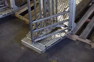


6 I. HARDWARE OVERVIEW ENTER GATE CYLINDER ENTER GATES EXIT/SELECT GATE CYLINDER EXIT/SELECT GATE - 6 -
7 II. PROCESSOR OPERATION OVERVIEW The following examples of processor screens give examples of how to move about the screens and make changes, where needed. UNDERLINED WORDS To move to the screen on the right, the button to the right of the underlined word Extra is pushed. When it is desired to return to a previous screen, a push of the Back button is needed. TAB SCREENS The tabs at the bottom of the screen indicates that various screens can be selected using the corresponding button below each screen tab. The bottom buttons are also used to make a selection when a highlighted option appears at the bottom of the screen. PREFERANCE OR DATA CHANGES When changing a data field, first push the Edit button, this will highlight one of the editable fields. Then using the Arrow buttons, the highlight may be moved to the desired field. Once the desired field has been highlighted, the numeric keypad or the Plus/Minus buttons may be used to make the desired change. After all of the changes have been completed, a single push of the Enter button is required to save the changes. If an accidental change is made, the Undo button may be used to change all of the fields back to the original settings, if pressed prior to pushing the Enter button
 Press to enter menu when tabs are displayed at bottom of window Numeric Select Buttons Press to enter number entries Undo Button Press to undo")
8 III. PROCESSOR OVERVIEW Alarm Button Press to show alarms Display Window Option Buttons (4) Press to enter menu of underlined words Alarm Light Blinks when alarm is disabled or is in an alarm state, on constant when in normal operation Tab Buttons (3) Press to enter menu when tabs are displayed at bottom of window Numeric Select Buttons Press to enter number entries Undo Button Press to undo entry before pressing enter button Enter Button Press to accept entry when an edit has been made Back Button Press once to go back in the menu structure Plus & Minus Buttons Press to toggle between options when editing Arrow Buttons (4) Press to move between editable fields of data in display window. Also scrolls display in review menu Edit Button Press to enter edit mode on any editable screen. Values will appear inversed when in the edit mode - 8 -
9 IV. SETUP & REVIEW SCREENS - 9 -
10 V. CALIBRATION & COMMUNICATION SCREENS
11 Basic Operation VI. Reset alarm (after power downs) 1) After power is reapplied to the controller, the above screen will appear. 2) After pressing the Alarm button two times, the above screen will appear. 3) After pressing the Back button once, the main menu screen will appear

12 Basic Operation VII. Setting the gate mode There are three operating modes for the gates: auto, manual and weigh only. In the manual mode gates are opened or closed by the operator changing their status. The auto mode weighs and based on the settings sends the animal out the exit or select sides. The weigh only mode acts just like the auto but the animals are all sent to the exit side regardless of weight. By default the controller exits to the animal s left, selects to the animals right. 1) After the Select screen and the Set-Sel tab has been selected, pressing the Edit button will highlight the selections and then using the Plus or Minus buttons the selection may be changed to the desired setting. NOTE: If selections are already highlighted, pressing the Edit button will un-highlight the selection. 2) If it is desired to have the entry or exit gates in something other than the automatic mode, than the Sel. Progr. selection must be set to manual setting first, to allow access to change the gate settings in step 2. Basic Operation VIII. View current weight & zero scale 1) The current weight reading of the scale may be read by pressing the Extra and then Scale button
13 2) If there is a need to re-zero the scale this may be done by pressing the zero tab button and then pressing the button beneath the highlighted word zero. After the calibration done appears, the button beneath the highlighted word back may be pressed, which will take you back to the Zero tab screen. Care should be taken when zeroing the scale that no animals are interfering with the reading, which will affect the zero setting and the accuracy of the scale. Basic Operation IX. Entering day number, expected weight & date (New group setup) *WARNING: When these settings are changed, both the historic data in the Review menu and the selected data in Select menu are cleared! 1) The setup screen can be used to check when and how long the current group of animals has been in the building. If at this point, the Back button is used, there will be no effect on the historic data. 2) When a new group of animals is brought into the facility, the above set of screens will be used to track the new historic data for the group. This information will be used to calculate day numbers, growth and inventory within the review screens. Basic Operation X. Enter select weight
14 1) The Prog and Set-Sel screens will be used to select the weight that it is desired to have sorted off into a separate pen. 2) After choosing the Sel. Market option, the minimum desired weight and the maximum number of animals that are needed to be selected are chosen. Next, the select option of either now or between dates is available. 3) If the between dates option is selected two additional screens will be displayed, allowing the user to specify when the selection is to begin and stop. Additional selections are available within the Select Program. These options provide some of the following choices: Select Market selects those animals over a given minimum weight and it can be specified the maximum number of animals selected. If the scale assumes that two animals are on the scale, using the expected weight input, then they will be returned to the Exit side of the sorter. Select Market + selects those animals over a given minimum weight and it can be specified the maximum number of animals selected. If the scale assumes that two animals are on the scale, using the expected weight input, then they will be selected to the Select side of the sorter. Exit All - weights and then releases each animal to the Exit side of the sorter. The measured weights are then saved and can be reviewed. Manual - No weights are measured and must be used to manually control the Enter and Exit/Select gates. Select All - weights and then releases each animal to the Select side of the sorter. The measured weights are then saved and can be reviewed. Select Small - selects all those animals under a given maximum weight. Select Small Mean - selects those animals under a given maximum weight and it can be specified the maximum quantity of animals selected
15 Basic Operation XI. Enter markspray weight 1) The Prog and Set-Sel screens will be used to select the animals that it is desired to have marked using the markspray. 2) After choosing the Sel. Markspray option, the first option is the mark mode. This provides an option for which animals are needed to be marked. Next, the select option of either now or between dates is available. 3) If the between dates option is selected two additional screens will be displayed, allowing the user to specify when the selection is to begin and stop. Additional selections are available within the Set-Markspray Program. These options provide some of the following choices: a. Off turns the markspray off. b. Once provides one shot of the dye, which might be used while priming or trouble shooting the markspray equipment. c. Below marks all those animals that are below the markspray set-point, which might be used to mark those animals that may require medical attention or not keeping up with the group. d. Above - marks all those animals that are above the markspray set-point, which might be used to mark those animals that just missed the selection weight and might be used to finish a load. e. All - marks all the animals that are weighted across the scales, which might be used to verify which animals crossed the scale during a given time frame
16 Basic Operation XII. Weight review 1) The Actual Individual screen is used to view the weights of all the animals that were weighted across the scales. The Select Individual screen is used to view the weights of the animals that were weighted and selected. The Weight screen is an overview screen showing the average weight and number of animals that were selected under the Select column. The Actual column shows the expected weight and the number of animals that went to the exit side of the sorter. 2) The Day-Review screen gives the days that the group has been in the facility, the average animal weight per day, the growth rate per day, and the number of animals that were weighted each day across the scales. 3) The Expected Class screen gives the average weight as a percentage of the expected weight, and the number of animals that were weighted within each weight group. 4) The Total Class screen gives the total weight as a percentage of the expected weight, and the number of animals that were weighted within each weight group

17 Technical Notes XIII. Relationship between expected and select weights The expected weight is an editable setpoint that is used as a basis to control gate operation (see Installation set-up, setting gate times and weight percentages). The expected weight should be thought of as the average weight of all the animals that will be weighed by the sort unit. Every hour the processor will automatically update the expected weight to reflect the average weight of all the animals weighed in the prior 24 hours. The select weight is an operator editable feature that is the weight at which the operator wants to select the animals. The Expected Weight Range includes both the Lower Expected Weight Range and the Upper Expected Weight Range. The lower expected weight range is between the expected weight and a percentage of the expected weight that is defined by the operator. The upper expected weight is between the expected weight and 1.4 times the expected weight. Above 1.4 times the expected weight, the controller assumes there are two animals in the scale and opens the gate to the exit side to send them to the feed court. The Selection Weight Range is simply all weights heavier than the Select Weight Setting. The Range of weights that will allow selection is the range of weights that are within BOTH the Selection Weight Range and the Expected Weight Range. When setting the expected weight for the first time, perform the following math to insure that the unit will have the proper parameters to function as desired
18 1) Determine the percentage of expected weight that has been set in the Enter Gate parameters (see the Installation set-up section, gate set-up for information to help navigate to desired display). Record this number for use in the following formula. 2) Calculate the approx. average weight of the pen to be weighed by measuring 10 animals. Use this number as your expected weight in the formula and input in the setup menu. Formula A Expected Weight (from #2 above) x. Enter gate percentage (from #1 above) as a decimal This is the lightest animal that will activate the unit Formula B Expected Weight (from #2 above) x 1.40 Percentage of expected weight (as a decimal) that will Cause the control to assume two animals are in the Scale, resulting in the gate opening to the exit side. An animal more heavy than this is seen as 2 and will Be exited back to the light side. These answers give you the Expected Weight Range, from the lightest (Formula A) to the heaviest (Formula B) weights that any animal in the group may be and still allow normal selection using the expected weight entered. If you believe this range does not cover all the animals in the group, adjust the expected weight accordingly and repeat the formulas until you are confident you have an expected weight number that will work for your application. The select weight you choose must be below 1.4 times the expected weight to have any effect. For example, if you have chosen an expected weight of 200 lbs. and the enter gate is set to close after 60% of the expected weight is attained, the Expected Weight Range is 120 lbs. (200 x.6) to 280 lbs. (200 x 1.4). The select weight must be within this range for the unit to work properly. If a select weight of 250 lbs. is chosen, the Select Weight Range is all weights above 250 lbs. and within the expected weight range, yielding a Range of weights that will allow selection from 250 lbs. to 280 lbs. NOTE: If a select weight is chosen that is more than 140% of the expected weight no animals will be selected. Additional Examples: 1) 100 lb. Expected Wt.; 60% gate; = 60 lb. to 140 lb. Expected Wt Range 125 lb. Select Wt. = 125 lb. to 140 lb. Range that allows selection 2) 75 lb. Expected Wt. ; 50% gate; = 37.5 lb. to 105 lb. Expected Wt Range 90 lb. Select Wt. = 90 lb. to 105 lb. Range that allows selection
19 3) 180 lb. Expected Wt.; 60% gate; = 108 lb. to 252 lb. Expected Wt Range 170 lb. Select Wt. = 170 lb. to 252 lb. Range that allows selection 4) 180 lb. Expected Wt.; 60% gate; = 108 lb. to 252 lb. Expected Wt Range 260 lb. Select Wt. = greater than 260 lb. to less than 252 lb. results in a Range that will never select hogs NOTE: Herd Variance - If the lightest animal is less than half the weight of the heaviest animal presort is recommended to separate small animals out. WARNING: When either the day number or expected weight settings are changed both the historic data in the Review menu and the selected data in Select menu is cleared!
20 Technical Notes XIV. Relationship between filter and stability The sensitivity of the scale is controlled with two items, Filter and Stability. While these are both editable features, it is not recommended that these features be changed unless special circumstances exist. This section is meant to educate the operator and aide in trouble shooting. During normal operation the scale takes multiple weight samples. Filter refers to the number of seconds the weight must remain within a range to be stable. This range is set with the Stability setting. Stability is the percentage of the expected weight that the reading from the scale may vary. The default settings from the factory are: Filter: 2.0 Stability:
21 Technical Notes XV. Gate operation and variable parameters The scale utilizes gates to control the animal s movement into the unit, then holding the animal while weighing takes place, and finally sending the animal out of the unit through one of two exit directions. Properly set, this cycle takes place automatically, with no trauma to the animals. The settings allow operator input that can fine-tune the unit to the special needs of a particular operation. Modes There are three operating modes for the gates: auto, manual and weigh only. In the manual mode gates are open or closed. The auto mode weighs and based on the settings sends the animal out the exit or select direction. The weigh only mode functions just as the auto mode but all the animals are sent in the exit direction regardless of weight. Entry Gates The animals enter the unit through a pair of gates. During normal operation these enter gates are in an open position until an animal enters and the scale registers the new weight being added. When a weight is sensed that is determined by the operator as a percentage of expected weight, the processor will close the entry gates to confine the animal for weighing after a delay set by the operator. More detailed information concerning how to edit expected weight and delay seconds is covered in the Installation set-up section under setting gate times and percentages. The percentage of expected weight is set to 50% by the factory. This means that when 50% or half of the expected weight is detected in the scale the delay seconds countdown begins. The delay seconds is set to 5 seconds by the factory. The delay should allow enough time for the animal to completely enter the scale without allowing another animal to sneak in behind. Safety As a safety feature, if the enter gates are not fully closed 4 seconds after the processor signals to close them, the processor assumes an animal has been caught in the gates and they reopen and the process begins again. This safety is based on a reed switch located on the enter gate air cylinder. Exit / Select Gate After the animal s weight is determined, it exits the unit through a gate that swings to the left or right allowing the unit to direct the animal to one of two pens. By default the processor exits to the animals to the left and selects the animals to the right. This gate is referred to as the Exit / Select Gate and it s opening direction is determined by the weight of the animal and the operator s desired select weight (more information on this subject in Technical notes, expect / select weight). After the gate opens to let the animal leave the scale, it refers to the gate settings for closing instructions. This gate uses the same type of settings as the enter gates with the exception that in this case the percent of expected weight is set so that when the scale reads a weight below this percentage weight setting it begins the delay to close. Note that the processor actually views this gate as two separate gates (exit gate and select gate) and allows these settings to be edited separately for each gate (more detailed information concerning how to edit both of these features is covered in the Installation set-up section under setting gate
22 times and percentages). The factory settings for these gates are the same, 5 seconds after weight drops below 50% percent of expect weight. Adjusting Gates for Speed, Pressure and Opening Width The opening and closing speeds of both the enter gate and the exit / select gates are adjustable using the flow controls on the air cylinders. These controls are set at the factory but can be adjusted on site if desired. These flow controls regulate the air leaving the cylinder rather than entering the cylinder, so if you are trying to change the opening speed you adjust the flow control on the end of the cylinder with the close airline connected. To restrict the air flow (slowing movement) turn the Adjusting Gates for Speed, Pressure and Opening Width adjustment in a clockwise direction. The enter gate has its own air pressure regulator to control the force used to close the gates. During regular operation the air pressure should be set at 40psi. When smaller animals are being run through the unit, the entry gate opening can be reduced to lower the possibility of two animals entering at once. Restrict the opening by pinning the chain attached to the entry gate linkage, in a link making the chain shorter. Installation set-up
23 XVI. Setting date & time 1) The clock and date can be set using the General screen. The date will be set using the daymonth-year format. The Clock Type may be set to either 12 or 24 hour setting. If the Clock Type is set to 12 hour, than the Time will be set to the standard, shown format, using the AM/PM display. If the Clock Type is set to 24 hour, than the Time will be displayed in a military format, which would be 14:35 for the same time as shown above. NOTE: When entering the Time, a period (. ) will be used to enter the hypen ( : ). Installation set-up XVII. Setting gate times and percentages WARNING: DO NOT CHANGE THE GATE ADDRESS [Example: Select Gate addr. 0.3] NOTE: WHILE THE EXIT/SELECT GATE IS PHYSICALLY ONLY ONE GATE THAT MOVES TWO DIRECTIONS, THE CONTROLLER HANDLES IT AS TWO SEPARATE GATES 1) The gate times and percentages can be set using the Gates screen. If at any time the gate addresses are accidentally changed, they should be returned to the defaults, shown below. 2) Each gate may set to close after a given time and percentage of the expected weight. EXAMPLE: If the expected weight has been set to 200 pounds and an animal starts to step onto the scale, as soon as the scale is measuring 120 pounds, the scale waits one second more and than starts closing the Enter Gate. After the animal has been weighted, then either the Exit or Select Gate will open, as determined by the weight and gate mode, after enough of the animals weight has left the scale for the amount of weight still measured by the scale to have dropped below 100 pounds, the scale waits five more seconds and than starts closing the Exit/Select Gate
24 Installation set-up XVIII. Calibrating the scale This calibration is done at the factory and should only be required if a control board or load cell are changed. Use these directions in the event they need to be re-entered. The calibration process will require the use of an object of known weight that can be placed in the scale. It is recommenced that the object be at least 200 lbs. 1) If there are animals moving across the scale, it will be necessary to close the sorter to prevent the animal activity from influencing the calibration process. First, the controller must be set to the Manual setting. 2) Next, the Enter and the Exit/Select gates will need to be changed to the Closed setting. 3) If the Zero screen is not showing a reading of 0, then the button beneath the highlighted Calibration button needs to be pressed to first zero the scale. After the scale has been zeroed, press the Span button, then the known weight may be loaded into the basket. If the Calibration Weight readout does not match the Weight Readout, then, using the numeric keypad, the reading needs to be changed and then press the Calibration button. After the Calibration Weight has been set, the weight should be removed and the Zero screen rechecked to verify that the reading returns to 0. 4) After completion of the calibration process, the controller may be returned to the desired Select Program option
25 Installation set-up XIX. Setting markspray times WARNING: DO NOT CHANGE THE MARKSPRAY ADDRESS [Example: Markspray addr. 0.4] 1) The markspray time can be set using the Install screen. If at any time the markspray address is accidentally changed, it should be returned to the default, shown above
26 Trainer Operation XX. Setup and operation The sorter can either be set for the use of the Trainer gate or the markspray and a change to both addresses is required for proper operation of either. The following are the required address settings for the desired mode of operation: Trainer Markspray Markspray address: 0.0 Markspray address: 0.4 Ejector address: 0.4 Ejector address: 0.0 NOTE: If both addresses are left at 0.4, both the Trainer gate and the markspray will operate, but the markspray will continue to mark through out the movement of the Trainer gate. 1) This sample change is changing from the markspray usage to the Trainer gate but to change from the Trainer gate to markspray will be performed using the same steps. After bringing up the Install screen and selecting the Marker tab, highlight the Markspray address and change it from 0.4 to ) Next, select the Ejector tab and change the Ejector relay address from 0.0 to 0.4. Caution should be taken that the Ejector input address is not changed. 3) The Start timing can be set for the time delay between the exit / select gate opening, and operation of the Trainer gate. 4) The Close timing can be set to delay the Enter gate from opening until after the Trainer gate has been fully retracted to avoid premature entry to the scale. 5) To turn the Trainer gate off, it is necessary to change the Ejector relay address to
27 This page intentionally left blank for notes
28 MADE TO WORK. BUILT TO LAST. Contact your nearby Chore-Time distributor or representative for additional parts and information. Chore-Time Hog Production Systems A Division of CTB, Inc. P.O. Box 2000, Milford, Indiana U.S.A. Phone: (574) Fax: (574) hog@choretime.com Internet: Printed in the U.S.A.
4 and 8 Station PDS Control Installation & Operators Manual
 4 and 8 Station PDS Control Installation & Operators Manual 1402-15 11/2000 June 2003 MW1402C Chore-Time Warranty 4 and 8 Station PDS Control Chore-Time Warranty Chore-Time Equipment ( Chore-Time ) warrants
RAM 4021 Operation Manual
 RAM 4021 Operation Manual Worldwide Manufacturer of Gas Detection Solutions TABLE OF CONTENTS RAM 4021 For your safety...3 Description...3 Set-up mode...4 Annunciator lights/alarms...4 Operation...5 Calibration...6
Portable Gas Monitor GX User Maintenance Manual (H4-0050)
") H4E-0050 Portable Gas Monitor GX-8000 User Maintenance Manual (H4-0050) Need of Maintenance and Servicing This gas monitor must be maintained in a normal state at all times to prevent accidents due to
H4E-0050 Portable Gas Monitor GX-8000 User Maintenance Manual (H4-0050) Need of Maintenance and Servicing This gas monitor must be maintained in a normal state at all times to prevent accidents due to
PDS Control 4 and 8 Station Pneumatic Drinking System Installation and Operators Manual
 Pneumatic Drinking System Installation and Operators Manual August 2009 Warranty Warranty Chore-Time Poultry Production Systems, a division of CTB, Inc., ( Chore-Time ), warrants each new CHORE-TIME product
Apex Evaporator Manual
 Apex Evaporator Manual Table of Contents I. Handling/Transportation of Apex II. Placing the evaporator III. Connecting Power to the control Panel IV. Placing the control panel and weather station V. Attaching
SPECIFICATIONS APCEPH1
 APCEPH1 ph CONTROLLER SPECIFICATIONS APCEPH1 Input voltage 120 Volts AC Maximum amperage 14.5 amps @ 120 VAC ph Accuracy +/- 0.2 ph ph Control range Adjustable 4.5 8.5 ph Weight < 1 lbs Dimensions 3" x
RAM Operation Manual. Worldwide Manufacturer of Gas Detection Solutions
 RAM 4021 Operation Manual Worldwide Manufacturer of Gas Detection Solutions TABLE OF CONTENTS RAM 4021 For Your Safety... 2 Description.... 2 Setup Mode.... 2 Lights/Alarms.... 3 Operation.... 4 Calibration....
PDS Control 4 and 8 Station Pneumatic Drinking System Installation and Operators Manual
 Pneumatic Drinking System Installation and Operators Manual January 2015 Limited Warranty Limited Warranty Chore-Time Group, a division of CTB, Inc. ( Chore-Time ) warrants new CHORE-TIME Cage and Cage
RAM 4021-DPX Operation Manual
 RAM 4021-DPX Operation Manual Worldwide Manufacturer of Gas Detection Solutions TABLE OF CONTENTS ABL 4021-DPX / RAM 4021-DPX For Your Safety... 3 Description... 3 Setup Mode... 4 Lights/Alarms... 4 Operation...
RAM Operation Manual. Worldwide Manufacturer of Gas Detection Solutions
 RAM 4021 Operation Manual Worldwide Manufacturer of Gas Detection Solutions TABLE OF CONTENTS RAM 4021 For Your Safety... 2 Description.... 2 Setup Mode.... 2 Lights/Alarms.... 3 Operation.... 4 Calibration....
RAM 4021-PR. Operation Manual. Worldwide Manufacturer of Gas Detection Solutions
 RAM 4021-PR Operation Manual Worldwide Manufacturer of Gas Detection Solutions TABLE OF CONTENTS RAM 4021-PR For Your Safety... 2 Description.... 2 Setup Mode.... 2 Lights/Alarms.... 3 Operation.... 4
Digital Vacuum Regulator
 Temperature Control for Research and Industry Digital Vacuum Regulator User s Manual Model DVR-380 INDEX SECTION PAGE SAFETY NOTICES................................................. 3 1. QUICK OPERATING
SHUR-STEP STAIRWAY and Platform
 SHUR-STEP STAIRWAY and Platfm (Patented) Installation Instructions Stiffened and Unstiffened Narrow Wide Crugated Flat-Bottom Grain Bins and Commercial Hopper Bins (above the Hopper) February 203 MLD7D
OPERATING INSTRUCTIONS V 5.3
 1 OPERATING INSTRUCTIONS V 5.3 DM 06/ 07 EGO 06/ 07 ION /SP8 MINI Proto Matrix 07 Proto Rail Shocker Seventh Element, Inc WARNING Failure to follow directions may result in damage to board. Do not pull
6 digital caliper with case
 6 digital caliper with case Model 98563 Set up And Operating Instructions Diagrams within this manual may not be drawn proportionally. Due to continuing improvements, actual product may differ slightly
Operating Instructions for BAIR22-6 AIR-POWERED CRIMPING TOOL
 Operating Instructions for BAIR22-6 AIR-POWERED CRIMPING TOOL Read and understand all of the instructions and safety information in this manual before operating or servicing this tool. Table of Contents
RAM Operation Manual
 RAM 4021-1 Operation Manual Worldwide Manufacturer of Gas Detection Solutions TABLE OF CONTENTS RAM 4021-1 For Your Safety... 2 Description... 2 Setup Mode... 3 Lights/Alarms... 3 Operation... 4 Calibration...
Touch Screen Guide. OG-1500 and OG Part # T011
 Touch Screen Guide OG-1500 and OG-2000 Part # 9000000.T011 Effective 11/2010 External View Internal View 1. Transducer Banks 2. Oxygen Sensor 3. PLC These are the two manifolds with three (3) transducers
UE- 90- X X X X X X O P E R AT I N G M A N UA L 0 TO 90 HYDRAULIC UPENDER
 UE- 90- X X X X X X O P E R AT I N G M A N UA L ADDRESS 2230 Brush College Road Decatur, IL 62526 Phone: 217-423-6001 Fax: 217-422-1049 E-mail: sales@alignprod.com www.alignproductionsystems.com UE-90-XXXXXX
Owners Manual Models: 075-AQF-CX. Aquatrol Backwashing Catalytic Carbon Filter. Visit us online at.
 Visit us online at www.uswatersystems.com Aquatrol Backwashing Catalytic Carbon Filter Owners Manual Models: 075-AQF-CX REVISION # 1.0 REVISION DATE October 11, 2017 US Water Systems, Inc. 1209 Country
MODEL 100 NITROGEN INFLATION CART
 MODEL 100 NITROGEN INFLATION CART Installation & Operation Information Branick Industries, Inc. 4245 Main Avenue P.O. Box 1937 Fargo, North Dakota 58103 REV120106 P/N: 81-0113 TABLE OF CONTENTS SAFETY
ELIMINATOR INSTRUCTIONS Table of Contents
 ELIMINATOR INSTRUCTIONS Table of Contents 1. PRACTICE MODE A. Toggling from Full to Pro Tree B. Toggling from 1 to 2 Users C. Toggling from Auto to Manual Reset D. Setting the Delay Boxes E. Setting a
Sweeper Dual Control. Automatic Sweeper Switching System SW SERIES SWEEPERS SW-4815 SW-4820 SW-4825 MAGUIRE PRODUCTS INC.
 MAGUIRE PRODUCTS INC. SW SERIES SWEEPERS For SW Series Sweeper Models: SW-4815 SW-4820 SW-4825 Sweeper Dual Control Automatic Sweeper Switching System INSTRUCTION AND OPERATION MANUAL Copyright Maguire
User s Guide Temperature Sensor Converter TSC-599
 User s Guide Temperature Sensor Converter TSC-599 ILX Lightwave Corporation 31950 Frontage Road Bozeman, MT, U.S.A. 59715 U.S. & Canada: 1-800-459-9459 International Inquiries: 406-556-2481 Fax 406-586-9405
Iron Filter Installation / Operation Manual
 Iron Filter Installation / Operation Manual BrassMaster and BrassMaster Plus Technical Video Library: http://watercontrolinc.com/residential-technical-support/residential-technical-videos BrassMaster technical
CSA Sample Draw Aspirator Adapter Operator s Manual
 30-0951-CSA Sample Draw Aspirator Adapter Operator s Manual Part Number: 71-0367 Revision: 0 Released: 4/30/15 www.rkiinstruments.com WARNING Read and understand this instruction manual before operating
MODEL CALIBRATION GAS DELIVERY SYSTEM
 MODEL 1200-26 CALIBRATION GAS DELIVERY SYSTEM Sierra Monitor Corporation 1991 Tarob Court, Milpitas, CA 95035 (408) 262-6611 MODEL 1200-26 CALIBRATION GAS DELIVERY SYSTEM APPLICABILITY & EFFECTIVITY This
HAI UPB 15A Relay Switch and Auxiliary Switch Installation and Operating Instructions
 HAI UPB 15A Relay Switch and Auxiliary Switch Installation and Operating Instructions For the following Models: 40A00-1 HAI 15A Relay Switch (referred to as HAI UPB Wall Switch, in this document), and
CF-SERIES HIGH FLOW REGULATORS
 CF-SERIES HIGH FLOW REGULATORS Owner s Manual Printed in U.S.A February 2014 Publication No. OM-CA-3 REV.4 1.3 Copyright Notice 1.0 Introduction The CF-Series are high flow regulators for critical applications
Yoke Block Instruction Manual
 Yoke Block Instruction Manual ! WARNING IMPORTANT: READ MANUAL COMPLETELY BEFORE OPERATING THIS DEVICE This manual contains instructions on periodically required checks to be performed by the user. These
92831 TEL: (714) FAX:
 FAX:") Document N0. 1800-03 Copyright 2010 Terra Universal Inc. All rights reserved. Revised Sept. 2010 Terra Universal, Inc. TerraUniversal.com 800 S. Raymond Ave. Fullerton, CA 92831 TEL: (714) 578-6000 FAX:
Document N0. 1800-03 Copyright 2010 Terra Universal Inc. All rights reserved. Revised Sept. 2010 Terra Universal, Inc. TerraUniversal.com 800 S. Raymond Ave. Fullerton, CA 92831 TEL: (714) 578-6000 FAX:
VOLLEYBALL SPIKE TRAINER. Assembly Instructions. Owner s Manual. Model # VST-300. Club Volleyball Gear. For fixed-height Basketball Hoop Systems
 VOLLEYBALL SPIKE TRAINER Model # VST-300 For fixed-height Basketball Hoop Systems Assembly Instructions Basketball Hoop System Not Included Owner s Manual Club Volleyball Gear 18434 Technology Drive, Morgan
TOP VALVE. Pat. #5,857,486 & 5,944,050. Mid-Range Pressure PSIG Back Pressure and Pressure Relief Valves. Instruction Manual
 TOP VALVE Pat. #5,857,486 & 5,944,050 Mid-Range Pressure 50 232 PSIG Back Pressure and Pressure Relief Valves Instruction Manual Please Note: This instruction manual provides detailed information and instructions
GETZ EQUIPMENT INNOVATORS PART NO.: 9G59554 MODEL: MS 36 SC-R HYDROSTATIC TEST PUMP
 GETZ EQUIPMENT INNOVATORS PART NO.: 9G59554 MODEL: MS 36 SC-R HYDROSTATIC TEST PUMP LIMITED WARRANTY Getz Equipment Innovators warrants its products, and component parts of any product manufactured by
RK-IR Sample Draw Aspirator Adapter Operator s Manual
 30-0951RK-IR Sample Draw Aspirator Adapter Operator s Manual Part Number: 71-0018RK Revision: A Released: 6/2/10 www.rkiinstruments.com Product Warranty RKI Instruments, Inc. warrants gas alarm equipment
TR Electronic Pressure Regulator. User s Manual
 TR Electronic Pressure Regulator Page 2 of 13 Table of Contents Warnings, Cautions & Notices... 3 Factory Default Setting... 4 Quick Start Procedure... 5 Configuration Tab... 8 Setup Tab... 9 Internal
VOLLEYBALL SPIKE TRAINER. Assembly Instructions. Owner s Manual. Model # VST-200. Club Volleyball Gear. For height-adjustable Basketball Hoop Systems
 VOLLEYBALL SPIKE TRAINER Model # VST-200 Basketball Hoop System Not Included For height-adjustable Basketball Hoop Systems Assembly Instructions Owner s Manual Club Volleyball Gear 18434 Technology Drive,
Operation Manual. Pro He Alarm TM. Helium Analyzer. Rev 08.17
 Operation Manual Pro He Alarm TM Helium Analyzer Rev 08.17 If you have any questions on this equipment please contact Technical Support at: Nuvair 1600 Beacon Place Oxnard, CA 93033 Phone: 805-815-4044
Digital Vacuum Regulator
 Temperature Control for Research and Industry Digital Vacuum Regulator User s Manual Model DVR-280 INDEX SECTION PAGE 1. QUICK OPERATING INSTRUCTIONS............................. 3 KEM-NET DATA LOGGING
PARK AVENUE 7' POOL TABLE WITH TABLE TENNIS & BENCHES ASSEMBLY INSTRUCTIONS
 PARK AVENUE 7' POOL TABLE WITH TABLE TENNIS & BENCHES ASSEMBLY INSTRUCTIONS NG2530PR THANK YOU! Thank you for purchasing this product. We work around the clock and around the globe to ensure that our products
VOLLEYBALL SPIKE TRAINER. Assembly Instructions. Owner s Manual. Model # VST-400. Club Volleyball Gear
 VOLLEYBALL SPIKE TRAINER Model # VST-400 Wall-mount Volleyball Spike Trainer with 28 height adjustment range Assembly Instructions Owner s Manual Club Volleyball Gear 18434 Technology Drive, Morgan Hill,
Calibration Gas Instrument INSTRUCTION MANUAL. Release I. Advanced Calibration Designs, Inc.
 Advanced Calibration Designs, Inc. Calibration Gas Instrument INSTRUCTION MANUAL Release I www.goacd.com Instruction Manual Gas Generator Release I TABLE OF CONTENTS I. General Description Page 2 II. Start-Up
T i m i n g S y s t e m s. RACEAMERICA, Inc. P.O. Box 3469 Santa Clara, CA (408)
") RACEAMERICA T i m i n g S y s t e m s Demo Tree Controller Owner s Manual Models 3204D, 3204DW & 3204DX Rev D RACEAMERICA, Inc. P.O. Box 3469 Santa Clara, CA 95055-3469 (408) 988-6188 http://www.raceamerica.com
RACEAMERICA T i m i n g S y s t e m s Demo Tree Controller Owner s Manual Models 3204D, 3204DW & 3204DX Rev D RACEAMERICA, Inc. P.O. Box 3469 Santa Clara, CA 95055-3469 (408) 988-6188 http://www.raceamerica.com
Parts Manual. Frusheez Machines
 Parts Manual Frusheez Machines Model No. 1414 and 1416 Model 1414 Model 1416 10700 Medallion Drive, Cincinnati, Ohio 45241-4807 USA Part No. 110007 ORDERING SPARE PARTS 1. Identify the needed part by checking
Nitrogen Supply System
 ATMOSCOPE Nitrogen Supply System NS500 Users Guide Copyright 2001 EDSYN, INC. ATMOSCOPE Nitrogen Supply Systems TABLE OF CONTENTS Introduction............................. 3 General Information.......................
Golf Performance Monitors. PureContact Operating Guide. Version of 9
 PureContact Operating Guide Version 5.1 www.zelocity.com 1 of 9 PureContact Metrics: Measured Ball Velocity Carry Distance Other PureContact Features: Instantly, Accurately Displays & Records Critical
In Vivo Scientific, LLC INSTRUCTION MANUAL
 CO 2 Controller In Vivo Scientific, LLC INSTRUCTION MANUAL CONTENTS CONTENTS...1 ABOUT THIS MANUAL...2 INTRODUCTION...2 Cautions and Warnings...2 Parts List...2 Unpacking...2 INSTRUMENT DESCRIPTION...3
Yoke Block Instruction Manual
 Yoke Block Instruction Manual ! WARNING IMPORTANT: READ MANUAL COMPLETELY BEFORE OPERATING THIS DEVICE This manual contains instructions on periodically required checks to be performed by the user. These
Overview. Front Panel: Keypad and Display
 Overview The GA-200B is an analyzer that integrates a gas sampling system with sensors to measure and display the concentrations of oxygen and carbon dioxide in a sample as the percentage of a gas in the
BT PAINTBALL DESIGNS, INC. 570 MANTUA BLVD., SEWELL, NJ
 Rip Clip Manual_2.qxp 4/15/08 11:00 AM Page a BT PAINTBALL DESIGNS, INC. 570 MANTUA BLVD., SEWELL, NJ 08080 WWW.BTPAINTBALL.COM Rip Clip Manual_2.qxp 4/15/08 11:00 AM Page b BT Paintball would like to
Operation Manual. Pro CO 2 Analyzer. Carbon Dioxide Analyzer. Rev
 Operation Manual Pro CO 2 Analyzer Carbon Dioxide Analyzer Rev. 10.17 Quick Reference Guide READ ENTIRE MANUAL BEFORE USE 1. To switch on, hold the On/Off button until the display powers up. 2. To turn
Accu-Tab PowerBase 3012AT by Axiall Corporation
 Accu-Tab PowerBase 3012AT by Axiall Corporation Installation and Operating Instructions DANGER: DO NOT MIX CHEMICALS! The PowerBase 3012AT chlorinator system is designed for use with Axiall Corp. approved
Rip Clip Manual_2.qxp 4/15/08 11:00 AM Page c
 Rip Clip Manual_2.qxp 4/15/08 11:00 AM Page b Rip Clip Manual_2.qxp 4/15/08 11:00 AM Page c Rip Clip Manual_2.qxp 4/15/08 11:00 AM Page 1 BT Paintball would like to thank you for your purchase of the BT
700 SERIES BMS II BUBBLER MONITORING SYSTEM
 1 700 SERIES BMS II BUBBLER MONITORING SYSTEM VISIT OUR WEBSITE AT SIGMACONTROLS.COM 700 SERIES BMS II MANUAL 062114 2 TABLE OF CONTENTS INTRODUCTION 3 Physical Specifications WIRING 5 PROGRAMMING & SETUP..
HAS2400 Hepa Air Scrubber
 HAS2400 Hepa Air Scrubber Diamonds Products 15 SW 40th Ave Great Bend, KS 67530 USA Toll Free: (866) 539-1694 Local: (620) 792-4542 Purchase Date: Serial Number: Purchased From: The DIAMOND HAS2400 HEPA
92831 TEL: (714) FAX:
 FAX:") Document No. 1800-75 Respiration Test Chamber Copyright 2010 Terra Universal Inc. All rights reserved. Revised September 2010 Terra Universal, Inc. TerraUniversal.com 800 S. Raymond Ave. Fullerton, CA
Document No. 1800-75 Respiration Test Chamber Copyright 2010 Terra Universal Inc. All rights reserved. Revised September 2010 Terra Universal, Inc. TerraUniversal.com 800 S. Raymond Ave. Fullerton, CA
Accu-Tab Systems 2000 P Series by Axiall Corporation
 Accu-Tab Systems 2000 P Series by Axiall Corporation Installation and Operating Instructions Models 2075 P 2150 P For NSF/ANSI-Standard 61 NSF STANDARD 61 applications use NSF/ANSI Standard 60 listed Axiall
Psyclone TM. Protimeter Thermo-Hygrometer. GE Sensing. Operating Manual. INS7800, Rev. A (September 2007)
") GE Sensing Psyclone TM Protimeter Thermo-Hygrometer Operating Manual INS7800, Rev. A (September 2007) Psyclone is a Protimeter product. Protimeter has joined other GE high-technology sensing businesses
GE Sensing Psyclone TM Protimeter Thermo-Hygrometer Operating Manual INS7800, Rev. A (September 2007) Psyclone is a Protimeter product. Protimeter has joined other GE high-technology sensing businesses
Please Do Not Return This Product To The Store!
 MODEL NUMBER: GM000W - GAMEMAKER TORCH O W N E R ' S M A N U A L PLEASE READ AND FOLLOW THIS MANUAL IN ITS ENTIRETY BEFORE USE. DOING SO WILL PROVIDE HELPFUL HINTS THAT WILL AID IN GETTING MAXIMUM USE
ACV-10 Automatic Control Valve
 ACV-10 Automatic Control Valve Installation, Operation & Maintenance General: The Archer Instruments ACV-10 is a precision automatic feed rate control valve for use in vacuum systems feeding Chlorine,
Owner s Manual Humiport 10/20
 4201 Lien Rd Madison, WI 53704 Owner s Manual Humiport 10/20 Installation, Operation & Service Instructions Read and Save These Instructions The Phoenix Humiport line of ThermoHygrometers offers the restoration
INSTRUCTION MANUAL. Includes: OPERATION SETUP USE & CARE SERVICE. SPORTS ATTACK LLC
 Electronic Baseball Pitching Machine baseball INSTRUCTION MANUAL PART NO. B-EHABA-100 REV022111 INSTRUCTION MANUAL Includes: OPERATION SETUP USE & CARE SERVICE SPORTS ATTACK LLC 800-717-4251 www.sportsattack.com
Triple Tine Mechanical Grapple
 Attachment Solutions Triple Tine Mechanical Grapple Operators Manual KENCO Mechanical Grapple Operation Manual 1 TABLE OF CONTENTS 170 State Route 271 Section I. General Information.... 3 Section II. Safety...
Revolution Gurney Attachment
 Revolution Gurney Attachment PART NUMBER: F-30RSA-S2 (2nd SERIES) WEIGHT CAPACITY: 350 POUNDS - STANDARD REVOLUTION 300 POUNDS - DEEP DRAFT REVOLUTION MANDATORY LEAVE THIS MANUAL WITH LIFT OWNER Read &
Remington 700. Disclaimer Limited Warranty Satisfaction Guarantee Installation Instructions
 Remington 700 Disclaimer Limited Warranty Satisfaction Guarantee Installation Instructions WARNING: Failure to properly install your trigger and ensure proper safety functionality could result in an unsafe
NB/NBR NITROGEN BOOSTER FOR AVIATION SERVICE
 NB/NBR NITROGEN BOOSTER FOR AVIATION SERVICE INSTALLATION, OPERATION & MAINTENANCE MANUAL INTERFACE DEVICES, INC. 230 Depot Road, Milford, CT 06460 Ph: (203) 878-4648, Fx: (203) 882-0885, E-mail: info@interfacedevices.com
Inventory User Guide
 Inventory User Guide User Guide ~ Table of Contents ~ Sign On/Select Facility Rates & Inventory Update Tee Times Load Tee Times AutoLoad Schedule Rate Fences Dashboards Revenue At Risk, Rounds & Revenue,
TOP VALVE. Pat. #5,857,486 & 5,944,050. High Temperature: max. 300 F (149 C) Back Pressure And Pressure Relief Valves. Instruction Manual
 Back Pressure And Pressure Relief Valves. Instruction Manual") TOP VALVE Pat. #5,857,486 & 5,944,050 High Temperature: max. 300 F (149 C) Back Pressure And Pressure Relief Valves Instruction Manual PLEASE NOTE: This instruction manual provides information and instructions
TOP VALVE Pat. #5,857,486 & 5,944,050 High Temperature: max. 300 F (149 C) Back Pressure And Pressure Relief Valves Instruction Manual PLEASE NOTE: This instruction manual provides information and instructions
Accu-Tab Systems 1000 Series by Axiall Corporation
 Accu-Tab Systems 1000 Series by Axiall Corporation Installation and Operating Instructions Model 1050 DANGER: DO NOT MIX CHEMICALS! The Accu-Tab chlorinator is designed for use with Axiall approved tablets
Pegas 4000 MF Gas Mixer InstructionManual Columbus Instruments
 Pegas 4000 MF Gas Mixer InstructionManual Contents I Table of Contents Foreword Part I Introduction 1 2 1 System overview... 2 2 Specifications... 3 Part II Installation 4 1 Rear panel connections...
3800 SERIES END SUCTION PUMP REPAIR PARTS INDEX. Model Model 3804
 Model 3801 Model 3804 3800 SERIES END SUCTION PUMP REPAIR PARTS INDEX NOTE! To the installer: Please make sure you provide this manual to the owner of the equip ment or to the responsible party who maintains
GAS FRYER Instruction Manual Model #5099NS
 Part No. 89932 Revised: March 2004 GAS FRYER Instruction Manual Model #5099NS Cincinnati, OH 45241-4807 USA GAS SAFETY PRECAUTIONS GAS FUNNEL CAKE FRYER 2 MODEL #5099NS GAS FUNNEL CAKE FRYER SAFETY PRECAUTIONS
StockWeigh 500 D3632 US-B
 OPERATORS MANUAL DIGI-STAR 790 WEST ROCKWELL AVENUE FORT ATKINSON, WISCONSIN 53538 PHONE: (920) 563-1400 TECHNICAL SERVICE: 1-800-225-7695 (920) 563-9700 D3632 US- Rev. B August 4, 2004 StockWeigh 500
High Pressure Inlet Kits for CONCOA BlendMites and BlendMasters
 ADI 3210-A ADI 3210-A Certified ISO 9001 Certified ISO 9001 High Pressure Inlet Kits for CONCOA BlendMites and BlendMasters Warning: An appropriately sized pressure relief device downstream of the regulator
WATER HEATER THERMAL EXPANSION TANKS Owner s Manual. Safety Instructions Installation Maintenance Warranty. Models: 2-5 Gallon Capacity
 WATER HEATER THERMAL EXPANSION TANKS Owner s Manual Safety Instructions Installation Maintenance Warranty Models: 2-5 Gallon Capacity Thank You for purchasing this Thermal Expansion Tank. Properly installed
GE Measurement & Control
 GE Measurement & Control Psyclone Protimeter Thermo-Hygrometer Operating Manual INS7800, Rev. C August 2013 Psyclone is a Protimeter product. Protimeter has joined other GE high-technology sensing businesses
WELCOME TO THE REVOLUTION
 USER GUIDE WELCOME TO THE REVOLUTION THANK YOU FOR CHOOSING THE GCQUAD We listened to what you wanted - and created the most accurate, versatile and game-enhancing ball and club analysis solution available
SMART Carbon Monoxide Analyzer. User Manual
 SMART Carbon Monoxide Analyzer User Manual TABLE OF CONTENTS 1 WELCOME... 3 2 MONOX OVERVIEW... 3 3 WARNINGS... 3 4 BEFORE FIRST USE... 3 5 QUICK GUIDE... 3 6 SETTINGS... 4 6.1 BUTTON... 4 6.2 DISPLAY...
LCR-6-PT LARGE CYLINDER ROLLER PNEUMATIC WITH TOUCHSCREEN CONTROLLER INSTRUCTION MANUAL MANUAL NUMBER Rev A Issued September 2014
 LCR-6-PT LARGE CYLINDER ROLLER PNEUMATIC WITH TOUCHSCREEN CONTROLLER INSTRUCTION MANUAL MANUAL NUMBER 21-11-1066 Rev A Issued September 2014 Copyright 2014, Galiso, Inc. 22 Ponderosa Ct., Montrose, CO
For Models: 55A00-2 (HAI UPB 1500W Wall Switch Dimmer) 55A00-3 (HAI UPB 2400W Wall Switch Dimmer) 37A00-1 (HAI Auxiliary Switch)
 55A00-3 (HAI UPB 2400W Wall Switch Dimmer) 37A00-1 (HAI Auxiliary Switch)") HAI UPB High Power Wall Switch Dimmer and HAI Auxiliary Switch Installation and Operating Instructions For Models: 55A00-2 (HAI UPB 1500W Wall Switch Dimmer) 55A00-3 (HAI UPB 2400W Wall Switch Dimmer)
HAI UPB High Power Wall Switch Dimmer and HAI Auxiliary Switch Installation and Operating Instructions For Models: 55A00-2 (HAI UPB 1500W Wall Switch Dimmer) 55A00-3 (HAI UPB 2400W Wall Switch Dimmer)
AWG Fittings LLC. Pressure Relief Valve Up to 250 PSI. Product Number Read this instruction manual before use.
 AWG Fittings LLC Pressure Relief Valve Up to 250 PSI Product Number 30004033 Read this instruction manual before use. Using this device without t understanding di this products operation and care may lead
SERVICE LETTER WARRANTY CONDITIONS FOR ROTAX
 SERVICE LETTER WARRANTY CONDITIONS FOR ROTAX ENGINE TYPES 912 AND 914 (SERIES) AND 2-STROKE AIRCRAFT ENGINES Repeating symbols: Please, pay attention to the following symbols throughout this document emphasizing
Foldable Magne c Exercise Bike
 ASSEMBLY INSTRUCTIONS Foldable Magne c Exercise Bike CAUTION! Please make sure the pedals are attached to the correct sides, L to left and R to right. Screw in the right pedal clockwise and the left counter-clockwise.
INSTALLATION. and INSTRUCTION MANUAL. for QUALITY AIR BREATHING SYSTEMS. Model 50-P-Mini Portable Systems Outfitted with ABM-725 Monitor
 INSTALLATION and INSTRUCTION MANUAL for QUALITY AIR BREATHING SYSTEMS Model 50-P-Mini Portable Systems Outfitted with ABM-725 Monitor M A R T E C H S E R V I C E S C O M P A N Y P.O. Box 7079 OFFICE: (507)
Instruction Manual. Model TC1-S TopSide Clamp. top side clamp. For your personal safety READ and UNDERSTAND instructions before using tools.
 Instruction Manual Model TC1-S TopSide Clamp top side clamp (406)755-4258 (406)257-2711 www.timberlinetool.com 90 Conestoga Ct. Kalispell, MT 59901 USA For your personal safety READ and UNDERSTAND instructions
RGC-IR Remote Gas Calibrator for IR400
 Remote Gas Calibrator for IR400 The information and technical data disclosed in this document may be used and disseminated only for the purposes and to the extent specifically authorized in writing by
4-in-1 Professional Inflator Kit
 4-in-1 Professional Inflator Kit Owner s Manual WARNING: Read carefully and understand all ASSEMBLY AND OPERATION INSTRUCTIONS before operating. Failure to follow the safety rules and other basic safety
Digital Vacuum Regulator
 Temperature Control for Research and Industry Digital Vacuum Regulator User s Manual Model 300 INDEX SECTION PAGE 1. QUICK OPERATING INSTRUCTIONS........................... 3 Safety Notices.................................................
FRESH AERO OneOP Model RC (Reservoir/tank) Tire Inflating System
 Tire Inflating System") FRESH AERO OneOP Model RC (Reservoir/tank) Tire Inflating System For inflating aircraft tires and all types of other vehicle tires and air operated devices Manual The Steelebrook Group Where Imagination
FRESH AERO OneOP Model RC (Reservoir/tank) Tire Inflating System For inflating aircraft tires and all types of other vehicle tires and air operated devices Manual The Steelebrook Group Where Imagination
Handi+N2 OPERATING MANUAL & INSTRUCTIONS FOR USE. R218M06 Industrial. R218M06 Rev. E
 E N2 Handi+N2 OPERATING MANUAL & INSTRUCTIONS FOR USE R218M06 Industrial R218M06 Rev. E Maxtec TEL (801) 748. 5355 2305 S 1070 W FAX (801) 270. 5590 Salt Lake City, Utah 84119 www.maxtec.com USA CLASSIFICATION
PERSONAL AIR BREATHING UNIT
 PERSONAL AIR BREATHING UNIT Operation & Maintenance Manual MARTECH SERVICES C O M P A N Y 1-800-831-1525 Table of Contents INTRODUCTION: Page 2 COMPONENTS DRAWING: Page 3 START UP: Page 4 OPERATION: Page
AUTOMATED INDUSTRIAL MACHINE, INC
 The Pneumatic Toggle Press Innovators. Since 1947. AUTOMATED INDUSTRIAL MACHINE, INC TOGGLE-AIRE DIVISION 347 Farnum Pike Smithfield, RI, USA 02917 401-232-1710 www.joraco.com Installation, Operation and
E X R A D I N Spherical Ion Chambers A3. A4 REF DOC #
 E X R A D I N Spherical Ion Chambers A3. A4 REF 92717. 92715 R DOC #80360-00 E X R A D I N Spherical Ion Chambers A3. A4 REF 92717. 92715 STANDARD IMAGING INC. 7601 Murphy Drive Middleton, WI 53562 TEL
RK LEL Sample Draw Aspirator Adapter Operator s Manual
 30-0951RK LEL Sample Draw Aspirator Adapter Operator s Manual Part Number: 71-0017RK Revision: A Released: 6/2/10 www.rkiinstruments.com Product Warranty RKI Instruments, Inc. warrants gas alarm equipment
INSTALLATION INSTRUCTIONS AT-SERIES ANCHOR ASSEMBLY PART NUMBER: F-04CAJP 450 LB. [204kg] MAXIMUM CAPACITY (PRO POOL LIFT)
![INSTALLATION INSTRUCTIONS AT-SERIES ANCHOR ASSEMBLY PART NUMBER: F-04CAJP 450 LB. [204kg] MAXIMUM CAPACITY (PRO POOL LIFT)](/thumbs/90/102183460.jpg "INSTALLATION INSTRUCTIONS AT-SERIES ANCHOR ASSEMBLY PART NUMBER: F-04CAJP 450 LB. [204kg] MAXIMUM CAPACITY (PRO POOL LIFT)") INSTALLATION INSTRUCTIONS AT-SERIES ANCHOR ASSEMBLY PART NUMBER: F-04CAJP 450 LB. [204kg] MAXIMUM CAPACITY (PRO POOL LIFT) - WARNING- IMPORTANT SAFETY INSTRUCTIONS 1. READ AND FOLLOW ALL INSTRUCTIONS.
INSTALLATION INSTRUCTIONS AT-SERIES ANCHOR ASSEMBLY PART NUMBER: F-04CAJP 450 LB. [204kg] MAXIMUM CAPACITY (PRO POOL LIFT) - WARNING- IMPORTANT SAFETY INSTRUCTIONS 1. READ AND FOLLOW ALL INSTRUCTIONS.
955108_2. AirForce Operator s Guide
 955108_2 AirForce Operator s Guide Contents System Setup and Operation...3 AirForce Setup...3 Load Cells...6 AirForce Control...8 How to Set AirForce...11 Home Screen...13 AirForce Diagnostic Information...15
AND OPERATION INSTRUCTIONS
 ADI 2111-D Certified ISO 9001 MEDICAL FLOWMETER (Back Pressure Compensated Thorpe Tube) INSTALLATION AND OPERATION INSTRUCTIONS Before Installing or Operating, Read and Comply with These Instructions Controls
FLANGED MULTI-PORT BALL VALVES
 INTRODUCTION This instruction manual includes installation, operation and maintenance information for flanged multi-port ball valves. This manual addresses lever operated ball valves only. Please refer
SERIES L4E & L6E LADDER EXTENSIONS
 SERIES L4E & L6E LADDER EXTENSIONS T AB L E O F C O N T E NT S V e n d o r D a t a Feature and Specification P a r t s L i s t Installation and Operation Instructions Limited Warranty 1 VENDOR DATA H ALLID
MP15 Jockey Pump Controller
 Setup and Operating Instructions MP15 Jockey Pump Controller This manual provides general information, installation, operation, maintenance, and system setup information for Metron Model MP15 Jockey Pump