MC3 PROTON MAGNETOMETER
|
|
|
- Wilfrid Dean
- 5 years ago
- Views:
Transcription
1 AQUASCAN INTERNATIONAL LTD. AQUASCAN HOUSE HILL STREET NEWPORT. SOUTH WALES. UK NP20 1LZ UNDERSEA DETECTION EQUIPMENT Tel: / Fax: Website: MC3 PROTON MAGNETOMETER... Operating Instructions... This manual is copyright 2004 Aquascan Int. Ltd, all rights reserved. This document must not be replicated in whole or part without the prior express permission of Aquascan International Ltd. Issue 1 / April
2 CONTENTS 1. FRONT COVER 2. PAGE OF CONTENTS 3. INTRODUCTION 4. PRINCIPLE OF OPERATION 5. PRINCIPLE OF OPERATION cont 6. MAGNETIC ANOMALIES CAUSED BY FERROUS OBJECTS 7. MAGNETIC ANOMALIES CAUSED BY FERROUS OBJECTS cont 8. MAGNETIC ANOMALIES CAUSED BY FERROUS OBJECTS cont 9. SETTING UP PROCEDURE 10. SETTING UP PROCEDURE cont 11. SETTING UP PROCEDURE cont 12. SETTING UP PROCEDURE cont 13. SETTING UP PROCEDURE cont 14. CONDUCTING A SEARCH 15. CONDUCTING A SEARCH cont 16. CONDUCTING A SEARCH cont 17. CONDUCTING A SEARCH cont 18. CONDUCTING A SEARCH cont 19. CONDUCTING A SEARCH cont 20. CONDUCTING A SEARCH cont 21. MANUFACTURER CONTACT INFORMATION - 2 -
3 INTRODUCTION Marine magnetometers have been used in professional applications with great success for many years. However the high cost of these units have restricted their use for general wreck location. Recent advances in electronic technology have however enabled much cheaper magnetometers to be produced without sacrificing any of the features of these professional models. In fact the use of microcomputers has enabled costly features on previous designs to be implemented quite cheaply. For wreck location the magnetometers great advantage over an echo sounder, is its ability to detect a wreck at a distance and then enable the search vessel to home onto it. It can also detect wrecks buried in sand etc, or lying on rocky ground; both of which are very difficult with an echo sounder. The MC3 WRECKFINDER is a proton magnetometer, which is used to measure the earth's magnetic field strength and can detect variations in this field caused by the presence of ferrous objects. The earth's field is normally uniform, but will be disturbed by local concentrations of magnetic material such as a steel wreck. These variations can extend up to several hundred metres from a wreck site with the maximum occurring over the wreck itself. It is however, difficult to give accurate performance figures for the detection of various objects as much depends on the size, attitude and permeability of the object disturbing the field. A major feature of the MC3 WRECKFINDER is simple operation. This has been achieved by using a microcomputer to control the operation of the magnetometer
4 PRINCIPLE OF OPERATION The principle of operation of a proton magnetometer is unlike that of conventional hand held metal detectors. These detectors produce their own dynamic magnetic field and detect disturbances in the field caused by metal objects. This time varying magnetic field only extends about 2 metres from the search coil, so consequently the maximum detection range for large metal objects is still only about 2 metres. Their main advantage over a proton magnetometer is that by generating a time varying magnetic field non ferrous metals can be detected. The physical principles on which these detectors work is outside the scope of this article. A proton magnetometer for wreck location measures the strength of the earth's magnetic field and for this it is extremely sensitive. The earth's field is a static field and because many non-ferrous metals do not effect a static magnetic field then they cannot be detected by a proton magnetometer. A good rule of thumb to determine if a material will be detected by a magnetometer is if it is attracted to a bar magnet then it can be detected. The proton precession magnetometer is so named because it utilises the procession of spinning protons in a sample of hydrocarbon fluid to measure the strength of any magnetic field through the fluid. In practice the sensor consists of a bottle of hydrocarbon fluid (i.e.kerosene) around which is wound a coil of wire. To measure the earth's field, the fluid must first be polarised for a few seconds. The polarise state consists of connecting the coil to a battery which produces a strong magnetic field through the fluid. The protons behave as small spinning magnets and temporarily align themselves with this strong field, as shown in (FIG l). When the battery is disconnected the magnetic field collapses and the spin of the protons causes them to process about the direction of the earth's magnetic field. The processing protons generate a small signal of approximately one microvolt in the coil, and the frequency of this signal is directly proportional to the strength of the earth's magnetic field. The precise relationship between the frequency of the signal and the magnetic field strength is known as the gyromagnetic ratio. After the battery is disconnected the amplitude of the precession signal slowly decays over a few seconds, as the signal from the individual protons gradually loose phase coherance. The magnetometer must resolve the frequency of this signal within a few seconds of switch off. This is the Measurement State (FIG 2) and during this period the search coil is connected to an amplifier. The amplifier contains a filter to reject noise and unwanted external signals induced in the coil. The amplified signal is then fed to a microcomputer. The use of a microcomputer makes it possible to programme in sophisticated features that would be uneconomical in previous designs. To measure the frequency of the precession signal the microcomputer compares the signal with its own crystal oscillator. This technique enables the MC3 WRECKFINDER to make very accurate measurements which can be stored as data in the microcomputer s memory to be compared with previous measurements. The microcomputer is programmed to automatically sound the alarm if the change in magnetic field strength is greater than the value selected using the front panel control. This facility avoids the need to continually concentrate on the magnetometer when searching, as the microcomputer is analysing every measurement to check for any field change. Each measurement is automatically converted into an analogue current to drive both a large moving coil meter and a strip chart recorder
5 - 5 -
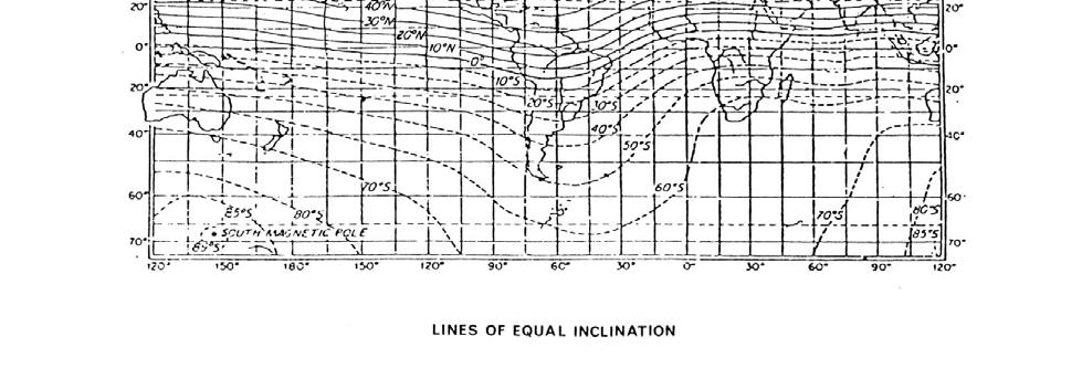
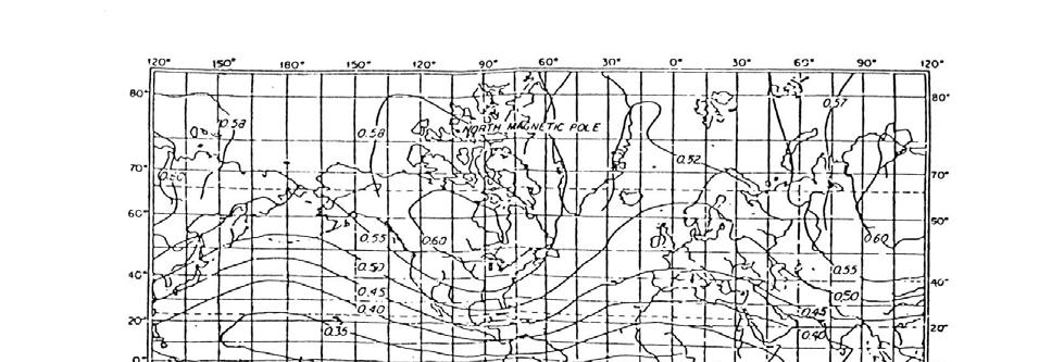
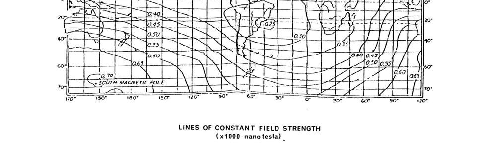
6 MAGNETIC ANOMALIES CAUSED BY FERROUS OBJECTS In order to understand how a magnetometer can locate a shipwreck it is necessary to consider what happens to the earth's magnetic field around a wreck or ferrous object. Consider the diagram shown in FIG 3, this shows how the lines of magnetic flux are distributed for a simple bar magnet. The spacing of these lines indicates the strength of the magnetic field at any point, and shows the field is stronger at the poles. When a ferrous object is placed in the magnetic field the lines of flux are distorted and become concentrated through the object. It is the ability of a material to concentrate the field which is termed its permeability. The object will also possess its own permanent magnetization and this results in a greater flux density around the object. The earth's magnetic field is similar to that of a bar magnet with the maximum strength at the poles (FIG 4). However, it is not an ideal bar magnet, but has variations in field strength due to certain geological effects. FIG 5 is a magnetic map showing the lines of constant field strength throughout the world. The change in magnetic field strength measured by a proton magnetometer is expressed in nanoteslas (nt) or gammas (lnt=lgamma). Around the UK the earth's magnetic field strength varies from approximately 47000nT in the south to 50000nT north of SCOTLAND. The lines of magnetic flux are not horizontal but inclined at 70 degrees. Although the earth's field varies by 3000nT over the UK it can be considered uniform over the area of search. The distortion caused to the earth's field by a steel wreck is shown in FIG 6a;this distortion is usually referred to as a magnetic anomaly. The associated graph (FIG 6b) shows the variation in field strength measured by the proton magnetometer as the probe is towed past a wreck. The detection distance used for the graph is the distance obtained by drawing a straight line between the probe and the wreck. The magnitude of the field disturbance is very small at the maximum detection range, while large variations exist close to the wreck. It is this large increase in the anomaly amplitude as the wreck is approached that enables the wreck to be homed onto, once an initial detection is made. The peak value of the magnetic anomaly depends on the mass of metal and the depth of water. FIG 7 shows the relationship between distance and the theoretical maximum anomaly amplitude that would be measured by the probe, for various ferrous objects. These maximum anomalies are estimated values and are only valid to within an order of magnitude, however the do give some idea of what to expect for different objects. While a steel wreck can cause magnetic anomalies extending to several hundred metres from the wreck site, smaller objects such as cannons, pipelines etc, cause more localised anomalies. The earth's magnetic field is unaffected by sand and mud and therefore the detection distances indicated above also apply equally to wrecks buried below the seabed
7 - 7 -

8 - 8 -
9 - 9 -
10 SETTING UP PROCEDURE The WRECKFINDER consists of two units, the probe which is towed behind the boat and the control box which remains in the boat. An additional 12-volt car or motorcycle battery is required to power the magnetometer and is connected to the control box via the power lead provided. Before the WRECKFINDER can be used to search a particular area the unit must be set up for maximum signal. The earth's magnetic field varies with geological position and therefore the magnetometer will require tuning for your area. Normally retuning is not necessary within a mile Radius of the initial tuning position. It is best to try setting up the magnetometer on land before attempting a search at sea. The following section describes the setting up procedure. The magnetometer can only be used to search for ferrous materials or compounds, and for this purpose it is extremely sensitive and has considerable range. This high sensitivity Co field variations means that the magnetometer may only be used remote from known earth field disturbers, such as power lines or buildings. Before attempting to set up the magnetometer ensure that it is positioned at least 100 yards from the nearest power line or building. Assuming the initial setting up is carried out on land the probe should be positioned about 20 feet from the electronics unit and battery. Initially position the probe so that it is pointing in approximately an east-west direction. Set the POLARISE control to 4 sec, the range to XI and the alarm to lont. Set the AREA TUNE control Co the letter for your area, as shown in Fig 8.Connect the power lead to a 12 volt battery (or 24 volt for the 24 volt model), red positive. You are now ready to switch on. The first thing you will notice is that the small meter needle will deflect across the scale every 4 seconds. Ad just the AREA TUNE control to one or two positions either side of your initial setting to obtain the maximum deflection on the small meter. The magnetometer is now set up for your area. If you now switch off, then on again the magnetometer will now set up on maximum signal level. When switched on the magnetometer makes three measurements and tests to see if they are correct for its locality; if so, it calibrates the magnetometer to the measured field strength and sets the large meter to centre scale. The field strength measured at calibration is stored in the microcomputer's memory and all subsequent measurements are compared with this value to determine the magnitude of any field disturbances. After each measurement the audible alarm will bleep if a valid measurement is made. This bleep indicates that the magnetometer is working correctly. If the magnetometer fails to Bleep when the alarm control is on then something is wrong i.e. low battery voltage etc. If now a ferrous object is gradually brought near to the probe the alarm will sound immediately the change in magnetic field strength exceeds the alarm setting. You should now understand the basic setting up procedure. It is not necessary to repeat this procedure each time you switch on provided you operate within 20 miles of your original setting up point. Just switch on and the magnetometer will automatically calibrate itself. The following two sections describe how to use the polarise and range controls to minimise the search time
11 - 11 -
12 POLARISE CONTROL A polarise time of 1,2,4 or 8 seconds can be selected by the front panel control. Increasing the polarise time gives a greater signal strength and therefore a greater deflection of the field strength meter. The greater signal level enables the magnetometer to make a more accurate measurement. Short polarise times are used when looking for small objects, as the boat travels a shorter distance between measurements, and is therefore more likely to be close Co the object when a measurement is made. RANGE CONTROL The range control can be set to either X1, X10, X100 or grad. The XI range is the most sensitive, with full scale deflection on the field strength meter corresponding Co +50 or -50 nt.xlo decreases the sensitivity to give a full scale deflection of +500 or -500 nt, and X100 reduces it by another factor of ten. Select the XI range initially as this is the most sensitive and is used while searching. Once a magnetic field anomaly is detected it may be necessary to select a lower sensitivity range in order Co measure the peak of the anomaly. Should a change in magnetic field strength exceed the range displayed on the meter the audible alarm will bleep to indicate this is so. When searching in areas containing magnetic rock the magnetic variation will cause the meter to deflect across the scale as the boat moves position. On the X1, X10 and X100 ranges the operator can re-position the meter to centre scale by switching the magnetometer off momentarily. This will cause the microcomputer to re-calibrate the magnetometer to the boats new position. However if the "grad position is selected on the range control the microcomputer attempts to cancel the effect of the gradual change in the magnetic field strength while still responding to localised changes caused by ferrous objects. It does this by only comparing the differences between any two successive readings. On making a measurement the microcomputer compares the field strength with the previous reading and displays the difference. It also saves the current reading as the new reference for comparison with the next reading. In this way only significant changes in the field strength are registered; the gradual change caused by the magnetic rock has little effect. However when searching for a steel wreck then the enormous change in the magnetic field caused by such a wreck will leave little doubt that a wreck has been detected. In areas with magnetic rocks the performance of a magnetometer is reduced as a greater change in the magnetic field is required before a positive detection is assumed. Even though the detection range is less in these areas it is still large enough to make the use of a magnetometer a considerable advantage over just an echo sounder
13 ALARM CONTROL The alarm control can be set to either OFF, 10,20 or 50nT. This feature enables a search to be made without the need to continually watch the meter. Each time the microcomputer makes a measurement it compares the change in field strength with the alarm setting, and sounds the alarm if it is greater. On the lower sensitivity ranges not all the alarm settings are possible. Table 1 shows the alarm value used by the computer for various settings. TABLE 1 RANGE ALARM SETTING XI X X100 NO ALARM Even if the alarm control is set to off the microcomputer will make the audible alarm bleep if a measurement is made which is greater than can be displayed on the meter. This bleep is a prompt to indicate when the range control should be adjusted
14 CONDUCTING A SEARCH During search operations the probe is towed behind the boat at sufficient distance to avoid detecting any metal on the boat itself. The probe can be towed at speeds up to 5 knots. Always pay out all of the cable as any cable left lying on the deck may get damaged. Take great care of the cable, as damage will result in malfunction of the magnetometer. A check should be made to determine if the probe is detecting metal fittings on the boat. Choose an area were there are no wrecks or ferrous objects. Steer the boat on a straight course with the magnetometer setup as described and in the "DETECT" position; there should be only a little variation of the field strength reading. The boat should now be turned to both port and starboard. If the probe is detecting the boat this will be seen as deflection on the meter as the boat turns. If this is greater than 10 or 15 nt then a longer cable is necessary. For small boats with outboard motors keep the tow cable away from the motor as this may induce ignition interference in the cable. If all is working well, the magnetometer should be giving only a single bleep, after each measurement is made. If the boat is now steered towards a wreck the number of bleeps will gradually increase as the wreck is approached. By observing the meter scale, the size of the maximum anomaly can be seen. This is a good indication of how near the wreck is; a typical example is a wreck of 1000 tons in 30 metres of water, should give a reading greater than 500nT when the probe is overhead. If you have not used a magnetometer before try detecting some known wrecks of different sizes to get a feeling for the type of response produced. For small ferrous objects try detecting marker buoys etc. CAUTION 1. THE X25 PROBE CONTAINS KEROSENE AND THIS MUST NOT BE ALLOWED TO FREEZE. 2. TAKE CARE TO AVOID FORMING SHARP BENDS IN THE TOW CABLE AS THIS CAN DAMAGE THE OUTER SHEATH. 3. ALWAYS USE A TOWROPE FOR SPEEDS IN EXCESS OF 5 KNOTS. 4. IN SOME CASES IT MAY BE DESIRABLE TO CONNECT THE MC3 INTO THE BOATS POWER SUPPLY. IN GENERAL THIS PRESENTS NO PROBLEMS AND THE POWER LEAD SHOULD BE FUSED WITH A 3 AMP FUSE. IF HOWEVER THE MAGNETOMETER MALFUNCTIONS AN IN LINE POWER FILTER (AVAILABLE FROM AQUASCAN) WILL BE REQUIRED. 5. THE MC3 USES WATERPROOF CONNECTORS TO CONNECT THE EXTERNAL POWER TO THE MAGNETOMETER ELECTRONICS UNIT. THE PLUG AND SOCKET WITHIN THE WATERPROOF CONNECTORS MUST BE KEPT DRY AT ALL TIMES. REPLACE THE PROTECTIVE CAPS IMMEDIATELY THE POWER LEAD-IS DISCONNECTED FROM THE ELECTRONICS UNIT
15 SEARCH TECHNIQUES HORIZONTAL DETECTION DISTANCE The single most important factor affecting the detectability of an object is the distance between the magnetometer probe and the object. With knowledge of the mass of ferrous material on the wreck site and the depth of water an approximate horizontal detection range can be determined. Using Fig 7 the maximum distance between the probe and the object that will just trigger the alarm can be found. For search purposes it is necessary to determine the horizontal component of this distance as this indicates how close the search vessel must pass by the wreck in order Co detect it. The horizontal detection range can either be determined mathematically or for those who have forgotten their school maths by a scale drawing. This horizontal distance is a good guide Co the width of each search lane as it allows for a certain amount of error in the initial estimates. SELECTING THE OPTIMUM CONTROL SETTINGS For a steel wreck a polarise time of at least 2 seconds is best as this gives a more accurate measurement and therefore a greater detection range. An alarm setting of lont and the range control set to the maximum sensitivity XI will give the optimum performance for the initial search. Once the wreck is detected it will be necessary to reduce the sensitivity of the magnetometer in order to home onto the exact location of the wreck. Switching to X10 reduces the sensitivity by a factor of ten. For large wrecks or ones close to the surface the X100 range may be necessary to determine the exact point when the probe is over the wreck. This ability to reduce the sensitivity is just one of the advantages the WRECKFINDER has over magnetometers which use the audio beat principle. For wrecks in very shallow water i.e. Less than 10 metres when the probe actually passes over the wreck no signal will be obtained from the magnetometer. This is not the magnetometer malfunctioning but is due to a very large magnetic gradient around the probe. This phenomena can be used to advantage with shallow water wrecks as it is a positive indication that ferrous metal is very close to the probe. The wreckfinder s built in microcomputer requires less than half a second to measure the earth's magnetic field strength, so very short polarise times can be used. This is another advantage of the WRECKFINDER over audio beat magnetometers which inherently require a long polarise time

16 - 16 -
17 A short polarise time of 1 second is used when searching for small objects such as iron cannon, anchors etc. This is because with small objects the magnetic anomaly is much more localised, so with a short polarise time the magnetometer probe travels a shorter distance between measurements and is therefore much more likely Co be making a measurement when near the object. Selecting the XI range and an alarm setting of lont ensures maximum sensitivity when searching for small objects. If the probe can be made to pass relatively close to the object then there will be a much greater chance of detection. One technique is to sink the probe by adding a weight to the cable just in front of the probe FIG 9.The depth the probe will run at is dependant on the size of weight, the length of cable and the speed of the boat. It is best to use long thin weights which will offer the minimum resistance to the water and must be made of a non-magnetic material, such as lead. If the probe cannot be made to run deep enough using weights a drift search should be used. The probe is suspended directly below the boat to the required depth and the boat drifts in the current. As both the boat and probe are influenced by the same current the probe remains directly below the boat. The probe should be suspended so that 1t is horizontal during the search. In areas containing magnetic rock the choice of the XI range may be inappropriate. FIG 10 shows the effect of a regional magnetic gradient caused by such rock. In the UK this type of rock is mainly found in north Wales and Scotland.1t's effect on the magnetometer when switched to XI range is to cause the field strength meter to gradually deflect across the scale as the boat moves position. The function of the microcomputer in the grad mode is described in section 4. This assumes that the probe is towed at a constant distance above the seabed and the seabed is relatively flat. If for instance there are rock formations which rise above the surrounding seabed, or the boat slows and the probe sinks closer to the seabed then the effect of the magnetic rock will be greater and will cause a deflection on the field strength meter. It is important to be aware of this type of effect as 1t can result in false optimism that a wreck has been located. The sensitivity on the "grad" range is the same as the XI range and the alarm trigger values are the same.1t may also be necessary in some magnetic areas to desensitize the alarm setting to avoid the alarm being triggered by the magnetic rock. CIRCULAR SEARCH FIG 11 shows a typical circular search pattern. This technique is very successful when trying to locate a steel wreck and involves the minimum equipment and time. An estimate of the wreck position is first made using either Decca coordinates or shore transits. A buoy should be dropped at this position as this gives a reference point Co work from. The boat should now be steered a few hundred metres from the buoy and the magnetometer switched on. Hopefully the magnetometer is away from the wreck site at this point and will calibrate itself to the ambient magnetic field strength. The boat should now be steered back to the buoy and a search pattern initiated as shown in FIG 11.If the wreck is in the area a reading will be obtain each time the boat is on the correct side of the buoy. Once the alarm is triggered drop a second buoy. From the position of the two buoys it will be obvious where the wreck lies. This will be confirmed by steering in the direction indicated; the magnetometer reading will be increasing with every measurement. Switch off the alarm as it has served its purpose and switch to the X10 range in order to pinpoint the exact position. The echo sounder can be used to verify that the wreck is standing clear of the seabed if required
18 PARALLEL SEARCH FIG 12 shows a parallel search pattern. This type of search is best done in the direction of the current as to attempt this type of search across the current is very difficult.a crude parallel search can be done with very few buoys when searching for a steel wreck as even if the parallel paths are not of equal width it is very unlikely the wreck will be missed. When searching for old wooden wrecks where the mass of ferrous material is considerably less than a steel wreck it is important that an accurate search pattern is followed so that areas can be confidently eliminated as the search progresses. In the open sea it is far easier to carry out an accurate parallel search than a circular search. By using buoys parallel lanes can be laid out so that any significant anomaly will be detected when the magnetometer is towed along the path. As each path is completed the buoys can be moved to the next area. Although this technique sounds easy it involves a great deal of planning if a comprehensive search is to be completed. It is also Extremely time consuming. SPEED The accuracy of the magnetic field strength measured by a proton magnetometer is unaffected by the speed of the boat. In some applications e.g. charter boats for diving and angling parties, of prime importance is the ability to locate wrecks quickly. These boats are mainly concerned with steel wrecks and in many cases the approximate position of the wreck is known. One technique that has proved very effective for this application is to mount the probe of the magnetometer on a boom, which extends out the bow of the boat. This has the advantage that the probe can just be attached to a pole on the foredeck and can be brought inboard when returning to harbour. There is also no cable to be trailed out each time the magnetometer is used and there is always the problem that the cable can snag the propeller. The magnetometer can then be a permanent fixture in the wheelhouse and is just switched on like other instruments. Mounting the probe on a boom is only suitable for nonferrous hulls and any ferrous fixings near the bow will influence the magnetic field measured by the magnetometer. This effect is seen as a deflection on the field strength meter as the boat turns. By careful positioning of the probe this effect can be limited to a few nanoteslas. When a typical peak anomaly, for a steel wreck of 1000 tons in 30 metres of water is 2000 nanotesla, the loss of a few nanotesla of sensitivity is out weighed by the advantage of a boom mounting. Using the magnetometer like this saves considerable time in pinpointing a wreck when compared to just using an echo sounder. Another great advantage of this type of installation is that the magnetometer can be continuously operated at any speed i.e. 20 knots without worrying about the cable
19 - 19 -
20 - 20 -
21 MANUFACTURER CONTACT INFORMATION If you should need to contact Aquascan International Limited for advice on your purchase, to order further equipment or to arrange a repair, please use the following contact information: - Mailing Address: Aquascan International Limited Aquascan House Hill Street Newport South Wales NP20 1LZ United Kingdom Tel: +44 (0) (0) Fax: +44 (0) Sales Enquiries: sales@aquascan.co.uk General Inquiries: info@aquascan.co.uk Technical Support: support@aquascan.co.uk Website:
DX-200 DIVER HELD. MAGNETOMETER... Operating Instructions...
 AQUASCAN INTERNATIONAL LTD. AQUASCAN HOUSE HILL STREET NEWPORT. SOUTH WALES. UK NP20 1LZ UNDERSEA DETECTION EQUIPMENT Tel: +44 1633 841117 Fax: +44 1633 254829 Email: info@aquascan.co.uk Website : www.aquascan.co.uk
INSTALLING THE ECHO SOUNDER TRANSDUCER CHANGING THE OPERATING CONFIGURATION
 INTRODUCTION INSTALLING THE DISPLAY INSTALLING THE LOG PADDLE WHEEL UNIT INSTALLING THE ECHO SOUNDER TRANSDUCER NOTES ON ELECTRICAL INTERFERENCE USING THE INSTRUMENT SETTING THE MINIMUM DEPTH ALARM SETTING
DESIGNED AND MANUFACTURED IN ENGLAND CLIPPER DEPTH DEPTH METRES ECHO SOUNDER.
 DESIGNED AND MANUFACTURED IN ENGLAND CLIPPER DEPTH DEPTH 7 METRES ECHO SOUNDER INTRODUCTION 2 INSTALLING THE DISPLAY 2 INSTALLING THE TRANSDUCER 3 NOTES ON ELECTRICAL INTERFERENCE 5 GETTING STARTED 5 OPERATIONAL
AQUAPULSE 1B UNDERWATER METAL DETECTOR
 AQUASCAN INTERNATIONAL LTD. AQUASCAN HOUSE HILL STREET NEWPORT. SOUTH WALES. UK NP20 1LZ UNDERSEA DETECTION EQUIPMENT Tel: +44 1633 841117/255645 Fax: +44 1633 254829 Email: info@aquascan.co.uk Website
Autopilot setup. VRF (Virtual Rudder Feedback) calibration. Software setup NSS evo2 Installation Manual
 calibration. Software setup NSS evo2 Installation Manual") Autopilot setup Verifying the autopilot connection When an AC12N, AC42N, or SG05 is connected to the NSS evo2 system, the NSS evo2 will automatically detect the autopilot and an Autopilot menu icon will
Autopilot setup Verifying the autopilot connection When an AC12N, AC42N, or SG05 is connected to the NSS evo2 system, the NSS evo2 will automatically detect the autopilot and an Autopilot menu icon will
Using a metal-detector to locate explosive hazards
 Using a metal-detector to locate explosive hazards There must always be absolute confidence in the metal-detector s ability to locate the target device at the required depth before metal-detector Clearance
frequently asked questions
 Hydra Pilot Fault Codes What do the fault codes for the Hydra Pilot mean? Fault Cause FAULT 100 FAULT 101 FAULT 102 FAULT 103 FAULT 104 FAULT 105 FAULT 106 FAULT 108 FAULT 109 FAULT 110 FAULT 111 FAULT
WIND CLIPPER KTS ILLUM SCALE INC DEC CLIPPER WIND SYSTEM
 CLIPPER WIND KTS ILLUM SCALE DEC INC CLIPPER WIND SYSTEM TABLE OF CONTENTS INTRODUCTION PRE-TEST OF INSTRUMENT INSTALLING THE MASTHEAD SENSOR UNIT INSTALLING THE DISPLAY NORMAL OPERATION CHANGING THE
Technical Data Sheet MF010-O-LC
 Technical Data Sheet MF010-O-LC - 1 - 1. Properties The oxygen measuring system MF010-O-LC determines the oxygen content in gas mixtures up to a temperature of 250 C. It is particularly suitable for the
Copyright 2004 by the Thomas G. Faria Corporation, Uncasville CT No part of this publication may by reproduced in any form, in an electronic
 Copyright 2004 by the Thomas G. Faria Corporation, Uncasville CT No part of this publication may by reproduced in any form, in an electronic retrieval system or otherwise, without the prior written permission
Installation, Compensation and Maintenance Instructions for. RITCHIE Compasses. Made In U.S.A
 Installation, Compensation and Maintenance Instructions for RITCHIE Compasses Made In U.S.A All Magnetic Compasses are vulnerable to magnetic interference, which will produce errors, called deviation.
DIVER MAG 1 MARINE MAGNETOMETER REV 709 OPERATION AND MAINTENANCE MANUAL
 DIVER MAG 1 MARINE MAGNETOMETER REV 709 OPERATION AND MAINTENANCE MANUAL 1 DIVER MAG 1 MARINE MAGNETOMETER OPERATION AND MAINTENANCE MANUAL 2 JW FISHERS MFG INC 1953 COUNTY ST. E. TAUNTON, MA 02718 USA
Instrumentation & Data Acquisition Systems
 Instrumentation & Data Acquisition Systems Section 3 -Level Robert W. Harrison, PE Bob@TheHarrisonHouse.com Made in USA 1 Level Section Question Which level measuring technology is the best solution when
OPERATIONS SEAFARER CERTIFICATION GUIDANCE NOTE SA MARITIME QUALIFICATIONS CODE. Deck: Chart Work
 Page 1 of 6 Compiled by Approved by Chief Examiner Syllabus Committee: 26 February 2013 OPERATIONS SEAFARER CERTIFICATION GUIDANCE NOTE SA MARITIME QUALIFICATIONS CODE Deck: Chart Work Page 2 of 6 COLUMN
ITTC Recommended Procedures and Guidelines
 Page 1 of 6 Table of Contents 1. PURPOSE...2 2. PARAMETERS...2 2.1 General Considerations...2 3 DESCRIPTION OF PROCEDURE...2 3.1 Model Design and Construction...2 3.2 Measurements...3 3.5 Execution of
MIE Medical Research Ltd Digital Analyser Pinch/Grip Instruction Manual
 Doc 116-03 Copyright 1998-2004 MIE Medical Research Ltd Getting Started MIE Medical Research Ltd Unpack your Digital Analyser and check that the following components are present: 1 x Digital Analyser
CONTROL and INSTRUMENTATION
 CONTROL and INSTRUMENTATION COURSE 500: 5 DAYS: Max 8 Candidates This course covers the key aspects of current instrumentation and process control technology and is designed to enable maintenance personnel
Constant Pressure Inlet (CCN) Operator Manual
 Operator Manual") Constant Pressure Inlet (CCN) Operator Manual DOC-0125 Revision J 2545 Central Avenue Boulder, CO 80301-5727 USA C O P Y R I G H T 2 0 1 1 D R O P L E T M E A S U R E M E N T T E C H N O L O G I E S, I
Constant Pressure Inlet (CCN) Operator Manual DOC-0125 Revision J 2545 Central Avenue Boulder, CO 80301-5727 USA C O P Y R I G H T 2 0 1 1 D R O P L E T M E A S U R E M E N T T E C H N O L O G I E S, I
LX Compass module 3 Electronic compass device User manual
 LX Compass module 3 Electronic compass device User manual LX navigation d.o.o., Tkalska 10 SLO 3000 Celje, tel: + 386 3 490 46 70, fax: + 386 3 490 46 71 info@lxnavigation.si, http://www.lxnavigation.com
Depth sensor. Product reference : REV 1. USER GUIDE and INSTALLATION GUIDE. nke Sailing competition
 Depth sensor Product reference : 90-60-456 REV 1 USER GUIDE and INSTALLATION GUIDE nke Sailing competition Z.I. Kerandré Rue Gutenberg 56700 HENNEBONT- FRANCE http://www.nke.fr After sale service n 33
AN31E Application Note
 Balancing Theory Aim of balancing How an unbalance evolves An unbalance exists when the principle mass axis of a rotating body, the so-called axis of inertia, does not coincide with the rotational axis.
Vibrating Wire Load Cell (3, 4, 5 And 6 Gauge Cells) User Manual
 User Manual") Vibrating Wire Load Cell (3, 4, 5 And 6 Gauge Cells) User Manual Man 188 1.1.0 06/08/2014 Chris Rasmussen Philip Day Chris Rasmussen Manual No. Revision Date Originator Checked Authorised for Issue User
Vibrating Wire Load Cell (3, 4, 5 And 6 Gauge Cells) User Manual Man 188 1.1.0 06/08/2014 Chris Rasmussen Philip Day Chris Rasmussen Manual No. Revision Date Originator Checked Authorised for Issue User
AN OFFSHORE TIDE GAUGE
 AN OFFSHORE TIDE GAUGE by Toshio Y a m a d a and Kinji I w a d a Hydrographic Department of Japan 1. INTRODUCTION Between October and December 1970 the Hydrographic Department of Japan carried out jointly
PIRANHA I & 2 OPERATION GUIDE
 PIRANHA I & 2 OPERATION GUIDE Thank You Thank you for purchasing a Piranha fishfinder from Humminbird, America s #1 Manufacturer of quality consumer marine electronics WARNING! This device should not be
Streamer Hydrophone Operation Manual
 Streamer Hydrophone Operation Manual Revision History Issue Change No. 1 1461 Reason for change Update manual with PMX561 MSDS and the removal of the DC561 MSDS. Manual document number revised (previously
Line Following with RobotC Page 1
 Line Following with RobotC Page 1 Line Following with By Michael David Lawton Introduction Line following is perhaps the best way available to VEX Robotics teams to quickly and reliably get to a certain
T EK-COR 1100A. Coriolis Mass Flowmeter. FLOW. Technology Solutions
 Technology Solutions T EK-COR 1100A Coriolis Mass Flowmeter FLOW www.tek-trol.com Flow Level Temperature Pressure Valves Analyzers Accessories TekValSys Introduction There can often be more than one type
Aquavar SOLO 2 Frequently Asked Questions
 Aquavar SOLO 2 Frequently Asked Questions How do I size the Aquavar SOLO 2 for the appropriate pump/motor combination? Can I use a 208 Volt motor? Can I run the Aquavar SOLO 2 up to 80HZ? What are the
Improving distillation tower operation
 Improving distillation tower operation Measuring differential pressure across long sections of distillation columns has always been challenging, but purpose-built sensor systems provide a solution Fast
REACTOR 40 MECHANICAL Configuration Guide
 REACTOR 40 MECHANICAL Configuration Guide Important Safety Information WARNING See the Important Safety and Product Information guide in the product box for product warnings and other important information.
ZIPWAKE DYNAMIC TRIM CONTROL SYSTEM OUTLINE OF OPERATING PRINCIPLES BEHIND THE AUTOMATIC MOTION CONTROL FEATURES
 ZIPWAKE DYNAMIC TRIM CONTROL SYSTEM OUTLINE OF OPERATING PRINCIPLES BEHIND THE AUTOMATIC MOTION CONTROL FEATURES TABLE OF CONTENTS 1 INTRODUCTION 3 2 SYSTEM COMPONENTS 3 3 PITCH AND ROLL ANGLES 4 4 AUTOMATIC
CLIPPER DEPTH METRES ENTER SHALL DEEP ILLUM CLIPPER ECHO SOUNDER
 CLIPPER DEPTH DEPTH DUET CLIPPER ECHO SOUNDER INTRODUCTION INSTALLING THE DISPLAY INSTALLING THE TRANSDUCER NOTES ON ELECTRICAL INTERFERENCE GETTING STARTED OPERATIONAL CONTROLS BACKLIGHT SETTING CHANGING
OPERATION AND INSTALLATION MANUAL
 AP46 Autopilot OPERATION AND INSTALLATION MANUAL www.tmq.com.au TMQ AP46 Autopilot Page 1 of 34 Ver1.0 07/03/2007 This page is Blank TMQ AP46 Autopilot Page 2 of 34 Ver1.0 07/03/2007 WARNING!...4 INTRODUCTION...5
CHEMICAL ENGINEERING LABORATORY CHEG 239W. Control of a Steam-Heated Mixing Tank with a Pneumatic Process Controller
 CHEMICAL ENGINEERING LABORATORY CHEG 239W Control of a Steam-Heated Mixing Tank with a Pneumatic Process Controller Objective The experiment involves tuning a commercial process controller for temperature
BLOCKAGE LOCATION THE PULSE METHOD
 BLOCKAGE LOCATION THE PULSE METHOD Presented by John Pitchford Pitchford In-Line Author James Pitchford ABSTRACT Pipeline blockages can result from a number of different mechanisms: wax or solid hydrates
Stevpris installation
 chaser Stevpris deployment for MODUs Introduction Typical methods for deployment and retrieval of Stevpris anchors with an anchor handling vessel (AHV) are described, focusing on the use of chasers for
Introduction. The Shearwater Petrel is an advanced technical diving computer for open and closed circuit divers.
 Introduction The Shearwater Petrel is an advanced technical diving computer for open and closed circuit divers. Although we strive to make the Petrel easy enough to use without reading the manual, please
PART 5 - OPTIONS CONTENTS 5.1 SYSTEM EXPANSION 5-3
 PART 5 - OPTIONS CONTENTS Para Page 5.1 SYSTEM EXPANSION 5-3 5.2 SENSORS 5-3 5.2.1 Trim Angle Sensor 5-3 5.2.2 Mast Rotation Sensor 5-3 5.2.3 Heel Angle Sensor 5-3 5.2.4 Barometric Pressure Sensor 5-3
Manual Leveling Control Installation/Operation
 ELECTROMECHANICAL TRIM TAB SYSTEMS Manual Leveling Control Installation/Operation Linear Devices Corporation dba Lectrotab 11126 Air Park Road, Suite G Ashland, VA 23005 www.lectrotab.com Phone: 804-368-8428
Best Practice Guide, Servomex 2700
 For full installations details refer to the. Best Practice Guide, Servomex 2700 Mounting: General Guidelines: Servomex 2700 Control Units and air supplies (utilities units) should, ideally, be mounted
3.6 Magnetic surveys. Sampling Time variations Gradiometers Processing. Sampling
 3.6 Magnetic surveys Sampling Time variations Gradiometers Processing Sampling Magnetic surveys can be taken along profiles or, more often, on a grid. The data for a grid is usually taken with fairly frequent
2600T Series Pressure Transmitters Plugged Impulse Line Detection Diagnostic. Pressure Measurement Engineered solutions for all applications
 Application Description AG/266PILD-EN Rev. C 2600T Series Pressure Transmitters Plugged Impulse Line Detection Diagnostic Pressure Measurement Engineered solutions for all applications Increase plant productivity
AQUAPULSE 1B-Compact UNDERWATER. METAL DETECTOR... Operating Instructions...
 AQUASCAN INTERNATIONAL LTD. AQUASCAN HOUSE HILL STREET NEWPORT. SOUTH WALES. UK NP20 1LZ UNDERSEA DETECTION EQUIPMENT Tel: +44 1633 841117 Fax: +44 1633 254829 Email: info@aquascan.co.uk Website : www.aquascan.co.uk
INTRODUCTION TO NETWORK WIND 3 MOUNTING THE UNIT 14 SELECTING THE DISPLAY MODE 5 ABBREVIATIONS AND DEFINITIONS 17
 CONTENTS CONTENTS 1 INSTALLATION 14 GENERAL INTRODUCTION TO B&G NETWORK 2 SITING THE UNIT 14 INTRODUCTION TO NETWORK WIND 3 MOUNTING THE UNIT 14 EXAMPLE SYSTEMS USING NETWORK WIND 4 SPECIFICATION 16 SELECTING
BOTTOM MAPPING WITH EM1002 /EM300 /TOPAS Calibration of the Simrad EM300 and EM1002 Multibeam Echo Sounders in the Langryggene calibration area.
 BOTTOM MAPPING WITH EM1002 /EM300 /TOPAS Calibration of the Simrad EM300 and EM1002 Multibeam Echo Sounders in the Langryggene calibration area. by Igor Kazantsev Haflidi Haflidason Asgeir Steinsland Introduction
Gravity wave effects on the calibration uncertainty of hydrometric current meters
 Gravity wave effects on the calibration uncertainty of hydrometric current meters Marc de Huu and Beat Wüthrich Federal Office of Metrology METAS, Switzerland E-mail: marc.dehuu@metas.ch Abstract Hydrometric
A4 Operation Manual. Fig.1-1 Controller Socket Diagram
 A4 Operation Manual Safety Instruction Please read this manual carefully, also with related manual for the machinery before use the controller. For installing and operating the controller properly and
Vibration and Pulsation Analysis and Solutions
 1 Vibration and Pulsation Analysis and Solutions Brian Howes, M.Sc., P.Eng. Beta Machinery Analysis Ltd. Problems created by excessive vibration in machinery can have serious economic impact. Frequently
OPERATION. Estimated kerf width compensation. HPR260 Manual Gas Instruction Manual 4-9
 Estimated kerf width compensation The widths in the chart below are for reference. Differences between installations and material composition may cause the specific user results to vary from those shown
General Accreditation Guidance. User checks and maintenance of laboratory balances
 General Accreditation Guidance User checks and maintenance of laboratory balances January 2018 Copyright National Association of Testing Authorities, Australia 2010 All intellectual property rights in
Owner s Manual. TreasureHound Depth Multiplier with EagleEye Pinpointing
 Owner s Manual TreasureHound Depth Multiplier with EagleEye Pinpointing Garrett TreasureHound with EagleEye Pinpointing Depth Multiplier Congratulations on your selection of the Garrett TreasureHound with
INSTALLATION INSTRUCTIONS
 INSTALLATION INSTRUCTIONS HIGH PRESSURE PUMP To minimize vibration, it is best to build brackets on the motor itself, similar to alternator brackets. Use cardboard to construct a pattern first before making
A NEW APPROACH TO BUCKLING DETECTION IN OFFSHORE PIPELINE LAYING
 A NEW APPROACH TO BUCKLING DETECTION IN OFFSHORE PIPELINE LAYING By Marian Copilet, Durham Pipeline Technology Ltd., Gateshead, UK & Prof. Ernie Appleton, University of Durham 1. ABSTRACT This paper discusses
ScanFish Katria. Intelligent wide-sweep ROTV for magnetometer surveys
 ScanFish Katria Intelligent wide-sweep ROTV for magnetometer surveys User-friendly control and monitoring software solution The ScanFish Katria comes with the ScanFish III Flight software, which is an
A4s Operation Manual
 A4s Operation Manual Safety Instruction Please read this manual carefully, also with related manual for the machinery before use the controller. For installing and operating the controller properly and
Owners Manual Release Date: Thursday, December 29, 2011
 S MFD/LRL Generators Page 1 Ground Current Generator GCG By Tim Williams Owners Manual Release Date: Thursday, December 29, 2011 This document is subjected to change without any notice. Please check the
SAFE CAPACITY TEST: INNOVATION AND SAVINGS
 SAFE CAPACITY TEST: INNOVATION AND SAVINGS TWO STAGE POWER DISTRIBUTION Summary Executive Summary 3 Traditional Load Bank Testing 3 The Safe Capacity Test: Innovation and Savings 4 Tradition vs Innovation
Cover Page for Lab Report Group Portion. Pump Performance
 Cover Page for Lab Report Group Portion Pump Performance Prepared by Professor J. M. Cimbala, Penn State University Latest revision: 02 March 2012 Name 1: Name 2: Name 3: [Name 4: ] Date: Section number:
Exercise 8. Closed-Loop Pressure Control, Proportional-Plus-Integral Mode EXERCISE OBJECTIVE
 Exercise 8 Closed-Loop Pressure Control, EXERCISE OBJECTIVE To understand open and closed-loop pressure control; To learn how to sense the pressure in a pneumatic circuit; To control the pressure in a
ZIRCONIA OXYGEN DETECTOR SERVICE MANUAL
 Service Manual ZIRCONIA OXYGEN DETECTOR SERVICE MANUAL TYPE: ZFK 3, 4, 7 TN5A08a-E CONTENTS. PREFACE.... MEASUREMENT PRINCIPLE... 3. ADJUSTMENT...3 3. Zero (Air) Adjustment... 3 3. Span Adjustment... 3
BUYER S GUIDE AQUAlogger 530WTD
 OCEAN & ENVIRONMENTAL BUYER S GUIDE AQUAlogger 530WTD Wireless Temperature and Depth Logger AQUAlogger 530WTD The AQUAlogger 530WTD has an innovative design that includes the ability to transfer stored
Product information. Capacitive. Level detection in liquid VEGACAP 62 VEGACAP 63 VEGACAP 64 VEGACAP 66 VEGACAP 69. Document ID: 29983
 Product information Level detection in liquid VEGACAP 62 VEGACAP 63 VEGACAP 64 VEGACAP 66 VEGACAP 69 Document ID: 29983 Contents Contents 1 Description of the measuring principle... 3 2 Type overview...
QPEO2/037N Credit Value: 15 QCF Level: 2 GLH: 68 Maintaining electrical equipment/systems
 Performing Engineering Operations QPEO2/037N Credit Value: 15 QCF Level: 2 GLH: 68 Maintaining electrical equipment/systems Learner Name: 2013 Excellence, Achievement & Learning Ltd EAL Assessment Route
One of the most important gauges on the panel is
 stick & rudder flight advisor Is Your Airspeed Indicator Honest? An accuracy how-to H.C. SKIP SMITH One of the most important gauges on the panel is the airspeed indicator. This is particularly true if
Design of a Microcontroller-Based Pitch Angle Controller for a Wind Powered Generator
 Journal of Engineering and Science Research 1 (2): 133-138, e-issn RMP Publications, DOI: Design of a Microcontroller-Based Pitch Angle Controller for a Wind Powered Generator Glenn V. Magwili, Michael
STRIP EDGE SHAPE CONTROL
 STRIP EDGE SHAPE CONTROL Gary Boulton, Tino Domanti, Terry Gerber, Glen Wallace Industrial Automation Services The control of shape in the strip edge region remains a significant challenge for shape control
RIPPLE TANK - with rippler & kit
 GENERAL DESCRIPTION: RIPPLE TANK - with rippler & kit Cat: SW3430-001 with illuminator, rippler & kit. The ripple tank is used to investigate wave motion in a shallow trough of water to understand how
Consistent terminology
 Appendix 1 - Appendix 2 Bye-Laws to Rules 35 to 37 - Courses Bye-Laws to the Rules of Racing - Courses 1. FISA Manual for Rowing Championships In addition to conforming to the Rules of Racing and to the
Maintaining electrical equipment/systems
 Unit 037 Maintaining electrical equipment/systems Level: 2 Credit value: 15 NDAQ number: 500/9514/6 Unit aim This unit covers the skills and knowledge needed to prove the competences required to cover
E2K-L. Liquid Level Sensor That Is Unaffected by the Color of the Pipe or Liquid. Liquid Level Sensor. Ordering Information
 Liquid Level EK-L CSM_EK-L_DS_E 3 Liquid Level That Is Unaffected by the Color of the or Liquid Mount to bypass pipes. Fit a wide range of pipe diameters: 8 to mm or to mm Built-in Amplifiers to save space.
Note that this arming distance is not affected by the speed setting of your torpedoes.
 Torpedoes From SilentHunterIII Community Manual Range The minimum (arming) range for the torpedoes in SH3 is officially stated as 300m. However, some [subsim.com (http://www.subsim.com)] forum members
TR Electronic Pressure Regulator. User s Manual
 TR Electronic Pressure Regulator Page 2 of 13 Table of Contents Warnings, Cautions & Notices... 3 Factory Default Setting... 4 Quick Start Procedure... 5 Configuration Tab... 8 Setup Tab... 9 Internal
DQM Annual Hopper QA Checks
 DQM Annual Hopper QA Checks The following document is intended to be a guide for conducting annual Dredge Quality Management quality assurance checks on hopper dredges. The procedures should provide general
EXPERIMENTAL MEASUREMENT OF THE WASH CHARACTERISTICS OF A FAST DISPLACEMENT CATAMARAN IN DEEP WATER
 EXPERIMENTAL MEASUREMENT OF THE WASH CHARACTERISTICS OF A FAST DISPLACEMENT CATAMARAN IN DEEP WATER A.F. Molland, P.A. Wilson and D.J. Taunton Ship Science Report No. 124 University of Southampton December
H&D Fitzgerald Pressure Pyknometry System Mark 5
 Setting the standard in density H&D Fitzgerald Pressure Pyknometry System Mark 5 Simple Portable Traceable Remember! Your density meter is only as good as its last calibration! A fundamental calibration
GUIDELINES FOR SURVEY OF OIL FLOATING STORAGE VESSELS FIXED AT ANCHORAGE
 GUIDANCE NOTES GD03-2017 CHINA CLASSIFICATION SOCIETY GUIDELINES FOR SURVEY OF OIL FLOATING STORAGE VESSELS FIXED AT ANCHORAGE 2017 Effective from 1 March 2017 BEIJING Chapter 1 GENERAL 1.1 Application
Coriolis Mass Flow Meter
 Coriolis Mass Flow Meter TMFW Series Mini Type Coriolis Mass Flow Meter Xi an Tosilon Automation Co., Ltd No.299, Daqing Rd, Lianhu District, Xi'an Shaanxi, China Tel: +86-29-8823 8550 info@tosilon.com;
HI 2314 HI 2315 HI 23151
 Instruction Manual HI 2314 HI 2315 HI 23151 Multi-Range Conductivity Meters for Laboratories www.hannainst.com Dear Customer, Thank you for choosing a Hanna Instruments product. Please read this instruction
Simrad yachting catalog 2007
 26 AUTOSTEERING Electronic intelligence combined with powerful and reliable designs make sure you enjoy boating even more. 27 Tillerpilots Enjoy silence when sailing SIMRAD TP SERIES REMOTE COMMANDER High
PROPORTIONING VALVE. Model 150 INSTRUCTION MANUAL. March 2017 IMS Company Stafford Road
 PROPORTIONING VALVE Model 150 INSTRUCTION MANUAL March 2017 IMS Company 10373 Stafford Road Telephone: (440) 543-1615 Fax: (440) 543-1069 Email: sales@imscompany.com 1 Introduction IMS Company reserves
Tips on Permanent Powered Fencing and Temporary Powered Fencing
 Tips on Permanent Powered Fencing and Temporary Powered Fencing The following outlines various simple, yet proven, methods in constructing both fixed and portable fencing systems as well as providing information
444C DUAL PERFORMANCE VALUE PACK
 (Chrome) PART NO. 44432 IMPORTANT: It is essential that you and any other operator of this product read and understand the contents of this manual before installing and using this product. SAVE THIS MANUAL
Ripple tank with LED light source. Ripple tank with LED light source, complete
 Ripple tank with LED light source Ripple tank with LED light source, complete 11260-02 11260-88 PHYWE Systeme GmbH & Co. KG Robert-Bosch-Breite 10 37079 Göttingen Germany Telefon +49 (0) 551 604 0 Fax
OWNER S MANUAL NMB SERIES
 OWNER S MANUAL NMB SERIES NMB Manual V2.0.doc 1. PARTS IDENTIFICATION LIST 1. 5. 2. 4. 3. 6(a). 6(b). Figure 1.1 1. Powerpack with timer option (x1) 2. Cell (x1) 3. Cell Housing (x1) 4. O-ring (x1) 5.
14/10/2013' Bathymetric Survey. egm502 seafloor mapping
 egm502 seafloor mapping lecture 10 single-beam echo-sounders Bathymetric Survey Bathymetry is the measurement of water depths - bathymetry is the underwater equivalent of terrestrial topography. A transect
Standard Practice for Eddy-Current Examination of Steel Tubular Products Using Magnetic Saturation 1
 Designation: E 309 95 An American National Standard Standard Practice for Eddy-Current Examination of Steel Tubular Products Using Magnetic Saturation 1 This standard is issued under the fixed designation
Best Practice for Calibrating LTH Conductivity Instruments
 Application Note Best Practice for Calibrating LTH Conductivity Instruments As accurate process measurement becomes an everyday requirement it is vital to be able to calibrate conductivity instruments
INSTALLATION PROCEDURE 1/4 & 1/8 MILE PERMANENT TRACK
 INSTALLATION PROCEDURE 1/4 & 1/8 MILE PERMANENT TRACK 1) Unpack all of the equipment and immediately inspect for shipping damage. Damages should be immediately reported to the carrier and noted on the
GHC 20. Owner s Manual
 GHC 20 Owner s Manual 2013 Garmin Ltd. or its subsidiaries All rights reserved. Under the copyright laws, this manual may not be copied, in whole or in part, without the written consent of Garmin. Garmin
DYNAMIC POSITIONING CONFERENCE October 7-8, New Applications. Dynamic Positioning for Heavy Lift Applications
 Return to Session Directory DYNAMIC POSITIONING CONFERENCE October 7-8, 2008 New Applications Dynamic Positioning for Heavy Lift Applications John Flint and Richard Stephens Converteam UK Ltd. (Rugby,
NIV EAU MATIC ST User Manual Made in Canada
 NIV EAU MATIC ST User Manual Made in Canada www.niveaumatic.com info@niveaumatic.com -2- Table of contents Introduction Section 1 Page 4 Installation Section 2 Pages 5 to 10 2.1 Control box 2.2 Sensor
Advanced Test Equipment Rentals ATEC (2832) OMS 600
 OMS 600") Established 1981 Advanced Test Equipment Rentals www.atecorp.com 800-404-ATEC (2832) OMS 600 Continuous partial discharge monitoring system for power generators and electrical motors Condition monitoring
Established 1981 Advanced Test Equipment Rentals www.atecorp.com 800-404-ATEC (2832) OMS 600 Continuous partial discharge monitoring system for power generators and electrical motors Condition monitoring
Certified Accuracy. Ring Force Gauge. Models and Capacities Available. Design and Principle of Operation
 Certified Accuracy Ring Force Gauge The accurate measurement of mechanical forces is required in hundreds of applications from a simple weighing procedure to the calibration of testing machines and load
Multiple Pressure Booster Systems With Variable Speed Controller Type BL
 Multiple Pressure Booster Systems With Variable Speed Controller Type BL General Characteristics - Single or multistage pumps - Horizontal or vertical mounting - Total head 30m ~ 250m - Material construction:
LYMPHA PRESS MANUFACTURED BY MEGO AFEK IMPORTED BY LYMPHA PRESS USA, Ltd. USERS MANUAL LYMPHA PRESS MODEL 201-M
 LYMPHA PRESS MANUFACTURED BY MEGO AFEK IMPORTED BY LYMPHA PRESS USA, Ltd. USERS MANUAL LYMPHA PRESS MODEL 201-M THE LYMPHA PRESS MODEL 201-M IS A THERAPEUTIC DEVICE FOR THE CONTROL OF LYMPHEDEMA OF THE
This guide relates to the CPN Series Chart Plotters CPN700i and CPN1010i
 This guide relates to the CPN Series Chart Plotters CPN700i and CPN1010i For older GPS Chart Plotters, the manual is available for download at www.standardhorizon.com or by contacting Marine Product Support
Radar, Ultrasonic and RF Level Transmitters
 Radar, Ultrasonic and RF Level Transmitters Both measures the time it takes the wave to travel between the transmitter and that reflected wave off the surface of the material to reach the transmitter again.
DRILL MONITOR DM-100 OPERATIONS MANUAL
 DRILL MONITOR DM-100 OPERATIONS MANUAL 1 INSTALLATION AND SETUP The Drill Monitor comes complete with the following parts: 1 Drill Monitor unit 1 Mounting bracket for Drill Monitor 1 Encoder 1 Encoder
Gas density monitor With integrated transmitter Model GDM-100-TI
 SF 6 gas solutions Gas density monitor With integrated transmitter Model GDM-100-TI grid Products WIKA data sheet SP 60.05 for further approvals see page 5 Applications Gas density monitoring of closed
Sontek RiverSurveyor Test Plan Prepared by David S. Mueller, OSW February 20, 2004
 Sontek RiverSurveyor Test Plan Prepared by David S. Mueller, OSW February 20, 2004 INTRODUCTION Sontek/YSI has introduced new firmware and software for their RiverSurveyor product line. Firmware changes