RULE THE MOUNTAIN. The Marker Team. PS: The current MARKER Technical Handbook is naturally also available in PDF form for download off the internet:
|
|
|
- Bertram Shelton
- 5 years ago
- Views:
Transcription

1 RULE THE MOUNTAIN We are very pleased to present you with the MARKER Technical Manual 2017/18. It is intended exclusively for our partners and for professionals in the field of ski bindings. The new handbook contains a wealth of insider information ranging from freeride, touring and novice bindings to pro-style rigs for alpine racing. It also includes a host of insider info, installation instructions, an extensive FAQ and a detailed overview of all MARKER bindings and their ideal uses. For over 60 years MARKER has stood for unbeatable performance and innovation. Our 2017/18 program once again delivers powerful and unique products to make the most beautiful sport in the world even safer and more attractive. As a specialized MARKER dealer, you are at the front lines of our interaction with end consumers. MARKER s pledges of quality and safety would not be seen or heard by the consumers without your conscientious work and professional recommendations. We'd like to take a moment to thank you for your remarkable efforts. Here s to a white and successful winter 2017/18! The Marker Team PS: The current MARKER Technical Handbook is naturally also available in PDF form for download off the internet: 1
2 CONTENT CONTENT 1 FOREWORD & GENERAL INFORMATION 1.1 Binding Component Description 2 GENERAL GUIDELINES 2.1 Binding Inspection 2.2 Ski Inspection 2.3 Boot Inspection 2.4 GRIPWALK 3 INSTALLATION - GENERAL GUIDELINES 3.1 Tools and Accessories 3.1 Installation Tools 3.2 Tools and their Application PAGE CONTENT 10 INSTALLATION MARKER / BLIZZARD SYSTEMS 10.1 Xcell Demo, TLX Demo, TCX Demo, TLT Demo & TP Demo 10.2 IQ TP 10.3 IQ Junior System INSTALLATION MARKER / MOVEMENT SYSTEMS FDT TP see 13.3 FDT TLT see 13.3 FREESKI TP 120 / TP 100 see 6.5 INSTALLATION MARKER / BOGNER - INDIGO SYSTEMS Xcell Demo FDT TP see 6.4 PAGE CONTENT 4 MARKER KINGPIN & KINGPIN DEMO 4.1 KINGPIN Component Description 4.2 KINGPIN 4.3 KINGPIN Demo 4.4 Information KINGPIN Adjustment 4.5 Replacing ski brake KINGPIN / gliding AFD 4.6 General Information for the skier - KINGPIN 4.7 Information KINGPIN skiing - mode / walking - mode 4.8 Crampons KINGPIN 5 INSTALLATION MARKER ROYAL FAMILY 5.1 MARKER Duke EPF 5.2 MARKER Jester Pro 5.3 MARKER Jester ID & Griffon ID & Squire ID 6 INSTALLATION MARKER BINDINGS & INSTALLATION UVO 6.1 MARKER F 10 Tour 6.2 MARKER F 12 Tour EPF 6.3 MARKER Race Xcell 6.4 Free Ten TPX & 11.0 TP Race 10 TCX & Race Race Junior 8 & Free Free 7 & 7.0 & Interfaces - general information 6.11 World Cup Piston Control Interface 6.12 Junior Race Interface MARKER UVO 6.14 Mounting positions MARKER UVO 6.15 Race Xcell Demo heel plate 7 INSTALLATION MARKER / VÖLKL SYSTEMS 7.1 rmotion2 GW 7.2 Wideride XL FR Demo GW & Wideride XL TCX Demo GW 7.3 VMotion GW 7.4 4Motion XL Demo VMotion Junior / VMotion Junior R see INSTALLATION MARKER / K 2 SYSTEMS 8.1 MXCELL TCx Demo 8.2 Quikclik models 8.3 M3 TCx light / M3 / ER3 TCx light & ER3 8.4 M2 / ERP BINDING ADJUSTMENT 11.1 Release Value Selection and Adjustment 11.2 Adjustment screws and scales 11.3 Function test and inspection 11.4 Trouble - shooting 12 SPECIAL CASES 12.1 Competition Bindings 12.2 Monoski 12.3 Adjustment outside of the standards 12.4 Antiquated bindings which do not conform the standard 12.5 Replacing ski brakes 12.6 Replacing ski brakes Inter Pivot, Squire & Tour heels 12.7 Replacing ski brakes Xcell, Race 10 & 8, 11.0 TC heels 12.8 Replacing ski brakes Compact Step - in heels 12.9 Installation DIN - Adapter AT - boot 13 MARKER RENTAL & DEMO MODELS 13.1 General Information and Descriptions 13.2 Installation Marker Jester Demo 13.3 Installation Marker Griffon D & Squire D & FDT models 13.4 Installation 10.0 Fastrak III & 10.0 Fastrak III TP 13.5 Installation Junior Fastrak II 13.6 Installation Junior RTL 13.7 Installation FDT Junior 13.8 Function Test and Service 14 INFORMATION FOR THE SKIER 14.1 Maintenance 14.2 Warranty 14.3 Service 14.4 Additional Information Marker Tour 14.5 Marker TOUR brakes & safety leash 14.6 Additional Information Marker Duke EPF & Baron EPF 14.7 Crampons 14.8 Crampons 15 APPENDIX 15.1 Screw Chart 15.2 Brake chart 15.3 Marker collection INSTALLATION MARKER / NORDICA SYSTEMS 9.1 N Power X EVO / N PRO X EVO / TPX EVO Nordica FDT models see
3 1.0 ABOUT THIS MANUAL FOREWORD This Technical Manual was designed from the user s point of view. It is clearly structured and easy to apply. The user has usually one product out of the MARKER Collection (binding, accessories, etc.) in front of him which he wants to install: The description for the product is easy to locate. The user receives complete installation instructions for the specific MARKER product. Each important installation step is described with text and an accompanying graphic. Important movements, groupings and views are presented. The pictures are a combination of photos and minimalized drawings. THIS LAYOUT RESULTS IN THE FOLLOWING ADVANTAGES: GENERAL INFORMATION All rights on this Technical Manual are owned by MARKER. Reproduction and reprinting of this manual, in whole or in part are permitted only with approval of MARKER and if the source of the information is specified. We reserve the right to make changes to the ski bindings and their accessories with respect to the information and illustrations contained in the manual. Technical status: MARKINGS AND SYMBOLS Important passages are emphasized in the text and it is essential to take note of them as follows: Requires measures to be taken during the installation to protect the skier s safety. 1.1 BINDING COMPONENT DESCRIPTION DUKE EPF + BARON EPF a JESTER ID + GRIFFON ID a 4 3 JESTER PRO 4 18 SQUIRE ID a a 1.1 BINDING COMPONENT DESCRIPTION 1) The user can actually see his MARKER product with all it s characteristics rather than imagining it. 2) Each working step, which may be valid only for this specific product, is clearly marked. 3) Detailed views are reduced to the essential in order to eliminate redundant distractions. MARKER, DUKE, BARON, JESTER, GRIFFON, GRIPWALK, KINGPIN, M, BIOMETRIC, BIOTECH, GLIDE, COMSHOCK, PISTON, EPS, SCHIZO, SQUIRE, LORD, XCELL, UVO and FASTRAK are registered MARKER VÖLKL (International) GmbH trademarks and other marks are pending. Emphasizes what has to be done or refrained from being done in order to avoid damaging the binding or valuable property during the installation process. Recommends action and gives instruction for smooth and quick installation. REFERENCES: References to other chapters are marked with an arrow, e.g.: MARKER TOUR + TOUR EPF a RACE XCELL a TOE 1 Release force adjustment screw 2 Toe cup (soleholder) 3 Gliding AFD 4 Release force scale HEEL 6 Brake pedal 7 Ski brake 8 Heel cup (soleholder) 9 Opening lever 10 Release force adjustment screw 11 Release force scale 12a Forward pressure adjustment screw MARKER TOUR + TOUR EPF 13 Tour system plate 14 Tour engagement lever 15 Tour climbing aide 16 Tour AFD adjustment screw JESTER PRO 17 AFD adjustment screw 18 Front plate 19 Heel plate DUKE EPF + BARON EPF 20 BCT plate 21 BCT engagement lever 22 Climbing aide 23 AFD adjustment screw RACE XCELL 24 Xcell shock absorber JESTER ID + GRIFFON ID + SQUIRE ID 18 Front plate 19 Heel plate 25 Adjustment screw gliding AFD sole.id 4 5
4 1.1 BINDING COMPONENT DESCRIPTION 1.1 BINDING COMPONENT DESCRIPTION 2.1 BINDING INSPECTION: 2.2 SKI INSPECTION: GENERAL NOTE: 9 9 RACE 10 TCX 11 RACE 10 + RACE JUNIOR 8 In order for Marker to optimize our quality management and product design it is requested that all Marker ski binding quality and product issues be reported to your Marker sales representative and / or 6 6 distributor. 1 FREE TEN TOE 1 Release force adjustment screw 2 Toe cup (soleholder) 3 Gliding AFD 4 Release force scale 5 BIOTECH upward release a a 11 FREE TEN 26 front plate EPS 27 heel plate a TPX / 11.0 TP / 7.0 / 7.0 FREE b 12 a a MARKER bindings conform to the CPSIA Act of 2008, Section 101 For complete information on Section 101 please refer to the CPSC or Marker web sites. As an authorized MARKER retailer you agree to check all the equipment according to DIN - ISO before the installation or adjustment of the function unit ski / ski binding / ski boot. If necessary, you have to replace one part of the unit or all three parts. All parts have to be in accordance with DIN - ISO standards. All new MARKER bindings are in accordance with the requirement of the national and international norms (ISO and ASTM) and may even have a higher accuracy than required. They are also inspected by the TÜV Product Service. Before the installation and adjustment perform a visual inspection of the binding (especially with used bindings). NOTE THE FOLLOWING: Check if the release force settings are correct according to the skier. Check the surfaces which stay in direct contact with the ski boot if they are deteriorated or damaged. Repair or replace the deteriorated or damaged parts with new parts. Check if the gliding AFD is damaged. Check if the ski brake is broken or bent, and check function. REPLACING SKI BRAKES BRAKE CHART 15.2 Check if screws are missing. Check if all screws have the correct length. SCREW CHART 15.1 Check scales for readability and adjustability. Remove dirt or corrosion with a moist rag or with compressed air. Repair damaged parts. Do not use solvents. Do not use silicone or any other lubricating agent on the toe and heel cup areas or any other binding part that has direct contact with the boot. Follow the ski manufacturer s instructions concerning drill bit dimensions, adhesives or tapping. In the absence of any ski manufacturer guideline, follow the recommendations in this chapter. Ensure adequate thickness to allow for proper screw penetration depth. If you suspect that the ski may be too thin, place the binding component on the ski so that the screw, about which you are concerned, hangs over the side of the ski. If it looks like the screw may dimple the ski base use a shorter MARKER screw or carefully grind the screw. Pay special attention when mounting junior skis. For the installation of the Free 8 and 7.0 / 4.5 bindings use the drill bits 3,6 x 7,5 or 4,1 x 7,5 for both junior skis and adult skis. The models Race 10 and Race Junior 8 will accomodate both junior skis and adult skis. When mounting these binding models on group 3 and 4 junior skis use the drill bits 3,6 x 7,5 or 4,1 x 7,5. Furthermore, the pre-installed screws have to be removed and replaced with the junior screw set. Ensure adequate width. Check the location of any top edges which the binding screws might contact and cause delamination or distortion. This is especially important for narrow skis with aluminum top edges. Check the location of the reinforced mounting platform or similar reinforcement plates which are 3 to 6 mm below the top surface. These plates must be drilled completely through to ensure proper screw penetration and retention and to help prevent top - sheet delamination caused by a screw tip not penetrating the mounting platform. When installed, the screws should not dimple or pierce the ski base. The intended use of MARKER ski bindings is only for the sport of alpine skiing and should not be used for any other purpose. 2.1 / 2.2 GENERAL GUIDELINES HEEL 6 Brake pedal 7 Ski brake 8 Heel cup (soleholder) 9 Opening lever 10 Release force adjustment screw 11 Release force scale 12a Forward pressure adjustment screw 12b Child & Junior forward pressure lever KINGPIN & KINGPIN DEMO: see 4.1 on page
5 2.3 GENERAL GUIDELINES 2.3 BOOT INSPECTION: Most modern alpine boots are manufactured in accordance with the ISO 5355 standard specification for ski boot dimensions, while most modern alpine touring boots are manufactured in accordance with ISO 9523 standard specification for alpine touring ski boot dimensions. These standards define the critical shapes at the toe and heel of the boot to help ensure compatibility with bindings, according to ISO 9462 and ISO CHECK THE BOOTS FOR THE FOLLOWING: If the boot is a standard boot, it will usually be stamped or marked with the initials DIN or ISO. If these initials are not on the boot, contact the boot manufacturer for approp riate procedures for modifying the boot in order to bring it within standard. If the boot can be modified so that the resulting boot meets the ISO standard, it can be used with MARKER bindings. Inspect the AFD area on the sole for damage, excessive wear or foreign material. This area of the sole should be smooth and flat. Check for excessive wear on any surface where the boot contacts the binding. The boot sole should not be worn beyond the minimum dimensions according to the norm. When in doubt, replace the boot. Inspect the boot for proper shell hardness. Although most boots are made with relatively hard plastics, some older models were made with low - grade thermoplastic material which can be easily depressed with a thumbnail. MARKER does not recommend the use of low - grade thermoplastic boots due to their inconsistent performance properties. If you determine that the boot is low - grade thermoplastic, make a note on the workshop ticket and inform the customer. Junior norm boots must never be used with adult bindings. The binding models Race Junior 8 and Free 8 are designed for use only with Junior norm boots type C. MARKER s 7.0 and 4.5 will accommodate both adult and junior boots. STANDARD BOOT NORMS: If the boot is a standard boot, it will usually be stamped or marked with the initials DIN or ISO. If these initials are not on the boot, contact the boot manufacturer for appropriate procedures for modifying the boot in order to bring it within standard. Only standard boots must be used. ISO 5355 boots are designed for use with a pair of classic skis and a standard alpine binding, and not with a monoski, snowboard or skiboard. ISO 9523 boots are designed for use with a pair of touring bindings, and not with alpine bindings, monoski, snowboard or skiboard. 2.3 BOOT INSPECTION STANDARD BOOT NORMS: Standard adult alpine boot according to DIN ISO 5355 (2.3-1) Standard children alpine boot according to DIN ISO 5355 (2.3-2) 19 ± 1 69 ± 2 5 ± ± ± ± ± 2 boot sole length L1 70 min. L 2 12 ± 2 boot sole length L1 4 ± 1 3 ± 1 69 ± 2 62 ± 2 7 ± 1 30 ± 1 8 ± ± L 1 < L min. 120 min. 7 ± 1 8 ± Adult boot type A Junior boot type C GENERAL GUIDELINES min. L 2 L 1 < 240 L 2 80 min. 90 min. Any performance or fit modification of a boot that could effect the function between the boot and binding should be inspected to verify that the boot meets Standard Alpine Boot and Standard Alpine Touring Boot Standards. Mechanical Inspection is recommended after any such modification. Only ski boots which are in accordance with the valid norm must be used in combination with a MARKER binding. MARKER KINGPIN and KINGPIN DEMO ski bindings are compatible with ski boots in accordance with DIN ISO 9523 with tech inserts to the Dynafit specification of In addition, some boot manufacturers have developed and manufactured their own inserts for their touring ski boots which should be suitable for Pin-Tech bindings. However, Marker cannot guarantee that these inserts will function correctly. Standard alpine touring boot according to DIN ISO 9523 (2.3-3) Touring boot 8 9


6 2.4 GRIPWALK 3.1 INSTALLATION - GENERAL GUIDELINES 2.4 GRIPWALK: In cooperation with well-known ski boot manufacturers MARKER presents a new boot binding system which provides increased comfort and better grip when walking, starting winter 16 / 17. The partners for the Gripwalk system are Dalbello, K2, Nordica, Tecnica and Fischer. The outsole set bears the product identification "Gripwalk " and is compatible with the following MARKER binding systems: - Alpine ski bindings in accordance with ISO standard 9462 with the additional marking "Gripwalk ". - Touring ski bindings in accordance with ISO standard Duke & Baron models - MARKER "sole.id" models IMPORTANT SAFETY ADVICE! The use of the Gripwalk outsoles with other binding systems than listed above can lead to the failure of the ski-boot-binding combination, impair the release function and is not allowed therefore. The Gripwalk outsoles are removable and must be replaced when worn and / or damaged. MARKER recommends as a matter of urgency, particularly before the skiing season and after any change of the outsoles to check the correct fit of the ski-boot-binding combination with suitable measuring equipment and, if required, to readjust the system. To label the fitted outsoles, we recommend affixing the enclosed Gripwalk sticker to the boot in a clearly visible location. IMPORTANT: Please note the information available at TOOLS AND ACCESSORIES: Art.nr.: MARKER silicone spray 300 ml Pozidriv screw driver # Hollow drill bit Helicoil insert PA 6 (100 pcs.) MARKER binding glue 100 ml Tap Screw driver slotted # Gauge drill Ø 8 mm (adjustable depth) Power bit 150 mm FEIN (Pozidriv ) Drill bit 4.1 x Drill bit 3.6 x Drill bit 3.6 x Plastic plugs 4.6; 100 ea. x 8 colors Allen key, ball end # 5 not shown: 2663 Drill bit UVO 2.1 x TOOLS AND ACCESSORIES: INSTALLATION - GENERAL GUIDELINES COMPATIBILITY BOOT TYPES / MARKER BINDUNG MODELS: BINDING BOOT ALPINE 5355 TOURING 9523 GRIPWALK WTR ALPINE X 11 GRIPWALK X X 12 TOURING / DUKE & BARON X X X X 14 SOLE.ID X X X X ALPINE 5355 GRIPWALK 10 11
7 3.1 INSTALLATION - GENERAL GUIDELINES 3.1 INSTALLATION TOOLS FOR MARKER BINDINGS: 3.1 INSTALLATION TOOLS FOR MARKER BINDINGS: W001G1T W006M1T W012J1T W001G1T ( mm) W012J1T ( mm) Jester 18 Pro, Jester 16 ID, Griffon 13 ID, Griffon 13, Squire 11 ID, Jester Demo, Race Xcell 24.0, 18.0, 16.0, Race Xcell 12.0, 12.0 TPX, 11.0 TP, 10.0 TP, 10.0, Free Ten, Free 8, Freeski TP, Race 10 TCX, Race 10, Race Junior 8 W006M1T ( mm) MARKER Duke EPF S & L MARKER Baron EPF S & L MARKER F 12 Tour EPF S & L 3.1 INSTALLATION - GENERAL GUIDELINES W010G1T W011J1T W010G1T ( mm) MARKER F 10 Tour S & L W011J1T ( mm) W003H1T W003H1T ( mm) Fastrak III FDT Junior S & L, 12 13


 MOUNTING THE TOOL ADAPTER: Remove the four standard feet and replace them with the")

8 3.1 INSTALLATION - GENERAL GUIDELINES 3.1 INSTALLATION TOOLS FOR MARKER BINDINGS: 3.1 INSTALLATION TOOLS FOR MARKER BINDINGS: W007H1T W002O1T W007H1T Free 7, 7.0, 4.5, 7.0 RTL, 4.5 RTL W002O1T ( mm) World Cup Piston Control, Junior Race Interface 2 For wide skis up to 148 mm MARKER offers an adapter kit for installation tools. (3.1-1) (mounting tool adapter wide skis 148 mm; Art. Nr.: W001J1A) MOUNTING THE TOOL ADAPTER: Remove the four standard feet and replace them with the mounting tool adapters as indicated in the picture (3.1-2). 3.1 INSTALLATION - GENERAL GUIDELINES W009P1T W009P1T ( mm) Jester Demo & Xcell Demo & FDT W004Q1T ( mm) (backview) W008R1T W008R1T ( mm) KINGPIN & KINGPIN Demo FOR BOTH SKI 14 15

: Twist the grips (1) until the clamping jaws (2) are fully extended. Position the installation tool on the ski and lock it by releasing the grips.")


9 3.2 INSTALLATION - GENERAL GUIDELINES 3.2 TOOLS AND THEIR APPLICATION: 3.2 TOOLS AND THEIR APPLICATION: ADJUSTMENT OF THE BINDING INSTALLATION TOOLS Use only original MARKER installation tools! Make sure that the installation tool is correctly positioned on the ski for all adjustments! The following installation steps are basic know - how and valid for all MARKER bindings. ADJUSTING BOOT SOLE LENGTH OPTIMIZED BY USING THE SKI BOOT (3.2-1): Twist the grips (1) until the clamping jaws (2) are fully extended. Position the installation tool on the ski and lock it by releasing the grips. Open the locking lever (3) and place the boot heel against the heel guide (5). Slide the toe guide (4) until the boot is firmly against both toe (4) and heel guide (5). Close the locking lever (3). Remove the ski boot. Ø 3,6 Ø 4,1 Ø 3,6 Ø 4, Drill bits for adult bindings ,5 9, Drill bits for child & junior bindings M 4.5 / M 7.0 7,5 7,5 GENERAL INFORMATION INSTALLATION DRILLING: Use original MARKER drill bits for an optimal result (3.2-7). Drill all necessary mounting holes through the drill bushings on the installation tool. (Details: see installation of the individual bindings) After drilling is completed remove the installation tool from the ski. Always keep the drill bit vertically aligned with the drill bushings in the installation tool and drill to the countersunk depth. (3.2-8) Shavings and dust have to be removed from the surface of the ski and all holes. 3.2 INSTALLATION - GENERAL GUIDELINES WITHOUT SKI BOOT (3.2-2): TAPPING: Ask for the boot sole length or size of the ski boot (marked on the boot or measure it). Adjust the gauge of the sole length on scale (6) or (7). Close the locking lever (3). Holes should only be tapped if recommended by the ski manufacturer. Use an original MARKER tap. Use the installation tool for tapping DETERMINE THE BINDING PLACEMENT ON THE SKI IF MID - SOLE MARKS ON THE SKIS ARE USED: Place the installation tool on the ski and align the mid - sole mark on the ski with the mid - sole mark on the installation tool (3.2-3) Drill all mounting holes. Tap through the drill bushings of the installation tool. Apply slight downward pressure and turn the tap. As soon as the tap begins to cut, simple turning will thread the hole. Turn the tap three or four revolutions. (3.2-9) IF BOOT TOE MARKS ON THE SKIS ARE USED: Place the installation tool on the ski and align the toe guide on the tool with the boot toe mark on the ski (3.2-4). 3 4 U > 4 U Be careful not to tap too deep! Back the tap out of the hole. Shavings and dust have to be removed from the surface of the ski and all holes. Before drilling, check that the installation tool is flush and centered on the ski (3.2-5)! Take particular care with skis that have angled sidewalls, extreme sidecuts or external plates

10 3.2 INSTALLATION - GENERAL GUIDELINES 3.2 TOOLS AND THEIR APPLICATION: ATTACHMENT SCREWS: Use only original MARKER attachment screws. All screws must be firmly seated and not stripped. If a power driver is used, keep the torque settings on the clutch as low as possible to help prevent stripping of the screws. Final tightening of the screws must always be done by hand. The screw head should be flush with the binding and the binding should be firmly attached to the ski. Check that each screw is firmly seated. For supply or to check for the correct screws use the SCREW CHARTS 15.1 STRIPPED SCREWS: Occasionally a screw will be over - torqued or the hole stripped. Repair using: MARKER hollow drill bit (Part No. 2651) MARKER helicoil insert (Part No. 2653) Remove all binding parts from the ski. Place the proper installation tool over the stripped holes to use the appropriate drill bushing to repair the stripped screw. Slowly drill through the bushing until the hollow drill bit step stops on the top of the bushing (3.2-10). Remove the installation tool. Shavings and dust have to be removed from the surface of the ski and all holes. Strike the base with your hand to remove any shavings. Using a hammer, plug the hole with the MARKER plastic insert (3.2-11). 4.1 MARKER KINGPIN BINDING COMPONENTS INSTALLATION OF MARKER KINGPIN BINDINGS 4 2 Make sure that the plastic insert is flush with the top - sheet of the ski (3.2-12)! Re - install the binding. Insert the binding screws and tighten only by hand! MARKER KINGPIN & KINGPIN DEMO BINDING COMPONENTS: 1 - Opening lever toe 2 - Soleholder toe 3 - Pin-Tech toe retaining pins 4 - Step-in aids toe 5 - Crampon holder 6 - Change-over lever for ascent mode 7 - Opening lever heel 8 - Indicator scale heel vertical release 9 - Indicator scale twist release 10 - Heel housing 11 - Hiking aids 1 and Brake pedal 13 - Brake arm 14 - XXL-Power transmitter 15 - Demo length adjustment lever 16 - Demo front plate with length scale MARKER KINGPIN and KINGPIN DEMO ski bindings are compatible with ski boots in accordance with DIN ISO 9523 with tech inserts to the Dynafit specification of In addition, some boot manufacturers have developed and manufactured their own inserts for their touring ski boots which should be suitable for Pin-Tech bindings. However, Marker cannot guarantee that these inserts will function correctly. Boots that do not support the settings described in this Marker technical manual (chapter ) should not be used with Marker Pin-Tech bindings! 18 19


 Screw the heel onto the heel plate by hand! (4.")


11 4.2 INSTALLATION OF MARKER KINGPIN BINDINGS 4.2 INSTALLATION OF MARKER KINGPIN BINDINGS 4.2 INSTALLATION OF MARKER KINGPIN BINDINGS toe heel DRILLING THE ATTACHMENT HOLES: sole length mm mm tool length settings 270 mm 375 mm Place the MARKER KINGPIN installation tool W008R1T (or installation tool W008P1T + sticker A ) in the correct position on the ski. (4.2-1) Drill 4 holes for the toe through the front black drill bushings. Drill 5 holes for the heel plate through the rear drill bushings. Remove the installation tool from the ski With strong pressure, screw the heel forward onto the plate by turning the forward pressure adjustment screw. (4.2-5) Screw the heel onto the heel plate by hand! (4.2-6) Open the toe by pressing down the toe opening lever. (4.2-7) 4.2 INSTALLATION OF MARKER KINGPIN BINDINGS SKI TIP See DRILLING INSTRUCTIONS 3.2 INSTALLING THE TOE: Install the toe with the pre - installed screws in the front holes. Tighten the screws lightly, then firmly. (4.2-2) INSTALLING THE HEEL PLATE: Switch the change-over lever 180 forward. (4.2-8) Install the heel plate with the pre - installed screws in the rear holes. Tighten the screws lightly, then firmly. (4.2-3) INSTALLING THE HEEL: Slide the heel from the rear of the plate forward until it stops. (4.2-4) Open the heel. (4.2-9) 20 21


 4.2-14 4.")

 2-12 4.")


12 4.2 INSTALLATION OF MARKER KINGPIN BINDINGS 4.2 INSTALLATION OF MARKER KINGPIN BINDINGS 4.2 INSTALLATION OF MARKER KINGPIN BINDINGS Position the tip of the ski boot between the Pin-Tech retaining pins on the toe. Then press the tip of the boot down and step into the toe. (4.2-10) The pins must be locked fully into position in the insert, the toe opening lever has to snap to the "Ski" position. (4.2-11) Remove the ski boot, then re - insert it into the binding and recheck the adjustment. IMPORTANT SAFETY ADVICE! Make sure that you do not exceed the»stop«marking on the plate when adjusting the sole length backward! (4.2-15) 4.2 INSTALLATION OF MARKER KINGPIN BINDINGS POSITIONING THE HEEL: Place the ski boot into the binding and turn the adjustment screw until the position of the heel is approximately right. (4.2-12) After altering the binding, visually inspect the spacing between the boot sole and the change-over lever: the sole may not touch the lever after stepping in! ( ) CHECK FORWARD PRESSURE: Place the ski boot into the binding and close it. Check if the forward pressure adjustment screw is flush with the back of the heel housing. If this adjustment is incorrect, turn the screw until it is flush with the back of the housing. ( and ) INFORMATION FOR BINDING ADJUSTMENT: see chapter


 INSTALLING THE HEEL: Slide the heel from the rear of the plate forward until it stops. (4.3-7) 4.")
 in")

 A See DRILLING INSTRUCTIONS 3.2 4.")

13 4.3 INSTALLATION OF MARKER KINGPIN BINDINGS 4.3 INSTALLATION OF MARKER KINGPIN DEMO BINDINGS 4.3 INSTALLATION OF MARKER KINGPIN DEMO BINDINGS toe heel DRILLING THE ATTACHMENT HOLES: Adjusting the installation tool: the arrow "Demo" on the front drill plate must be aligned with the marking "Demo" on the frame Close the locking lever. (4.3-5) Ensure that the lever is engaged properly! INSTALLING THE HEEL PLATE: Install the heel plate with the pre - installed screws in the rear holes. Tighten the screws lightly, then firmly. (4.3-6) INSTALLING THE HEEL: Slide the heel from the rear of the plate forward until it stops. (4.3-7) 4.3 INSTALLATION OF MARKER KINGPIN BINDINGS ski tip Place the MARKER KINGPIN installation tool W008R1T (or installation tool W008P1T + sticker A ) in the correct position on the ski. (4.3-1) Drill 4 holes for the toe through the front silver drill bushings. Drill 5 holes for the heel plate through the rear drill bushings. Remove the installation tool from the ski With strong pressure, screw the heel forward onto the plate by turning the forward pressure adjustment screw. (4.3-8) A See DRILLING INSTRUCTIONS Screw the heel onto the heel plate by hand! B C INSTALLING THE TOE PLATE: Place the toe plate onto the ski. Insert the enclosed screws. Tighten the screws lightly, then firmly. (4.3-2) Open the toe by pressing down the toe opening lever. (4.3-9) Ls INSTALLING THE TOE: Press down the lever lock and open the lever. Slide the toe with lever open from the front of the plate backward. (4.3-3) Switch the change-over lever 180 forward. (4.3-10) Slide the toe backward to the correct sole length in accordance with the sole length scale. (4.3-4) 24 25

 Position the tip of the ski boot between the Pin-Tech retaining pins on the")
 The pins must be locked fully into position in the insert, the toe opening")


 Remove the ski boot, then re - insert it into the binding and recheck the")


 After altering the binding, visually inspect the spacing between the boot")
14 4.3 INSTALLATION OF MARKER KINGPIN BINDINGS 4.3 INSTALLATION OF MARKER KINGPIN DEMO BINDINGS 4.3 INSTALLATION OF MARKER KINGPIN DEMO BINDINGS Open the heel. (4.3-11) Position the tip of the ski boot between the Pin-Tech retaining pins on the toe. Then press the tip of the boot down and step into the toe. (4.3-12) The pins must be locked fully into position in the insert, the toe opening lever has to snap to the "Ski" position. (4.3-13) Correct forward pressure: Check if the forward pressure adjustment screw is flush with the back of the heel housing. If this adjustment is incorrect, turn the screw until it is flush with the back of the housing. ( and ) Remove the ski boot, then re - insert it into the binding and recheck the adjustment. IMPORTANT SAFETY ADVICE! Make sure that you do not exceed the»stop«marking on the plate when adjusting the sole length backward! (4.3-18) 4.3 INSTALLATION OF MARKER KINGPIN BINDINGS POSITIONING THE HEEL: Place the ski boot into the binding and turn the adjustment screw until the position of the heel is approximately right. (4.3-14) After altering the binding, visually inspect the spacing between the boot sole and the change-over lever: the sole may not touch the lever after stepping in! ( and ) CHECK FORWARD PRESSURE: Place the ski boot into the binding and close it. (4.3-15) INFORMATION FOR BINDING ADJUSTMENT: see chapter

 Turn the adjustment screw (1) until the indicator line aligns with the selected release setting on the indicator scale (2). (4.4-2) LATERAL RELEASE (4.")
 until the indicator line aligns with the selected release setting on the indicator scale (4)")

 and calibration equipment that initiates a trigger via a lever arm to which force is applied (e.g. Wintersteiger, Sportech, etc.")
 For equipment that initiates a trigger via a lever arm to which force is applied, the ski has to be inserted the other way round.")


15 4.4 MARKER KINGPIN - INFORMATION FOR BINDING ADJUSTMENT 4.4 MARKER KINGPIN - INFORMATION FOR BINDING ADJUSTMENT 4.4 MARKER KINGPIN - INFORMATION FOR BINDING ADJUSTMENT BINDING RELEASE FORCE ADJUSTMENT SCREWS AND RELEASE VALUE INDICATOR SCALES MARKER recommends adjustment with a Pozidriv 3 screwdriver. ADJUSTMENT SCREWS AND INDICATOR SCALES ON THE HEEL VERTICAL RELEASE (4.4-1) Turn the adjustment screw (1) until the indicator line aligns with the selected release setting on the indicator scale (2). (4.4-2) LATERAL RELEASE (4.4-3) To adjust the lateral release value fold down both hiking aids. Turn the adjustment screw (3) until the indicator line aligns with the selected release setting on the indicator scale (4). (4.4-4) FUNCTION TEST AND SERVICE KINGPIN bindings can be tested without restrictions on and with standard setting and calibration equipment Laser 4 cm 0 7 cm For all MARKER KINGPIN models, a distinction must be made between calibration equipment and tools that work purely based on torque (e.g. Montana, Vermont Calibrator etc.) and calibration equipment that initiates a trigger via a lever arm to which force is applied (e.g. Wintersteiger, Sportech, etc.). The process for equipment that works purely based on torque is as usual. (4.4-5) For equipment that initiates a trigger via a lever arm to which force is applied, the ski has to be inserted the other way round. (The tip of the ski points in the opposite direction to normal). (4.4-6) The procedure is then identical to the procedure for all other Marker bindings. If you have any further questions on checking the binding with setting tools, please contact the Marker sales department or the manufacturer of the setting tool. When mounting the binding make sure that you fit the enclosed stickers to the ski. (4.4-7) 4.4 MARKER KINGPIN - INFORMATION FOR BINDING ADJUSTMENT RELEASE VALUE SELECTION AND ADJUSTMENT: Following the correct adjustment for sole length and forward pressure, the release value has to be selected and adjusted. Use the weight method to match the individual skier s needs. See RELEASE VALUE SELECTION AND ADJUSTMENT: BINDING ADJUSTMENT KINGPIN DEMO: see chapter The release value selection and adjustment has to be done very accurately to care for the skier s safety. All key information including the release value must be recorded in the workorder The enclosed info booklet must be handed over to the customer. (4.4-8) 28 29


 Remove the attachment screws of the ski brake. (4.")
 4.5-7 4.")

 Install the attachment screws and tighten them by hand.")


 4.")

 IMPORTANT SAFETY ADVICE!")

16 4.5 MARKER KINGPIN REPLACING BRAKES / GLIDING AFD 4.5 MARKER KINGPIN REPLACING BRAKES / INSTALLATION OF GLIDING AFD 4.5 MARKER KINGPIN REPLACING BRAKES / INSTALLATION OF GLIDING AFD DEMOUNT THE SKI BRAKE: Switch the change-over lever 180 forward to the "Ski" position. (4.5-1) Remove the attachment screws of the ski brake. (4.5-2) Pull the ski brake slightly forward and upward to remove. (4.5-3) Sliding the ski brake backward, make sure that the hooks of the brake base latch beneath the metal base plate and the plastic base plate of the heel on both sides! (4.5-7) Install the attachment screws and tighten them by hand. (4.5-8) INSTALLATION OF THE KINGPIN GLIDING AFD: The brakes of the KINGPIN bindings can be replaced by the AFD gliding platform. When using the binding MARKER KINGPIN without brake a safety leash must be installed! Remove the brake as described under 4.5-1, and Mount the gliding AFD from top to the heel plate, ensure that the screw points align with the drilled holes. (4.5-9) Install the attachment screws and tighten them by hand. (4.5-10) 4.5 MARKER KINGPIN REPLACING BRAKES / GLIDING AFD INSTALL THE KINGPIN BRAKE: Mount the brake from top to the heel plate. (4.5-4) IMPORTANT SAFETY ADVICE! The MARKER KINGPIN must be equipped with ski brake and / or safety leash! In case of disregard the ski can speed downhill after a release and hazard other persons. Slide the brake backward onto the heel plate. (4.5-5 and 4.5-6) MARKER offers a special KINGPIN safety leash. (4.5-11) Art. #: L001P1A ATTACHING THE SAFETY LEASH: Pass the leash through the hole on the right side of the toe and secure the leash with a cow-hitch. (4.5-12)


17 4.6 MARKER KINGPIN - INFORMATION FOR THE SKIER 4.6 MARKER KINGPIN - INFORMATION FOR THE SKIER 4.7 MARKER KINGPIN - INFORMATION FOR THE SKIER In addition to the system explanations of page 146, the following instructions must be given to the intended user of a MARKER KINGPIN binding: STEP - IN: Clear snow, ice and dirt from the sole of the ski boot and the Pin- Tech inserts before stepping into the binding. If the heel sole holder is closed, open it by pressing the opening lever with the ski pole tip, boot sole, ski tail or hand. If the toe is closed, open it by pressing down the toe opening lever. Position the tip of the ski boot on the toe's step-in aids and between the Pin-Tech retaining pins on the toe. Then press the tip of the boot down and step into the toe until the pins are locked fully into position in the insert. Move the locked boot back and forth several times to ensure that boot and binding are securely connected. Close the binding by stepping straight down into the heel. STEP - OUT: Variant 1: Press down the opening lever on the toe with a ski pole, ski, ski boot or by hand. Lift the tip of the ski boot slightly and rotate the boot sideways out of the binding. Before you can step in again, the heel must be opened. Variant 2: Press down the opening lever on the heel with a ski pole, ski, ski boot or by hand. Lift the heel of the ski boot slightly and press down the opening lever on the toe with a ski pole, ski or your hand. OPENING THE BINDING AFTER A FALL OR ACCIDENT: Press down the opening levers (heel and / or toe) with a ski pole or by hand. SYSTEM EXPLANATION FOR THE SKIER: Explain the boot - to - binding adjustment. Show where the release adjustment screws are and explain the adjustment at the visual indicators on the ski bindings and how they correspond to the recorded numbers on the workshop form. The skier should know his own DIN settings and / or skier code. Point out the left and the right ski indicators. If any system components are worn out of standard or otherwise unsuitable for continued use, the skier must be clearly informed of the problem and warned that continued use may significantly increase his or her risk of injury. Advise that if any problem develops with any part of the function unit ski / ski binding / ski boot it should be brought to a MARKER authorized retailer for inspection and service. RECEIPT OF IN - BOX INSTRUCTIONS: Whenever a new ski binding is delivered to the skier she or he should receive the in - box instructions and the warranty information. The enclosed info booklet must be handed over to the customer. MAINTENANCE: Explain to the skier that the ski binding should be kept clean and free of dirt, rust, salt or other contaminants. Recommend that the complete function unit ski / ski binding / ski boot has to be brought to a MARKER authorized retailer for inspection prior to the beginning of each ski season. SKIER SIGNATURE The skier must read, understand and agree to the conditions specified in the workshop form and / or any release agreement. Make sure that the skier signs the workshop form and /or the release agreement. If the skier is a minor, this document should be signed by a parent or a legal guardian. A copy of the signed documents has to be handed to the customer. The skier should understand that there are inherent and other risks in the sport of skiing. Explain that the ski binding will not release under all circumstances nor is it possible to predict every situation in which it will release and is, therefore, no guarantee of his or her safety. Explain to the skier that touring ski bindings are suitable only for the purpose they are intended for and therewith restrictions are related II I In addition to the system explanations of page 146, the following instructions must be given to the intended user of a MARKER KINGPIN binding: CHANGE - OVER FROM SKIING TO HIKING POSITION: An adjusting lever between the toe and heel can be used to set two different positions (skiing - mode / walking - mode). There is also another lever at the front end of the toe (C). that can also be used to choose between the positions for descent (SKI) and ascent (WALK). To switch from the descent position to ascent mode in order to walk with the binding, move the adjusting lever (4.7-1, and 4.7-3) backwards by 180 and pull the toe opening lever upwards (4.7-4). The lever noticeably clicks into a catch and should be pushed as far as possible. When taking the first step with the binding in walking mode, the brake is automatically applied and the heel clicks, thus getting the hiking aids ready for use. The ski mountaineer is now in the 0 walking position. USING THE HIKING AID In hiking mode, you can use two hiking aids with different angles. (4.7-5) HIKING AID LOW POSITION: To use this position, fold down hiking aid 1 with the pole disc or by brushing along the heel opening lever with the tip of the pole. (4.7-6) HIKING AID HIGH POSITION: To use this position, fold down the hiking aid 2 with the pole disc or by brushing along the heel opening lever with the tip of the pole. (4.7-7) 4.7 MARKER KINGPIN - INFORMATION FOR THE SKIER HIKING AID BASIC POSITION: Fold the hiking aids back into the starting position individually or together with the pole disc, or by brushing along the heel opening lever with the tip of the pole


 to the skiing - mode")


 Art.-Nr.")

 The crampon must noticeably click in place when it is centered. (4.")


18 4.7 MARKER KINGPIN - INFORMATION FOR THE SKIER 4.7 MARKER KINGPIN - INFORMATION FOR THE SKIER 4.8 MARKER KINGPIN - INFORMATION FOR THE SKIER CHANGING FROM WALKING - MODE TO SKIING - MODE: Free the bindings from snow and ice before changing from the walking - mode to the skiing - mode! In order to change from the walking - mode (unlocked position) to the skiing - mode (locked position) switch the lever 180 forward. (4.7-8, and ). Because the brake is not active in ascent mode, the lever must be set to the descent position before the skins are removed from the ski KINGPIN CRAMPONS: MARKER offers special crampons for the MARKER KINGPIN: (4.8-1) Crampons KINGPIN 90 mm (for ski width mm) Art.-Nr. H001P1P Crampons KINGPIN 105 mm (for ski width mm) Art.-Nr. H002P1P Crampons KINGPIN 120 mm (for ski width mm) Art.-Nr. H003P1P ATTACHING THE CRAMPONS: Insert the crampon with the axis into the recess provided at the toe. Tilt the crampon around 60 to insert. (4.8-2 and 4.8-3) The crampon must noticeably click in place when it is centered. (4.8-4) Using crampons that are too small can damage the ski! 4.8 MARKER KINGPIN - INFORMATION FOR THE SKIER No hiking aid may be used when walking with crampons. The effective action of the crampon in the snow may otherwise be too small. DETACHING THE CRAMPONS: For downhill skiing, always make sure that the opening lever toe (at the front end of the toe) is in the flat skiing position. The binding should always be in downhill mode (SKI) when skiing! (4.7-11) Tilt the crampon around 60. (4.8-5) Push against the crampon from the side and pull out. (4.8-6) 34 35

 Please take care to ensure that you use only the enclosed paper drilling jig (5.")


. 5.1 INSTALLATION OF MARKER ROYAL FAMILY BINDINGS 5.")

. Check that the BCT plate is fully and uniformly sliding into the heel plate attachments. 5.")


19 5.1 INSTALLATION OF MARKER ROYAL FAMILY BINDINGS 5.1 INSTALLATION OF MARKER DUKE EPF & BARON EPF 5.1 INSTALLATION OF MARKER DUKE EPF & BARON EPF front plate heel plate small heel plate large The hole pattern for the MARKER DUKE / BARON EPF binding deviates from ISO 8364 (lateral hole spacing = 46 mm) Please take care to ensure that you use only the enclosed paper drilling jig (5.1-1) or the installation tool EPF, W006M1T (5.1-2). This new hole spacing has been agreed with the following ski manufacturers, to ensure screw pull-out resistance values comply with ISO 8364: Völkl, K 2, Nordica, Blizzard, Movement, Line. For other brands of skis, please contact your ski manufacturer directly. MARKER DUKE / BARON EPF: MARKER DUKE / BARON EPF small: 265 mm mm MARKER DUKE / BARON EPF large: 305 mm mm Switch the BCT engagement lever to the unlocked position (5.1-6) and lower the binding afterwards (5.1-7). Insert and tighten the 2 front screws (5.1-8). 5.1 INSTALLATION OF MARKER ROYAL FAMILY BINDINGS SKI TIP MARKER DUKE / BARON EPF bindings meet DIN ISO and 9462 and are designed for the following standard boot soles: Touring ski boots for adults DIN ISO 9523 Alpine ski boots for adults DIN ISO 5355 Touring ski boots for adults DIN ISO 9523 with the additional marking "Gripwalk " Press down the BCT plate and switch the engagement lever to the locked position (5.1-9). Check that the BCT plate is fully and uniformly sliding into the heel plate attachments DRILLING THE ATTACHMENT HOLES: Place the MARKER EPF installation tool W006M1T (5.1-2) in the correct position on the ski. Drill 5 holes for the front plate through the front drill bushings. MARKER DUKE / BARON EPF small: Drill 4 holes for the heel plate through the rear silver drill bushings. MARKER DUKE / BARON EPF large: Drill 4 holes for the heel plate through the rear black drill bushings. Remove the installation tool from the ski Ensure that the BCT plate is fully and uniformly sliding into the heel plate attachments when the BCT engagement lever is closed. (5.1-10) See DRILLING INSTRUCTIONS INSTALLING THE HEEL PLATE: Install the heel plate with the 4 pre - installed screws. Tighten the screws lightly, then firmly (5.1-3) POSITIONING THE HEEL: Place the ski boot into the binding and turn the adjustment screw until the position of the heel is approximately right. (5.1-11) INSTALLING THE TOE: Open the binding and install the front plate with the 3 pre - installed screws. Tighten the screws lightly, then firmly (5.1-4 and 5.1-5)


 Adjust the height of the gliding AFD by turning the adjustment screw (5.")


20 5.1 INSTALLATION OF MARKER ROYAL FAMILY BINDINGS 5.1 INSTALLATION OF MARKER DUKE EPF & BARON EPF 5.1 INSTALLATION OF MARKER DUKE EPF & BARON EPF CHECK FORWARD PRESSURE: Place the ski boot into the binding and close it. Check if the forward pressure adjustment screw is flush with the back of the heel housing. (5.1-12) If this adjustment is incorrect, turn the screw until it is flush with the back of the housing. Remove the ski boot AFD HEIGHT ADJUSTMENT: The height of the AFD gliding plate must be adjusted to the height of the boot sole. In the original delivery condition the AFD gliding plate is adjusted to the alpine ski boot norm. Turning the adjustment screw clockwise moves the AFD gliding plate up. Turning the adjustment screw counterclockwise moves the AFD gliding plate down. ( and ) Pull out the lower part of the test strip carefully. (5.1-18) Stop if the complete test strip moves and the red marked area becomes visible, the gap between gliding AFD and boot sole is not correct. (5.1-19) Adjust the height of the gliding AFD by turning the adjustment screw (5.1-20) so that you can pull out the green marked lower part of the test strip just before it tears ( and ). Ski boots with overdimensioned soles should be modified by a specialty retailer! CHECK FORWARD PRESSURE: Place the ski boot into the binding and close it. Check if the forward pressure adjustment screw is flush with the back of the heel housing. If this adjustment is incorrect, turn the screw until it is flush with the back of the housing (5.1-23). Remove the ski boot, then re - insert it into the binding and recheck the adjustment. 5.1 INSTALLATION OF MARKER ROYAL FAMILY BINDINGS Place the height test strip on the gliding AFD with the red marked side up. ( and ) RELEASE VALUE SELECTION AND ADJUSTMENT: Following the correct adjustment for sole length and forward pressure, the release value has to be selected and adjusted. Use the weight method to match the individual skier s needs. See RELEASE VALUE SELECTION AND ADJUSTMENT: Place the ski boot into the binding and close it. (5.1-17) The release value selection and adjustment has to be done very accurately to care for the skier s safety. All key information including the release value must be recorded in the workorder See INFORMATION FOR THE SKIER!


 in the correct position on the ski.")
 through the red marked drill bushings Remove installation tool")

.")


21 5.2 INSTALLATION OF MARKER ROYAL FAMILY BINDINGS 5.2 INSTALLATION OF MARKER JESTER PRO 5.2 INSTALLATION OF MARKER JESTER PRO toe heel these binding models are designed for use only with Alpine ski boots for adults DIN ISO 5355 type A. DRILLING THE ATTACHMENT HOLES: See ADJUSTMENT OF THE BINDING INSTALLATION TOOLS. 3.2 Place the MARKER universal installation tool W001G1T or W012J1T (5.2-1) in the correct position on the ski. Drill 4 holes for the front plate (toe) through the red marked drill bushings. Drill 4 holes for the heel plate (heel) through the red marked drill bushings Remove installation tool from the ski. See DRILLING INSTRUCTIONS INSTALLING THE TOE: Install the front plate with the pre - installed screws in the front holes. Tighten the screws lightly, then firmly (5.2-5). Slide the toe onto the front plate from the rear (5.2-6). Ensure that the toe is fully and uniformly sliding into the front plate attachments (5.2-6). Install the toe with the pre - mounted screws. Tighten the screws lightly, then firmly (5.2-7). 5.2 INSTALLATION OF MARKER ROYAL FAMILY BINDINGS INSTALLING THE HEEL : Install the heel plate with the 4 pre - installed screws (5.2-2). Tighten the screws lightly, then firmly Slide the heel onto the heel plate, starting from the front. (5.2-3) POSITIONING THE HEEL: Move the heel backwards by turning the forward pressure adjustment screw (5.2-8) Slide the heel back until it stops. (5.2-3) Ensure that the heel is fully and uniformly sliding onto the heel plate. (5.2-4) Place the ski boot into the binding. Move the heel backwards until the position of the heel is approximately right (5.2-9)

. 5.")

.")

.")
 so that you can pull out the paper strip just before it tears (5.2-16 and 5.2-17).")
.")
.")

22 5.2 INSTALLATION OF MARKER ROYAL FAMILY BINDINGS 5.2 INSTALLATION OF MARKER JESTER PRO 5.2 INSTALLATION OF MARKER JESTER PRO Check if the forward pressure adjustment screw is flush with the back of the heel housing. If this adjustment is incorrect, turn the screw until it is flush with the back of the housing (5.2-11) CHECK FORWARD PRESSURE: Place the ski boot into the binding and close it (5.2-10). Remove the ski boot. AFD HEIGHT ADJUSTMENT: The height of the AFD gliding plate must be adjusted to the height of the boot sole. For adjusting the AFD a # 5 hex - wrench is needed (5.2-12). Accessory: a # 5 hex - key is available: Marker Art. Nr.: 2565 Turning the adjustment screw clockwise moves the AFD gliding plate down. Turning the adjustment screw counterclockwise moves the AFD gliding plate up (5.2-13) ca. 0.5 mm Place the ski boot into the binding and close it (5.2-15). Adjust the height of the gliding AFD by turning the adjustment screw (5.2-12) so that you can pull out the paper strip just before it tears ( and ). The gap between the boot sole and gliding AFD must be 0.5 mm. Pull the boot upwards to make sure that the gap is not bigger (5.2-18). ADJUSTING THE FORWARD PRESSURE: Place the ski boot into the binding and close it. Check if the forward pressure adjustment screw is flush with the back of the heel housing (5.2-19). If this adjustment is incorrect, turn the screw until it is flush with the back of the housing. Remove the ski boot, then re - insert and re - check the adjustment. RELEASE VALUE SELECTION AND ADJUSTMENT: Following the correct adjustment for sole length and forward pressure, the release value has to be selected and adjusted. Use the weight method to match the individual skier s needs. See RELEASE VALUE SELECTION AND ADJUSTMENT: INSTALLATION OF MARKER ROYAL FAMILY BINDINGS Place a paper strip on the gliding AFD (5.2-14) The release value selection and adjustment has to be done very accurately to care for the skier s safety. All key information including the release value must be recorded in the workorder

 in the correct position on the ski.")
 through the red marked drill bushings Remove installation tool from the ski.")

. Tighten the screws lightly, then firmly. 5.")


. AFD HEIGHT ADJUSTMENT.")
 3-4 Slide the heel onto the heel plate, starting from the front. (5.")
23 5.3 INSTALLATION OF MARKER ROYAL FAMILY BINDINGS 5.3 INSTALLATION OF MARKER JESTER 16 ID, GRIFFON 13 ID & SQUIRE 11 ID 5.3 INSTALLATION OF MARKER JESTER 16 ID, GRIFFON 13 ID & SQUIRE 11 ID toe heel DRILLING THE ATTACHMENT HOLES: See ADJUSTMENT OF THE BINDING INSTALLATION TOOLS. 3.2 Place the MARKER universal installation tool W001G1T or W012J1T (5.3-1) in the correct position on the ski. Drill 4 holes for the front plate (toe) through the red marked drill bushings. Drill 4 holes for the heel plate (heel) through the red marked drill bushings Remove installation tool from the ski. See DRILLING INSTRUCTIONS 3.2 The binding models "sole.id" are designed for the following standard boot soles: Touring ski boots for adults DIN ISO 9523 Alpine ski boots for adults DIN ISO 5355 Touring ski boots for adults DIN ISO 9523 with the additional marking "Gripwalk " INSTALLING THE HEEL : Install the heel plate with the 4 pre - installed screws (5.3-2). Tighten the screws lightly, then firmly max. 4 Nm INSTALLING THE TOE: Install the front plate with the pre - installed screws in the front holes. Tighten the screws lightly, then firmly (5.3-5). Slide the toe onto the front plate from the rear (5.3-6). Ensure that the toe is fully and uniformly sliding into the front plate attachments and the height adjustment screw is mounted correct to the front plate. (5.3-7) Install the toe with the enclosed screws. Tighten the screws lightly, then firmly (5.3-8). AFD HEIGHT ADJUSTMENT. The height of the AFD gliding plate must be adjusted to the height of the boot sole. (5.3-9) 5.3 INSTALLATION OF MARKER ROYAL FAMILY BINDINGS Slide the heel onto the heel plate, starting from the front. (5.3-3) Slide the heel back until it stops. (5.3-3) In the original delivery condition the AFD gliding plate is adjusted to the alpine ski boot norm. Ensure that the heel is fully and uniformly sliding onto the heel plate. (5.3-4) ISO 5355 ALPINE When the gliding AFD is adjusted to the rear / upper position, the height conforms to the DIN ISO 5355 (Alpine boots) (5.3-10) 44 45

 When mounting the toe to the height adjustment \"touring\" make sure that you fit the enclosed \"Touring\" indication sticker to the ski.")
.")
 Check if the forward pressure adjustment screw is flush with the back of the heel housing.")

 Adjust the height of the gliding AFD by turning the adjustment screw (5.")

.")

24 5.3 INSTALLATION OF MARKER ROYAL FAMILY BINDINGS 5.3 INSTALLATION OF MARKER JESTER 16 ID, GRIFFON 13 ID & SQUIRE 11 ID 5.3 INSTALLATION OF MARKER JESTER 16 ID, GRIFFON 13 ID & SQUIRE 11 ID ISO 9523 TOURING When the gliding AFD is adjusted to the front / lower position, the height conforms to the DIN ISO 9523 (Touring boots) (5.3-11) When mounting the toe to the height adjustment "touring" make sure that you fit the enclosed "Touring" indication sticker to the ski. POSITIONING THE HEEL: Move the heel backwards by turning the forward pressure adjustment screw. Place the ski boot into the binding. Move the heel backwards until the position of the heel is approximately right. (5.3-12). CHECK FORWARD PRESSURE: Place the ski boot into the binding and close it. (5.3-13) Check if the forward pressure adjustment screw is flush with the back of the heel housing. If this adjustment is incorrect, turn the screw until it is flush with the back of the housing. (5.3-14) Remove the ski boot Pull out the lower part of the test strip carefully. (5.3-17) Stop if the complete test strip moves and the red marked area becomes visible, the gap between gliding AFD and boot sole is not correct. (5.3-18) Adjust the height of the gliding AFD by turning the adjustment screw (5.3-19) so that you can pull out the green marked lower part of the test strip just before it tears ( and ). CHECK FORWARD PRESSURE: Place the ski boot into the binding and close it. Check if the forward pressure adjustment screw is flush with the back of the heel housing. If this adjustment is incorrect, turn the screw until it is flush with the back of the housing (5.3-22). Remove the ski boot, then re - insert it into the binding and recheck the adjustment. 5.3 INSTALLATION OF MARKER ROYAL FAMILY BINDINGS Turning the adjustment screw clockwise moves the AFD gliding plate down. Turning the adjustment screw counterclockwise moves the AFD gliding plate up RELEASE VALUE SELECTION AND ADJUSTMENT: Following the correct adjustment for sole length and forward pressure, the release value has to be selected and adjusted. Use the weight method to match the individual skier s needs. See RELEASE VALUE SELECTION AND ADJUSTMENT: Place the height test strip on the gliding AFD with the red marked side up. (5.3-15) Place the ski boot into the binding and close it. (5.3-16) The release value selection and adjustment has to be done very accurately to care for the skier s safety. All key information including the release value must be recorded in the workorder

 and lower the binding afterwards (6.1-6). 6.")
 in the correct position on the ski. Drill 5 holes for the front plate through the front drill bushings.")


.")
25 6.1 INSTALLATION OF MARKER BINDINGS 6.1 INSTALLATION OF MARKER F 10 TOUR 6.1 INSTALLATION OF MARKER F 10 TOUR front plate heel plate small MARKER F 10 TOUR: MARKER F 10 TOUR small: 265 mm mm MARKER F 10 TOUR large: 305 mm mm Switch the TOUR engagement lever to the unlocked position (6.1-5) and lower the binding afterwards (6.1-6). 6.1 INSTALLATION OF MARKER BINDINGS heel plate large DRILLING THE ATTACHMENT HOLES: Place the MARKER TOUR installation tool W010G1T or W011J1T (6.1-1) in the correct position on the ski. Drill 5 holes for the front plate through the front drill bushings. MARKER TOUR small: Drill 4 holes for the heel plate through the rear silver drill bushings. MARKER TOUR large: Drill 4 holes for the heel plate through the rear black drill bushings. Remove the installation tool from the ski Insert and tighten the 2 front screws (6.1-7). Ski tip See DRILLING INSTRUCTIONS MARKER F 10 TOUR bindings meet DIN ISO and 9462 and are designed for the following standard boot soles: Touring ski boots for adults DIN ISO 9523 Alpine ski boots for adults DIN ISO 5355 Touring ski boots for adults DIN ISO 9523 with the additional marking "Gripwalk " Press down the TOUR plate and switch the engagement lever to the locked position (6.1-8). Check that the TOUR plate is fully and uniformly sliding into the heel plate attachments. INSTALLING THE HEEL PLATE: Install the MARKER TOUR heel plate with the 4 pre - installed screws. (6.1-2) INSTALLING THE TOE: Open the binding and install the front plate with the 3 pre - installed screws (6.1-3 / 6.1-4). Ensure that the TOUR plate is fully and uniformly sliding into the heel plate attachments when the engagement lever is closed (6.1-9)
.")


 Adjust the height of the gliding AFD by turning the adjustment screw (6.1-19) so that you can pull out the green marked lower part of the test strip just before it tears (6.1-20 and 6.1-21).")
 Remove the ski boot, then re - insert it into the binding and recheck the adjustment.")
26 6.1 INSTALLATION OF MARKER BINDINGS 6.1 INSTALLATION OF MARKER F 10 TOUR 6.1 INSTALLATION OF MARKER F 10 TOUR POSITIONING THE HEEL: Place the ski boot into the binding and turn the adjustment screw until the position of the heel is approximately right (6.1-10). CHECK FORWARD PRESSURE: Place the ski boot into the binding and close it. Check if the forward pressure adjustment screw is flush with the back of the heel housing (6.1-11). If this adjustment is incorrect, turn the screw until it is flush with the back of the housing. Remove the ski boot MARKER TOUR AFD HEIGHT ADJUSTMENT: The height of the AFD gliding plate must be adjusted to the height of the boot sole Pull out the lower part of the test strip carefully. (6.1-17) Stop if the complete test strip moves and the red marked area becomes visible, the gap between gliding AFD and boot sole is not correct. (6.1-18) Adjust the height of the gliding AFD by turning the adjustment screw (6.1-19) so that you can pull out the green marked lower part of the test strip just before it tears ( and ). Ski boots with overdimensioned soles should be modified by a specialty retailer! 6.1 INSTALLATION OF MARKER BINDINGS Turning the adjustment screw clockwise moves the AFD gliding plate up CHECK FORWARD PRESSURE: Place the ski boot into the binding and close it. Check if the forward pressure adjustment screw is flush with the back of the heel housing. If this adjustment is incorrect, turn the screw until it is flush with the back of the housing. (6.1-22) Remove the ski boot, then re - insert it into the binding and recheck the adjustment. Turning the adjustment screw counterclockwise moves the AFD gliding plate down ( / ) RELEASE VALUE SELECTION AND ADJUSTMENT: Following the correct adjustment for sole length and forward pressure, the release value has to be selected and adjusted. Use the weight method to match the individual skier s needs. See RELEASE VALUE SELECTION AND ADJUSTMENT: Place the height test strip on the gliding AFD with the red marked side up ( and ) The release value selection and adjustment has to be done very accurately to care for the skier s safety. All key information including the release value must be recorded in the workorder Place the ski boot into the binding and close it (6.1-16). See INFORMATION FOR THE SKIER

 Please take care to ensure that you use only the enclosed paper drilling jig (6.")


 and lower the binding afterwards (6.2-6).")
. Check that the TOUR plate is fully and uniformly sliding into the heel plate attachments. 6.2 INSTALLATION OF MARKER BINDINGS 6.")
27 6.2 INSTALLATION OF MARKER BINDINGS 6.2 INSTALLATION OF MARKER F 12 TOUR EPF 6.2 INSTALLATION OF MARKER F 12 TOUR EPF SKI TIP front plate heel plate small heel plate large The hole pattern for the MARKER F 12 TOUR EPF binding deviates from ISO 8364 (lateral hole spacing = 46 mm) Please take care to ensure that you use only the enclosed paper drilling jig (6.2-1) or the installation tool EPF, W006M1T (6.2-2). This new hole spacing has been agreed with the following ski manufacturers, to ensure screw pull-out resistance values comply with ISO 8364: Völkl, K 2, Nordica, Blizzard, Movement, Line. For other brands of skis, please contact your ski manufacturer directly. MARKER TOUR F 12 EPF: MARKER F 12 Tour EPF small: 265 mm mm MARKER F 12 Tour EPF large: 305 mm mm MARKER F 12 Tour EPF bindings meet DIN ISO and 9462 and are designed for the following standard boot soles: Touring ski boots for adults DIN ISO 9523 Alpine ski boots for adults DIN ISO 5355 Touring ski boots for adults DIN ISO 9523 with the additional marking "Gripwalk " DRILLING THE ATTACHMENT HOLES: Place the MARKER EPF installation tool W006M1T (6.2-2) in the correct position on the ski. Drill 5 holes for the front plate through the front drill bushings. MARKER F 12 Tour EPF small: Drill 4 holes for the heel plate through the rear silver drill bushings. MARKER F 12 Tour EPF large: Drill 4 holes for the heel plate through the rear black drill bushings. Remove the installation tool from the ski Switch the TOUR engagement lever to the unlocked position (6.2-5) and lower the binding afterwards (6.2-6). Insert and tighten the 2 front screws (6.2-7). Press down the TOUR plate and switch the engagement lever to the locked position (6.2-8). Check that the TOUR plate is fully and uniformly sliding into the heel plate attachments. 6.2 INSTALLATION OF MARKER BINDINGS See DRILLING INSTRUCTIONS 3.2 INSTALLING THE HEEL PLATE: Install the heel plate with the 4 pre - installed screws. Tighten the screws lightly, then firmly (6.2-3). INSTALLING THE TOE: Open the binding and install the front plate with the 3 pre - installed screws. Tighten the screws lightly, then firmly (6.2-4 and 6.2-5) Ensure that the TOUR plate is fully and uniformly sliding into the heel plate attachments when the engagement lever is closed (6.2-9)
.")


 Adjust the height of the gliding AFD by turning the adjustment screw (6.2-19) so that you can pull out the green marked lower part of the test strip just before it tears (6.2-20 and 6.2-21).")
 Remove the ski boot, then re - insert it into the binding and recheck the adjustment. 6.")
28 6.2 INSTALLATION OF MARKER BINDINGS 6.2 INSTALLATION OF MARKER F 12 TOUR EPF 6.2 INSTALLATION OF MARKER F 12 TOUR EPF POSITIONING THE HEEL: Place the ski boot into the binding and turn the adjustment screw until the position of the heel is approximately correct (6.2-10). CHECK FORWARD PRESSURE: Place the ski boot into the binding and close it.. Check if the forward pressure adjustment screw is flush with the back of the heel housing (6.2-11). If this adjustment is incorrect, turn the screw until it is flush with the back of the housing. Remove the ski boot MARKER TOUR AFD HEIGHT ADJUSTMENT: The height of the AFD gliding plate must be adjusted to the height of the boot sole Pull out the lower part of the test strip carefully. (6.2-17) Stop if the complete test strip moves and the red marked area becomes visible, the gap between gliding AFD and boot sole is not correct. (6.2-18) Adjust the height of the gliding AFD by turning the adjustment screw (6.2-19) so that you can pull out the green marked lower part of the test strip just before it tears ( and ). Ski boots with overdimensioned soles should be modified by a specialty retailer! 6.2 INSTALLATION OF MARKER BINDINGS Turning the adjustment screw clockwise moves the AFD gliding plate up CHECK FORWARD PRESSURE: Place the ski boot into the binding and close it. Check if the forward pressure adjustment screw is flush with the back of the heel housing. If this adjustment is incorrect, turn the screw until it is flush with the back of the housing. (6.2-22) Remove the ski boot, then re - insert it into the binding and recheck the adjustment Turning the adjustment screw counterclockwise moves the AFD gliding plate down ( / ). Place the height test strip on the gliding AFD with the red marked side up ( and ) RELEASE VALUE SELECTION AND ADJUSTMENT: Following the correct adjustment for sole length and forward pressure, the release value has to be selected and adjusted. Use the weight method to match the individual skier s needs. See RELEASE VALUE SELECTION AND ADJUSTMENT: The release value selection and adjustment has to be done very accurately to care for the skier s safety. All key information including the release value must be recorded in the workorder Place the ski boot into the binding and close it (6.2-16). See INFORMATION FOR THE SKIER

. Install the toe with the pre - mounted screws.")
 6.3 INSTALLATION OF MARKER BINDINGS 6.")
 through the red marked drill bushings. Drill 4 holes for the heel plate (heel) through the green marked drill bushings.")


. 6.")
29 6.3 INSTALLATION OF MARKER BINDINGS 6.3 INSTALLATION OF MARKER RACE XCELL 6.3 INSTALLATION OF MARKER RACE XCELL toe these binding models are designed for use only with Alpine ski boots for adults DIN ISO 5355 type A. DRILLING THE ATTACHMENT HOLES: See ADJUSTMENT OF THE INSTALLATION TOOLS Ensure that the toe is fully and uniformly sliding into the front plate attachments (6.3-4). Install the toe with the pre - mounted screws. Tighten the screws lightly, then firmly (6.3-5). INSTALLING THE HEEL: Place the heel with the pre - installed screws onto the ski. With downward pressure, tighten the screws lightly, then firmly. (6.3-6) 6.3 INSTALLATION OF MARKER BINDINGS heel Place the MARKER universal installation tool W001G1T (6.3-1) in the correct position on the ski. Drill 4 holes for the front plate (toe) through the red marked drill bushings. Drill 4 holes for the heel plate (heel) through the green marked drill bushings. Remove installation tool from the ski CHECK FORWARD PRESSURE: Place the ski boot into the binding and close it. Check if the forward pressure adjustment screw is flush with the back of the heel housing. (6.3-7) If this adjustment is incorrect, turn the screw until it is flush with the back of the housing. Remove the ski boot, then re - insert it into the binding and recheck the adjustment. max. 4 Nm See DRILLING INSTRUCTIONS 3.2 Make sure that you do not exceed the back stop when adjusting the sole length backward! INSTALLING THE TOE: RELEASE VALUE SELECTION AND ADJUSTMENT: Install the front plate with the pre - installed screws in the front holes. Tighten the screws by hand with a maximum torque of 4.0 Nm (6.3-2) Following the correct adjustment for sole length and forward pressure, the release value has to be selected and adjusted. Use the weight method to match the individual skier s needs. See RELEASE VALUE SELECTION AND ADJUSTMENT: see COMPETITION BINDINGS: 12.1 Slide the toe onto the front plate from the rear (6.3-3). The release value selection and adjustment has to be done very accurately to care for the skier s safety. All key information including the release value must be recorded in the workorder

. Install the toe with the pre - mounted screws.")
 6.")
 through the red marked drill bushings. Drill 4 holes for the heel plate (heel) through the green marked drill bushings. 6.")
 If this adjustment is incorrect, turn the screw until it is flush with the back of the housing.")

30 6.4 INSTALLATION OF MARKER BINDINGS 6.4 INSTALLATION OF FREE TEN MODELS 6.4 INSTALLATION OF FREE TEN MODELS toe these binding models are designed for use only with Alpine ski boots for adults DIN ISO 5355 type A. DRILLING THE ATTACHMENT HOLES: See ADJUSTMENT OF THE INSTALLATION TOOLS Ensure that the toe is fully and uniformly sliding into the front plate attachments (6.4-4). Install the toe with the pre - mounted screws. Tighten the screws lightly, then firmly (6.4-5). INSTALLING THE HEEL: Place the heel with the pre - installed screws onto the ski. With downward pressure, tighten the screws lightly, then firmly. (6.4-6) 6.4 INSTALLATION OF MARKER BINDINGS heel Place the MARKER universal installation tool W001G1T or W012J1T (6.4-1) in the correct position on the ski. CHECK FORWARD PRESSURE: Drill 4 holes for the front plate (toe) through the red marked drill bushings. Drill 4 holes for the heel plate (heel) through the green marked drill bushings Place the ski boot into the binding and close it. Check if the forward pressure adjustment screw is flush with the back of the heel housing. (6.4-7) If this adjustment is incorrect, turn the screw until it is flush with the back of the housing. Remove the ski boot, then re - insert it into the binding and recheck the adjustment. Remove installation tool from the ski. RELEASE VALUE SELECTION AND ADJUSTMENT: See DRILLING INSTRUCTIONS 3.2 Following the correct adjustment for sole length and forward pressure, the release value has to be selected and adjusted. Use the weight method to match the individual skier s needs. See RELEASE VALUE SELECTION AND ADJUSTMENT: INSTALLING THE TOE: Install the front plate with the pre - installed screws in the front holes. Tighten the screws lightly, then firmly (6.4-2). The release value selection and adjustment has to be done very accurately to care for the skier s safety. All key information including the release value must be recorded in the workorder Slide the toe onto the front plate from the rear (6.4-3)


 through the green marked drill bushings. Remove the installation tool from the ski. see DRILLING INSTRUCTIONS 3.2 6.6 INSTALLATION OF 10.0 6.")
 in the correct position on the ski Drill 3 holes for the front plate (toe) through the green marked drill bushings.")
 6.6 INSTALLATION OF MARKER BINDINGS 6.")
 6.")
31 6.5 INSTALLATION OF MARKER BINDINGS 6.5 INSTALLATION OF 12.0 TPX & 11.0 TP toe heel This mounting instruction is also valid for the MARKER / MO- VEMENT models Freeski TP 100 GRIPWALK and Freeski TP 120 GRIPWALK. The binding models 12.0 TPX GRIPWALK & 11.0 TP GRIPWALK are designed for the following standard boot soles: Alpine ski boots for adults DIN ISO 5355 Touring ski boots for adults DIN ISO 9523 with the additional marking "Gripwalk " DRILLING THE ATTACHMENT HOLES: See ADJUSTMENT OF INSTALLATION TOOLS 3.2 Place the MARKER universal installation tool W001G1T or W012J1T (6.5-1) in the correct position on the ski Drill 3 holes for the front plate (toe) through the green marked drill bushings. Drill 4 holes for the heel plate (heel) through the green marked drill bushings. Remove the installation tool from the ski. see DRILLING INSTRUCTIONS INSTALLATION OF toe heel these binding models are designed for use only with Alpine ski boots for adults DIN ISO 5355 type A. DRILLING THE ATTACHMENT HOLES: See ADJUSTMENT OF INSTALLATION TOOLS 3.2 Place the MARKER universal installation tool W001G1T or W012J1T (6.6-1) in the correct position on the ski Drill 3 holes for the front plate (toe) through the green marked drill bushings. Drill 4 holes for the heel plate (heel) through the green marked drill bushings. Remove the installation tool from the ski. see DRILLING INSTRUCTIONS 3.2 INSTALLING THE TOE: Place the toe with the pre - installed screws onto the ski. Tighten the screws lightly, then firmly (6.6-2) 6.6 INSTALLATION OF MARKER BINDINGS INSTALLING THE TOE: Place the toe with the pre - installed screws onto the ski. Tighten the screws lightly, then firmly (6.5-2) INSTALLING THE HEEL: Place the heel with the pre - installed screws onto the ski. Tighten the screws lightly, then firmly (6.6-3) INSTALLING THE HEEL: Place the heel with the pre - installed screws onto the ski. Tighten the screws lightly, then firmly (6.5-3) CHECK FORWARD PRESSURE: Place the ski boot into the binding and close it. Check if the forward pressure adjustment screw is flush with the back of the heel housing. (6.5-4) If this adjustment is incorrect, turn the screw until it is flush with the back of the housing. Remove the ski boot, then re - insert it into the binding and recheck the adjustment CHECK FORWARD PRESSURE: Place the ski boot into the binding and close it. Check if the forward pressure adjustment screw is flush with the back of the heel housing. (6.6-4) If this adjustment is incorrect, turn the screw until it is flush with the back of the housing. Remove the ski boot, then re - insert it into the binding and recheck the adjustment. Make sure that you do not exceed the back stop when adjusting the sole length backward! Make sure that you do not exceed the back stop when adjusting the sole length backward! RELEASE VALUE SELECTION AND ADJUSTMENT: Following the correct adjustment for sole length and forward pressure, the release value has to be selected and adjusted. Use the weight method to match the individual skier s needs. See RELEASE VALUE SELECTION AND ADJUSTMENT: RELEASE VALUE SELECTION AND ADJUSTMENT: Following the correct adjustment for sole length and forward pressure, the release value has to be selected and adjusted. Use the weight method to match the individual skier s needs. See RELEASE VALUE SELECTION AND ADJUSTMENT: The release value selection and adjustment has to be done very accurately to care for the skier s safety. All key information including the release value must be recorded in the workorder The release value selection and adjustment has to be done very accurately to care for the skier s safety. All key information including the release value must be recorded in the workorder

 in the correct position on the ski Drill 3 holes for the front plate (toe) through the green marked drill bushings.")


 6.")

32 6.7 INSTALLATION OF MARKER BINDINGS 6.7 INSTALLATION OF RACE 10 TCX & RACE INSTALLATION OF RACE JUNIOR 8 & FREE toe The binding models Race 10 TCX and Race 10 are designed for use only with Alpine ski boots for adults DIN ISO 5355 type A. DRILLING THE ATTACHMENT HOLES: See ADJUSTMENT OF INSTALLATION TOOLS 3.2 Place the MARKER universal installation tool W001G1T (6.7-1) in the correct position on the ski Drill 3 holes for the front plate (toe) through the green marked drill bushings. Drill 4 holes for the heel plate (heel) through the green marked drill bushings. Remove the installation tool from the ski. see SKI INSPECTION 2.2 see DRILLING INSTRUCTIONS toe The binding models Race Junior 8 and Free 8 may only be used with junior ski boots DIN ISO 5355 type C. DRILLING THE ATTACHMENT HOLES: See ADJUSTMENT OF INSTALLATION TOOLS 3.2 Place the MARKER universal installation tool W001G1T (6.8-1) in the correct position on the ski Drill 3 holes for the front plate (toe) through the green marked drill bushings. Drill 4 holes for the heel plate (heel) through the green marked drill bushings. Remove the installation tool from the ski. see SKI INSPECTION 2.2 see DRILLING INSTRUCTIONS INSTALLATION OF MARKER BINDINGS heel INSTALLING THE TOE: Place the toe with the pre - installed screws onto the ski. Tighten the screws lightly, then firmly (6.7-2) heel INSTALLING THE TOE: Place the toe with the pre - installed screws onto the ski. Tighten the screws lightly, then firmly (6.8-2) INSTALLING THE HEEL: Place the heel with the pre - installed screws onto the ski. Tighten the screws lightly, then firmly (6.7-3) INSTALLING THE HEEL: Place the heel with the pre - installed screws onto the ski. Tighten the screws lightly, then firmly (6.8-3) CHECK FORWARD PRESSURE: Place the ski boot into the binding and close it. Check if the forward pressure adjustment screw is flush with the back of the heel housing. (6.7-4) If this adjustment is incorrect, turn the screw until it is flush with the back of the housing. Remove the ski boot, then re - insert it into the binding and recheck the adjustment CHECK FORWARD PRESSURE: Place the ski boot into the binding and close it. Check if the forward pressure adjustment screw is flush with the back of the heel housing. (6.8-4) If this adjustment is incorrect, turn the screw until it is flush with the back of the housing. Remove the ski boot, then re - insert it into the binding and recheck the adjustment.. Make sure that you do not exceed the back stop when adjusting the sole length backward! Make sure that you do not exceed the back stop when adjusting the sole length backward! RELEASE VALUE SELECTION AND ADJUSTMENT: Following the correct adjustment for sole length and forward pressure, the release value has to be selected and adjusted. Use the weight method to match the individual skier s needs. See RELEASE VALUE SELECTION AND ADJUSTMENT: The release value selection and adjustment has to be done very accurately to care for the skier s safety. All key information including the release value must be recorded in the workorder RELEASE VALUE SELECTION AND ADJUSTMENT: Following the correct adjustment for sole length and forward pressure, the release value has to be selected and adjusted. Use the weight method to match the individual skier s needs. See RELEASE VALUE SELECTION AND ADJUSTMENT: The release value selection and adjustment has to be done very accurately to care for the skier s safety. All key information including the release value must be recorded in the workorder
 in the correct position on the ski. Drill 3 holes for the toe through the front drill bushings. Drill 4 holes for the heel through the yellow marked rear drill bushings.")
 INSTALLING THE HEEL: 6.")


 CHECK FORWARD PRESSURE: Place the ski boot into the binding, close the binding.")

33 6.9 INSTALLATION OF MARKER BINDINGS 6.9 INSTALLATION OF FREE 7 / 7.0 / toe heel DRILLING THE ATTACHMENT HOLES: Place the MARKER installation tool W007H1T or W007E1T (6.9-1) in the correct position on the ski. Drill 3 holes for the toe through the front drill bushings. Drill 4 holes for the heel through the yellow marked rear drill bushings. Remove the installation tool from the ski. See DRILLING INSTRUCTIONS 3.2 These binding models will accommodate both adult and junior Alpine boots DIN ISO INSTALLING THE TOE: Place the toe with the pre - installed screws onto the ski. Tighten the screws lightly, then firmly. (6.9-2) INSTALLING THE HEEL: 6.10 INSTALLATION OF INTERFACES GENERAL INFORMATION: In connection with shaped skis skiers may wish a higher stand height with lifters or plates. By installing and using these lifters or plates the risk to the skier may increase and therefore the proper installation is very important. It is your responsibility as a MARKER certified technician to check the compatibility and the function of the ski, binding, ski brake, plate and boot components. Assemble them together as a unit and then test the system to verify that it performs as intended. Occasionally check the function of the ski brake. MARKER guarantees proper braking function with their ski bindings only if lifters and plates are used that are offered and recommended by MARKER INSTALLATION OF INTERFACES Place the heel with the pre - installed screws onto the ski. Tighten the screws lightly, then firmly. (6.9-3) CHECK FORWARD PRESSURE: Place the ski boot into the binding, close the binding. Correct forward pressure: With the boot in the system the groove on the locking lever has to point to the embossed section of the heel housing (6.9-4). If the forward pressure is incorrect: remove the ski boot, lift the lever and move the heel until the forward pressure is correct. Make sure that you do not exceed the back stop when adjusting the sole length backward! FIS - regulation for stand heights (ski + plate + binding): Children max. 50 mm Junior (15 years and older) / Adult max. 50 mm All new MARKER bindings which are delivered together with lifters and plates are checked and confirmed by TÜV and can be installed without any problems. RELEASE VALUE SELECTION AND ADJUSTMENT: Following the correct adjustment for sole length and forward pressure, the release value has to be selected and adjusted. Use the weight method to match the individual skier s needs. See RELEASE VALUE SELECTION AND ADJUSTMENT: The release value selection and adjustment has to be done very accurately to care for the skier s safety. All key information including the release value must be recorded in the workorder
 S 2 (S180061) S 3 (S180074) S 2 S 2 4 2 version 1 1 WORLD CUP PISTON CONTROL INTERFACE: 3 B 1 B 2 1 World Cup Piston Control plate 2 World Cup Piston")
 MOUNTING RECOMMENDATION SL: 6.11 INSTALLATION OF WORLD CUP PISTON CONTROL INTERFACE 6.11-5 6.11-6 6.")
 WCPC plate: Version 1: fixed middle position + 5 gliding heel bushings per plate (6.11-6) or 6.")
 S 3 WCPC plate: 6.11-3 B 1 + S 3 B 2 + S 3 version 2 Version 1: fixed middle position + 4 gliding heel bushings per plate (6.11-2) or 6.")
34 6.11 INSTALLATION OF INTERFACES 6.11 INSTALLATION OF WORLD CUP PISTON CONTROL INTERFACE S 1 (S180122) S 2 (S180061) S 3 (S180074) S 2 S version 1 1 WORLD CUP PISTON CONTROL INTERFACE: 3 B 1 B 2 1 World Cup Piston Control plate 2 World Cup Piston Control front plate 3 Flex element 4 Bracket B 1 Fixed bushing B 2 Gliding bushing S 1 Screws for Piston (2 x) S 2 Screws for front plate (8 x) S 3 Screws for WCPC plate (14 x) MOUNTING RECOMMENDATION SL: 6.11 INSTALLATION OF WORLD CUP PISTON CONTROL INTERFACE S 3 S 2 B 2 + S 3 B 2 + S 3 B 1 + S 3 B 2 + S 3 S 2 version 1 B 2 + S 3 version 2 MOUNTING RECOMMENDATION GS / SG / DH: Front plate: Long position (6.11-5) WCPC plate: Version 1: fixed middle position + 5 gliding heel bushings per plate (6.11-6) or 6.11 INSTALLATION OF INTERFACES B 2 + S 3 B 2 + S 3 Front plate: B 2 + S 3 Version 2: short position (6.11-1) 2 fixed heel bushings + 3 gliding heel bushings per plate (6.11-7) S 3 WCPC plate: B 1 + S 3 B 2 + S 3 version 2 Version 1: fixed middle position + 4 gliding heel bushings per plate (6.11-2) or position 2 Flex element: Version 2: 2 fixed heel bushings + 2 gliding heel bushings per plate (6.11-3) Position 2 (6.11-8) position position 3 or Flex element: Position 1 (6.11-4) Position 3 for stiffer flex (6.11-9) 66 67

 Drill the holes for the chosen mounting version of the WCPC plate (6.11-2 or 6.11-3 for SL; 6.11-6 or 6.")

 1: 260 mm - 308 mm 4: 262 mm - 278 mm 2: 309 mm - 328 mm 5: 279 mm - 288 mm 3: 329 mm - 362 mm 6: 289 mm - 298 mm 7: 299 mm - 318 mm 8: 319")
 6.")

 Insert the Flex element at the chosen position SL or GS / SG / DH (6.11-12) DUCK STANCE OPTION: use 4.1 x 9.5 drill bit. 6.")
 The duck stance mounting position allows 3 mm lateral positioning of the toe. HEEL: (6.")

35 6.11 INSTALLATION OF INTERFACES 6.11 INSTALLATION OF WORLD CUP PISTON CONTROL INTERFACE WCPC long / short WCPC plate WCPC optional WCPC optional DRILLING THE ATTACHMENT HOLES: Place the World Cup Piston Control installation tool W002O1T or W002H1T ( ) in the correct position on the ski. Drill 4 holes for the front plate for short or long mounting position. ( or ) Drill the holes for the chosen mounting version of the WCPC plate ( or for SL; or for GS / SG / DH) Remove installation tool from the ski. See DRILLING INSTRUCTIONS 3.2 INSTALLATION OF THE WORLD CUP PISTON CONTROL FRONT PLATE: 6.11 INSTALLATION OF WORLD CUP PISTON CONTROL INTERFACE BINDING POSITIONING: ( / ) Toe: ( ) Heel: ( ) 1: 260 mm mm 4: 262 mm mm 2: 309 mm mm 5: 279 mm mm 3: 329 mm mm 6: 289 mm mm 7: 299 mm mm 8: 319 mm mm 9: 339 mm mm 10: 349 mm mm INSTALLATION OF INTERFACES Install the World Cup Piston Control front plate using the 4 provided screws. ( ) INSTALLATION OF THE WORLD CUP PISTON CONTROL PLATE: Race Xcell models: Mount the two forward toe fixation screws for the front mounting plate 3 sole-length holes forward of the identified sole-length scale. Slide the toe onto the front mounting plate and affix the two rear screws in the correctly identified sole-length holes. ( ) Insert the Flex element at the chosen position SL or GS / SG / DH ( ) DUCK STANCE OPTION: use 4.1 x 9.5 drill bit Insert and slide the World Cup Piston Control plate into installed front plate. ( ) TOE: ( ) The duck stance mounting position allows 3 mm lateral positioning of the toe. HEEL: ( ) The duck stance mounting position allows 2 mm lateral positioning of the heel Connect the World Cup Piston Control plate to the front plate using the front screw. ( ) For mounting the World Cup PC Interface 14 mm the enclosed mounting instruction C is valid. When mounting the binding onto the plate please take note of the advice concerning the correct screw choice! SCREW CHART FOR SPACERS Insert the bushings and the screws for the chosen mounting version, tighten the rear screws in the pre - drilled mounting holes. ( ) Toe Race XCell Heel Race XCell + 2 mm inline screw inline screw + 2 mm inline screw inline screw BINDING INSTALLATION: + 4 mm (5.5 x 14.0) (5.5 x 20.5) + 4 mm (5.5 x 17.5) (5.5 x 28.0) see INSTALLATION OF RACE XCELL BINDINGS


 in the correct position on the ski and secure it.")
 MOUNTING POSITIONS HEEL: 6.")


36 6.12 INSTALLATION OF INTERFACES 6.12 INSTALLATION OF JUNIOR RACE INTERFACE INSTALLATION OF JUNIOR RACE INTERFACE Junior Race Interface Do not install COMP 20, COMP 30, Race Xcell 18 or Race Xcell 24 on the Junior Interface. MOUNTING POSITIONS TOE: Select the mounting position in accordance with the sole length scale on the plate. Race Xcell 12 and 16: Mount the two forward toe fixation screws for the front mounting plate 3 sole-length holes forward of the identified sole-length scale. Slide the toe onto the front mounting plate and affix the two rear screws in the correctly identified sole-length holes. ( and ) 6.12 INSTALLATION OF INTERFACES DRILLING THE ATTACHMENT HOLES: Place the installation tool for Junior Race Interface 2 W002O1T (6.12-1) in the correct position on the ski and secure it. Drill the 4 holes for the front position and 4 holes for the rear position of the JUNIOR RACE INTERFACE 2. Remove the installation tool from the ski Race 10 TCX & Race 10 & Race Junior 8 models: Align the two front toe fixation screws with the correctly identified sole-length screw holes and attach. (6.12-7) MOUNTING POSITIONS HEEL: See DRILLING INSTRUCTIONS 3.2 Select the mounting position in accordance with the sole length scale on the plate. ( and ) For mounting the Junior Race Interface 2 use of an adhesive is recommended. (Consult the ski manufacturer s technical data for screw hole adhesive recommendations.) If an adhesive is recommended, place a drop in each drilled hole. The screw will coat itself as it passes through the adhesive BINDING INSTALLATION: see INSTALLATION OF RACE XCELL BINDINGS 6.3 see INSTALLATION OF Race 10 & RACE 10 TCX BINDINGS 6.7 see INSTALLATION OF Race Junior 8 BINDINGS 6.8 INSTALLATION OF THE JUNIOR RACE INTERFACE 2: RELEASE VALUE SELECTION AND ADJUSTMENT: Tighten the 4 front screws through the marked bore holes. Tighten the screws lightly, then firmly. ( / ) Tighten the 4 rear screws lightly, then firmly. (6.12-4) Following the correct adjustment for sole length and forward pressure, the release value has to be selected and adjusted. Use the weight method to match the individual skier s needs. See RELEASE VALUE SELECTION AND ADJUSTMENT: For the installation of the JUNIOR RACE INTERFACE 2 a Torx wrench T 20 is needed The release value selection and adjustment has to be done very accurately to care for the skier s safety. All key information including the release value must be recorded in the workorder

")
 at the punch markings. (6.13-1) 13-8 6.")
 1 x 4.0) at the punch markings. (6.13-9) 13-2 6.")

 6.")
")
 see chart on page 74 / 75 Mark the mounting")
 6.")

 Remove the paper from the mounting jig (6.")


 6.5 6.")


37 6.13 INSTALLATION OF MARKER UVO 6.13 INSTALLATION OF MARKER UVO DRILLING THE ATTACHMENT HOLES: VERSION A: (Ski with printing and punch marking for the Marker UVO) Drill the 3 mounting holes with the UVO drill bit (2.1 x 4.0) at the punch markings. (6.13-1) 6.13 INSTALLATION OF MARKER UVO Remove the mounting jig from the ski. (6.13-8) Drill the 3 mounting holes with the UVO drill bit (2.1 x 4.0) at the punch markings. (6.13-9) 6.13 INSTALLATION OF MARKER UVO INSTALLATION OF THE MARKER UVO: VERSION B: (Ski without marking) Remove shavings and dust from the drill holes and clean the ski surface. ( ) Determine the UVO mounting position (see chart) with a tape rule. (6.13-2) see chart on page 74 / 75 Mark the mounting position on both sides of the ski. ( and ) For mounting the Marker UVO use of an adhesive is recommended. Place a drop of binding glue in each drilled hole. ( ) Remove the paper from the mounting jig (6.13-5) and ensure that the horizontal (middle) line of the jig is aligned with the mounting position marks on the ski. The scale on the mounting jig helps you to center it on the ski. (6.13-6) Remove the protection foil from the glued surface on the bottom of the UVO. ( ) Place the UVO onto the ski. Ensure that all three screw points align with the drilled holes. ( ) Mark the drilling positions by using a hammer and a center punch. (6.13-7) Nm Tighten the 3 screws with a screwdriver. After mounting the UVO store the ski for one to two days at room temperature in a dry room to ensure the hardening of the adhesive. ( ) 72 73
38 6.14 INSTALLATION OF MARKER UVO 6.14 CHART MOUNTING POSITIONS UVO Mounting positions UVO Ski The Marker UVO has been tested with specific Völkl ski models only. Mounting and usage with not specific tested and marked as such skis can cause damage of your ski equipment and / or injuries. ski length (cm) position (cm) (measured from ski tail) drill bit 6.14 CHART MOUNTING POSITIONS UVO Mounting positions UVO Junior Ski Ski The Marker UVO has been tested with specific Völkl ski models only. Mounting and usage with not specific tested and marked as such skis can cause damage of your ski equipment and / or injuries. ski length (cm) position (cm) (measured from ski tail) drill bit 6.14 INSTALLATION OF MARKER UVO SL 155 / 155 WC / 157 WC / 165 WC x 4.0 SL x R > 21 m R > 23 m 158,7 183 R > 25 m GS 183 R > 30 m R > 27,5 m 166,5 2.1 x 4.0 GS x R > 30 m 166,5 191 R > 35 m R > 35 m R > 30 m U SG 188 R > 30 m U ,5 2.1 x R > 30 m U


.")
 6.15-6 6.15-8 6.15-9 6.")

 Slide in the ski brake.")
. Slide the ski brake backward until it stops.")


39 6.15 INSTALLATION OF RACE XCELL HEEL DEMO PLATE 6.15 INSTALLATION OF RACE XCELL DEMO HEEL PLATE 6.15 INSTALLATION OF RACE XCELL DEMO HEEL PLATE The MARKER Race Xcell Demo heel plate enlarges the sole length range of the heel to 60 mm. The Race Xcell Demo heel plate is designed to be mounted solely in conjunction with World Cup Piston Control Interface. Remove the attachment screw of the ski brake (6.15-1). Pull the ski brake slightly forward to remove (6.15-2). Remove the rear fixing screws. (6.15-3) Slide the heel from the rear onto the Race Xcell Demo plate. Slide the heel forward until it stops. (6.15-6) With slight pressure, screw the heel forward onto the plate by turning the forward pressure adjustment screw. (6.15-7) Slide in the ski brake. Make sure that the metal hooks of the brake base latch beneath the metal base plate of the heel (6.15-8). Slide the ski brake backward until it stops. Tighten the attachment screw of the ski brake (6.15-9). INSTALLATION OF THE BINDING: see Installation of World Cup Piston Control Interface 6.11 see Installation of RACE XCELL BINDINGS INSTALLATION OF RACE XCELL HEEL DEMO PLATE Screw the heel backward from the base plate by turning the forward pressure adjustment screw. (6.15-4) IMPORTANT SAFETY ADVICE! Make sure that you do not exceed the»stop«marking on the Race Xcell Demo plate when adjusting the sole length backward! MOUNTING POSITIONS RACE XCELL DEMO : : : mm 4: : : : Pull the heel off the base plate. (6.15-5)


 SOLE LENGTH ADJUSTMENT: Adjust the toe to the correct sole length in accordance with the sole length scale. (7.1-4) 7.1-6 7.1-7 7.1-8 7.1-9 7.")
.")
. IMPORTANT SAFETY ADVICE!")
 CHECK FORWARD PRESSURE: Place the ski boot into the binding, close the binding.")

40 7.1 INSTALLATION OF MARKER / VÖLKL SYSTEMS 7.1 INSTALLATION OF rmotion2 GRIPWALK MODELS 7.1 INSTALLATION OF rmotion2 GRIPWALK MODELS The binding models rmotion2 GRIPWALK are designed for the following standard boot soles: Alpine ski boots for adults DIN ISO 5355 Touring ski boots for adults DIN ISO 9523 with the additional marking "Gripwalk " rmotion2 GRIPWALK models are designed to mount only in conjunction with Völkl skis with premounted rmotion2 plate system. INSTALLING THE TOE: Slide the toe piece from the front onto the plate. Slide the toe backward until it stops (7.1-1). Make sure that the toe spacer rails engage both sides of the base plate properly. (7.1-2) With slight pressure, screw the toe piece backwards onto the plate. (7.1-3) SOLE LENGTH ADJUSTMENT: Adjust the toe to the correct sole length in accordance with the sole length scale. (7.1-4) INSTALLING THE HEEL: Slide the heel from the rear of the plate forward until it stops (7.1-6). With slight pressure, screw the heel forward onto the plate by turning the forward pressure adjustment screw (7.1-7). Ensure that the heel is fully and uniformly sliding onto the plate (7.1-8). SOLE LENGTH ADJUSTMENT: Screw the heel to the correct sole length in accordance with the sole length scale (7.1-9). IMPORTANT SAFETY ADVICE! Make sure that you do not exceed the»stop«marking on the plate when adjusting the sole length backward! (7.1-10) CHECK FORWARD PRESSURE: Place the ski boot into the binding, close the binding. Check if the forward pressure adjustment screw is flush with the back of the heel housing. (7.1-11). If this adjustment is incorrect, turn the screw until it is flush with the back of the housing. Remove the ski boot, then re - insert it into the binding and recheck the adjustment. RELEASE VALUE SELECTION AND ADJUSTMENT: 7.1 INSTALLATION OF MARKER / VÖLKL SYSTEMS IMPORTANT SAFETY ADVICE! Make sure that you do not exceed the»stop«marking on the plate when adjusting the sole length in forward direction! (7.1-5) Ls Following the correct adjustment for sole length and forward pressure, the release value has to be selected and adjusted. Use the weight method to match the individual skier s needs. See RELEASE VALUE SELECTION AND ADJUSTMENT: ADJUSTMENT OF DEMO BINDING MODELS: also refer to chapter 13.8 Ls The release value selection and adjustment has to be done very accurately to care for the skier s safety. All key information including the release value must be recorded in the workorder


 Check that the binding is fully and uniformly installed in the attachments (7.")
![2-2 and 7.2-3) Push the opening block [A], then lift the sole length fixation lever [B]. (7.](/docs-images/80/82178498/images/41-6.jpg "2-4) The hole of the middle plate has to be aligned with the bushing of the ski. (7.2-5) 7.2-8 7.2-9 7.2-10 7.")
 (7.2-8 and 7.")
 The sole length fixation lever must not be pressed down with effort, but is correctly aligned with the locking teeth when it closes")
 The warning symbol on the right side of the opening lever must not be visible! (7.")


 7.")
41 7.2 INSTALLATION OF MARKER / VÖLKL SYSTEMS 7.2 WIDERIDE XL FR DEMO GRIPWALK & WIDERIDE XL TCX DEMO GRIPWALK 7.2 INSTALLATION OF ipt WIDERIDE XL FR DEMO & ipt WIDERIDE XL TCX DEMO The binding models Wideride XL GRIPWALK are designed for the following standard boot soles: Alpine ski boots for adults DIN ISO 5355 Touring ski boots for adults DIN ISO 9523 with the additional marking "Gripwalk " B A ipt Wideride XL Demo models are designed to mount only in conjunction with VÖLKL skis RTM 86, RTM 84, RTM 81, RTM 81 E and Flair 81 E! For installation of the binding the sole length has to be adjusted to Ls = 328 mm. Install the complete binding with the pre- installed toe and heel into the notches of the attachment. Slide the binding toward the ski tip until it stops. (7.2-1) Check that the binding is fully and uniformly installed in the attachments (7.2-2 and 7.2-3) Push the opening block [A], then lift the sole length fixation lever [B]. (7.2-4) The hole of the middle plate has to be aligned with the bushing of the ski. (7.2-5) SOLE LENGTH ADJUSTMENT: Adjust the sole length either by hand by shifting the binding to the corresponding markings on the scale or by turning the sole length adjustment screw with the appropriate screwdriver. (Use a Pozidriv 3 screwdriver) (7.2-8 and 7.2-9) Lock the system by closing the sole length fixation lever. (7.2-10) The sole length fixation lever must not be pressed down with effort, but is correctly aligned with the locking teeth when it closes easily. Visually check locking mechanism: when locking the system the opening lever has to snap into the basic position. (7.2-11) The warning symbol on the right side of the opening lever must not be visible! (7.2-12) CHECK FORWARD PRESSURE: Place the ski boot into the binding and close it. Correct forward pressure: With the boot in the system the forward pressure is correct when any portion of the white scribe mark on the forward pressure indicator is flush with the back edge of the heel housing. (7.2-13). If the forward pressure is incorrect: remove the ski boot and readjust the boot sole length until the forward pressure is correct. 7.2 INSTALLATION OF MARKER / VÖLKL SYSTEMS B A Position the center fixation screw (7.2-6). With light downward pressure, tighten the screw by hand with a maximum torque of 3.0 Nm. (7.2-7) Ensure correct screw choice: using the wrong center fixing screw can irreparably damage the bushing of the ski! RELEASE VALUE SELECTION AND ADJUSTMENT: Following the correct adjustment for sole length and forward pressure, the release value has to be selected and adjusted. Use the weight method to match the individual skier s needs. See RELEASE VALUE SELECTION AND ADJUSTMENT: ADJUSTMENT OF DEMO BINDING MODELS: also refer to chapter 13.8 max. 3 Nm The release value selection and adjustment has to be done very accurately to care for the skier s safety. All key information including the release value must be recorded in the workorder

42 7.3 INSTALLATION OF MARKER / VÖLKL SYSTEMS 7.3 INSTALLATION OF VMOTION GRIPWALK 7.3 INSTALLATION OF VMOTION GRIPWALK VMotion GRIPWALK bindings are designed to mount only in conjunction with Völkl skis with premounted VMotion plate system. The binding models VMotion GRIPWALK are designed for the following standard boot soles: Alpine ski boots for adults DIN ISO 5355 Touring ski boots for adults DIN ISO 9523 with the additional marking "Gripwalk " INSTALLING THE TOE: Open the locking lever and slide the toe from the center of the plate forward. (7.3-1 & 7.3-2) Make sure that the toe spacer rails engage both sides of the base plate properly INSTALLING THE HEEL: Open the heel locking lever and slide the heel onto the plate starting from the rear. (7.3-5) Slide the heel forward. (7.3-6) Ensure that the rails of the heel engage both sides of the base plate properly. Slide the heel to the correct sole length in accordance with the rear sole length scale. (7.3-7) Close the heel locking lever. (7.3-8) CHECK FORWARD PRESSURE: Place the ski boot into the binding, close the binding. Correct forward pressure: With the boot in the system the forward pressure is correct when the imprinted line on the forward pressure indicator is visible in the cutout of the heel housing. (7.3-9) If the forward pressure indicator line is not visible: remove the ski boot and readjust the boot sole length until the forward pressure indicator line is visible in the cutout. RELEASE VALUE SELECTION AND ADJUSTMENT: Following the correct adjustment for sole length and forward pressure, the release value has to be selected and adjusted. Use the weight method to match the individual skier s needs. See RELEASE VALUE SELECTION AND ADJUSTMENT: INSTALLATION OF MARKER / VÖLKL SYSTEMS Slide the toe to the correct sole length in accordance with the front sole length scale. (7.3-3) ADJUSTMENT OF DEMO BINDING MODELS: also refer to chapter 13.8 Close the toe locking lever. (7.3-4) The release value selection and adjustment has to be done very accurately to care for the skier s safety. All key information including the release value must be recorded in the workorder


 Push the opening block [A], then lift the sole length fixation lever [B]. (7.")

 (7.4-8 and 7.4-9) The sole length scale of the 4Motion 10.")

 The sole length fixation lever must not be pressed down with effort, but is correctly aligned with the")

 CHECK FORWARD PRESSURE: Place the ski boot into the binding and close it.")
.")

 7.")
43 7.4 INSTALLATION OF MARKER / VÖLKL SYSTEMS 7.4 INSTALLATION OF 4MOTION XL DEMO 7.4 INSTALLATION OF 4MOTION XL DEMO these binding models are designed for use only with Alpine ski boots for adults DIN ISO 5355 type A MOTION XL Demo bindings are designed to mount only in conjunction with VÖLKL 4MOTION ski models! Install the complete binding with the pre- installed toe and heel into the notches of the attachment. Slide the binding toward the ski tip until it stops. (7.4-1) Check that the binding is fully and uniformly installed in the attachments (7.4-2 and 7.4-3) Push the opening block [A], then lift the sole length fixation lever [B]. (7.4-4) The hole of the middle plate has to be aligned with the bushing of the ski. (7.4-5) SOLE LENGTH ADJUSTMENT: Adjust the sole length either by hand by shifting the binding to the corresponding markings on the scale or by turning the sole length adjustment screw with the appropriate screwdriver (Use a Pozidriv 3 screwdriver) (7.4-8 and 7.4-9) The sole length scale of the 4Motion 10.0 Demo is equipped with an additional color code. This color code corresponds with the Dalbello 4 - factor rental boot code system. Lock the system by closing the sole length fixation lever. (7.4-10) The sole length fixation lever must not be pressed down with effort, but is correctly aligned with the locking teeth when it closes easily. Visually check locking mechanism: when locking the system the opening lever has to snap into the basic position. (7.4-11) The warning symbol on the right side of the opening lever must not be visible! (7.4-12) CHECK FORWARD PRESSURE: Place the ski boot into the binding and close it. Correct forward pressure: With the boot in the system the forward pressure is correct when any portion of the white scribe mark on the forward pressure indicator is flush with the back edge of the heel housing. (7.4-13). If the forward pressure is incorrect: remove the ski boot and readjust the boot sole length until the forward pressure is correct. 7.4 INSTALLATION OF MARKER / VÖLKL SYSTEMS B A Position the center fixation screw. With light downward pressure, tighten the screw by hand with a maximum torque of 3.0 Nm. (7.4-6 and 7.4-7) Ensure correct screw choice: using the wrong center fixing screw can irreparably damage the bushing of the ski! RELEASE VALUE SELECTION AND ADJUSTMENT: Following the correct adjustment for sole length and forward pressure, the release value has to be selected and adjusted. Use the weight method to match the individual skier s needs. See RELEASE VALUE SELECTION AND ADJUSTMENT: ADJUSTMENT OF DEMO BINDING MODELS: also refer to chapter 13.8 max. 3 Nm The release value selection and adjustment has to be done very accurately to care for the skier s safety. All key information including the release value must be recorded in the workorder

.")
44 8.1 INSTALLATION OF MARKER / K 2 SYSTEMS 8.1 INSTALLATION OF MARKER / K 2 MXCELL TCX D MODELS 8.1 INSTALLATION OF MARKER / K 2 MXCELL TCX D MODELS these binding models are designed for use only with Alpine ski boots for adults DIN ISO 5355 type A MXCELL TCx Demo models are designed to mount only in conjunction with K 2 skis with premounted plate system. The suitable ski models are listed on the set label or can be requested from K INSTALLING THE HEEL: Slide the heel from the rear of the plate forward until it stops (8.1-5). With slight pressure, screw the heel forward onto the plate by turning the forward pressure adjustment screw (8.1-6). Ensure that the heel is fully and uniformly sliding onto the plate (8.1-7). SOLE LENGTH ADJUSTMENT: Screw the heel to the correct sole length in accordance with the sole length scale (8.1-8). 8.1 INSTALLATION OF MARKER / K 2 SYSTEMS INSTALLING THE TOE: Slide the toe piece from the front onto the plate. Slide the toe backward until it stops (8.1-1). IMPORTANT SAFETY ADVICE! Make sure that you do not exceed the»stop«marking on the plate when adjusting the sole length backward! (8.1-9) Make sure that the toe spacer rails engage both sides of the base plate properly. (8.1-1) With slight pressure, screw the toe piece backwards onto the plate. (8.1-2) CHECK FORWARD PRESSURE: Place the ski boot into the binding, close the binding. Check if the forward pressure adjustment screw is flush with the back of the heel housing. (8.1-10). If this adjustment is incorrect, turn the screw until it is flush with the back of the housing. Remove the ski boot, then re - insert it into the binding and recheck the adjustment SOLE LENGTH ADJUSTMENT: Adjust the toe to the correct sole length in accordance with the sole length scale. (8.1-3) RELEASE VALUE SELECTION AND ADJUSTMENT: Following the correct adjustment for sole length and forward pressure, the release value has to be selected and adjusted. Use the weight method to match the individual skier s needs. See RELEASE VALUE SELECTION AND ADJUSTMENT: Ls ADJUSTMENT OF DEMO BINDING MODELS: also refer to chapter 13.8 Ls IMPORTANT SAFETY ADVICE! Make sure that you do not exceed the»stop«marking on the plate when adjusting the sole length in forward direction! (8.1-4) The release value selection and adjustment has to be done very accurately to care for the skier s safety. All key information including the release value must be recorded in the workorder

45 8.2 INSTALLATION OF MARKER / K 2 SYSTEMS 8.2 INSTALLATION OF MARKER / K 2 QUIKCLIK MODELS 8.2 INSTALLATION OF MARKER / K 2 QUIKCLIK MODELS Marker / K 2 Quikclik bindings are designed to mount only in conjunction with K 2 skis with premounted Quikclik plate system. The suitable ski models are listed on the set label or can be requested from K 2. This mounting instruction is valid for the MARKER / K 2 models MXCELL TCx QuikClic, MXC TCx QuikClik, MCX TCx light QuikClik, M3 TCX light QuikClik, ERC TCx light QuikClik, M3 QuikClik, ER3 QuikClik, M2 QuikClik and ERP QuikClik. The binding models K 2 Quikclik GRIPWALK are designed for the following standard boot soles: Alpine ski boots for adults DIN ISO 5355 Touring ski boots for adults DIN ISO 9523 with the additional marking "Gripwalk " INSTALLING THE TOE: Open the locking lever and slide the toe from the center of the plate forward. (8.2-1 & 8.2-2) Make sure that the toe spacer rails engage both sides of the base plate properly INSTALLING THE HEEL: Open the heel locking lever and slide the heel onto the plate starting from the rear. (8.2-5) Slide the heel forward. (8.2-6) Ensure that the rails of the heel engage both sides of the base plate properly. Slide the heel to the correct sole length in accordance with the rear sole length scale. (8.2-7) Close the heel locking lever. (8.2-8) CHECK FORWARD PRESSURE: Place the ski boot into the binding, close the binding. Correct forward pressure: With the boot in the system the forward pressure is correct when the imprinted line on the forward pressure indicator is visible in the cutout of the heel housing. (8.2-9) If the forward pressure indicator line is not visible: remove the ski boot and readjust the boot sole length until the forward pressure indicator line is visible in the cutout. RELEASE VALUE SELECTION AND ADJUSTMENT: Following the correct adjustment for sole length and forward pressure, the release value has to be selected and adjusted. Use the weight method to match the individual skier s needs. See RELEASE VALUE SELECTION AND ADJUSTMENT: INSTALLATION OF MARKER / K 2 SYSTEMS Slide the toe to the correct sole length in accordance with the front sole length scale. (8.2-3) ADJUSTMENT OF DEMO BINDING MODELS: also refer to chapter 13.8 Close the toe locking lever. (8.2-4) The release value selection and adjustment has to be done very accurately to care for the skier s safety. All key information including the release value must be recorded in the workorder


.")

 INSTALLING THE TOE: Ensure that the fixation screw tips do not exceed the bottom side of the spacer.")
46 8.3 INSTALLATION OF MARKER / K 2 SYSTEMS 8.3 INSTALLATION OF M3 TCx LIGHT / ER3 TCx LIGHT / M3 / ER3 MODELS 8.3 INSTALLATION OF M3 TCx LIGHT / ER3 TCx LIGHT / M3 / ER3 MODELS M3 TCx light / M3 / ER3 TCx light and ER3 bindings are designed to mount only in conjunction with K 2 M3 / ER3 skis. The suitable ski models are listed on the set label or can be requested from K 2. these binding models are designed for use only with Alpine ski boots for adults DIN ISO 5355 type A. INSTALLING THE HEEL: Slide the heel from the center of the plate backward until it stops. (8.3-1) Make sure that the spacer rails engage both sides of the base plate properly. (8.3-2) ± 0.5 Nm SOLE LENGTH ADJUSTMENT: Slide the toe backward and adjust the sole length in accordance with the sole length scale. The screw hole of the toe spacer has to be aligned with the hole of the plate. (8.3-5). Tighten the fixing screws by hand with a torque of 5.0 ± 0.5 Nm. (8.3-6) Screw the heel backward to the correct sole length in accordance with the sole length scale. Indicator: left back edge of the heel housing. (8.3-7 / 8.3-8) CHECK FORWARD PRESSURE: Place the ski boot into the binding, close the binding. Check if the forward pressure adjustment screw is flush with the back of the heel housing. (8.3-9). If this adjustment is incorrect, turn the screw until it is flush with the back of the housing. Remove the ski boot, then re - insert it into the binding and recheck the adjustment. 8.3 INSTALLATION OF MARKER / K 2 SYSTEMS Move the heel backwards by turning the forward pressure adjustment screw. (8.3-3) INSTALLING THE TOE: Ensure that the fixation screw tips do not exceed the bottom side of the spacer. Slide the toe onto the plate, starting from the front. (8.3-4) RELEASE VALUE SELECTION AND ADJUSTMENT: Following the correct adjustment for sole length and forward pressure, the release value has to be selected and adjusted. Use the weight method to match the individual skier s needs. See RELEASE VALUE SELECTION AND ADJUSTMENT: Make sure that the spacer rails engage both sides of the base plate properly. (8.3-4) The release value selection and adjustment has to be done very accurately to care for the skier s safety. All key information including the release value must be recorded in the workorder


.")
 Screw the heel backward to the correct sole length in accordance with the sole length scale.")

.")

 RELEASE VALUE SELECTION AND ADJUSTMENT: Following the correct adjustment for sole length and forward pressure, the")

47 8.4 INSTALLATION OF MARKER / K 2 SYSTEMS 8.4 INSTALLATION OF M2 / ERP MODELS 8.4 INSTALLATION OF M2 / ERP MODELS M2 / ERP bindings are designed to mount only in conjunction with K 2 M2 / ERP skis. The suitable ski models are listed on the set label or can be requested from K 2. The binding models M2 / ERP GRIPWALK are designed for the following standard boot soles: Alpine ski boots for adults DIN ISO 5355 Touring ski boots for adults DIN ISO 9523 with the additional marking "Gripwalk " ± 0.5 Nm SOLE LENGTH ADJUSTMENT: Slide the toe backward and adjust the sole length in accordance with the sole length scale. The screw hole of the toe spacer has to be aligned with the hole of the plate. (8.4-5). Tighten the fixing screws by hand with a torque of 5.0 ± 0.5 Nm. (8.4-6) Screw the heel backward to the correct sole length in accordance with the sole length scale. Indicator: left back edge of the heel housing. (8.4-7 / 8.4-8) 8.4 INSTALLATION OF MARKER / K 2 SYSTEMS INSTALLING THE HEEL: Slide the heel from the center of the plate backward until it stops. (8.4-1) Make sure that the spacer rails engage both sides of the base plate properly. (8.4-2) CHECK FORWARD PRESSURE: Place the ski boot into the binding, close the binding. Check if the forward pressure adjustment screw is flush with the back of the heel housing. (8.4-9). If this adjustment is incorrect, turn the screw until it is flush with the back of the housing. Remove the ski boot, then re - insert it into the binding and recheck the adjustment Move the heel backwards by turning the forward pressure adjustment screw. (8.4-3) RELEASE VALUE SELECTION AND ADJUSTMENT: Following the correct adjustment for sole length and forward pressure, the release value has to be selected and adjusted. Use the weight method to match the individual skier s needs. See RELEASE VALUE SELECTION AND ADJUSTMENT: INSTALLING THE TOE: Ensure that the fixation screw tips do not exceed the bottom side of the spacer. Slide the toe onto the plate, starting from the front. (8.4-4) Make sure that the spacer rails engage both sides of the base plate properly. (8.4-4) The release value selection and adjustment has to be done very accurately to care for the skier s safety. All key information including the release value must be recorded in the workorder


.")

 Ensure that the spacer rails engage both sides of the base plate properly. (9.")
 9.1-9 9.")
. Ensure that the spacer rails engage both sides of the base plate properly.")
48 9.1 INSTALLATION OF MARKER / NORDICA SYSTEMS 9.1 INSTALLATION OF N POWER X EVO, N PRO X EVO & TPX EVO MODELS 9.1 INSTALLATION OF N POWER X EVO, N PRO X EVO & TPX EVO MODELS A B Nordica N POWER X EVO, N PRO X EVO and TPX EVO models are designed to mount only in conjunction with NORDICA EVO skis. The suitable ski models are listed on the set label or can be requested from Nordica. The binding models N POWER X EVO and N PRO X EVO (A) are designed for use only with Alpine ski boots for adults DIN ISO 5355 type A. The binding models TPX EVO GRIPWALK (B) are designed for the following standard boot soles: Alpine ski boots for adults DIN ISO 5355 Touring ski boots for adults DIN ISO 9523 with the additional marking "Gripwalk " ± 0.2 Nm Tighten the fixing screws by hand with a maximum torque of 4.0 ± 0.2 Nm (9.1-5). INSTALLING THE HEEL: Insert the heel from the rear of the plate (9.1-6). Slide the heel forward until the hole of the forward pressure indicator is aligned with the hole of the heel plate. (9.1-7) Ensure that the spacer rails engage both sides of the base plate properly. (9.1-8) 9.1 INSTALLATION OF MARKER / NORDICA SYSTEMS INSTALLING THE TOE: Slide the toe onto the premounted plate, starting from the front. (9.1-1) Slide the toe backward until the holes of the toespacer are aligned with the holes of the front plate (9.1-2). Ensure that the spacer rails engage both sides of the base plate properly. (9.1-3) N POWER X EVO N PRO X EVO TPX EVO mm 4.0 ± 0.2 Nm Tighten the fixing screws by hand with a maximum torque of 4.0 ± 0.2 Nm (9.1-9). SOLE LENGTH ADJUSTMENT: Install the fixing screws. (9.1-4) The system can be adjusted to a particular sole length by a central adjusting dial. N POWER X EVO N PRO X EVO TPX EVO 22.0 mm Lift the handle located on the adjustment mechanism (9.1-10)


 The two printed arrows on the central adjusting dial correspond with the scales placed on the left and right side of the plate system.")

 Correct forward pressure: With the boot in the system the forward pressure is correct when any portion of the white scribe mark on the forward pressure indicator is flush with the back edge of")

49 9.1 INSTALLATION OF MARKER / NORDICA SYSTEMS 9.1 INSTALLATION OF N POWER X EVO, N PRO X EVO & TPX EVO MODELS 9.1 INSTALLATION OF N POWER X EVO, N PRO X EVO & TPX EVO MODELS Adjust the sole length by rotating the handle. Depending on the sole length the rear toe plate edges point to the scale on the left or the right side. (9.1-11) The bindings adjust in 5 mm increments. For all sole lengths different from the scale on the plate, always round up to the nearest size. (e.g.: boot sole length = 302, adjust 305 on the scale) The two printed arrows on the central adjusting dial correspond with the scales placed on the left and right side of the plate system. If the adjusted sole length is located on the (white printed) right side of the scale, the white arrow on the dial has to point to the front. (9.1-12) Ensure that the handle is closed properly (9.1-17) CHECK FORWARD PRESSURE: Place the ski boot into the binding, close the binding. (9.1-18) Correct forward pressure: With the boot in the system the forward pressure is correct when any portion of the white scribe mark on the forward pressure indicator is flush with the back edge of the heel housing. (9.1-19). If the forward pressure is incorrect: remove the ski boot and readjust the boot sole length until the forward pressure is correct. RELEASE VALUE SELECTION AND ADJUSTMENT: Following the correct adjustment for sole length and forward pressure, the release value has to be selected and adjusted. Use the weight method to match the individual skier s needs. See RELEASE VALUE SELECTION AND ADJUSTMENT: INSTALLATION OF MARKER / NORDICA SYSTEMS If the adjusted sole length is located on the (red printed) left side of the scale, the red arrow on the dial has to point to the front. (9.1-13) ADJUSTMENT OF DEMO BINDING MODELS: also refer to chapter 13.8 The release value selection and adjustment has to be done very accurately to care for the skier s safety. All key information including the release value must be recorded in the workorder REMOVE THE HEEL FROM THE SYSTEM: Remove the heel fixing screw. (9.1-20) Lock the system by closing the handle. (The handle can only be closed in 2 positions, parallel to the ski edges). (9.1-14, and ) Lift the forward pressure indicator with a small screwdriver out of the catch mechanism. (9,1-21) Slide the heel rearwards from the plate. (9.1-22) 96 97


 Make sure that the toe spacer rails engage both sides of the base plate properly. 10.1-5 10.1-6 10.1-7 10.")
 Slide the heel forward. (10.1-6) Ensure that the rails of the heel engage both sides of the base plate properly.")
 Close the heel locking lever. (10.1-8) CHECK FORWARD PRESSURE: Place the ski boot into the binding, close the binding.")


50 10.1 INSTALLATION OF MARKER / BLIZZARD SYSTEMS 10.1 INSTALLATION OF XCELL DEMO, TLX DEMO, TCX DEMO, TP DEMO & TLT DEMO 10.1 INSTALLATION OF XCELL DEMO, TLX DEMO, TCX DEMO, TP DEMO & TLT DEMO Xcell Demo, TLX Demo, TCX Demo, TLT Demo and TP Demo bindings are designed to mount only in conjunction with Blizzard skis with premounted plate system. The suitable ski models are listed on the set label or can be requested from Blizzard. The binding models Xcell Demo, TLX Demo, TCX Demo, TLT Demo and TP Demo GRIPWALK are designed for the following standard boot soles: Alpine ski boots for adults DIN ISO 5355 Touring ski boots for adults DIN ISO 9523 with the additional marking "Gripwalk " INSTALLING THE TOE: Open the locking lever and slide the toe from the center of the plate forward. ( & ) Make sure that the toe spacer rails engage both sides of the base plate properly INSTALLING THE HEEL: Open the heel locking lever and slide the heel onto the plate starting from the rear. (10.1-5) Slide the heel forward. (10.1-6) Ensure that the rails of the heel engage both sides of the base plate properly. Slide the heel to the correct sole length in accordance with the rear sole length scale. (10.1-7) Close the heel locking lever. (10.1-8) CHECK FORWARD PRESSURE: Place the ski boot into the binding, close the binding. Correct forward pressure: With the boot in the system the forward pressure is correct when the imprinted line on the forward pressure indicator is visible in the cutout of the heel housing. (10.1-9) If the forward pressure indicator line is not visible: remove the ski boot and readjust the boot sole length until the forward pressure indicator line is visible in the cutout. RELEASE VALUE SELECTION AND ADJUSTMENT: Following the correct adjustment for sole length and forward pressure, the release value has to be selected and adjusted. Use the weight method to match the individual skier s needs. See RELEASE VALUE SELECTION AND ADJUSTMENT: INSTALLATION OF MARKER / BLIZZARD SYSTEMS Slide the toe to the correct sole length in accordance with the front sole length scale. (10.1-3) ADJUSTMENT OF DEMO BINDING MODELS: also refer to chapter 13.8 Close the toe locking lever. (10.1-4) The release value selection and adjustment has to be done very accurately to care for the skier s safety. All key information including the release value must be recorded in the workorder


 Ensure correct screw choice: using the wrong center fixing screw can irreparably damage the bushing of the ski! 10.")


 Remove the ski boot, then re - insert and re-check the adjustment. RELEASE VALUE SELECTION AND ADJUSTMENT: 10.")
51 10.2 INSTALLATION OF MARKER / BLIZZARD SYSTEMS 10.2 INSTALLATION OF IQ TP MODELS 10.2 INSTALLATION OF IQ TP MODELS Blizzard IQ TP models are designed to mount only in conjunction with Blizzard IQ skis. The suitable ski models are listed on the set label or can be requested from Blizzard. these binding models are designed for use only with Alpine ski boots for adults DIN ISO 5355 type A. SOLE LENGTH ADJUSTMENT: Determine the correct sole length in mm. Choose the corresponding sole length value on the bottom side of the middle plate. (10.2-1) INSTALLING THE BINDING: Slide the complete binding with pre - installed toe and heel onto the IQ interface rail starting from the ski tail. (10.2-4) Ensure that the spacer rails engage the ski rail properly. Slide the binding forward until the hole of the IQ middle plate is aligned with the marking on the ski and the bushing. (10.2-5) Tighten the center fixing screw by hand with a torque of ca. 5.0 Nm. (10.2-6) Ensure correct screw choice: using the wrong center fixing screw can irreparably damage the bushing of the ski! 10.2 INSTALLATION OF MARKER / BLIZZARD SYSTEMS IQ TP bindings adjust in 10 mm increments. For all sole lengths different from the scales on the middle plate always round up or down to the nearest size ca. 5.0 Nm CHECK FORWARD PRESSURE: Place the ski boot into the binding, close the binding. Check if the forward pressure adjustment screw is flush with the back of the heel housing. If this adjustment is incorrect, turn the screw until it is flush with the back of the housing (10.2-7) Remove the ski boot, then re - insert and re-check the adjustment. RELEASE VALUE SELECTION AND ADJUSTMENT: Engage the front toothed arm of the middle plate with the corresponding sole length slots at the marking of the bottom side of the toe spacer. (10.2-2) Make sure that the middle plate is engaged properly Following the correct adjustment for sole length and forward pressure, the release value has to be selected and adjusted. Use the weight method to match the individual skier s needs. See RELEASE VALUE SELECTION AND ADJUSTMENT: Engage the rear toothed arm of the middle plate with the corresponding sole length slots at the marking of the bottom side of the heel spacer (10.2-3). Make sure that the middle plate is engaged properly. The release value selection and adjustment has to be done very accurately to care for the skier s safety. All key information including the release value must be recorded in the workorder


 10.3-5 10.3-7 10.3-8 10.")
 Determine the sole length in mm.")


 Install the boot in the binding, lift the forward pressure lever and slide the heel until the position of the heel is")


 Slide the heel backward until the plug on the bottom side of the white middleplate engages the central bore hole of")

52 10.3 INSTALLATION OF MARKER / BLIZZARD SYSTEMS 10.3 INSTALLATION OF IQ JUNIOR MODELS 10.3 INSTALLATION OF IQ JUNIOR MODELS Blizzard IQ 4.5 and IQ 7 models are designed to mount only in conjunction with Blizzard IQ Junior skis. The suitable ski models are listed on the set label or can be requested from Blizzard. IQ Junior binding models are designed for junior boots with sole lengths from 135 mm to 325 mm. INSTALLING THE BINDING: Determine the ski length. (10.3-1) Slide the locking device onto the IQ interface starting from the ski tip and move it backward until the symbol unlocked is visible in the cutout. ( / ) Determine the sole length in mm. Slide the toe onto the IQ interface starting from the ski tip. Adjust to the correct sole length by shifting the toe to the corresponding marking on the scale. (10.3-7) IQ Junior bindings adjust in 4 mm increments. For all sole lengths different from the scale on the plate always round up or down to the nearest size. Lock the system by moving the locking device forward until the interlocking snaps into place. (10.3-8) Install the boot in the binding, lift the forward pressure lever and slide the heel until the position of the heel is correct. (10.3-9) Latch the forward pressure lever by locking it down until it is fixed INSTALLATION OF MARKER / BLIZZARD SYSTEMS Ensure that the lever is engaged properly! CHECK FORWARD PRESSURE: Choose the corresponding ski length value on the bottom side of the white middle plate and connect the middle plate with the heel rack at the determined position. (10.3-2) Slide the premounted heel onto the IQ interface starting from the ski tip. (10.3-3) Slide the heel backward until the plug on the bottom side of the white middleplate engages the central bore hole of the ski. (10.3-4) B A Place the ski boot into the binding, close the binding. Correct forward pressure: With the boot in the system the groove on the locking lever has to point to the embossed section of the heel housing. If the forward pressure is incorrect: remove the ski boot, lift the lever and move the heel until the forward pressure is correct. ( ) RELEASE VALUE SELECTION AND ADJUSTMENT: Following the correct adjustment for sole length and forward pressure, the release value has to be selected and adjusted. Use the weight method to match the individual skier s needs. See RELEASE VALUE SELECTION AND ADJUSTMENT: The release value selection and adjustment has to be done very accurately to care for the skier s safety. All key information including the release value must be recorded in the workorder

53 INSTALLATION OF MARKER / BOGNER & INDIGO SYSTEMS B & I - 1 INSTALLATION OF XCELL DEMO GRIPWALK MODELS INSTALLATION OF XCELL DEMO GRIPWALK MODELS The binding models XCELL Demo GRIPWALK are designed for the following standard boot soles: Alpine ski boots for adults DIN ISO 5355 Touring ski boots for adults DIN ISO 9523 with the additional marking "Gripwalk " XCELL Demo GRIPWALK models are designed to mount only in conjunction with Bogner / Indigo skis with premounted plate system. The suitable ski models are listed on the set label or can be requested from Bogner / Indigo. INSTALLING THE TOE: Slide the toe piece from the front onto the plate. Slide the toe backward until it stops (B & I - 1). B & I - 5 B & I - 6 B & I - 7 INSTALLING THE HEEL: Slide the heel from the rear of the plate forward until it stops (B & I - 5). With slight pressure, screw the heel forward onto the plate by turning the forward pressure adjustment screw (B & I - 6). Ensure that the heel is fully and uniformly sliding onto the plate (B & I - 7). SOLE LENGTH ADJUSTMENT: Screw the heel to the correct sole length in accordance with the sole length scale (B & I - 8). IMPORTANT SAFETY ADVICE! Make sure that you do not exceed the»stop«marking on the plate when adjusting the sole length backward! (B & I - 9) INSTALLATION OF MARKER / BOGNER & INDIGO SYSTEMS B & I - 2 Make sure that the toe spacer rails engage both sides of the base plate properly. (B & I - 1) With slight pressure, screw the toe piece backwards onto the plate. (B & I - 2) B & I - 8 CHECK FORWARD PRESSURE: Place the ski boot into the binding, close the binding. Check if the forward pressure adjustment screw is flush with the back of the heel housing. (B & I - 10). If this adjustment is incorrect, turn the screw until it is flush with the back of the housing. Remove the ski boot, then re - insert it into the binding and recheck the adjustment. B & I - 3 SOLE LENGTH ADJUSTMENT: Adjust the toe to the correct sole length in accordance with the sole length scale. (B & I - 3) B & I - 9 RELEASE VALUE SELECTION AND ADJUSTMENT: Following the correct adjustment for sole length and forward pressure, the release value has to be selected and adjusted. Use the weight method to match the individual skier s needs. See RELEASE VALUE SELECTION AND ADJUSTMENT: B & I - 4 B & I - 10 Ls ADJUSTMENT OF DEMO BINDING MODELS: also refer to chapter 13.8 Ls IMPORTANT SAFETY ADVICE! Make sure that you do not exceed the»stop«marking on the plate when adjusting the sole length in forward direction! (B & I - 4) The release value selection and adjustment has to be done very accurately to care for the skier s safety. All key information including the release value must be recorded in the workorder
54 11.1 ADJUSTMENTS 11.1 RELEASE VALUE SELECTION AND ADJUSTMENT 11.1 RELEASE VALUE SELECTION AND ADJUSTMENT The release value selection and adjustment has to be done very accurately to care for the skier s safety. As a MARKER certified technician you are required to keep accurate and complete records of all work performed on any MARKER binding TYPE III SKIERS: Ski aggressively. Normally ski at higher speeds. Prefer steeper and more challenging terrain. Favor higher than average release / retention settings. Skiers who designate themselves Type 3 accept a narrower margin of release in order to gain a wider margin of retention. For the determination of the release values the MARKER adjustment charts of the former seasons are no longer valid. Use the present MARKER adjustment chart given in this manual ADJUSTMENTS DETERMINE THE RELEASE VALUE: BASIC PROCEDURE: First record all essential skier information: Skiers will classify themselves as skier Type I, II or III. Determine the exact release value with the tables and examples on the following pages. Adjust the relase value at the binding. This classification is not recommended for skiers with a weight of 21 kg or less (code A - C). In this case classify the skier to Type 2. SPECIAL CASES: Skiers who desire release / retention settings lower than Type I may designate themselves» I - «Type» I - «: move up the table one skier code. WEIGHT METHOD: Determine the release value: Necessary skier information: Weight Height Skier type Age Sole length SKIER CLASSIFICATION: The following descriptions should enable skiers to classify themselves and their skier type in accordance with ISO Keep in mind that the type of skier classification has nothing in common with the skier s ability. For example, many advanced skiers who have a smooth skiing style may be correctly classified as a Type II skier. Skiers who desire release / retention settings higher than Type III may designate themselves» III + «Type» III + «: move down the table three skier codes Skiers may select skier type designations that are different for twist and forward pressure. In such cases the selection shall be indicated by a slash separating twist and forward lean selections respectively. DETERMINE THE RELEASE VALUE (DIN - SETTING): The value lines in the MARKER adjustment chart are marked with the letters A O for a better orientation. Find the skier s weight in the left hand column and the skier s height in the next column. If the skier s weight and height are not in the same line, move up the chart one row. EXAMPLE: Skier information: Weight: 170 lbs Height: 170 cm Skier type: III Age: 55 Sole length: 320 mm TYPE I SKIERS: Ski conservatively. Prefer slower speeds. Prefer smooth slopes of gentle to moderate pitch. Favor lower than average release / retention settings. Skiers who designate themselves Type I skiers accept a narrower margin of retention in order to gain a wider margin of release. Entry - level skiers uncertain of their classification should be classified as a Type I skier. The chosen line is determined for skier Type I. For skier Type II move down the chart one row, for skier type III move down the chart two rows. If the skier is age 50 or over, or younger than 10, move up the chart one row. Locate the given release value in the chart at the intersection of the last chosen row and the column with the boot sole length. If the intersection of the appropriate row and column is a blank box, move left or right on the same line of the chart to the nearest number that shows a release value. DETERMINE THE RELEASE VALUE (DIN - SETTING): Weight and height in row K Skier type III: move two rows down = row M For skiers age 50 or over, or age 10 or under, move up the chart one row = row L Column sole length mm Result: release value 6 TYPE II SKIERS: Adjust this release value on both toe and heel. Ski moderately. Prefer a variety of speeds. Ski on varied terrain, including most difficult. Are skiers who do not meet the descriptions of either Type I or Type III
55 ADJUSTMENTS 11.1 RELEASE VALUE SELECTION AND ADJUSTMENT 11.1 RELEASE VALUE SELECTION AND ADJUSTMENT Examples for initial indicator value Z (presetting), depending on boot sole length. The initial indicator values found in this table are only the starting point in the binding setting process. The initial values may need to be modified in order to archieve the correct measured release values. WEIGHT [kg] [lbs] ) ) HEIGHT [cm] [ft in ] RELEASE TORQUE RANGE MZ [Nm] MY [Nm] 5* 18* A ,75 0,75 0,75 RELEASE VALUE l SOLE LENGTH [mm] B ,00 0,75 0,75 0,75 C ,50 1,25 1,25 1, D ,00 1,75 1,50 1,50 1, E ,50 2,25 2,00 1,75 1,50 1, F ,00 2,75 2,50 2,25 2,00 1,75 1,75 G ,50 3,00 2,75 2,50 2,25 2,00 H ,50 3,00 3,00 2,75 2,50 I ,50 4,00 3,50 3,50 3, J ,50 5,00 4,50 4,00 3,50 3,00 K ,50 6,00 5,50 5,00 4,50 4,00 L ,50 7,00 6,50 6,00 5,50 5,00 M ,50 8,00 7,00 6,50 6, ADJUSTMENT CHART ACCORDING TO ISO The values are given in this table for example purposes and may be written also in fractions. 1) For skiers 13 kg (29 lbs) and under, no further correction is appropriate. 2) For skiers 17 kg (38 lbs) and under, skier Type -1 is inappropriate. The initial indicator values given in this table are suggested values for the beginning of the procedure. A re - adjustment could be necessary in order to make the measure MZ and MY values coincide with the selected individual MZ and MY values within the limits stated in this table ADJUSTMENTS N ,00 9,50 8,50 8,00 7,50 O ,50 11,00 10,00 9,50 9, ,00 11,00 10,50 121** 520** 137** 588** ADJUSTMENT CHART ACCORDING TO ISO * Lowest tolerance limit ** Highest tolerance limit


 Hollow linkage")
 until")


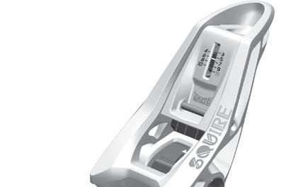
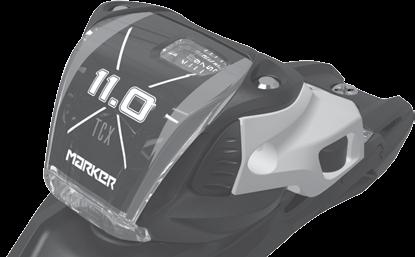
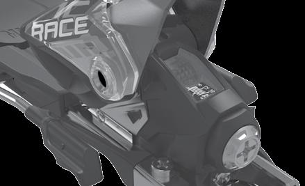


56 11.2 ADJUSTMENTS 11.2 RELEASE VALUE SELECTION AND ADJUSTMENT 11.2 RELEASE VALUE SELECTION AND ADJUSTMENT Triple Pivot Elite 2 2 BINDING RELEASE FORCE ADJUSTMENT SCREWS AND RELEASE VALUE INDICATOR SCALES MARKER recommends adjustment with a Pozidriv 3 screwdriver. Inter Pivot ADJUSTMENTS Xcell 2 1 ADJUSTMENT SCREW AND INDICATOR SCALE ON THE TOE Turn the adjustment screw (1) until the indicator line aligns with the selected release setting on the appropriate indicator scale. (2) Hollow linkage 4 3 ADJUSTMENT SCREW AND INDICATOR SCALE ON THE HEEL Turn the adjustment screw (3) until the indicator line aligns with the selected release setting on the appropriate indicator scale. (4) 1 2 Triple Pivot X Triple Pivot Compact Twincam X Comfort linkage (TLT2) 2 2 Triple Pivot Comfort TCX light 4 Compact Triple Pivot light Biotech Junior 4 - linkage Compact 3 Compact Junior
57 11.3 ADJUSTMENTS 11.3 FUNCTION TEST AND INSPECTION 11.4 TROUBLE - SHOOTING After installation, adjustment and function test have been duly carried out, the binding should be tested with a calibrated testing device for ski bindings. See the information given by the manufacturer of the ski binding test device. This function test should verify that the release torque ranges (mentioned in Nm) are within the limits of the tolerances and should be noted on a workshop form. RELEASE VALUE TOLERANCE: A release value tolerance of ± 15 % is valid according to ISO This equals a value in the MARKER adjustment chart in an area one line up and down of the chosen release value. See example , equivalent to B. If the measured value is in this area, the system can receive clearance. LIMITING VALUE FOR NEW ADJUSTMENTS: A release value limit of ± 30 % is valid for new adjustments according to ISO This equals a value in the MARKER adjustment chart in an area two lines up and down of the chosen release value. See example , equivalent to C. If the measured value is in the area for a new adjustment (value C), the system may not be delivered. Inspect again the consistency of ski boot and binding and verify the adjustment of the binding. Re - test the binding. If the measured value is still in the area for a new adjustment, correct the adjustment of the binding until the measured value is within the release value tolerance (value B). If the measured values are beyond the limits for a new adjustment value C, it is not allowed to correct the adjustment of the binding. Replace ski boot, binding or both. DELIVERY TO THE CUSTOMER: EXAMPLE After all adjustments are done, deliver the customer the whole system together with a function test report (workshop form). Fix the data as mentioned in chapter 14»workshop records«beside the result of the measurement. 4 3,50 J C 5 4,50 K B 6 5,50 L RELEASE VALUE 7 6,50 M B 8,50 8 N C INSPECTION FOR NEW AND USED BINDINGS: After you have set each toe and heel piece to the correct release value setting, perform the following test: Be sure that the ski and boot meet the visual inspection criteria described in chapter 2. FUNCTION TEST TOE: All used bindings should be cleaned before performing any inspections. Do not lubricate the gliding AFD, toe cups or heel cups. Lateral elastic travel and return: With the ski held firmly, hit the forefoot of the boot with your hand or a rubber mallet. Displace the toe of the boot slightly (6 10 mm) through the retention zone but not far enough to trigger a release. The boot should travel back quickly and smoothly to the middle point. If the toe of the boot travels far enough to activate a partial release, re - insert the boot and re - test before continuing with any further inspection. Release the boot from the binding to the left and to the right. Proceed to function test the heel. IF THE SYSTEM PASSES: Verify the release values with the testing device. IF THE SYSTEM FAILS: Check that the boot was not displaced far enough to trigger a release. Check if the binding - to - boot adjustment is properly done. If not, re - adjust. Check that the boot is centered in the heel cup. Re - insert the boot. Check the gliding AFD for damage. Replace the toe if necessary. Check for non - standard boot or excessive wear. Replace boot if necessary. Check the toe for excessive wear or damage. Replace the toe if necessary. TOE PIECE LOOSE: Check for missing, stripped or loose screws. Repair or replace if necessary. FUNCTION TEST HEEL: The following test is for all step - in heels. Test for vertical elastic travel and return: Depress the opening lever of the binding while pulling forward lightly on the upper cuff of the boot. The heel of the boot should move slightly upward (about 5 mm) through the vertical retention range of the heel. Release both hands simultaneously. The boot should return quickly to the ski, and the opening lever should return quickly to its fullest upright position. If using a test device follow the manufacturer s instructions. IF THE SYSTEM PASSES: Verify the release values with the testing device. IF THE SYSTEM FAILS: Heel will not close or closes with difficulty: Check for snow or dirt under the boot heel. Clean the sole if necessary. Check length adjustment and forward pressure. Re - adjust if necessary. Check for non - standard boot or excessive wear. Replace boot if necessary. Check that the boot enters the binding correctly. Confirm that the boot - to - binding contact is exact. BOOT SLIDES IN HEEL SOLEHOLDER: Check that the forward pressure is not too low. Check for lubricant on boot or soleholder. Clean binding and boot ADJUSTMENTS BOOT SLIDES IN TOE CUP: Check that the forward pressure is not too low. Check for lubricant on boot or toe cups. Clean binding and boot


58 SPECIAL CASES / REPLACING SKI BRAKES SPECIAL CASES / REPLACING SKI BRAKES 12.1 COMPETITION BINDINGS: For racers MARKER offers special competition ski bindings with higher release values. Please advise your customer that skiers skiing on such bindings are doing so at their own risk and liability MONOSKI: MARKER ski bindings are designed for the use on a pair of skis. Any other use or the installation on a Monoski will not be covered by MARKER s indemnification or warranty ADJUSTMENT OUTSIDE OF THE STANDARDS: If skiers request a release setting other than that recommended by the MARKER adjustment chart in this manual or not in accordance with the standards, the shop may choose to adjust the system to MARKER s recommendations and instruct the skiers on how to change the setting themselves, should they wish to. As a service to the skier the shop may wish to adjust the skier s system in accordance with the skier s wishes, even when this requested setting would fall outside of the MARKER adjustment chart s recommendations. If the shop provides this type of service, the system will only be indemnified if the skier signs a release agreement in which he declares that the adjustment has be done at the skier s own risk REPLACING SKI BRAKES: Within the scope of the binding adjustment the ski brakes should be subjected to a visual and functional test. If the brakes are defective (if the brake arms are damaged, the brake platform or brake pedal are worn) or a wider brake is necessary the pair of brakes should be replaced. MARKER offers ski brakes with different widths for replacement. REMARK To determine the correct brake the width of the ski has to be measured ca. 200 mm behind the mid ski mark. Replacing ski brakes see Brake chart see REPLACING SKI BRAKES REPLACING THE SKI BRAKES INTER - PIVOT AND TOUR / SQUIRE: DEMOUNT THE SKI BRAKE: Remove the attachment screws of the ski brake (12.6-1). Pull the ski brake forward to remove (12.6-2). INSTALL THE NEW SKI BRAKE: Slide in the ski brake. Make sure that the new brake is fully and uniformly sliding into the attachments of the heel plate (12.6-3) REPLACING SKI BRAKES 12.4 ANTIQUATED BINDINGS WHICH DO NOT CONFORM WITH THE STANDARD: Slide the ski brake backward until it stops. (12.6-3). Shops may choose to work on bindings not indemnified by MARKER at their discretion. If a skier asks the retailer to perform work on antiquated or non - standard MARKER bindings, the system should be inspected according to the procedures described in the appropriate chapter of this manual. (Be certain to explain to the skier the advantages of using a current model!) If the system passes the inspections, for the shop s own legal protection the shop should ask the skier to sign a waiver and release. Tighten the attachment screws of the ski brake (12.6-4). If the system fails any of these inspections, a notation to this effect must be made on the workshop form and the skier must be warned that continued use of the system is inadvisable and may significantly increase the skier s risk of injury The wide ski brakes are replaceable in the same manner. see BRAKE CHART

. 12.")

.")
. INSTALL THE NEW SKI BRAKE: Slide in the ski brake.")
 12.")

. 12.7-3 Slide the ski brake backward until it stops. 12.8-4 Tighten the attachment screws carefully by hand (12.")

59 12.7 REPLACING SKI BRAKES 12.7 REPLACING SKI BRAKES 12.8 REPLACING SKI BRAKES REPLACING THE SKI BRAKES RACE XCELL, RACE 10 & 8, 11.0 TC: DEMOUNT THE SKI BRAKE: Remove the attachment screw of the ski brake (12.7-1) REPLACING THE SKI BRAKES 10.0 EPS / FREE TEN / FREE 8: DEMOUNT THE SKI BRAKE: Remove the ski brake attachment screws (12.8-1) REPLACING SKI BRAKES Pull the ski brake slightly forward to remove (12.7-2). Pivot the rear brake platform hooks carefully to remove the ski brake (12.8-2). INSTALL THE NEW SKI BRAKE: Slide in the ski brake. Make sure that the metal hooks of the brake base latch beneath the metal base plate of the heel. (12.7-3) INSTALL THE NEW SKI BRAKE: Engage the front of the brake platform and feed the rear hooks into the notches of the spacer. Make sure that the new brake is locked in place ( and ) Slide the ski brake backward until it stops Tighten the attachment screws carefully by hand (12.8-5). Tighten the attachment screw of the ski brake (12.7-4). Tighten the screws by hand, do not use a power drill! The wide ski brakes are replaceable in the same manner The wide ski brakes are replaceable in the same manner. see BRAKE CHART 15.2 see BRAKE CHART


 12.9-7 12.")

 12.9-8 ø 2.")


60 12.9 DIN ADAPTER AT BOOT 12.9 DIN ADAPTER AT BOOT 12.9 DIN ADAPTER AT BOOT Mount the Marker DIN adapter on the heel. While doing so, check that there is no gap between the edge of the boot heel and the DIN adapter ( and ). If applicable, hit the centre of the DIN adapter with a rubber mallet DIN ADAPTER AT BOOT DIN - ADAPTER AT BOOT FOR DYNAFIT TLT 5 + TLT 6 BOOTS Use the original screw from your boot to fix the DIN adapter to the boot. (12.9-6) Tools required for assembly: DIN Adapter, Power drill, Drill bit size 2, small slotted screwdriver, Phillips head screwdriver size PH2, Torx screwdriver size 10 (12.9-1) ø 2.0 mm Dynafit TLT 5 + TLT 6 boots There are drill holes at both ends of the DIN adapter. Drill into these holes that are around 5 mm deep with a 2.0 mm drill bit. ( and ) Front drill holes: for DYNAFIT TLT 5 + TLT 6 boots Use the Phillips head screwdriver to unscrew the screw with which the heel insert is fixed in place. (12.9-2) Nm Then tighten the Torx screws supplied using the manual screwdriver with 0.2 Nm. ( and ) Then remove the heel insert. This can be gently levered out using a small slotted screwdriver. ( and )
 MARKER Jester Demo have adjustable toes and adjustable heels.")
 MARKER Griffon D & Squire D models have adjustable toes and adjustable heels. 13.1-5 13.")
 is")
 mm toe heel Griffon D Squire D 260-388 64 mm 64 mm Griffon D & Squire D: Sole length in mm (260")
 The Fastrak III System is adjustable by a centralized length adjustment system. Adjustment range (in 4 mm steps) mm toe heel 10.")
61 13.1 MARKER RENTAL & DEMO MODELS 13.1 GENERAL INFORMATION 13.1 GENERAL INFORMATION DEFINITION OF JESTER DEMO BINDINGS: (13.1-1) MARKER Jester Demo have adjustable toes and adjustable heels. Adjustment range mm toe heel Jester Demo mm 50 mm DEFINITION OF GRIFFON D & SQUIRE D BINDINGS: (13.1-2) MARKER Griffon D & Squire D models have adjustable toes and adjustable heels GENERAL INFORMATION BINDING - TO - BOOT ADJUSTMENT For the correct binding - to - boot adjustment there are number codes, respectively sole length scales on the Jester Demo, Griffon D & Squire D, FDT Demo, Fastrak III, Junior Fastrak II, Junior RTL and FDT Junior bindings: Jester Demo: Sole length in mm ( ) is marked on the toe - and heel plates. (13.1-5) 13.1 MARKER RENTAL & DEMO MODELS Adjustment range (in 4 mm steps) mm toe heel Griffon D Squire D mm 64 mm Griffon D & Squire D: Sole length in mm ( ) is marked on the Griffon D / Squire D toe - and heel plates. (13.1-6) DEFINITION OF FASTRAK III BINDINGS: (13.1-3) The Fastrak III System is adjustable by a centralized length adjustment system. Adjustment range (in 4 mm steps) mm toe heel 10.0 Fastrak III mm Fastrak III: Sole length in mm ( ) is marked on the Fastrak III middle plate. (13.1-7) DEFINITION OF FDT BINDINGS: (13.1-4) MARKER FDT bindings have adjustable toes and adjustable heels. Adjustment range (in 4 mm steps) mm toe heel FDT TPX FDT TP FDT TLT mm 64 mm FDT Demo models: Sole length in mm ( ) is marked on the FDT Demo middle plate. (13.1-8)
 Junior Fastrak II bindings have movable toes and movable heels. Adjustment range (toe: in 5 mm steps, heel in 4 mm steps) mm toe heel 7.0 Fastrak II 86 50 36 4.")

 7.0 RTL Code 54 69 240 304 mm 4.5 RTL Code 44 59 200 264 mm 13.1 MARKER RENTAL & DEMO MODELS 4.5 RTL 200-264 - 64 mm 13.1-11 13.")
62 13.1 MARKER RENTAL & DEMO MODELS 13.1 GENERAL INFORMATION 13.1 GENERAL INFORMATION DEFINITION OF JUNIOR FASTRAK II BINDINGS: (13.1-9) Junior Fastrak II bindings have movable toes and movable heels. Adjustment range (toe: in 5 mm steps, heel in 4 mm steps) mm toe heel 7.0 Fastrak II Fastrak II DEFINITION JUNIOR RENTAL BINDINGS: ( ) Junior Rental (RTL) bindings have fixed toes and movable heels. Adjustment range (in 4 mm steps) mm toe heel 7.0 RTL mm GENERAL INFORMATION BINDING - TO - BOOT ADJUSTMENT Junior Fastrak II: Sole length in mm ( mm large; mm small) is marked on the Junior Fastrak II toe - and heel plates. ( ) 7.0 / 4.5 RTL: Number codes are placed on the heel spacers. ( ) 7.0 RTL Code mm 4.5 RTL Code mm 13.1 MARKER RENTAL & DEMO MODELS 4.5 RTL mm DEFINITION OF FDT JUNIOR BINDINGS: ( ) FDT Junior bindings have movable toes and movable heels. Adjustment range (in 4 mm steps) mm toe heel FDT Junior: Sole length in mm ( mm large; mm small) is marked on the FDT Junior toe - and heel plates. ( ) FDT mm 48 mm FDT mm 48 mm


 onto the ski and align the mid - sole mark»jester Demo«with the mid - sole mark on the ski.")

: Adjusting the installation tool W001G1T or W012J1T (13.")
 Close the locking lever.")
63 13.2 MARKER RENTAL & DEMO MODELS 13.2 INSTALLATION OF MARKER JESTER DEMO 13.2 INSTALLATION OF MARKER JESTER DEMO A 1 MARKER JESTER DEMO 1 Front plate with sole length scale 2 Heel plate with sole length scale 3 Length adjustment screw The binding models Jester Demo are equipped with an additional sole length scale. This additional scale can be mounted between ski and the heel plate when required.(13.2-4) 13.2 MARKER RENTAL & DEMO MODELS toe B heel these binding models are designed for use only with Alpine ski boots for adults DIN ISO 5355 type A. DRILLING THE ATTACHMENT HOLES (A): Place the Jester Demo installation tool W005L1T or W009P1T ( A) onto the ski and align the mid - sole mark»jester Demo«with the mid - sole mark on the ski. Check if the installation tool is positioned correctly on the ski. Drill 5 holes for the front plate and 4 holes for the heel plate through the black marked drill bushings. Remove installation tool from the ski Slide the heel onto the heel plate, starting from the front. Slide the heel back until it stops. (13.2-5) or mm DRILLING THE ATTACHMENT HOLES (B): Adjusting the installation tool W001G1T or W012J1T ( B) for mounting the MARKER Jester Demo: Open the locking lever. Move the toe guide until the sole length 315 mm is adjusted. (13.2-2) Close the locking lever. Place the pre - installed installation tool onto the ski and align the mid - sole mark of the installation tool with the mid - sole mark on the ski. Drill 4 holes for the front plate (toe) through the red marked drill bushings, drill the additional rear hole for the front plate through the rear toe bushing. (13.2-1) Drill 4 holes for the heel plate (heel) through the red marked drill bushings. Remove installation tool from the ski Ensure that the heel is fully and uniformly sliding into the heel plate attachments. (13.2-6) ski tip See the DRILLING INSTRUCTIONS 3.2 Move the heel backwards by turning the forward pressure adjustment screw. (13.2-7) INSTALLING THE HEEL: Install the MARKER Jester Demo heel plate with the 4 pre - installed screws (13.2-3). Tighten the screws lightly, then firmly

 INSTALLING THE TOE: Install the MARKER Jester Demo front plate with the 5 pre - installed screws (13.2-9).")
 Screw the toe backward to the correct sole length in accordance with the sole length scale.")


64 13.2 MARKER RENTAL & DEMO MODELS 13.2 INSTALLATION OF MARKER JESTER DEMO 13.2 INSTALLATION OF MARKER JESTER DEMO ski tip Screw the heel backward to the correct sole length in accordance with the sole length scale. Indicator: back edge of the heel housing left and right. (13.2-8) INSTALLING THE TOE: Install the MARKER Jester Demo front plate with the 5 pre - installed screws (13.2-9). Tighten the screws lightly, then firmly With slight pressure, screw the toe backwards onto the front plate. ( ) Screw the toe backward to the correct sole length in accordance with the sole length scale. Indicator: back edge of the toespacer left and right ( ) IMPORTANT SAFETY ADVICE! Make sure that you do not exceed the»stop«marking on the front plate! Sole length adjustment 365 = max! ( ) CHECK FORWARD PRESSURE: 13.2 MARKER RENTAL & DEMO MODELS Place the ski boot into the binding, close the binding. Check if the forward pressure adjustment screw is flush with the back of the heel housing. ( ). If this adjustment is incorrect, turn the screw until it is flush with the back of the housing. Remove the ski boot, then re - insert it into the binding and recheck the adjustment. Slide the toe onto the toe plate, starting from the front. Slide the toe back until it stops. ( ) RELEASE VALUE SELECTION AND ADJUSTMENT: Ls 365 = max Following the correct adjustment for sole length and forward pressure, the release value has to be selected and adjusted. Use the weight method to match the individual skier s needs. See RELEASE VALUE SELECTION AND ADJUSTMENT: ADJUSTMENT OF DEMO BINDING MODELS: also refer to chapter 13.8 Ensure that the toe is fully and uniformly sliding into the front plate attachments. ( ) The release value selection and adjustment has to be done very accurately to care for the skier s safety. All key information including the release value must be recorded in the workorder


 13.3-6 13.3-7 13.3-8 13.3-9 Close the toe locking lever. (13.")
 Slide the heel forward. (13.3-8) Ensure that the rails of the heel engage both sides of the base plate properly.")
 Close the heel locking lever. (13.3-10) CHECK FORWARD PRESSURE: Place the ski boot into the binding, close the binding.")


65 13.3 MARKER RENTAL & DEMO MODELS 13.3 INSTALLATION OF MARKER GRIFFON D & SQUIRE D & FDT MODELS 13.3 INSTALLATION OF MARKER GRIFFON D & SQUIRE D & FDT MODELS FDT Griffon D / Squire D and FDT bindings are designed to mount only in conjunction with the FDT plate system. DRILLING THE ATTACHMENT HOLES: Place the FDT installation tool W009P1T or W004Q1T (13.3-1) onto the ski and align the mid - sole mark»fdt«with the mid - sole mark on the ski. Check if the installation tool is positioned correctly on the ski. Drill 4 holes for the front plate and 4 holes for the heel plate through the yellow marked drill bushings. Remove the installation tool from the ski. See the DRILLING INSTRUCTIONS 3.2 INSTALLATION OF THE FDT PLATE: Place the FDT plate onto the ski, tighten the front plate screws lightly, then firmly. Tighten the heel plate screws lightly, then firmly. (13.3-2) Close the toe locking lever. (13.3-6) INSTALLING THE HEEL: Open the heel locking lever and slide the heel onto the plate starting from the rear. (13.3-7) Slide the heel forward. (13.3-8) Ensure that the rails of the heel engage both sides of the base plate properly. Slide the heel to the correct sole length in accordance with the rear sole length scale. (13.3-9) Close the heel locking lever. ( ) CHECK FORWARD PRESSURE: Place the ski boot into the binding, close the binding. Correct forward pressure: With the boot in the system the forward pressure is correct when the imprinted line on the forward pressure indicator is visible in the cutout of the heel housing. ( ) If the forward pressure indicator line is not visible: remove the ski boot and readjust the boot sole length until the forward pressure indicator line is visible in the cutout MARKER RENTAL & DEMO MODELS This mounting instruction is also valid for the MARKER / NORDICA models FDT, MARKER / MOVEMENT models FDT and the MARKER / Bogner & Indigo models FDT. The binding models Griffon D, Squire D & FDT GRIPWALK are designed for the following standard boot soles: Alpine ski boots for adults DIN ISO 5355 Touring ski boots for adults DIN ISO 9523 with the additional marking "Gripwalk " RELEASE VALUE SELECTION AND ADJUSTMENT: Following the correct adjustment for sole length and forward pressure, the release value has to be selected and adjusted. Use the weight method to match the individual skier s needs. See RELEASE VALUE SELECTION AND ADJUSTMENT: INSTALLING THE TOE: Open the locking lever and slide the toe from the center of the plate forward. ( & ) ADJUSTMENT OF DEMO BINDING MODELS: also refer to chapter Make sure that the toe spacer rails engage both sides of the base plate properly. Slide the toe to the correct sole length in accordance with the front sole length scale. (13.3-5) The release value selection and adjustment has to be done very accurately to care for the skier s safety. All key information including the release value must be recorded in the workorder


 Lock the system by closing the sole length fixation lever. (13.4-6) 13.")
 onto the ski and align the mid - sole mark»adult«with the mid - sole mark on the ski.")


66 13.4 MARKER RENTAL & DEMO MODELS 13.4 INSTALLATION OF 10.0 FASTRAK III & 10.0 FASTRAK III TP 13.4 INSTALLATION OF 10.0 FASTRAK III & 10.0 FASTRAK III TP FASTRAK III M 10.0 Fastrak III & 10.0 Fastrak III TP bindings are designed to mount only in conjunction with the Fastrak III plate system! This mounting instruction is also valid for the MARKER / K 2 models Fastrak 3 10 & Fastrak 3 10 TP these binding models are designed for use only with Alpine ski boots for adults DIN ISO 5355 type A Adjust the system to max. length. (13.4-5) Lock the system by closing the sole length fixation lever. (13.4-6) 13.4 MARKER RENTAL & DEMO MODELS DRILLING THE ATTACHMENT HOLES: Place the Fastrak III installation tool W003H1T (13.4-1) onto the ski and align the mid - sole mark»adult«with the mid - sole mark on the ski. Check if the installation tool is positioned correctly on the ski. Drill 4 holes for the front plate and 4 holes for the heel plate through the green marked drill bushings. Remove installation tool from the ski To attach the binding system Fastrak III to the plate, position the toe spacer at the middle section of the plate. (13.4-7) See the DRILLING INSTRUCTIONS 3.2 INSTALLATION OF THE FASTRAK III PLATE: Place the heel plate onto the ski, the plate area with the premounted steel plate must be forward (toward ski tip). Tighten the screws lightly, then firmly. (13.4-2) Slide the system forward. (13.4-8) Place the toe plate onto the ski, tighten the screws lightly, then firmly. (13.4-3) B Push the opening block [A], then lift the sole length fixation lever [B]. (13.4-4) B Push the opening block [A], then lift the sole length fixation lever [B]. (13.4-9) A A

 Position the center fixation screw. (13.4-13) With light downward pressure, tighten the screw by hand with a maximum torque of 4.")
 13.4-17 13.4-18 13.4-14 13.4-19 Lock the system by closing the sole length fixation lever. (13.")

 CHECK FORWARD PRESSURE: Place the ski boot into the binding, close the binding.")
.")


 (13.")

67 13.4 MARKER RENTAL & DEMO MODELS 13.4 INSTALLATION OF 10.0 FASTRAK III & 10.0 FASTRAK III TP 13.4 INSTALLATION OF 10.0 FASTRAK III & 10.0 FASTRAK III TP Make sure that the toe and heel spacer rails engage both sides of the base plate properly ( and ) Slide the binding system forward until the hole of the middle plate and the hole of the steel plate are aligned. ( ) Position the center fixation screw. ( ) With light downward pressure, tighten the screw by hand with a maximum torque of 4.0 ± 0.2 Nm. ( ) Lock the system by closing the sole length fixation lever. ( ) The sole length fixation lever must not be pressed down with effort, but is correctly aligned with the locking teeth when it closes easily. Visually check locking mechanism: when locking the system the opening lever has snap into the basic position. ( ) The warning symbol on the right side of the opening lever must not be visible! ( ) CHECK FORWARD PRESSURE: Place the ski boot into the binding, close the binding. Correct forward pressure: With the boot in the system the forward pressure is correct when any portion of the white scribe mark on the forward pressure indicator is flush with the back edge of the heel housing. ( ). If the forward pressure is incorrect: remove the ski boot and readjust the boot sole length until the forward pressure is correct. RELEASE VALUE SELECTION AND ADJUSTMENT: 13.4 MARKER RENTAL & DEMO MODELS Following the correct adjustment for sole length and forward pressure, the release value has to be selected and adjusted. Use the weight method to match the individual skier s needs. See RELEASE VALUE SELECTION AND ADJUSTMENT: SOLE LENGTH ADJUSTMENT Adjust the sole length either by hand by shifting the binding to the corresponding markings on the scale or by turning the sole length adjustment screw with the appropriate screwdriver (Use a Pozidriv 3 screwdriver) ( ) The release value selection and adjustment has to be done very accurately to care for the skier s safety. All key information including the release value must be recorded in the workorder ADJUSTMENT OF DEMO BINDING MODELS: also refer to chapter The sole length scale is equipped with an additional color code. (MARKER 10.0 Fastrak III & Fastrak III TP) This color code corresponds with the Dalbello 4 - factor rental boot code system C A B DISASSEMBLY OF THE SYSTEM: For disassembling the system first adjust the sole length to maximum. Remove the central fixation screw. Lift the middle plate section with a small screwdriver out of the catch mechanism and slide the binding system rearwards from the plate. ( )


 onto the ski and align the mid - sole mark»junior small«or»junior large«with the mid - sole mark on the ski. Check if the installation tool is positioned correctly on the ski.")

68 13.5 MARKER RENTAL & DEMO MODELS 13.5 INSTALLATION OF JUNIOR FASTRAK II 13.5 INSTALLATION OF JUNIOR FASTRAK II FASTRAK II JUNIOR LARGE M 7.0 Fastrak II and M 4.5 Fastrak II bindings are designed to mount only in conjunction with the Fastrak II Junior large oder Fastrak II Junior small plate systems! INSTALLING THE JUNIOR FASTRAK II TOE: Open the toe locking lever by lifting it up and backwards. (13.5-4) 13.5 MARKER RENTAL & DEMO MODELS FASTRAK II JUNIOR SMALL These binding models will accommodate both adult and junior Alpine boots DIN ISO Slide the toe with lever open from the center of the plate forward. (13.5-5) JUNIOR FASTRAK II: DRILLING THE ATTACHMENT HOLES: Place the Fastrak II installation tool W003H1T (13.5-1) onto the ski and align the mid - sole mark»junior small«or»junior large«with the mid - sole mark on the ski. Check if the installation tool is positioned correctly on the ski.»junior small«: Drill 4 holes for the front plate and 4 holes for the heel plate through the yellow marked drill bushings.»junior large«: Drill 4 holes for the front plate and 4 holes for the heel plate through the violet marked drill bushings. Remove installation tool from the ski Ensure that the rails of the toe engage both sides of the base plate properly. (13.5-6) See DRILLING INSTRUCTIONS INSTALLATION OF THE JUNIOR FASTRAK II PLATE: Place the toe plate onto the ski, the length scale points to the ski tail. Tighten the screws lightly, then firmly. (13.5-2) Place the heel plate onto the ski, the metal bracket points to the ski tail. Tighten the screws lightly, then firmly. (13.5-3) Slide the toe forward to the correct sole length in accordance with the sole length scale. (13.5-7)


 RELEASE VALUE SELECTION AND ADJUSTMENT: 13.")


69 13.5 MARKER RENTAL & DEMO MODELS 13.5 INSTALLATION OF JUNIOR FASTRAK II 13.5 INSTALLATION OF JUNIOR FASTRAK II Close the locking lever. Ensure that the lever is engaged properly. (13.5-8) INSTALLING THE JUNIOR FASTRAK II HEEL: Install the heel by fitting the spacer into the notches of the heel plate. (13.5-9) Lift the locking lever and slide the heel to the correct sole length in accordance with the sole length scale. ( ) Latch the locking lever by locking it down until fixed. ( ) Ensure that the lever is engaged properly! CHECK FORWARD PRESSURE: Place the ski boot into the binding, close the binding. Correct forward pressure: With the boot in the system the groove on the locking lever has to point to the embossed section of the heel housing. If the forward pressure is incorrect: remove the ski boot, lift the lever and move the heel until the forward pressure is correct. ( ) RELEASE VALUE SELECTION AND ADJUSTMENT: 13.5 MARKER RENTAL & DEMO MODELS Following the correct adjustment for sole length and forward pressure, the release value has to be selected and adjusted. Use the weight method to match the individual skier s needs. See RELEASE VALUE SELECTION AND ADJUSTMENT: Slide the heel backwards until the heel spacer engages the plate, then lift the locking lever and move the heel backwards. ( ) The release value selection and adjustment has to be done very accurately to care for the skier s safety. All key information including the release value must be recorded in the workorder The easiest way to adjust the heel is moving it with open soleholder. ADJUSTMENT OF DEMO BINDING MODELS: also refer to chapter Ensure that the rails of the heel engage both sides of the base plate properly. ( )
 have to be mounted with the installation tool W007H1T (13.6-1)! 13.6-5 13.")
 The easiest way to adjust the heel is moving it with open soleholder.")
 13.6 MARKER RENTAL & DEMO MODELS 13.6-2 DRILLING THE ATTACHMENT HOLES: Adjusting the installation tool (W007H1T) for 4.")


70 13.6 MARKER RENTAL & DEMO MODELS 13.6 INSTALLATION OF 7.0 RTL / 4.5 RTL 13.6 INSTALLATION OF 7.0 RTL / 4.5 RTL toe heel INSTALLATION OF 7.0 / 4.5 RTL: 4.5 RTL and 7.0 RTL (with length scales and 54 69) have to be mounted with the installation tool W007H1T (13.6-1)! B INSTALLING THE HEEL: Place the heel with the pre - installed screws onto the ski. Tighten the screws lightly, then firmly. (13.6-5) Check if all screws are tightened firmly. ADJUST THE CODE ON THE BINDING: (see 13.1) The easiest way to adjust the heel is moving it with open soleholder. Pull the locking lever upward (A) and move the heel until the indicator on the side of the heel housing is aligned with the determined code. (13.6-6) Close the locking lever to secure heel position. Ensure that the lever is engaged properly! (13.6-7) 13.6 MARKER RENTAL & DEMO MODELS DRILLING THE ATTACHMENT HOLES: Adjusting the installation tool (W007H1T) for 4.5 RTL: Open the locking lever. Move the toe guide until the marking sticker on the toe guide is aligned with the marking»a«on the frame of the installation tool. Fix the position by inserting a drill bit to the position»a«hole. Close the locking lever, remove the drill bit. Place the pre - installed installation tool onto the ski and align the mid - sole mark boot center Child RTL with the mid - sole mark on the ski. (13.6-2) A CHECK FORWARD PRESSURE: Place the ski boot into the binding, close the binding. Correct forward pressure: With the boot in the system the groove on the locking lever has to point to the embossed section of the heel housing (13.6-8). If the forward pressure is incorrect: remove the ski boot, lift the lever and move the heel until the forward pressure is correct A boot center Child - RTL Adjusting the installation tool (W007H1T) for 7.0 RTL: Open the locking lever. Move the toe guide until the marking sticker on the toe guide is aligned with the marking»b«on the frame of the installation tool. Fix the position by inserting a drill bit to the position»b«hole. Close the locking lever, remove the drill bit. Place the pre - installed installation tool onto the ski and align the mid - sole mark boot center Junior RTL with the mid - sole mark on the ski. (13.6-3) RELEASE VALUE SELECTION AND ADJUSTMENT: Following the correct adjustment for sole length and forward pressure, the release value has to be selected and adjusted. Use the weight method to match the individual skier s needs. See RELEASE VALUE SELECTION AND ADJUSTMENT: B boot center Junior - RTL Drill 3 holes for the toe through the front bushings and 4 holes for the heel through the grey marked rear drill bushings. Remove installation tool from the ski. See DRILLING INSTRUCTIONS 3.2 These binding models will accommodate both adult and junior Alpine boots DIN ISO ADJUSTMENT OF DEMO BINDING MODELS: also refer to chapter 13.8 The release value selection and adjustment has to be done very accurately to care for the skier s safety. All key information including the release value must be recorded in the workorder INSTALLING THE TOE: Place the toe with the pre - installed screws onto the ski. Tighten the screws lightly, then firmly. (13.6-4)


 onto the ski and align the mid - sole mark»fdt Junior small«or»fdt Junior large«with the mid - sole mark on the ski.")


 Ensure that the rails of the heel engage both sides of the base plate properly.")


71 13.7 MARKER RENTAL & DEMO MODELS 13.7 INSTALLATION OF FDT 7.0 / FDT INSTALLATION OF FDT 7.0 / FDT FDT Junior large FDT Junior small FDT 7.0 and FDT 4.5 bindings are designed to mount only in conjunction with the FDT Junior large or FDT Junior small plate systems! VMOTION Junior and VMOTION Junior R bindings are designed to mount only in conjunction with VMOTION Junior skis with premounted plates! FDT JUNIOR: DRILLING THE ATTACHMENT HOLES: Place the FDT Junior installation tool W003H1T (13.7-1) onto the ski and align the mid - sole mark»fdt Junior small«or»fdt Junior large«with the mid - sole mark on the ski. Check if the installation tool is positioned correctly on the ski.»fdt Junior small«: Drill 4 holes for the front plate and 4 holes for the heel plate through the yellow marked drill bushings.»fdt Junior large«: Drill 4 holes for the front plate and 4 holes for the heel plate through the violet marked drill bushings. Remove installation tool from the ski INSTALLING THE HEEL: Open the heel locking lever and slide the heel onto the plate starting from the center. ( & ) Slide the heel backward. (13.7-8) Ensure that the rails of the heel engage both sides of the base plate properly. Slide the heel to the correct sole length in accordance with the rear sole length scale. (13.7-9) Close the heel locking lever. ( ) 13.7 MARKER RENTAL & DEMO MODELS max. 3 Nm See DRILLING INSTRUCTIONS 3.2 These binding models will accommodate both adult and junior Alpine boots DIN ISO INSTALLATION OF THE FDT JUNIOR PLATE: Place the toe plate onto the ski, the length scale points to the ski tail. Place the heel plate onto the ski, the metal bracket points to the ski tail. Tighten the screws by hand with a max. torque of 3 Nm. (13.7-2) CHECK FORWARD PRESSURE: Place the ski boot into the binding, close the binding. Correct forward pressure: With the boot in the system the forward pressure indicator on the locking lever has to point to the marked section on the side of the heel housing. ( ) If the forward pressure is incorrect: remove the ski boot, lift the lever and move the heel until the forward pressure is correct. RELEASE VALUE SELECTION AND ADJUSTMENT: Following the correct adjustment for sole length and forward pressure, the release value has to be selected and adjusted. Use the weight method to match the individual skier s needs. See RELEASE VALUE SELECTION AND ADJUSTMENT: INSTALLING THE TOE: Open the locking lever and slide the toe from the center of the plate forward. ( & ) ADJUSTMENT OF DEMO BINDING MODELS: also refer to chapter Make sure that the toe spacer rails engage both sides of the base plate properly. Slide the toe to the correct sole length in accordance with the front sole length scale. (13.7-5) The release value selection and adjustment has to be done very accurately to care for the skier s safety. All key information including the release value must be recorded in the workorder Close the toe locking lever. (13.7-5)
72 13.8 MARKER RENTAL & DEMO MODELS 13.8 FUNCTION TEST AND SERVICE 13.8 FUNCTION TEST AND SERVICE FUNCTION TEST OF MARKER RENTAL & DEMO BINDINGS: TEST PROCEDURE: Since it is impractical to perform a full inspection each time a system is rented, a routine of pre - season and in - season inspections has been developed to verify release indicator accuracy, confirm correct equipment function, and assure proper assembly and adjustment procedures by the rental shop staff. Fully implemented, the procedures that follow provide rental shop customers a standard of care equivalent to that provided retail shop customers under current ISO and ASTM standards. The program is based on the existing standards: ISO and ASTM F1064. PRE - SEASON INSPECTION Pre - season inspections are performed on components of the release system: bindings and boots. All rental bindings, new and used, are visually inspected, and then tested using specially selected reference boots. Bindings that fail go through a trouble - shooting procedure ( 11.4) to identify and correct the deviation or malfunction. If this procedure does not correct the problem, the binding is removed from inventory. All rental boots, new and used, are visually inspected for damage, wear, contamination, broken or missing parts, or inferior materials at contact points with the binding. In addition, one boot per cell is tested for boots that are new to the rental inventory. A cell is all boots of the same make, model, age, and shell size. A random selection of 5 % of all boots, previously accepted into inventory, is also tested. Tests are performed with a test device and a pair of specially selected reference bindings. If a boot fails, all boots from that cell are then tested. Boots that fail and cannot be repaired are removed from inventory. IN - SEASON INSPECTION In - season inspections are performed on complete rental systems to ensure that the equipment is adjusted appropriately and continues to function correctly. Typically 5 % of the rental inventory is tested during each two week sampling period. The random sample is equally divided between equipment that is available for rental and equipment that has just been rented. The equipment in the as rented category is from real skiers in the condition in which it is either dispatched or returned, while the available for rental equipment may be set up for fictitious skiers. Only single skis, not pairs, are tested, and testing at the toe is only required in one direction. A count is maintained of test results which exceed allowable limits. The magnitude and frequency of these deviations determines the frequency of future inspections. Shops which fail an inspection must sample daily until the source of the problem is found and corrected. Then, as inspection results improve, the frequency of sampling and inspection is relaxed. INSPECTION PROCEDURES IMPORTANT TERMS CORRECTION FACTOR The value that must be added or subtracted from the initial visual indicator setting to bring the test result within the Inspection Tolerance (or Inspection Range). DIRECTIONS OF RELEASE Unless otherwise specified (see in-season inspection), the directions of release to be tested are forward lean and clockwise and counter clockwise in twist. TEST DEVICE A device which meets ISO standard or ASTM standard F1061 and has been checked and maintained in the manner specified by the device manufacturer. TEST RESULT OR RELEASE TORQUE - The middle quantitative value of three tests made in the same direction. PRE - SEASON TEST Reference boot selection -The reference boot is a boot of a designated sole length which is otherwise typical of the boot inventory. Use the procedure below if the boot inventory includes several models and a representative boot can not be easily identified. 1. Select five single boots with sole lengths as specified in table [A] for the binding type to be tested: adult, junior, or child. 2. Clean all five boots with a mild detergent and water. 3. Adjust a rental binding to the release indicator setting specified in table [A] for the binding type. 4. Fit the binding to the boots and determine the release torque in all three directions of release (forward lean and both directions in twist - three releases in each direction). 5. Average the release torque for CW (clockwise) and CCW (counterclockwise) twist release. 6. Reject and replace any boot with a CW to CCW difference of more than 6 Nm for adult boots or 4 Nm when testing child boot types (see table ). 7. Rank the five twist results and select as the reference boot for twist, the middle boot. 8. Rank the five forward lean results and select as the reference boot for forward lean, the middle boot. PRE - SEASON BINDING INSPECTION The procedure that follows is an integral part of pre - season maintenance. It is also a good way to determine if maintenance is adequate and which units have outlived their usefulness and must be removed from inventory. 1. Clean areas of the bindings that contact the boot and perform all pre - season binding maintenance. 2. Visually or manually check: a. AFD condition b. Brake function c. Release indicator readability and travel d. Screw tightness 3. Fit each binding to the reference boot and adjust the release indicators to the value in Table [A]. 4. Check that the heel track and toe track single code agree with the sole length single code of the reference boot. 5. With the reference boot in the binding, verify elastic travel of the toe piece by striking the boot toe with a mallet or dead hammer and checking that the toe piece returns the boot quickly and completely to center. 6. Verify elastic travel of the heel piece by lifting the boot while depressing the heel piece cocking lever and checking that the heel piece returns the boot quickly and completely to the latched position. 7. Manually release the binding 3 times in each direction. 8. Lubricate all boot / binding interfaces with a mild liquid detergent and water solution. 9. With the ski binding test device determine the release Torque for each direction of release (forward lean and both directions in twist). 10. Record PASS in the binding s maintenance record if test results are within the inspection ranges provided in table [A]. 11. Set the ski aside if the test result in any directions of release is outside the inspection range in table [A]. 12. Follow trouble - shooting procedure ( 11.4) for units which have been set aside and retest if changes in the unit s condition or adjustment are made. 13. Record FAIL in the binding s maintenance record if, after trouble - shooting, test results in any direction of release are outside the in - use range. Replace the failed unit and retest before returning the ski to service. 14. If after trouble - shooting, test results are outside the inspection range but within the in - use range, apply a correction factor to the unit and note the correction factor for that unit in the binding s maintenance record. 15. If many bindings fail, check the test device and re - inspect the reference boot. If necessary, select another boot and retest the bindings. Skier Code E I L Binding Type Children Junior Adult Sole Length (mm) 260 ± ± ± 5 Release Indicator Setting Reference Torque Twist (Nm) Reference Torque Forward (Nm) Twist Inspection Range (Nm) Forward Inspection Range (Nm) Twist In - Use Range (Nm) Forward In - Use Range (Nm) Table [A] Pre - season binding test PRE - SEASON BOOT PREPARATION The procedure that follows is an integral part of pre - season maintenance. 1. Clean all boots with a mild detergent and water, and repair or replace damaged or missing parts. 2. Visually check: a. Conformance with ISO and other applicable standards - ISO If the boot contacts the binding, brake, or AFD in areas other than the designated contact points, it may be incompatible with the binding. b. Boot material. If the sole at the contact points with the binding or AFD can be scratched with a finger nail, the boot may be of inferior quality and incompatible with the binding. c. Boot sole condition. If the boot sole is damaged, worn, or contaminated at contact points with the binding or AFD in a manner which can not be corrected, the boot may be incompatible with the binding, ( 2.3) Verify boot sole dimensions. d. Brake compatibility with sole. e. Rubber and / or metal sole protectors. If such materials contact the binding or AFD the boot may be incompatible with the binding. f. Mold flashings. Flashing which can be seen or felt at contact points with the binding, brake, or AFD must be carefully removed. 3. Remove from inventory all boots that have failed the visual check. PRE - SEASON BOOT SAMPLING Although sampling eliminates the need to test every boot before the season starts, the sample chosen must be representative of the inventory. 1. For boots that are new to inventory or have never been inspected, take a single boot from each cell (a cell is all boots of the same make, model, year, and shell size). 2. For used boots, take a 5 % (but not less than 16 or more than 80) random sample of the entire inventory, see table [B]. Make sure that there is at least one boot from each cell in the sample MARKER RENTAL & DEMO MODELS
73 13.8 MARKER RENTAL & DEMO MODELS 13.8 FUNCTION TEST AND SERVICE 13.8 FUNCTION TEST AND SERVICE PRE - SEASON BOOT INSPECTION: The procedure that follows helps to assure both boot / binding compatibility and boot interchangability. Note: when using table [A],in the boot inspection procedures that follow, the sole length and release indicator setting columns should be ignored. 1. Randomly select a pair of bindings that have passed the preseason inspection from each binding type: adult, junior, child. 2. Lubricate all boot / binding contact points with a mild liquid detergent. 3. Without regard to whether the boot is new or used, sort the sample by sole type and length according to the 20 mm sole length categories defined by the release / retention adjustment chart. 4. In each sole length category rank the boots by sole length and select the middle boot. 5. In each sole length category fit the appropriate reference bindings to this typical boot and adjust the two bindings to release as close as practical to the reference torque in table [A]. Use the reference torque corresponding to skier code [L] for the adult binding, [I] for the Junior binding, and [E] for the Child binding. 6. Rinse the lubricant from one binding and mark it clean. Mark the other lubricated. 7. Test each boot in the sole length category with the clean reference binding and then the lubricated reference Binding in both twist and forward lean (only one direction in twist is required for the clean binding). 8. Set aside any boots for which the lubricated test result is more than 20 % less than the clean test result in the same direction of release or the Lubricated test result in any direction of release is outside of the inspection range provided in table [A] for the skier code used to set up the reference binding (E, I, or L). 9. Repeat the visual check on all boots that have been set aside, correct any defects noted, and retest. Remove from inventory boots that fail the retest. 10. Check all other boots from the same cell (make, model, year, and shell size) as those that failed. NOTE: On completion of the pre - season inspection, clean the liquid detergent from the equipment and lubricate the binding before returning it to service. IN - SEASON SAMPLING AND INSPECTION: The in - season inspection is a test of complete systems and all the procedures used by the rental staff to assemble and adjust the system. The program uses random samples of rental inventory taken at routine intervals. Any sampling program that gives every unit of inventory the same chance as every other of being picked is valid. SAMPLE FREQUENCY: Random sampling is conducted throughout the entire season. FREQUENCY IS AS FOLLOWS: 1. After 7 days of operation. 2. If the sample passes the next sampling is taken after another 7 days of operation. 3. If two consecutive samples pass, sampling frequency is increased to 14 days. 4. If a sample fails at any time, daily sampling is instituted until two consecutive samples pass, at which point weekly sampling resumes. SAMPLE SIZE: Sample size is 5 % of inventory but not less than 16 nor more than 80 units as noted in table [B]. Sample size is based on average daily out-put. If rental output drops below 50 % of capacity over the sampling period, the sample size can be reduced proportionately. IN - SEASON INSPECTION: 1. Take a random sample of the rental inventory as determined by table [B]. Take half of the sample from inventory as it is either rented or returned and the remainder from inventory available for rental. 2. The returned samples are tested with the last customer s data, the other samples adjust to randomly selected skier data. Consider already applied correction factors. 3. Wipe the boot clean and cycle the boot / binding systems at least once in each direction. 4. Test sample units in twist (one direction only) and forward lean. 5. Compare the test results with the inspection range for the appropriate skier code, see ISO release / retention adjustment chart. (page 108 / 112) 6. If the results are within the inspection range, one value above to one value below the reference value, the unit passes. 7. If the results are outside inspection range but within the in - use range, two values above to two values below the reference value, count the unit as a class I deviation. 8. If the results are outside the in-use range, count the unit as a class II deviation. 9. Check elastic travel and visually inspect the ski brake function, interface areas between boot and binding, including AFD, lug height adjustment (if appropriate), and forward pressure. Count any deficiencies as class I deviations. 10. If more than the maximum number of class I deviations given in table B are found in the sample, or a single class II deviation is detected the sample fails and daily sampling must be conducted until the problem which led to the failed sample is found and corrected. 11. Record the date the sample was tested, the number of units tested, the number of class I and class II deviations, whether the sample passed or failed and any actions taken. There is no need to record the identity of units tested or actual test results. Table [B] Inventory Size Pairs Sample Size Units Max. Class I Dev RENTAL / DEMO OF PARTIAL SYSTEMS Many shops rent their customers partial ski equipment systems e.g. for customers using their own boots. Additionally some shops utilize on - hill demo days as a means by which new products can be tested and evaluated by potential buyers. In order to offer these skiers the same level of care as that afforded under the preceding procedures, the following guidelines should be used: RENTAL OF BOOTS ONLY: CUSTOMER OWNED SKIS / BINDINGS: Whenever customers rent boots for use with their own skis and bindings, the whole system boot - binding - ski must be mechanically tested according to the procedures described for retail equipment ISO A properly completed form, including all the required customer information should be kept by the individual or organization responsible for the adjustment. RENTAL OF SKIS / BINDINGS ONLY: CUSTOMER OWNED BOOTS Although the retail test procedure may be applied in this case, it is often impractical to require actual system testing, especially in on - hill situations. In lieu of retail testing, the following procedures may be employed: 1. The ski / binding system to be rented or demoed should be tested pre - season using a boot which passes the boot visual inspection. 2. The skier s boot should also pass the visual inspection. If any questions exist regarding the quality of the boot, retail - type testing should be used. 3. The binding should be adjusted and indicators set per current MARKER recommendation. 4. A full record noting appropriate customer information and binding settings should be kept by the individual or organization responsible for the adjustment. 5. After seven days of use, the ski / binding system should be tested according to the in - season inspection procedures previously described. Hand out the workshop form or the record of the release values to the customer. Ask the skier to please read the release agreement. The skier has to read, understand and agree to the conditions specified in the release agreement. Collect a copy of the signed form. NOTE FOR U.S. AND CANADA: Signatures by both the customer and MARKER Certified Mechanic are required on all shop forms to qualify for the MARKER Dealer Indemnity Program. RENTAL SKIER INSTRUCTION Explain the function of every MARKER RENTAL or DEMO ski binding to every customer. If the customer is a child, this information should be also given to the parents or guardian. Explain the binding function and how it releases. Point out the visual indicator settings on the binding. Ask the skier to verify that these settings agree with the settings recorded on the workshop form. Explain and show the customer how to step in and release the binding. Point out that a shift of the adjusted release values has a high risk of injury to the skier. Explain to the skier how to release from the binding in difficult conditions and how to step in again. The skier should have in mind the risk of skiing. MARKER s intention is to minimize those risks as far as possible. Point out that the binding will not release under all circumstances nor is it possible to predict every situation in which it will release and is, therefore, no guarantee of his or her safety MARKER RENTAL & DEMO MODELS
74 INFORMATION FOR THE SKIER INFORMATION FOR THE SKIER INFORMATION FOR THE SKIER 14.1 MAINTENANCE: To help ensure proper function, MARKER ski bindings should be kept clean and free of dirt, rust or other contaminations. To clean, wipe all exposed surfaces with a moist or dry cloth or use compressed air. Use a soft cloth, lukewarm water and mild detergent to clean. Under no circumstances should you use plastic cleaner, or caustic or aggressive cleaning agents and substances to clean the product. This can permanently damage the surfaces and materials. Do not use a lubricant such as e.g. silicone on the toe or heel sole holders. MARKER ski bindings should be cleaned in the event of visible soiling, although at least once per season. Store your skis with the binding closed in a frost-free and dry place. Avoid exposure to excessive heat (e.g. when stored in an attic), and storage near to acid-absorbing media (e.g. chimneys, car batteries) or storage in garages WARRANTY: MARKER s warranty is extended to the customer through the MARKER authorized retailer. MARKER requests that warranty claims or inquiries be processed by MARKER authorized retail ers on behalf of their customers. In some instances, if a retail customer should contact MARKER directly, MARKER will process the claim or inquiry. Defective product is defined as that product, component or part thereof which, due to material failure or defect in workmanship, no longer functions properly for its intended use. Final decisions regarding any claimed product defect will be made solely by a representative of MARKER. MARKER will, at its sole discretion, repair, replace or refund the purchase price of a defective retail binding for a period of two years (USA 3 years), rental and demo bindings one year. Damage caused by improper handling, non - observance of the instructions for use, non - qualified installation, improper adjustment, insufficient maintenance and servicing, skiing accidents, abuse of product or normal wear is not covered under warranty. All wearing parts and cosmetics are exempt from warranty. MARKER will not be liable for incidental or consequential damages of any nature unless such limitation is expressly prohibited by law in the applicable jurisdiction. All implied warranties are expressly disclaimed unless such disclaimer is prohibited by law. In that event, the duration of any implied warranties shall be concurrent with the period of express warranties stated herein SERVICE WORKSHOP RECORDS: As a MARKER certified technician, you are required to keep accurate and complete records of all work performed on any MARKER ski binding. Workshop records must be kept on file. The workshop form includes the following required information: Skier name and address Skier weight / height / age / skier type Ski brand / model / serial number Boot brand / model / sole length Ski binding model Skier code System inspection result Visual indicator setting for each toe and heel Mechanical test result Date of inspection SKIER INSTRUCTION: After the final inspection the function unit ski / ski binding / ski boot has to be given to the customer together with the workshop form and the in - box instructions. One of the most important responsibilities of the MARKER authorized retailer is to ensure that proper skier instructions and warnings are provided every time a MARKER ski binding is sold, serviced or rented. Whenever possible, the following instructions should be given directly to the intended user. If the skier is a minor, the instructions should be given in the presence of both parents or legal guardian and the skier. ENTRY: Make sure that the boot sole is clear of snow, ice and dirt Open the heel cup by pressing down the opening lever with the ski pole tip, boot sole, ski tail or hand. Center the ski boot in the toe cups and step straight down into the heel cup. EXIT: FOR ALL TWIN CAM STEP - IN, COMPACT STEP - IN, HOLLOW LINKAGE AND INTER PIVOT HEELS: Press down on the opening lever with the ski pole tip, boot sole, ski tail or hand. EXITING IN AN AWKWARD POSITION: If the heel is closed, open the heel by pressing down on the opening lever. Re - enter the system. After lateral release always exit the ski binding and re - enter again. RE - ENTER THE SYSTEM: If the heel is closed, open the heel by pressing down on the opening lever. In soft snow while stepping in the force can be reduced by pressing down the opening lever (TWIN CAM Step - In heels) by pulling the opening lever (all other Step - In heels) SYSTEM EXPLANATION FOR THE SKIER: Explain the boot - to - binding adjustment. Show where the release adjustment screws are and explain the adjustment at the visual indicators on the ski bindings and how they correspond to the recorded numbers on the workshop form. The skier should know his own DIN settings and / or skier code. Point out the left and the right ski indicators. If any system components are worn out of standard or otherwise unsuitable for continued use, the skier must be clearly informed of the problem and warned that continued use may significantly increase his or her risk of injury. Advise that if any problem develops with any part of the function unit ski / ski binding / ski boot it should be brought to a MARKER authorized retailer for inspection and service. RECEIPT OF IN - BOX INSTRUCTIONS: Whenever a new ski binding is delivered to the skier she or he should receive the in - box instructions and the warranty information. MAINTENANCE: Explain to the skier that the ski binding should be kept clean and free of dirt, rust, salt or other contaminants. Recommend that the complete function unit ski / ski binding / ski boot has to be brought to a MARKER authorized retailer for inspection prior to the beginning of each ski season. Also the function of the IAS - test could be shown to the skier. IAS - TEST RECOMMENDATION: Check if the binding releases to one side while trying it with the foot itself to verify the correct release value. SKIER SIGNATURE The skier must read, understand and agree to the conditions specified in the workshop form and / or any release agreement. Make sure that the skier signs the workshop form and /or the release agreement. If the skier is a minor, this document should be signed by a parent or a legal guardian. A copy of the signed documents has to be handed to the customer. The skier should understand that there are inherent and other risks in the sport of skiing. Explain that the ski binding will not release under all circumstances nor is it possible to predict every situation in which it will release and is, therefore, no guarantee of his or her safety INFORMATION FOR THE SKIER


. 14.4-6 14.")
.")
 14.4 INFORMATION FOR THE SKIER 14.4-3 WALK 14.")

 CHANGING FROM WALKING - MODE TO SKIING - MODE: Free the bindings from snow and ice before changing")

 to the skiing - mode (locked position)")
 in two positions when you are in the walking - mode. 14.")
75 14.4 INFORMATION FOR THE SKIER 14.4 INFORMATION FOR THE SKIER - F 12 TOUR & F 10 TOUR 14.4 INFORMATION FOR THE SKIER - F 12 TOUR & F 10 TOUR SKI ADDITIONAL INFORMATION FOR THE MARKER TOUR In addition to the system explanations of page 146, the following instructions must be given to the intended user of a MARKER TOUR CHANGING FROM SKIING - MODE TO WALKING - MODE: The TOUR engagement lever is located in the middle of the system plate. With this lever you can adjust two positions (skiing - mode / walking - mode) HIKING AIDE LOW POSITION Fold the hiking - aide downward with the ski pole or by hand to the 7 position (14.4-6). HIKING AIDE HIGH POSITION: Fold the hiking aide down with the ski pole or by hand to the 13 position. (14.4-7) 14.4 INFORMATION FOR THE SKIER WALK HIKING AIDE BASIC POSITION: Fold the hiking aide up to the basic position with the ski pole or by hand. In order to change from the skiing - mode (locked position, ) to the walking - mode (unlocked position, ) switch the lever 180 backward (14.4-2) CHANGING FROM WALKING - MODE TO SKIING - MODE: Free the bindings from snow and ice before changing from the walking - mode to the skiing - mode! The engagement lever has to be switched completely to the walk position, the lever hast to be flush with the ski s top (14.4-4) In order to change from the walking - mode (unlocked position) to the skiing - mode (locked position) switch the lever 180 forward (14.4-8) USING THE HIKING - AIDE: You can use the hiking - aide (14.4-5) in two positions when you are in the walking - mode SKI Press down the TOUR plate while you switch the engagement lever to the locked position! Assure that the TOUR plate is fully and uniformly sliding into the heel plate attachments (14.4-9)! Point out to the customer that the function of the climbing aide can be affected (the climbing aide can fold up) when the engagement lever is not completely switched to the walk position (flush with the ski top surface). Do not ski in the walking - mode (unlocked position) ( )!


.")


.")
.")

 14.")
.")
 to the skiing - mode (locked position) switch the lever 180 forward (14.6-5 and 14.")


76 14.5 INFORMATION FOR THE SKIER 14.5 INFORMATION FOR THE SKIER - F 12 TOUR & F 10 TOUR ADDITIONAL INFORMATION FOR THE MARKER TOUR BRAKE F 10 TOUR / LEASH The 85 mm Tour brake of the binding model MARKER F 10 TOUR can be removed if a leash is desired. IMPORTANT SAFETY ADVICE! The MARKER TOUR must be equipped with ski brake and / or safety leash! In case of disregard the ski can speed downhill after a release and hazard other persons. REMOVING THE F 10 TOUR BRAKE: Remove the ski brake attachment screws (14.5-1). Slide the ski brake forward to remove (14.5-2). DISASSEMBLING THE BRAKE: Press the brake arms together INFORMATION FOR THE SKIER - DUKE EPF & BARON EPF WALK ADDITIONAL INFORMATION FOR THE MARKER DUKE EPF & BARON In addition to the system explanations of page 146, the following instructions must be given to the intended user of a MARKER DUKE EPF and BARON EPF: CHANGING FROM SKIING - MODE TO WALKING - MODE: The BCT engagement lever is located in the middle of the BCT plate. With this lever you can adjust two positions (skiing - mode / walking - mode). In order to change from the skiing - mode (locked position) to the walking - mode (unlocked position) switch the lever 180 backward ( and ). USING THE HIKING - AIDE: You can use a hiking - aide in two positions when you are in the walking - mode. Hiking aide low position: Fold the hiking - aide downward with the ski pole or by hand to the 7 position. (14.6-3) Hiking aide high position: Fold the hiking aide down with the ski pole or by hand to the 13 position. (14.6-4) 14.6 INFORMATION FOR THE SKIER Remove the brake platform from the brake arms by twisting it out of the platform (14.5-3). CHANGING FROM WALKING - MODE TO SKIING - MODE: In order to change from the walking - mode (unlocked position) to the skiing - mode (locked position) switch the lever 180 forward ( and ) INSTALLATION OF THE F 10 TOUR BRAKE PLATFORM: Slide the brake platform onto the plate starting from the center of the plate. Slide the platform backwards until the bore holes of the platform and the heel housing are aligned. (14.5-4) Tighten the attachment screws. (14.5-5) Press down the BCT plate while you switch the BCT engagement lever to the locked position (14.6-5)! Assure that the BCT plate is fully and uniformly sliding into the heel plate attachments! (14.6-7) When using the binding MARKER F 10 TOUR without brake a safety leash must be installed (14.5-6)! Clean the bindings from snow and ice before changing from the walking - mode to the skiing - mode! ATTACHING THE SAFETY LEASH: Pass the leash through the hole of the hollow rivet and secure the leash (14.5-7). Do not ski in the walking - mode (unlocked position)! SKI


 Crampon 82 mm for ski width 74 mm: Crampon 92 mm for ski width 84")


 Remove the screws (14.8-1) 14.")
. 14.7-3 14.8-2 B A 14.")

. 14.7-4 14.8-4 14.8-5 Fit the adapter (14.")
 14.7-5 Ensure that the crampon is properly engaged in the plate. (14.")
77 14.7 INFORMATION FOR THE SKIER 14.7 INFORMATION FOR THE SKIER - DUKE & BARON & TOUR ADDITIONAL INFORMATION FOR THE MARKER DUKE & BARON & TOUR CRAMPONS: MARKER offers special crampons for the MARKER DUKE & BARON & TOUR (14.7-1) Crampon 82 mm for ski width 74 mm: Crampon 92 mm for ski width 84 mm: Crampon 113 mm for ski width 106 mm: Crampon 128 mm for ski width 120 mm: ATTACHING THE CRAMPONS: Art.-Nr. H003K1A Art.-Nr. H001M1A Art.-Nr. H002N1A Art.-Nr. H004M1A 14.8 INFORMATION FOR THE SKIER - DUKE EPF & BARON EPF & TOUR EPF ADDITIONAL INFORMATION FOR THE MARKER DUKE EPF & BARON EPF & TOUR EPF: ADAPTER FOR CRAMPONS: For fitting the crampon to the plate of the DUKE EPF & BARON EPF & TOUR EPF the accompanying crampon adapter must be mounted on the crampons. (Exception: crampon 128mm H004M1A & 113 mm H002N1A with premounted adapter) Remove the screws (14.8-1) 14.8 INFORMATION FOR THE SKIER Open the engagement lever to the walking - mode (14.7-2) B A Push the clamp down and towards the front, away from the crampon. ( and ) Lift the plate and attach the crampon from below by sliding it backwards (14.7-3) Fit the adapter (14.8-4) from the front / bottom to the crampon as shown. ( and ) Ensure that the crampon is properly engaged in the plate. ( and ) Do not use the crampon in combination with the high position hiking aid A B Push the crampon adapter upwards and towards the back until it clicks into place. ( and ) DETACHING THE CRAMPONS: Press down the black plastic lever from above and detach the crampon from the BCT plate (14.7-6). Fit the screws and tighten them by hand. (14.8-9)
78 15.1 APPENDIX 15.1 SCREW CHART PLATE SYSTEM 15.1 SCREW CHART PLATE SYSTEM 15.1 APPENDIX MARKER COLLECTION 10.0 S (5.5 x 16.5) S (5.5 x 16.5) S (5.5 x 19.5) S (5.5 x 23.5) RACE XCELL 24 RACE XCELL 18 FREE TEN S (5.5 X 10.0) S (5.5 x 16.5) S (5.5 x 13.5) S (5.5 x 24.0) S (5.5 x 11.3) S (5.5 x 21.0) S (5.5 x 19.5) S (5.5 x 23.5) RACE XCELL 16 RACE XCELL 12 FREE 8 S (5.5 X 10.0) S (5.5 x 16.5) S (5.5 x 13.5) S (5.5 x 24.0) S (5.5 x 15.0) S (5.5 x 15.0) S (5.5 x 17.5) S (5.5 x 21.5) RACE 10 TCX S (5.5 x 16.5) S (5.5 x 16.5) S (5.5 x 13.5) S (5.5 x 24.0) FREE S (5.5 x 14.0) S (5.5 x 14.0) S (5.5 x 22.5) S (5.5 x 19.25) RACE 10 RACE JUNIOR 8 JUNIOR RTL center plate screw S (5.5 x 16.5) S (5.5 x 16.5) S (5.5 x 14.0) S (5.5 x 21.5) front plate heel plate S (5.5 x 14.0) S (5.5 x 14.0) S (5.5 x 19.5) S (5.5 x 19.5) front plate heel plate DUKE EPF BARON EPF JESTER DEMO S (5.5 x 12.0) S (5.5 x 12.0) S (5.5 x 12.0) S (6.0 x 12.0) S (6.0 x 12.0) heel plate front plate heel plate JESTER PRO GRIFFON D SQUIRE D S (5.5 x 11.3) S (5.5 x 21.0) S (6.0 x 12.0) S (5.5 x 13.5) S (5.5 x 13.5) JESTER 16 ID GRIFFON 13 ID SQUIRE 11 ID S (5.5 x 11.3) S (5.5 x 14.0 heel plate S (6.0 x 12.0) FDT 12.0 TPX FDT 11 TP S (5.5 x 12.5) center plate screw front plate heel plate F 12 TOUR EPF F 10 TOUR FDT 10 TP FDT 10 TLT S (5.5 x 12.0) S (5.5 x 12.0) S (5.5 x 12.0) S (5.5 x 12.5) center plate screw plate center screw KINGPIN 13 KINGPIN FASTRAK III TP S (5.5 x 12.0) S (5.5 x 14.5) S (5.5 x 14.5) S (5.5 x 22.0) S (5.5 x 12.0) center plate screw S S S (5.5 x 18.5) KINGPIN 10 DEMO KINGPIN 13 DEMO S (5.5 x 18.5) S S S S S (5.5 x 29.0) S (5.5 x 18.5) 12.0 TPX 11.0 TP S (5.5 x 16.5) S (5.5 x 16.5) S (5.5 x 13.5) S (5.5 x 21.5)
79 15.1 APPENDIX 15.1 SCREW CHART PLATE SYSTEM 15.1 SCREW CHART PLATE SYSTEM 15.1 APPENDIX MARKER / VÖLKL MODELS MARKER / NORDICA MODELS MARKER / VÖLKL ipt WR XL FR DEMO ipt WR XL TCX DEMO center screw S S (5.5 x 22.0) MARKER / NORDICA N POWER EVO N PRO EVO S (5.5 x 22.0) S (5.5 x 12.5) S (5.5 x 12.5) MARKER / VÖLKL rmotion2 VMOTION MARKER / VÖLKL 4MOTION XL TCX D 4MOTION XL D S (5.5 x 12.5) center screw S S (5.5 x 18.5) MARKER / NORDICA TPX EVO MARKER / NORDICA TP LIGHT FDT TP COMPACT FDT TLT FDT S (5.5 x 22.0) S (5.5 x 12.5) S (5.5 x 12.5) S (5.5 x 12.5) MARKER / K 2 MODELS MARKER / NORDICA RACE XCELL 24 RACE XCELL 18 S (5.5 X 10.0) S (5.5 x 16.5) S (5.5 x 13.5) S (5.5 x 24.0) MARKER / K 2 MXCELL TCX D S (5.5 x 12.5) MARKER / NORDICA RACE XCELL 16 RACE XCELL 12 S (5.5 X 10.0) S (5.5 x 16.5) S (5.5 x 13.5) S (5.5 x 24.0) MARKER / K 2 MCX TCX QUIKCLIK MCX TCX light QUIKCLIK M3 TCX light QUIKCLIK S (5.5 x 12.5) MARKER / NORDICA RACE 10 TCX S (5.5 x 16.5) S (5.5 x 16.5) S (5.5 x 13.5) S (5.5 x 24.0) MARKER / K 2 ERC TCX light QUIKCLIK ER3 TCX light QUIKCLIK S (5.5 x 12.5) MARKER / NORDICA RACE 10 RACE JUNIOR 8 S (5.5 x 16.5) S (5.5 x 16.5) S (5.5 x 14.0) S (5.5 x 21.5) MARKER / K 2 M3 & ER3 QUIKCLIK M2 & ERP QUIKCLIK S (5.5 x 12.5) MARKER / NORDICA FREE 11 FDT S (5.5 x 12.5) MARKER / K 2 M3 & ER3 TCX LIGHT M3 & ER3 M2 & ERP plate center screw S (5.5 x 15.0) S (5.5 x 12.5) MARKER / NORDICA FREE TEN S (5.5 x 11.3) S (5.5 x 21.0) S (5.5 x 19.5) S (5.5 x 23.5) MARKER / K 2 FASTRAK 3 TP S S S (5.5 x 18.5) MARKER / NORDICA JUNIOR FASTRAK II S (5.5 x 13.0) MARKER / K 2 JUNIOR FASTRAK II S (5.5 x 13.0) MARKER / NORDICA IQ 7 IQ 4.5 S (5.5 x 17.5)
80 15.1 APPENDIX 15.1 SCREW CHART PLATE SYSTEM 15.1 SCREW CHART PLATE SYSTEM 15.1 APPENDIX MARKER / BLIZZARD MODELS MARKER / BOGNER & INDIGO MODELS MARKER / BLIZZARD XCELL DEMO TCX DEMO TLX DEMO S (5.5 x 12.5) MARKER / BOGNER / INDIGO RACE XCELL DEMO S (5.5 x 12.5) MARKER / BLIZZARD TP DEMO TLT DEMO center screw S (5.5 x 12.5) MARKER / BOGNER / INDIGO FDT TP S (5.5 x 12.5) MARKER / BLIZZARD IQ TP S S (5.5 x 22) MARKER / BLIZZARD IQ 7 IQ 4.5 S (5.5 x 17.5) STANDARD BRAKE SCREW S (5.5 x 12.5) MARKER / BLIZZARD RACE XCELL 24 RACE XCELL 18 S (5.5 X 10.0) S (5.5 x 16.5) S (5.5 x 13.5) S (5.5 x 24.0) STANDARD BRAKE SCREW COMPETITON & RACE S (5.5 x 8.75) MARKER / BLIZZARD RACE XCELL 16 RACE XCELL 12 S (5.5 X 10.0) S (5.5 x 16.5) S (5.5 x 13.5) S (5.5 x 24.0) MARKER / BLIZZARD RACE 10 TCX S (5.5 x 16.5) S (5.5 x 16.5) S (5.5 x 13.5) S (5.5 x 24.0) MARKER / BLIZZARD RACE 10 RACE JUNIOR 8 S (5.5 x 16.5) S (5.5 x 16.5) S (5.5 x 14.0) S (5.5 x 21.5) MARKER / MOVEMENT MODELS MARKER / MOVEMENT FREESKI TP S (5.5 x 16.5) S (5.5 x 16.5) S (5.5 x 19.5) S (5.5 x 23.5) MARKER / MOVEMENT FDT TP FDT TLT S (5.5 x 12.5)
81 15.2 APPENDIX 15.2 BRAKE CHART 15.2 BRAKE CHART 70 mm 80 mm 85 mm 90 mm 100 mm 110 mm 120 mm 136 mm 70 mm 80 mm 85 mm 90 mm 100 mm 110 mm 120 mm 136 mm 15.2 APPENDIX RACE XCELL 24 RACE XCELL & FDT 7.0 white 4.5 & FDT 4.5 white W006O1B W008R1B RACE XCELL 16 RACE XCELL 12 RACE 10 TCX W006O1B JESTER DEMO GRIFFON D / ADJ SQUIRE D / ADJ W017G1B W016G1B W026O1B W015O1B RACE 10 RACE JUNIOR FASTRAK III 10.0 FASTRAK III TP W023H1B W002L1B W003M1B DUKE EPF BARON EPF FDT TCX 12 FDT TP 11 W017G1B W016G1B W026O1B W015O1B W018M1B W017G1B JESTER PRO JESTER ID GRIFFON ID SQUIRE ID W017G1B W016G1B W026O1B W015O1B FDT TP 10 FDT TLT 10 W022N1B SQUIRE ID WHITE JUNIOR RTL W019O1B W012Q1B W014G1B W005L1B F 12 TOUR EPF W017G1B W016G1B W026O1B W015O1B F 10 TOUR W024K1B W017G1B W016G1B MARKER / VÖLKL ipt WIDERIDE XL FR D ipt WIDERIDE XL TCX D W017G1B KINGPIN 13 KINGPIN 10 KINGPIN 13 DEMO KINGPIN 10 DEMO W010P1B W011P1B MARKER / VÖLKL rmotion rmotion W018M1B 12.0 TPX 11.0 TP MARKER / VÖLKL 4MOTION XL D W023H1B W018M1B FREE TEN FREE W020G1B W021K1B W004L1B MARKER / VÖLKL VMOTION 12 VMOTION 12 E VMOTION 11 E W017G1B FREE & FDT & FDT 4.5 W007R1B W009R1B MARKER / VÖLKL VMOTION 11 VMOTION 10 VMOTION 9 W022N1B
82 15.2 APPENDIX 15.2 BRAKE CHART 15.2 BRAKE CHART 70 mm 80 mm 85 mm 90 mm 100 mm 110 mm 120 mm 136 mm 70 mm 80 mm 85 mm 90 mm 100 mm 110 mm 120 mm 136 mm 15.2 APPENDIX 7.0 VMOTION 4.5 VMOTION MARKER / K 2 JUNIOR FASTRAK II W007R1B W014G1B W005L1B 7.0 VMOTION white 4.5 VMOTION white W008R1B MARKER / NORDICA N POWER EVO N PRO EVO TPX EVO W018M1B W017G1B MARKER / K 2 MXCELL TCx Demo MXC TCx light QUIKCLIC M3 TCx light QUIKCLIK W017G1B MARKER / NORDICA RACE XCELL 24 RACE XCELL 18 W006O1B MARKER / K 2 ERC 11 TCx light QUIKCLIK ER3 TCX light W017G1B MARKER / NORDICA RACE XCELL 16 RACE XCELL 12 RACE 10 TCX W006O1B MARKER / K 2 ERC 11 TCx light QUIKCLIK W019O1B MARKER / NORDICA RACE 10 RACE JUNIOR 8 W023H1B MARKER / K 2 ERC 10 TCx light QUIKCLIK W025O1B MARKER / NORDICA FREE FDT TP LIGHT FDT W017G1B MARKER / K 2 M3 TCx light W017G1B MARKER / NORDICA TP COMPACT FDT TLT FDT W022N1B MARKER / K 2 M3 COMPACT QUIKCLIK ER3 COMPACT QUIKCLIK W022N1B MARKER / NORDICA JUNIOR FASTRAK II IQ 7 IQ 4.5 W014G1B W002K1B MARKER / K 2 M3 COMPACT ER3 COMPACT W022N1B MARKER / BLIZZARD XCELL DEMO TCX 11 DEMO W017G1B MARKER / K 2 M 2 QUIKCLIK ERP QUIKCLIK W022N1B MARKER / BLIZZARD TCX 12 DEMO TLX 11 DEMO W018M1B MARKER / K 2 M 2 / ERP W022N1B MARKER / BLIZZARD TP 10 DEMO TLT 10 DEMO W022N1B W024K1B MARKER / K 2 FASTRAK 3 10 TP W002L1B W003M1B MARKER / BLIZZARD RACE XCELL 24 RACE XCELL 18 W006O1B
83 15.2 APPENDIX 15.2 BRAKE CHART 15.3 MARKER COLLECTION MARKER / BLIZZARD RACE XCELL 16 RACE XCELL 12 RACE 10 TCX MARKER / BLIZZARD RACE 10 RACE JUNIOR 8 MARKER / BLIZZARD TP 10 DEMO W MARKER / BLIZZARD IQ TP mm 80 mm 85 mm 90 mm 100 mm 110 mm 120 mm 136 mm W025O1B W006O1B W023H1B RACE XCELL R1MS black - flo-red mm 85 mm RACE XCELL R1MS black - flo-red mm 85 mm RACE XCELL R1MS black - flo-red mm 85 mm RACE XCELL R1MS black - flo-red mm 85 mm 15.3 APPENDIX MARKER / BLIZZARD IQ 7 IQ 4.5 MARKER / MOVEMENT FDT TP 11 FDT TP 10 W014G1B W022N1B W017G1B RACE 10 TCX 6520R1MT black - flo-red mm 85 mm RACE R1MS black - flo-red mm 85 mm MARKER / MOVEMENT FDT TLT MARKER / MOVEMENT FREESKI TP 120 FREESKI TP 100 MARKER / BOGNER / INDIGO XCELL 12 DEMO MARKER / BOGNER / INDIGO FDT TP 11 W025O1B W024K1B W021K1B W018M1B W004L1B RACE JUNIOR R1MS black - flo-red mm 85 mm RACE XCELL P1TCM white - black - red mm 85 mm RACE XCELL P1TCM white - black - red mm 85 mm RACE XCELL P1TCM white - black - red mm 85 mm RACE XCELL P1TCM white - black - red mm 85 mm


84 15.3 APPENDIX 15.3 MARKER COLLECTION MARKER COLLECTION RACE 10 TCX 6521R1TCM white - black - red mm 85 mm JESTER 16 ID; 136 mm 7624Q1JC black mm 136 mm 15.3 APPENDIX RACE P1TCM white - black - red mm 85 mm Griffon 13 ID; 90 mm 7524Q1GA black mm 90 mm RACE JUNIOR P1TCM white - black - red mm 85 mm Griffon 13 ID; 110 mm 7524Q1GB black mm 110 mm DUKE EPF 16 L ; 110 mm 7616O1LA black mm 110 mm Griffon 13 ID; 120 mm 7524Q1GC black mm 120 mm DUKE EPF 16 S ; 110 mm 7616O1SA black mm 110 mm Griffon 13 ID; 90 mm 7524Q1GD white mm 90 mm BARON EPF 13 L ; 110 mm 7516P1LA black - white mm 110 mm Griffon 13 ID; 110 mm 7524Q1GE white mm 110 mm BARON EPF 13 S ; 110 mm 7516P1SA black - white mm 110 mm Griffon 13 ID; 120 mm 7524Q1GF white mm 120 mm JESTER 18 PRO; 90 mm 7924Q1JS red mm 90 mm / 120 mm SQUIRE 11 ID; 90 mm 7424R1MA white mm 90 mm JESTER 18 PRO; 120 mm 7924Q1JB red mm 120 mm SQUIRE 11 ID; 110 mm 7424R1MB white mm 110 mm JESTER 16 ID; 90 mm 7624Q1JA black mm 90 mm SQUIRE 11 ID; 90 mm 7424R1MC red mm 90 mm JESTER 16 ID; 110 mm 7624Q1JB black mm 110 mm SQUIRE 11 ID; 110 mm 7424R1MD red mm 110 mm

 7224Q1MB black 3.0-10.")


85 15.3 APPENDIX 15.3 MARKER COLLECTION MARKER COLLECTION SQUIRE 11 ID; 90 mm 7424R1ME black mm 90 mm KINGPIN 13 Demo; mm 7934R1MB black - gold mm 125 mm 15.3 APPENDIX SQUIRE 11 ID; 110 mm 7424R1MF black mm 110 mm FREE TEN; 85 mm (+ screw kit) 7224Q1MA black mm 85 mm F12 TOUR EPF; S ; 110 mm 7816R1SE black - anthracite mm 110 mm FREE TEN; 100 mm (+ screw kit) 7224Q1MB black mm 100 mm F12 TOUR EPF; L ; 110 mm 7816R1LE black - anthracite mm 110 mm FREE 8; 100 mm 6324Q1MA black mm 100 mm F 10 TOUR S ; 90 mm 7716Q1TC black - white mm 90 mm FREE 7; 85 mm 6224R1MA black mm 85 mm F 10 TOUR L ; 90 mm 7716Q1TD black - white mm 90 mm 12.0 TPX; 90 mm 6820R1MA black mm 90 mm KINGPIN 10; mm 7733R1MA black - gold mm 100 mm 11.0 TP; 90 mm 6720R1MA black mm 90 mm KINGPIN 10; mm 7733R1MB black - gold mm 125 mm 11.0 TP; 90 mm 6720R1MB white mm 90 mm KINGPIN 13; mm 7933R1MA black - gold mm 100 mm 10.0; 85 mm 6520R1MA black mm 80 mm KINGPIN 13; mm 7933R1MB black - gold mm 125 mm R1MA white - black mm 70 mm KINGPIN 10 Demo; mm 7734R1MA black - gold mm 100 mm R1MB white mm 70 mm


86 15.3 APPENDIX 15.3 MARKER COLLECTION MARKER COLLECTION R1MA white - black mm 70 mm FDT 7.0; L ; 70 mm 6262R1MA white - black mm 70 mm 15.3 APPENDIX R1MB white mm 70 mm FDT 4.5; S ; 70 mm 6162R1MA white - black mm 70 mm 4.5; 85 mm 6120R1MC white - black mm 85 mm FDT 7.0; L ; 85 mm 6262R1MC white - black mm 85 mm FDT TPX 12.0; 90 mm 6862Q1MC black - white mm 90 mm FDT 4.5; S ; 85 mm 6162R1MC white - black mm 85 mm FDT TPX 12.0 System; 90 mm 6862Q1MCS black - white mm 90 mm FDT 7.0 System; L ; 70 mm 6263R1MA white - black mm 70 mm FDT TP 11; 90 mm 6662Q1MC black mm 90 mm FDT 4.5 System; S ; 70 mm 6163R1MA white - black mm 70 mm FDT TP 11 System; 90 mm 6662Q1MCS black mm 90 mm FDT 7.0 System; L ; 85 mm 6263R1MC white - black mm 85 mm FDT TP 10; 80 mm 6562Q1MC black mm 80 mm FDT 4.5 System; S ; 85 mm 6163R1MC white - black mm 85 mm FDT TP 10 System; 80 mm 6562Q1MCS black mm 80 mm 7.0 RTL 6220R1MR white - black mm 70 mm FDT TLT 10; 80 mm 6562R1MT black - white mm 80 mm 7.0 RTL; 85 mm 6220R1MW white - black mm 85 mm 10.0 Fastrak III TP System; 80 mm 6523P1SS black - white mm 80 mm 4.5 RTL 6120R1MR white - black mm 70 mm

87 15.3 APPENDIX 15.3 MARKER COLLECTION JESTER Demo; 90 mm 7620O1JA black mm 90 mm JESTER Demo; 110 mm 7620O1JB black mm 110 mm Griffon 13 D; 90 mm 7520Q1GA black mm 90 mm Griffon 13 D; 110 mm 7520Q1GB black mm 110 mm Squire 11 D; 90 mm 7420Q1MA black mm 90 mm Squire 11 D; 110 mm 7420Q1MB black mm 110 mm Interface model: Width: Length: Junior Race Interface O1MB (bulk) black mm 59 mm 495 mm Interface model: Width: Length: World Cup PC Interface 10 mm 2020R1SS (2020R1SB bulk) black mm 59 mm 542 mm Interface model: Width: Length: World Cup PC Interface 14 mm 2022R1SS (2022R1SC bulk) black mm 59 mm 542 mm
MARKER BINDINGS TECHNICAL 2013/14
 MARKER BINDINGS TECHNICAL MANUAL 2013/14 enter the fray. come prepared.. #rulethemountain New for 2013-14, Lord S.P. Binding markerusa.com ANY BOOT, ANY TIME. Marker is the first to offer a true freeride
2009 G3 Genuine Guide Gear Rev -
 1. Important warnings and instructions 1.1. Important Warnings The release setting requires a specialized understanding of multiple factors. Adjustments to release settings should only be made by an authorized
GUIDE BINDING USER MANUAL
 GUIDE BINDING USER MANUAL This user manual must be given to the final customer Version 2014.04.04_v5 1 P a g e 4 3 1 2 1- Toe pin 2- Crampon slot 3- Locker 4- Leash 2 P a g e 13 14 5 6 10 11 7 8 12 5-
USER GUIDE MEIDJO. Important - this document must be given to the customer
 Important - this document must be given to the customer 1. FOREWORD THE M Equipment thank you a lot for having decided to ride and purchasing our free touring telemark binding. Skiing and telemarking is
MANUAL SEALLESS STEEL STRAPPING TOOL MODEL A
 OPERATION MANUAL / SPARE PARTS LIST MANUAL SEALLESS STEEL STRAPPING TOOL MODEL A337.0001 13.1912.01 13191201.en/MAS/ 10.02 INDEX PAGE 1 SAFETY INSTRUCTIONS 2 2 WARRANTY CONDITIONS AND LIABILITY 4 3 APPROPRIATE
Carbon. HardCore14. Core. Mist. Shadow. KneeBinding Technical Manual ( )
") HardCore14 Carbon Core Mist Shadow KneeBinding Technical Manual (2016 2017) KneeBinding 2016/17 Technical Reference Table of Contents 2016/2017 KneeBinding Authorized Dealer Program... 3 Alpine Binding
HardCore14 Carbon Core Mist Shadow KneeBinding Technical Manual (2016 2017) KneeBinding 2016/17 Technical Reference Table of Contents 2016/2017 KneeBinding Authorized Dealer Program... 3 Alpine Binding
Dual Pivot Caliper Brake
 (English) DM-RBBR001-01 Dealer's Manual ROAD MTB Trekking City Touring/ Comfort Bike URBAN SPORT E-BIKE Dual Pivot Caliper Brake SORA BL-R3000 BR-R3000 CLARIS BL-R2000 BR-R2000 Brake cable BC-1051 CONTENTS
DM-MAPD (English) Dealer's Manual. ROAD MTB Trekking. City Touring/ Comfort Bike SPD PEDALS XTR PD-M9100 PD-M9120
 Dealer's Manual. ROAD MTB Trekking. City Touring/ Comfort Bike SPD PEDALS XTR PD-M9100 PD-M9120") (English) DM-MAPD001-00 Dealer's Manual ROAD MTB Trekking City Touring/ Comfort Bike URBAN SPORT E-BIKE SPD PEDALS XTR PD-M9100 PD-M9120 CONTENTS CONTENTS...2 IMPORTANT NOTICE...3 TO ENSURE SAFETY...4
(English) DM-MAPD001-00 Dealer's Manual ROAD MTB Trekking City Touring/ Comfort Bike URBAN SPORT E-BIKE SPD PEDALS XTR PD-M9100 PD-M9120 CONTENTS CONTENTS...2 IMPORTANT NOTICE...3 TO ENSURE SAFETY...4
INSTALLATION INSTRUCTIONS PUSH BAR PULLMAN PANIC BOLT DEVICE TO EN 1125 : 2008
 INSTALLATION INSTRUCTIONS PUSH BAR PULLMAN PANIC BOLT DEVICE TO EN 1125 : 2008 0376/448/00 ISSUE 01 EMERGENCY PUSH PAD PULLMAN BOLT DEVICE TO EN 179 : 2008 1000mm MAXIMUM CLEAR OPENING HEIGHT WITH PUSH
DM-RAPD (English) Dealer's Manual. ROAD MTB Trekking. City Touring/ Comfort Bike. SPD-SL Pedal DURA-ACE PD-R9100 ULTEGRA PD-R8000 SM-PD63
 Dealer's Manual. ROAD MTB Trekking. City Touring/ Comfort Bike. SPD-SL Pedal DURA-ACE PD-R9100 ULTEGRA PD-R8000 SM-PD63") (English) DM-RAPD001-01 Dealer's Manual ROAD MTB Trekking City Touring/ Comfort Bike URBAN SPORT E-BIKE SPD-SL Pedal DURA-ACE PD-R9100 ULTEGRA PD-R8000 SM-PD63 CONTENTS IMPORTANT NOTICE... 3 TO ENSURE
(English) DM-RAPD001-01 Dealer's Manual ROAD MTB Trekking City Touring/ Comfort Bike URBAN SPORT E-BIKE SPD-SL Pedal DURA-ACE PD-R9100 ULTEGRA PD-R8000 SM-PD63 CONTENTS IMPORTANT NOTICE... 3 TO ENSURE
THE RIGHT TURN 100% ROSSIGNOL, FROM THE SOLE OF THE BOOT TO TIP OF THE SKI PLATE BINDINGS BOOTS SKIS. TURNAMIC The new global standard.
 p.1 100% ROSSIGNOL, FROM THE SOLE OF THE BOOT TO TIP OF THE SKI Designed as a fully comprehensive, ski-boot-binding system, TURNAMIC integrates each component to provide a simple, adaptable, and dynamic
Repair instructions. Pivot bushing replacement. XL-AS10001RM-en-DE Rev B
 Repair instructions Pivot bushing replacement XL-AS10001RM-en-DE Rev B Table of contents Table of contents 1 General information... 3 1.1 Safety information...3 1.2 Legal information...4 1.3 Order and
3 Scotch-Weld Polyurethane Reactive Adhesive Applicator Replacement Part Installation Guide
 3 Scotch-Weld Polyurethane Reactive Adhesive Applicator Replacement Part Installation Guide Description: AIR SUPPLY LINE KIT Product ID/Stock No.: 62-9895-0005-3 For use with: 3M Scotch-Weld Polyurethane
Owner's Manual Product Line
 Owner's Manual 2017 Product Line Table of contents 1. Safety Information 2. Quick release procedure I. Installation II. Adjustment and operation III. Inspection of proper installation 3. Registering your
600 / 600FC OWNER'S MANUAL
 PROGRESSION 600 / 600FC OWNER'S MANUAL Issue 2 / Version E - Dec. 10, 1997 Copyright 1997 GAMMA Sports - All Rights Reserved PROGRESSION 600 / 600FC OWNER'S MANUAL TABLE OF CONTENTS PAGE 1... WARRANTY
SAFETY RULES WARNING: READ THESE SAFETY RULES & OPERATORS MANUAL BEFORE HANDLING YOUR FIREARM
 SAFETY RULES WARNING: READ THESE SAFETY RULES & OPERATORS MANUAL BEFORE HANDLING YOUR FIREARM Never point a firearm at anyone and always keep the muzzle pointed in a safe direction. Always treat all firearms
SSS SWEEPERS MODELS MS-31 & MS-39
 SSS SWEEPERS MODELS MS-31 & MS-39 INTRODUCTION OPERATING & MAINTENANCE INSTRUCTIONS READ THIS BOOK This operator s book has important information for the use and safe operation of this machine. Read this
Cantilever Brake. Dealer's Manual. ROAD MTB Trekking. City Touring/ Comfort Bike
 (English) DM-RCBR001-00 Dealer's Manual ROAD MTB Trekking City Touring/ Comfort Bike URBAN SPORT E-BIKE Cantilever Brake BR-CX70 BR-CX50 BL-4700 BL-4600 BL-R780 BL-R3000 ST-7900 ST-6700 ST-5700 ST-4600
DIRECT DRIVE DIXIE DOUBLE SEAMER Model 25D
 OPERATOR'S MANUAL DIRECT DRIVE DIXIE DOUBLE SEAMER Model 25D LUBRICATE DAILY: A. Gears inside gear housing at chuck shaft (1) Oil B. Seam rolls and cam rolls (4) - Oil C. Seam roll levers through gear
HELMETS SAVE LIVES!!! ALWAYS WEAR A PROPERLY FITTED HELMET WHEN YOU RIDE YOUR SCOOTER. DO NOT RIDE AT NIGHT. AVOID RIDING IN WET CONDITIONS.
 HELMETS SAVE CORRECT FITTING - MAKE SURE YOUR HELMET COVERS YOUR FOREHEAD. LIVES!!! ALWAYS WEAR A PROPERLY FITTED HELMET WHEN YOU RIDE YOUR SCOOTER. DO NOT RIDE AT NIGHT. AVOID RIDING IN WET CONDITIONS.
BMW Motorrad. Installation Instructions. BMW Motorrad Communications System for Schuberth C3
 BMW Motorrad Installation Instructions BMW Motorrad Communications System for Schuberth C3 Order No. 01 29 2 219 831 BMW Motorrad 05/2011 Be sure to read these instructions carefully and completely before
3 Post Pressure Fit System Owner s Manual
 3 Post Pressure Fit System Owner s Manual Use and Care Trouble Shooting Warranty Information Table of Contents 3 Post Pressure Fit System Introduction... 3 Overview of the 3 Post Pressure Fit System...
BABYSEAT II. Suspension Child Carrier
 BABYSAT II Suspension Child Carrier User's Guide D FR S IT JP KR CHS User needs check whether there are any laws specific to the carrying of children in seats attached to cycles that apply in the country
SERIES 2 RAMP OWNER S MANUAL TOOLS REQUIRED: BEFORE YOU BEGIN... Read and understand these instructions before beginning a ramp setup.
 SERIES 2 RAMP OWNER S MANUAL BEFORE YOU BEGIN... Read and understand these instructions before beginning a ramp setup. Use caution and care for your back when lifting, pushing, pulling, folding or unfolding
AS/NZS 1801 USE AND CARE BOOKLET OCCUPATIONAL PROTECTIVE HELMET
 AS/NZS 1801 USE AND CARE BOOKLET OCCUPATIONAL PROTECTIVE HELMET 2 EN DANGER! intended use of this helmet involves activities that are extremely dangerous. FAILURE TO HEED AND FOLLOW THESE INSTRUCTIONS
DM-RD (English) Dealer s Manual. ROAD Rear Derailleur RD-9000 RD-6800 RD-5800 RD-4700
 Dealer s Manual. ROAD Rear Derailleur RD-9000 RD-6800 RD-5800 RD-4700") (English) DM-RD0003-09 ROAD Rear Derailleur Dealer s Manual RD-9000 RD-6800 RD-5800 RD-4700 CONTENTS IMPORTANT NOTICE...3 TO ENSURE SAFETY...4 LIST OF TOOLS TO BE USED...6 INSTALLATION...8 Chain length...
(English) DM-RD0003-09 ROAD Rear Derailleur Dealer s Manual RD-9000 RD-6800 RD-5800 RD-4700 CONTENTS IMPORTANT NOTICE...3 TO ENSURE SAFETY...4 LIST OF TOOLS TO BE USED...6 INSTALLATION...8 Chain length...
MAGNETIC INDOOR CYCLING BIKE
 MAGNETIC INDOOR CYCLING BIKE SF-B1805 USER MANUAL IMPORTANT! Please retain owner s manual for maintenance and adjustment instructions. Your satisfaction is very important to us, PLEASE DO NOT RETURN UNTIL
Instruction Manual LIMITED 1 YEAR WARRANTY. Hydraulic Punch Driver Read this material before using this product.
 Instruction Manual Hydraulic Punch Driver 902-483 LIMITED 1 YEAR WARRANTY We make every effort to assure that its products meet high quality and durability standards, and warrant to the original purchaser
Shifting Lever. RAPIDFIRE Plus 11-speed
 (English) DM-SL0005-04 Shifting Lever Dealer's Manual RAPIDFIRE Plus 11-speed MTB XTR SL-M9000 DEORE XT SL-M8000 CONTENTS IMPORTANT NOTICE... 3 TO ENSURE SAFETY... 4 LIST OF TOOLS TO BE USED... 7 INSTALLATION...
Safety and operating instructions
 BV 20H Safety and operating instructions Beams and screeds BV 20H Contents Contents Introduction........................................................................ 5 About the Safety and operating
User Guide. Tripod. flowtech 75 / 100 Tripod. Part No. S S
 User Guide flowtech 75 / 100 Tripod Tripod Part No. S2051-0001 S2052-0001 EN www.sachtler.com TM Copyright 2018 All rights reserved. Original Instructions: English All rights reserved throughout the world.
Pressure Dump Valve Service Kit for Series 3000 Units
 Instruction Sheet Pressure Dump Valve Service Kit for Series 000 Units. Overview The Nordson pressure dump valve is used to relieve hydraulic pressure instantly in Series 00, 400, 500, and 700 applicator
Safety Alubar System 2016 / 17
 Safety Alubar System 2016 / 17 Fritschi AG Swiss Bindings Hauptstrasse 9 CH-3713 Reichenbach Phone +41 33 672 14 15 Fax +41 33 672 14 10 info@fritschi.ch www.fritschi.ch Diamir Fritschi Swiss Swiss Innovation
Manual winch MANISTOR 100 and 200
 Manual wall winch Manual winch MANISTOR 100 and 200 Instruction manual UK 173-192.10-3 PRODUCT DEVELOPED AND MANUFACTURED ACCORDING TO NF EN 13157 STANDARD REGISTERED DESIGN To ensure the constant improvement
WARNING. Paintball Pistol. Paintball Pistol
 This lightweight assault paintball pistol is custom milled from high grade aluminum for superb balance and precision. The compact construction of this competition paintball pistol will give you a mobile
Marker Griffon Bindings Shop Manual
 Marker Griffon Bindings Shop Manual If you are searched for a book Marker griffon bindings shop manual in pdf format, then you have come on to faithful site. We present complete variation of this book
BIKE TO GO - USER MANUAL - MODEL#: JBTG24
 BIKE TO GO 24 - USER MANUAL - MODEL#: JBTG24 GET ACQUAINTED WITH YOUR 24 BIKE TO GO Congratulations on your new Jetson 24 folding bicycle! The Jetson 24 Bike to Go is an innovative and fun personal transportation
Pressure Dump Valve Service Kit for Series 2300 Units
 Instruction Sheet Pressure Dump Valve Service Kit for Series 00 Units. Overview The Nordson pressure dump valve is used to relieve hydraulic pressure instantly in Series 00 applicator tanks when the unit
BELT DRIVE INDOOR CYCLING BIKE SF-B1712 USER MANUAL
 BELT DRIVE INDOOR CYCLING BIKE SF-B1712 USER MANUAL IMPORTANT! Please retain owner s manual for maintenance and adjustment instructions. Your satisfaction is very important to us, PLEASE DO NOT RETURN
Model year 2014 USER MANUAL
 Model year 2014 USER MANUAL WARRANTY Terms and conditions BOS MTB offers warranty on its products on the following terms : BOS MTB guarantees to the original purchaser that the BOS product for which they
MASTER TRUING STAND TS-3. Optional Dial indicator set with brackets Dial indicator bracket set only
 MASTER TRUING STAND TS-3 3 2 1 3 8 9 4 10 7 6 5 12 13 Optional 1555-1 Dial indicator set with brackets 1556-1 Dial indicator bracket set only 49 11 16 14 15 48 32 31 37 38 20 19 17 18 34 39 21 36 22 33
2,500/4,000 LB Easy Riser Vertical Cable Feighner Lift
 2,500/4,000 LB Easy Riser Vertical Cable Feighner Lift CAUTION - PUT SAFETY FIRST 1. Before attempting to install or operate this lift, study and fully understand the proper operating procedures and safety
Attention: This operator's manual should be read carefully before using the pistol! ENGLISH
 Attention: This operator's manual should be read carefully before using the pistol! 03-2003 23 Important measures when using arms: TABLE OF CONTENTS All firearms are dangerous objects, they should be used
602 STRINGING MACHINE OWNER'S MANUAL
 PROGRESSION 602 STRINGING MACHINE OWNER'S MANUAL AL Issue 1- April 2000 Copyright 2000 GAMMA Sports - All Rights Reserved PROGRESSION 602 STRINGING MACHINE TABLE OF CONTENTS PAGE 1... WARRANTY PAGE 2...
Universal Gage. Multimar 844 T
 Universal Gage Multimar 844 T Operating Instructions 3722483 0315 Mahr GmbH Standort Esslingen Reutlinger Str. 48, 73728 Esslingen Tel. +49 711 9312-600, Fax +49 711 9312-756 mahr.es@mahr.de, www.mahr.com
OPERATOR S MANUAL SPREADER. CSS, VNQ [For Combine Harvester AW82V] Original instructions
![OPERATOR S MANUAL SPREADER. CSS, VNQ [For Combine Harvester AW82V] Original instructions](/thumbs/90/102423265.jpg "OPERATOR S MANUAL SPREADER. CSS, VNQ [For Combine Harvester AW82V] Original instructions") OPERATOR S MANUAL SPREADER CSS, VNQ [For Combine Harvester AW82V] en Original instructions Introduction Introduction Please read this operator s manual before using your spreader. We would first like to
OPERATOR S MANUAL SPREADER CSS, VNQ [For Combine Harvester AW82V] en Original instructions Introduction Introduction Please read this operator s manual before using your spreader. We would first like to
trigger magazine release
 Made in Germany www.umarexusa.com slide gas vent hammer barrel bushing recoil spring plug slide stop trigger safety trigger guard magazine release grip Government 1911 A1 S Cal. 9 mm P.A.K. (Blank Firing)
User s Manual. USB Golf Simulator. Contents
 USB Golf Simulator User s Manual Contents safety information...1 identifying the components...2 assembly in 3 easy steps...3 plug & play...4 playing tips...5 care...6 troubleshooting...7 notes...8 warranty...9
OPERATION MANUAL Please read this Operation Manual carefully before use, and file for future reference.
 English Lubrication Free Air Turbine Handpiece with Water Spray OPERATION MANUAL Please read this Operation Manual carefully before use, and file for future reference. OM-T0286E 001 Thank you for purchasing
PILOT PEDAL DRIVE INSTRUCTIONS
 PILOT PEDAL DRIVE INSTRUCTIONS TABLE OF CONTENTS 1. INTRODUCTION 2. IMPORTANT SAFETY AND OPERATING INFORMATION 3. EQUIPMENT 3.1 Items Supplied 3.2 Tools Required 4. ASSEMBLY OF THE PEDAL DRIVE 4.1 Installing
STEYR evo 10 E STEYR evo 10 E Compact
 TM STEYR evo 10 E STEYR evo 10 E Compact MATCH Bedienungsanleitung Operator's manual Mode d'emploi Instrucciones de funcionamiento STEYR evo 10 E STANDARD STEYR evo 10 E COMPACT ATTENTION This operator
Assembly Drawing: W-311B-A01, or as applicable Parts List: W-311B-A01-1, or as applicable Special Tools: , , &
 REDQ Regulators Model 411B Barstock Design Powreactor Dome Regulator OPERATION AND MAINTENANCE Contents Scope..............................1 Installation..........................1 General Description....................1
CRANE WITH WINCH USE AND MAINTENANCE MANUAL. Code Rev. Release MD /03
 CRANE WITH WINCH Code Rev. Release MD.0.097 0 06/03 USE AND MAINTENANCE MANUAL CONTENTS 1 FOREWORD page 3 1.1 Description of the crane with winch page 3 2 USE OF THE CRANE WITH WINCH page 3 2.1 General
Contents. Stainless Steel Side Block. 1.1 Separating the Side Block. Stainless Steel Side Block Reassembly of. Assembly from the Helmet Shell
 Separating the Side Block Assembly from the Helmet Shell Contents SSB-1 SSB-3 SSB-5 SSB-5 SSB-7 1.1 Separating the Side Block Assembly from the Helmet Shell 1.2 Side Block Assembly Replacement 1.3 Defogger
Shiftable Unicycle Hub, Type KH
 Shiftable Unicycle Hub, Type KH 10/06/30 schlumpf innovations gmbh Dorfstr. 10 CH - 7324 Vilters/Switzerland Tel: +41 (0)81 723 80 09 Fax: +41 (0)81 723 83 64 email: info@schlumpf.ch www.schlumpf.ch Geschäftsführer/CEO:
Front derailleur. Dealer's Manual SORA FD-R3000 FD-R3030 CLARIS FD-R2000 FD-R2030. ROAD MTB Trekking. City Touring/ Comfort Bike DM-RBFD001-01
 (English) DM-RBFD001-01 Dealer's Manual ROAD MTB Trekking City Touring/ Comfort Bike URBAN SPORT E-BIKE Front derailleur SORA FD-R3000 FD-R3030 CLARIS FD-R2000 FD-R2030 CONTENTS IMPORTANT NOTICE... 3 TO
2012 K9100 COMPACT Worldwide Cycling Solutions Through Creative Innovations.
 Home Instruction Sheet Step-1Please check for any missing parts. Model K9100 COMPACT (Basic AirCaddy) aircaddy web page 20 04/03/12 98% (1) T3230-00 METAL WHEEL TRUCK Model K8350 (Aircraft Kit) (Optional)
RB70 Automatic Diluent Valve Maintenance Manual. Version 1.1 November 2006 Written by Tino de Rijk. Page 1 of 23
 RB70 Automatic Diluent Valve Maintenance Manual Version 1.1 November 2006 Written by Tino de Rijk Page 1 of 23 Table of Contents 1. Introduction... 3 2. ADV diagram and parts list (Pre June 2006)... 4
SAPAG. Safety valves, type 5700 Storage, Use, Operation and Maintenance Instructions. IMPORTANT NOTICE
 SAPAG IMPORTANT NOTICE Contents Important notice 1 0 Valve identification 2 1 Storage 2 2 Installation 2 3 Operation 2 4 Maintenance 3 4.1 Dismantling 3 4.2 Inspection 3 4.3 Repair 3 4.4 Assembly 4 4.5
Congratulations! You own an R9 Cobra! A compact, fast handling and powerful crossbow for your serious shooting enjoyment!
 COBRA SYSTEM R9 COBRA SYSTEM R9 CROSSBOW INSTRUCTION MANUAL Congratulations! You own an R9 Cobra! A compact, fast handling and powerful crossbow for your serious shooting enjoyment! The limb set comes
accidents which arise due to non-observance of these instructions and the safety information herein. SPECIFICATIONS
 18 GAUGE 1-1/4 INCH BRAD NAILER Model: 7611 CALIFORNIA PROPOSITION 65 WARNING: You can create dust when you cut, sand, drill or grind materials such as wood, paint, metal, concrete, cement, or other masonry.
Marine 6-Boat Free-Standing Racks SKU: Updated November 2011
 Marine 6-Boat Free-Standing Racks SKU: 30-061 Updated November 011 Contains: Marine -Boat Free-Standing Racks (SKU 1-003) Marine 3 rd Boat Expansion Racks (SKU 1-0303) Marine Back Legs (SKU -001) 3 Sets
USER GUIDE TO POWER ASSISTED BIKES
 USER GUIDE TO POWER ASSISTED BIKES 1 PAGE CONTENTS Page. 3 Unpacking Page. 3-4 Easy steps to get started Page. 5 General Assembly Instructions Page. 6 Aligning H/Bars, Page. 7 Tightening pedals onto Crank
3/8" Dr. Air Butterfly Impact Wrench
 8192106 3/8" Dr. Air Butterfly Impact Wrench Owner s Manual Read and understand all instructions before use. Retain this manual for future reference. Specifications Construction: Polished aluminum and
Underwater Housing for Panasonic Lumix DMC-ZS60, DMC-TZ80
 Underwater Housing for Panasonic Lumix DMC-ZS60, DMC-TZ80 Product Number 6170.60 Product Registration Please register your product at ikelite.com within 15 days of purchase. Our product registration database
DOLOMITE Legacy. Rollator User Manual
 DOLOMITE Legacy en Rollator User Manual This manual MUST be given to the user of the product. BEFORE using this product, read this manual and save for future reference. 2015 Invacare Corporation All rights
Carve Owner s Manual
 Carve Owner s Manual 2 Ski Bike Owner s Manual 1st Edition, 2016 IMPORTANT: This manual contains important safety, performance and service information. Read it before you take the first ride on your new
IMPORTANT: RECEIVING INSTRUCTIONS:
 Instruction Sheet Sidewinder Mechanical Bender IMPORTANT: RECEIVING INSTRUCTIONS: Visually inspect all components for shipping damage. If any shipping damage is found, notify carrier at once.shipping damage
Owner s Manual. for. NaturCut. Model CLASSIC HD
 Owner s Manual for NaturCut Model CLASSIC HD Table of Contents Welcome... 1 Warranty... 1 Use of This Product... 1 Assembly... 2 Assembly Parts... 2 Assemble Handle Section... 2 Adjust Cutting Height...
Universal Elevator Mount Owners Manual Customer Service Center N53 W24700 South Corporate Circle Sussex, WI U.S.A.
 REQUIRED TOOLS AND MATERIALS: 2 Capable Adults Carpenter s Level 15 Tape Measure Pencil Universal Elevator Mount Owners Manual Customer Service Center N53 W2400 South Corporate Circle Sussex, WI 530 U.S.A.
Gripping rotary modules
 Gripping rotary modules Gripping rotary modules GRIPPING ROTARY MODULES Series Size Page Gripping rotary modules RP 314 RP 1212 318 RP 1216 322 RP 1520 326 RP 2120 330 RP 2128 334 RC 338 RC 1212 342 RC
222 Schwinn Recumbent Exercise Bike Parts List Full Size Hardware Chart Product Illustration Assembly Instructions
 222 Schwinn Recumbent Exercise Bike Parts List Full Size Hardware Chart Product Illustration Assembly Instructions FITNESS SAFEGUARDS AND WARNINGS Before starting any exercise program, consult with your
DM-MARD (English) Dealer's Manual. ROAD MTB Trekking. City Touring/ Comfort Bike REAR DERAILLEUR XTR RD-M9100 RD-M9120
 Dealer's Manual. ROAD MTB Trekking. City Touring/ Comfort Bike REAR DERAILLEUR XTR RD-M9100 RD-M9120") (English) DM-MARD001-00 Dealer's Manual ROAD MTB Trekking City Touring/ Comfort Bike URBAN SPORT E-BIKE REAR DERAILLEUR XTR RD-M9100 RD-M9120 CONTENTS CONTENTS...2 IMPORTANT NOTICE...3 TO ENSURE SAFETY...4
(English) DM-MARD001-00 Dealer's Manual ROAD MTB Trekking City Touring/ Comfort Bike URBAN SPORT E-BIKE REAR DERAILLEUR XTR RD-M9100 RD-M9120 CONTENTS CONTENTS...2 IMPORTANT NOTICE...3 TO ENSURE SAFETY...4
MUELLER. A A Adjustable. Vertical Indicator Posts. Reliable Connections. General Information 2. Technical Data 3.
 Installation Instructions manual MUELLER table of contents PAGE A-20806 A-20807 Adjustable General Information 2 Technical Data 3 Dimensions 4 Installation 5-6 Parts 7 Maintenance 8 Vertical Indicator
Owner s Manual Addendum (36310, 36311)
") FN15 DMR Owner s Manual Addendum (36310, 36311) We are pleased that you have chosen an FNH USA FN 15 Designated Marksman Rifle (DMR). The FN 15 DMR shares the same reliability, durability, quality and
FN15 DMR Owner s Manual Addendum (36310, 36311) We are pleased that you have chosen an FNH USA FN 15 Designated Marksman Rifle (DMR). The FN 15 DMR shares the same reliability, durability, quality and
PUN M Manual Finger Punch Safety and Operation Manual
 PUN M Manual Finger Punch 300-600 - 900 Safety and Operation Manual For punching thermoplastic belting materials only. WARNING IMPROPER OR UNSAFE use of this tool can result in serious bodily injury! This
Special instruction of installation for SAINT FH-M800/RD-M800 and FH-M805/RD-M805
 Technical Service Instructions SI-5VB0E t RD-M805 / RD-M800 Rear derailleur Special instruction of installation for SAINT FH-M800/RD-M800 and FH-M805/RD-M805 A hub axle is an essential component for the
Final Assembly Instructions Bikes with Threaded Headsets
 Final Assembly Instructions Bikes with Threaded Headsets Thank you for buying your new bicycle from L.L.Bean. Read these instructions carefully before beginning the final assembly. Prior to shipping, our
Front chainwheel. Dealer's Manual. ROAD MTB Trekking. City Touring/ Comfort Bike ACERA FC-M3000 FC-M3000-B2 FC-M ALTUS FC-M2000
 (English) DM-MDFC001-01 Dealer's Manual ROAD MTB Trekking City Touring/ Comfort Bike URBAN SPORT E-BIKE Front chainwheel ALIVIO FC-M4000 FC-M4050 FC-M4050-B2 FC-M4060 ACERA FC-M3000 FC-M3000-B2 FC-M3000-8
A. TO PREPARE THE MACHINE FOR USE.
 INSTRUCTION MANUAL FOR THE ML120 STRINGING MACHINE. CONTENTS: A. TO PREPARE THE MACHINE FOR USE. 1. The assembly of frame with console and tooltray. 2. Fixing the lever of the tension unit. 3. Putting
MUELLER. Mega-Lite Drilling Machine. Reliable Connections. table of contents PAGE. Equipment 2. Operating Instructions 3-4. Parts Information 5
 operating Instructions manual MUELLER Mega-Lite Drilling Machine table of contents PAGE Equipment 2 Operating Instructions 3-4 Parts Information 5 Travel Charts 6-11! WARNING: 1. Read and follow instructions
DISASSEMBLING & REASSEMBLING CARTRIDGE INSTALLING SEATPOST ON BIKE
 INTRODUCTION BILL OF MATERIALS SPECIFICATIONS & TOOLS PROCEDURES DISASSEMBLING & REASSEMBLING CARTRIDGE INSTALLING SEATPOST ON BIKE OPERATION OF SEATPOST GIANT LIMITED WARRANTY 1 INTRODUCTION Congratulations
Wheel s owner manual
 Wheel s owner manual 1 2 Congratulations on Your new KRU wheels. Please read these instructions carefully and follow them to ensure correct use. An improper installation or wrong application of the instructions
310 SERIES TILT-TO-LOAD ROTATOR. The Specialist In Drum Handling Equipment
 OPERATOR S MANUAL FOR MORSE TILT-TO-LOAD DRUM ROTATOR SAFETY INFORMATION: While Morse Manufacturing Co. drum handling equipment is engineered for safety and efficiency, a high degree of responsibility
SG-7R46 SG-7R45 BR-IM41-R CJ-7S40 WARNING CAUTION SERVICE INSTRUCTIONS. Inter-7 Hub. Inter-M Brake Cassette joint NOTE:
 t WARNING It is important to completely understand the operation of your bicycle's brake system. Improper use of your bicycle's brake system may result in a loss of control or an accident, which could
TECHNICAL INFORMATION
 TECHNICAL INFORMATION Model No. Description RP2300FC, RP2301FC Router CONCEPT AND MAIN APPLICATIONS Models RP2300FC and RP2301FC are upgraded sister tools of our current plunge-type electronic router Model
RayPette Plus Autoclavable Pipette. User Manual
 RayPette Plus Autoclavable Pipette User Manual CONTENTS 1. YOUR NEW PIPETTE... 1 1.1. Adjustable volume pipettes... 1 1.3 Fully autoclavable... 2 2. UNPACKING... 3 3. INSTALLING THE PIPETTE HOLDER... 4
 WALKING / K-WALKER 149K Strovolou Avenue, Strovolos, Nicosia, 2048, Cyprus T: +357 22250115, F: +357 22250116, M: +357 70008830 www.abletools.com.cy info@abletools.com.cy B SERIES KAYE POSTURE CONTROL
Technical Data Sheet TI-F50 Locking Units series KFH
 English translation of German original Locking Units series KF Further important practical advice is given in Operating Manual BA-F50., Rod diameter 18 mm 50 mm øz 8 L 2 6 x 6 0 min. 4x30 KF 18 to KF 32,
STRIBOG GRAND POWER. The INSTRUCTIONS FOR USE, MAINTENANCE AND SAFETY. 1
 instructions The for use, maintenance STRIBOG and safety hestribog GRAND POWER INSTRUCTIONS FOR USE, MAINTENANCE AND SAFETY www.grandpower.eu 1 The STRIBOG Dear Customer, Thank you for purchasing a semi-automatic
Dear Skier, Thank you for choosing GOODE! GOODE SKI TECHNOLOGIES. Dave Goode Founder/President
 Dear Skier, Congratulations on your purchase of the new PowerPlate System! This revolutionary system eliminates the need to ever drill another hole into your ski. Engineered for just about every binding
Santa Fe Cycles Assembly Guide Introduction
 Santa Fe Cycles Assembly Guide Introduction Congratulations on your purchase of your new Santa Fe bicycle. You have purchased a bicycle that has many features and qualities. Please take a few minutes and
Instruction Manual. Confirm the package. 4 x 4 Discs M6 screws (countersunk screws)
") 6002761B Instruction Manual In order to ensure safe snowboarding, follow the instructions below and check for the correct settings. This Instruction Manual contains important information regarding correct
6002761B Instruction Manual In order to ensure safe snowboarding, follow the instructions below and check for the correct settings. This Instruction Manual contains important information regarding correct
CRANKSET 1 - TECHNICAL SPECIFICATIONS 2 - COMPATIBILITY CHAIN LINE SIZE 52/39 53/39 55/42 54/42 50/34 52/36. Ultra - torque 11s ULTRA-TORQUE
 ULTRA-TORQUE 1 - TECHNICAL SPECIFICATIONS STANDARD BOLT CIRCLE DIAMETER CHAIN LINE MINIMUM CHAINSTAY LENGHT AXLE THREADS 52/39 53/39 55/42 54/42 COMPACT BOLT CIRCLE DIAMETER CHAIN LINE MINIMUM CHAINSTAY
CLASS CYCLE P8000 OWNER'S MANUAL JOHNSON HEALTH TECH. CO., LTD.
 CLASS CYCLE P8000 JOHNSON HEALTH TECH. CO., LTD. No.26, Ching Chuan Rd., Taya Hsiang, Taichung Hsien 428, Taiwan, R.O.C. TEL: +886-4-2566700 FAX: +886-4-2560087 E-mail: sales@johnsonfitness.com http://www.johnsonfitness.com
#59114 Rola 2-Bike Rack Carrier (Shown Assembled) (A) (C) (B)
 (A) (C) (B)") Use for Parts: #59114 Rola -Bike Rack System #59115 Rola 1-Bike Add-On TOOLS REQUIRED 10mm or 13/3 Socket & Wrench #59114 Rola -Bike Rack Carrier (Shown Assembled) Tray Attachment Hardware: (3) Plastic
Use for Parts: #59114 Rola -Bike Rack System #59115 Rola 1-Bike Add-On TOOLS REQUIRED 10mm or 13/3 Socket & Wrench #59114 Rola -Bike Rack Carrier (Shown Assembled) Tray Attachment Hardware: (3) Plastic
Underwater Housing for Canon G7X Mark II
 Underwater Housing for Canon G7X Mark II Product Number 6146.08 Product Registration Please register your product at ikelite.com within 15 days of purchase. Our product registration database is the best
INSTALLATION MANUAL Matheson Tri-Gas Cabinet Enclosures
 INSTALLATION MANUAL Matheson Tri-Gas Cabinet Enclosures MINT-0289-XX TABLE OF CONTENTS Limited Warranty... 3 User Responsibility... 3-4 General Service... 4 Safety Precautions.... 5 Physical Dimensions..
SPINNER RIDE GETTING STARTED GUIDE. Welcome to a personalized fitness experience for your members
 This addendum accompanies your equipment documentation and is additional information concerning the heart rate features for your equipment and console. Important The heart rate feature is intended for
Trilogy Theory of Operation
 INSTALLATION & OVERVIEW... 2 Load Height... 2 Approach Angle... 2 Footprint... 3 Protrusion... 3 Mounting the... 4 General Torque Specs... 4 OPERATION OF BIKE RACK... 5 Loading Bikes... 5 Unloading Bikes...