ADA REFERENCE GUIDE DISTRICT 6-0. October June 20, 2017 Revision
|
|
|
- Cassandra Fox
- 6 years ago
- Views:
Transcription


1 ADA REFERENCE GUIDE June 20, 2017 Revision October 2010 DISTRICT 6-0
 compliant curb ramps.")
2 DISTRICT 6-0 ADA Design Guidance FOREWORD The Pennsylvania Department of Transportation, Engineering District 6-0 has produced this document to serve as a design tool to provide guidance to contractors, engineers and all those involved with the design and construction of Americans with Disabilities (ADA) compliant curb ramps. It is our intent to present this guidance so that you have the tools needed to expedite ramp design approval. We have worked with many partners in the development of this document including the City of Philadelphia, PENNDOT Central Office, and representatives from the design consultant community to include the most current level of knowledge and practical experience. This is not to be taken as official Department policy but, rather it is to be used as a guide that reflects District 6-0 s expectations and internal practices so that designs can be approved to ensure contractor project needs are met. Official Policy comes only from PENNDOT s Central Office. However, it is our expectation that designers, contractors, inspectors and all shareholders will follow the procedures and information presented in this booklet when performing work in District 6-0. This Document does not supersede nor in any way invalidate any ADA standards, policies or laws that are applicable on both the State and Federal levels. It is our goal that this document will help all stakeholders with this very challenging issue by improving overall understanding of the ADA design-review process. June 20, 2017
3 District 6 0 ADA DISTRICT 6 0 REFERENCE GUIDE TABLE OF CONTENTS SECTION I SECTION II SECTION III SECTION IV SECTION V SECTION VI SECTION VII GENERAL SPECIFICATIONS SUBMISSION REQUIREMENTS SUBMISSION AND REVIEWING PROCESS ADA DISTRICT 6 0 SPECIFIC GUIDANCE PROJECT SCOPE EVALUATION AND DETERMINATION LIAISON WITH LOCAL GOVERNMENT AND PRIVATE PROPERTY OWNERS (SEE PUBLICATION 13M (DESIGN MANUAL PART 2), CHAPTER 6, SECTION 6.4) CONTACTS SECTION VIII GENERAL INDEX APPENDIX A SAMPLE DESIGN SHEETS APPENDIX B DISTRICT 6 0 CS 4401 INSPECTION/DESIGN FORM & TECHNICAL INFEASIBLE FORM (TIF) APPENDIX C PEDESTRIAN STUDY APPENDIX D PROPERTY OWNER COORDINATION APPENDIX E SAMPLE COMMENTS APPENDIX F LESSONS LEARNED APPENDIX G CITY OF PHILADELPHIA (Submission Requirements, Sample Documents & City Standards & Guidelines) APPENDIX H SCOPING RESOURCES FOR UNCONTROLLED CROSSINGS
4 District 6 0 ADDITIONAL REFERENCE MATERIALS APPENDIX R 1 APPENDIX R 2 APPENDIX R 3 APPENDIX R 4 APPENDIX R 5 DM 2 CHAPTER 6 PEDESTRIAN FACILITIES DM 2 CHAPTER 7 DRIVEWAYS RC 67M CURB RAMP & SIDEWALK DETAILS TC 8803 PEDESTRIAN PUSHBUTTONS PENNDOT DISTRICT 6 PAVEMENT MARKING STANDARD
5 ADA CURB RAMP DESIGN GUIDANCE I- GENERAL SPECIFICATIONS A design drawing must be prepared and submitted for the proposed curb ramp(s) in accordance with the latest revisions of Publication 72, Standard Drawings RC- 67M, the Department s Publication 13M (Design Manual Part 2), Chapter 6, Chapter 7 and/or specific project details for review and approval. Design Specifications: Use Pennsylvania Department of Transportation (PennDOT) Publication 13M (Design Manual Part 2), Chapter 6 for design policy and procedures. Use the following applicable documents for additional information: All active Strike-off-Letters (SOL s) PennDOT Publication 13M (Design Manual Part 2), Chapter 6 and Chapter 7 Standard Drawings RC-67M PennDOT Publication 72M, Roadway Construction Standards Publication 408, PennDOT Specifications Publication 148, Traffic Signal Construction Standards TC-8800 (latest Edition). Publication 149, Traffic Signal Design Handbook (Chapter 19) Publication 46, Traffic Engineering Manual Publication 111M, Traffic Control Pavement Markings and Signing Standards TC 8600 & 8700 PennDOT District 6-0 Standard Pavement Markings Pennsylvania s Traffic Calming Handbook (Pub 383) U.S. Department of Transportation, Federal Highway Administration (FHWA), Manual on Uniform Traffic Control Devices (MUTCD) Code of Federal Regulations, 2010 ADA Standards U.S. Access Board, Draft Public Rights-of-Way Accessibility Guidelines (PROWAG) Special Report: Accessible Public Rights-Of-Way (PROWAAC, July 2007) U.S. Department of Transportation, FHWA, Designing Sidewalks and Trails for Access, Part II of II, Best Practices Design Guide U.S. Department of Transportation, FHWA, Designing Sidewalks and Trails for Access, 2001 ( June 20, ADA CURB RAMP GUIDANCE
6 II- SUBMISSION REQUIREMENTS 1- Fully complete all four (4) sheets of the District 6-0 (D6) design CS-4401 form (as applicable, as per electronic directions of the form) to show the design parameters for each proposed curb ramp. The forms must note the location where the ramps are proposed to be installed and include photos of the existing facility conditions. Additional comments explaining the parameters of the design can be attached as needed. Submit three (3) color hard copies of the design CS-4401 forms with the design drawing details for review and approval. Please note, for projects in the City of Philadelphia, four (4) color copies of the designs CS-4401 forms and design drawing details must be submitted; two (2) copies to the City (one hard copy and one on CD) and two (2) hard copies to the District for review and approval. In addition to submitting hard copies of the forms and plans to the District, upload the forms and plans using PennDOT s Project Collaboration Center (PPCC) website. Coordinate with the Resident Engineer (RE) and/or Project Manager (PM) for this process. The comment letters will be transmitted using both and this PPCC website. In addition, the following information must be included to clarify the scope and layout of the intersection in order to expedite the review process: o Project Type Identification o Project Description o Scope of Work o Pedestrian Studies (As applicable) o Property Owner Coordination Correspondence (As applicable) o Pavement Marking Plans (Existing and proposed as applicable) o Traffic Signal Permit Plans* *Please note that existing traffic signal permit plans must be updated due to the installation of curb ramps. Provide a copy of the existing Approved Permit Plan as well as an updated Permit Plan showing revisions resulting from the ramp construction. This coordination must be completed both prior to ramp construction and during the as-built process of the ramps. All comments from the Signals Unit must be addressed for the final approval of the signal permit plans. June 20, ADA CURB RAMP GUIDANCE
7 To obtain a copy of existing signal permits plans, please contact the County Signals Supervisor s as follow: Bucks County Nipul Patel, P.E. (nipatel@pa.gov) Chester County and Delaware Counties, Paul Lutz (plutz@pa.gov) Montgomery County Dave Adams, P.E. (davidadams@pa.gov) Philadelphia County, Traffic Division, Philadelphia Streets Department Kasim Ali, P.E. (Kasim.Ali@phila.gov) Once the design and the forms are deemed acceptable, the electronic Excel version of the forms and PDF copies of the plans must be submitted for the District s records. Additionally, only the excel version of the forms and PDF versions of the plans must also be uploaded as a new submission in the PPCC website. This submission will also be reviewed and compared to the hard copy approval (field copy) of the package prior to acceptance in PPCC. 2- The submission must include a transmittal letter & summary sheet in each book, clearly indicating the names of the Contractor, the Designer and the District s Resident Engineer. All submission transmittals must be directed to the ADE of Construction (transmittal letter only) and carbon copies distributed to the District s Resident Engineer (transmittal letter only), and ADA Coordinator (Transmittal letter plus pertinent design documents). Include the addresses for the designer and project manager on the transmittals. 3- Detail drawings for each intersection must be included with the submission. The detail drawings must include the following three sheets: i. A sheet showing the overall intersection geometry information such as intersection layout, curb ramp alignment, pedestrian crosswalks, utilities, right-of-way lines, pavement edge and type, existing features (buildings, entryways, steps, walls, trees, shrubs/hedges, etc.) and traffic control devices (traffic signal poles, equipment, stop signs, etc.). (Please note that intersection sight distances and the pedestrian traffic signal head cone vision must be taken into consideration when designing ADA curb ramps). ii. A sheet showing all pertinent spot elevations. iii. A sheet showing the Curb Ramp Details. June 20, ADA CURB RAMP GUIDANCE
8 4- The design details must conform to the following requirements: a. Draw details at a minimum scale of 1.0 inch per 10.0 feet on 11 x 17 sheets of paper. If possible, each detail sheet should depict an entire intersection with all applicable ramps and enough detail to illustrate any impediments to providing ramps fully compliant with RC-67M. The design and drawings must be prepared using English units. All drawing details must be legible. b. Provide a NORTH arrow on the drawings. c. Include a title block in the lower right hand corner containing the Project name and log No., ECMS number, HOP application number, date of submittal, a block for date of resubmittal(s), the name of the designer and firm along with the appropriate sheet number(s). d. Identify the type of curb ramp proposed. Verify that the ramp location cell on sheet 1 of the CS-4401 inspection form clearly indicates the ramp location number based on the ramp location figure from the form (shown below). e. The right-of-way lines and construction easements must be clearly identified in the drawings. f. Depict and label the existing/proposed vertical elevations of the finished grade of roadway directly at the corners of the proposed ramp and transition ends (designated to the nearest 0.01 foot) as shown in the following schematic. June 20, ADA CURB RAMP GUIDANCE
. h.")
9 Example 1: Location of required spot elevations g. Depict and label the existing and proposed longitudinal and cross slopes of the roadway directly in front of and at the center of the proposed curb ramp (designated to the nearest %). h. Depict and label proposed running and cross slope percent of the ramp (designated to the nearest %). i. Depict and label existing and proposed running slopes of the sidewalk transitions to the ramp and/or landing area (designated to the nearest %). j. Depict and label running and cross-slopes of the existing sidewalk adjacent to the sidewalk transitions. k. Depict and label all proposed cheek walls (including the max. reveal) or proposed grading. l. Depict and label the vertical elevation at all four corners of existing and proposed traffic signal foundations. m. Depict and label the existing and proposed gutter slopes along the entire area of curb replacement and the curb reveals at the flare and tie-in locations. n. Depict and label all longitudinal slopes and cross slopes for the adjacent street in front of the curb ramps (gutter), the proposed curb ramps and landings. o. Provide positive drainage and avoid potential ponding issues. p. Depict and label all pertinent slopes on the plans, including existing and proposed conditions. June 20, ADA CURB RAMP GUIDANCE
10 Example 2: Location of required slopes q. Depict and label the longitudinal slope along the Detectable Warning Surface (DWS) or transition strip. r. Depict and label limits of removal of existing sidewalk (designated to the nearest foot). s. Depict and label proposed length and width of the ramp. t. Dimension the length of depressed curb on skewed or radial ramps. u. Depict and label proposed horizontal location of the landing area. v. Depict and label proposed slopes of the landing area (designated to the nearest %) w. Depict and label proposed slopes of flares (designated to the nearest %) x. If large triangular areas are proposed, Depict and label the lateral slope of the flare between the sidewalk and the bottom of the DWS. y. Depict and label proposed horizontal measurement(s) of flares along the curbline (designated to the nearest foot) z. Depict and label the proposed placement of DWS. aa. Depict and label horizontal and vertical relationships to the pedestrian push buttons (designated to the nearest foot). Include direction to note the use of any push button extension and label the proposed length, if applicable. bb. Depict and label the proposed/existing crosswalk line striping on the plans and label the distance between the crosswalk and stop bar (4 foot minimum). cc. Depict and label any utility features within the curb ramp construction area. Clearly show and call out the adjustment treatment for all utilities within the limits of work. A sample plan set is included in Appendix A. June 20, ADA CURB RAMP GUIDANCE
11 5- The most current D6 CS-4401 form must be fully completed including the name of the person who field viewed the site (designer), the ramp location in the diagram, photos and additional tabs to include further justification/explanation for the proposed design. Please make sure that all appropriate cells are completed and include photos in sheet 3 depicting the proposed ramp location from different angles. The photos should be close enough that details for design can be seen and evaluated. Please contact the ADA reviewing staff to obtain an electronic copy of this form. A sample of the D6 Inspection Form is included in Appendix B. The investigator s name must be well defined. For example: Investigator 1 Contractor/Owner, First and Last name, Agency or Company name and Company address. Investigator 2 Designer/Engineer/Inspector, First and Last name, Agency or Company name and Company address. Photo Instructions: Include at least four (4) photos of the curb ramp location Photos shall be close enough and taken at different angles to distinguish/identify details for evaluation. Pictures shall cover the following: Gutter zone (covering ramp, DWS, Gutter and part of roadway), landing zone (covering ramp, landing and transitions). No snow, debris or obstructions are to be shown in the submitted photos for the existing conditions of the proposed curb ramp locations. The photos shall depict clear and visible images of the area. 6- A Technically Infeasible Form" (TIF) must be fully completed (Sheets 1 and 2) for each curb ramp when a design value(s) is not compliant with the Department s regulations. The TIF must include sufficient justification to clarify why the proposed design is the best alternative (two color photos are also required). These photos must not depict any snow, debris or obstructions for the proposed curb ramp areas). The TIF should evaluate at least three alternatives and a summary must be provided. Submit two (2) color hard copies of the TIF form with the design drawing details to the District ADA Coordinator for review and approval. A sample of the Technically Infeasible Form is included in Appendix B. June 20, ADA CURB RAMP GUIDANCE
12 III- SUBMISSION AND REVIEWING PROCESS DESIGN 1- Please note, the following process applies to PennDOT or federally funded project. For any Highway Occupancy Permits (HOPs), submit all plans and forms in the Electronic Permitting System (EPS). Please see page 41 for additional information. 2- It is recommended to coordinate with the contractor prior to design process to determine the planned sequence of ramp construction. The ramp designs/review books can then be submitted in accordance with this sequence. However, please note, review books are not approved in any order; approvals are based entirely on the provided ramp designs for each submission in each review book. 3- Three (3) paper color copies of the TIF s, inspection forms and detail drawings are required for review. Each copy must be bound in a three ring binder(s) to facilitate review and record keeping; a minimum two (2) binder sets are required. One copy will be kept for our files and one copy will be sent to the inspector as a field book copy (Copies of the signed TIF s will be included). 4- Also submit a PDF of plans and all associated forms into PennDOT s Project Collaboration Center (PPCC). The contractual review time begins with the receipt of the hard copy submission at this time. 5- The maximum number of intersections to be included in one notebook binder is 6 intersections (48 curb ramps approximately). Please note that in some cases, the separation of intersections may allow portions of a project to be advanced; while review of the remaining binders is completed. 6- The submission will be logged into the District s ADA Database and an ADA job number will be assigned for the submission. The ADA job number must be used when referencing the submission in any correspondence. 7- Electronic submissions will not be reviewed. Curb ramp designs may be discussed and commented on via or phone conversations, but approvals will not be issued until a formal review is completed (Unless they are made during the construction phase as field changes required due to unforeseen conditions). Please note that the design drawing details must be prepared using AutoCAD or Microstation; hand drawn details will not be approved. June 20, ADA CURB RAMP GUIDANCE
13 8- The District will issue an stating that the curb ramp design has been approved and it is acceptable for construction. Approval will also be issued in the PPCC website. Signed TIF s will also indicate the curb ramp design has been approved. The curb ramp design is not acceptable for construction unless a written document is provided by the District; this document ( or signed TIF s forms) will clearly indicate that the curb ramp design has been approved and it is acceptable for construction. Approvals will always be issued via an , in the PPCC website or signed TIF s; verbal discussions do not indicate design approval. 9- Once the curb ramp design is approved, field books will be prepared and released to the resident engineer. All approved field books will include a copy of the signed TIF s. For City of Philadelphia projects, the field book will be released to the City. (The City of Philadelphia approval requirements are included in Appendix G.) After approval, upload the approved PDF version of the plans and excel version of the forms to the PPCC website as a new submission. This will be compared to the field book and issued its own approval in the PPCC. Note: Before the field book is released for construction, the designer must submit a CD with all the pertinent information that was approved including detail drawings in PDF format, and the TIF s and inspection forms in Excel Format. CONSTRUCTION 1- The designer must be contacted and all construction work must be stopped if unforeseen physical limitations are found in the field. The designer must evaluate if the approved ADA curb ramp design needs to be revised and/or modified due to such limitations/constraints. The District s construction ADA inspector may be consulted to evaluate/discuss alternative designs with the designer in order to resolve issues found in the field. Revisions of the inspection forms and TIF s may be necessary as a result of the field changes. 2- Field changes, which do not result in non-compliance, may be approved in the field by the resident engineer (RE) or ADA construction inspector. Any field changes that improve a non-compliant feature even if it remains noncompliant may be approved in the field. 3- Any & all other changes must be approved by the District s ADA coordinator per the process above. June 20, ADA CURB RAMP GUIDANCE
14 4- If field revisions are required, the revised drawing details, design CS-4401 forms and TIF s must be submitted to the District s ADA Coordinator for final ADE approval and TIF signatures. This process is intended to have a quick turn around (72 hours or less) and may be submitted electronically. Please note that all submissions must follow the process established in Section II and III of this document. 5- Once the ramps are constructed, it is the responsibility of the contractor and/or his agent to complete the most current PennDOT statewide as-built CS-4401 inspection forms. It is to the benefit of the contractor to complete the as-built inspection and provide the as-built documentation as soon as possible after construction (including paving) is complete. It is advisable to contact the resident engineer/inspector to jointly complete the as-built inspection form. The contractor or his agent should be identified as Design Investigator 1 on sheet 1 of the as-built CS-4401 form. The as-built ramps and associated documentation must be approved prior release of payment per specifications. 6- Coordinate with PennDOT s Signal Division regarding any and all Signal Permit plan revisions due to the curb ramp installation and any resultant pavement marking revisions. Provide an updated Signal Permit plan to the Signals Division after ramp construction as indicated per the project specifications. Currently, the contractor will be paid for this task as per the specifications within professional services item upon satisfactory completion at the task. 7- The construction of ADA curb ramps without formal District approval is not permitted. Please Note: A Field Change Quick Reference Guide tri-fold pamphlet is available from the D-6 ADA Review Team. June 20, ADA CURB RAMP GUIDANCE
15 IV - ADA DISTRICT 6-0 SPECIFIC GUIDANCE General If a curb ramp or other ADA accessibility feature cannot be designed to the appropriate standards, then a Technically Infeasible Form (TIF) must be prepared describing the existing site constraints, design alternatives evaluated and the design alternative selected to provide access to the maximum extent feasible. The maximum values for each non-compliant feature must be included in the TIF. The form must be reviewed, approved by the ADE of Services or delegate and placed in the project design document file. It is advisable that a survey control point is established for ramp and sidewalk design. If review comments are issued, the designer is responsible for providing a response to comments letter to expedite subsequent reviews. Sample comments and lessons learned are included in Appendix E and Appendix F for further information. All pertinent slopes must be shown on the plans, including existing and proposed conditions. The Algebraic Grade Difference cannot exceed 13.33% between any two surfaces, such as the road and the proposed curb ramp. If this requirement is not feasible; the curb ramp must be redesigned, relocated or removed. It is generally recommended that a design value slightly lower than 13.33% be utilized to allow for construction tolerances. Adequate visibility is required to ensure safe pedestrian movement. An intersection sight distance study is recommended to ensure curb ramps are not placed at locations where motorists cannot see the low profile of people using wheelchairs. Vehicle parking must be eliminated at least 20 ft from the inside pedestrian crosswalk line at intersections. Parking must also be eliminated at midblock crossings to provide access from the curb ramp and to increase the visibility of the pedestrian. The location of the curb ramps must be within the cone of vision for the pedestrian traffic signal head (See Chapter 16 of Publication 149, Traffic Signal Design Handbook for further detail). June 20, ADA CURB RAMP GUIDANCE
16 All intersections with sidewalk approaches must have ADA ramps on each crossing, whether or not the crossing is controlled or has painted crosswalk markings. Per standards, the projection of a sidewalk approach (e.g., wraparound sidewalk) creates a crossing within the roadway. This is derived from PA Motor Vehicle Code and MUTCD standards. If the crossing(s) will be banned, provide the appropriate pedestrian study and signage as necessary. Please note the exception condition for the sidewalk projection below. These crossings are not required to have pavement markings. T-intersections only require one (1) crossing of the main road with the appropriate ramp designs provided if sidewalk projections create crossings. No Ped crossing signs are not required for the other crossing of the main road if both crossings (for the minor and main road) are provided. When a crosswalk is prohibited, confirmation shall be made with PennDOT, the RE, and/or the local municipality for the installation of no pedestrian signs to this effect. Please note the following when determining if curb ramps are to be upgraded with a project. Regular maintenance for spot patching or repair to correct severely deteriorated conditions for existing sidewalk does not trigger curb ramp upgrades. However, if the amount of sidewalk to be repaired and replaced equals more than 50% of the run of sidewalk, then the entire length of sidewalk should be upgraded per PennDOT s standards. This includes providing curb ramps at the logical termini. Additionally, if the project or sidewalk reconstruction limits are within 15 of a corner/crossing, curb ramps must be provided at those logical termini locations per PennDOT s standards. Built-up curb ramps are not permitted in new construction and their use must be carefully evaluated in any alteration work location. Built-up curb ramps should not project into any vehicular traffic lane, parking space or access aisle. Built-up curb ramps are best utilized in parking lots or locations removed from vehicular traffic or major curb drainage flows. Snow removal considerations around these ramp projections must also be evaluated when considering the use of a built-up curb ramp. Vertical drops or lips >¼ shall not be introduced within the limits of construction for the Pedestrian Access Route (PAR) as they may cause a pedestrian to trip or deny access to a pedestrian using a wheelchair. Curbed flares or rolled concrete flares must be located outside of the PAR. A nonwalkable surface, such as grass, defines the limits of the PAR and will allow the installation of a curbed flare. June 20, ADA CURB RAMP GUIDANCE
17 Re-striping or modifications to the pavement markings on a roadway would not require installation / upgrade of existing sidewalk or curb ramps. If new striping is installed to designate a crossing to curbs without curb ramps at the crossing, it will be necessary to install curb ramps and/or upgrade the curb ramps. The ramp flare, while traversable, is not part of the PAR; as such, a 4 minimum width must be provided between a ramp flare and the back of sidewalk. ADA compliant connectivity between adjacent curb ramps must be provided. Sidewalks, curb ramps and roadway drainage features must be designed and constructed to prevent surface drainage from ponding at the bottom of the curb ramp. Edge of road elevations at the flow line must be graded to ensure positive drainage. For new construction, additional inlets may be required to prevent drainage issues. A TIF may be required to provide positive drainage. The sidewalk must slope towards the road to avoid drainage issues or ponding. Label existing and proposed gutter slopes and elevations along the entire length of all curb replacements and pavement adjustment areas to assure that positive drainage is being provided and ponding is not created (see the elevation and slope details on pages 5 & 6). Pavement adjustments may only be utilized to address drainage and ponding issues or to mitigate a non-compliant algebraic change in grade (in excess of 14%) between the curb ramp and the adjacent street. When utilized, pavement adjustments must not redirect gutter flow. Provide/label the foundation corner elevations and reveal (if applicable) for all signal equipment footings (proposed or existing-to-remain) within or near proposed construction. Field inspections of previously designed and built ramps have revealed that the 10 pedestrian push button accessibility criterion is difficult to reflect, convey, and construct. As a result, construction tolerance should be incorporated into the ramp design phase for this requirement. To address the construction tolerance/constructability issue, please review all push button locations and add additional landing area where necessary. Call out/label flush foundations and the lengths of any extension arms where applicable. Provide/ dimension the distance between the edge of the adjacent landing and the push button at all push button locations which are not within the delineated landing area. June 20, ADA CURB RAMP GUIDANCE
18 Add the following note to the plan sheets at all locations with proposed cheek walls: If it is determined that the proposed sidewalk can be lowered without the use of cheek walls by grading or extending directly to the exposed building/wall façade the contractor is directed to coordinate the removal of the cheek wall from the final construction with the Resident Engineer or his/her designee. The construction of steps is allowed if and only if it is the last design resource to provide a compliant curb ramp. The designer must prove this is the case. If steps are to be added to an existing flight or set of steps, ensure all step reveals provide consistent heights. Label all existing and proposed step heights on the plans. Additionally, the slopes within the two (2) foot step off area at the front of steps should be 2.0%. If this is not feasible, the slopes within step-off area cannot exceed the existing slopes. The minimum tread width is 11 and the maximum proposed step height is 7. The property owner must be contacted for consent before adding steps/altering existing steps. The contractor/designer is responsible to coordinate with the RE on obtaining clearance with the property owner as per DM2. The designer must follow the local codes and ordinances. Also see Appendix G (City of Philadelphia Section) for Philadelphia s adding/altering existing steps policy. The installation of a handrail will be required if the addition of a new step results on a set of three (3) steps or more. A signed Authorization to Enter (Waiver of Claim) is required. The contractor/designer is responsible to coordinate with the RE in obtaining the signed Authorization to Enter (Waiver of Claim) with the property owner and must follow the local codes and ordinances. Please note the RE must be present when the Authorization to Enter is signed. Matching materials shall be used while adding steps or extending handrails. The installation of brick, stone or tinted concrete cheek walls is allowed where applicable. The designer should be aware of locations where there may be historic or aesthetic considerations which may require alterative materials to be utilized subject to project scope. All ramps located at HISTORIC areas require separate approvals as dictated by applicable laws. June 20, ADA CURB RAMP GUIDANCE
19 Pedestrian Study A pedestrian study (Ped Study Determination Form and/or the TE-672 Pedestrian Accommodation at intersections checklist) is required to justify the removal of a crosswalk. A Bike/ PED checklist is to be done by the department while the project is still in the early development/scoping stage and is a very high level review. The TE-672 needs to be completed for complicated situations/intersections (See Appendix C). A pedestrian study can also be required if: o Field observations indicate pedestrian activity at corners where sidewalks or curb ramps are not present. o Field observations indicate conflicting design elements (for example, crosswalks and No Ped signs). o There are elements that would compromise pedestrian safety. o The elimination of existing pedestrian facilities (including pushbuttons) is proposed or considered. o Adding or removing No Ped crossing signs. The pedestrian study must be filled out completely and contain the following information at a minimum: o Project description and scope of work o Description of the existing facilities the surrounding land uses, and their conditions o Proposed pedestrian determinations based on the project scope, existing conditions and engineering judgement Installation and/or removal of No Ped crossing signs o Indicate all outreach and coordination efforts with the appropriate agencies and municipalities. Coordination is encouraged and must be executed as feasible Provide any and all correspondence for the coordination and outreach efforts Refer to Appendix C for further information on preparing and submitting a pedestrian study. June 20, ADA CURB RAMP GUIDANCE
20 Quality Assurance / Quality Control It is the designer s responsibility to check, verify, and assure that the information contained in the design detail drawings matches the information provided in the inspection forms and TIF s. The District is not to be held responsible for multiple resubmissions or review timeframe due to the designer s poor QA/QC. The District will not approve submissions with inaccurate inspection forms or TIF s. The design/build team is fully responsible for properly coordinating all details of construction as follows: Coordination with local municipality Coordination with property owners Coordination with PennDOT s traffic signal unit The accuracy of the curb ramp designs (slopes and spot elevations) and the accompanying documentation (CS-4401 forms and TIFs) are the ultimate responsibility of the design engineer. Please note that failure to follow this document may result in delay of approvals. It is strongly recommended to follow this document guidance. The contractor/design team is fully responsible to review and revise the designs based on the Department s comments within a reasonable time frame. The Department is not responsible for schedule delays due to the long turnaround time frames from the contractor/design team. June 20, ADA CURB RAMP GUIDANCE
21 Right-of-Way (See PUBLICATION 13M (Design Manual Part 2), Chapter 6, Section 6.4) It is the designer s responsibility to evaluate and identify that existing right-of-way is available for the installation of the proposed curb ramps. The curb ramp design/detail must include right-of-way lines. The designer is responsible to call out the areas where the proposed ramps will extend the limits of the right-of-way. The resident engineer is responsible to follow the procedures for coordination established in DM2. Property owners must be contacted in the early stage of the design process when the proposed curb ramp design is expected to impact their property. Adequate documentation will be required by the District, and the District ADA Coordinator must be copied on all right-of-entry letters and standard follow-up letters. (See Appendix D for additional resources and further details of the property owner coordination process). Pedestrian Access Route (PAR) A PAR is a continuous and unobstructed walkway within a pedestrian circulation path that provides accessibility. Pedestrian accessible routes may include parking access aisles, curb ramps, crosswalks at vehicular ways, walks, ramps, roadway shoulders and lifts. Please note that the ramp flare of Type 1 ramps, while traversable is not part of the PAR and a 4 minimum width must be provided between a ramp flare and the back of sidewalk, see RC-67M sheet 1. Longitudinal Slopes The least possible slope must be used for the PAR. The maximum desirable slope is 1V:20H (5.00%); however, when the PAR is located within the public right-of-way, including vehicular bridges, the longitudinal slope may match the adjacent roadway profile slope. It may be necessary to temporarily exceed the roadway profile when crossing driveways or providing curb ramps. Where an overpass, underpass, bridge, or similar structure is designed for pedestrian use only and the approach slope to the structure exceeds 5 percent, a ramp, elevator, limited use/limited application elevator, or platform lift shall be provided. Elevators and platform lifts shall be unlocked during the operating hours of the facility served. June 20, ADA CURB RAMP GUIDANCE
22 Cross Slopes The cross slope of curb ramps, blended transitions, and turning spaces shall be 2% maximum. At pedestrian street crossings without yield or stop control and at midblock pedestrian street crossings, the cross slope shall be permitted to equal the street or highway grade. Signalized intersections are considered without stop control. Any cross slope >2% at crossings without yield or stop control and at midblock crossings, the slopes must transition to max 2% for the turning/landing area at the top of ramps (e.g. Type 1, Type 4, Type 4A, Type 6 ramp designs) at a rate not to exceed 3% per linear foot (LF). Resurfacing projects and curb ramp only projects do not typically include changes to roadway geometry, including roadway profile grade. When the roadway profile grade exceeds 2%, and profile adjustments are not in the scope of work, the depressed curb must be constructed to match the roadway profile and the curb ramp cross slope will transition to meet the roadway profile grade as gradually as possible, but not to exceed a rate of change of 3% per LF. In normal crown sections, stormwater flow must be maintained along the curb line and the roadway should not be adjusted in any way that would alter the flow line. Transitioning the curb ramp cross slope to the roadway profile allows the pedestrian to adjust to the cross slope of the crosswalk in the safety of the area behind the curb and does not push stormwater into the vehicular path. Blend the ramp slopes behind the DWS to transition the cross slope at the front of the landing area to a compliant max 2%. Negative ramp slopes behind the DWS may be considered. For a Type 2 ramp, if the cross slope at the back of the landing area matches (or less than) the existing roadway cross slope, it is compliant. The landing cross slope on Type 2 can match the roadway at non-stop or non-yield controlled approaches. If a push button access is proposed for this landing area, the slopes must not exceed 2% to the extent feasible. New sidewalk construction and sidewalk transition area cross slopes may not exceed 1V:50H (2.00%). If the transition cross slope exceeds 2% due to constraints generated by existing buildings, roadway profiles and curb elevations, etc., then the proposed transition cross slopes should not exceed the existing cross slopes whenever possible. June 20, ADA CURB RAMP GUIDANCE
23 Obstructions (Unobstructed Width) A minimum unobstructed width of 48 inches is required to provide the necessary room for pedestrians using wheelchairs. However, the 2010 ADA Standards allow for a 36 inch minimum clear width with provisions to allow a 32 inch clear width if the obstruction (such as a street sign) is less than 24 inches in length. The Department s standards exceed this width. Note: Any width <48 inches is not compliant with PennDOT standards and requires a TIF. Shoulders Shoulders in general are not considered pedestrian accessible routes. However, pedestrian activity could be observed at shoulder locations. Roadway shoulders are designed and constructed to support the roadway and, as a general rule, are not constructed as a PAR and are not required to comply with ADA requirements. DWS should not be installed in the shoulder. At intersections without sidewalks, connecting trails, or other accessible pedestrian circulation paths systems, marked or unmarked crosswalks to shoulders do not require DWS in the shoulder. In the rare case the shoulder is intended to be a PAR, it should be constructed with a 2% cross slope and DWS will be required in the shoulder at crosswalks. Central Office ADA Coordinator approval is required for construction of shoulders as a PAR. See section 6.5.B.4. Please note that the installation of a DWS on a shoulder is generally not permitted. Ramps and level landings to access pedestrian push buttons, located behind the shoulder, will still have DWS. DWS should be placed at the back edge of the shoulder. Intersection raised islands that intersect a crosswalk are considered barriers to access and require curb ramps. At cut-through pedestrian refuge islands, detectable warning surfaces shall be placed at the edges of the pedestrian island and shall be separated by a two (2) feet minimum length of surface without detectable warnings. Detectable warning surfaces are not required at pedestrian refuge islands that are cut-through at street level and are less than six (6) feet in length in the direction of pedestrian travel (measured from the interior side of the curbs). Where a cut-through pedestrian refuge island is less than six (6) feet in length and the pedestrian street crossing is signalized, the signal should be timed for a complete crossing of the street. June 20, ADA CURB RAMP GUIDANCE
24 Steps and Building/Home Entrances The integrity of the sidewalk (longitudinal and cross slopes) must be maintained (not to exceed existing slope values) in front of a set of steps or/and in front of building entrances. A minimum clearance width of 2-feet must be maintained; sidewalk transitions should start after this 2-foot clearance. Existing longitudinal and cross slopes in the 2-foot area must be labeled on the plans. Steep cross slope transitions must be avoided. Additionally, the slopes within the two (2) foot step off area at the front of steps and building entrances should be 2.0%. If this is not feasible, the slopes within step-off area cannot exceed the existing slopes. If maintaining a 2-foot clearance in front of the steps results in steep transition slopes (slopes greater than 8.33%) between the edge of the 2- foot clearance and the landing of the curb ramp, alternative designs must be evaluated on a case by case basis (i.e. an alternative design that includes the 2 clearance area as part of one constant slope could be evaluated). The construction of steps is allowed if and only if it is the last design resource to provide a compliant curb ramp. The designer must prove that this is the case. The property owner must be contacted for consent before adding steps/altering existing steps. Provide/label the Riser & Tread dimension for all existing steps including the type of materials used while adding/modifying any step to accomplish consistency. The minimum tread width is 11 and the maximum proposed step height is 7. The installation of a handrail will be required if the addition of a new step results in a set of 3 steps or more. In design/build contracts, the contractor/designer, in coordination with the RE, is responsible to communicate with and obtain clearance from the property owner and must follow the local codes and ordinances. June 20, ADA CURB RAMP GUIDANCE
25 Landing Requirements Size A minimum landing area of 4 x4 (48 in 48 in) must be provided where pedestrians perform turning maneuvers or require resting areas. When the landing (turning) area is confined by walls, curbs or other obstructions on at least two (2) sides, the landing must be 5 x5 (60 in 60 in). A minimum landing area of 4 x5 is required when designing Type 2 and Type 6 curb ramps. Slope Curb Ramp The longitudinal and cross slopes must not exceed 1V:50H (2.00%). Type 1A and blended transition ramp designs are to be provided as the last possible design alternative. Type 1A and blended transition ramp designs give the impression of a diagonal ramp for two crossings due to the large radial depressed curb and could be confusing to the user. Elements The elements of the ADA curb ramp include the flares, the actual curb ramp and the landing. Limits The limits of the curb ramp include the depressed curb installed at the road. However, the width of the curb is not included in the ramp length. The depressed curb must be flush with the roadway and have the same cross slope as the roadway profile. Transition the curb ramp cross slope from a level landing to match the existing roadway profile, as gradually as possible, at a cross slope rate of change not to exceed 3% per LF. The cross slope transition must be completed prior to the DWS panel or consider using 12 DWS tiles. If 12 DWS tiles are proposed, they should be labeled on the plans. If 1 x1 DWS tiles are used for minor cross slope transitions, any elevation differences >0.25 are not compliant or allowable between the DWS tiles after construction. The longitudinal slope of the top of the depressed curb should match the slope of the ramp, landing area or triangular area that is adjacent to the depressed curb. The curb ramp/depressed curb, exclusive of the flares, must be located within the limits of the crosswalk. June 20, ADA CURB RAMP GUIDANCE
26 Algebraic Grade Difference The algebraic difference between the gutter slope and the curb ramp slope shall be no greater than 13.33%. This may be accomplished by providing a 24-in. transition strip set at a maximum slope of 5%. This transition strip at the bottom of the ramp typically includes the required detectable warning surface for the ramp. Algebraic Difference X% Y% Ramp Slope Ramp Slope Longitudinal Slope of Crosswalk Depressed Curb Algebraic Difference = X% ( Y%) X% Y% Ramp Slope Depressed Curb Longitudinal Slope of Crosswalk Algebraic Difference = X% Y% Longitudinal Slopes In order to reduce ponding and minimize the impact on utilities and Rightof-Way, design for maximum grades (with a margin of error in construction). However, the maximum curb ramp slope is 1V:12H (8.33%). Care should be taken to ensure that a uniform grade free of sags and short grade changes is provided on the curb ramp. Position the ramp slope perpendicular to the curb to provide a grade break that may be approached perpendicularly. If this causes the ramp to not be aligned with the crosswalk, a triangular landing can be used to keep the curb ramp aligned with the crosswalk and the ramp slope perpendicular to the grade break. See RC-67M, sheet 8. Large triangular landing areas (>2 ) should not be used when the triangular landing area side is open to an approaching sidewalk direction. It may be necessary to limit the run of a parallel or perpendicular ramp or transition area in order to avoid chasing grade indefinitely. The ramp or transition length should not exceed 15 ft. Adjust the slope as needed to provide access to the maximum extent feasible. Please note that slopes >8.33% will require the completion of Technically Infeasible Forms. June 20, ADA CURB RAMP GUIDANCE
27 Cross Slopes The cross slope is perpendicular to the direction of travel. Please note that when pedestrians perform turning maneuvers, the cross slope changes direction with relationship to the pedestrian. A TIF is required for cross slopes exceeding 2% at the front of the ramp along stop or yield controlled approaches Depressed Curb Construct depressed curb for curb ramps flush with adjacent roadway. Grade edge of road elevations at the flow line to ensure positive drainage and prevent ponding as needed. Provide the grades along the depressed curb in excess of 1.00% and those along the remainder of the replaced curb in excess of 0.50% to the maximum extent feasible. For level landings behind depressed curbs, adjust slopes to provide positive drainage. Triangular area To prevent an uneven grade break for wheelchair users, a level triangular landing is required at the bottom of some curb ramps. Large triangular landing areas (>2 ) should not be used when the triangular landing area side is open to an approaching sidewalk direction. The triangular area landing must not exceed a cross and longitudinal slope of 2%. In order to prevent ponding, cross slope and longitudinal slope of the triangular landing area should not be less than 1.00% and the flow must be towards the street. June 20, ADA CURB RAMP GUIDANCE
28 Please note that the slopes along the flares should be labeled and evaluated (in particular behind the DWS) at large triangular areas adjacent to walkable areas. The detail below illustrates the location of the flare slope label for ramps with a triangular landing area: The grade break (start of the ramp) should occur after the level triangular landing and perpendicular to the travel direction; this will allow for both wheels of the wheelchair to make contact with the grade break at the same time. For level triangular landings behind depressed curb, adjust slopes to provide positive drainage toward the roadway. Detectable Warning Surfaces (DWS) Detectable warning surfaces are required where curb ramps, blended transitions, or landings provide a flush pedestrian connection to the street or where the PAR crosses a street, alley, or railroad. For pedestrians with vision impairments, detectable warning surfaces can provide a confirming cue of the street edge; however, they are not directional devices and are thus to be aligned with the ramp slope not the crosswalk. Detectable warning surfaces will not be installed at residential driveways but must be provided at the junction between the PAR and commercial driveways that are stop or yield controlled or are controlled by a signal. June 20, ADA CURB RAMP GUIDANCE
29 For radial DWS placement, refer to sheet 9 of RC-67M standards for proper alignment of the DWS material. Some alignments may require the use of 1 x1 DWS tiles. If these are utilized, this must be called out on the plans. Materials The following DWS materials are approved and accepted by the Department (See Bulletin 15): Cast Iron, Polymer Concrete, Polymer Composite, and Stainless Steel All other materials not included in Bulletin 15 require clearance from Central Office. Ensure the DWS material selected will contrast visually with the adjacent walkway surfaces, either light-on-dark or dark-on-light for the full width of the ramp. Width The DWS must span the entire width of the flush depressed curb (curb ramp), exclusive of flares. In non-curbed roadways a 2 concrete border can be provided at the edges of the DWS in lieu of side flares. An 8 offset must be provided between the front edge of the DWS and the edge of the roadway. Also, a min 6 offset of concrete must be provided behind the DWS material. Refer to sheet 14 of the RC-67M standards. Slopes The DWS material is rigid and cannot be easily warped; therefore, a constant slope must be provided across the entire length and width of the DWS. Please note, as an alternative, 12 inch tiles can be used along the entire width of the DWS. The adjacent DWS tiles must be placed with manufactured surface-to-manufactured surface. The tiles can only be cut along the perimeter. The slope of the DWS must also share a constant slope with at least one side of the curb ramp, unless a transition strip is required or proposed. June 20, ADA CURB RAMP GUIDANCE

30 Dome Arrangement The domes must be aligned in parallel and perpendicular rows and columns in relation to the edge of the tile or unit. This dome arrangement allows the truncated domes to be installed in the primary direction of the ramp and perpendicular to the curb. This will provide pedestrians using wheelchairs the ability to maneuver between the domes rather than travelling over them. Older versions of the truncated domes are arranged in diagonal rows in relation to the edge of the tile or unit. This older configuration is still detectable as a warning surface for existing in-place applications, but should not be used for future construction. The contractor must pay close attention to this requirement since this can make the curb ramp design unacceptable even after constructed under approved guidelines. June 20, ADA CURB RAMP GUIDANCE

31 Transition Strip A transition strip has a 5% maximum longitudinal slope in order to avoid an algebraic grade difference greater than 13.33%. If the transition strip is greater than 5%, then a TIF is required and proper justification must be provided. A DWS may be installed on the transition strip, see RC-67M sheet 8 for details Location percent If the distance between the depressed curb and the bottom of the ramp exceeds 60 (long edge of the triangular landing area), a radial DWS must be installed. Otherwise, the DWS must be placed perpendicular to the direction of the ramp (irrespective of the crosswalk alignment). For radial DWS placement, refer to sheet 9 of RC-67M standards for proper alignment of the DWS material. The DWS is not a directional aid for the visually impaired. Please note that the installation of a DWS on a shoulder is not permitted unless the shoulder is designated and constructed to be a PAR. Central Office ADA Coordinator approval is required. Additional Details The DWS tiles can consist of 1 x1, 2 x4 and 2 x5. These tiles can be cut and installed in order to accommodate the curb ramp designs. (See RC 67M sheet 9). The DWS shall extend the entire width of the curb ramp excluding the flares (or 2 concrete border in non-curbed sections). A minimum of 2 of DWS material must be at the front of the entire length of the depressed curb. Adjacent DWS tiles must be placed with manufactured surface to manufacture surface. The tiles can be cut only along the perimeter. The DWS must be embedded in the concrete per RC-67M (page 9 of 13). Nailing and gluing of tiles are methods not acceptable under any circumstances. June 20, ADA CURB RAMP GUIDANCE
32 Flares Maximize the curb reveal at the corners to provide a deterrent against vehicle overrides. Maximize flare slopes (with a margin of error in construction) to tie into prevailing curb height. However, traversable flare slopes must not exceed 10.0%. Provide a minimum 2 curb reveal between the flares. If this is not feasible, a TIF and proper justification must be provided. The ramp flare, while traversable is not part of the PAR and a 4 minimum width must be provided between a ramp flare and the back of sidewalk. A TIF is not required for a non-traversable flare that is protected by an obstruction (i.e. utility pole, signal pole, fire hydrant, etc.). Include a note in the comment column justifying a rolled flare or non-compliant flare slope. Utility poles, traffic signal poles, and other obstructions may be located in the flare of the ramp as long as they do not introduce a tripping hazard or PAR restriction. Water and gas valves can be located within the flare as long as they are completely flush. Provide rolled flares in lieu of standard curb/cheek walls at all locations where a cheek wall will tie to the roadway curbline. Cheek walls Do not install cheek walls that intersect the PAR. Do not create unexpected vertical drops. Use engineering judgment when installing/designing cheek walls in order to avoid tripping hazards. Property owners must be contacted when the cheek walls directly impact their property; this contact must be made during the first stages of the design process. Avoid installing cheek walls in front of property entrances, windows, and foundations. The use of cheek walls requires approval from the ADA Coordinator. Some examples of cheek wall impacts that would necessitate property owner notification include, but are not limited to: accessibility of property owner s lawn (i.e., reduced ability to mow existing steep incline behind sidewalk), impact to an irrigation system, impact to an existing landscaped area at the back of sidewalk, etc. The height and width of cheek wall must be clearly indicated in the plan details. The top of a cheek wall must not be higher than the elevation of the sidewalk at window sills. Basement windows cannot be obstructed by cheek walls. June 20, ADA CURB RAMP GUIDANCE
33 When lowering sidewalks, a cheek wall or grading (3:1 max slope) must be shown on the plans. Consider grading in lieu of cheek walls where feasible. Consider installing rounded concrete curbs or rolled curbs instead of utilizing cheek walls adjacent to a proposed curb ramp slope. This approach is highly recommended. To prevent the creation of tripping hazards, curb returns will only be approved where non-walking surfaces (full width grass area) can be provided adjacent to the curbs. The installation of brick cheek walls is allowed where applicable. The designer should be aware of locations where there may be historic or aesthetic considerations which may require alternative materials to be utilized subject to project scope limitations. Ramp/Crosswalk Orientation (Angle) Curb ramps must be oriented in such a fashion that the grade break is approachable by a pedestrian in a wheelchair. This can be accomplished by installing the curb ramp perpendicular to the curb. This allows for a wheelchair to make contact with both wheels before experiencing a change in grade; however, this may cause the curb ramp to not be aligned with crosswalk. In this situation, the curb ramp may be installed in the same direction as the crosswalk and not perpendicular to the curb by providing a triangular landing as noted on page 23 and 24 and RC-67M sheet 8. This provides non-visual cues for pedestrians with visual disabilities. Please note that ramps that serve two sidewalk approaches must be installed at a radial location that would serve the two approaches properly. A balanced design should be considered. All curb ramps must be oriented to provide a projected 4 x4 clear space beyond the curb face, within the width of the crosswalk and wholly outside the parallel vehicle travel lane. Crosswalk edge lines must extend from face of curb to face of curb (or edge of shoulder as applicable.) Crosswalk lines must not intersect (except when a diagonal ramp is provided.) Provide the ramp angle on sheet 1 of the CS-4401 inspection form. If the angle between the ramp and crosswalk is less than or equal to 20º then no further documentation is required. June 20, ADA CURB RAMP GUIDANCE

34 If the angle between the ramp and crosswalk is greater than 20º and less than or equal to 44º, then a note must be provided on the design CS-4401 form justifying the ramp angle and the location of the ramp. If the angle between the ramp and crosswalk is greater than 44º, then a 4 x4 turning area at 2% maximum within the roadway is required. See RC-67M sheet 7 for clear space details. If a 2% turning area is not feasible then a TIF must be prepared. In addition, the forms must indicate YES for the question: Turning Maneuver in Street. Please note that the design for all diagonal curb ramps require ADE approval by means of a signed TIF form. Sidewalk Transition Slopes Label the existing and proposed longitudinal and cross slopes for the transition approaching the landing. The longitudinal transition slopes should be designed to 5% maximum, whenever possible. If the transition slope is designed between 5%-8.33% then a justification must be added to the inspection form. If the transition slope is greater than 8.33% then a TIF will be required. The transition area should not extend more than 15 from the landing (unless extending 1-2 further will reduce slopes below 5% or 8.33% thresholds). Push-Buttons Location For alteration projects with signal improvements, a TIF is required for an existing or proposed push-button that cannot be located as indicated on sheet 8 of 13 of the RC-67M (See note 26) or as required in Publication 149 Chapter 19. June 20, ADA CURB RAMP GUIDANCE
35 For curb ramp alteration projects, provide access to the existing push buttons to the maximum extent feasible (A TIF may be required). Push button pedestals are not required; however, they may provide the best solution. Push button pedestals should be located so as to not create obstructions for pedestrians. District 6-0 Signals Unit will only approve Type B or Type E pedestrian push button pedestals. (Type A pedestals will be considered on a case by case basis.) Designers should locate the push button pedestals at the outside corners/edge of the landings or ramps in keeping with the new Accessible Pedestrian Signal (APS) guidelines and details referenced in the MUTCD and TCs (see pages for more details on APS guidelines). Confirm the locations of the push button pedestal foundations with the Signals Division County Supervisor. Field inspections of previously designed and built ramps have revealed that the 10 pedestrian push button accessibility criterion is difficult to reflect, convey, and construct. As a result, construction tolerance should be incorporated into the ramp design phase for this requirement. To address the construction tolerance/constructability issue, please review all push button locations and add additional landing/turning area where necessary, call out/label flush foundations and the lengths of any extension arms where applicable. Provide/dimension the distance between the edge of the adjacent landing and the push button at all push button locations which are not within the delineated landing area. Extension Arm The Pedestrian push-button must be within 10 of the level landing (or PAR if a turning movement is not required). The level landing or PAR should be extended to meet this requirement. If extending the landing or PAR is not feasible, then a push-button extension arm can be installed, however, the length of the extension arm cannot exceed 12 inches. Maximize the compliant reach to minimize the length of the extension arms. Confirm the length and use of extension arms with the Signals Division County Supervisor. Use engineering judgment when installing/designing extension arms in order to avoid hazards and/or equipment damage, as well as unnecessary pedestrian obstructions. The installation of additional push-button stubs is only recommended if a pedestrian push-button cannot be installed within 10 of the level landing. It is the contractor/designer responsibility to provide adequate access/reach to the push buttons. June 20, ADA CURB RAMP GUIDANCE
36 Height The push-button height shall be between inches. The push-button height must be evaluated and addressed if necessary for all projects. Turning area Push buttons should be located so the vibrotactile feature can be contacted from the level landing serving a curb ramp, if provided, or from a clear space that is in line with the crosswalk adjacent to the vehicle stop line. Maximum horizontal reach is 10 (see RC-67M sheet 8 for more details). A 4 x 4 area in front of a push-button is required. For projects where the scope of work is limited to the installation of curb ramps, the installation of a 4 x 4 area in front of a push-button is required to the maximum extent feasible. A 4 x 4 area with a maximum slope of 2% in front of a push button is required when turning maneuvers are expected from the pedestrian/wheelchair (very common situation). If this requirement cannot be met, then a TIF is required. When providing a directional ramp, and the pedestrian/wheelchair is only expected to move forward or parallel from the push button (not turning) along the ramp, a 4 x 4 area is not required. In other words, if the pedestrian/wheelchair can reach the push button while using the ramp, a separate landing area adjacent to the push button is not required. Connection It is the contractor s responsibility to install and connect all new push buttons to the existing traffic signal systems. All push buttons must operate in accordance with the traffic signal permit plan. The Resident Engineer will verify that all new push buttons are properly installed and connected. The operations of the push button will also be verified. Additional requirements o A 2-inch diameter pushbutton is required. See Bulletin 15. o All curb ramp designs need to be designed and approved prior to their construction. June 20, ADA CURB RAMP GUIDANCE
37 o o o o o District 6-0 additionally requires a LED confirmation light and tone to reduce pedestrian confusion as to whether the pushbutton is working correctly. Several manufacturers can meet this requirement within Bulletin 15. Pedestrian push button pedestals shall be installed in accordance with TC-8800, RC-67M and MUTCD guidelines. A 10-foot separation is desirable when using Accessible Pedestrian Signals (APS). If the 10- foot requirement cannot be met then additional guidance as specified within the MUTCD 2009 would be required. Coordination regarding the proper pole location must be completed early in the project to avoid conflicts with the proper installation of Curb Ramps. Project schedule should be considered early on within the project and many ADA comments are standard issues. The tolerances established within the ADA requirements are absolute maximums and consideration to constructability concerns should be considered when designing the curb ramps. The current practice of allowing more exposure of the anchor bolts is not suggested unless the embedment depth requirements with the TC-8000 Standards are maintained. Future consideration may be made to allow some modifications and allowing a longer anchor bolt design. Consult with signals unit for further guidance. o District prefers preliminary pole spot and ramp locations, however without ramp approval; placement of signal foundations could restrict the ramp designs while waiting for approval. Discussion that curb ramp design and approval should be made prior to moving forward with any construction was discussed. The contractor is taking a risk in pre-installing a traffic signal support prior to curb ramp approval. Additionally, the current practice of allowing the anchor bolts exposed to perform field adjustments is not recommended. o Curb ramp design approval is required prior to determining the final at-grade elevation for the foundation. The design-build team is responsible for curb ramp designs and approvals. The Department s standards are clear and the tolerances specified within these requirements are absolute maximums and that should be considered within the design. June 20, ADA CURB RAMP GUIDANCE
38 Streetscape Projects Streetscape projects must follow federal and state regulations as well as the 2010 ADA Standards. ( Streetscape projects that impact pedestrian accessible routes are responsible for the design and construction of curb ramps within the project limits. The limits for the sidewalk reconstruction will be from the back of the curb to the front face of the building. Trail Crossing At a trail crossing, users may change directions, encounter other user groups, experience a narrower or wider trail width, or encounter automobile traffic. Designers should carefully develop trail crossings to ensure that they are accessible to the full range of trail users. It is recommended that any type of trail crossing be designed using right angles to maximize visibility and accessibility. In addition, design elements, such as clear sight lines and accessible information, should also be incorporated. Chapter 16 of the Designing Sidewalks and Trails for Access publication published in 2001 by FHWA provides pertinent information regarding trail crossings (See Submit designs and associated design CS-4401 forms for all trail crossings of a public road. Submission of these documents for trail crossings at driveway crossings may also be required due to the nature of driveway. See the Detectable Warning Surface section (p. 24) to determine the driveways which require the installation of DWS s and trail crossing designs. Accessibility Existing curb ramps To promote both efficiency and accessibility, public entities may choose to construct curb ramps at every point where a pedestrian walkway intersects a curb. However, public entities are not necessarily required to construct a curb ramp at every such intersection. June 20, ADA CURB RAMP GUIDANCE
39 Alternative routes to buildings that make use of existing curb cuts may be acceptable under the concept of program accessibility in the limited circumstances where individuals with disabilities need only travel a marginally longer route. Alterations For alterations please follow 2010 ADA Standards ( New construction and alterations) ( (i) Curb ramps. o (1) Newly constructed or altered streets, roads, and highways must contain curb ramps or other sloped areas at any intersection having curbs or other barriers to entry from a street level pedestrian walkway. o (2) Newly constructed or altered street level pedestrian walkways must contain curb ramps or other sloped areas at intersections to streets, roads, or highways. Section (i) requires curb ramps at all intersections that are altered or sidewalks that are altered. This means that all corners with sidewalks must have a curb ramp when the street or sidewalk is altered. One exception to this is T intersections. The current policy is that one crossing of the State Route is acceptable because the alternate accessible path is marginally longer and the sidewalks are accessible. If the pedestrian evaluation (TE-672 Pedestrian Accommodation at intersections checklist) indicates that two (2) crossings of the State Route are required (ped generators, large intersection ), then two (2) crossings should be provided. When providing one crossing of the State Route, the crossing of the local road should be considered. If it is not accessible (missing curb ramp, or very poorly constructed) then the ramps serving the local crossing should be made accessible so there is no denial of access to cross the State Route. (see Appendix H for resources for the scoping of uncontrolled crossings). Refer to the Pedestrian study section (p. 15) for those standards. June 20, ADA CURB RAMP GUIDANCE
40 Design Balance The use of engineering judgment must be implemented when there are significant constraints that present design challenges. The District considers a ramp that has 2 or 3 features slightly out of compliance as a more favorable design as oppose to a design that only has one feature that is extremely out of compliance. Alternative designs can be modified and approved to create a more suitable design. For example, such modifications include: Ramp cross slope transition to roadway profile A marginally longer transition zone An increase in the ramp slope (Requires a TIF) An increase in the landing slope (Requires a TIF) Transition zones shall not be constructed that reduce the accessibility of existing building entrances. The designer shall be aware of Building Code requirements for maneuvering clearances adjacent to door openings. The following sample problem shows the iterative process of achieving a balance between all of the ramp elements (algebraic difference, ramp slope, landing slope, and transitional slope) in order to provide a design that allows for the greatest possible access and is designed to the maximum extent feasible. Sample Problem Figure 1. June 20, ADA CURB RAMP GUIDANCE
41 The design in Figure 1 presents several non-compliant elements such as: Curb ramp slope greater than 8.33% Algebraic grade difference greater than 13.33% Cross slope in front of the ramp greater than 2% (at stop or yield controlled crossings, see page 18) Landing slopes greater than 2% Although the longitudinal slopes of the sidewalk are compliant, this design is not acceptable and needs to be redesigned. (see Figure 2) Figure 2. The re-design in Figure 2 still presents several non-compliant elements such as: Cross slope in front of the ramp greater than 2% (at stop or yield controlled crossings, see page 18) Landing slopes greater than 2% This re-design provides a transition strip that mitigates the curb ramp slope and the algebraic grade difference; the longitudinal slopes of the sidewalk remain compliant. However, this design has not been evaluated to the maximum extent feasible and it is not acceptable. (see Figure 3) June 20, ADA CURB RAMP GUIDANCE
42 Figure 3. The re-design in Figure 3 still presents several potential non-compliant and/or undesirable elements such as: Cross slope in front of the ramp greater than 2% (at stop or yield controlled crossings, see page 18) Sidewalk slopes greater than 5% However, this re-design provides compliant landing slopes. Since the revision results in sidewalk slopes above 5%, revising the ramp designation to a Type 6 allows the longitudinal slopes of the sidewalk/ramps to be above 5%, resulting in a design that is acceptable and possibly compliant, depending on the traffic control for the approach. Diagonal Ramps Diagonal ramps may be considered for approval if, and only if, other alternatives have been fully evaluated and found to be infeasible. The diagonal ramp must provide the best alternative available. The designer must provide adequate justification that other alternatives were fully exhausted. All diagonal ramps require ADE approval. A TIF form with the ADE signature is the only valid proof that a diagonal ramp is approved. June 20, ADA CURB RAMP GUIDANCE
43 Transition List The transition list is a very limited list of ADA curb ramps that are infeasible to build under existing site constraint and scope of work limitations. The transition list allows the District to address these ramps at a later date (an upcoming project with a larger scope of work funded for construction within the next two years) when the scope of work needed to make a compliant ramp can address the ADA issues. There must be an existing physical barrier or other justifiable reason for deferring the ADA ramp construction and to the transition list. Reasons must be justified and explained at the time of listing. A District 6-0 Transition List Ramp Approval form must be submitted for approval. The Transition List approval form must indicate the proper justifications for including the ramp location(s) on a transition list. Utilities Design the curb ramps to accommodate the existing utility facilities within the project unless otherwise noted in the project special provisions. If utility relocations are part of the scope of work, notify the affected utility companies in advance of the project construction, secure the utility company approvals and incorporate their scheduling requirements into the overall project schedule. Please note that vertical utility adjustments are considered minor adjustments and are not considered to be outside of the scope of work. The designer is responsible for alerting the contractor if utilities need to be adjusted and coordination with the utilities is necessary. All utilities that require adjustment must be identified in the plan. When utility or roadway maintenance work requires resurfacing of one or more travel lanes, but not the full width of the roadway, and the resurfacing does not extend the pavement lifecycle, curb ramp upgrades will not be triggered. Documentation should be put into the file indicating the pavement resurfacing schedule has not been affected due to the lane resurfacing required by the utility or roadway maintenance work. Spot patching or repair to correct severely deteriorated conditions for existing sidewalk does not trigger curb ramp upgrades. However, if the amount of sidewalk to be repaired and replaced equals more than 50% of the run of sidewalk, then the entire length of sidewalk should be upgraded per PennDOT s standards. This includes providing curb ramps at the logical termini. June 20, ADA CURB RAMP GUIDANCE
44 Adjusting utility or roadway maintenance work, resurfacing requirements, or other utility/ or roadway maintenance scopes of work to avoid ADA requirements is not allowed. Sample: A utility company decides to relocate its utility lines underground, requiring the reconstruction of a substantial length [equal to or greater than 30 m (100 ft)] of existing sidewalk. The newly constructed sidewalk will need to meet PennDOT's standards. The limits of the sidewalk to be replaced must be extended to meet logical termini. Curb ramps must be installed or upgraded and must be provided at all street crossings and signalized entrances unless a pedestrian study determines accommodations are not warranted. The limits will be determined by the Assistant District Executive (ADE) Design, ADE Services, or their designate using sound engineering judgment, considering factors such as ownership of the sidewalk, degree of impact, complexity of the solution and overall project scope. If the work disturbs 50% or more of the sidewalk width and the limit of sidewalk reconstruction is within 15 of a pedestrian crossing, curb ramp upgrades will be required for that corner or mid-block crossing. For projects over 300, if a pedestrian crossing or curb ramp is within 5% of the total disturbed length of sidewalk, curb ramp upgrades will be required for that corner or mid-block crossing. For example, a 572 sidewalk disturbance would be required to extend 28.6 feet to upgrade a crosswalk or install a required cross walk. The measurement will be from the end of disturbance to the edge of the existing (or missing) landing or ramp or cross walk line. June 20, ADA CURB RAMP GUIDANCE
45 HIGHWAY OCCUPANCY PERMITS (HOP) ADA curb ramps will be required when the proposed development directly impacts the existing pedestrian path on a particular intersection or driveway. Receiving curb ramps must be included as part of the project if the proposed development is a pedestrian generating facility and exceeds the number of pedestrians utilizing the existing facility. This does not provide exemption from the upgrade of curb ramps via Traffic Impact Study (TIS) or scope of work identified in the HOP. The applicant must attach design drawing details, District 6-0 s design CS-4401 forms and TIF s (if applicable) in conformance with Section II of this document in the PennDOT epermitting System (EPS). Paper copies of the ADA materials are required to be submitted to the District Traffic Unit upon final approval of the HOP. All ADA curb ramp designs must be approved prior the issuance of the HOP permit. Also see Appendix G for the HOP submission process in the City of Philadelphia. When the ADA facilities associated with the HOP permit have been constructed, the contractor/designer is to provide the as-built statewide CS-4401 inspection forms to the District s HOP inspector via electronic copy. The CS-4401 inspection forms and TIF s (if applicable) must be approved and all ramps accepted before permit close-out. Be advised, no final release of security will occur until PennDOT receives the forms and approval of the ramps. It is to the benefit of the contractor to complete the as-built inspection and provide the as-built documentation as soon as possible after construction (including paving) is complete. It is advisable to contact the resident engineer/inspector to jointly complete the as-built inspection form. The contractor or his agent should be identified as Design Investigator 1 on sheet 1 of the as-built CS-4401 form. For ADA facilities in PennDOT ROW, PennDOT should complete, or verify the completed, Curb Ramp Inspection Forms (CS-4401) and approve the TIF s for all ADA Curb Ramps and pedestrian facilities that are appurtenant and integral to the function and operation of driveways/ local roads where they intersect the State Route. If ADA facilities are located outside PennDOT ROW and are deemed integral to the function/ operation of a driveway/ local road at the intersection of a State Route, the HOP applicant should prepare and submit any TIF s for ADE approval. This includes all curb ramps crossing State Routes, curb ramps crossing local roads at the intersection of State Routes, and curb ramps constructed as part of commercial/ residential/industrial driveways that provide access to or from State Routes. June 20, ADA CURB RAMP GUIDANCE
46 Any field changes required due to unforeseen conditions must follow the same approval process outlined earlier in this document. Pedestrian facilities that are not appurtenant and integral to the function of driveways/ local roads do not require PennDOT approval or oversight. When permit plans indicate the construction of any pedestrian facilities, the following note should be included on the plans. CONSTRUCT ALL PROPOSED PEDESTRIAN FACILITIES ON THESE PLANS TO COMPLY WITH THE AMERICANS WITH DISABILITITES ACT, PUBLIC RIGHT-OF-WAY ACCESSIBILITY GUIDELINES (PROWAG), AND THE 2010 ADA STANDARDS. Pedestrian facilities located outside of PennDOT s ROW should include a note indicating the following: ALL PROPOSED PEDESTRIAN FACILITIES REFLECTED ON THESE PLANS, THAT ARE OUTSIDE OF PENNDOT LEGAL RIGHT-OF-WAY, SHALL BE CONSTRUCTED TO COMPLY WITH THE REQUIREMENTS OF THE U.S. ACCESS BOARD, PUBLIC RIGHT-OF-WAY ACCESSIBILITY GUIDELINES (PROWAG) AND THE 2010 ADA STANDARDS. PENNDOT DESIGN MANUAL PART 2, CHAPTER 6, AND PENNDOT STANDARDS FOR ROADWAY CONSTRUCTION (PUBLICATION 72M, RC-67M) PROVIDE GUIDANCE ON ADA ACCESSIBLE DESIGN FOR PEDESTRIAN FACILITIES AND CAN BE UTILIZED FOR REFERENCE. June 20, ADA CURB RAMP GUIDANCE
47 Highway Occupancy Permits in the City of Philadelphia Please use the following contact when completing a Highway Occupancy Permit in the City of Philadelphia: PennDOT s County Supervisor (Philadelphia) HOP Unit: Calene Maroski (215) cmaroski@pa.gov City of Philadelphia Patrick Iffrig (215) Patrick.Iffrig@phila.gov Driveway Details A 5-0 wide continuous sidewalk with a 2.00% cross slope is preferred. At a minimum, a continuous 4-0 wide accessible path shall be maintained. Detectable warning surfaces should not be provided at crossings of residential driveways since the pedestrian right-of-way continues across residential driveway aprons. However, where commercial driveways are provided with yield or stop control, or are controlled by a traffic signal, detectable warning surfaces should be provided at the junction between the pedestrian route and the vehicular route. For driveways, a 1 ½ vertical lip at the depressed curb should be provided per RC-64M since pedestrians are not intended to cross the lip. The algebraic grade difference between roadway slope and driveway ramp slope cannot exceed 8.00%. June 20, ADA CURB RAMP GUIDANCE


48 Driveway Type 1 When the pedestrian path is separated with a non-walk surface a 24 (12 min.) flare must be provided. Driveway type 1A Use 10.00% flares when the pedestrian path is adjacent to driveway flare. D June 20, ADA CURB RAMP GUIDANCE


49 Driveway type 2 As shown, return curb may be used when the pedestrian path is separated with a non-walk surface and can be designed with return curbs. This configuration forces motorists to enter the driveway crossing at more of a right angle and at a lower speed but is less pedestrian friendly since a curb is introduced. Driveway type 3A In this case, the sidewalk must be transitioned down at 8.33% maximum. June 20, ADA CURB RAMP GUIDANCE
 Defined as alterations to an existing facility that cannot fully meet the standards because of existing site conditions that would require additional work, right-ofway")

50 Driveway type 4 In this case, the sidewalk should be transitioned away from curb at 2:1 minimum as shown to provide additional driveway ramp slope length. Technically Infeasible (TIF) Defined as alterations to an existing facility that cannot fully meet the standards because of existing site conditions that would require additional work, right-ofway acquisition or impacts not included in the original scope or limits of the alteration project. Existing site constraints such as limited right-of-way, existing utilities, existing structures, environmental/historic impacts or other site constraints may also prohibit modification or addition of elements, spaces, or facilities that are in full and strict compliance with the standards (e.g., curb ramps may be constructed with slopes greater than 1V:12H (8.33%) where available space limits the use of flatter slopes. These curb ramps must use slopes that provide access to the maximum extent feasible). A Technically Infeasible Form" (TIF) must be fully completed (sheets 1 and 2) for each curb ramp where a design value(s) is not compliant with the Department s regulations. The TIF must include sufficient justification to clarify why the proposed design is the best alternative (two color photos are also required). The TIF should evaluate at least three alternatives and a summary must be provided. The TIF Summary must include the highest slopes of each non-compliant feature identified in the design. June 20, ADA CURB RAMP GUIDANCE
51 Submit two (2) color hard copies of the TIF form with the design drawing details to the District ADA Coordinator for review and approval. Please note that the box on sheet 1 "Alternative selected & description of what requirement is not met" also needs to be completed. A Technical Infeasible form is deemed approved if and only if the form is signed by the Assistant District Executive (ADE) of Services and the ADA Coordinator or their designees. Please note that if a particular element of the curb ramp cannot fully meet the standards and requires a TIF, all other elements of the curb ramp must be evaluated and designed to meet the standards to the maximum extent feasible. In other words, having a TIF for one element does not mean that the other elements can be included on the TIF without sound engineering evaluation. All construction must meet PennDOT's standards. For existing sites where it is technically infeasible to construct facilities fully to current PennDOT standards, as determined by using sound engineering judgment, a "Technically Infeasible Form" must be prepared. This must be submitted and approved before construction in order to document that access has been designed to the maximum extent feasible. The Technically Infeasible Form (similar to a design exception) must include the following: Project site constraints that would be adversely affected by installing the appropriate access feature Photos of the existing area, showing the site constraints if feasible Reasons why the access feature cannot be designed to the desired standards The design solution devised to provide access to the maximum extent feasible Project site constraints may include but are not limited to: Limited right-of-way, existing utilities, existing buildings, walls or vaults Environmental impacts, historic impacts, safety Roadway profile slope June 20, ADA CURB RAMP GUIDANCE
52 Project scope, not cost, will determine when existing site constraints justify the use of the Technically Infeasible Form. In certain situations, existing site constraints may justify the use of a design that provides access to the maximum extent feasible, if removing the existing site constraints would require additional work that is not included as part of the project scope. For example, a resurfacing project may not include removal of existing site constraints in the project scope and may be justification for installing a facility that provides access to the maximum extent feasible. However, for a widening project that includes right-ofway acquisition, utility relocations and removing underground vaults as part of the project scope, these constraints will not be satisfactory justification for installing a facility that does not meet PennDOT's standards since they are part of the project scope. The existing site constraints must be evaluated on a caseby-case basis using sound engineering judgment before submitting a Technically Infeasible Form. June 20, ADA CURB RAMP GUIDANCE
53 V- Project Scope Evaluation and Determination For project scope evaluation and determination; see the most recent version of PUBLICATION 13M (Design Manual Part 2), Chapter 6 sections 6.2 and 6.3. Please note that coordination with PennDOT s Central Office has identified several additional considerations which should be evaluated during the scoping phase of each project: a. During alteration projects, curb ramps must be installed or upgraded and must be provided at all street crossings and signalized entrances. T intersections may provide only one (1) crossing of the through roadway based on pedestrian needs. Four leg Plus intersections, may provide only one (1) crossing of the through roadway in the event existing utilities, drains, severe slopes, etc. that are not in the scope of work, make providing an accessible crossing Technically Infeasible. b. In the rare case safety concerns such as sight distance warrant pedestrian crossing be prohibited on one or more legs of an intersection, the TE-672 form should be completed. No Pedestrian Crossing signs are only required if crossing is prohibited. c. Installing new crosswalk lines where no lines previously existed is considered an alteration. If reasonably accessible curb ramps are not present at the location of the crosswalk, ADA compliant curb ramps must be installed. However, if reasonable ramp access is currently present, or if existing crosswalk lines have been re-painted, new curb ramps are not required. d. Ramps or landings which do not provide access to an existing pedestrian path or push button should not be installed. Crosswalks may terminate at the shoulder edge or face of curb without the provision of a landing or ramp in this circumstance. Additional resources for pedestrian accommodation at uncontrolled crossings can be found in Appendix H. PennDOT ADA Unit is providing pre-project scoping. This scoping could be provided with the other documents and plans at the advertisement of the project. Please note, due to project limits and qualifications, additional pedestrian studies and/or ramps may be required beyond those listed in the pre-project scoping. Please see prior references to the requirements for ADA ramp locations. Additionally, project plans detailing the scoped ramp and possible pedestrian study locations prior to final design approval of the Construction Plans (during the design phase) are encouraged to be submitted to the ADA Unit for review and verification. These plans can be reviewed and comments/approval could be issued for the aforementioned locations. June 20, ADA CURB RAMP GUIDANCE
54 VI- Liaison with local government and private property owners (See PUBLICATION 13M (Design Manual Part 2), Chapter 6, Section 6.4) Maintaining the proper liaison with local governments, school districts and property owners concerning the installation and funding of accessibility facilities is an important part of this policy. These entities must be kept informed of any adjacent roadway project scope of work that entails accessibility facilities that may affect their facilities or require their participation in funding. Pertinent information and documents are included in Appendix D. Property owners must be contacted at the start of the design stage by the designer when the proposed curb ramp designs are to impact their property. See section IV, Right-of-Way and Cheek Walls of this document for further information. As per State Highway Law of 1945, local municipalities will be responsible for maintaining all structures located outside of the curb lines. A maintenance agreement will be required for all sidewalk installation and replacement projects, except projects performed under an HOP. The maintenance agreement process is to be completed in the design phase of the project, prior to advertising. Maintenance agreements will not be required for installation or replacement of curb ramps and/or level landings where such installation or replacement is done to provide ADA compliant facilities. June 20, ADA CURB RAMP GUIDANCE
55 VII- CONTACTS Louis Belmonte, P.E Assistant District Executive (Services) PA Department of Transportation Engineering District Geerdes Blvd. King of Prussia, PA Phone: Fax: Alireza Emami Civil Engineer, Transportation ADA Reviewer PA Department of Transportation Engineering District Geerdes Blvd. King of Prussia, PA Phone: Fax: Bernard B. McGowen ADA Construction Inspector PA Department of Transportation Engineering District Geerdes Blvd. King of Prussia, PA Phone: Fax: Francis J. Hanney, Traffic Services Manager & ADA Coordinator PA Department of Transportation Engineering District Geerdes Blvd. King of Prussia, PA Phone: Fax: Tom Chin, Traffic Control Specialist, ADA Reviewer PA Department of Transportation Engineering District Geerdes Blvd. King of Prussia, PA Phone: Fax: Calene Maroski Philadelphia County Permits Supervisor PA Department of Transportation Engineering District 6-0 (Philadelphia County Maintenance Office) 1901 Ruffner Street Philadelphia, PA Telephone: (215) Fax: (215) June 20, ADA CURB RAMP GUIDANCE
56 VIII- GENERAL INDEX Accessibility... 13, 31, 34, 35 Algebraic Grade Difference... 11, 13, 22, 27, 43 As-Builts... 2, 10, 41 Blended Transitions... 18, 21, 24 Built-up Curb Ramps Cheek Walls... 5, 14, 28, 29, 51 Cross Slopes... 5, 18, 20, 21, 23, 30 CS-4401 Forms... 2, 4, 7, 10, 16, 29, 30, 34, 41 Design Balance Diagonal Ramps... 21, 29, 30, 38 Driveways... 34, 43 Type Type 1A Type Type 3A Type Driveway DWSs... 24, 34, 41, 42, 43 DWS Transition Strip... 6, 22, 25, 27, 37 Entrances... 20, 28, 36 epermitting System (EPS) Field Changes... 8, 9, 10, 42 Flares... 6, 13, 21, 23, 24, 25, 27, 28 Handrails... 14, 20 Highway Occupancy Permits (HOPs)... 4, 41, 43, 50 Historic considerations... 14, 29, 46, 47 Islands Landing Area... 5, 6, 7, 14, 18, 19, 20, 21, 23, 24, 30, 31, 32, 49, 50 Longitudinal Slopes... 5, 6, 17, 20, 21, 22, 23, 27, 30 Obstructions... 7, 19, 21, 28, 31 Pavement Adjustments... 13, 18 Pedestrian Access Route (PAR)... 12, 17, 19, 24, 27, 28, 31 Pedestrian Study (also TE-672 form)... 2, 12, 15, 16, 35, 40, 49 Photos... 2, 7, 46, 47 Ponding... 5, 12, 13, 22, 23 Post-Construction... see as-builts Project Scope... 2, 13, 16, 18, 29, 32, 39, 40, 41, 46, 48, 49, 50 Push Buttons... 6, 13, 14, 15, 19, 30, 31, 32, 33, 49 Extension arms... 6, 13, 31 Height Reach... 31, 32 June 20, ADA CURB RAMP GUIDANCE
57 Quality Assurance / Quality Control Ramp Angle... 29, 30 Shoulders... 17, 19, 27, 29, 49 Sight Distance... 3, 11, 34, 49 Signals Division... 2, 3, 10, 31, 33 Steps... 3, 15, 20 Streetscape Project Submission Requirements... 2, 3, 8, 9, 10, 16, 34, 41 Technically Infeasible Forms (TIFs)... 7, 8, 9, 10, 11, 12, 16, 19, 27,... 28, 30, 32, 36, 38, 41, 46, 47 Traffic Signal Equipment Foundations... 5, 13, 28, 31, 33 Trails... 19, 34 Transition List Transition Sidewalk... 4, 5, 7, 20, 22, 30, 36 Triangular Landing Area... 21, 22, 23, 24, 27, 29 Uncontrolled Crossings... 35, 49 Utilities... 3, 6, 22, 28, 39, 40, 46, 47, 48, 49 Vertical Drops... 12, 28, 43 June 20, ADA CURB RAMP GUIDANCE
58 District 6 0 ADA DISTRICT 6 0 REFERENCE GUIDE APPENDIX A SAMPLE DESIGN SHEETS
59 URBAN EXAMPLE
60 URBAN EXAMPLE
61 URBAN EXAMPLE
62 SUBURBAN EXAMPLE
63 SUBURBAN EXAMPLE
64 SUBURBAN EXAMPLE
65 District 6 0 ADA DISTRICT 6 0 REFERENCE GUIDE APPENDIX B DISTRICT 6 0 CS 4401 INSPECTION/DESIGN FORM & TECHNICALLY INFEASIBLE FORM (TIF)
 and XXXXXXXXXXXXXX Avenue - Ramp X of X *Date of Design (yyyy mm dd) Designer 1 Designer 2 *Engineering District Code *County Name *County Code (auto) (Automatically Filled In) *Municipality")

 Longitudinal / Cross slope in Front of Ramp % % Turning Maneuver in Street No Yes Ramp Angle with Crosswalk degrees Turning")
 (offset) *East Leg Desc. SR St Other *South Leg (segment) (offset) *South Leg Desc. SR St Other *West Leg (segment) (offset) *West Leg Desc.")
66 CS-4401 Design, District 6 (Version ) XXXXXXXX Street (S.R. ####) and XXXXXXXXXXXXXX Avenue - Ramp X of X *Date of Design (yyyy mm dd) Designer 1 Designer 2 *Engineering District Code *County Name *County Code (auto) (Automatically Filled In) *Municipality Name *Municipality Code (auto) (Automatically Filled In) Construction Phase Constructed Ex-Surveyed Missing Ramp Crosses State Rte Local Rte Both Photo Log Number Number of Photos Ramp Surface Brick Concrete Other Surface Stable, Firm, and Slip Resistant No Yes Elevation Differences > 1/4" Grate Openings or Gaps > 1/2" Utilities in Path of Travel Water Ponding in Path of Travel Detectable Warning Surface (DWS) No Yes No Yes No Yes No Yes No Yes (X/16") (X/16") DWS type PolConc PolCom Cast Iron Brick Steel Other Pedestrian Crossing and Type No Yes N/A 1Ramp 1Crossing 1Ramp 2Crossing Ramp Leads to Accessible Path No Yes Crossing Control Type (select) Longitudinal / Cross slope in Front of Ramp % % Turning Maneuver in Street No Yes Ramp Angle with Crosswalk degrees Turning Maneuver at Top of Ramp (Smax) No Yes Comments: ECMS # Alg Grade (%) Intersection Ramp # of # *Ramp Location (Use Figure Below) *Curb Ramp Type *North Leg (segment) (offset) *North Leg Desc. SR St Other *East Leg (segment) (offset) *East Leg Desc. SR St Other *South Leg (segment) (offset) *South Leg Desc. SR St Other *West Leg (segment) (offset) *West Leg Desc. SR St Other Ramp Coordinates Latitude Longitude Northbound Minimum 4'-0" Pedestrian Access Route(PAR) Maintained within the Limit of Work Push Button Turning Area - Max Slope (%) Comments: Accessible Push Buttons Sketch Used To Collect Field Information (select) No Asset # (auto) C--(Automatically Filled In)-(Automatically Filled In)----- Status Current Archive Ramp at location #: N/A Level of Service Meets RC-67M Technically Infeasible; Provides Maximum Access (TIF) No Yes Sheet 1 - Inspection Form C--(Automatically Filled In)-(Automatically Filled In)-----
 * B (IN) * C (%) * D (%) E (%) * F (%) * G (%) H (%) * I (%) * J (IN) K (IN) L (IN) * M (IN) N (IN) O (IN) * P (IN) * Q (%) * R (%) * S (%) T (IN) U (IN) * V (%) * W (%) * X")
67 CS-4401 Design, District 6 (Version ) XXXXXXXX Street (S.R. ####) and XXXXXXXXXXXXXX Avenue - Ramp X of X "0.00" inches or % * A (IN) * B (IN) * C (%) * D (%) E (%) * F (%) * G (%) H (%) * I (%) * J (IN) K (IN) L (IN) * M (IN) N (IN) O (IN) * P (IN) * Q (%) * R (%) * S (%) T (IN) U (IN) * V (%) * W (%) * X (IN) * Y (IN) * YY (IN) * Z (IN) * ZZ (IN) * AA (IN) * BB (IN) CC (IN) * DD (%) * EE (%) DWS Transition Strip No Yes DWS Transition Strip Slope (FF) (%) Comments Sheet 2 - Inspection Form Continued C--(Automatically Filled In)-(Automatically Filled In)-----
68 CS-4401 Design, District 6 (Version ) XXXXXXXX Street (S.R. ####) and XXXXXXXXXXXXXX Avenue - Ramp X of X Insert Picture 1 Insert Picture 4 Insert Picture 2 Insert Picture 5 Insert Picture 3 Insert Picture 6 Sheet 3 - Pictures C--(Automatically Filled In)-(Automatically Filled In)-----
69 CS-4401 Design, District 6 (Version ) XXXXXXXX Street (S.R. ####) and XXXXXXXXXXXXXX Avenue - Ramp X of X Additional Explanation #1 Additional Explanation #2 Additional Explanation #3 Additional Explanation #4 Sheet 4 - Additional Explanation --(Automatically Filled In)-(Automatically Filled In)-----
70 CS-4401 Design, District 6 (Version ) Instructions The District 6 Curb Ramp Design Form (CS-4401 Design, District 6) will be used for the design of all curb ramps in District 6 to ensure compliance with PENNDOT standards. The use of this form is required for to be constructed curb ramps. A thorough and rigorous review of the design for each curb ramp will be completed to ensure compliance with PENNDOT Standard RC-67M. The slopes indicated in RC-67M are absolute maximum slopes. Only slopes that are equal to or less than the indicated slopes are acceptable. When fully meeting the RC-67M standards is Technically Infeasible, the curb ramp must be designed to the maximum extent feasible to provide handicap access. See Publication 13M - Design Manual 2, Chapter 6 for additional information on Technically Infeasible. When used in the design phase, this form and corresponding plans will document all pertinent values and serve as a record that PENNDOT has reviewed the design. Based on the information provided in the CS-4401 and corresponding plans, the ramp will be classified as EITHER Meeting RC-67M or Technically Infeasible. If a ramp is Technically Infeasible then the Technically Infeasible Form (TIF) must be submitted with the CS-4401 and corresponding plans. PENNDOT will then review the TIF to determine if the ramp has been designed to provide access to the maximum extent feasible within the scope of the work for project. PENNDOT will review the investigated alternatives as submitted in the TIF and determine that the best possible solution was chosen and that no other design alternatives, as noted in the TIF or otherwise, within the scope of work for the project exists. Approval for all Technically Infeasible ramps will come from both the District ADA Coordinator and Assistant District Engineer by signing the Technically Infeasible Form (TIF). INSTRUCTIONS Before you Begin: The electronic file is delivered in Excel Workbook *.xls format. When saving the file, use Excel format with a *.xls extension. Do not use a different file format. This file is compatible with Microsoft Excel 2007 and later. It is compatible with 32 bit and 64 bit computers. The following tabs are included in the form: Tab 1. Inspection Form Tab 2. Inspection Form Continued Tab 3. Pictures Tab 4. Additional Explanation Tab 5. Instructions TAB 1 INSPECTION FORM All blue filled cells require information to be entered. Many cells have a drop down selection with a header. The header is used for filling out a printed version. The header must be changed to the appropriate selection. For example: No Yes would be the header. Either No or Yes must be selected. Date of Design Enter the year, month, and day of the investigation (format yyyy dd mm). Designer 1 & 2 Insert the name(s) of the individuals responsible for the design. Engineering District Code Insert the engineering district code. County Name Insert the appropriate county. (The county code will automatically fill in once the appropriate county is selected). Municipality Name Insert the appropriate municipality name. (The municipality code will automatically fill in once the appropriate municipality name is entered). Sheet 5 - Instructions Page 1 of 5
71 CS-4401 Design, District 6 (Version ) Instructions Construction Phase Select the appropriate status of the curb ramp being investigated. Constructed. Select this phase for ramps that are to be newly constructed curb ramps. Existing-Survey. Select this phase for documenting existing curb ramps. Missing. Select this phase for documenting missing curb ramps. Ramp Crosses Select what type of roadway the ramp crosses and or services. Photo Log Number Manually insert a photo log number with approximate time the photo was taken. Number of Photos Enter the number of photos. Ramp Surface Select ramp surface type (brick, concrete or other). If other, manually insert the surface type in the cell immediately to the right of the surface type. Surface Stable, Firm, and Slip Resistant Indicate if the curb ramp surface is stable, firm, and slip resistant. Elevation Differences > ¼ Indicate if any vertical elevation differences between sections of sidewalk found anywhere on the curb ramp that are greater than 1/4 exist. If vertical elevation differences exist, measure to the nearest 1/16 of an inch. For example, if measured 1/2 enter 8 (8/16) on the form, or if measured 2 enter 32 (32/16) in the form. Grate Openings or Gaps > ½ Indicate if any grate openings or gaps greater than 1/2 are located within the immediate pedestrian path. If horizontal gaps exist, measure to the nearest 1/16 of an inch. For example, if measured 1/2 enter 8 (8/16) on the form, or if measured 2 enter 32 (32/16) on the form. Utilities in Path of Travel Indicate if there are any utilities that obstruct the path of travel. Water Ponding in Path of Travel Indicate if any water ponding exists within the travel path of the curb ramp. Detectable Warning Surface (DWS) Indicate if a detectable warning surface is to be used. DWS Type If Yes is answered in previous question, indicate what type of DWS will be used. If Other, fill in cell to the right to indicate what type of DWS is being used. Pedestrian Crossings Indicate if a pedestrian crossing exists. If a pedestrian crossing does not exist, a curb ramp is not needed. The crossing may be marked or unmarked. If Yes, the cell to the right will become highlighted with blue fill, requiring it to be completed. single ramp with a single cross walk. single ramp with a double cross walk. Ramp Leads to Accessible Path Indicate if the ramp leads to an accessible path, such as a sidewalk or a pedestrian pushbutton. Crossing Control Type Indicate the type of vehicular traffic control device/measure at the pedestrian crossing. STOP/YIELD - If a stop or yield sign is installed or traffic is controlled by a stop or yield condition (i.e. Driveway). UNCONTROLLED - If vehicular traffic is not controlled by a traffic control device at the pedestrian crossing. TRAFFIC SIGNAL - If vehicular traffic is controlled by a Traffic Signal at the pedestrian crossing. MIDBLOCK - If the pedestrian crossing is at a mid block crossing. Sheet 5 - Instructions Page 2 of 5
72 CS-4401 Design, District 6 (Version ) Instructions Longitudinal/Cross slope in Front of Ramp Manually insert the longitudinal and cross slope values (as a percentage) in the appropriate cells. The longitudinal slope is equal to the slope parallel to the direction of the ramp (in the street); the cross slope is equal to the slope perpendicular to the direction of the ramp (in the street). For a pedestrian crossing where vehicles operate without a yield or stop condition ( UNCONTROLED and TRAFFIC SIGNAL) and at midblock pedestrian street crossings ( MIDBLOCK), the cross slope in front of the ramp shall be permitted to equal the street or highway profile grade. For pedestrian crossings where vehicles operate with a yield or stop condition ( STOP/YIELD), the maximum cross slope in front of the ramp is 2% for a compliant design. If a compliant cross slope cannot be provided in front of the ramp, for crossings with a stop or yield condition, a TIF will need to be submitted. Ramp Angle with Crosswalk Manually insert the angle of the ramp to the crosswalk (in degrees). It is preferred that the angle is 20 degrees or less. If the angle is greater than 20 but less than 45, provide a brief explanation in the box below justifying the angle. If the angle is greater than or equal to 45 degrees then it is considered that a turning maneuver is being made in the street. A turning maneuver in the street requires a minimum 4' x 4', 2% max slope(longitudinally and the cross slope) turning area. If the turning area does not meet all of the requirements listed above, then the ramp does not meet RC-67M and is considered Technically Infeasible. A Technically Infeasible Form(TIF) is required. Submit the TIF form with proper justification why this cannot be achieved to meet RC-67M. Show on the plan the turning area at the bottom of the ramp in the street. Turning Maneuver in Street Indicate if pedestrians must perform turning maneuvers in the street. If Yes, a landing is required in the street. Turning Maneuver at Top of Ramp (Smax) Indicate if pedestrians must perform turning maneuvers at the top of the ramp. If Yes, Smax is required. ECMS # (if applicable) Manually insert the ECMS # for the project that altered the curb ramp. Algebraic Grade (Algebraic Change in Grade) Manually insert the maximum algebraic change between the ramp slope and roadway slope (as a percentage). See the diagram on Sheet 01 - Inspection Form. Intersection Ramp # of # Manually enter the number for the ramp being investigated followed by the total number of ramps being investigated at the intersection. For example, if the ramp at the intersection of Ramp X of Y is being investigated, Y is the total number of the ramps at the intersection and X is the number assigned to the specific ramp being investigated. Ramp Location Using the intersection figure shown, select the appropriate button for which the investigated curb ramp is located. North Leg/North Leg Description Include the name of the roadway (if applicable) for the northbound roadway. Then directly below that cell, indicate the type of roadway (state route, boulevard, road, street, etc.). If the roadway is a state route number (format: 0000), also include the Segment # (format: 0000) and Offset # (format: 0000) of the intersection. If the roadway is a local road, include the name of the local road and description. Complete this for all legs of the intersection. North Leg Description Segment Offset Example 1: SR Example 2: Oak ST n/a n/a Ramp Type Indicate the type of ramp being investigated. Depending on curb ramp type, complete all of the required dimensions on Tab 2 Inspection Form Continued. Each cell is color-coded to indicate whether the information entered meets RC-67M. If data is entered and the cell becomes highlighted with green fill, the data meets RC-67M. If the cell becomes highlighted with red fill, the data does not meet RC-67M. If the cell becomes highlighted with yellow fill, the data does not match RC-67M but may be due to tie-ins with the existing site. The chart located to the right of the data entry form indicates the minimum measurement requirements (compliance check). Insert the Latitude and Longitude for each Curb Ramp. Convert to Degrees. Provide a minimum of 5 decimal places for accuracy. For Example - N = and W = The program will not allow you to enter a value outside of the geographical area of District 6. Minimum 4'-0" Pedestrian Access Route(PAR) Maintained within the Limit of Work A minimum 4'-0" Pedestrian Access Route(PAR) must be maintained within the limit of work. If this requirement is not met then a Technically Infeasible Form (TIF) must be submitted with the CS4401 and the ramps leading to and from the constrained PAR are considered non-compliant and are Technically Infeasible. The width of the PAR is defined as the width of walkway between two obstructions. This would include flares with slopes greater than 8.3%, utility/street light poles, traffic signal poles and equipment, signs, buildings, street furniture and other unwalkable areas. A PAR less than 4' but not less than 3' is acceptable if it is not within the slope of work for the project to relocate the obstructions. If the PAR is less than 3' and it is not within the scope of work for the project to relocate the obstruction then the ramp is considered not accessible from that approach. Select NO for Ramp Leads to Accessible Path. See Ramp Leads to Accessible Path above. Sheet 5 - Instructions Page 3 of 5
73 CS-4401 Design, District 6 (Version ) Pedestrian Push Buttons Accessibility and Compliance Indicate if pedestrian push buttons are accessible and compliant as defined below. Instructions 1. A push button is considered accessible if it is: (a) Adjacent to and can be activated from a firm and stable surface. 2. A push button is considered compliant if it is: (a) Adjacent to a level, non-slip surface to provide access from a wheelchair, and where there is a non-slip wheelchair accessible route to the ramp. (b) A MIN 4' x 4' area in front of the push button is provided and (i) If a turning movement is required in order to activate the push button and then get to the ramp, the max slope (longitudinal and cross slope) in the 4' x 4' area in front of the push button is 2% (ii) If a turning movement is NOT required and the pedestrian/wheelchair is only expected to move forward or parallel from button (not turning), the 2% max slope is preferred but not required. Entire 999 and complete in the Comment Cell the reason why a turning movement is not required. (c) Within 5'-0" of the crosswalk extended (d) Between 1'-6" and 10'-0" of the edge of the curb, shoulder or pavement (e) Parallel to the crosswalk to be used (f) Mounted 42" above the sidewalk or finished grade to the center of the pushbutton and 10" MAX laterally from landing Not Accessible - The existing or proposed push button is not accessible. Submit a technically infeasible form (TIF) Accessible and Non-Compliant - The existing or proposed push button is accessible. However, it does not meet all of the requirements for compliance as noted above. Submit a technically infeasible form (TIF) Accessible and Compliant - The existing or proposed push button is accessible and meets all of the requirements for compliance as noted above. N/A - There are no existing or proposed push buttons for this crossing. Sketch Not used in Design. Asset # The Asset number will be automatically completed as information is entered into the data entry form. Status Not used in Design. Archive Ramp at location # Not used in Design. Level of Service Indicate the level of service, as designed: Meets RC-67M Technically Infeasible; Provides Maximum Access (TIF) TAB 2 INSPECTION FORM CONTINUED Indicate the type of ramp being investigated using the curb ramp diagrams. Depending on curb ramp type, complete all of the required dimensions A through EE and the DWS transition strip values. Each cell is color-coded to indicate whether the information entered meets RC-67M. Use 999 for measurements that are not applicable. TAB 3 - PICTURES TAB Click on the insert button # button to insert the appropriate picture. TAB 4 - ADDITIONAL EXPLANATION TAB (IF APPLICABLE) If additional space is needed to further explain the reasoning behind a certain element but completing a Technically Infeasible Form (TIF) is not required use this area to explain the methodology behind the design as submitted. Examples - (a) Additional room is need to explain why the ramp angle exceeds 20 degrees. (b) The longitudinal (running) slope of the sidewalk transition exceeds the 5% maximum allowed per DM2 Chapter 6 but is less than 8.33% maximum for a ramp slope. (c) The form is filled out for a Type 1 ramp but there is a greenstrip or other unwalkable surface in which the flare slope can exceed 10% and a 2' rolled concrete flare will be used.


 in Excel 2007 and later format to District 6")
74 Sheet 5 - Instructions Page 4 of 5 CS-4401 Design, District 6 (Version ) TAB 5 - INSTRUCTIONS Use this tab as a quick reference to the instructions. SUBMISSION Perform the following for submission. Reduce Image Size To keep file size to a minimum, select a picture: 1. Click on one of the images that were inserted on Tab 03 - Pictures. 2. Click "Format" under the "Picture Tools" Ribbon. 3. In the Ribbon, click "Compress Pictures" 4. In the "Compress Pictures" Window select the options as noted below and click "OK". Instructions Save File When saving the file, use Excel 2007 and later format with a *.xls extension. Do not use a different file format. If all the cells are not completed, a warning message will appear. The work has been saved, but the file is not complete. Fill in remaining cells and resave. Send file to District ADA Coordinator Upon approval of the curb ramp designs, submit files including the approved plans of the ADA designs, in PDF format, the CS-4401 Design, District 6 Form in Excel 2007 and later format and the Technically Infeasible Form (TIF) in Excel 2007 and later format to District 6 ADA Coordinator on a compact disc. Incomplete submissions will be returned. Sheet 5 - Instructions Page 5 of 5
75 (02-09) Forward Completed Forms to District ADA Coordinators *Facility Type Curb Ramp Sidewalk Ped. Push Button Ped. Signal Other Justification for Technically Infeasible (check all that apply) Limited Right-of-Way Existing Utilities Structures, Buildings, Vaults Historic Areas Environmental Areas Grade Separations Other 1 Other 2 Other 3 Other 4 ADA Technically Infeasible Form (Used to document design decisions and to be completed before construction) Complete Section Below to ADD Location to Transition Plan *Add Location to Transition Plan Suggested Repair Approx. Repair Costs Actual Repair Costs Actual Repair Date Repaired Yes No General Information *District: *County: *Township/Boro: Project ECMS # Submitter Information Submitted By: Submitter Company: Street Address City State Zip Telephone *Date Submitted: Project Information Location Identification Project Type Northbound Resurfacing Project Signal Project *SR North - Segment, Offset Widening Project Reconstruction New Construction (Tech Infeasible normally N/A) *SR South - Segment, Offset Other Pedestrian Traffic Pedestrian Trip Generators Safety Concerns R9-3A "No Peds" Signs Existing Crosswalk Existing Sidewalk Existing Push Buttons ADT Yes Yes Yes Yes Yes Yes Yes No No No No No No No *SR East - Segment, Offset *SR West - Segment,Offset Location # 1.) 2.) 3.) Investigated design alternatives Why alternative was not selected Alternative selected and description of what requirement is not met ADA Review Committee Recommendation ADE of Design Approval Status Approved Denied ADA Review Committee Chair - Date Approved Denied District ADE of Design - Date TIF #: (TIF Number automatically assigned. All fields marked with * provide data for TIF #) Sheet 1 - Technically Infeasible Form (Print with a PCL Driver)
76 (02-09) (Additional Explanation Sheet) ADA Technically Infeasible Form Investigated Design Alternative #1 Investigated Design Alternative #2 Investigated Design Alternative #3 Summary TIF #: (TIF Number automatically assigned. All fields marked with * provide data for TIF #) Sheet 2 - Technically Infeasible Form
77 (1-09) TIF Instructions ADA Technically Infeasible Form (TIF) Instructions The Technically Infeasible Form will be used for existing sites where it is technically infeasible to construct pedestrian facilities to fully meet current PennDOT standards, as determined by using sound engineering judgment. This must be submitted and approved before construction to document that access has been designed to the maximum extent feasible. Project scope, not cost, will determine when existing site constraints justify the use of the Technically Infeasible Form. In certain situations, existing site constraints may justify the use of a design that provides access to the maximum extent feasible if removing the existing site constraints would require additional work that is not included as part of the project scope. See DM-2 Chapter 6. General Setup Before you Begin: The electronic file is delivered in Excel Template *.xlt format. When saving the file, use Excel 2003 format with a *.xls extension. Do not use a different file format. Set the macro security to low or medium. (Tools Options Security Tab Macro Security Low or Medium) Facility Type Indicate which facility type is being investigated. If Other is selected, please provide a description of the facility. Justification for Technically Infeasible Indicate which justifications for technically infeasible apply for the investigated facility (there can be more than one option checked). If Other is selected, please provide a description of the justification. Items checked must not be included in the scope of the project. NOTE: If using the Technically Infeasible form to document a grievance use Other 1 and put Grievance Project Information Indicate project type. If Other is selected, please provide a description of the project being performed. Also, be sure to complete the remaining questions by answering Yes or No to the appropriate questions then provide the Average Daily Traffic(ADT) for the roadway the pedestrian facility crosses on the line provided. Pedestrian Traffic, Pedestrian Trip Generators, Safety Concerns, R9-3A Signs Existing Crosswalk, Existing Sidewalk, Existing Push Buttons. Average Daily Traffic(ADT) Transition Plan Location The Transition Plan is a list of pedestrian facilities to be repaired at a later date. Complete this section if the identified facility is going to be placed on the Transition Plan. Marking YES in the Add Location to Transition Plan will automatically assign a Transition Plan number to the form. General Information Select the appropriate PennDOT Engineering District number, County, Township/Borough, and ECMS number. Submitter Information Complete the submitter information section by indicating who is submitting the TIF, the submitter s company, their street address and city, state, and zip of their location, the company s telephone number and the date the TIF was submitted. Location Identification Using the intersection figure, click the appropriate button for the investigated facility (The location # will automatically be assigned when the appropriate button is selected). Then, provide the State Route (SR) number, segment and offset for the appropriate segment of roadway the facility crosses. NOTE: Segment and offsets shall identify the center of the intersection. Investigated Design Alternatives/Why Alternative Was Not Selected Provide a description for the investigated design alternatives and why each alternative was not selected to justify why Technically Infeasible is being applied to the particular pedestrian facility. Alternative Selected and Description of What Requirement is Not Met Provide a description of the alternative that was selected and what requirement(s) per PennDOT standards that the project does not meet. Sheet 1 - Instructions
78 (1-09) TIF Instructions Example Pictures Click on the first button labeled Insert Ex Picture Left 3 x3 to navigate to the appropriate folder where example pictures for the pedestrian facility being investigated are located. Select an appropriate, illustrative photograph to be included with the TIF. Once selected, the picture will automatically be formatted to the appropriate size (3 x3 ). Repeat the steps above by clicking on the button labeled Insert Ex Picture Right 3 x3 to insert the second example picture. Macros must be enabled to for these buttons to operate properly. TIF # The TIF number will automatically be assigned as information is entered into the TIF form. Submisson/ Approval Process Submit a hard copy and electronic copy to the ADA Review Committee. The ADA Review Committee will review the form. The committee will either deny the form, providing guidance and recommendations to the submitter, or recommend it to the District ADE of Design for approval. The ADE of Design will approve or deny the TIF. Once approved, the hard copy with signatures shall be included in the contract documents. Upon approval, forward the electronic file and a copy of the signed form to the District ADA Coordinator. Quarterly, Central Office will request all electronic TIFs be submitted for uploading into a database. Electronic files will not have signatures. Each District will be responsible for providing signed hard copies upon request. Sheet 2 - Instructions
79 District 6 0 ADA DISTRICT 6 0 REFERENCE GUIDE APPENDIX C PEDESTRIAN STUDY
80 TE-672 (9-10) PEDESTRIAN ACCOMMODATION AT INTERSECTIONS CHECKLIST PLEASE TYPE OR PRINT ALL INFORMATION IN BLuE OR BLACK INK As specified in the MuTCD, Section 4E, an engineering study shall be conducted to determine the need for pedestrian accommodation at signalized intersections and the related design and operational features. Based on the engineering study and engineering judgment, proper documentation shall be made at all new signalized intersections and modifications to existing signalized intersections. This documentation shall be provided with guidance from this checklist. When pedestrian accommodations will not be provided at an intersection, signalized or not, proper justification must be documented. Below is a checklist of information that may be relevant in the determination of pedestrian needs and warranted accommodations at an intersection. Not all of the information below is required to make a determination. This form can be used to summarize the needs and accommodations of a corridor or a single intersection. Intersection Background Information DATE DISTrICT COuNTY MuNICIPAlITY INTErSECTION SuBMITTED BY STrEET ADDrESS CITY STATE zip TElEPHONE NuMBEr Provide a Project Description and Scope of the Project. Project Overview Bike/Ped Checklist Completed. Yes No Yes No Existing Facility Description Are pedestrian facilities present (i.e., sidewalks, curb ramps, crosswalks, pedestrian signals, etc.)? Are there descriptions of each quadrant of the existing intersection (photos are strongly recommended)? Are near-by land uses documented? Are pedestrian facilities near the intersection (i.e., sidewalks, bus stops, trails, etc.)? Is there current evidence of pedestrians using the intersection (worn paths, observed activity)? Were special accommodations made in the past for pedestrians at the intersection? Are restrictions for pedestrians present? (No Ped signs, limited crossings) Is this a defined walking route or safe route to school route? Are physical restrictions or right-of-way restrictions present? If pedestrian signals are present, is proper traffic signal timing designated for pedestrians at the intersection? Yes No Proposed Facility Description Will the proposed improvements generate new or additional pedestrian traffic? Does the proposed facility introduce possible additional restrictions for pedestrians? Are new or existing pedestrian signals proposed at the intersection? Are sidewalks proposed as part of the project? Are detailed descriptions of changes to each quadrant documented? Do near-by land uses change as part of the project? Are additional pedestrian facilities proposed for the intersection? Outreach Efforts Has contact and discussion concerning pedestrian accommodations at the intersection been made with the following? Yes No Municipality (s) Transit Organization (s) School District (s) Public Meeting (s) Emergency Services Advocacy Groups Other (s) 1
81 TE-672 (9-10) Intersection Details (The information below may be useful in the determination of pedestrian needs and warranted accommodations at uncontrolled intersections. Not all of the information is required to make a determination. The minor roadway information may also be needed in some situations.) roadway classification: roadway Typology: Speed limit (MPH): Design Speed: ADT: Percentage of Trucks: Travel lanes: Is there a sight distance deficiency? Yes No If yes, explain. Sidewalk: Yes No Shoulders: Yes No Curb: Yes No Is parking permitted on the roadway? Yes No Municipal recommendation: Pedestrian generators? Distance to next available crossing: Was a crash analysis completed? Are there pedestrian crashes? Yes No Yes No Has a pedestrian gap analysis been performed at the location? Yes No ftp://ftp.dot.state.pa.us/transfer/traffic Signals/unsignalized Intersection Ped Calcs from HCS.xlsx Are there other geometric concerns? If yes, explain: Yes No Pedestrian Traffic Signals (if applicable) Is there proper pedestrian timing established at the intersection? Is an all-pedestrian phase recommended in the study? Are the crosswalks in alignment with curb ramps? Are pedestrian signals visible from the proposed crosswalk/curb ramp locations? Are countdown pedestrian signals present? Has the need for Accessible Pedestrian Signals (APS) been determined from the study? Are pushbuttons proposed to be within the current ADA criteria? Are all pushbutton locations accessible to all pedestrians? Do all features satisfy applicable state and federal requirements? 2
82 TE-672 (9-10) Recommendations/Justification District Traffic Engineer Approval Assistant District Executive Approval District Traffic Engineer Date District ADE of Design, Maintenance or Services Date 3
83 EXAMPLE
84 EXAMPLE
85 EXAMPLE
86 EXAMPLE
87 EXAMPLE
88 EXAMPLE
89 EXAMPLE

90 EXAMPLE
91 District 6 0 ADA DISTRICT 6 0 REFERENCE GUIDE APPENDIX D PROPERTY OWNER COORDINATION
92 DISTRICT 6 0 PROPERTY OWNER COORDINATION PROCESS FOR ADA PROJECTS The Department of Transportation is tasked with constructing ADA compliant facilities within the scope of various types of capital and maintenance projects. Often, the design of these facilities requires construction outside of the existing right of way and property owners must be contacted to seek permission to enter and/or construct facilities upon private property. DM 2, Chapter 6 outlines the Department s policy on seeking rightof entry in these situations. The primary responsibility is placed upon the Resident Engineer or designee to initiate contact with property owners. Chapter 6 contains two sample letters to be utilized by the Resident Engineers for this purpose. The District has included a Right of way research special provision in ADA related projects. On most projects the contractor hires an engineering consultant to prepare the designs for the ADA facilities. In accordance with the right of way research specification noted above the designer should, amongst other tasks, be identifying what right of way is available and what property owners will need to be contacted at the earliest possible time frame in the project schedule. Typically, the design consultant prepares the right of entry letters for the RE to distribute to the property owner. To date the RE s have been handling this task within their own discretion with no standard method. The purpose of this directive is to formalize a process for this contact such that it is both legally substantive and standardized across the District. The following process is to be implemented going forward: ADA scoping field view attempts to identify general right of way locations for each project and notes locations where it may impact designs. The scoping staff include notation on this in their scoping summary. The design engineering firm does the required right of way research, survey and prepares initial designs by which they identify those locations where property owner contact will be required. The design engineering firm prepares the standard right of entry letter for the RE s signature. This letter is then sent via certified mail to the property owner as identified in the right of way research prepared by the design engineer. A copy of this letter must be distributed to the ADA coordinator. The RE may also seek to contact the property owner directly by going to the residence or other physical facility on the property in question and attempting to talk directly with the occupant. A copy of the certified letter as well as the proposed design should be on hand to discuss with the property owner. The Department must give the property owner a minimum of 3 calendar weeks to respond to the initial right of entry request. After 3 calendar weeks have expired the designer must submit the second standard letter, which, notifies the property owner of their potential future liability for failure to allow right of entry, to the RE who in turn must immediately send that letter via certified mail to the property owner. If there is no response within 1 week of sending the second notice a Technically Infeasible Form must be prepared with copies of both letters attached that will justify the construction of a non compliant curb ramp. If the limited right of way prohibits construction of a useable curb ramp a TIF must be prepared to quantify the Department s decision to abandon that location from the construction scope. The TIF with attached letters are then submitted to the District ADA coordinator and applicable ADE for approval and signature. The District ADA Coordinator is to be copied on both letters and kept informed of the attempts at property owner contact. Both letters, the designs and the TIF must be kept with both the project file as well as documented on the District s Transition Plan to be kept within the ADA Unit. If the property owner subsequently decides to allow entry, this resolution must also be relayed to the ADA coordinator for final record keeping and the original design constructed.
93 RW-397A (7/07) COMMONWEALTH OF PENNSYLVANIA DEPARTMENT OF TRANSPORTATION ROW OFFICE PROJ. NO. COUNTY S.R. SECTION MUNICIPALITY PARCEL NO. CLAIM NO. CLAIMANT AUTHORIZATION TO ENTER (Waiver of Claim) Commonwealth of Pennsylvania Department of Transportation Gentlemen: I (we) the undersigned hereby authorize the Commonwealth of Pennsylvania, Department of Transportation, its agents, employees, and contractors to enter upon my (our) property abutting the above highway for the following purpose(s): In consideration of the above construction by the Commonwealth of Pennsylvania, Department of Transportation, the undersigned agree(s) to make no claim under the Eminent Domain Code against the Commonwealth of Pennsylvania, its agents, employees, or contractors, on account of said construction. Date: INDIVIDUALS ENTITIES* OWNER: (Name of Entity) BY: BY: * Use this block for a corporation, partnership, LLC, government entity, school district, church, trust, club, association, POA, attorney-in-fact, executor, administrator or any other entity. See R/W Manual Section 3.06.
94 Chapter 6, Appendix D - Right-of-Way Letters Publication 13M (DM-2) 2015 Edition Property Owner Property Address Authorization to Enter Introduction Dear Property Owner: In the coming months, the Pennsylvania Department of Transportation (PennDOT) plans to improve S.R. through roadway and sidewalk alterations or resurfacing at the intersection of Street. PennDOT will be requesting an Authorization to Enter your property in order to repair and/or replace the current Pedestrian Facility in order to comply with the current standards set forth by the Americans with Disabilities Act (ADA). The Americans with Disabilities Act (ADA) of 1990 is a Federal civil rights statute that prohibits discrimination against people with disabilities. ADA regulations prohibit discrimination in the provision of services, programs, and activities by state and local governments. Designing and constructing pedestrian facilities in the public right-of-way that are not usable by people with disabilities may constitute discrimination. Section 504 of the Rehabilitation Act of 1973 (504) includes similar prohibitions in the conduct of federally-funded programs. In the coming weeks, a representative of PennDOT will be visiting homes in your municipality to further explain the Authorization to Enter form. PennDOT will not repair and/or replace the current Pedestrian Facility on your property or acquire property from you for that purpose if the Authorization to Enter is not executed. Should you require any additional information, please contact at. Sincerely, District Executive Engineering District -0 6D - 2
95 Chapter 6, Appendix D - Right-of-Way Letters Publication 13M (DM-2) 2015 Edition Property Owner Property Address Authorization to Enter Denied or Failure to Respond Dear Property Owner: This letter is a follow-up to your decision not to grant Authorization to Enter to the Pennsylvania Department of Transportation (PennDOT). This is in reference to repairing or replacing the publicly used Pedestrian Access Facility (sidewalks and curb ramps) that pertain to project and are located within your property located at. PennDOT will not be repairing and/or replacing the current Pedestrian Facility on your property. Be advised that if there are any claims or proceedings in relation to the publicly used Pedestrian Access Facility located within your property, you could potentially be sued or added to a lawsuit. Should you require any additional information, please contact at. Sincerely, District Executive Engineering District -0 6D - 3
96 Chapter 6, Appendix C Reimbursement and Maintenance Agreement Publication 13M (DM-2) 2015 Edition ATTACHMENT "A" (Date) Municipality Contact Person Municipality Name Street Address City, State Zip Code Subject: Notice of Future PennDOT Construction Project with Americans with Disabilities Act Accessibility Issues County: Municipality Name SR, Section Project Length: Project Name: MPMS Number: Dear Municipality Contact Person: The Pennsylvania Department of Transportation is planning a roadway alteration project within your city/township/borough which will affect the use of the public right-of-way. The Americans with Disabilities Act (ADA) of 1990 is a civil rights statute that prohibits discrimination against people with disabilities. ADA implementing regulations for Title II prohibit discrimination in the provision of services, programs, and activities by state and local governments. Designing and constructing pedestrian facilities in the public right-of-way that are not usable by people with disabilities may constitute discrimination. Section 504 of the Rehabilitation Act of 1973 (504) includes similar prohibitions in the conduct of federally-funded programs. To meet the requirements of the ADA, all projects affecting the use of pedestrian accessible routes in the public right-of-way must incorporate pedestrian access improvements within the scope of the project. Specifically, all pedestrian facilities within the scope of the project must be improved to meet the current ADA standards and any locations missing a required pedestrian facility must have a pedestrian facility installed during construction of the project. We desire to meet with you within the next two weeks to discuss ADA accessibility issues, appropriate cost sharing, utility or right-of-way concerns, and future maintenance responsibilities for this project. The individual listed below will contact you within two weeks to set-up a meeting date. 6C - 3
97 Chapter 6, Appendix C Reimbursement and Maintenance Agreement Publication 13M (DM-2) 2015 Edition ATTACHMENT "A" Please direct all correspondence to the following contact: PennDOT Engineering District 0-0 Contact Person Street Address City, State Zip Code Telephone: (000) xxxxx@pa.gov Sincerely, Project Manager's Name Title 6C - 4
98 Chapter 6, Appendix C Reimbursement and Maintenance Agreement Publication 13M (DM-2) 2015 Edition ATTACHMENT "B" (Date) Municipality Contact Person Municipality Name Street Address City, State Zip Code VIA CERTIFIED MAIL RE: Construction and Maintenance of Americans with Disabilities Act Compliant Pedestrian Facilities Dear Municipality Contact Person: As discussed in our meeting on (Date), the Pennsylvania Department of Transportation (Department) plans to improve SR through roadway alterations or resurfacing at the intersection of (Street Name), which is under the jurisdiction of (Municipality Name). To meet current accessibility standards required by the Americans with Disabilities Act (ADA), altered pedestrian facilities must meet the latest standards. Scenario #1 PennDOT and Municipal Share Construction Efforts It was determined at the meeting referenced above that (Municipality Name) will construct or improve pedestrian facilities that service local streets on its own accord rather than have the Department include the pedestrian facilities as part of its project. The Department will construct the remaining pedestrian facilities as part of its project. The Department acknowledges that (Municipality Name) will construct or improve pedestrian facilities at the intersection of SR and (Street Name) which meet the standards for pedestrian accessibility required by the Americans with Disabilities Act Accessibility Guidelines (ADAAG), 28 CFR Part 36, as amended, and that the construction will be completed by or immediately after completion (within months) of the Department's project. The Department acknowledges its intent to construct or improve pedestrian facilities at the intersection of SR and (Street Name) which meet the standards for pedestrian accessibility required by the Americans with Disabilities Act Accessibility Guidelines (ADAAG), 28 CFR Part 36, as amended, and that the construction will be completed as part of the Department's project. Scenario #2 PennDOT Performs All Construction It was determined at the meeting referenced above that the Department will construct or improve all pedestrian facilities as part of its project. The Department acknowledges its intent to construct or improve pedestrian facilities at the intersection of SR and (Street Name) which meet the standards for pedestrian accessibility required by the Americans with Disabilities Act Accessibility Guidelines (ADAAG), 28 CFR Part 36, as amended, and that the construction will be completed as part of 6C - 5
99 Chapter 6, Appendix C Reimbursement and Maintenance Agreement Publication 13M (DM-2) 2015 Edition ATTACHMENT "B" the Department's project. Scenario #3 Municipality Performs All Construction It was determined at the meeting referenced above that (Municipality Name) will construct or improve all pedestrian facilities as part of its project. (Municipality Name) acknowledges its intent to construct or improve pedestrian facilities at the intersection of SR and (Street Name) which meet the standards for pedestrian accessibility required by the Americans with Disabilities Act Accessibility Guidelines (ADAAG), 28 CFR Part 36, as amended, and that the construction will be completed by or immediately after completion (within months) of the Department's project. Financial Responsibilities The constructed or improved pedestrian facilities that service the local streets will be constructed at (Municipality Name's) expense. The constructed or improved pedestrian facilities that service state routes will be constructed at the Department's expense. The constructed or improved pedestrian facilities that service both local and state routes will be constructed at a shared 50/50 cost and expense. Maintenance Responsibilities According to the State Highway Law of 1945, as amended, (Municipality Name) is responsible for maintaining structures located outside of the highway curb lines. Therefore, (Municipality Name) will be responsible for the year-round maintenance and repair of the new pedestrian facilities. The Department in no way assumes or acknowledges any jurisdiction over the pedestrian facilities or the responsibility for the maintenance and future repair of the pedestrian facilities upon their completion. Thank you for your attention to this matter. If you have any questions, please contact (Contact Person) at (000) Sincerely, Project Manager's Name Title 6C - 6
100 Chapter 6, Appendix C Reimbursement and Maintenance Agreement Publication 13M (DM-2) 2015 Edition ATTACHMENT "C" (Date) Municipality Contact Person Municipality Name Street Address City, State Zip Code VIA CERTIFIED MAIL RE: Maintenance of Pedestrian Facilities to Meet Americans with Disabilities Act Requirements Dear Municipality Contact Person: As indicated in the letter dated (Date), the Pennsylvania Department of Transportation (Department) plans to improve SR through roadway alterations or resurfacing at the intersection of (Street Name), which is under the jurisdiction of (Municipality Name). To meet current accessibility standards required by the Americans with Disabilities Act (ADA), altered pedestrian facilities must meet the latest standards at the intersection. It has been determined that (Municipality Name) is not willing to sign an agreement with the Department to set forth cost reimbursement and maintenance obligations for the pedestrian facilities. In the absence of an agreement, the Department will proceed with the construction of the pedestrian facilities as part of its roadway reconstruction project. PennDOT will only address curb ramps along local streets for which the pedestrian path is negatively impacted by the construction of curb ramps along state routes. According to the State Highway Law of 1945, as amended, (Municipality Name) is responsible for maintaining structures located outside of the highway curb lines. Therefore, upon completion of construction, (Municipality Name) will be responsible for the year-round maintenance and repair of the pedestrian facilities. By constructing the pedestrian facilities to provide ADA compliance, the Department in no way assumes or acknowledges any jurisdiction over the pedestrian facilities or the responsibility for the maintenance and future repair. Thank you for your attention to this matter. If you have any questions, please contact (Contact Person) at (000) Sincerely, Project Manager's Name Title 6C - 7
101 Chapter 6, Appendix C Reimbursement and Maintenance Agreement Publication 13M (DM-2) 2015 Edition ATTACHMENT "D" Municipality: Agreement #: Federal ID #: Project (SR & Sec): SAP Vendor #: MPMS #: REIMBURSEMENT & MAINTENANCE AGREEMENT THIS AGREEMENT, made and entered into this day of, 20, by and between the Commonwealth of Pennsylvania, acting through the Pennsylvania Department of Transportation (PENNDOT), hereinafter called the COMMONWEALTH, a n d, a political subdivision duly and properly formed under the laws of the Commonwealth of Pennsylvania, acting through its proper officials, hereinafter called the MUNICIPALITY. W I T N E S S E T H: WHEREAS, the COMMONWEALTH has under its jurisdiction SR, located in, County; and, WHEREAS, the COMMONWEALTH plans to improve SR, from Segment Offset to Segment Offset, through roadway alterations or resurfacing, hereinafter referred to as the PROJECT, as more fully described on Exhibit "A," which is attached hereto and made part of this Agreement; and, WHEREAS, SR intersects with (a) street(s) under the jurisdiction of the MUNICIPALITY; and, WHEREAS, all pedestrian facilities altered by a roadway alteration or construction project must be updated to current accessibility standards required by the Americans with Disabilities Act (ADA); and, 6C - 8
102 Chapter 6, Appendix C Reimbursement and Maintenance Agreement Publication 13M (DM-2) 2015 Edition WHEREAS, to meet the ADA requirements, the COMMONWEALTH will remove the existing pedestrian facility(ies) at the intersection(s) of State Route and, and install new pedestrian facilities as part of the PROJECT, hereinafter referred to as the PEDESTRIAN FACILITIES; and, WHEREAS, the PEDESTRIAN FACILITIES will be installed to serve pedestrian traffic and must meet the design guideline standards for pedestrian accessibility required by the Americans with Disabilities Act Accessibility Guidelines (ADAAG), 28 CFR Part 36, as amended; and, WHEREAS, the COMMONWEALTH is willing to construct the PEDESTRIAN FACILITIES as part of the PROJECT, subject to reimbursement by the MUNICIPALITY as set forth in Paragraph 3 below; and, WHEREAS, the MUNICIPALITY is willing to reimburse the COMMONWEALTH for construction and inspection costs associated with the PEDESTRIAN FACILITIES, as detailed in this Agreement; and, WHEREAS, upon completion of construction of the PEDESTRIAN FACILITIES, the MUNICIPALITY must assume year-round responsibility for maintenance of said PEDESTRIAN FACILITIES; and, WHEREAS, the parties desire to enter into this Agreement to set forth the financial obligations and maintenance responsibilities for the PROJECT and the PEDESTRIAN FACILITIES. 6C - 9
103 Chapter 6, Appendix C Reimbursement and Maintenance Agreement Publication 13M (DM-2) 2015 Edition NOW THEREFORE, for and in consideration of the foregoing premises and the mutual promises set forth below, the parties agree, with the intention of being legally bound, to the following: 1. The recitals set forth above are incorporated by reference as a material part of this Agreement. 2. The COMMONWEALTH, by contract or with its own forces, will construct the PROJECT and the PEDESTRIAN FACILITIES in accordance with the plans, specifications, and drawings prepared by or for the COMMONWEALTH, which are incorporated herein by reference as if physically attached hereto. 3. The COMMONWEALTH shall be responsible for all costs of the PROJECT other than the PEDESTRIAN FACILITIES. The MUNICIPALITY shall be responsible for the costs of the PEDESTRIAN FACILITIES as follows: A. The MUNICIPALITY shall be solely responsible for the costs of PEDESTRIAN FACILITIES constructed to provide access across a local street under the jurisdiction of the MUNICIPALITY at the intersection of a state highway. B. The MUNICIPALITY and the COMMONWEALTH shall be equally responsible for the costs of PEDESTRIAN FACILITIES constructed on the diagonal of an intersection which provide access across both a local street under the jurisdiction of the MUNICIPALITY and a state highway. C. The COMMONWEALTH shall be solely responsible for the costs of PEDESTRIAN FACILITIES constructed at the intersection of two state highways. 6C - 10
104 Chapter 6, Appendix C Reimbursement and Maintenance Agreement Publication 13M (DM-2) 2015 Edition 4. The MUNICIPALITY shall pay to the COMMONWEALTH, by way of reimbursement, for all actual costs associated with construction of the PEDESTRIAN FACILITIES, including inspection costs, as tabulated on Exhibit "C," which is attached to and made part of this Agreement, estimated to be ($XX,XXX.XX); and, 5. Upon completion of the PEDESTRIAN FACILITIES, the COMMONWEALTH shall send the MUNICIPALITY a written notice of completion and an invoice specifying the items constituting the total cost of the PEDESTRIAN FACILITIES for which it is responsible in accordance with Paragraph 3 above. The MUNICIPALITY shall make payment to the COMMONWEALTH in full through the Option circled below: Option A: The MUNICIPALITY shall make payment to the COMMONWEALTH in full within thirty (30) days of receipt of such invoice. Option B: The MUNICIPALITYshall, after receipt of such invoice, make monthly payments to the COMMONWEALTH for a period of one (1) year. The payments will be in equal amounts and total all costs due hereunder. Option C: The MUNICIPALITY shall make payment to the COMMONWEALTH in full after receiving the necessary funds from a Pennsylvania Infrastructure Bank (PIB) loan. The MUNICIPALITY shall make payment to the COMMONWEALTH in full within thirty (30) days of receipt of such loan, which must be no longer than sixty (60) days after completion of the Project. 6C - 11
105 Chapter 6, Appendix C Reimbursement and Maintenance Agreement Publication 13M (DM-2) 2015 Edition Option D: The MUNICIPALITY authorizes the COMMONWEALTH to withhold and apply so much of the MUNICIPALITY's Liquid Fuels Tax Fund allocation as necessary to reimburse the COMMONWEALTH in full for all costs due hereunder. 6. Upon receipt of the notice required by Paragraph 5 above, the MUNICIPALITY shall, at its sole cost and expense, be responsible for the year-round maintenance and repair of the PEDESTRIAN FACILITIES, which include, without limitation, clearing and removal of snow and ice and application of anti-skid or de-icing materials. The MUNICIPALITY may by ordinance transfer these responsibilities (both maintenance and future alteration required by ADAAG) to other parties but the MUNICIPALITY shall remain responsible for the enforcement of such ordinance. Additionally, the MUNICIPALITY shall, at its sole cost and expense, be responsible for all future alterations to the PEDESTRIAN FACILITIES required by the ADAAG. Nothing contained in this Agreement must be construed as an assumption or acknowledgement by the COMMONWEALTH of responsibility for the maintenance and future repair of the PEDESTRIAN FACILITIES. 7. The MUNICIPALITY, by executing this Agreement, certifies that it has on hand or will acquire sufficient funds to meet all of its obligations for the PEDESTRIAN FACILITIES as set forth in Paragraph If the MUNICIPALITY fails to perform any of the terms, conditions or provisions of this Agreement, including, but not limited to, any default of payment for a period of forty-five (45) days, the MUNICIPALITY authorizes the COMMONWEALTH to withhold so much of the MUNICIPALITY's Liquid Fuels Tax Fund allocation as may be necessary to reimburse the COMMONWEALTH in full for all costs due hereunder; and the MUNICIPALITY does hereby and herewith authorize the COMMONWEALTH to withhold such amount and to apply such funds or portion thereof, to remedy such default. 9. The MUNICIPALITY must indemnify, save harmless, and defend (if requested) the COMMONWEALTH, its officers, agents, and employees from all suits, actions, or 6C - 12
106 Chapter 6, Appendix C Reimbursement and Maintenance Agreement Publication 13M (DM-2) 2015 Edition claims of any character, name, or description brought for on account of any injuries to or damages received or sustained by any person, persons or property by or from the MUNICIPALITY, its contractors, their officers, agents and employees as a result of the obligations assumed by the MUNCIPALITY under this Agreement. 10. Nothing contained in this Agreement shall be deemed to be a waiver by the COMMONWEALTH of its discretion to abandon or postpone the PROJECT. 11. The MUNICIPALITY agrees to comply with the Contractor Integrity Provisions, the Commonwealth Nondiscrimination/Sexual Harassment Clause, the Provisions Concerning the Americans with Disabilities Act, and the Right-to-Know Law Provisions which are attached hereto and made part hereof as Exhibits "D," "E," "F," and "G," respectively. 12. The MUNICIPALITYshall enact and/or adopt such ordinances and/or resolutions as may be necessary to effect the purposes of this Agreement. 13. The actions that the COMMONWEALTH is either required or authorized to perform pursuant this Agreement are not intended to enlarge, and must not be construed as enlarging, its obligations regarding maintenance and operation of the state highway system under either the State Highway Law, Act of June 1, 1945, P.L. 1242, as amended, 36 P.S et seq., or the Act of September 18, 1961, P.L. 1389, No. 615, as amended, 36 P.S et seq. 14. This Agreement will not be effective until all necessary COMMONWEALTH officials as required by law have executed it. Following full execution, the COMMONWEALTH will insert the effective date at the top of Page 1. 6C - 13
107 Chapter 6, Appendix C Reimbursement and Maintenance Agreement Publication 13M (DM-2) 2015 Edition IN WITNESS WHEREOF, the parties have executed this Agreement the date first above written. ATTEST MUNICIPALITY BY Title: DATE Title: DATE If a Corporation, the President or Vice-president must sign and the Secretary, Treasurer, Assistant Secretary or Assistant Treasurer must attest; if a sole proprietorship, only the owner must sign; if a partnership, only one partner need sign; if a limited partnership, only the general partner must sign. If a Municipality, Authority or other entity, please attach a resolution. DO NOT WRITE BELOW THIS LINE--FOR COMMONWEALTH USE ONLY COMMONWEALTH OF PENNSYLVANIA DEPARTMENT OF TRANSPORTATION BY Deputy Secretary for DATE Highway Administration APPROVED AS TO LEGALITY FUNDS COMMITMENT DOC. NO. AND FORM CERTIFIED FUNDS AVAILABLE UNDER SAP NO. SAP COST CENTER BY GL ACCOUNT for Chief Counsel Date AMOUNT BY BY Deputy General Counsel Date for Comptroller Date BY Deputy Attorney General Date 6C - 14
108 Chapter 6, Appendix C Reimbursement and Maintenance Agreement Publication 13M (DM-2) 2015 Edition ATTACHMENT "E" County(ies): Agreement #: Project Short Title: MPMS #: Project (SR &Sec): Federal Aid ID#: SIDEWALK MAINTENANCE AGREEMENT THIS AGREEMENT, made and entered into this the day of, 20, between the Commonwealth of Pennsylvania, acting through the Department of Transportation, herein called PENNDOT, and, a political subdivision duly and properly formed under the laws of the Commonwealth of Pennsylvania, acting through its proper officials, hereinafter called the MUNICIPALITY. W I T N E S S E T H: WHEREAS, the need for sidewalk at the following location(s) has been determined appropriate: County State Road Beginning Segment/Offset Ending Segment/Offset WHEREAS, the cost of constructing sidewalk at these locations is being partially or totally funded with state and/or federal funds; and, WHEREAS, sidewalk is being installed to serve pedestrian traffic; and, WHEREAS, the MUNICIPALITY has agreed, upon completion of the sidewalk construction, to assume year-round responsibility for maintenance of said sidewalk. NOW, THEREFORE, in consideration of the premises, the mutual covenants hereinafter contained and with the intent to be legally bound hereby, the parties hereto agree as follows: 6C - 15
109 Chapter 6, Appendix C Reimbursement and Maintenance Agreement Publication 13M (DM-2) 2015 Edition 1. PENNDOT will, with its own forces or by contract, construct various improvements along state route ( ) and install sidewalk in accordance with the plans prepared by PENNDOT, which are incorporated herein by reference as though physically attached. 2. Upon completion of said Project by PENNDOT or its contractor(s), PENNDOT will send to the MUNICIPALITY a written notice of completion. 3. Upon receipt of the notice, required by Paragraph 2 above, the MUNICIPALITY shall, at its sole cost and expense, be responsible for the year-round maintenance and repair of the sidewalk, which includes, without limitation, clearing and removal of snow and ice and application of anti-skid or de-icing materials. The MUNICIPALITY may by ordinance transfer these maintenance responsibilities to other parties but the MUNICIPALITY shall remain responsible for the enforcement of such ordinance. 4. PENNDOT shall have the right, at any given time, to terminate this Agreement by giving the MUNICIPALITY thirty (30) days' written notice. In the event of such termination, the MUNICIPALITY's responsibilities under this Agreement, except those of liability, whether financial, in tort or otherwise, shall terminate. 5. The MUNICIPALITY shall indemnify, save harmless, and defend (if requested) PENNDOT, its officers, agents, and employees from all suits, actions, or claims of any character, name, or description brought for on account of any injuries to or damages received or sustained by any person, persons or property by or from the MUNICIPALITY, its contractors, their officers, agents and employees as a result of the obligations assumed by the MUNCIPALITY under this Agreement. 6. If the MUNICIPALITY shall fail to perform any of the terms, conditions, and provisions of this Agreement, the MUNICIPALITY authorizes PENNDOT to withhold so much of the MUNICIPALITY's Liquid Fuels Tax Fund Allocation as may be needed to complete any necessary work and to reimburse PENNDOT in full for all costs due thereof, and does hereby and herewith authorize PENNDOT to withhold such amount and to apply such funds, or portion thereof, to remedy the default. 7. In the event that PENNDOT determines that certain repair, maintenance, or other required action is necessary with respect to the sidewalk, PENNDOT shall notify the MUNICIPALITY in writing. The MUNICIPALITY shall begin necessary work within five (5) days of receipt of PENNDOT's notice. In the event that the MUNICIPALITY fails to commerce necessary work within said five- (5-) day period 6C - 16
110 Chapter 6, Appendix C Reimbursement and Maintenance Agreement Publication 13M (DM-2) 2015 Edition or fails to prosecute said work diligently to completion, PENNDOT may perform said repair, maintenance, or other necessary action at the MUNICIPALTY's sole cost and expense. Failure by the MUNICIPALITY to pay PENNDOT within forty-five (45) days of receipt of an invoice for work performed by PENNDOT shall constitute a default for purposes of Paragraph 6 of this Agreement. 8. RESOLUTIONS AND ORDINANCES The MUNICIPALITY shall enact and/or adopt such ordinances and/or resolutions as may be necessary to effect the purposes of this Agreement. 9. NONDISCRIMINATION/SEXUAL HARRASSMENT CLAUSE The MUNICIPALITY shall comply with the current version of the Commonwealth of Pennsylvania's Nondiscrimination/Sexual Harassment Clause, which is incorporated into this Agreement by reference as though physically attached. 10. CONTRACTOR INTEGRITY PROVISIONS The MUNICIPALITY shall comply with the current version of the Commonwealth of Pennsylvania's Contractor Integrity Provisions, which are incorporated into this Agreement by reference as though physically attached. 11. AMERICANS WITH DISABILITIES ACT PROVISIONS The MUNICIPALITY shall comply with the current version of the Commonwealth of Pennsylvania's Provisions Concerning the Americans with Disabilities Act, which are incorporated into this Agreement by reference as though physically attached. 12. RIGHT-TO-KNOW LAW The Pennsylvania Right-to-Know Law, 65 P.S , applies to this Agreement. Therefore, this Agreement is subject to, and the MUNICIPALITY shall comply with, the clause entitled Contract Provisions Right to Know Law 8-K-1532, attached as Exhibit "A" and made a part of this Agreement. As used in this exhibit, the term "Contractor" refers to the MUNICIPALITY. 6C - 17
111 Chapter 6, Appendix C Reimbursement and Maintenance Agreement Publication 13M (DM-2) 2015 Edition 13. NOTICE Notice under this Agreement shall be (a) by personal delivery; (b) by First Class Certified United States Mail, Return Receipt Requested, postage prepaid, or (c) by overnight delivery service having positive tracking, such as Federal Express or United Parcel Service. Notice shall be deemed given when received. The parties shall deliver notice to each other at the following addresses: To DEPARTMENT: To MUNICIPALITY: or to such other address as either party may designate to the other in writing from time to time. 6C - 18
112 Chapter 6, Appendix C Reimbursement and Maintenance Agreement Publication 13M (DM-2) 2015 Edition ATTACHMENT "E" IN WITNESS WHEREOF, the parties have executed this Agreement the date first above written. ATTEST MUNICIPALITY BY Title: DATE Title: DATE If a Corporation, the President or Vice-president must sign and the Secretary, Treasurer, Assistant Secretary or Assistant Treasurer must attest; if a sole proprietorship, only the owner must sign; if a partnership, only one partner need sign; if a limited partnership, only the general partner must sign. If a Municipality, Authority or other entity, please attach a resolution. DO NOT WRITE BELOW THIS LINE--FOR COMMONWEALTH USE ONLY COMMONWEALTH OF PENNSYLVANIA DEPARTMENT OF TRANSPORTATION BY Deputy Secretary or Designee DATE APPROVED AS TO LEGALITY FUNDS COMMITMENT DOC. NO. AND FORM CERTIFIED FUNDS AVAILABLE UNDER SAP NO. SAP COST CENTER BY GL ACCOUNT for Chief Counsel Date AMOUNT BY BY Deputy General Counsel Date for Comptroller Operations Date BY Deputy Attorney General Date 6C - 19


113 Chapter 6, Appendix C Reimbursement and Maintenance Agreement Publication 13M (DM-2) 2015 Edition 6C - 20
114 District 6 0 ADA DISTRICT 6 0 REFERENCE GUIDE APPENDIX E SAMPLE COMMENTS
115 ADA REVIEW - SAMPLE COMMENTS 1. Please make sure to follow the guidelines and procedures established within the District 6-0 ADA Guidance Document. 2. Provide the most current CS-4401 and TIF forms with the next submission. These forms can be found and downloaded from the D-6 PennDOT websites. 3. Provide the longitudinal slope and cross slopes of the: Adjacent Street in front of the curb ramps on the plan. Curb ramp and landing areas. Existing sidewalk adjacent to the proposed curb ramps and landings. Proposed curb ramps and proposed landing areas. Sidewalk transition areas. 4. Dimension the curb ramps, landings and flares on the plan. 5. Provide a legend on the plan sheets for all existing/proposed construction materials and features. 6. Label the curb elevations on the plan for all tie-in locations. 7. Depict right-of-way on the plan sheets. 8. Label the slopes of the triangular landing area on the plan. 9. The ramp appears to lead to an accessible path. Revise the inspection form and TIF accordingly. 10. A shared diagonal curb ramp is not typically acceptable. Revise / relocate the curb ramps to provide separate ramps for each cross walk. A level landing area (slope of 2.0% or less) must be provided. 11. The sidewalk transition slopes may not exceed 5.0% for a Type 1 curb ramp. If it is not feasible to reduce the sidewalk transition slopes to 5.0% or less, a comment must be provided to justify slopes between 5.0% and 8.33%. A TIF will be required for slopes greater than 8.33%. 12. The DWS must span the entire width of the curb ramp. 13. Verify that water will not pond at the bottom of any curb ramps. Based on the elevations provided, many curb ramps appear to lie in a depression without drainage. 14. Evaluate revising / reducing slopes to allow for construction tolerances. 15. Complete both pages of the TIF documents, when required. The investigated design alternatives must be specifically identified and described. Summary information must be provided and photos must be included. 16. Enter the Date of Investigation and Field Investigators on Sheet 1 of the inspection form. 17. The inspection form indicates accessible push buttons, but no push buttons are shown on the plan. Revise accordingly. 18. The landing area must be a minimum length of 48. Revise the curb ramp design accordingly. If this is not feasible, a TIF must be provided. 19. Confirm the sidewalk (and cheekwall) can be constructed at/under the fence without requiring the fence to be reset. 20. Connectivity and continuity must be provided between the push button landing and the curb ramp location. June XX, ADA CURB RAMP GUIDANCE
116 21. Based on the plans provided, it is unclear how the curb ramps are proposed to transition from the cross slope of the existing street to the cross slope of the proposed landing. Please note the DWS material is rigid and cannot be easily warped. Therefore, a constant slope must be provided across the entire length of the DWS. The slope of the DWS must also share a constant slope with at least one side of the curb ramp, unless a 2 transition strip is required. 22. The curb ramp must lie completely within the crosswalk line striping. 23. Specify the DWS material type on Sheet 1 of the inspection form. 24. Since the triangular landing area is longer than 5, the DWS must be aligned radial to the curb. 25. The proposed curb ramps are directional. As such, when directional ramps are installed on a curb return, a triangular level landing must be provided to transition the grade break. (See PennDOT RC-67M Sheet 8 of 13). Provide a triangular landing area between the curb-line and the DWS. In addition, the DWS must be placed at a 90 degree angle to the curb ramp unless the triangular landing is greater than 60 deep. 26. Include all non-compliant features in the TIF. 27. Show all proposed crosswalk line striping on the plans. Label the crosswalk markings as existing or proposed on the plan sheets. 28. The slope of the curb ramp must not exceed 8.33% and the algebraic change in grade between the adjacent street and curb ramp must not exceed 13.33%. Reevaluate the use of cheek walls or alternate ramp designs to provide compliant curb ramp slopes and compliant algebraic changes in grade. 29. Show the angle between the curb ramp and the crosswalk on the plan. 30. Clearly indicate the TC/BC at the front and the back of the curb ramps. Include a note to clarify these areas in order to eliminate the impression of building lips in front of the ramps. This is applicable for all the curbs where the values for the TC s and BC s are not the same. 31. Pedestrian clearance calculations must be provided with the next submission. The pedestrian clearance interval must be calculated based on the curb-to-curb distance at a walking speed of 3.5 ft/sec. The revised signal plan must be provided. 32. The minimum required cross walk width is 72. However, please note 96 cross walks are preferred and should be designed, where feasible. Per District 6-0 pavement marking standards, 96 cross walks are preferred and should be designed, where feasible. (see attached) 33. The location and direction of the pedestrian push buttons must be shown on the plans. The push buttons must be located within 10 of the adjacent turning area or sidewalk. 34. Label the height of the cheek walls on the plans. 35. Show the longitudinal slope of the existing sidewalk at all tie-in locations adjacent to the proposed sidewalk transition areas. 36. For flares and other dimensions where the slope is not applicable, enter 999. Do not enter 0. June XX, ADA CURB RAMP GUIDANCE
117 37. The response of Exact push button locations will be determined in the field is not acceptable. The exact location and direction of pedestrian push buttons must be shown on the plans to ensure compliance. 38. Provide the length of proposed transition area sidewalk on either side of the curb ramp, where applicable, to tie into existing sidewalks on the plan. 39. Provide / label all crosswalk widths and distances between STOP bars and crosswalks on the plans. 40. Enter the distance between the crosswalk and the STOP bar as Dimension ZZ when the curb ramp is adjacent. If it is not adjacent to the ramp, enter 999 for Dimension ZZ on Sheet 2 of the inspection forms. 41. Enter 999 for Dimensions D and E, or H and I as necessary on Sheet 2 of the inspection form for all rolled flares for a Type 1 curb ramp. 42. Based on the plans, it appears the foundations for the mast arms and/or pedestrian push button pedestal will encroach into the proposed curb ramp. Verify the foundation will not reduce the size of the landing areas. 43. Indicate the angle of the curb ramp in relation to the proposed crosswalk on Sheet 1 of the inspection form. If the angle is greater than 20 and less than or equal to 44, a note must be provided on the design sheet and inspection form justifying the ramp angle and location of ramp. If the angle is greater than 44, then a 4 x4 turning area at 2% maximum within the roadway is required. If the turning area in the roadway is not feasible, a TIF is required. 44. For Type 6 ramp, the dimensions F and G corresponds to the worse case cross slope of the ramp between the landing area and transition sidewalk. This cross slope can be at the edge of the landing area or at the edge of the transition sidewalk. Revise accordingly. 45. Provide / label the slope of the flare at the back of the triangular landing area. If it exceeds 10.0%, revise the design or flare configuration. 46. Provide / label the dimension of the PAR between the signal pole and the cheek wall. If the PAR width is less than four (4) feet, revise design to provide compliant PAR or include this requirement in the TIF. 47. The driveway is controlled by the traffic signal and is therefore provided with traffic control devices and functioning like a public street. ADA compliant apron and DWS s must be provided. Review and revise accordingly. 48. If differential slopes are present for a feature (ie, ramp slope), indicate the most conservative (worst case) value on the CS-4401 inspection form. Do not provide an average, since the worst case value may be non-compliant. 49. A residential neighborhood is considered a pedestrian generator. Check Yes for Pedestrian Trip Generators on Sheet 1 of the TIF. Revise all TIF forms accordingly. 50. Google photos show debris in the vicinity of the proposed ramp. The provided elevations indicate a low point between the ramps. Using the obtained survey information, verify the ponding associated with the low point will not encroach into the pedestrian travel path or that the pond/puddle will not extend in front of the proposed curb ramp location. Provide additional information (elevations or labeled slopes) to clarify whether a ponding concern exists at this location. June XX, ADA CURB RAMP GUIDANCE
118 51. Revise the Accesible Push Buttons portion on sheet 1 of the inspection form to reflect the proposed conditions. If the push button is adjacent to the proposed ramp and requires no turning movement for pedestrians accessing the push button from either approach, include the max slope on the ramp. With no turning area, the push buttons are Accessible and Compliant even if the ramp slope exceeds 2%. If the push button is adjacent to a landing area and requires a turning movement, include the max slope of the turning area/landing in the entry box and revise the Accessible Push Button entry accordingly. 52. If safety concerns are identified (yes bubble on sheet 1 of the TIF), then they should be addressed and explained in the TIF Summary. 53. Not knowing the location of the ROW is not a valid justification for designing a non-compliant feature. Remove this reference from the TIF. Evaluate providing a compliant design and initiating Authorization to Enter paperwork. 54. Indicate the existing/proposed material (i.e. grass, steps, building, etc.) adjacent to proposed ramp construction. 55. Provide / label the proposed existing slopes within the 2 foot step-off area adjacent to existing building entrances and steps on the plan. 56. Provide/label the top of foundation elevation for all signal equipment footings (proposed or existing-to-remain) within or near proposed construction. 57. Based on the plan, the cross slope in front of the ramp is 0.25%. Any slope <0.5% is considered flat and ponding must be addressed at this location. Review and revise accordingly. 58. Google maps photos show an existing railing at the back of the sidewalk. Depict this railing on the plan sheet. Verify the existing railing will not conflict with the proposed location of the cheek wall. 59. Delineate / differentiate the sidewalk area and adjacent driveway areas more clearly. There must be some curb and/or walkable flare transition between the two. Review and revise accordingly. 60. The cardinal direction of the corners identified on the ramp detail plans do not correspond with the legs identified on sheet 1 of the CS 4401 form. Review and revise accordingly. 61. The location of the ramp presents a sight distance concern. Evaluate locating the ramp closer to the corner. 62. Based on the plan, the crosswalk will include the adjacent, existing inlet grate. Provide an ADA compliant inlet grate or revise the location of the crosswalk. 63. Per recent direction from PennDOT s Central Office, ALL intersections with sidewalk approaches must have ADA ramps on each crossing, whether or not the crossing is controlled, and whether or not there is a painted crosswalk. (Tintersections can have only 1 crossing of the main road). If necessary, please feel free to call the PennDOT ADA review team for further clarification. Add the appropriate curb ramps to the following intersection: Tacony Street & Carver Street. Prepare a pedestrian study for the intersection with Homestead to document no addition of ramps at this intersection. Call out No Pedestrian signs for the main street (Tacony Street) crossing. Revise design to provide a crossing of Veterans Highway at this T intersection. June XX, ADA CURB RAMP GUIDANCE
119 64. The distances between the edge of the flat landing area and the pedestrian push button must be determined at the time of design so that the final reach to the push button and the equipment and footing placement to achieve that reach is conveyed to the contractor. We are looking for a note next to each push button location that reads Install push button pedestal X extension (x reach) or Existing push button to remain (x reach) or Relocate pedestrian push button utilize X extension (x reach), etc. Extension arms are allowed up to 12 for existing signal equipment modifications, discouraged for new installations and the lengths should be as short as possible when used, while maintaining a comfortable push button reach. Also, if obtaining the anticipated reach requires that the footing be flush with the adjacent sidewalk, or incorporated into the construction of the same, this must be called out at each location as well. 65. Relocate each pedestrian push button to provide the orientation of the pedestrian push button to be parallel to the direction of travel and adjacent to its associated ramp and crosswalk. Revise accordingly. 66. Revise crosswalk line striping to distinctly separate crosswalks. Crosswalk edge lines should extend from curb to curb without intersecting. 67. In order to facilitate the review, please include a response letter addressing these comments with the next submission. Please note / identify in a response to comments any design changes made independent to the preceding comment list. 68. Provide sheet 3 of the CS 4401 forms (photos of ramp location) for all intersections. 69. Call out all existing features (signals, signs, manholes, etc.) which are to be relocated, adjusted or removed accordingly. 70. Provide signal permit plans with next submission. 71. Show location of all proposed signal equipment within and near the limits of sidewalk / ramp construction. Include location of proposed controller cabinets. 72. The signals division requests that no extension arms be installed on this project. Redesign landing areas when necessary and feasible to eliminate the need for extension arms. 73. Revise all TIF Summaries to indicate the non-compliant slopes for the curb ramp designs. 74. Include non-compliant transition strips (>5%) in TIF where applicable. 75. Coordinate the Investigate Design Alternatives box on sheet 1 of the TIFs with the Investigated Design Alternatives described on sheet 2 of the TIFs. 76. Confirm the Project Information section on sheet 1 of the TIFs, specifically the entries for R9-3A No Peds signs, existing sidewalk, and existing crosswalks. 77. Label inlet type. Confirm the tapered curb can be built behind the inlet. 78. Confirm need for push button extension arm. A 7 arm and.2 reach indicates that a push button on the pole will have a reach <10 without the need for an extension arm. Review and revise accordingly. 79. Provide a landing area that follows the direction of and is squared up with the curb ramps. Revise accordingly. 80. Provide a minimum 2 curb reveal for the flares, the taper curb to match existing curb height. June XX, ADA CURB RAMP GUIDANCE
120 81. As per PennDOT RC-67M, Type 2 ramps are to be aligned radial to the curb line. Where feasible, orient Type 2 ramps radial to the curb line. 82. The provided elevations indicate a low point between the ramps. Verify the ponding associated with the low point will not encroach into the pedestrian travel path or that the pond/puddle will not extend in front of the proposed curb ramp location. 83. Where feasible, evaluate providing a transition area (per RC-67 sheet 10) at the end of the Type 2 sidewalk ramps to provide a complaint cross slope of 2% throughout the entire length of the ramp. It does not appear this has been utilized at all possible locations. 84. Dimensions DD and EE are inconsistent between the plan and inspection form. Revise accordingly. Since there is now new sidewalk proposed on all sides of the landing, the aforementioned dimensions should have a value. 85. Add the following note to the plan sheets at all locations with proposed cheek walls: If it is determined that the proposed sidewalk can be lowered with grading or extended directly to the exposed building/wall façade the contractor is directed to coordinate the removal of the cheek wall from the final construction with the Resident Engineer or his/her designee. 86. To obtain correct dome arrangement on the blended transition ramps as shown on the plans, it appears 12 x12 DWS tiles will be required (arranged similarly to the directional detail on sheet 9 of RC-67). Call out/label the 1 tiles on the plan sheets. 87. Revise ramp slopes to provide positive drainage (slopes towards the road) as indicated within Note 22 on sheet 1 of the RC-67M. (Provide a minimum.5% slope toward the road. This may result in a TIF d condition for the perpendicular landing slope. Provide TIF as necessary.) 88. Label all 2 rolled flares. Revise the design to provide only 2 for the rolled flares. Please see sheet 4 of the RC-67M regarding the design and layout for the 2 rolled concrete flare. There is an 8 offset at the top of the rolled surface at the rear of the landing area. Revise accordingly. 89. Revise/update pedestrian studies to include pedestrian counts and a discussion/summary of the outcome of Municipality Contact. A letter should be submitted from the township stating their concurrence with the pedestrian study. It is not acceptable to simply state in the study that a meeting was held with the township regarding the pedestrian study. We need documentation of their approval/concurrence of the study. 90. Flares should tie to full height curb reveal where possible. Review and revise accordingly. 91. Ramp and landing cannot be constructed of cobblestone. Clearly identify ramp material on the ramp detail plan sheet. 92. The ramp plan sheets should be reproduced to scale. Currently a standard engineer s scale cannot be used on these plans. Include scalable plan sheets on the next submission. June XX, ADA CURB RAMP GUIDANCE
121 93. Identify the unique ramp number for each ramp location on the overall plan view and ramp detail to facilitate cross referencing of plans and forms during the review process. 94. A pedestrian crosswalk appears to exist along the western leg of the intersection. Replace ramps and cross walk or provide the pedestrian study justifying removal of an existing cross walk. 95. Transition strips are not required unless the algebraic grade difference between the gutter slope and the curb ramp slope is >13.33%. 96. Per RC-67M median ramps and PARs must be 5 wide to accommodate passing pedestrians. Review and revise accordingly. 97. The steep 9.3% slope at the gutter and the flat 1.2% slope on the DWS/ramp indicate that gutter flow may divert across the DWS and flow into the sidewalk. Evaluate this potential and revise design accordingly. 98. Relocate the pedestrian push button pole to the outside corner of the landing area (outside edge of crosswalk side) in accordance with MUTCD. 99. Per the MUTCD and Publication 149, signal equipment must be a minimum of 2 feet from the face of the curb (or 3 per City standards). Review and revise proposed locations accordingly Based on recent updates to PennDOT DM-2, Chapter 6 (SOL ), the cross slope shall be permitted to equal the street or highway grade at pedestrian street crossings without yield or stop control. Per recent direction from PennDOT s Central Office, this includes approaches controlled by a traffic signal. Remove this condition from the TIF forms Central Office has instructed that landings which do not provide access to an existing pedestrian path or push button should not be installed. Since there is no sidewalk, goat path or pushbutton on this corner, please eliminate this ramp from the design plans unless you have been specifically instructed to provide it from the Signals Division Pavement adjustments must not be constructed/ configured as wedges. Revise extent of pavement adjustment and/ or proposed elevations to provide a more gradual change in the elevations and slopes. Consider less fill in front of the ramp and use the ramp area behind the DWS to warp enough to provide a compliant landing. Review and revise the design accordingly Label all existing and proposed gutter slopes (cross and longitudinal) along the entire length of all curb replacement and pavement adjustment areas. Also, label the existing gutter slopes at the tie-in (similar to the sidewalk) areas. Ensure a balance of slope and no wedge-like areas or extreme undulations are proposed If multiple sidewalk cross slopes are present at the tie-in with the existing sidewalk, report all slopes, not the average cross slope Lower back of sidewalk behind landing to provide 2% maximum cross slope for newly constructed sidewalk As per General Note #3 on sheet 1 of the RC-67M, a minimum 4 x4 turning area is required beyond the curb face within the crosswalk for all curb ramps. Evaluate relocating the applicable ramps or the crosswalk locations to provide the requisite area within the crosswalk. Review and revise accordingly. June XX, ADA CURB RAMP GUIDANCE
122 107. Since separate design requirements exist for roadway shoulders, they are not designed to provide ADA complaint access and therefore should not be designed as part of the PAR. Based on recent coordination with PennDOT central office, the DWS should not be installed in the shoulder. At locations without curbs, the DWS must be installed adjacent to the edge of the roadway. ADA complaint access must be provided to all push button locations. Revise the curb ramp designs accordingly Provide intersection specific details and alternatives on sheet 2 of the TIFs. In many cases it is more desirable to increase the ramp angle with the crosswalk beyond 20 degrees when this yields other compliant ramp features. Remove this as a TIF justification and consider revised designs The size of the triangular landing area is a concern for visually impaired pedestrians approaching from the eastern sidewalk approach. Revise the design of this ramp to reduce the size of the triangular landing area to less than Type 2 landings must be 5 X5 when constrained. Since it is not possible to obtain a 5 landing depth at this corner, provide TIFs for the reduced landing size The provided photos show an existing goat path east of the proposed ramp location. Eliminate rolled flare and revise design to provide a type 2 side ramp for future sidewalk tie-in (which should thereby provide for access from the existing goat path to the ADA ramp). Review and revise accordingly Verify the existing guy wire will not prohibit the required 80 vertical clearance. Label the existing clearance on the plan sheet Since there is a parking area behind the proposed cheek wall, revise design to provide a double sided cheek wall with a 4 minimum reveal on the parking lot side. Check slopes and elevations in parking area and provide any pavement adjustments necessary to ensure no ponding behind the cheek wall Provide the pavement marking and signage plan and related route designation plans for the existing/planned bike trail. Since pedestrians are prohibited on the southern leg of the intersection, cyclists using the bike path must traverse the entire intersection to rejoin the bike path. Indicate which ramps were intended to be included as part of the bike path to provide connectivity and revise the ramp designs accordingly. Ramp design for trails varies from the requirements for standard sidewalk areas. (Refer to FHWA Trail Access Design Guide, at this link It is the designer s responsibility to determine the type and parameters for all ramp designs prior to submission It appears the ramps are associated with a multi-use trail. If this is the case, or if the trail experiences high pedestrian volumes, provide full width DWS ramps to accommodate 2 way pedestrian/ bike traffic at this crossing The proposed pavement adjustment alters the existing flow of water in the gutter. This is unacceptable unless the change in flow has been approved by PennDOT. If not approved revise the design to maintain flow in the gutter This project includes a pay item for Box Adjustment for Resurfacing; therefore, inlets cannot be used as a justification for a TIF. Revise the inlets and flare designs to provide compliant slopes. June XX, ADA CURB RAMP GUIDANCE
123 District 6 0 ADA DISTRICT 6 0 REFERENCE GUIDE APPENDIX F LESSONS LEARNED
124 LESSONS LEARNED Identify: - Scope of Work - Right-of-Way lines - Limits of work Contract Specifications Include materials such as: DWS, Steps, Pavement Adjustments, Push Buttons, Hand Rails, Grass, Granite Curb, Cheek Walls, Bricks, etc 1

125 LESSONS LEARNED Road alterations pushes water into vehicle path Pavement Adjustment Water flow should be along curb 2

126 LESSONS LEARNED Historic building? Exposed foundation Cheek Wall 3

127 LESSONS LEARNED Coordinate signal foundation placement and ADA curb ramp design simultaneously Wedge. Use 1:10 flares to create mounded island Split sidewalk causes unexpected drop. Utilize flares or barriers. 4

128 LESSONS LEARNED Utility elevation adjusted to match proposed grades Cheekwall used to lower sidewalk at building for compliant slopes. Brick in transition sidewalk reset to match proposed grades Diagonal ramps require ADE approval Signal bulb to be flush with flares and transition sidewalk slopes. 5

129 LESSONS LEARNED Provide (at least) 2 curb reveal then taper to flush/depressed curb Match elevations at building access Triangular landing area <5 Pavement restoration proposed for curb installation 6

130 LESSONS LEARNED DWS dimensions not compliant Awkward access from side street approach Curb not flush with gutter 7

131 LESSONS LEARNED Minimum 4 x4 turning area within crosswalk limits, outside travel path Rolled curb is preferred Unexpected vertical curb face in PAR Sidewalk and top of curb must be flush in pedestrian path 8
 5 x5 Unexpected vertical curb face")
132 LESSONS LEARNED Diagonal ramps require ADE approval Constrained Type 2 ramp landing measures (at least) 5 x5 Unexpected vertical curb face 9

133 LESSONS LEARNED Level 4 x4 landing/turning area Unexpected vertical curb face Not necessary Reduced PAR width Not necessary 10
")
134 LESSONS LEARNED Steep longitudinal slope and transition sidewalk Not acceptable Design does not represent maximum extent feasible District requires 15 of a compliant transition sidewalk (15 measured from the edge/back of landing) 11

135 LESSONS LEARNED Increase length of the transition sidewalk (max 15 ) Add a non-walkable surface Regrade max 3:1 Solution Design represents maximum extent feasible Provide rolled flare 12

136 LESSONS LEARNED Add cheek wall? Provide edge protection Adjust grate elevation? 13

137 LESSONS LEARNED Not acceptable Coordinate signal installation with ramp designs 14

138 LESSONS LEARNED Where is the foundation? 15

139 LESSONS LEARNED Needs a (at least) 2 curb reveal Evidence of tiresvehicle conflicts. Parking lot 16

140 LESSONS LEARNED Steep slope ~26% Compliant flare slope Compliant flare slope DWS - Not compliant 17


141 LESSONS LEARNED Turning slope at 2.0% Avoid asphalt wedge. Alterations are to the maximum extent feasible. Depressed curb must be flush with roadway. Transition sidewalk slope to match existing roadway grade 18
142 LESSONS LEARNED Complete transition behind DWS or use 12 square tiles LEVEL LANDING 11% 2% 5% 8% Cross slope rate of change 3% per LF max 14% 17% ROAD 14% 19

143 LESSONS LEARNED Shared landing Vault Design represents maximum extent feasible Compliant transition sidewalk to match proposed and existing features 20

144 LESSONS LEARNED Ramp and flares constructed with concrete Transition sidewalk elevation lowered to provide compliant slopes Landing area constructed with brick 21


145 LESSONS LEARNED Compliant ramps Non-compliant crosswalk/par 22

146 LESSONS LEARNED Field Changes Bridge Solution Bridge Joint Existing >30% slope 23


147 LESSONS LEARNED Field Changes Water is collecting along the sidewalk. Adjust grades to keep water along the gutter and out of the ramp area Adjust ramp grades to keep water in the gutter 24

148 LESSONS LEARNED Field Changes Traffic signal foundation flush with sidewalk Pedestrian pole in center of sidewalk Not ideal Design does not represent maximum extent feasible Unexpected vertical face reduces sidewalk width 25

149 LESSONS LEARNED Field Changes Provided (at least) 2 reveal between ramps Compliant 4 x4 area with access to push button Design represents maximum extent feasible Maintain PAR between ramps and blended transition 26

150 LESSONS LEARNED Field Changes Submit revised ramp designs due to field changes for approval Coal Chute 27

151 LESSONS LEARNED Field Changes Submit revised ramp designs due to field changes for approval Basement ceiling Concrete. Proposed lowered elevation for curb ramp 28

152 LESSONS LEARNED Field Changes Submit revised ramp designs due to field changes for approval Manhole Steps and building access Granite Box 29

153 LESSONS LEARNED Field Changes Short transition sidewalk with steep slope Drains towards back of sidewalk. Non-compliant slopes Curb reveal too high 30
154 District 6 0 ADA DISTRICT 6 0 REFERENCE GUIDE APPENDIX G CITY OF PHILADELPHIA (Submission Requirements, Sample Documents & City Standards & Guidelines)
155 Appendix G City of Philadelphia ADA Submission Requirements & Policies Index of Appendix G Documents Description Page Philadelphia Streets Department ADA Curb Ramp Design and Construction Approval Submission Requirements 1-2 Submission Transmittal/Cover Letter Requirements 3 Sample Curb Ramp Summary Sheet 4 Property Owner Coordination Documents 5-8 Requirements for Protecting Survey Monuments 9-10 Interim Policy for Handling Building Entrance Modifications Regulations Governing Construction of ADA Compliant Curb Ramp City s Standard Details/Drawings Special Provisions for Temporary Pedestrian Access Route (TPAR) 26-30
156 PHILADELPHIA STREETS DEPARTMENT ADA CURB RAMP DESIGN/ CONSTRUCTION APPROVAL SUBMISSION REQUIREMENTS (06/06/2017) CURB RAMP DESIGN APPROVAL: The design submission shall include the following documents (See section II of ADA Reference Guide for more details): A Cover/Transmittal Letter including brief description of the project and contact information of designer/contractor, Curb Ramp Summary sheet, listing intersections, ramp ID, TIF information etc., ADA Ramp Plans, signed by the contractor s design Engineer (11 X 17 size), PennDOT s District 6-0 CS 4401 form & Technically Infeasible Form (TIF) if required For Ramps within the Right-of-Way of City Streets (NOT on a State Route) & if the project is NOT funded by Federal/State Government: Above documents shall be submitted in 1 CD + 1 Hard (color) copy in a 3 ring binder to: Ankitkumar Patel, ADA Coordinator, Streets Department City of Philadelphia 940 Municipal Services Building, 1401 JFK Blvd, Philadelphia, PA (Contact: ph , ankitkumar.patel@phila.gov ) For Ramps within the Right-of-Way of a State Route Above documents shall be submitted in 1 CD + 1 Hard (color) copy in a 3 ring binder to: Ankitkumar Patel, ADA Coordinator, Streets Department City of Philadelphia 940 Municipal Services Building, 1401 JFK Blvd, Philadelphia, PA (Contact: ph , ankitkumar.patel@phila.gov ) AND If the project is funded by Federal/State Government: Above documents shall be submitted in 3 Hard (color) copies in 3 ring binders to: Francis Hanney, Traffic Manager & ADA Coordinator, District th Floor, 7000 Geerdes Blvd., King of Prussia, PA Contact Ph: fhanney@pa.gov (See Section II & III of ADA Reference Guide for more details) If the project is NOT funded by Federal/State Government: Above documents shall be submitted in EPS System (To get access to the online EPS system, an applicant must become a business partner. To become a business partner contact Matthew Miele, District Permit Manager at or the District 6-0 EPS Help desk, Mr. John Porrini at ) A Hard Copy of the approved design and CS4401 form (District 6-0 form) must be forwarded to the District 6-0 Traffic Unit upon approval of the design in EPS System of 30
157 Field Change Note: During construction, if any ramp does not meet approved design standards due to unforeseen site constraints, the same shall be brought to the notice of the City & State to obtain revised approval or resolved at the risk and cost of the contractor. ( For details, see PennDOT s Field Change Process) CONSTRUCTED CURB RAMP ACCEPTANCE: The As-built submission shall include shall include the following documents: A Cover/Transmittal Letter including brief description of the project and contact information of designer/contractor, Curb Ramp Summary sheet, listing intersections, ramp ID, TIF information etc., PennDOT s CS 4401 forms (Inspection form, 1-11 version). (Ensure that the first & last name along with company name of both the Investigator 1 (contractor) and Investigator 2 (engineer) are indicated in the inspection form, A minimum of three pictures inserted in along with copies of approved TIF. As built ADA Ramp Plan (only if there are changes from the approved plan) should be included with TIF (if applicable) An as-built construction submission must be submitted no later than 30 days after ramp construction is completed For Ramps within the Right-of-Way of City Streets (NOT on a State Route) & if the project is NOT funded by Federal/State Government: Above documents shall be submitted in 1 CD + 1 Hard (color) copy in a 3 ring binder to: Ankitkumar Patel, ADA Coordinator, Streets Department City of Philadelphia 940 Municipal Services Building, 1401 JFK Blvd, Philadelphia, PA (Contact: ph , ankitkumar.patel@phila.gov ) For Ramps within the Right-of-Way of a State Route Above documents shall be submitted in 1 CD + 1 Hard (color) copy in a 3 ring binder to: Ankitkumar Patel, ADA Coordinator, Streets Department City of Philadelphia 940 Municipal Services Building, 1401 JFK Blvd, Philadelphia, PA (Contact: ph , ankitkumar.patel@phila.gov ) AND If the project is funded by Federal/State Government: Above documents shall be submitted in A CD with as-built forms in Excel format to: Bernard B. McGowen, ADA Construction Coordinator, Penn DOT District 6-0, 7000 Geerdes Blvd, King of Prussia, PA Phone: , bmcgowen@pa.gov If the project is NOT funded by Federal/State Government: Above documents shall be submitted in 1 Hard (color) copy in 3 ring binders + 1 CD to: Calene Maroski Philadelphia County Permits Supervisor 1901 Ruffner Street, Philadelphia, PA Cell: Phone: Fax: camaroski@pa.gov of 30


158 3 of 30
159 Project Name Curb Ramp Design Summary Sheet Street Name & Street Name Philadelphia, PA Date of Submission: xx/xx/xxx Ram p ID Loc. # TIF Req d? (Yes/No) Utility Adj. (Yes/No) Cheek Wall or Step (Yes/No) Line Striping Faded? (Yes/No) Requirement(s) Not Met A 2 No No No No N/A B 4 Yes No No No Ramp longitudinal slope 10.5 % C 7 No No Yes No N/A D 9 No No No No N/A E 12 No Yes No No N/A F 14 Yes No No Yes Landing area slope 3.0 % 4 of 30


160 5 of 30
161 ON RAMP DESIGNER COMPANY LETTERHEAD Date Name Address City, State Zip RE: Authorization to Enter Property..Name of Project. (City Bid # ) E Dear Property Owner: PL The City of Philadelphia, acting through its Streets Department and at no cost to you, intends to upgrade the curb ramp in front of your property located at the corner location here(northeast, northwest, southeast, southwest) corner of the intersection of street name and street name to an ADA (American with Disabilities Act) compliant sidewalk ramp. In particular, as part of the ADA design a insert modification here is being constructed adjacent to your property. On behalf of the City, I am directed to request, from you, an Authorization to Enter Property to allow City contractors and their agents to construct, again at no cost to you, the insert modification here adjacent to your property. This is needed to create a sidewalk ramp that complies with the current standards set forth in the Americans with Disabilities Act of 1990 ( ADA ). M In order to move forward with this project, your consent is necessary to allow City contractors and their agents to enter onto your property to complete construction, as soon as possible. If we do not receive your response within XX days, a Failure to Respond notice will be sent to you. Enclosed is the Authorization to Enter Property form, a copy of the proposed ADA ramp design, and a pre-addressed envelope for your convenience. If you have any questions, please contact Designer contact name here of Designer consultant company name here at phone or . SA Sincerely, Name of Ramp Designer Project Manager here Enclosures: 1) Copy of Authorization to Enter Form 2) ADA Curb Ramp Design Plan 6 of 30
162 ! " # $ % & ' " # $ (! ) $ & * + & ), - &. #. / & 0 $ % 1 / $ 2 " & % ' " % 2 /. ) % " # 3 ) " $ 3 ) $ % ) " $! / ) " 2 )! $ / $ ) / $ (! & " ' % $ & " ) $ # $ ) $ / & $ " # 4 ) $ $ /. 3 5 & % & " ' - # % $ & " % % 7 3 &. & & 3 & % 3 ) 2 / $ & % # ), % & #. 8 " # % % ) 3 & # 3! $ ( $ 2 / % ) 3 ) 2 /. & 3! $ $ ", # $. % " # $ # % %, ) $ & " 6 2 $ & 3 " % & 1 & % ( &. & & % 9 : ; < = 9 > A! " # $ % " # + & & % " ) 3 B! & $ & " ' $ )! ' C 2 & " " 1 ) 2 & " ) $ ) $ / /. & 3 (.. " # # & & ) ". / $ ) / $ & " $ % % $ %!. ),, ) $ 2 " & ) " # 3 ) " % $! 3 & ) " " # ) " $ % & / ), " # &. ) % & #. 8 " # % % ) 3 & # 3! $ ( $ 2 / % $ 2 & " % # & " 3! $ $ " / $ ) / $ ) " $ % D " 3 ) " % & # $ & ) " ), ( ) 3 ) " % $! 3 & ) " ( + & ), - &. #. / & 0 $ % 1 / $ 2 "! " # $ % & ' " # ' $ % ) 2 8 " ) 3. & 2! " # $ C 2 & " " 1 ) 2 & " + ) # ' & " % + & ), - &. #. / & 0 $ % 1 / $ 2 " & % ' " % 2 /. ) % " # 4 ) $ 3 ) " $ 3 ) $ % ) " 3 3 )! " ), % & # 3 ) " % $! 3 & ) " D - $ ) / $ ) " $ % / $ & " # " 2 % E E E E E E E E E E E E E E E E E E E E E E E E E E E E E E E E E E E E E E E E E E E E 0 $ 6 # # $ % % ), $ 2 / 3 ) " % $! 3 & ) " E E E E E E E E E E E E E E E E E E E E E E E E E E E E E E E E E E E E E E E E E E 0 $ 6 # # $ % % ), / $ ) / $ ) " $ E E E E E E E E E E E E E E E E E E E E E E E E E E E E E E E E E E E E E E E E E E - $ ) / $ F " $ + ) " 3 - ) " G ) D E E E E E E E E E E E E E E E E E E E E E E E E E E E E E E E E E E E E E E E - $ ) / $ F " $ + ) " 3 C 2 &. 6 # # $ % % E E E E E E E E E E E E E E E E E E E E E E E E E E E E E E E E E E E E E - $ ) / $ F " $ % 0 & ' "! $ % H E E E E E E E E E E E E E E E E E E E E E E E E E E E E E E E E E E E E E E E E E E 1 H E E E E E E E E E E E E E E E E 7 of 30
 Dear Property Owner: PL")
163 C I T Y O F P H I L A D E L P H I A DEPARTMENT OF STREETS HIGHWAY DIVISION 940 Municipal Services Building 1401 John F. Kennedy Blvd. Philadelphia, PA D. CARLTON CARLTONDONALD WILLIAMS Streets Commissioner Streets Commissioner Date: xx/xx/xxxx Authorization to Enter Property Failure to Respond Name of Project here (City Bid # ) Dear Property Owner: PL RE: E Address: M You are receiving this letter due to your failure to respond to the previous letter sent on xx/xx/xx in regards to this project (a copy is enclosed for your reference). As mentioned in the previous letter, the City of Philadelphia Streets Department, at no cost to you, intends to upgrade the curb ramp in front of your property located at the corner location here(northeast, northwest, southeast, southwest) corner of the intersection of street name and street name to an ADA (American with Disabilities Act) compliant sidewalk ramp. In particular, as part of the ADA design a insert modification here is being constructed adjacent to your property. You are receiving this letter because you have not provided the City with your Authorization to Enter Property as requested in the attached letter copy previously sent to your attention via certified mail. SA You are required to contact the City s Project Manager, name, at 215.XXX.XXXX or at address within 10 days of the date of this letter. If the City does not hear from you by this date, the City will assume you have no objection to the City s Streets Department Contractors proceeding with construction of the ADA-compliant curb ramp and sidewalk area as detailed in the attached sidewalk curb ramp design plans. Sincerely, Project Manager Name CC: Construction File S. Gill, ADA Coordinator, 930 MSB Enclosures: 1)Copy of Authorization to Enter Property Letter 2)Copy of Authorization to Enter Form 3)ADA Curb Ramp Design Plan 8 of 30


164 9 of 30


165 10 of 30


166 11 of 30

167 12 of 30
168 13 of 30
169 14 of 30
170 15 of 30
171 16 of 30
172 17 of 30

173 18 of 30
174 19 of 30
175 20 of 30
176 21 of 30
177 22 of 30
178 23 of 30
179 24 of 30
180 25 of 30
181 Special Provisions for Temporary Pedestrian Access Routes (During Ramp Construction) ROW requires a Street Closure permit for any work closing or impeding pedestrians from using the sidewalk. For every full sidewalk closure (exceeding 1 week), three things are required to receive a permit: 1. A Temporary Traffic Control Plan/MPT Plan per PADOT An Engineer s report certifying TTC/MPT plans are accurate. This report explains why a covered walkway (scaffolding) is needed (or not needed depending on what's being built). 3. A completed Sidewalk Closure application that can be found on Guidance for the sidewalk closure and lane closure is provided in the Philadelphia Building Code Chapter Additional guidance can also be found in the Right of Way Improvement Standards Chapter 3 - Permit Standards, section 3-2-1(B) through (C). 26 of 30
182 STREETS DEPARTMENT SAMPLE ADA PEDESTRIAN SPECIAL PROVISION FOR CONSTRUCTION Following is the special provision used for Streets Department ADA Curb Ramp Contracts for providing Temporary Pedestrian Access Routes (TPAR) Plans for construction. Contractors should provide similar pedestrian access for all ADA curb ramp construction. SPECIAL PROVISION - Temporary Pedestrian Access Route (TPAR) Plan Approvals The Contractor shall submit a Temporary Pedestrian Access Route Plan (TPAR) for each of the 6 ADA Ramp & Sidewalk Closure Types listed below within 10 days maximum after the Notice to Proceed (NTP). Plans must comply with MUTCD revision 2009 including the 2012 supplements (FHWA). Plans require a signature and seal of a Professional Engineer licensed in the Commonwealth of Pennsylvania. Page 3 of this special provision shows MUTCD Typical Application 29 TPAR plan as an illustration of the plan that must be submitted. Plans shall include all the Temporary Pedestrian devices required by MUTCD 2009 and must be ADA compliant. Page 4 of this special provision shows Typical TPAR Devices and requirements. A meeting with the Contractor must be arranged by the Resident Engineer prior to and within 20 calendar days of the submission of TPAR plans to review them for approval. The Plans as submitted by the Contractor will be reviewed and must be approved before construction of the ramps begins. Prior to the start of ramp construction and/or Demolition work at an intersection, the Contractor must submit the intended TPAR plan to be used at each ramp location to the Resident Engineer for approval for the intersection(s). The submission should identify which of the Temporary Pedestrian Access Route Plan (TPAR) Type(s) they intend to use for the intersection(s). Include the following TPAR: 1) Full Single Corner Closure at one intersection No Pedestrian Access Requires ADA Compliant Sidewalk Closed Cross Here Signs & Full Barricades closing the entire width of the sidewalk at corners to the East & West and/or North & South of the Work Zone. An ADA Compliant Audible Sensor Device is also required to warn the Vision Impaired. 2) Full Two Corner Closure at one intersection No Pedestrian Access Requires ADA Compliant Sidewalk Closed Cross Here Signs & Full Barricades closing the entire width of the sidewalk at corners to the East & West and/or North & South of the Work Zone. An ADA Compliant Audible Sensor Device is also required to warn the Vision Impaired. 3) Partial Single Corner Closure at one intersection Partial Pedestrian Access Requires ADA Compliant Sidewalk Closed Cross Here Signs & Barricades around the perimeter of the Work Zone where the Sidewalk is wide enough (minimum of 4 feet wider than the Excavation Perimeter Line) to allow Pedestrians to pass safely behind the Work Zone. Access shall be restricted during Jack Hammering and/or the Operation of Heavy Construction Equipment such as Backhoes & Loaders. An ADA Compliant Audible Sensor Device is also required to warn the Vision Impaired. 1 of 4 27 of 30
183 SPECIAL PROVISION - Temporary Pedestrian Access Route (TPAR) Plan Approvals (continued) ADA Ramp & Sidewalk Closure Types: (continued) 4) Modified Full Single or Two Corner Closure at intersections (Ped Access moved to Roadway) Limited Pedestrian Access Partial Pedestrian Access moved to the Roadway requires ADA Compliant Full Barricades, Arrow-boards & a Safety Cone Pattern for the Lane Closure. This also Requires ADA Compliant Sidewalk Closed Cross Here Signs at corners to the East & West or North & South. An ADA Compliant Audible Sensor Device is also required to warn the Vision Impaired. Wheel Chair & Walker Pedestrian access restricted to the corner cross walks only. 5) Full Corner Closure with Sidewalks Access to Residence & Shops Limited Pedestrian Access Partial Sidewalk is open to allow a Residence & Customer Access to Shops. The modified sidewalk shall be a minimum 36 inches wide as per the MUTCD (48 inches wide is preferred). Requires ADA Compliant Sidewalk Closed Cross Here Signs & Barricades across the closed portion of the Sidewalk. An ADA Compliant Audible Sensor Device is also required to warn the Vision Impaired that the Sidewalk is closed and to cross at this corner if you are not travelling to a Residence or to Shops. If the Barricaded Walkway extends the full length of the block or 200 feet or more there must also be a bump out section at mid-point that is a minimum of 60 inches wide by 120 inches long to allow pedestrians to pass. 6) Full Two Corner Closure at Multiple and/or Alternate intersections No Pedestrian Access Requires ADA Compliant Sidewalk Closed Cross Here Signs & Full Barricades closing the entire width of the sidewalk at corners to the East & West and/or North & South of the Work Zone. An ADA Compliant Audible Sensor Device is also required to warn the Vision Impaired. 2 of 4 28 of 30
, from MUTCD. Typical Application 29 MUTCD 2009 Section 6H.")
184 SPECIAL PROVISIONS SPECIAL PROVISION - Temporary Pedestrian Access Route (TPAR) Plan Approvals (continued) Following is a sample TPAR plan, for condition #1 (full single corner closure), from MUTCD. Typical Application 29 MUTCD 2009 Section 6H.01 3 of 4 29 of 30
 Plan Approvals (continued) Following")

185 SPECIAL PROVISION - Temporary Pedestrian Access Route (TPAR) Plan Approvals (continued) Following are some requirements on Typical TPAR ADA Accessible Devises approved for use, per MUTCD &MNDOT: 4 of 4 30 of 30
186 District 6 0 ADA DISTRICT 6 0 REFERENCE GUIDE APPENDIX H SCOPING RESOURCES FOR UNCONTROLLED CROSSINGS

187 EXAMPLE
188 EXAMPLE
189 EXAMPLE

190 EXAMPLE

191 EXAMPLE

192 EXAMPLE
193 Chapter 6, Appendix F - Parking Removal Letters Publication 13M (DM-2) 2015 Edition DATE Municipality Contact Person Municipality Name Street Address City, State Zip Code Subject: Notice of Future PennDOT Construction Project: Americans with Disabilities Act Compliance and Removal of On Street Parking County: Municipality Name SR, Section Project Length: Project Name: MPMS Number: Dear Municipality Contact Person: The Pennsylvania Department of Transportation is planning a roadway alteration project within your [city/township/borough] which will affect the use of the public right-of-way. The Americans with Disabilities Act (ADA) of 1990 is a civil rights statute that, among other things, defines the requirements for access to public programs and facilities by persons with disabilities. The implementing regulations for Title II of the ADA make clear that designing and constructing pedestrian facilities in the public right-of-way that are not accessible by persons with disabilities may constitute impermissible discrimination. Section 504 of the Rehabilitation Act of 1973 (504) includes similar prohibitions in the conduct of federally-funded programs. All projects affecting the use of the public right-of-way must therefore incorporate needed pedestrian access measures within the scope of the project. Specifically, all pedestrian facilities within the scope of the project must comply with the current ADA standards and any locations missing a required pedestrian facility are subject to corrective action during construction of the project. Along SR [ ] there is/are (##) "T" intersection(s) with on street parking directly across from the corners. The on street parking at these "T" intersections prevents the installation of a pedestrian crossing of the SR that would be safe for all users. PennDOT recommends that the appropriate number of on street parking spaces be removed at these intersections to allow a safe and accessible crossing to be established. [Municipality Name] should evaluate the necessary steps required to restrict parking in these locations. Please see attached sketches indicating the "T" intersections, affected parking spaces and proposed crossing details. We desire to meet with you within the next two weeks to discuss ADA accessibility issues, appropriate cost sharing, utility or right-of-way concerns, and future maintenance responsibilities for this project. The individual listed below will contact you to set-up a meeting date. 6F - 2
194 Chapter 6, Appendix F - Parking Removal Letters Publication 13M (DM-2) 2015 Edition Please direct all correspondence to the following contact: PennDOT Engineering District 0-0 Contact Person Street Address City, State Zip Code Telephone: (000) xxxxx@pa.gov Sincerely, Project Manager's Name Title 6F - 3
195 Chapter 6, Appendix F - Parking Removal Letters Publication 13M (DM-2) 2015 Edition DATE Municipality Contact Person Municipality Name Street Address City, State Zip Code VIA CERTIFIED MAIL RE: Failure to remove on street parking to provide pedestrian accommodations Dear Municipality Contact Person: As indicated in the letter dated [Date] and the follow up meeting held on [Date], the Pennsylvania Department of Transportation plans to improve SR [ ] through roadway alterations that include [describe alteration work and location], which is under the jurisdiction of [Municipality Name]. To meet current accessibility standards required by the Americans with Disabilities Act (ADA), altered pedestrian facilities must meet the latest design standards. It has been determined that [Municipality Name] has not taken action to remove on street parking located at the "T" intersection(s) (see attached summary) along SR [ ] necessary for the establishment of a fully accessible crossing. Due to the sight distance issues caused by [Municipality Name]'s lack of action regarding parking, PennDOT will not be able to install accessible pedestrian facilities at this/these intersection(s). [Municipality Name] must take appropriate action to prohibit pedestrian crossing at the intersection(s) referenced above. Complaints relating to the lack of accessibility under the ADA will be referred to [Municipality Name.] Thank you for your attention to this matter. If you have any questions, please contact Contact Person at (000) Sincerely, Project Manager's Name Title 6F - 4
196 Commonwealth of Pennsylvania Department of Transportation Pedestrian Delay at Unsignalized Intersections Analysist Name: Department/Organization: Intersection: SR 9999 and SR 1111 Analysis Period: 85 th Percentile Speed (in MPH) Date: December 20, 2012 user input required Pedestrian Walking Speed, Sp (ft/s) Pedestrian start-up time, ts (s) Length of crosswalk, L (ft) Single Pedestrian critical gap, tc (s) Typical pedestrian number in crossing platoon, Nc Spatial Pedestrian Distribution, Np (p) Group critical gap, tg (s) Vehicular flow rate (veh/hr) Vehicular flow rate, v (veh/s) Average pedestrian delay, dp (s) Major Street Minor Street LOS A B C D E F dp less than 5 5 to to to to 45 greater than 45 Likelihood of risk-taking behavior low moderate high very high From Highway Capacity Manual Chapter 18, pages to 18-15
197 District 6 0 ADA DISTRICT 6 0 REFERENCE GUIDE APPENDIX R 1 PENNDOT PUBLICATION 13M (DM 2): CHAPTER 6 PEDESTRIAN FACILITIES
198 Chapter 6 - Pedestrian Facilities and the Americans with Disabilities Act Publication 13M (DM-2) 2015 Edition - Change #1 CHAPTER 6 PEDESTRIAN FACILITIES AND THE AMERICANS WITH DISABILITIES ACT 6.0 INTRODUCTION Pedestrians are a part of every roadway environment and attention must be paid to their presence in urban as well as rural areas. Pedestrian access, safety and needs must be given full consideration during the planning and design of all transportation projects. The District Traffic Engineer should be consulted to see if there is a history of pedestrian crashes within the project limits or if the route has been declared an unsafe walking route for school children under Pennsylvania Department of Transportation (PennDOT) regulations. The Americans with Disabilities Act (ADA) of 1990 is a federal civil rights statute that prohibits discrimination against people with disabilities. ADA implementing regulations for Title II prohibit discrimination in the provision of services, programs, and activities by state and local governments. Designing and constructing pedestrian facilities in the public right-of-way that are not usable by people with disabilities may constitute discrimination. Section 504 of the Rehabilitation Act of 1973 (504) includes similar prohibitions in the conduct of federally-funded programs. Title II, Subpart A, of the ADA covers State and local government services, including the design and construction of buildings and facilities and the operation of government programs. Rulemaking authority and enforcement are the responsibility of the Department of Justice. However, the United States Department of Transportation has been designated to implement compliance procedures relating to transportation, including those for highways, streets and traffic management. The Federal Highway Administration (FHWA) Office of Civil Rights oversees the US DOT mandate in these areas. ADA accessibility provisions apply to the entire transportation project development process including planning, design, construction and maintenance activities. This Chapter provides the designer with the general guidance and direction to the Department's design procedures and requirements for the design of pedestrian facilities. There are a number of design facilities that should be considered in projects which will accommodate pedestrians. In special situations, some of these facilities can be used as countermeasures to reduce the potential for pedestrian accidents. These facilities include but are not limited to: 1. Sidewalks 2. Grade separations (overpasses and underpasses) 3. Refuge islands 4. Pedestrian barriers 5. Installation of pedestrian signals and pedestrian push buttons 6. Prohibition of pedestrians (on interstate highways, some intersections, or by statute or permit) 7. Widening of shoulders (in rural areas) 8. Improvements or installation of lighting 9. Installation of special signing and pavement markings 10. Prohibition of vehicle parking 11. Designation of one-way streets The following references provide additional guidance for accessibility issues to assist in the determination of pedestrian needs and/or design of pedestrian accommodation within the highway right-of-way. The following documents were used in the development of PennDOT's standards and policies. Publication 10, Design Manual, Part 1, Transportation Program Development and Project Delivery Process, including Publication 10X, Design Manual, Part 1X, Appendices to Design Manuals 1, 1A, 1B, and 1C, Appendix S, Bicycle and Pedestrian Checklist PennDOT Training Manual, "Pennsylvania Pedestrian and Bicyclist Safety and Accommodation" AASHTO - "A Policy on Geometric Design of Highways and Streets" AASHTO Green Book 6-1
199 Chapter 6 - Pedestrian Facilities and the Americans with Disabilities Act Publication 13M (DM-2) 2015 Edition - Change #1 AASHTO - "Guide for the Planning, Design and Operation of Pedestrian Facilities" U.S. Access Board, "Draft Public Rights-of-Way Accessibility Guidelines" (PROWAG) U.S. Access Board, "Special Report: Accessible Public Rights-of-Way Planning and Design for Alterations" U.S. Department of Transportation, Federal Highway Administration, "Designing Sidewalks and Trails for Access, Part II of II, Best Practices Design Guide" U.S. Department of Transportation, Federal Highway Administration, "Manual on Uniform Traffic Control Devices" 67 PA Code 212, Official Traffic Control Devices 6.1 DEFINITIONS The following definitions will be used in conjunction with the criteria described in this Chapter: 1. Proposed Accessibility Guidelines for Pedestrian Facilities in the Public Right-of-Way (PROWAG) July 26, ADA Compliant Pedestrian Signals. Accessible Pedestrian Signals (APS), a device that communicates information about the WALK phase in audible and vibrotactile formats. (MUTCD 2009 Edition Section 4E.06) mutcd.fhwa.dot.gov 3. Alteration Project. A change to a facility in the public right-of-way that affects or could affect pedestrian access, circulation, or use. Alterations include, but are not limited to, resurfacing, rehabilitation, reconstruction, historic restoration, or changes or rearrangement of structural parts or elements of a facility. 4. Blended Transition. A pedestrian walkway connection with a grade of 5 percent or less between the level of the walkway and the level of the roadway crosswalk. 5. Crosswalk. That part of a roadway at an intersection included within the connections of the lateral lines of the sidewalk on opposite sides of the highway, measured from the curbs or, in the absence of curbs, from the edges of the traversable roadway; and, in the absence of a sidewalk on one side of the roadway, that part of a roadway included within the extension of the lateral lines of the existing sidewalk. Any portion of a roadway at an intersection or elsewhere distinctly indicated for pedestrian crossing by lines or other markings on the surface. 6. Cross Slope. The slope that is perpendicular to the direction of travel. 7. Curb. The edge of a roadway surface which has been raised to contain, protect or form a gutter and is usually made of concrete or cut stone. 8. Curb Ramp. A short pedestrian ramp cutting through a curb or built up to a curb from a lower level. 9. Detectable Warning Surface (DWS). A standardized truncated dome grid surface built in or applied to the pedestrian access route to warn visually impaired people of hazards. The surface is placed where pedestrians will encounter the presence of hazards in the line of travel, such as the edge of roadway and railroads, indicating that they should stop and determine the nature of the hazard before proceeding further. 10. Engineering Judgment. The evaluation of available pertinent information and the application of appropriate principles, standards, guidelines and practices as contained in this Manual and other sources, for the purpose of deciding upon the applicability, design, operation, or installation of highway related facilities. Engineering judgment will be exercised by a licensed Professional Engineer, or by an individual working under the supervision of such Engineer. Documentation of engineering judgment is not required but is desirable when determining if ADA accessibility facilities cannot be designed to the maximum extent feasible. 6-2
200 Chapter 6 - Pedestrian Facilities and the Americans with Disabilities Act Publication 13M (DM-2) 2015 Edition - Change #1 11. Intersection. A roadway area formed by the connection of lateral curb lines or the lateral roadway boundaries of two or more highways or streets that join each other. Alley or driveway junctions normally do not constitute an intersection. 12. Island. A defined area between traffic lanes for control of vehicular movements or for pedestrian access and refuge. It includes all end protection and approach treatments. A median located within an intersection area is also considered to be an island. See Refuge Island. 13. Landing. An approximately level [1V:50H (2.00%) maximum in longitudinal slope and cross slope] part of a pedestrian accessible route or walkway that provides a space for performing turning maneuvers, resting or accessing pushbuttons. 14. MUTCD. Manual on Uniform Traffic Control Devices (2009 Edition) mutcd.fhwa.dot.gov 15. New Construction Projects. A highway new construction project is the construction of a transportation facility where none existed, in a location without existing site constraints, where it is technically feasible to fully meet the standards for accessibility. 16. Pedestrian. A person traveling on foot or using assistive devices, such as wheelchairs, for mobility. 17. Pedestrian Access Route (PAR). A continuous and unobstructed walkway within a pedestrian circulation path that provides accessibility. Pedestrian accessible routes may include parking access aisles, curb ramps, crosswalks at vehicular ways, walks, ramps, and lifts. Draft Public Rights of Way Accessibility Guidelines (PROWAG) Pedestrian Facilities. A general term denoting improvements and provisions made to accommodate or encourage non-vehicular transit. 19. Pedestrian Grade Separation Facilities. An accessible pedestrian traffic separation structure either over or under the roadway elevation (grade) of the vehicular traffic lanes providing a safe pathway access across the roadway. 20. Physical Barrier. A physical obstruction (i.e. fence, planter, guide rail, etc.) which prohibits a pedestrian movement. Placement of intentional physical barrier to deter pedestrian movements must be outside the vehicular line of sight and clear zone. 21. Public Right-of-Way. Consists of everything between the highway right-of-way limits, including travel lanes, medians, refuge islands, planting strips, sidewalks and other facilities of a roadway system. 22. Ramp. Any part of a constructed pedestrian pathway with a slope greater than 1V:20H (5.00%). 23. Refuge Island. A specifically defined area (most often raised above the street level) between vehicular traffic lanes intended as a pedestrian refuge location for persons unable to cross the entire roadway width at one time. 24. Running Slope, also known as longitudinal slope. The slope that is parallel to the direction of travel. 25. Sidewalk. A portion of a roadway between curb lines or the lateral line of a roadway and the adjacent property line or easement of private property that is paved or improved and intended for use by pedestrians. 26. Shoulder. A section of a roadway system adjacent to the traveled way that may be shared by motorized vehicles, horse drawn vehicles, bicycles, and pedestrians. The shoulder facilitates drainage, supports the roadway and provides a buffer between vehicles and pedestrians. 6-3
201 Chapter 6 - Pedestrian Facilities and the Americans with Disabilities Act Publication 13M (DM-2) 2015 Edition - Change #1 27. Site Infeasibility. Existing physical or site constraints which prohibit the incorporation of elements, spaces or facilities that are in full and strict compliance with the minimum requirements for new construction and which are necessary to provide pedestrian access, circulation and use. 28. Technically Infeasible. A finding that alterations to an existing facility cannot fully meet the standards because of existing site conditions that would require additional work, right-of-way acquisition or impacts, not included in the original scope or limits of the alteration project. Existing site constraints such as limited rightof-way, existing utilities, existing structures, environmental/historic impacts or other site constraints may also prohibit modification or addition of elements, spaces, or facilities that are in full and strict compliance with the standards (e.g., curb ramps may be constructed with slopes greater than 1V:12H (8.33%) where space limitations prohibit the use of flatter slopes). Where full compliance is found to be technically infeasible, these curb ramps must use slopes that provide access to the maximum extent feasible. 29. Traffic Control Device. A sign, signal, pavement marking, or other device used to regulate, warn, or guide traffic that is placed on, over, or adjacent to a street, highway, pedestrian facility, or shared-use path by authority of a public agency having jurisdiction. 30. Transition Plan. The Transition Plan should identify all current physical obstacles that limit accessibility to individuals with disabilities, describe in detail the methods that will be used to make the facilities accessible, specify a schedule for taking steps necessary to achieve compliance and identify the official responsible for implementing the plan. The District Transition Plan Items list will typically not have existing curb ramps that are noncompliant or technically infeasible curb ramps listed. Missing curb ramps will not be added to the District Transition Plan Items list as they will be updated with the next alteration plan. Complaints may result in facilities being added to the District Transition Plan Items list. Rarely, curb ramps that are required as part of an alteration project cannot be completed with that project and must be added to the District Transition Plan Items list. The District Transition Plan Items list is submitted to Central Office for inclusion in the Department Transition Plan. A public entity with 50 or more employees is required to have a Transition Plan. 31. Traveled Way. The portion of the roadway for the movement of vehicles, exclusive of roadway shoulders, berms, sidewalks and parking lanes. 32. Walkway. The continuous portion of a pedestrian access route that is connected to street crossings by curb ramps or blended transitions. 6.2 ADA REQUIREMENTS, STANDARDS AND GUIDELINES Under the ADA, the United States Access Board has developed and continues to maintain accessibility design guidelines for accessible buildings and facilities known as the 2010 ADA Standards and the Draft Public Rights-Of- Way Guidelines (PROWAG). The 2010 ADA Standards focus mainly on facilities on sites such as buildings and is not always applicable to the public right-of-way. PROWAG provides guidance for facilities located within the public right-of-way that could be affected by constraints posed by space limitations at sidewalks, roadway design practices, slope, and terrain. The United States Access Board's guidelines become enforceable when they are adopted by the standard setting agency for the ADA. The agencies responsible for standards under the ADA are the Department of Justice (DOJ) and the United States Department of Transportation (US DOT). Both the DOJ and US DOT have accepted the 2010 ADA Standards as standards. It should be noted; the standards and guidelines serve as a means to achieve and/or measure ADA compliancy but are not requirements of ADA. The requirements of ADA include: New construction must be accessible and usable by persons with disabilities. Technical infeasibility should not usually be a factor in its design. Alterations to existing facilities, within the scope or limits of a project, must provide usability to the maximum extent feasible. Existing facilities that have not been altered shall not deny access to persons with disabilities. 6-4
202 Chapter 6 - Pedestrian Facilities and the Americans with Disabilities Act Publication 13M (DM-2) 2015 Edition - Change #1 Both the 2010 ADA Standards and PROWAG provide means to meet the requirements of ADA. Facilities located outside of the public right-of-way are governed by the 2010 ADA Standards; and facilities located within the public right-of-way are governed by PROWAG. This is consistent with a February 2006 FHWA memorandum that states the PROWAG will be used as a best practice for facilities located within the public right-of-way, when the 2010 ADA Standards is silent or not applicable. The 2010 ADA Standards, PROWAG and other standards and guidelines have been incorporated into PennDOT's standards and guidelines to achieve ADA compliance. A. New Construction Projects. All new construction projects that have pedestrian needs will incorporate appropriate pedestrian facilities to be accessible and usable by persons with disabilities. New construction projects for highways and bridges are generally built on new locations where construction space or other existing restrictions are rare. Project cost is not an acceptable reason to fail to construct or delay completing an ADA required improvement for accessibility compliance. PennDOT's design development process will assess and ensure that accessibility requirements are addressed during the earliest stages possible to reduce or prevent potential conflicts with various planning, right-of-way, environmental, utilities, or other highway design related issues. Project scopes may also need expanded to meet pedestrian needs. B. Alteration Projects and Removing Existing Pedestrian Access Barriers. A highway alteration project is a change to any portion of an existing facility (space, site, structure, or improvement of a pedestrian or vehicular route) located in the highway right-of-way that affects or could affect usability, access, circulation, or use of the facility. Alterations could affect the structure, grade, function and use of the roadway. Projects such as reconstruction, major rehabilitation, milling, resurfacing, widening, traffic signal installation and pedestrian signal installation all affect access, circulation or use of a facility. As per Title II of ADA, when a facility is altered, it must be improved or upgraded to meet the latest standards. Where it is technically infeasible to meet the latest standards, access must be provided to the maximum extent possible. See Section 6.2.B.4 for additional discussion on Technically Infeasible. At a minimum, only the altered facilities are required to be improved or upgraded to current standards. It may be cost beneficial to improve unaltered facilities while construction forces are mobilized. Additional improvements may be unavoidable due to the improvement of one facility affecting the use of an adjacent facility. Coordinate with the local municipality or property owner to obtain right-of-way or temporary construction easements for altered facilities located outside of PennDOT right-of-way. As the ADA standards or PennDOT standards change, a state-wide upgrade of all facilities is not required. Instead, it is systematically initiated by alteration projects. Meaning, if a facility was constructed to an older standard and provides access but has not been altered since construction, the facility does not need to be upgraded. For example, a curb ramp was constructed according to standards before the DWS requirement. If the curb ramp has not been altered and provides access, the curb ramp is technically compliant. Only when the curb ramp, or the pedestrian crossing, is altered must it fully meet the latest standard and in this case include the DWS. Some sidewalk alteration projects may trigger curb ramp upgrades as well. All alteration type projects must assess pedestrian needs and must improve or upgrade altered existing facilities to the latest standards. See Section 6.6 for tools available to help assess pedestrian needs. The ADA Law, 28 CFR Part (e) - New construction or alterations provides the general direction for the placement of curb ramps: (1) Newly constructed or altered streets, roads and highways must contain curb ramps or other sloped areas at any intersection having curbs or other barriers to entry from a street level pedestrian walkway. (2) Newly constructed or altered street level pedestrian walkways must contain curb ramps or other sloped areas at intersections to streets, roads, or highways. During alteration projects curb ramps must be installed or upgraded and must be provided at all street crossings and signalized entrances. "T" intersections may provide only one crossing of the through roadway based on pedestrian needs. Plus intersections may provide only one crossing of the through roadway in the event existing utilities, drains, severe slopes, etc that are not in the scope of work, make providing an accessible crossing Technically Infeasible. In the rare cases where safety concerns, such as sight distance, warrant pedestrian crossing be prohibited on one or more legs of an intersection, the TE-672 should be completed, see Section 6.6. "No Pedestrian Crossing" signs are only required if crossing is prohibited. 6-5
203 Chapter 6 - Pedestrian Facilities and the Americans with Disabilities Act Publication 13M (DM-2) 2015 Edition - Change #1 Where existing site constraints limit the ability to fully meet the latest standards, the improvements or upgrades must be done to provide access to the maximum extent feasible within the scope or limits of the designated project. Projects altering the usability of the roadway must incorporate accessible pedestrian improvements at the same time as the alterations to the roadway are performed. All alteration projects require the removal of the existing pedestrian access barriers, such as missing curb ramps, when they are located within the limits of work. Only in rare situations may the pedestrian access barrier remain and the location of the barrier added to the Transition Plan to be addressed at a later time. Alterations at signalized intersections must follow appropriate traffic signal policies and procedures. 1. Major Alteration Projects. Major alteration projects can affect access, circulation, or use of existing facilities within the existing right-of-way. These alterations can include 4R projects such as resurfacing, restoration, rehabilitation and reconstruction and other alterations such as major widening, bridge projects, interstate safety rest area / welcome center restorations and certain transportation enhancements. a. Transportation Enhancements (TE) and other Federal-aid Programs. Transportation Enhancements are special projects related to ground transportation facilities that improve the quality of life in Pennsylvania. The TE program includes project categories such as Hometown Streets and other enhancements such as bicycle and pedestrian paths, streetscapes, scenic overlooks, rest areas and rehabilitation of historic transportation related buildings such as train stations. All Federal-aid special transportation programs such as TE projects involving pedestrian accessibility must include current applicable pedestrian accessibility facilities whether or not the project is located within the public right-of-way. The 2010 ADA Standards include special guidelines for building alterations and historic preservation projects. b. Highway Occupancy Permits. The need to provide new or additional pedestrian access along and across existing highways as a result of new adjacent property development must require the approval and issuance of a PennDOT Highway Occupancy Permit (HOP) to the local government or adjacent property owner. The HOP may include the requirement that ADA compliant pedestrian facilities be made a part of the permit conditions. The permittee shall be responsible to continuously maintain the facilities including curbs, sidewalks and curb ramps so as to conform to the permit and so as not to interfere or be inconsistent with the design, maintenance, and drainage of the highway, or the safe and convenient passage of traffic upon the highway. Curb ramps are an integral part of the entire sidewalk system. For ADA facilities in PennDOT ROW, PennDOT should complete, or verify the completed, Curb Ramp Inspection Forms (CS-4401) and approve the Technically Infeasible Forms for all ADA Curb Ramps and pedestrian facilities that are appurtenant and integral to the function and operation of driveways / local roads where they intersect the State Route. If ADA facilities are located outside PennDOT ROW and are deemed integral to the function / operation of a driveway / local road at the intersection of a State Route, the HOP applicant should prepare and submit any Technically Infeasible Forms for ADE approval. This includes all curb ramps crossing State Routes, curb ramps crossing local roads at the intersection of State Routes, and curb ramps constructed as part of commercial / residential / industrial driveways that provide access to or from State Routes. Pedestrian facilities that are not appurtenant and integral to the function of driveways / local roads do not require PennDOT approval or oversight. When permit plans indicate the construction of any pedestrian facilities, the following note should be included on the plans. "CONSTRUCT ALL PROPOSED PEDESTRIAN FACILITIES ON THESE PLANS TO COMPLY WITH THE AMERICANS WITH DISABILITITES ACT, PUBLIC RIGHT-OF-WAY ACCESSIBILITY GUIDELINES (PROWAG), AND THE 2010 ADA STANDARDS." 6-6
204 Chapter 6 - Pedestrian Facilities and the Americans with Disabilities Act Publication 13M (DM-2) 2015 Edition - Change #1 Appropriate accessibility guidelines, construction standards and specifications or other approved construction details must be used in the preliminary and final design stages of all projects to ensure accessibility facilities are constructed where required in the project. 2. Minor Alteration Projects. Minor or Betterment alteration projects can affect access, circulation, or use of existing facilities within the existing right-of-way. Minor or Betterment Projects that could affect existing pedestrian access and trigger the need for installation of or upgrading of accessibility facilities are listed below. Milling, resurfacing, restoration, rehabilitation and reconstruction for pavement improvements and widening, intersection improvements and utility adjustments Roadway signalization Placement of poles and control panels Pedestrian signalization Placement of poles and control panels Signing Placement of poles or posts Roadway lighting Placement of poles, junction boxes and control panels Construction of grade separation structures Overpasses and underpasses Rehabilitation or replacement of any length bridge structure Shoulder rebuilding and widening Adjoining or part of a pedestrian access route Inlet replacement Inlet locations affecting pedestrian routes Guide rail replacements Adjoining or part of a pedestrian access route Fringe parking areas Parking and pedestrian circulation Safety rest areas and welcome centers Work affecting parking and pedestrian circulation Transportation Enhancements Projects relating to public use of highway facilities and streetscapes Resurfacing is an alteration that improves the vehicular paths of the roadway. It is also an alteration to pedestrian paths that cross the altered roadway; therefore the pedestrian paths must be upgraded to the latest ADA requirements. A federal court case ruled the curb ramps at the end of the altered pedestrian path must also be considered altered and must be upgraded. Source: Kinney v. Yerusalim, 9 F.3d 1067 (3d Cir. 1993), cert. denied, 511 U.S (1994). These minor alteration projects are general examples only and each operation must be assessed individually in relation to any existing pedestrian accessibility feature. 3. Non-alteration Projects. Minor or Betterment Projects that in all likelihood will not affect access, circulation, or use of existing facilities within the existing right-of-way are listed below: Truck escape ramps Guide rail removal or replacement not affecting pedestrian access routes Roadside slope flattening Pavement markings and line striping Shoulder rebuilding in areas not affecting pedestrian access routes Signal maintenance / signal head replacement Sign maintenance / replacement Roadway lighting maintenance including luminaire and bracket arm replacements Truck weigh stations Wetland replacement mitigation Safety hardware upgrades Drainage replacement of manholes, endwalls, pipes, culverts and inlets not affecting pedestrian access routes Bridge painting Normal maintenance activities are not considered alterations and do not require simultaneous improvements to pedestrian accessibility under the ADA. Maintenance activities include actions that are intended to preserve the roadway system, retard future deterioration and maintain the functional condition of the roadway without increasing the structural capacity. Maintenance activities can include seal coats, slurry seals, and other 6-7
205 Chapter 6 - Pedestrian Facilities and the Americans with Disabilities Act Publication 13M (DM-2) 2015 Edition - Change #1 preventive maintenance items such as crack sealing / joint repair, pavement / pothole patching, shoulder repair, repair to drainage systems, emergency repairs and pipe cleaning. 4. Technically Infeasible. All construction must meet PennDOT's standards. For existing sites where it is technically infeasible to construct facilities fully to current PennDOT's standards, as determined by using sound engineering judgment, a "Technically Infeasible Form" documentation must be prepared. This must be submitted and approved before construction to document that access has been designed to the maximum extent feasible. The Technically Infeasible Form (similar to a design exception) must include the following: Project site constraints that would adversely affect installing the appropriate access feature Reasons why the access feature cannot be designed to the desired standards The design solution derived to provide access to the maximum extent feasible Project site constraints may include but are not limited to: Limited right-of-way Existing utilities Existing buildings, walls or vaults Environmental impacts Historic impacts Safety Roadway profile slope Project scope, not cost, will determine when existing site constraints justify the use of the Technically Infeasible Form. In certain situations, existing site constraints may justify the use of a design that provides access to the maximum extent feasible if removing the existing site constraints would require additional work that is not included as part of the project scope. For example, a resurfacing project may not include removal of existing site constraints in the project scope and may be justification for installing a facility that provides access to the maximum extent feasible. However, for a widening project that includes right-of-way acquisition, utility relocations and removing underground vaults as part of the project scope, these constraints will not be satisfactory justification for installing a facility that does not meet PennDOT's standards since they are part of the project scope. The existing site constraints must be evaluated on a case-by-case basis using sound engineering judgment before submitting a Technically Infeasible Form. a. Technically Infeasible Scenario #1. For an overlay project, the designer suggests that an existing Type 1 curb ramp without a landing provides the maximum access possible since the curb ramp is located within limited right-of-way and is part of a narrow sidewalk. In this situation the designer is incorrect. A Type 2 curb ramp may be installed and provide full access, the Type 1 curb ramp design is not appropriate because the level of access can be improved. The Type 2 curb ramp must be installed to provide access fully meeting the standards. b. Technically Infeasible Scenario #2. For an overlay project, the designer suggests that an existing Type 2 curb ramp with a ramp slope of 1V:10H (10.00%) provides the maximum access feasible after evaluating all possible design alternatives within the project scope. The existing site constraints included narrow sidewalk width and limited right-of-way. In certain situations the designer may reach the conclusion that a curb ramp cannot be improved without going beyond the project scope and may not be required to upgrade the facility. For this scenario it is important to evaluate if the facility is accessible. The 1V:10H (10.00%) curb ramp slope is greater than the maximum curb ramp slope but still provides a general accessible solution. c. Technically Infeasible Scenario #3. For an overlay project, the designer suggests that an existing Type 1 diagonal curb ramp should be replaced with a Type 4A curb ramp with a slope slightly exceeding the standards due to limited sidewalk width. An evaluated alternative that included the installation of two fully compliant Type 2 curb ramps was dismissed by the designer because it required the adjustment of an existing electric box where one of the curb ramps would be placed. In this situation, utility adjustments are not part of the project scope. However the utility adjustment would not have a major impact on the 6-8
206 Chapter 6 - Pedestrian Facilities and the Americans with Disabilities Act Publication 13M (DM-2) 2015 Edition - Change #1 project and is not suitable justification for installing a curb ramp that does not fully meet the standards. Relocating existing utilities, obtaining right-of-way, or performing other out-of-scope work in order to fully meet the standards must be evaluated on a case-by-case basis. d. Technically Infeasible Scenario #4. For an off-alignment project, the designer suggests that an existing Type 1 curb ramp without a landing provides the maximum access possible due to proposed utility locations and limited right-of-way. New construction projects are held to the highest degree of PennDOT's standards since the project scope provides the greatest flexibility to provide accessible facilities. In the above scenario, the site constraints listed are part of the project scope and are not valid. Additional right-of-way or alternate placement of proposed utilities will be required to meet PennDOT's standards. The Technically Infeasible Form will be reviewed prior to construction by the District ADA Review Committee. It is recommended that the District ADA Review Committee have the following members or disciplines: Traffic, Bike/Pedestrian Coordinator, Safety, Maintenance, and Community Relations Coordinator. The District ADA Review Committee will make a recommendation for approval to the ADE of Design or delegate. Once approved by the ADE of Design or delegate, the Technically Infeasible Form will be submitted as part of the contract documents. For Design/Build projects, the Technically Infeasible Form will become part of the contract documents upon approval. The District will be responsible for maintaining a copy of all Technically Infeasible Forms. An electronic copy must be sent to the ADA Coordinator at Central Office where the data will be archived into a database. See Chapter 6, Appendix A, Technically Infeasible Form, for additional information. C. Unaltered Existing Facilities. As per the Title II requirements under the ADA, existing facilities and programs, even though they have not been altered, must not deny access to persons with disabilities. A range of methods are available to ensure that people who have disabilities are not denied access to public facilities and programs. In many situations, an operational solution may achieve program accessibility without the need for construction. In fact, existing facilities do not have to be made accessible if other methods of providing access are effective. Except for the installation of curb ramps, which are specifically required for program access, structural changes are an option of last resort. A pedestrian circulation system (sidewalks, street crossings, shared-use paths in the public right-of-way) is a facility that a local government provides for its citizens. It is the general availability of this facility to people with disabilities that must be evaluated when considering the existing pedestrian environment. Full compliance with facility standards developed for new construction and alterations may not be required to achieve access. Facility accessibility can be thought of as providing a basic level of usability. It targets high-priority access improvements (curb ramps) that eliminate major barriers to the use of existing facilities, so that people with disabilities are not excluded from participation. Program accessibility requires careful planning to identify those efforts that will provide the greatest access to the available resources. Non-construction approaches may include alternate accessible routes, relocation of services or activities to accessible locations, or providing the service or benefit directly to the individual. Jurisdictions should consider whether such operational solutions would be sustainable over the long term. For some rights-of-way elements, structural changes may be more economical. In an existing right-of-way that is not otherwise being altered, the minimum requirement for achieving program accessibility is the installation of curb ramps at selected locations where existing pedestrian walkways cross curbs. This work must be identified in the transition plan. 6-9
207 Chapter 6 - Pedestrian Facilities and the Americans with Disabilities Act Publication 13M (DM-2) 2015 Edition - Change #1 6.3 PROJECT TYPE EXAMPLES A. Maintenance Type Projects. The following examples represent projects that include routine maintenance and repair work that generally does not impact, disturb or modify pedestrian usability. Note: Resurfacing projects are not considered routine maintenance and are not represented with the following examples. Repair of drainage pipes or inlets that result in a small portion of sidewalk being removed and replaced. This type of work will require only that the sidewalk be repaired in-kind and no additional installation / upgrade of sidewalk or curb ramps would be required. However this project would not be considered a maintenance type project if a significant length (equal to or greater than 30 m or 46 m 2 (100 ft or 500 ft 2 )) of sidewalk is removed. Utility repairs or relocations that result in a small portion (less than 30 m and less than 46 m 2 (less than 100 ft and less than 500 ft 2 )) of sidewalk being removed and replaced would require only repair in kind and would not trigger any new installation or upgrades to existing sidewalk or curb ramps. The placement of utilities may not decrease the accessible path width to less than 1220 mm (4 ft). Repair of damaged traffic barrier adjacent to sidewalk in an urban area would not require upgrade of the adjacent sidewalk or curb ramps. Repair of potholes, spot patching of roadway or crack sealing of roadway would not require any installation or upgrades to adjacent sidewalks or curb ramps. Modifications to existing traffic signals (non-structural) such as repair, replacement and maintenance of traffic signal head modules, pedestrian signal head modules, loop detectors, video detectors, microwave detectors, signal controller features, wiring, junction boxes, traffic control signage, roadway lighting or cameras would not require any installation or upgrades to adjacent sidewalks or curb ramps. However, if the modification creates a negative impact to the existing sidewalk or existing pedestrian push buttons are not accessible, improvements or upgrades must be installed. Re-striping or modifications to the pavement markings on a roadway would not require installation or upgrade of existing sidewalk or curb ramps. If new striping is installed to designate a crossing to curbs without curb ramps at the crossing, it will be necessary to install curb ramps. Spot patching or repair of existing sidewalk to correct buckling, cracking or other severely deteriorated conditions would not require installation of new or upgrade of existing sidewalk. However, as a rule of thumb, if more than 50% of a run of sidewalk is being repaired, the entire length should be upgraded to PennDOT's standards. This work may include installing or upgrading curb ramps. Slurry seals to correct surface friction or seal entire roadway to address cracking would not require upgrade of the curb ramps. These applications must be feathered into the curb ramp to provide a flush transition. Emergency repairs would not require upgrade or installation of curb ramps. Emergency repairs include interim pavement patching or thin overlays for severely distressed pavement due to a harsh winter, natural or man-made disasters. Traffic signal timing modifications, repair or maintenance of pedestrian pushbuttons and the addition or modification of a closed loop system would not require modifications to meet PennDOT's standards. B. Alteration Type Projects. The following projects include alterations that affect pedestrian usability. That is, when an existing element is replaced, it must either meet current PennDOT's standards or have an approved Technically Infeasible Form for any element that does not meet full compliance. The work does not require any additional work beyond the altered facilities; however, it may be beneficial to upgrade other unaltered pedestrian facilities as part of the project to improve access. Resurfacing is considered an alteration. Examples of Alteration Type Projects include: 6-10
208 Chapter 6 - Pedestrian Facilities and the Americans with Disabilities Act Publication 13M (DM-2) 2015 Edition - Change #1 A resurfacing project, including maintenance resurfacing, affects the usability of pedestrian paths that cross the resurfacing area. This alteration project must install new curb ramps where any pedestrian route crosses a curb and upgrade existing curb ramps to the latest PennDOT standards. Provide access to pedestrian push buttons to the maximum extent feasible. The resurfacing project would not require the existing sidewalks or driveways within the limits of the project to meet PennDOT's standards since the sidewalk and driveways are not altered as part of the project. When utility or roadway maintenance work such as mechanized patching requires the resurfacing of the full width of the roadway and that resurfacing goes through a Pedestrian Accessible Route (PAR), it is considered an alteration and the curb ramps on both ends of the PAR must be in compliance with ADA standards to the maximum extent feasible. Full width of the roadway is defined as the outside travel lane edge to outside travel lane edge. See figure below. When utility or roadway maintenance work requires resurfacing of one or more travel lanes, but not the full width of the roadway, and the resurfacing does not extend the pavement lifecycle, curb ramp upgrades will not be triggered. Documentation should be put into the file indicating the pavement resurfacing schedule has not been affected due to the lane resurfacing required by the utility or roadway maintenance work. Adjusting the utility or roadway maintenance work resurfacing requirements or other utility or roadway maintenance scopes of work to avoid ADA requirements is not allowed. A signal project includes installing a new signal pole and push buttons on one corner of an intersection. Part of a curb ramp flare must be sawcut and removed in order to install the signal pole foundation. The installation of a signal pole is an alteration to the pedestrian push button but not an alteration to the sidewalk or street even though a small portion of the curb ramp is impacted and therefore the curb ramp does not need to be upgraded as a part of this project. If the pole is placed where it has a negative impact on the pedestrian access route, the negative impact must be addressed. A signal project included removing an existing signal pole, installing a new signal pole and installing push buttons on one corner of an intersection. The corner of the intersection has sidewalk but is missing a curb ramp. The installation of the pedestrian push button and signal pole is not an alteration to the sidewalk or street; however, PennDOT may not deny access to the push button and must provide access to the push button. Traffic signal mast arm modifications/relocations, addition/upgrade/relocation of the pedestrian detection system (push buttons, audible system, etc.), addition of a new pedestrian signal system that was not previously incorporated into the intersection, lane widening that modifies the existing pedestrian system (relocation of pedestrian poles, timing modifications, etc.) are all alterations that would require the altered facility to meet PennDOT's standards. A utility company decides to relocate its utility lines underground, requiring the reconstruction of a substantial length [equal to or greater than 30 m (100 ft)] of existing sidewalk. The newly constructed sidewalk will need to meet PennDOT's standards. The limits of the sidewalk to be replaced must be extended to meet logical termini. Curb ramps must be installed or upgraded and must be provided at all street crossings and signalized entrances unless a pedestrian study determines accommodations are not warranted. The limits will be determined by the Assistant District Executive (ADE of Design, ADE Services, or their designate using sound engineering judgment, considering factors such as ownership of 6-11
209 Chapter 6 - Pedestrian Facilities and the Americans with Disabilities Act Publication 13M (DM-2) 2015 Edition - Change #1 the sidewalk, degree of impact, complexity of the solution and overall project scope. If the work disturbs 50% or more of the sidewalk width and the limit of sidewalk reconstruction is within 15 ft of a pedestrian crossing, curb ramp upgrades will be required for that corner or mid-block crossing. For projects over 300 ft, if a pedestrian crossing or curb ramp is within 5% of the total disturbed length of sidewalk, curb ramp upgrades will be required for that corner or mid-block crossing. For example, a 572 ft sidewalk disturbance would be required to extend 28.6 ft to upgrade a crosswalk or install a required crosswalk. The measurement will be from the end of disturbance to the edge of the existing (or missing) landing or ramp or crosswalk line. Striping (not restriping) of a crosswalk improves the pedestrian crossing and is an alteration. Alterations to the pedestrian path must also upgrade curb ramps at the crossing. Minor widening or geometric improvements are being made to a non-curbed section of roadway in a rural area with no evidence of existing pedestrian activity (i.e., worn dirt paths, visual observation of people walking in roadway, adjacent bus stops, adjacent pedestrian destinations such as schools or shopping centers, etc.). The project would not require the installation of new sidewalks if it is not within a designated growth area or if a pedestrian study does not support the need. A substantial section of sidewalk is to be reconstructed under an area-wide sidewalk contract. The entire section will be required to be replaced to PennDOT's standards. The sidewalk must extend to logical termini. As a rule of thumb, if more than 50% of a run of sidewalk is being replaced, the entire length should be upgraded to PennDOT's standards. C. Reconstruction and New Construction Type Projects. The following projects are typically major projects including new construction, reconstruction, retrofit projects, sidewalk retrofit projects and community enhancement projects. These projects will be held to the highest standards regarding pedestrian usability and ADA compliance. A Technically Infeasible Form will be required for any reconstructed pedestrian facility that does not meet PennDOT's standards. Technically Infeasible justification may only be applied to New Construction in very limited circumstances. These projects must evaluate the need for pedestrian circulation paths, including PAR's between logical termini. Pedestrian needs should be evaluated in the planning phase (Pre-TIP), refined and/or reevaluated in scoping and preliminary engineering. Coordination with the local municipality is critical to this process. New construction or reconstruction of a curbed roadway must evaluate adding new or upgraded sidewalks and curb ramps to PennDOT's standards at all street crossings and signalized entrances. New construction or reconstruction of a bridge in an urban area or an area with evidence of existing pedestrian activity (i.e., worn dirt paths, visual observation of people walking in roadway, adjacent bus stops, adjacent pedestrian destinations such as schools or shopping centers, etc.) must evaluate adding new or upgraded sidewalks and curb ramps to PennDOT's standards. A community enhancement project must evaluate including new sidewalk or improve the existing sidewalk and curb ramps to PennDOT's standards within the project limits and extending the limits to logical termini. If aerial utilities are to be moved to support the project, they must be either relocated entirely outside of the new sidewalk or, if necessary, within the sidewalk (last resort) outside of the PAR where they will not become obstructions to ensure access for all pedestrians to the maximum extent possible. A park and ride lot or an expansion to an existing park and ride lot must evaluate providing or upgrading sidewalks and curb ramps that meet PennDOT's standards to access adjacent sidewalks, bus stops or transit stations. When transit loading areas are within the park and ride lot, they must meet the requirements of the proposed 2011 PROWAG. When it is determined through a pedestrian study that sidewalk is to be included in the project scope, the municipality will be responsible for future maintenance. A sidewalk maintenance agreement must be signed or sidewalk will not be installed or reconstructed. See Section
210 Chapter 6 - Pedestrian Facilities and the Americans with Disabilities Act Publication 13M (DM-2) 2015 Edition - Change #1 Minor widening or geometric improvements are being made at an intersection with curb, but no existing sidewalk. If a pedestrian study determines there is a need to accommodate pedestrians (i.e., local or regional plans, worn dirt paths, visual observation of people walking in roadway, adjacent bus stops, adjacent pedestrian generators and attractions such as schools or shopping centers, etc.) new sidewalk meeting PennDOT's standards should be evaluated for construction in the area of the widening and extend to logical termini. Curb ramps must also be installed or upgraded where pedestrian paths cross curbs. A resurfacing project includes the addition of new sidewalk within the project limits. All new sidewalk and curb ramps within the project limits must meet PennDOT's standards. A developer widens the roadway to provide an auxiliary lane. As a result, the existing sidewalks are impacted. The developer must replace the impacted sidewalk along their frontage, and may need to replace the remaining pedestrian facilities within the project limits to PennDOT's standards. A developer wants to modify their existing access onto PennDOT right-of-way. There currently is no sidewalk along the property frontage and there is evidence of existing pedestrian activity and/or existing sidewalk along the frontage of adjacent businesses. The developer must install curb ramps meeting PennDOT's standards at all street crossings and signalized entrances along the property frontage. The developer may be required to install new sidewalk along the property frontage and extend the improvements beyond the frontage to logical termini in accordance with municipal ordinance to provide pedestrian continuity and connectivity. New construction or reconstruction of shared use paths must meet PennDOT's standards, which includes providing curb ramps wherever a trail crosses a curb. Placement of a new signalized intersection or complete upgrade of an existing signalized intersection must meet PennDOT's standards. D. Connections to Existing Facilities. All construction must meet PennDOT's standards. At the limits of the project or limits of construction, connections to the existing sidewalk or other facilities will be required. At these tie in locations, deviation from the standards may be necessary to match the existing facility. For example, as part of a curb ramp upgrade, a small portion of sidewalk has been reconstructed at a width equal to 1525 mm (60 in). The existing sidewalk width is equal to 915 mm (36 in) at the tie in location. In this example the sidewalk width will transition from the proposed width to the existing width. See Publication 72M, Roadway Construction Standards, RC-67M for Transition to Existing Sidewalk Detail. A Technically Infeasible Form is not required for transitions required to connect to existing facilities. 6.4 LIAISON WITH LOCAL GOVERNMENT AND PRIVATE PROPERTY OWNERS Maintaining the proper liaison with local governments and school districts concerning the installation and funding of accessibility facilities is an important part of this policy. Local governments must be kept informed of any adjacent roadway project scope of work that entails accessibility facilities that may affect their facilities or require their participation in funding or maintenance responsibilities. A. Americans with Disabilities Act: Reimbursement and Maintenance for Curb Ramps with Local Municipalities. Resurfacing projects, including overlay, wearing course resurfacing and mill and fill projects, are considered an alteration to the roadway and to any pedestrian path that is crossed. As per Title II requirements under the ADA, when a facility is altered, the facility must meet the current standards. A federal court decision (Kinney v. Yerusalim, 1993) determined the pedestrian crossing and the curb ramps are to be considered as a single unit. Therefore, when the pedestrian crossing is altered, the curb ramp is also considered altered and must be reconstructed or upgraded to meet the current standards by the entity performing the alteration. If PennDOT performs the resurfacing project or impacts the pedestrian path, PennDOT is ultimately responsible to see that all curb ramps meet the current PennDOT standards. Coordination must be completed with the local municipality to discuss financial and maintenance responsibilities. 6-13
211 Chapter 6 - Pedestrian Facilities and the Americans with Disabilities Act Publication 13M (DM-2) 2015 Edition - Change # % Federal Funded Projects. PennDOT will not seek any reimbursement from the municipality % State Funded Projects. Pedestrian facilities that provide access across state routes PennDOT will fully fund. Pedestrian facilities that provide access across local roads Municipality will fully fund. Pedestrian facilities that provide access across both state routes and local roads 50/50 cost sharing. 3. Federal State and Local Funded Projects. Each party will be responsible for their percentage of the total project cost. o See Chapter 6, Appendix B, for Charts 1-6, funding scenarios. As per State Highway Law of 1945, local municipalities will be responsible for maintaining all structures located outside of the curb lines. A maintenance agreement will be required for all sidewalk installation and replacement projects, except projects performed under an HOP. The maintenance agreement process is to be completed in the design phase of the project, prior to advertising. Maintenance agreements will not be required for installation or replacement of curb ramps and/or level landings where such installation or replacement is done to provide ADA compliant facilities. According to the State Highway Law of 1945, Sections 502, 513, 522 and 542, the Secretary of Transportation has determined that the Department will perform roadway maintenance between curblines and will not perform maintenance for pedestrian structures such as, but not limited to, curb, sidewalks, curb ramps and level landing areas. This includes level landings providing access to pedestrian pushbuttons. These pedestrian structures located outside of the curb lines will be maintained by municipalities. The only exceptions to this allocation of maintenance responsibilities are those set forth specifically by agreement [or for such structures on bridges maintained by the Department]. Curb ramps and level landings are portions of the sidewalk system that provide ADA compliant pedestrian accessibility across the roadway and to pedestrian pushbuttons. Curb ramps and level landings are installed pursuant to ADA requirements, not Section of the State Highway Law. With respect to sidewalk installation or replacement projects, if a municipality chooses not to sign the maintenance agreement, the Department can (a) cancel the project; (b) reduce the scope of work for the project, or (c) program a project in another municipality that is willing to sign the agreement. As part of the cooperation, a local government or group of local governments may choose to meet with the Department to map out long range plans. A series of coordination letters and a reimbursement and maintenance agreement has been developed to expedite coordination with municipalities (See Chapter 6, Appendix C). The municipality has several methods of reimbursement: 1. The municipality must make payment to the Commonwealth in full within thirty (30) days of receipt of such invoice. 2. The municipality, after receipt of such invoice, must make monthly payments to the Commonwealth for a period of one (1) year. The payments must be in equal amounts and total all costs. 3. The municipality must make payment to the Commonwealth in full after receiving the necessary funds from a Pennsylvania Infrastructure Bank (PIB) loan. The municipality must make payment to the Commonwealth in full within thirty (30) days of receipt of such loan, which must be no longer than sixty (60) days after completion of the Project. 4. The municipality authorizes the Commonwealth to withhold and apply a portion of the municipality's Liquid Fuels Tax Fund allocation as necessary to reimburse the Commonwealth in full for all costs. Should municipalities choose not to participate in funding their curb ramps, the Department will adjust the project limits of work. The Department will address curb ramps along state routes only and adjust milling and resurfacing operations to follow along the face of curb thereby not impacting the curb ramps along the local roads. In some 6-14
212 Chapter 6 - Pedestrian Facilities and the Americans with Disabilities Act Publication 13M (DM-2) 2015 Edition - Change #1 cases it will be necessary to upgrade the curb ramps along the local road in order to correctly upgrade the curb ramps along the state route. If the municipality chooses not to participate in funding curb ramps, the Department will fund the local curb ramps in order to comply with ADA regulations. B. Installing Curb Ramps Located Outside of the Public Right-of-Way. The acquisition of right-of-way for the construction of curb ramps is dependent on the scope of work for the project. If the project scope includes rightof-way acquisition, then right-of-way must be acquired where applicable for curb ramp construction. However, if the project scope does not include right-of-way acquisition, then right-of-way will not be acquired for curb ramp installations. The following should be noted: 1. PennDOT typically does not have maintenance responsibility beyond the face of curb but still may have right-of-way that extends beyond the face of curb. 2. Municipal right-of-way is public right-of-way. Curb ramps and other pedestrian facilities may be installed or upgraded within the municipal right-of-way. For sidewalk or curb ramp construction on private property (sidewalk area is in public use and project scope that does not include right-of-way acquisition), perform the following coordination with the property owner: 1. Send initial certified letter (Authorization to Enter Introduction) to the property owner explaining the scope of the project and the affect on their property. See Chapter 6, Appendix D, Attachment A. Include Form RW-397A, Authorization to Enter (Waiver of Claim). 2. Set up an appointment with the property owner and PennDOT personnel to have property owner sign off on Form RW-397A, Authorization to Enter (Waiver of Claim). 3. Outcome 1. Property owner signs Form RW-397A, Authorization to Enter (Waiver of Claim). Construct curb ramp to current standards. 4. Outcome 2. Property owner refuses to sign Form RW-397A, Authorization to Enter (Waiver of Claim). Send a second certified letter (Authorization to Enter Failure to Respond) notifying the property owner of their liability. See Chapter 6, Appendix D, Attachment B. Depending on available right-of-way: Install new or upgrade existing curb ramp to the maximum extent feasible. Do not install new or upgrade the curb ramp, and add the existing curb ramp to the ADA Transition Plan to be addressed in the future. Document that authorization to enter has been denied from the property owner (with the Technically Infeasible Form). 6.5 PEDESTRIAN ACCESS ROUTE The pedestrian access route (PAR) as defined by PROWAG is a continuous and unobstructed walkway within a pedestrian circulation path that provides accessibility. Pedestrian accessible routes may include parking access aisles, curb ramps, crosswalks at vehicular ways, walks, ramps, roadway shoulders, water table on bridge decks, and lifts. The following sections will discuss many of these facilities separately; however, these facilities share the common requirements of the PAR. A. PAR General Requirements. 1. Surface Requirements. The surface must be stable and firm with a slip resistant textured finish. A standard test has not been identified for measuring slip resistance; therefore sound engineering judgment must be used in the determination. 2. Elevation Differences. For elevation differences located within the PAR (excluding depressed curb for curb ramps) existing changes in level up to 6.4 mm (0.25 in) in height may remain without any edge treatment. Changes in level greater than 6.5 mm (0.25 in) and less than or equal to 13 mm (0.5 in) height must be beveled 6-15
213 Chapter 6 - Pedestrian Facilities and the Americans with Disabilities Act Publication 13M (DM-2) 2015 Edition - Change #1 with no slope greater than 1V:2H (50.00%). Changes in level greater than 13 mm (0.5 in) height must be accomplished by means of a sloped surface such as a ramp or curb ramp. 3. Grate Openings and Horizontal Gaps. a. Expansion Joints. The use of expansion joints should be minimized and their size should be less than 13 mm (0.5 in) in width. Expansion joint material is required where the curb ramp adjoins any rigid pavement, sidewalk, curb or structure. The top of the joint filler must be flush with the adjacent concrete surface. b. Inlet Grates. Inlet grates located within the pedestrian access route must have spaces no greater than 13 mm (0.5 in) wide in one direction. If gratings have elongated openings, then they must be placed so that the long dimension is perpendicular to the dominant direction of pedestrian travel. 4. Longitudinal Slopes. The least possible slope must be used for the PAR. The maximum desirable slope is 1V:20H (5.00%); however, when the PAR is located within the public right-of-way, including vehicular bridges, the longitudinal slope may match the adjacent roadway profile slope. It may be necessary to temporarily exceed the roadway profile when crossing driveways or providing curb ramps. Where an overpass, underpass, bridge, or similar structure is designed for pedestrian use only and the approach slope to the structure exceeds 5 percent, a ramp, elevator, limited use/limited application elevator, or platform lift shall be provided. Elevators and platform lifts shall be unlocked during the operating hours of the facility served. 5. Cross Slopes. Cross slopes may not exceed 1V:50H (2.00%). The cross slope of curb ramps, blended transitions, and turning spaces shall be 2 percent maximum. At pedestrian street crossings without yield or stop control and at midblock pedestrian street crossings, the cross slope shall be permitted to equal the street or highway grade. See 2011 PROWAG R for more information. 6. Unobstructed Width. Minimum unobstructed widths of 1220 mm (48 in) provide the necessary room for pedestrians using wheelchairs. This is consistent with PROWAG and exceeds the 2010 ADA Standards minimum clear widths of 915 mm (36 in). See Figure 6.1. Note: The 2010 ADA Standards allow for a 915 mm (36 in) minimum clear width with provisions to allow an 815 mm (32 in) clear width if the obstruction (such as a street sign) is less than 610 mm (24 in). The Department's standards exceed this width. Appropriate application of the 2010 ADA Standards minimum clear width is acceptable in determining if existing facilities are accessible. a. Protruding Objects. Refer to Figure 6.3. Objects projecting from walls such as signs, telephones, canopies, etc. with their leading edges between 685 mm and 2030 mm (27 in and 80 in) above the finished sidewalk must protrude no more than 100 mm (4 in) into any portion of a sidewalk (Figure 6.3(a)). Objects mounted with their leading edges located less than 685 mm (27 in) or more than 2030 mm (80 in) above the finished sidewalk may project any amount provided they do not reduce the required continuous passage along the sidewalk (Figures 6.3(a) and (b)). Free standing objects mounted on posts may overhang their mountings a maximum of 305 mm (12 in) when located between 685 mm and 2030 mm (27 in and 80 in) above the ground or finished sidewalk provided they do not reduce the required continuous passage along the sidewalk (Figures 6.3(c) and (d)). Note: The 2010 ADA Standards and PROWAG depict overhead clearance as 2030 mm (80 in); however, refer to the MUTCD for traffic signal mounting requirements. b. Headroom. Guide rail, handrail or other barriers must be provided when the vertical clearance of an area along or adjoining a sidewalk or continuous passage is less than 2030 mm (80 in) high. The leading edge of such barriers must be located a maximum of 685 mm (27 in) above the finished sidewalk (Figures 6.3(a) and (c-1)). 7. Landing Requirements. a. Size. A minimum 1220 mm 1220 mm (48 in 48 in) landing must be provided where pedestrians perform turning maneuvers or require resting areas. When the turning area is confined by walls, curbs or 6-16
214 Chapter 6 - Pedestrian Facilities and the Americans with Disabilities Act Publication 13M (DM-2) 2015 Edition - Change #1 other obstructions, the landing must be 1525 mm 1525 mm (60 in 60 in). See Figure 6.2 for the 2010 ADA Standards wheelchair turning space requirements for confined spaces. b. Slope. The surface slope of the landing must not exceed 1V:50H (2.00%) in longitudinal slope or cross slope. 8. Detectable Warning Surfaces (DWS). The PAR must also have a standardized detectable warning surface comprised of truncated domes as detailed in Publication 72M, Roadway Construction Standards, RC-67M. For pedestrians with vision impairments, detectable warnings can provide a confirming cue of the street edge. Normally the DWS is installed as part of a curb ramp; however, a DWS must be installed where the PAR crosses streets, alleys or railroads. Detectable warning surfaces should not be provided at crossings of residential driveways since the pedestrian right-of-way continues across residential driveway aprons. However, where commercial driveways are provided with yield or stop control, detectable warning surfaces should be provided at the junction between the pedestrian route and the vehicular route. DWS must be bid as "either/or" items. The contractor can choose from any of the product types listed in Publication 35, Approved Construction Materials (Bulletin 15). Requests to use a specific type must be approved by the Bureau of Project Delivery, Highway Delivery Division, Project Schedules, Specifications and Constructability Section. a. Contrast. Many colors are available for the DWS. It is recommended that the color selection is coordinated with in-place DWS. The DWS must contrast light-on-dark or dark-on-light. Currently a standard test has not been defined to measure the contrast; therefore, contrast must be determined using sound engineering judgment. b. Dome Arrangement. The domes must be aligned in parallel and perpendicular rows and columns in relation to the edge of the tile or unit. This dome arrangement allows the truncated domes to be installed in the direction of the PAR, path of the wheelchair travel and perpendicular to the grade break at the toe of the ramp or curb ramp. This will provide pedestrians using wheelchairs the ability to maneuver between the domes rather than travelling over them. Older versions of the truncated domes are arranged in diagonal rows in relation to the edge of the tile or unit. This older configuration is still detectable as a warning surface for existing in-place applications, but should not be used for future construction. c. DWS in Roadway Shoulders. Roadway shoulders are designed and constructed to support the roadway and, as a general rule, are not constructed as a PAR and are not required to comply with ADA requirements. DWS should not be installed in the shoulder. At intersections without sidewalks, connecting trails, or other accessible pedestrian circulation paths systems, marked or unmarked crosswalks to shoulders do not require DWS in the shoulder. In the rare case the shoulder is intended to be a PAR, it should be constructed with a 2% cross slope and DWS will be required in the shoulder at crosswalks. Central Office ADA Coordinator approval is required for construction of shoulders as a PAR. See Section 6.5.B.4. d. Pedestrian Pushbutton Access. Ramps and level landings to access pedestrian pushbuttons, located behind the shoulder, will still have DWS. DWS should be placed in the ramp or level landing, outside the shoulder, at the back edge of the shoulder. Intersection raised islands that intersect a crosswalk are considered barriers to access and require curb ramps and DWS. e. At cut-through pedestrian refuge islands, detectable warning surfaces shall be placed at the edges of the pedestrian island and shall be separated by a 610 mm (2.0 ft) minimum length of surface without detectable warnings. Detectable warning surfaces are not required at pedestrian refuge islands that are cut-through at street level and are less than 6.0 ft in length in the direction of pedestrian travel. Where a cut-through pedestrian refuge island is less than 6.0 ft in length and the pedestrian street crossing is signalized, the signal should be timed for a complete crossing of the street. B. PAR Miscellaneous Requirements. 1. Algebraic Grade Difference. The algebraic grade difference between any two surfaces, such as the road surface and curb ramp, must not exceed 13.33%. Where the algebraic grade difference exceeds 13.33%, a 610 mm (24 in) transition strip must be used to create a more gradual change in grade. Transition strip slope 6-17
215 Chapter 6 - Pedestrian Facilities and the Americans with Disabilities Act Publication 13M (DM-2) 2015 Edition - Change #1 must not exceed 1V:20H (5.00%). See Publication 72M, Roadway Construction Standards, RC-67M for details. 2. Driveway Aprons. This information will supplement the information presented in Chapter 7, Driveways. Excessive cross slope on driveway aprons can be a significant barrier for pedestrian use. A level area with minimal cross slope is necessary for accessible passage across a driveway. Driveway aprons that are constructed like ramps, with steep, short side flares, can render a section of sidewalk impassable, especially when encountered in series, as in residential neighborhoods. Compound cross slopes, such as those that occur at the flares of a driveway apron or curb ramp, may cause tipping and falling if one wheel of a wheelchair loses contact with the ground or the tip of a walker or crutch cannot rest on a level area. Even with narrow sidewalks along the curb, it is possible to design a sidewalk to pass across the driveway apron without exceeding a cross slope limitation of 1V:50H (2.00%). Sidewalks that cross multiple driveways that are close together can create a rollercoaster effect as the sidewalk ramps up and down to cross the driveways. Consider keeping the top of sidewalk at driveway elevation until all driveways have been crossed. Another option is to use a reduced height sidewalk between driveways while trying to keep the ramp slopes under 5%, with 8.33% as a maximum. See Chapter 7, Driveways. 3. Utilities. Existing utilities, such as electric boxes, manholes, inlets, fire hydrants and electric poles, may remain in the PAR given the utility meets the previously mentioned requirements. Proposed utilities should be placed outside of the PAR where feasible or at a minimum where they do not obstruct the PAR. 4. Roadway shoulders and the water table on bridge decks are not constructed to be pedestrian facilities and are therefore not required to comply with ADA requirements, although pedestrians are permitted to use them. Roadway shoulders and water tables on bridge decks should be constructed according to current design standards. If pedestrian needs are such that sidewalks are warranted along the corridor, but cannot be constructed; construct the shoulders according to current standards and, if practical, grade the area adjacent to the shoulder to facilitate future sidewalk installation. In the rare case pedestrian needs warrant construction of shoulders at 2%, Central Office ADA Coordinator approval is required. An executive summary of the pedestrian study and plans needed to give a corridor overview should be submitted with the approval request. 5. When replacing an existing bridge that has sidewalk, and there is no sidewalk on either approach to the bridge, the new bridge may not require sidewalk. The pedestrian study should check to see if there are future plans for sidewalk on the bridge approaches. If both approaches do not have sidewalk and there are no future plans for sidewalks on both approaches, then most likely sidewalk would not be warranted. The new bridge shoulders should be constructed according to current design standards, unless the bridge shoulders provide connectivity between two existing PAR s. 6. On July 26, 2011 the U.S. Access Board released for public comment proposed guidelines for accessible public rights-of-way. The guidelines provide design criteria for public streets and sidewalks, including pedestrian access routes, street crossings, curb ramps and blended transitions, on-street parking, street furniture, and other elements. The specifications comprehensively address access that accommodates all types of disabilities, including mobility and vision impairments, while taking into account conditions and constraints that may impact compliance, such as space limitations and terrain, as indicated in an overview of the rule. The 2011 proposed guidelines, or PROWAG, can be found here: 7. Shared Use Paths are designed for both transportation and recreation purposes and are used by pedestrians, bicyclists, skaters, equestrians, and other users. The U.S. Access Board is currently in the process of developing guidelines for Shared Use Paths. Shared use path design is similar to roadway design but on a smaller scale and for lower speeds. Whether located within a highway right-of-way, provided along a riverbank, or established over natural terrain within an independent right-of-way, shared use paths differ from sidewalks and trails in that they are primarily designed for bicyclists and others for transportation purposes such as commuting to work. The Advanced Notice of Proposed Rulemaking (ANPRM) for Shared Use Paths, published on March 28, 2011, can be found at:
216 Chapter 6 - Pedestrian Facilities and the Americans with Disabilities Act Publication 13M (DM-2) 2015 Edition - Change #1 *The 2010 ADA Standards minimum clear width does not equate to sidewalk width. Sidewalk widths must be 1525 mm (60 in) minimum. The sidewalk width may be reduced to 1220 mm (48 in) if 1525 mm 1525 mm (60 in 60 in) passing areas are provided every 61 m (200 ft). Consider pedestrian volume in determining required sidewalk width. Minimum accessible path must be 1220 mm (48 in) minimum. These widths exceed the 2010 ADA Standards minimum clear width of 915 mm (36 in) for a single wheel chair due to the probability of multiple pedestrians. 6-19
217 Chapter 6 - Pedestrian Facilities and the Americans with Disabilities Act Publication 13M (DM-2) 2015 Edition - Change #1 6-20
218 Chapter 6 - Pedestrian Facilities and the Americans with Disabilities Act Publication 13M (DM-2) 2015 Edition - Change #1 * *Refer to the MUTCD when placing traffic signals. 6-21
219 Chapter 6 - Pedestrian Facilities and the Americans with Disabilities Act Publication 13M (DM-2) 2015 Edition - Change #1 6-22
220 Chapter 6 - Pedestrian Facilities and the Americans with Disabilities Act Publication 13M (DM-2) 2015 Edition - Change #1 8. On June 20, 2007, the Access Board issued a Notice of Proposed Rulemaking (NPRM) to establish accessibility guidelines pursuant to the Architectural Barriers Act (ABA) for camping facilities, picnic facilities, viewing areas, outdoor recreation access routes, trails, and beach access routes that are constructed or altered by or on behalf of the Federal government. The latest version of The Draft Final Accessibility Guidelines for Outdoor Areas can be found at: SIDEWALKS Sidewalks are an essential part of the urban street cross section. In rural and suburban areas, community development such as schools, local businesses, industrial plants and recreation areas may result in pedestrian concentrations that make sidewalks a necessity. In many cases, the absence of roadway lighting and higher traffic speeds in rural areas increases the potential for vehicle and pedestrian conflicts. In general, wherever roadside and land development conditions affect regular pedestrian movement along a highway, sidewalks should be considered. As a general practice, sidewalks should be constructed along any roadway without shoulders where there is a need to provide pedestrian accommodation. Where sidewalks are built along a high-speed highway, buffer areas should be established to separate pedestrians from the travel way. The following policy on sidewalks is consistent with the Smart Transportation theme to consider all highway corridor modes. The Department may construct new sidewalks when pedestrian needs have been evaluated and the needs of pedestrians have been determined as follows: 1. A sidewalk has been programmed as a project or project component through the Transportation Improvement Program (TIP) process. 2. A municipality requests the inclusion of sidewalks to be installed as part of the programmed (post TIP) Department project. The municipality has agreed to fund the sidewalk construction and any additional right-ofway costs. 3. The Department may replace sidewalks when an existing sidewalk is removed, relocated or altered, as a result of the Department project. 4. The need to accommodate critical pedestrian safety needs has been identified within the limits of a Department project. (i.e., Pedestrians are forced to walk in traffic lanes between pedestrian generators with an existing or potential crash history.) In all of the above scenarios, the municipality is responsible for future sidewalk maintenance. A maintenance agreement must be executed or ordinances clarifying maintenance responsibilities must be in place. If a municipality refuses to accept ownership and maintenance responsibilities for a proposed sidewalk, then that sidewalk should be deleted from the scope of work. If practical, grade the area adjacent to the shoulder to facilitate future sidewalk installation. Roadway shoulders and the water table on bridge decks are not constructed to be pedestrian facilities and are therefore not required to comply with ADA requirements, although pedestrians are permitted to use them. Roadway shoulders and water tables on bridge decks should be constructed according to current design standards. Should the need for sidewalks be identified in the scoping process and the municipality is unwilling to participate in funding and/or maintenance responsibilities, the design and construction of the project should consider features that do not preclude future sidewalk installations. Topographical limitations and funding availability must be considered in this evaluation. There are several tools available to analyze pedestrian needs: 1. Pedestrian Study Determination - Chapter 6, Appendix E 6-23
221 Chapter 6 - Pedestrian Facilities and the Americans with Disabilities Act Publication 13M (DM-2) 2015 Edition - Change #1 2. Bike/Pedestrian Checklist - Publication 10X, Design Manual, Part 1X, Appendices to Design Manuals 1, 1A, 1B, and 1C, Appendix S. 3. TE-672 Pedestrian Accommodation at Intersections Checklist, see the following link: ftp.dot.state.pa.us/public/pubsforms/forms/te-672.pdf 4. Local and Regional Planning Documents A. Agreements. 1. Establish an agreement between jurisdictional and contributing entities (Department, municipality, developer, project sponsor, etc.) on the cost sharing responsibilities for sidewalks that address the following conditions: a. A reimbursement agreement clarifies the cost to be borne by the contributing entities of the total sidewalk, curbing and incidental construction costs. b. A reimbursement agreement clarifies the right-of-way acquisition and costs, and utility relocations, adjustments and cost to facilitate the sidewalk. c. A reimbursement agreement is required when Federal and/or State funds in combination with local matching funds are used for a project. 2. An agreement is not necessary if the above responsibilities are addressed through the issuance of a Highway Occupancy Permit (HOP). B. Funding. 1. It is Department policy not to use State funds for sidewalk construction. At the discretion of the Department, State funds may be used for a limited number of applications as described below: a. ADA compliance for alterations as defined in Americans with Disabilities Act policy and design guidance in this Manual. b. The construction of new sidewalks to accommodate critical pedestrian safety needs that have been identified within the limits of a Department project. c. To replace sidewalk where an existing sidewalk is removed, relocated or altered as the result of a Department project. 2. For sidewalks within public right-of-way: a. Federal funds with local matching funds may be used for construction within public right-of-way when a pedestrian need is identified. b. State funds may be used for construction within the public right-of-way for those applications noted in Section 6.6.B For sidewalks outside existing public right-of-way: a. Federal funds may be used on sidewalk outside public right-of-way if the sidewalk will be constructed as part of a Transportation Enhancement (TE) or Federal Safe Routes to School (SRTS) project. b. Federal funds with local matching funds when applicable may be used on a right-of-way purchase required for sidewalk construction including ADA accommodations, to remediate a critical pedestrian 6-24
222 Chapter 6 - Pedestrian Facilities and the Americans with Disabilities Act Publication 13M (DM-2) 2015 Edition - Change #1 safety need, to replace an existing sidewalk, or for new sidewalk installations. The project scope includes right-of-way acquisition. c. Federal funds and/or State funds may be used on private property, when replacing an existing curb ramp or when an "Authorization to Enter (Waiver of Claim)" is in place. d. State funds may be used on a right-of-way purchase to construct those applications as noted in Section 6.6.B.1. C. Sidewalk Maintenance. Sidewalk maintenance is the responsibility of the municipality. The municipality may use its maintenance forces or require abutting landowners to maintain the sidewalk through municipal ordinances. Refer to the following for further guidance: 1. A maintenance agreement, generally between the municipality and the Department or municipal ordinances clarifying maintenance responsibilities, is required for a sidewalk on public right-of-way. 2. A maintenance agreement is required for a sidewalk on private property where local ordinances do not stipulate maintenance responsibilities. D. Additional Support Information. 1. The Federal requirement for consideration of pedestrian need is provided in the Safe, Accessible, Flexible, Efficient Transportation Equity Act - a Legacy for Users (SAFETEA-LU) of Based on SAFETEA-LU, Federal funds may be used to construct sidewalks. Independent pedestrian-based projects are often funded through Transportation Enhancement, Hometown Streets, or Safe Routes to School projects. Furthermore, the Department's Smart Transportation Policy, Pennsylvania's Mobility Plan, the Statewide Bicycle and Pedestrian Plan and Context Sensitive Solutions, all strongly advocate enhanced pedestrian access and mobility. 2. The Department's legal authority to construct sidewalks emanates in part from the Highway Act of 1945; and Act Financing the cost of a new sidewalk to meet a critical pedestrian safety need may derive from different sources, including but not limited to the Surface Transportation Program (STP), TE, SRTS, Highway Safety Improvement Program (HSIP) funds, State funds, Act 44 funds, County funds, Bridge Bill funds, and Capital funds. E. Highway Occupancy Permit. New development along existing highways may increase pedestrian traffic to the point that it is desirable to construct curbs and sidewalks. In this situation, the property owner or the local government may request a highway occupancy permit (HOP) to construct a curb and sidewalk within the Department's right-of-way. The permit should be prepared in accordance with the Department's "Highway Occupancy Permit Manual" and will be reviewed to ensure that the development plans identify appropriate curb ramp locations or other ADA accessibility requirements. The request to construct curbs on any State highway where curbs do not presently exist must be reviewed by the responsible PennDOT District Office to determine the effects of the curb on safety, capacity, drainage, and pedestrian access. F. General Information. The Department should first attempt to enter into a maintenance agreement. However, sidewalks may be constructed by the Department on bridges or through tunnels with no abutting property ownership with whom to attach maintenance responsibility. In these rare cases, the Department may accept maintenance responsibility. On projects where the Department's work requires the replacement of curbs and the sidewalk is not disturbed, the Department must replace the area of sidewalk needed to provide for curb ramp accessibility. When the existing sidewalk width is equal to or greater than 1525 mm (60 in), the preferred width of new sidewalk connecting to existing sidewalk will equal the width of the existing sidewalk. When the existing sidewalk width is less than 1525 mm (60 in), the width and cross slope must be transitioned as indicated in Publication 72M, Roadway 6-25
223 Chapter 6 - Pedestrian Facilities and the Americans with Disabilities Act Publication 13M (DM-2) 2015 Edition - Change #1 Construction Standards, RC-67M. The approximate limits of sidewalk removal and replacement will be determined by the cross slope transition and the width transition, where the longest transition length controls. Where sidewalk is to be replaced to a building line, the floor elevations and entrances will control the grade. Drainage flow must be away from the building at all points on the sidewalk. Installing barriers such as railings, curbs, or walls along the edge of the sidewalk should be considered when adjacent ground surfaces abruptly fall away from the sidewalk elevation. 6.7 SIDEWALK DESIGN CRITERIA Sidewalks must meet the following criteria: 1. See PAR requirements in Section Minimum sidewalk width of 1525 mm (60 in). The sidewalk width may be reduced to 1220 mm (48 in) if 1525 mm 1525 mm (60 in 60 in) passing areas are provided every 61 m (200 ft). Consider pedestrian volume in determining required sidewalk width. Minimum accessible path width may not be less than 1220 mm (48 in). These widths exceed the 2010 ADA Standards minimum clear width of 915 mm (36 in) for a single wheelchair due to the probability of multiple pedestrians. See Figure 6.1 for the 2010 ADA Standards minimum clear width dimensions associated with wheelchair accessibility. 3. Handrails are not required on sidewalks. 4. Sidewalks must be separated from vehicular travel lanes by curbs, planting strips or other barriers which will be continuous except where interrupted by driveways, alleys or connections to accessible elements. 6.8 PEDESTRIAN GRADE SEPARATION FACILITIES A. Physical Separation. The physical separation of pedestrian and vehicular traffic and their associated control measures vary and depend largely on the following factors for consideration: 1. Pedestrian-generating sources in the area 2. Pedestrian crossing volumes 3. Vehicular traffic volumes to be crossed 4. Type of highway and number of lanes to be crossed 5. Location of nearest crossing facility 6. Number of vehicles turning at intersections The intersection of pedestrians' access routes and vehicles may sometimes present serious problems, especially where arterial streets traverse a business district and there are intersections with high-volume cross streets. In extreme cases, grade separations for pedestrians provide the only satisfactory solution. Although separations for pedestrians are justified in some instances, at-grade crosswalks will remain the predominant form of crossing. Conflict is minimized if the crosswalks are properly placed, designed, maintained and operated. The use of other physical barriers such as median barriers, guide rail, refuge islands and fencing should also be studied to protect pedestrians at crossing locations. In most cases, the use of a pedestrian overpass will be more acceptable than an underpass since pedestrians are more reluctant to use an underpass due to other safety considerations. The aesthetic and economical design of pedestrian grade separation facilities should be encouraged and can best be accomplished by recognizing the need for pedestrian grade separation in the planning and preliminary design stages. This permits maximum latitude in site selection and grade line adjustments between the pedestrian grade separation facility and the highway. 6-26
224 Chapter 6 - Pedestrian Facilities and the Americans with Disabilities Act Publication 13M (DM-2) 2015 Edition - Change #1 B. Access. All pedestrian grade separation facilities must meet the following minimum accessibility criteria: 1. Access Provisions. a. See PAR General Requirements in Section 6.5 for additional requirements unless noted otherwise below. b. Provide pedestrian sidewalks and ramps at all separation structures. Where warranted and possible, a stairway can also be provided in addition to the ramp. In certain situations, access by platform lift (wheelchair lift) or elevator may be necessary. Note: Ramps are used to traverse an elevation difference at various locations such as building entrances; curb ramps are used to traverse the elevation difference of a curb. See Section 6.9 for Curb Ramp Design Considerations. c. Some persons with mobility impairments may find lengthy ramps more difficult to negotiate than stairs complying with the proper design criteria. Care is necessary to avoid inadvertently creating a mobility problem for one group of people while accommodating another group. d. Walkways should have a minimum 2440 mm (96 in) width. e. Maximum slopes of adjoining accessible routes not to exceed a gradient of 1V:20H (5.00%). f. Walkways with a slope gradient greater than 1V:20H (5.00%) will be considered ramps. 2. Ramps and Landings. a. Use flattest gradient possible. Ramp slopes between 1V:20H (5.00%) and 1V:16H (6.25%) are preferred for easier access. Wheelchair users with disabilities affecting their arms or with low stamina have serious difficulty using inclines (ramps). Many people cannot manage a 1V:12H (8.33%) slope for a 9 m (30 ft) distance. The maximum ramp slope is 1V:12H (8.33%). b. Maximum length of ramps between landings is dependent on the slope and horizontal projection as indicated in Table 6.1. c. Maximum rise between landings is 760 mm (30 in). d. Landing width must be at least as wide as the widest ramp run approaching the landing and have a minimum clear length of 1525 mm (60 in) due to a confined turning space. e. If a ramp changes direction at a landing, the minimum landing size must be 1525 mm 1525 mm (60 in 60 in) due to a confined turning space. f. Ramps must have level landings at the bottom and top of each run. g. Circular style ramps are not recommended since they normally have non-uniform cross slopes which do not permit all wheelchair wheels to be on the ground at the same time. The lack of level landings also does not permit any resting areas for people with limited stamina. 6-27
225 Chapter 6 - Pedestrian Facilities and the Americans with Disabilities Act Publication 13M (DM-2) 2015 Edition - Change #1 TABLE 6.1 RAMPS BETWEEN LANDING AREAS TYPICAL RAMP DIMENSIONAL ELEMENTS BETWEEN LANDING AREAS SLOPE RISE (Maximum) HORIZONTAL PROJECTION (Maximum) 1V:12H < 1V:16H 760 mm (30 in) 9 m (30 ft) 1V:16H < 1V:20H 760 mm (30 in) 12 m (40 ft) 3. Handrails (See Figures 6.4, 6.5 and 6.6). a. In addition to any protective railings, parapets or fencing, provide handrail on both sides of all stairways and ramp runs exceeding a 150 mm (6 in) rise or an 1830 mm (72 in) horizontal projection in order to provide support for balance and security in ascending or descending the structure. b. Top of gripping surface for handrail must be mounted between 860 mm and 965 mm (34 in and 38 in) above the ramp surface and be parallel with the ramp or landing surface. c. Where handrails are not required, provide a 50 mm (2 in) minimum height curb or other vertical guard to prevent drop off from ramp or landing. d. Ends of handrail must be either rounded or returned smoothly to floor, wall or post and should not project into any walkway. e. Clear space between handrail and wall surface must be a minimum of 38 mm (1.5 in). f. If handrails are not continuous, they must extend at least 305 mm (12 in) beyond the top and bottom of the ramp segment. g. Handrails must not rotate within their fittings. h. Avoid recessed handrail locations in vertical surfaces. i. Handrail materials should be capable of withstanding bending moments of at least 1112 N (250 lb) horizontal concentrated load. Fasteners and support mounts should withstand an 1112 N (250 lb) shear load and 1112 N (250 lb) tensile load. 6-28
226 Chapter 6 - Pedestrian Facilities and the Americans with Disabilities Act Publication 13M (DM-2) 2015 Edition - Change #1 6-29
227 Chapter 6 - Pedestrian Facilities and the Americans with Disabilities Act Publication 13M (DM-2) 2015 Edition - Change #1 6-30
228 Chapter 6 - Pedestrian Facilities and the Americans with Disabilities Act Publication 13M (DM-2) 2015 Edition - Change #1 6-31
229 Chapter 6 - Pedestrian Facilities and the Americans with Disabilities Act Publication 13M (DM-2) 2015 Edition - Change #1 4. Stairways (See Figures 6.6 and 6.7). a. Maximum 180 mm (7 in) riser (R = vertical rise in millimeters (inches)), 130 mm (5 in) is preferred. b. Tread (T = horizontal projection in millimeters (inches)) length designed to appropriate standard stair design formulas to achieve the needed slope as approved. Minimum tread width of 280 mm (11 in). A common stair design formula is 2R + T = 660 mm (26 in). c. Use rounded tread nosing with maximum 13 mm (0.5 in) radius of curvature. d. Provide landing for every 1525 mm to 1830 mm (60 in to 72 in) change in elevation and if possible avoid using over 10 steps or less than three steps per flight. e. Provide handrail along both sides of the stairway. f. Winding the stairway or reversing the stair direction alignment can reduce space requirements. g. Pitch stairs surface so that water will not accumulate on walking surfaces. Maximum pitch is 2.00%; 1.00% pitch is recommended. h. Do not use open tread steps or steps with projected nosings. i. No part of a stairway should overhang a walkway at or below head height. A clear head room passageway above the walkway of 2135 mm (84 in) minimum is required. j. Stairways that lead to a walkway should be setback from the edge of the stair nosing at least 585 mm (23 in) from the walkway at the bottom and at least 305 mm (12 in) at the top. 5. Additional Criteria. Additional design criteria for pedestrian grade separation facilities are found in the AASHTO Bridge Specifications. 6. Lighting. a. The installation of lighting at pedestrian grade separation structures should be carefully considered. b. Stairways which have regular use should have at least shadow lighting to indicate the beginning and end and if possible the edge of each tread. c. The simplest lighting approach is an overhead light placed to one side on the upper height of the stairway with the luminaires directed to shine down upon the stairway. Avoid placing landscape plant material in locations where their shadows may obscure the intended light illumination on the ramp or stairway. d. An illumination guideline for ramps or stairways is to provide a minimum average of 22 lx (2.0 footcandles) of light on the intended surface. 6-32
230 Chapter 6 - Pedestrian Facilities and the Americans with Disabilities Act Publication 13M (DM-2) 2015 Edition - Change #1 FIGURE 6.7 Usable Tread Width and Examples of Acceptable Nosings 6-33
231 Chapter 6 - Pedestrian Facilities and the Americans with Disabilities Act Publication 13M (DM-2) 2015 Edition - Change #1 6.9 CURB RAMP DESIGN CONSIDERATIONS A. Existing Conditions. Curb ramps are constructed to permit people in wheelchairs to cross a curb with ease. Design of curb ramps may vary in relation to the following existing conditions: 1. Sidewalk width. 2. Sidewalk location with respect to the back face of curb. 3. Height and width of curb cross section. 4. Design turning radius and length of curve along the curb face. 5. Angle of street intersection(s). 6. Planned or existing location of sign and signal control devices. 7. Stormwater inlets and public surface utilities. 8. Possible sight obstructions. 9. Street width. 10. Other physical obstructions such as buildings, bridges and walls. 11. Roadway grade. 12. Parking spaces. The ADA Law, 28 CFR Part (e) - New construction or alterations provides the general direction for the placement of curb ramps: (1) Newly constructed or altered streets, roads and highways must contain curb ramps or other sloped areas at any intersection having curbs or other barriers to entry from a street level pedestrian walkway. (2) Newly constructed or altered street level pedestrian walkways must contain curb ramps or other sloped areas at intersections to streets, roads, or highways. Resurfacing projects and "curb ramp only" projects do not typically include changes to roadway geometry, including roadway profile grade. When the roadway profile grade exceeds 2%, and profile adjustments are not in the scope of work, the depressed curb must be constructed to match the roadway profile and the curb ramp cross slope will transition to meet the roadway profile grade as gradually as possible, but not to exceed a rate of change of 3% per LF. In normal crown sections, stormwater flow must be maintained along the curb line and the roadway should not be adjusted in any way that would alter the flow line. Transitioning the curb ramp cross slope to the roadway profile allows the pedestrian to adjust to the cross slope of the crosswalk in the safety of the area behind the curb and does not push stormwater into the vehicular path. Curb ramps and the flared sides of curb ramps shall be located so that they do not project into vehicular traffic lanes, parking spaces, or parking access aisles. B. General Considerations. All curb and sidewalk areas being constructed or reconstructed in the Commonwealth must provide curb ramps for persons with physical disabilities as shown in Publication 72M, Roadway Construction Standards. The following must be considered in the design of curb ramps. 1. A curb ramp must be provided at locations that meet the criteria of the referenced ADA Law, Part 28 CFR Part (e). 2. All slopes are measured with respect to a level plane. The upward pitch (slope) of a road profile or sidewalk away from the curb will effectively increase the total height to be negotiated by the curb ramp. 3. Crosswalk markings serve primarily to guide pedestrians across roadways in the proper path and also to warn the motorist of a pedestrian crossing point. 4. Curb ramps should be wholly contained within marked pedestrian crosswalks (excluding flared sides for non-diagonal curb ramps) to keep crosswalk widths to a minimum and to enable ramp use to be incorporated as part of the established pedestrian control at the intersection. 5. Separate curb ramps to provide space for curb ramp flares and landing areas. Moving the curb ramp to the side may increase the width of the crosswalk. See Figure Curb ramps are not limited to intersections and marked crosswalks but should also be considered at other appropriate points of pedestrian concentration or access such as refuge medians/islands, mid-block crossings, parking areas and other traffic separation islands. At uncontrolled pedestrian crossings, a warrant analysis may 6-34
232 Chapter 6 - Pedestrian Facilities and the Americans with Disabilities Act Publication 13M (DM-2) 2015 Edition - Change #1 be required to evaluate pedestrian needs and safety. Access may also be provided at raised median, refuge and other traffic islands by providing a level street elevation crossing cut through the island. Islands or medians to be accessed by curb ramps on each side should be wide enough to have a minimum 1220 mm (48 in) level [1V:50H (2.00%)] surface between the curb ramps. 7. Adequate visibility is required to ensure safe pedestrian movement. A sight distance study is recommended to ensure that curb ramps are not placed at locations where motorists cannot see the low profile of people using wheelchairs. Vehicle parking must be eliminated at least 6.0 m (20 ft) from the inside pedestrian crosswalk line at intersections. Parking may also be eliminated at midblock crossings to provide access from the curb ramp and to increase the visibility of the pedestrian. See Chapter 6, Appendix F for standard letters. 8. Built-up curb ramps are not permitted in new construction and their use must be carefully evaluated in any alteration work location. Built-up curb ramps should not project into any vehicular traffic lane, parking space or access aisle. Built-up curb ramps are best utilized in parking lots or locations removed from vehicular traffic or major curb drainage flows. Snow removal considerations around these ramp projections must also be evaluated when considering the use of a built-up curb ramp. 9. Mountable curbs are not suitable for pedestrian access unless their design conforms to the curb ramp design criteria. Plain concrete gutter should not be used where curb ramps are proposed. 10. Raised median islands in crossing locations should not be less than 1220 mm (48 in) deep for cut through street level access openings. To allow for attendant assisted wheelchairs, 1830 mm (72 in) is required. 11. Curb ramps serving adjoining crosswalks should not be located too close to each other in order to avoid excessive undulating pavement surfaces which can be uncomfortable to walk on or become unsafe for pedestrians. See Figure 6.8 for the preferred design and Figure 6.9 for the non-desirable design. This situation often occurs at intersections having a curb radius less than 4.5 m (15 ft). As a last resort a continuous, wide, diagonal curb ramp may be considered in this situation for alteration work but is not permitted in new construction. Note: Diagonal curb ramps provide less pedestrian protection from turning vehicles and require ADE of Design approval. 12. If a curb ramp or other ADA accessibility feature cannot be designed to the appropriate standards, then a Technically Infeasible Form must be prepared describing the existing site constraints, design alternatives evaluated and the design alternative selected to provide access to the maximum extent feasible. The form must be reviewed, approved by the ADE of Design or delegate and placed in the project design document file. 13. Curb ramps must be oriented in such a fashion that the grade break is approachable by a pedestrian in a wheelchair. This can be accomplished by installing the curb ramp perpendicular to the curb. This allows for a wheelchair to make contact with both wheels before experiencing a change in grade. This may cause the curb ramp to not be in alignment with the crossing direction. The curb ramp may be installed in the same direction as the crossing and not perpendicular to the curb when a triangular landing is provided. This provides nonvisual cues for pedestrians with visual disabilities. The triangular landing must be approximately level [1V:50H (2.00%)]. See Figure Narrow sidewalks may not provide the necessary space to install perpendicular curb ramps. A different curb ramp type such a Type 2 or Type 6 curb ramp must be considered. See Figure Where a pedestrian circulation path crosses the curb ramp, flared sides shall be sloped 10 percent maximum, measured parallel to the curb line. The use of steeper flares is acceptable provided they are protected from pedestrian traffic. See Figure Excessively steep curb ramps may deny access and must be reconstructed with an appropriate slope or be replaced by a different type of curb ramp. See Figure
233 Chapter 6 - Pedestrian Facilities and the Americans with Disabilities Act Publication 13M (DM-2) 2015 Edition - Change #1 17. Vertical drops or lips located within the PAR may cause a pedestrian to trip or deny access to a pedestrian using a wheelchair. Curbed flares must be located outside of the pedestrian access route. A non-walk surface such as grass limits the PAR and will allow the installation of a curbed flare. See Figure Sidewalks, curb ramps and roadway drainage features must be designed and constructed to prevent surface drainage from ponding at the bottom of the curb ramp. Edge of road elevations at the flow line must be graded to ensure positive drainage. For new construction, additional inlets may be required to prevent drainage issues. See Figure In all cases, the designer must attempt to design using the smallest possible corner turning radius to improve overall intersection efficiency. The use of small turning radii provides many improvements such as: Motor vehicle traffic must slow to make a turn, making it safer for pedestrians. Less head turning is required of motor vehicle drivers because they approach the intersection at closer to right angles. Crosswalks are shorter (sometime as much as 50% shorter), which decreases pedestrian crossing time, thus decreasing pedestrian green time. This is very important to persons who use walkers, canes, or otherwise have a slower crossing speed. Longer crossing distances may intimidate them into not even using the intersection. Crosswalks are closer to the intersection, improving overall sight distance. More sidewalk space is provided for pedestrians. Curb ramps can be built perpendicular to the crosswalks, enabling persons with visual disabilities to more easily navigate the intersection. Smaller radii greatly reduce the need for diagonal curb ramps. Long wheelbase vehicles may find it more difficult to turn. However, this can be addressed by pulling back the stop bar in the receiving street. If this involves a multi-lane street, pulling back the stop bar also improves safety and reduces motor vehicle/pedestrian crashes. 20. Diagonal curb ramps should be avoided. They offer limited guidance to the location of the crosswalk to pedestrians with visual disabilities. 21. The use of sidewalk bulb-outs should be considered where applicable to reduce crosswalk length and provide needed space to install curb ramps. 22. People with visual impairments often have difficulty using curb ramps since the curb ramp makes locating the edge of the street more difficult and the ramps and side flare surfaces may be more difficult to walk across. See Figure Where possible, the curb ramps should be separated as far as possible but parallel to the direct line of pedestrian movement. See Figure The appropriate level of detail must be provided on the plans to ensure compliant construction. See Figure 6.18 for an overview of required details. C. New Construction. The guidelines presented in this Chapter will apply to new construction unless specifically noted for alteration work only. D. Alterations. The following should be considered for curb ramps in alteration projects. 1. Designing curb ramps for alteration projects will generally be more difficult than for new construction projects because existing conditions such as buildings, walls, sidewalk gradients, right-of-way width, etc. may limit the space available to provide the required accessibility. Specific curb ramp locations should be adapted to existing site conditions. 2. Curb ramps may necessitate the relocation of various existing features such as street signs, mailboxes, telephone booths, newspaper dispensers or other obstacles interfering with the desired accessibility. Relocating major utility conflicts such as fire hydrants, light poles, utility poles and drainage inlets should be assessed on a case by case basis. 3. Although existing conditions may dictate that pedestrian crosswalks be prohibited at an intersection, this restriction could possibly change at some time in the future. Appropriate measures, such as signal pole location 6-36
234 Chapter 6 - Pedestrian Facilities and the Americans with Disabilities Act Publication 13M (DM-2) 2015 Edition - Change #1 and placement of other utilities, should be taken to allow for future curb ramps. Curb ramp design is dependent on many factors; therefore, depressed curbs will not be installed for future curb ramp locations. 4. In general, when an existing space in the highway right-of-way is to be altered, each element in the space within the project scope or limits must comply with applicable requirements for new construction to the maximum extent feasible. 5. Alteration projects must not decrease or have the effect of decreasing the accessibility of a facility or a pedestrian circulation route below the requirements for new construction in effect at the time of the alteration. However, where the nature of the existing facility to be altered makes it technically infeasible to meet PennDOT's standards through the planned alteration, the maximum access feasible must be provided. For example, for an overlay project, an existing curb ramp must be upgraded and as a result the sidewalk must be closed. The alternate route is a sub-standard width sidewalk that cannot be expanded due to limited right-ofway. Other alternatives evaluated did not provide a greater level of access than the sub-standard width sidewalk. In this case it is technically infeasible to provide access fully meeting the standards during construction; however, access is provided to the maximum extent feasible given the situation. 6. An alteration of an existing facility must not impose a requirement for accessibility greater than required for new construction. 7. Alteration projects will not be required to expand a planned scope of work to include other items of accessibility. The scope of alteration work includes only the work included in the limits, boundaries, or scope of a planned project with no obligation to expand the scope or limits of a project to include other work or adjacent areas. 8. Existing project site conditions may limit accessibility design choices and should be identified early in the project scope. Depending on project scope, alteration projects may not require obtaining additional right-ofway. Alterations do not require narrowing roadway widths to comply with the design standards. 9. Newly issued accessibility guidelines will not require the need to upgrade existing accessibility facilities in the highway right-of-way at the time of the new guideline issuance if the accessibility facilities were constructed using previously approved accessibility standards. However, construction upgrades to the new standards will apply when the existing pedestrian route or facility is to be altered as part of a new planned project improvement to the roadway. 10. Alteration projects that include the installation of or relocation of telephone/utility poles, posts, street trees, fire hydrants, or other types of street furniture on or near existing pedestrian pathways will provide the required accessibility clearances designated for a pedestrian access route. 11. Any temporary construction activities required for alterations that affect existing pedestrian circulation paths will require the provision of a safe, alternate and accessible pedestrian route around the construction activities. The alternate route must comply with all applicable design guidelines to the maximum extent feasible so that the usability of the accessible route is maintained. The alternate route will be kept in place through the duration of the construction activity. See Section 6.14, Temporary Alternate Circulation Paths at Construction Sites. E. Ramp Types. Curb ramp design criteria can be adapted to provide various configurations which may allow curb ramp installations in limited space conditions. See Figure 6.10 for adaptive curb ramp installations. Publication 72M, Roadway Construction Standards, RC-67M provides construction details for several curb ramp types that can be adapted to both new construction and alterations. 1. Type 1. The Type 1 curb ramp consists of a curb ramp and level landing for turning maneuvers at the top of the ramp. This curb ramp is ideal for locations where the existing sidewalk width is wide, provides a consistent path and allows the pedestrian to bypass the curb ramp when continuing on the sidewalk. The steeper ramp slope at the depressed curb provides better drainage than other curb ramps. The drawback of this curb ramp is the relatively wider required sidewalk width needed to install the curb ramp. 6-37
235 Chapter 6 - Pedestrian Facilities and the Americans with Disabilities Act Publication 13M (DM-2) 2015 Edition - Change #1 2. Type 2. The Type 2 curb ramp contains two ramps and a level landing at the roadway elevation. This curb ramp can be used on narrow sidewalks. Drawbacks include a flat slope at the depressed curb and pedestrians must traverse the curb ramps whether or not they desire to cross the street. 3. Type 3. The Type 3 curb ramp consists of a ramp that brings the street up to the top of the normal or nondepressed curb. Type 3 curb ramps can be used in situations where there is insufficient or no area available beyond the curb for other types of curb ramps. Type 3 curb ramps may not be used in locations where the ramp will project into vehicle traffic lanes, parking spaces, access aisles or interfere with curb drainage flows or snow removal operations. Type 3 curb ramps are not permitted in new construction. Negatives include pedestrians with visual disabilities may be confused by the detectable warning surface on the sidewalk and possible damage during snow removal operations. 4. Type 4 and Type 4A. Type 4 and Type 4A curb ramps are similar to a Type 1 curb ramp but utilize a curb or a steep flare slope that is placed outside of the path of the pedestrian. A non-walk surface or permanent barrier must deter or protect the pedestrian from crossing the unexpected vertical drop of the curb or steep flare slope. These curb ramps provide flares that may be installed where utilities limit the installation of flatter slopes. Depending on turning maneuvers, a landing may still be required. 5. Type 6. The Type 6 curb ramp is a combination ramp that utilizes a ramp from the street leading to a landing where the pedestrian can access both left and right directions for a total of three ramps. A plain cement concrete curb cheek wall is necessary to fit the curb ramp into the adjacent ground surface. This curb ramp is ideal in residential areas where a green/planted strip separates the sidewalk from the curb. Drawbacks include the pedestrian must traverse the ramps when continuing on the sidewalk and the additional form work to construct. 6. Blended Transition. The blended transition pedestrian walkway is not considered a curb ramp since all surfaces slopes are less than 1V:20H (5.00%) gradient. This flat pedestrian transition connection to the level of the roadway is good for wheelchair users, but is less desirable for persons with visual impairments since locating the edge of the roadway is more difficult and less protection from turning vehicles is provided. Guidelines in Figure 6.17 must be followed when considering this type of pedestrian walkway. 7. Median or Refuge Island Access Openings. These openings provide access through a median or refuge island where there is need for pedestrians to walk across the median or island. The Type B detail indicates a sloped flare side to connect to the adjacent ground surface, but this flare is not designed to be an accessible slope. The median opening is only intended for narrow openings. If drainage flows through the opening, debris will collect on the truncated domes. 8. Ramped Medians or Islands. This design places back to back curb ramps separated by a landing area. The landing area is intended to provide pedestrians a resting area. The ramps as compared to an access opening will not allow drainage to flow directly through the median and thus prevents debris collection. This design is difficult to use since the median width must be wide enough to install the ramps and landing area. F. Non-standard Curb Ramps. When a standard curb ramp cannot be installed due to existing conditions, a nonstandard curb ramp may be needed. Non-standard curb ramps must meet the curb ramp design criteria. See Section 6.11, Curb Ramp Design Criteria. When a non-standard curb ramp is used, appropriate detail must be included in the construction plans. 6-38
236 Chapter 6 - Pedestrian Facilities and the Americans with Disabilities Act Publication 13M (DM-2) 2015 Edition - Change #1 FIGURE 6.8 Curb Ramps at Marked Crosswalks FIGURE 6.9 Curb Ramps at Marked Crosswalks 6-39
237 Chapter 6 - Pedestrian Facilities and the Americans with Disabilities Act Publication 13M (DM-2) 2015 Edition - Change #1 Figure 6.14 Design Considerations FIGURE 6.10 Design Considerations: Utilities in Path of Travel 6-40
238 Chapter 6 - Pedestrian Facilities and the Americans with Disabilities Act Publication 13M (DM-2) 2015 Edition - Change #1 FIGURE 6.11 Design Considerations: Non-Perpendicular Type 1 Curb Ramps FIGURE 6.12 Design Considerations: Type 1 Curb Ramps Without Landings 6-41
239 Chapter 6 - Pedestrian Facilities and the Americans with Disabilities Act Publication 13M (DM-2) 2015 Edition - Change #1 FIGURE 6.13 Design Considerations: Steep Flares in PAR FIGURE 6.14 Design Considerations: Steep Curb Ramps 6-42
240 Chapter 6 - Pedestrian Facilities and the Americans with Disabilities Act Publication 13M (DM-2) 2015 Edition - Change #1 FIGURE 6.15 Design Considerations: Vertical Drops in PAR FIGURE 6.16 Design Considerations: Ponding at Curb Ramps 6-43
241 Chapter 6 - Pedestrian Facilities and the Americans with Disabilities Act Publication 13M (DM-2) 2015 Edition - Change #1 FIGURE 6.17 Design Considerations: Depressed Curb and Blended Transitions 6-44
242 Chapter 6 - Pedestrian Facilities and the Americans with Disabilities Act Publication 13M (DM-2) 2015 Edition - Change #1 FIGURE 6.18 Design Considerations: Plan Details 6-45
243 Chapter 6 - Pedestrian Facilities and the Americans with Disabilities Act Publication 13M (DM-2) 2015 Edition - Change #1 To calculate ramp length: "G1" Proposed Curb Ramp Slope (%) "G2" Existing Grade (%) "H" Height of Curb (ft) Ramp Length (ft) = H (G1 G2)/100 Example # = 8.4' Example #2 0.5 = 16.7' Use (5-3) (5-2)/100 Steeper Slope FIGURE 6.19 Design Considerations: Ramp and Flare Calculations 6-46
244 Chapter 6 - Pedestrian Facilities and the Americans with Disabilities Act Publication 13M (DM-2) 2015 Edition - Change #1 "G2" EXISTING GRADE (%) CHASING GRADE OPPOSING GRADE APPROXIMATE RAMP LENGTH (MM) "G1" 5% SLOPE "H" CURB HEIGHT (MM) n/a n/a n/a n/a n/a n/a n/a n/a n/a n/a n/a n/a 11 n/a n/a n/a n/a n/a n/a n/a n/a n/a n/a n/a n/a 10 n/a n/a n/a n/a n/a n/a n/a n/a n/a n/a n/a n/a 9 n/a n/a n/a n/a n/a n/a n/a n/a n/a n/a n/a n/a 8 n/a n/a n/a n/a n/a n/a n/a n/a n/a n/a n/a n/a 7 n/a n/a n/a n/a n/a n/a n/a n/a n/a n/a n/a n/a 6 n/a n/a n/a n/a n/a n/a n/a n/a n/a n/a n/a n/a 5 n/a n/a n/a n/a n/a n/a n/a n/a n/a n/a n/a n/a n/a n/a n/a n/a n/a n/a n/a n/a n/a n/a n/a n/a n/a n/a n/a n/a n/a n/a n/a n/a n/a n/a n/a n/a n/a n/a n/a n/a n/a n/a n/a n/a n/a n/a n/a n/a n/a Use the above chart to determine the approximate ramp length. Step 1: Find the appropriate curb height along the top row. Step 2: Follow the curb height down to the existing grade slope. Step 3: The intersecting value is the approximate ramp length at the given slope. Step 4: "n/a" indicates that a steeper slope must be used. The current slope produces a ramp length greater than 4500 mm. FIGURE 6.20 (METRIC) Design Considerations: Ramp and Flare Length Charts 6-47
245 Chapter 6 - Pedestrian Facilities and the Americans with Disabilities Act Publication 13M (DM-2) 2015 Edition - Change #1 "G2" EXISTING GRADE (%) CHASING GRADE OPPOSING GRADE APPROXIMATE RAMP LENGTH (MM) "G1" 6% SLOPE "H" CURB HEIGHT (MM) n/a n/a n/a n/a n/a n/a n/a n/a n/a n/a n/a n/a 11 n/a n/a n/a n/a n/a n/a n/a n/a n/a n/a n/a n/a 10 n/a n/a n/a n/a n/a n/a n/a n/a n/a n/a n/a n/a 9 n/a n/a n/a n/a n/a n/a n/a n/a n/a n/a n/a n/a 8 n/a n/a n/a n/a n/a n/a n/a n/a n/a n/a n/a n/a 7 n/a n/a n/a n/a n/a n/a n/a n/a n/a n/a n/a n/a 6 n/a n/a n/a n/a n/a n/a n/a n/a n/a n/a n/a n/a n/a n/a n/a n/a n/a n/a n/a n/a n/a n/a n/a n/a n/a n/a n/a n/a n/a n/a n/a n/a n/a n/a n/a n/a n/a n/a n/a n/a n/a n/a n/a n/a n/a n/a n/a n/a n/a Use the above chart to determine the approximate ramp length. Step 1: Find the appropriate curb height along the top row. Step 2: Follow the curb height down to the existing grade slope. Step 3: The intersecting value is the approximate ramp length at the given slope. Step 4: "n/a" indicates that a steeper slope must be used. The current slope produces a ramp length greater than 4500 mm. FIGURE 6.20 (METRIC) (CONTINUED) Design Considerations: Ramp and Flare Length Charts 6-48
246 Chapter 6 - Pedestrian Facilities and the Americans with Disabilities Act Publication 13M (DM-2) 2015 Edition - Change #1 "G2" EXISTING GRADE (%) CHASING GRADE OPPOSING GRADE APPROXIMATE RAMP LENGTH (MM) "G1" 7% SLOPE "H" CURB HEIGHT (MM) n/a n/a n/a n/a n/a n/a n/a n/a n/a n/a n/a n/a 11 n/a n/a n/a n/a n/a n/a n/a n/a n/a n/a n/a n/a 10 n/a n/a n/a n/a n/a n/a n/a n/a n/a n/a n/a n/a 9 n/a n/a n/a n/a n/a n/a n/a n/a n/a n/a n/a n/a 8 n/a n/a n/a n/a n/a n/a n/a n/a n/a n/a n/a n/a 7 n/a n/a n/a n/a n/a n/a n/a n/a n/a n/a n/a n/a n/a n/a n/a n/a n/a n/a n/a n/a n/a n/a n/a n/a n/a n/a n/a n/a n/a n/a n/a n/a n/a n/a n/a n/a n/a n/a n/a n/a n/a n/a n/a n/a n/a n/a n/a n/a n/a Use the above chart to determine the approximate ramp length. Step 1: Find the appropriate curb height along the top row. Step 2: Follow the curb height down to the existing grade slope. Step 3: The intersecting value is the approximate ramp length at the given slope. Step 4: "n/a" indicates that a steeper slope must be used. The current slope produces a ramp length greater than 4500 mm. FIGURE 6.20 (METRIC) (CONTINUED) Design Considerations: Ramp and Flare Length Charts 6-49
247 Chapter 6 - Pedestrian Facilities and the Americans with Disabilities Act Publication 13M (DM-2) 2015 Edition - Change #1 "G2" EXISTING GRADE (%) CHASING GRADE OPPOSING GRADE APPROXIMATE RAMP LENGTH (MM) "G1" 8.33% SLOPE "H" CURB HEIGHT (MM) Use the above chart to determine the approximate ramp length. Step 1. Find the appropriate curb height along the top row. Step 2. Follow the curb height down to the existing grade slope. Step 3. The intersecting value is the approximate ramp length at the given slope. FIGURE 6.20 (METRIC) (CONTINUED) Design Considerations: Ramp and Flare Length Charts 6-50
248 Chapter 6 - Pedestrian Facilities and the Americans with Disabilities Act Publication 13M (DM-2) 2015 Edition - Change #1 "G2" EXISTING GRADE (%) CHASING GRADE OPPOSING GRADE APPROXIMATE RAMP LENGTH (MM) "G1" 10% SLOPE "H" CURB HEIGHT (MM) Use the above chart to determine the approximate ramp length. Step 1: Find the appropriate curb height along the top row. Step 2: Follow the curb height down to the existing grade slope. Step 3: The intersecting value is the approximate ramp length at the given slope. FIGURE 6.20 (METRIC) (CONTINUED) Design Considerations: Ramp and Flare Length Charts 6-51
249 Chapter 6 - Pedestrian Facilities and the Americans with Disabilities Act Publication 13M (DM-2) 2015 Edition - Change #1 "G2" EXISTING GRADE (%) CHASING GRADE OPPOSING GRADE APPROXIMATE RAMP LENGTH "G1" 5% SLOPE "H" CURB HEIGHT (IN) n/a n/a n/a n/a n/a n/a n/a n/a n/a n/a n/a n/a 11 n/a n/a n/a n/a n/a n/a n/a n/a n/a n/a n/a n/a 10 n/a n/a n/a n/a n/a n/a n/a n/a n/a n/a n/a n/a 9 n/a n/a n/a n/a n/a n/a n/a n/a n/a n/a n/a n/a 8 n/a n/a n/a n/a n/a n/a n/a n/a n/a n/a n/a n/a 7 n/a n/a n/a n/a n/a n/a n/a n/a n/a n/a n/a n/a 6 n/a n/a n/a n/a n/a n/a n/a n/a n/a n/a n/a n/a 5 n/a n/a n/a n/a n/a n/a n/a n/a n/a n/a n/a n/a n/a n/a n/a n/a n/a n/a n/a n/a n/a n/a n/a n/a n/a n/a n/a n/a n/a n/a n/a n/a n/a n/a n/a n/a n/a n/a n/a n/a n/a n/a n/a n/a n/a n/a n/a n/a n/a Use the above chart to determine the approximate ramp length. Step 1: Find the appropriate curb height along the top row. Step 2: Follow the curb height down to the existing grade slope. Step 3: The intersecting value is the approximate ramp length at the given slope. Step 4: "n/a" indicates that a steeper slope must be used. The current slope produces a ramp length greater than 15'-0". FIGURE 6.20 (ENGLISH) Design Considerations: Ramp and Flare Length Charts 6-52
250 Chapter 6 - Pedestrian Facilities and the Americans with Disabilities Act Publication 13M (DM-2) 2015 Edition - Change #1 "G2" EXISTING GRADE (%) CHASING GRADE OPPOSING GRADE APPROXIMATE RAMP LENGTH "G1" 6% SLOPE "H" CURB HEIGHT (IN) n/a n/a n/a n/a n/a n/a n/a n/a n/a n/a n/a n/a 11 n/a n/a n/a n/a n/a n/a n/a n/a n/a n/a n/a n/a 10 n/a n/a n/a n/a n/a n/a n/a n/a n/a n/a n/a n/a 9 n/a n/a n/a n/a n/a n/a n/a n/a n/a n/a n/a n/a 8 n/a n/a n/a n/a n/a n/a n/a n/a n/a n/a n/a n/a 7 n/a n/a n/a n/a n/a n/a n/a n/a n/a n/a n/a n/a 6 n/a n/a n/a n/a n/a n/a n/a n/a n/a n/a n/a n/a n/a n/a n/a n/a n/a n/a n/a n/a n/a n/a n/a n/a n/a n/a n/a n/a n/a n/a n/a n/a n/a n/a n/a n/a n/a n/a n/a n/a n/a n/a n/a n/a n/a n/a n/a n/a n/a Use the above chart to determine the approximate ramp length. Step 1: Find the appropriate curb height along the top row. Step 2: Follow the curb height down to the existing grade slope. Step 3: The intersecting value is the approximate ramp length at the given slope. Step 4: "n/a" indicates that a steeper slope must be used. The current slope produces a ramp length greater than 15'-0". FIGURE 6.20 (ENGLISH) (CONTINUED) Design Considerations: Ramp and Flare Length Charts 6-53
251 Chapter 6 - Pedestrian Facilities and the Americans with Disabilities Act Publication 13M (DM-2) 2015 Edition - Change #1 "G2" EXISTING GRADE (%) CHASING GRADE OPPOSING GRADE APPROXIMATE RAMP LENGTH "G1" 7% SLOPE "H" CURB HEIGHT (IN) n/a n/a n/a n/a n/a n/a n/a n/a n/a n/a n/a n/a 11 n/a n/a n/a n/a n/a n/a n/a n/a n/a n/a n/a n/a 10 n/a n/a n/a n/a n/a n/a n/a n/a n/a n/a n/a n/a 9 n/a n/a n/a n/a n/a n/a n/a n/a n/a n/a n/a n/a 8 n/a n/a n/a n/a n/a n/a n/a n/a n/a n/a n/a n/a 7 n/a n/a n/a n/a n/a n/a n/a n/a n/a n/a n/a n/a n/a n/a n/a n/a n/a n/a n/a n/a n/a n/a n/a n/a n/a n/a n/a n/a n/a n/a n/a n/a n/a n/a n/a n/a n/a n/a n/a n/a n/a n/a n/a n/a n/a n/a n/a n/a n/a Use the above chart to determine the approximate ramp length. Step 1: Find the appropriate curb height along the top row. Step 2: Follow the curb height down to the existing grade slope. Step 3: The intersecting value is the approximate ramp length at the given slope. Step 4: "n/a" indicates that a steeper slope must be used. The current slope produces a ramp length greater than 15'-0". FIGURE 6.20 (ENGLISH) (CONTINUED) Design Considerations: Ramp and Flare Length Charts 6-54
252 Chapter 6 - Pedestrian Facilities and the Americans with Disabilities Act Publication 13M (DM-2) 2015 Edition - Change #1 "G2" EXISTING GRADE (%) CHASING GRADE OPPOSING GRADE APPROXIMATE RAMP LENGTH "G1" 8.33% SLOPE "H" CURB HEIGHT (IN) Use the above chart to determine the approximate ramp length. Step 1. Find the appropriate curb height along the top row. Step 2. Follow the curb height down to the existing grade slope. Step 3. The intersecting value is the approximate ramp length at the given slope. FIGURE 6.20 (ENGLISH) (CONTINUED) Design Considerations: Ramp and Flare Length Charts 6-55
253 Chapter 6 - Pedestrian Facilities and the Americans with Disabilities Act Publication 13M (DM-2) 2015 Edition - Change #1 "G2" EXISTING GRADE (%) CHASING GRADE OPPOSING GRADE APPROXIMATE RAMP LENGTH "G1" 10% SLOPE "H" CURB HEIGHT (IN) Use the above chart to determine the approximate ramp length. Step 1: Find the appropriate curb height along the top row. Step 2: Follow the curb height down to the existing grade slope. Step 3: The intersecting value is the approximate ramp length at the given slope. FIGURE 6.20 (ENGLISH) (CONTINUED) Design Considerations: Ramp and Flare Length Charts 6-56
254 Chapter 6 - Pedestrian Facilities and the Americans with Disabilities Act Publication 13M (DM-2) 2015 Edition - Change # CURB RAMP DESIGN REQUIREMENTS FOR ROADWAY INTERSECTIONS A. Separate Curb Ramps or Single "Diagonal" Curb Ramp. 1. Two separate curb ramps (one curb ramp per crossing direction) must be used at each roadway intersection corner for all projects where technically feasible. This provides several advantages such as increased visibility, directional cues, decreased pedestrian crossing distance and does not require a wheelchair user to change direction when entering or leaving the curb ramp. 2. A single diagonal curb ramp (one curb ramp per two crossing directions at the middle of the curve) may be used where separate curb ramps are not feasible. Diagonal curb ramps are acceptable (with ADE of Design or delegate approval), provided crosswalks are constructed wide enough that a person in a wheelchair may enter either crosswalk from the ramp or the crosswalk markings provide a minimum 1220 mm (48 in) wide overrun clear zone at the bottom of the curb ramp. It is important to a visually impaired person using the sidewalk that the location of the curb ramps be as uniform as possible within a general area. See Publication 72M, Roadway Construction Standards, RC-67M for typical Type 1 curb ramp layouts at an intersection. Diagonal curb ramps are not preferred and should be used sparingly in areas where pedestrian or vehicular traffic volumes are both moderate to high. Avoid using single ramps for large radius corner curbs. This type of location is less satisfactory for persons with visual disabilities since they are not useful to provide directional information about the crosswalk and may misdirect users. Diagonal curb ramp locations also require pedestrians using wheelchairs to change direction when entering or leaving the curb ramp unless a diagonal intersection movement is allowed. The turning movement requires more time to cross the intersection and is performed where the pedestrian may be exposed to turning vehicular traffic. When an existing diagonal curb ramp is altered, the existing diagonal curb ramps must be removed and replaced with separate curb ramps where technically feasible. Diagonal ramps will be acceptable for the following situations: Separate curb ramps cannot be installed to fully meet PennDOT standards; however, a diagonal ramp can be installed and fully meet PennDOT standards. When separate curb ramps would create a negative impact to: Sight distance Alignment with curb ramps on other side of street Drainage/ponding Relocated cross walk or stop bar locations would be undesirable Installation of separate curb ramps would require significant out of scope work that would stop construction or cancel project. Other factors as determined by the ADE of Design. B. Pedestrian Crosswalk Location. Establish the inside pedestrian crosswalk lines by bisecting the intersection radii. The outside crosswalk lines may be placed close to the edge of the curb ramp if necessary. Sound engineering judgment is always necessary for minor adjustments in the curb ramp locations if the intersection has corners with varying radii or the corner is critical for ramp location. C. Flares and Crosswalks. Single corner (Diagonal) Type 1 curb ramps must have at least a 610 mm (24 in) long segment of full height curb located on each side of the curb ramp between the flare and the nearest marked crosswalk lines. D. Drainage. Curb ramps should not be located where pedestrians must cross drainage structures such as inlets and manholes. Design must consider both the location of the curb ramp and the location of the drainage structures in new construction. Locate additional drainage inlets on the upstream side of all curb ramps where applicable and locate curb ramps away from low points of the curb return. 6-57
255 Chapter 6 - Pedestrian Facilities and the Americans with Disabilities Act Publication 13M (DM-2) 2015 Edition - Change # CURB RAMP DESIGN CRITERIA A. See PAR Requirements. Section 6.5. B. Depressed Curb for Curb Ramps. The transition from curb ramp to adjacent sidewalks, streets or gutters, etc. must be flush and free of abrupt changes. For pedestrians using a wheelchair, a vertical lip at the depressed curb for curb ramps causes the pedestrian to exert additional force and may result in a backward direction fall. A vertical lip is acceptable and practical at depressed curb for driveways since it is not located within the PAR and only vehicles will travel across this change in elevation. C. Curb Ramp Slopes. The least possible slope must be used for any curb ramp. However, the maximum curb ramp slope is 1V:12H (8.33%). Care should be taken to assure a uniform grade on the curb ramp free of sags and short grade changes. Position the ramp slope perpendicular to the curb to provide a grade break that may be approached perpendicularly. See Figure It may be necessary to limit the run of a parallel or perpendicular curb ramp in order to avoid chasing grade indefinitely when traversing the height of curb. Curb ramp length not to exceed 4500 mm (15 ft). Adjust the curb ramp slope as needed to provide access to the maximum extent feasible. D. Curb Ramp Widths. Minimum width of a curb ramp is 1220 mm (48 in) exclusive of flared side slopes. E. Flares Located Within Pedestrian Access Route. Curb ramp side flares positioned where pedestrians can walk across them must have flared sides with a maximum slope of 1V:10H (10.00%), measured parallel along the curb. If the level landing at the top of the curb ramp is less than 4 ft deep, flares shall be 8.33% maximum. It may be necessary to limit the length of a flare in order to avoid chasing grade indefinitely when traversing the height of curb. Flare length, measured along the curb, should not exceed 4500 mm (15 ft). Adjust flare slope as needed to provide access to the maximum extent feasible. See Publication 72M, Roadway Construction Standards, RC-67M details for additional information. F. Flares and Return Curbs Located Outside of Pedestrian Circulation Path. In locations where pedestrians would not normally walk across the flare due to sidewalk obstructions such as street furniture, poles, fire hydrants, grass or tree lawns, return curbs may be used thereby eliminating the need for flared side slope surfaces (Type 4 and 4A curb ramps, see Publication 72M, Roadway Construction Standards, RC-67M). Note: Objects cannot be placed where they would affect clear zone or sight distance requirements. G. Landing Requirements. 1. Triangular Landings on Radial Curb. If a curb ramp is not installed perpendicular to the curb, a triangular landing must be installed at the bottom of the curb ramp to provide an approach to the grade break. Installing the curb ramp in the same direction as the crossing provides a directional cue for pedestrians with visual disabilities. The detectable warning surface must be installed behind the grade break. 2. Type 1 Curb Ramps. For a Type 1 curb ramp a landing is required at the top of the curb ramp and is connected to the continuous passage. For alterations to existing facilities where site infeasibility precludes the 1220 mm (48 in) landing length at the top of the curb ramp and other curb ramp types do not provide adequate access, then a minimum 915 mm (36 in) landing length may be provided. When the Type 1 curb ramp top landing is less than 1220 mm (48 in), the slope of the side flares must be 1V:12H (8.33%) maximum. H. Miscellaneous Requirements. 1. Railings. Curb ramps do not require handrails TRAFFIC CONTROL REQUIREMENTS The requirements described herein may not fit all situations and cannot replace the need for the use of sound engineering judgment in the location and design of curb ramps and crosswalk markings. Although the written guidance in this Manual does not indicate that a diagonal curb ramp requires the installation of a crosswalk, as a 6-58
256 Chapter 6 - Pedestrian Facilities and the Americans with Disabilities Act Publication 13M (DM-2) 2015 Edition - Change #1 safety consideration, new crosswalk striping should be added to projects in medium to high pedestrian traffic areas to create the necessary clear space within the crosswalk configuration. 1. When the curb ramp is at the middle of curve (MC), the inside pedestrian crosswalk lines should be established by bisecting the intersecting radii and locating the crosswalk lines 1220 mm (48 in) from the MC as shown on the Standards for Roadway Construction. 2. Stop line markings should be used where it is important to indicate the point behind which vehicles are required to stop in compliance with a traffic signal, stop sign or other legal requirements. Markings should be placed 1220 mm (48 in) in advance of and parallel to the nearest crosswalk line. 3. For additional design guidance and recommendations with respect to pedestrian crosswalk markings, refer to the MUTCD PEDESTRIAN CROSSING CONTROLS When provided, pedestrian-actuated crosswalk crossing controls on accessible routes must meet the following guidelines: 1. Controls must be raised from or flush with their housings and be a minimum of 50 mm (2 in) in the smallest dimension. The force required to activate the control must be no greater than 22 N (5 lb). 2. Controls must be located as close as practicable to the curb ramp serving the controlled crossing and permit operation from a clear ground space. Control location must not interfere with the movement of pedestrians on or across the curb ramp. 3. Controls must be a maximum height of 1065 mm (42 in) above the finished sidewalk surface. 4. A firm stable and slip resistant area with a minimum size of 1220 mm 1220 mm (48 in 48 in) must be provided to allow for a forward or parallel approach to the controls. Where a parallel approach is provided, controls must be within 255 mm (10 in) horizontally of and centered on the clear ground space. Where a forward approach is provided, controls must abut and be centered on the clear ground space. 5. Refer to the MUTCD for additional guidance TEMPORARY ALTERNATE CIRCULATION PATHS AT CONSTRUCTION SITES Construction and alteration work within the public right-of-way that affects pedestrian circulation elements, spaces, or facilities must comply with the following provisions: 1. Construction or alterations affecting pedestrian pathways must require the provision of a safe, alternate and accessible pedestrian circulation path around the construction activities. 2. The alternate route must comply with all applicable design guidelines to the maximum extent feasible under existing conditions so that the usability of the accessible route is maintained. 3. The alternate route must be kept in place through the duration of the construction activity and must be clearly signed for pedestrian use. See Publication 213, Temporary Traffic Control Guidelines, PATA 40 and 41 and MUTCD Figures 6H-28 and 6H-29 for pedestrian notification signage for pedestrian route closings and detours. 4. The alternate route should be provided on the same side of the street as the disrupted route, to the maximum extent feasible. Where it is not feasible to provide a same-side alternate circulation path, detour the pedestrians to a similar level of accessible route as the disrupted route as close to the construction site as 6-59
257 Chapter 6 - Pedestrian Facilities and the Americans with Disabilities Act Publication 13M (DM-2) 2015 Edition - Change #1 possible. The detour circulation path may require the installation of temporary accessible pedestrian signals, curb ramps, or other accessibility facilities. 5. Walking surfaces must be firm, stable, slip-resistant, at least 1525 mm (60 in) wide and be maintained free of rubble or debris that would adversely affect the movement of persons with mobility problems. The width may be reduced to 1220 mm (48 in) if passing areas 1525 mm 1525 mm (60 in 60 in) are provided every 61 m (200 ft). 6. The alternate circulation path must be protected from construction activities, drop-offs, and vehicular traffic with approved pedestrian barricades or channelizing devices. The pedestrian barriers or channelizing devices must be continuous, stable and non-flexible and consist of a wall, fence, or enclosures specified in MUTCD Sections 6F.63, 6F.68 and 6F.71 with detectable, continuous bottom edge 150 mm (6 in) maximum height above the walkway surface. 7. The barricades and channelizing devices must also provide a continuous surface or upper rail at a 915 mm (36 in) minimum height above the walkway surface and toe rail at 150 mm (6 in) maximum height above the walkway surface. Support members may not protrude into the alternate circulation path. Sidewalk barriers should be detectable by blind pedestrians or those who have low vision. Plastic tape, movable cones, and print signs at a sidewalk excavation will not generally provide adequate notice or protection. Accessibility provisions for protruding objects and construction barrier criteria in the MUTCD offer helpful guidance in this area. 8. Protrusions into the alternate circulation path are not permitted TECHNICAL Q&A INFORMATION FOR ACCESSIBILITY ISSUES These questions and answers are general in nature and may not be inclusive of the full scope of accessibility issues at a given site. All alteration project sites must be fully evaluated on a site by site basis to determine what accessibility issues should be included in the alteration work operations. All curb ramp details in the 2010 ADA Standards, PROWAG and other approved reference sources that have developed various curb ramp types are indicated for new construction applications. There are few specific alteration construction details since there could be innumerable existing site conditions that could require detail adjustments. However, several alteration details have been added to Publication 72M, Roadway Construction Standards, RC- 67M for certain accessibility situations. Each curb ramp alteration will require engineering adaptation to adjust the construction detail to the alteration site conditions. The answers to these questions have been derived from several sources related to the ADA law, ADAAG standards, PROWAG and FHWA guidelines. A. ADA Authority and Function. 1. Question - What's the difference between the ADA, ADA regulations and ADAAG? Answer - The Americans with Disabilities Act (ADA) is a law passed in July 1990 that prohibits discrimination on the basis of disability. The statute required certain designated Federal agencies to develop implementing regulations, the first of which were promulgated in July of This rulemaking continues today. The regulations detail a wide range of administrative and procedural requirements, including compliance with design and construction standards; those standards are expressed in the Americans with Disabilities Act Accessibility Guidelines (ADAAG). ADAAG contains requirements for new construction and alterations. The U.S. Access Board develops the requirements as "guidelines" to serve as a basis for "standards" enforced by the Department of Justice (DOJ) and the Department of Transportation (US DOT). ADAAG derived from an earlier Federal standard, the Uniform Federal Accessibility Standards (UFAS). See Section 6.2 for additional information. 6-60
258 Chapter 6 - Pedestrian Facilities and the Americans with Disabilities Act Publication 13M (DM-2) 2015 Edition - Change #1 2. Question Is PennDOT responsible for all ADA curb ramps for all accessible routes within our highway right-of-way regardless of who has jurisdiction for an intersecting municipal street or roadway? Answer - Pennsylvania law does not, as a rule, require PennDOT to construct sidewalks. The Department is permitted by Pennsylvania law to install sidewalks as a part of State funded projects under certain circumstances including the need to address the safety of pedestrian traffic. Generally, sidewalk installation is at the discretion of the Secretary and requires a formal agreement with the involved municipality or local government. The installation of a sidewalk is considered a "construction improvement" with repairs and maintenance being a local government responsibility. Similarly, the legal responsibility for maintenance of pedestrian facilities beyond the curb line, with certain exceptions, lies with either the municipality or adjoining property owners. The curb ramp is a portion of the sidewalk system that allows ADA pedestrian accessibility across the roadway. The ADA effectively preempted PA law regarding responsibility for areas beyond the curb line by attaching liability for construction of curb ramps to the "public entity" with the responsibility or authority over streets, roads or walkways. (PennDOT is responsible to provide curb ramps that cross state roadways and local municipalities are responsible to provide curb ramps that cross their streets and other roadways.) The ADA did not, however, assign a maintenance obligation to the "public entity" installing the curb ramp. Therefore, PA law has not been preempted concerning maintenance obligations and PennDOT is not required to maintain a curb ramp behind the curb line even though we may have originally constructed the ramp to provide access across a municipal street or roadway. See Section 6.6 for additional information. 3. Question - What is the public right-of-way? Answer - The public right-of-way consists of everything between the right-of-way limits, including travel lanes, medians, planting strips, sidewalks and other facilities. 4. Question - What are the elements of an accessible design? Answer - Public agencies have the choice of whether to follow the standards in the ADA Accessibility Guidelines (ADAAG) or the Uniform Federal Accessibility Standards (UFAS). Source: 28 CFR (c); (Appendix A to 28 CFR Part 36). FHWA encourages public agencies to use ADAAG and the United States Access Board Public Rights-of-Way Accessibility Guidelines (PROWAG) as a best practice where the current standard, ADAAG, is silent or inapplicable, according to a February 2006 Federal Highway Administration (FHWA) Memorandum. Under the ADAAG standards, an accessible design to a highway, street, or walkway includes accessible sidewalks and curb ramps with detectable warnings. Source: 28 CFR (c) and (e) (curb ramps), ADAAG (accessible routes), 4.7 (curb ramps with detectable warnings), 4.29 (detectable warnings). Continuously maintained sidewalks are required by the case of Barden v. City of Sacramento, 292 F.3d 1073 (9th Cir. 2002), cert. denied, 123 S.Ct (2003). Accessible pedestrian signals and signs must be considered, with a reasonable and consistent plan to facilitate safe street crossings. Source: 28 CFR (c); 23 U.S.C. 217(g)(2). See Section 6.2 for additional information. 5. Question - When should accessible design elements be incorporated into projects in the public right-of-way? Answer - FHWA encourages the consideration of pedestrian needs in all construction, reconstruction and rehabilitation projects. If a public agency provides pedestrian facilities, those facilities must be accessible to persons with disabilities. A public agency is not relieved of its obligation to make its pedestrian facilities accessible if no individual with a disability is known to live in a particular area. This is true regardless of its funding source. Source: DOJ's ADA Title II Technical Assistance Manual, II , See Section 6.0 for additional information. 6-61
259 Chapter 6 - Pedestrian Facilities and the Americans with Disabilities Act Publication 13M (DM-2) 2015 Edition - Change #1 6. Question - What should a public agency do when it does not control all of the public right-of-way required to provide access for persons with disabilities? Answer - The public agency should work jointly with all others with interests in the highway, street, or walkway to ensure that pedestrian access improvements occur at the same time as any alteration or new project. The ADA encourages this cooperation by making each of the public agencies involved subject to complaints or lawsuits for failure to meet the ADA and Section 504 requirements. Source: 28 CFR See Section 6.2.B for additional information. 7. Question - Does the ADA permit an individual with a disability to sue when that individual believes that discrimination is about to occur, or must the individual wait for the discrimination to occur? Answer - The ADA permits an individual to allege discrimination based on a reasonable belief that the planned construction or alteration of a place of public accommodation, such as curb ramps, have not been adequately provided at public sidewalk crossings of a street or are non-conforming to the ADAAG. The resolution of such challenges prior to the construction of a facility is encouraged to enable any necessary remedial measures to be incorporated during the planning, design, or construction stages, when such changes can be more readily addressed. FHWA has federal oversight authority for the investigation of transportation related ADA issues. 8. Question - What projects must provide pedestrian access for persons with disabilities? Answer - Any project for construction or alteration of a facility that provides access to pedestrians must be made accessible to persons with disabilities. Source: 42 U.S.C ; 28 CFR , ; Kinney v. Yerusalim, 9 F.3d 1067 (3d Cir. 1993), cert. denied, 511 U.S (1994). See Section 6.2 for additional information. 9. Question - How does cost factor into a public agency's decision in its transition plan concerning which existing facilities must comply with ADA and Section 504 pedestrian access requirements? Answer - For existing facilities requiring accessibility improvements as scheduled in the transition plans, the public agency must provide accessibility improvements unless the cost of the upgrades is unduly burdensome. The test for being unduly burdensome is the proportion of the cost for accessibility improvements compared to the agency's overall budget, not simply the project cost. Source: 28 CFR Part 35, App. A, discussion at , 4 7. The decision that pedestrian access would be unduly burdensome must be made by the head of a public agency or that official's designee, accompanied by a written statement of the reasons for the decision. Source: 28 CFR (a)(3). 10. Question - Can cost be a reason not to complete an ADA-required accessibility improvement for a new project planned outside of the transition plan, with ADA accessibility improvements required to make the facility readily accessible and usable by individuals with disabilities? Answer - No. Cost may not be a reason to fail to construct or delay constructing a new facility so that the facility is readily accessible to and usable by persons with disabilities under the ADAAG standards. Source: 28 CFR (a); see DOJ Technical Assistance Manual for Title II of the ADA, II (3). See Section 6.2.B.4 for additional information. 11. Question - Can cost be a reason to decide what ADA-required improvements will be completed for an alteration project planned outside of the transition plan, with ADA accessibility improvements required within the scope of the project? Answer - No. Cost may not be a reason for a public entity to fail to complete an ADA-required improvement within the scope of an alteration project under the ADAAG standards. A public agency must complete any ADA-required accessibility improvements within the scope of an alteration project to the maximum extent feasible. Source: 28 CFR (b); DOJ Technical Assistance Manual for Title II of the ADA, II (4). See Section 6.2.B.4 for additional information. 12. Question - Can a public agency delay compliance with the ADA and Section 504 on alteration projects through a systematic approach to schedule the project? Answer - No. All pedestrian access upgrades within the scope of the project must occur at the same time as the alteration. Source: Kinney v. Yerusalim, 9 F.3d 1067 (3d Cir. 1993), cert. denied, 511 U.S (1994). See Section 6.2.B for additional information. 6-62
260 Chapter 6 - Pedestrian Facilities and the Americans with Disabilities Act Publication 13M (DM-2) 2015 Edition - Change #1 B. General Design Criteria. 1. Question - Are handrails required for curb ramps? Answer - Handrails are not required on curb ramps. (ADAAG Section 4.8.5) 2. Question - Is there a minimum landing width requirement at the top of a curb ramp? ADAAG Figure 12 shows a dimension "X" that is related to the slope of the side flares, but does not indicate a minimum. Answer - The ADAAG minimum landing width at the top of a curb ramp is 915 mm (36 in). PROWAG minimum landing requires a minimum of 1220 mm (48 in). It should be noted, Publication 72M, Roadway Construction Standards, RC-67M depicts a 1220 mm (48 in) minimum landing. A curb ramp is part of the accessible route and must maintain a maximum 1V:50H (2.00%) cross slope. Where pedestrians perform turning maneuvers, a level landing [1V:50H (2.00%) maximum longitudinal and cross slope in any direction] is required. Figure 12 in the ADAAG is not intended to represent all of the requirements for curb ramps. The actual requirements are contained in the text of the technical specifications (ADAAG & 4.7.1). See Section 6.11.G for additional information. 3. Question - Does a level landing mean a zero percent slope? Answer - The requirement for level landings refers to ramps (ADAAG Section 4.8.5) and does not refer specifically to curb ramps. In general, "level" means having a slope no greater than 1V:50H (2.00%) in longitudinal and cross slope. Landings at the top of curb ramps are generally part of a sidewalk configuration and are permitted to have a maximum cross slope of 1V:50H (2.00%) to allow for drainage to avoid the accumulation of water on the sidewalk. Any cross slopes on sidewalks and other ground surfaces can cause considerable difficulty in maneuvering a wheelchair in a straight line. See Section 6.1 for additional information. 4. Question - Are curb ramps required to have detectable warnings? Answer - Originally, ADAAG required detectable warnings, a distinctively bumpy surface (truncated dome) detectable by cane and underfoot, on the entire surface of curb ramps to provide a tactile cue for persons with vision impairments of their approach to streets. This warning was required since the sloped surfaces of curb ramps remove a tactile cue provided by curb faces. The U.S. Access Board temporarily suspended these requirements for curb ramps in 1994 due to concerns raised about the technical specifications, the availability of complying products, snow and ice removal maintenance issues, usefulness and safety. DOJ and US DOT joined in this action, which effectively removed the requirement from the enforceable standards. The suspension was extended twice (in 1996 and 1998) to accommodate the review and update of ADAAG. The ADAAG Review Advisory Committee recommended that the issue of detectable warnings at curb ramps should be resolved specifically in relation to public rights-of-ways before reinstating any requirements in ADAAG, which specifically now applies to facilities on sites. The Board agreed and did not include requirements for detectable warnings at curb ramps in its update of ADAAG. Consequently, the Board did not further extend the suspension, which expired on July 26, Since the enforcing agencies did not also extend the suspension, the detectable warning requirements are technically part of the standards again. New guidelines have been developed and will be presented for public street curb ramps in a forthcoming guideline covering public rights-of-way (PROW). Publication 72M, Roadway Construction Standards, RC-67M has been revised to incorporate the new truncated dome dimensions and alignment. See Section 6.5.A.8 for additional information. 6-63
261 Chapter 6 - Pedestrian Facilities and the Americans with Disabilities Act Publication 13M (DM-2) 2015 Edition - Change #1 5. Question - Some older curb ramps have grooved or other textured surface treatments that were to make them detectable by persons with visual impairments or create a slip-resistance surface. Are these surfaces acceptable as the detectable warning strip requirement on curb ramps and other hazardous vehicular crossings? Answer - No. A number of other textured surfaces have been used on curb ramps, but they have not been demonstrated to be highly detectable to pedestrians who are blind, both underfoot and by the use of a long cane. Grooved cement has been found to be minimally detectable to people using a long cane as a travel aid and it is even less detectable underfoot. Other decorative surfaces that may be assumed to be detectable have not been tested for detectability. Many surfaces that look like they should be highly detectable have been found to be low in detectability. Consistency in a warning surface is essential if it is to reliably be understood as a warning by pedestrians with visual impairments. The truncated dome texture specified in ADAAG (4.29.2) is the only surface that should be considered a detectable warning. See Section 6.5.A.8 for additional information. 6. Question - The truncated dome warning surface is to cover the entire surface of the curb ramp in the original ADAAG. Why has this requirement been changed to require only a 610 mm (2 ft) wide strip at the bottom of the curb ramp? Answer - The change was made to reflect the width of detectable warning strips required at transit platform edges (ADAAG 1991). The rationale for the 610 mm (2 ft) width of detectable warnings has been repeatedly demonstrated to be a sufficient width of a surface highly detectable both underfoot and by use of a long cane, to enable detection and stopping on that surface by most blind travelers. A longer width of the detectable surface can confuse pedestrians that have become accustomed to the shorter requirement and mislead them as to where the edge of the street is actually located. 7. Question - Why has the alignment of the truncated domes been changed? Is the older arrangement of domes on an existing curb ramp still in compliance with the ADA? Answer - The desired current arrangement of the rows of domes is to be aligned with the path of wheelchair travel and perpendicular to the grade break at the toe of the ramp. Pedestrians encountering either configuration will find the surface pattern equally detectable and the older alignment is still in compliance with ADAAG. See Section 6.5.A.8.b for additional information. 8. Question - Do sidewalk crossings of residential driveways require detectable warning surfaces on either side of the driveway? Answer - No. Generally sidewalk crossings of residential driveways will not be provided with detectable warnings, since the pedestrian right-of-way continues across most driveway aprons and overuse of detectable warning surfaces should be avoided in the interest of message clarity for persons with visual impairments. See Section 6.5.A.8 for additional information. 9. Question - Do sidewalk crossings of commercial driveways require detectable warnings? Answer - Yes, in certain situations. Where commercial driveways are provided with traffic control devices or otherwise are permitted to operate like public streets, detectable warnings should be provided at the junction between the pedestrian route and the commercial driveway. See Section 6.5.A.8 for additional information. 10. Question - Must the dimensions indicated in ADAAG be precisely met? Answer - Yes. Dimensions that are not marked minimum or maximum are absolute, unless otherwise indicated in the text or captions. 11. Question - Must the bottom of the curb ramp at the depressed curb line be flush with the adjacent roadway surface? Doesn't ADAAG allow for a 6 mm (0.25 in) vertical rise? Answer - The ADAAG specifically states that the transition from curb ramps to walks, gutter or streets must be flush and free of abrupt changes. Any lip at the transition area can cause disruption to wheelchair movement since the small front wheels (casters) swivel freely. When the casters hit a raised lip, they swivel sideways and stop rolling. ADAAG does allow (Section 4.5.2) vertical changes in level up to 6 mm (0.25 in) without edge treatment along an accessible route, but the requirement for curb ramp transition to an adjacent surface requires a flush transition. See Section 6.11.B for additional information. 6-64
262 Chapter 6 - Pedestrian Facilities and the Americans with Disabilities Act Publication 13M (DM-2) 2015 Edition - Change #1 12. Question - Is environmental documentation required for curb ramps during resurfacing projects? Answer - That is a decision that must be made based on the overall scope of the alteration project. Publication 10B, Design Manual, Part 1B, Post-TIP NEPA Procedures, provides two CE actions that should cover this work if there is no additional right-of-way required in the project. Resurfacing is covered by a Level 1b CE Action #1 - modernization of a highway by resurfacing. Curb ramps are covered by a Level 1a CE Action #3 - Construction of bicycle and pedestrian lanes, paths and facilities and #15 Alterations to facilities or vehicles in order to make them accessible for the elderly and handicapped persons. A Level 1a CE is approved by the District Environmental Manager. A Level 1b CE is approved by the District Executive. 13. Question - If the intersection is provided with crosswalks must the curb ramp be inside the crosswalk lines? Answer - The curb ramps at indicated crosswalks must be contained within the crosswalk lines. For ramps that serve only one crosswalk direction, the flares may be placed outside of the crosswalk. For diagonal ramps that serve two crosswalk directions, the flares must be inside of the crosswalk lines. See Publication 72M, Roadway Construction Standards, RC-67M for details. 14. Question - Do pedestrian sidewalk crossings of curbed alleys require curb ramps? Answer - Yes. Detectable warnings should be provided at the junction between the pedestrian route and the alley. All pedestrian crossings of a curbed roadway must be provided with accessible curb ramps complete with detectable warning surfaces since the alley represents a hazard in the line of travel for pedestrians who are visually impaired. See Section 6.5.A.8 for additional information. 15. Question - Should detectable warning surfaces be placed at sidewalk crossings of alleys that are at the same elevation as the sidewalk? Answer - Yes. Detectable warnings should be provided at the junction between the pedestrian route and the alley. The sidewalk crossing of the alley presents a hazardous condition and the detectable warning surface alerts pedestrians who are visually impaired to the presence of hazards in the line of travel, indicating that they should stop and determine the nature of the hazard before proceeding further. Also from Public Rights of Way (PROW) - Advisory R221 Detectable Warning Surfaces. "Detectable warning surfaces are required where curb ramps, blended transitions, or landings provide a flush pedestrian connection to the street." See Section 6.5.A.8 for additional information. 16. Question - Are existing ADA accessibility facilities constructed under previous ADA criteria required to be upgraded every time new accessibility criteria are issued? Answer - No. Existing ADA accessibility facilities are not required to be upgraded every time new accessibility criteria are issued. However, upgrading to new criteria would be required when the existing accessibility feature is located within the project scope or limits of work of various types of alteration projects or in new construction. See Section 6.2.C for additional information. C. Elements of Accessible Design - Alterations. 1. Question - What projects constitute an alteration to the public right-of-way? Answer - An alteration is a change to a facility in the public right-of-way that affects or could affect access, circulation, or use. Projects altering the use of the public right-of-way must incorporate pedestrian access improvements within the scope of the project to meet the requirements of the ADA and Section 504. These projects have the potential to affect the structure, grade, or use of the roadway. Alterations include items such as reconstruction, major rehabilitation, widening, resurfacing (e.g., overlays and mill and fill), signal installation and upgrades and projects of similar scale and effect. See Section 6.1 for additional information. 2. Question - When does the scope of an alteration project trigger accessibility improvements for people with disabilities? Answer - The scope of an alteration project is determined by the extent the alteration project directly changes or affects the public right-of-way within the project limits. The public agency must improve the accessibility of only that portion of the public right-of-way changed or affected by the alteration. If a project resurfaces the 6-65
263 Chapter 6 - Pedestrian Facilities and the Americans with Disabilities Act Publication 13M (DM-2) 2015 Edition - Change #1 street for accessibility purposes, the curb ramps, and pavement at the pedestrian crosswalk are in the scope of the project, but the sidewalks are not. Any of the facilities disturbed by the construction must be replaced so that they are accessible. All remaining access improvements within the public right-of-way must occur within the schedule provided in the public agency's planning process. See Section 6.2.B for additional information. 3. Question - Can my alteration project decrease or have the effect of decreasing ADA accessibility below the requirements of new construction at the time of the alteration? Answer - No. No alteration project should be undertaken which would decrease or have the effect of decreasing accessibility or utilization of an ADA feature or facility. However, if compliance with ADA standards is technically infeasible, the alteration must provide accessibility to the maximum extent feasible within the scope of the alteration. See Section 6.9.D.5 for additional information. 4. Question - What if the ADA standards do not indicate specific details applicable for my alteration site or where full compliance to the standards would be technically infeasible? Answer - Where ADA standards do not include detailed provisions for a specific alteration situation, the designer must determine what constitutes accessible design based on sound engineering judgment to utilize the current standards and provide accessibility to the maximum extent feasible. See Section 6.9.F for additional information. 5. Question - How can technically infeasible be better understood? Do utility and right-of-way impacts meet the definition of technically infeasible? Answer - The highest degree of accessibility is expected in new construction. Alterations to existing facilities must observe new construction criteria where technically feasible; less stringent technical specifications may be applied where technical infeasibility is encountered. Existing facilities must achieve a level of usability that balances user needs, the constraints of existing conditions and the resources available for remedial work. Alterations constrained by work already in place, may default to an intermediate standard when structural and site conditions prohibit full accessibility. Existing facilities must provide access to the maximum extent possible, a flexibility that permits needs to be balanced against available resources. If the alteration project scope of work involves utility relocations or additional right-of-way acquisition at the location of the pedestrian facilities, then new construction standards should be utilized. If the project scope of work does not require utility relocations or acquisition of additional right-of-way, then those elements can be considered as being constraining features or technically infeasible site conditions. 6. Question - What role does the "maximum extent feasible" standard play for ADA accessibility requirements in altered projects? Answer - In an alteration project, the public agency must incorporate the ADA accessibility standards to the maximum extent feasible. Source: 28 CFR (b). The feasibility meant by this standard is physical possibility only. A public agency is exempt from meeting the ADA standards in the rare instance where physical terrain or site conditions restrict constructing or altering the facility to the standard. Source: ADA Accessibility Guidelines 4.1.6(1)(j). Cost is not a factor in determining whether meeting standards has been completed to the maximum extent feasible. Source: DOJ's ADA Title II Technical Assistance Manual, II (3)-(4), No particular decision making process is required to determine that an accessibility improvement is not technically feasible, but the best practice is to document the decision to enable the public agency to explain the decision in any later compliance review. See Section 6.2.B.4 for additional information. 6-66
264 Chapter 6 - Pedestrian Facilities and the Americans with Disabilities Act Publication 13M (DM-2) 2015 Edition - Change #1 7. Question - Can flush mounted utility valve boxes, junction boxes, manholes, etc. be located in a curb ramp surface, side flare, or landing? Answer - Yes, existing utilities may be located within the pedestrian access route, if necessary. However, the box cover or manhole surface must be stable, firm, slip-resistant and flush with the adjacent surface. Proposed utilities must be placed outside of the pedestrian access route. See Section 6.5.B for additional information. 8. Question - Can utility, signal, or sign poles, fire hydrants, etc. be located in curb ramp side flares as long as lateral clearances for accessibility are met? Answer - If necessary, yes. All attempts to relocate vertical obstructions to provide full accessibility should be attempted and easy to relocate features such as a sign pole can be readily relocated in most cases without adversely affecting its function on the street. There is no provision in the ADA to require moving existing utilities or acquiring new right-of-way for alteration work. There are also several curb ramp design types that do not feature side flares that may be utilized to meet existing site conditions and help to prevent keeping poles or other undesired features from being located in the pedestrian curb ramp walkway. Side flare curb ramp types are generally utilized where pedestrians would have the need to laterally cross the ramp or for a wheelchair to make a turning movement. Providing appropriate lateral accessibility clearance** at a pole (post, fire hydrant, street tree, etc.) location would be necessary. Curb ramps with returned curbs may be used where pedestrian traffic would not normally be expected to walk across the ramp. ** The minimum clear width ground space for an accessible route for single point access is 815 mm (32 in), for a maximum length of 24 in, to accommodate single wheelchair passage (ADAAG 4.2.1). The remainder of the accessible route is 915 mm (36 in) minimum clear width (ADAAG 4.3.3). PROWAG requires a minimum 1220 mm (48 in) pedestrian access route. Recommended guideline: The 1220 mm (48 in) dimension should be used as the desired minimum single point access dimension whenever possible due to the probability of multiple pedestrians. Pedestrian access route should not be confused with sidewalk width. Alteration projects that include the installation of or relocation of poles, posts, street trees, fire hydrants, or other types of street furniture on or near existing pedestrian pathways must provide the required accessibility clearances designated for a pedestrian access route. See Section 6.5.B for additional information. 9. Question - New curb ramps are being installed at an existing developed corner. New construction standards require the curb ramp to be within the crosswalk, but an existing underground utility vault is located where the ramp should be. Must the utility vault be moved? Answer - The scope of the project will determine the answer. If utilities are being moved for other reasons within the project limits, it may be possible to alter or relocate the vault. If project construction will not involve the vault, it may be technically infeasible to position the curb ramp at an optimal location. It may also be possible to widen the crosswalk markings to include the curb ramp. 10. Question - What if the curb ramp can be placed over the vault, but the access cover would be located on the curb ramp? Answer - If the access cover must be located on the curb ramp, it should meet the surface requirements of the pedestrian access route (stable, firm, slip-resistant and flush with the adjacent surface). See Section 6.5.B for additional information. 11. Question - If existing diagonal curb ramps are present or proposed, should crosswalk striping be included in the project? Answer - Diagonal curb ramps should be proposed sparingly in areas where pedestrian traffic is moderate to high. All curb ramps are to have a minimum 1220 mm (48 in) clear space (overrun area) on the street at the bottom of the curb ramp in order for wheelchair users to maneuver and change direction to cross the street in the direction of pedestrian traffic. Crosswalk configurations indicated in Publication 72M, Roadway Construction Standards, RC-67M encompass this clear space and provide some degree of safety to the pedestrian while maneuvering across the street. Although the written guidance in this chapter does not indicate that a diagonal curb ramp requires the installation of a crosswalk, as a safety consideration, new crosswalk striping should be added to projects in medium to high pedestrian traffic areas to create the necessary clear space (overrun area) within the crosswalk configuration. 6-67
265 Chapter 6 - Pedestrian Facilities and the Americans with Disabilities Act Publication 13M (DM-2) 2015 Edition - Change #1 12. Question - Is it acceptable to retain a drainage inlet or manhole in place where a pedestrian with a disability could cross them? Answer - If necessary, yes. The ADA does not desire to prevent these existing crossings except for new construction where they can be addressed in design. Remember that the ground surface for any accessible route must be stable, firm and slip-resistant. Grates and manhole covers must also be flush with the adjacent surface. Every effort should be made to position the ramp surface direction so that the pedestrian does not have to cross an inlet. The ADAAG makes provision for the appropriate grate type*** that is permissible in an accessible route walking surface. Note: The reduced opening size for ADA accessible grates may greatly reduce the hydraulic efficiency for the street inlet and increase the accumulation of debris at the inlet. *** If gratings are located in walking surfaces, then they must have spaces no greater than 13 mm (0.5 in) wide in one direction. If gratings have elongated openings, then they must be placed so that the long dimension is perpendicular to the dominant direction of travel. See Section 6.5.B for additional information. 13. Question - Do we need to install a curb ramp at street locations where the adjacent roadway or gutter slopes exceed the ADAAG standard of 1V:20H (5.00%)? Answer -Yes. The ADAAG is basically written for new construction where these issues can be addressed and avoided in design. In the original ADAAG, curb ramps were to be installed where an accessible route crossed a roadway; however, this provision has been greatly expanded in later years to where curb ramps are expected at every curbed roadway intersection where sidewalks enter the street. In an existing right-of-way that is not otherwise being altered, the minimum requirement for achieving program accessibility is the installation of curb ramps at selected locations where existing pedestrian walkways cross curbs. Even on steep sites, pedestrians using motorized wheelchairs or being assisted in traveling can use curb ramps and a connection to the street crossing should be available if there is a pedestrian walkway. U.S. DOJ ADA Title II, Technical Assistance Manual Guidance II Curb ramps. "When streets, roads, or highways are newly built or altered, they must have ramps or sloped areas wherever there are curbs or other barriers to entry from a sidewalk or path. Likewise, when new sidewalks or paths are built or altered, they must contain curb ramps or sloped areas wherever they intersect with streets, roads, or highways." If it is not possible to install a curb ramp that is fully compliant with ADAAG in an existing sidewalk, each feature of accessibility should be maximized within the constraints of the site conditions at that location. Every decision must be arrived at individually, after considering the effects of contributing factors for the given site conditions based on the following guideline: Alterations must follow the ADA Standards for Accessible Design unless compliance is technically infeasible. Where the nature of an existing facility makes it virtually impossible to comply with all of the accessibility standards applicable to planned alterations, any altered features of the facility that can be made accessible must be made accessible. Additionally, because alterations to existing rights-of-way offer fewer opportunities to mitigate the effects of topography and to incorporate maneuvering space and other accessibility features, accessibility guidelines include less stringent technical criteria for some conditions, such as a steeper permitted slope for a curb ramp where it may be technically infeasible to meet new construction requirements. Alterations, however, may not be undertaken that have the effect of reducing existing levels of accessibility below the requirements for new construction. 14. Question - Curb ramp alteration work must transition to the adjacent existing sidewalk width and cross slope at some point. Is there a limit to the length of adjacent sidewalk that should be replaced? Answer - The curb ramp must be constructed to meet the standards. The transition to the existing sidewalk width and cross slope will be as per Publication 72M, Roadway Construction Standards, RC-67M. The transition may not meet the standards but is intended to serve as temporary connection until the substandard sidewalk can be addressed in a subsequent project. See Section 6.3.D for additional information. 6-68
266 Chapter 6 - Pedestrian Facilities and the Americans with Disabilities Act Publication 13M (DM-2) 2015 Edition - Change #1 15. Question - A multi-block length of roadway is being resurfaced. The intersection corners have curb ramps that meet some but not all of the current design guidelines. For example, the cross slope may be too steep or the curb ramps do not have detectable warnings. Must the curb ramps be reconstructed to the latest guidelines as part of the resurfacing project? Answer - Yes, if it is technically feasible to provide the complying facilities. The work should be done at the same time the resurfacing is being done. See Section 6.2.B for additional information. 16. Question - One corner of an intersection is being altered by curb and gutter reconstruction and paired curb ramps are being installed as part of this project. The other three corners of the intersection are not being altered. Must new upgraded curb ramps be provided at the unaltered corners as part of this work? Answer - No. The scope of the project requires new upgraded curb ramps only at the altered corner. (Note: The ramps of the unaltered corner must be added to the transition plan.) See Section 6.2.B for additional information. 17. Question - What activities are not considered to be alterations? Answer - The DOJ does not consider maintenance activities, such as filling potholes, to be alterations. The DOJ does consider resurfacing to be an alteration. Source: DOJ's ADA Title II Technical Assistance Manual, II , The FHWA has determined that maintenance activities include actions that are intended to preserve the system, retard future deterioration and maintain the functional condition of the roadway without increasing the structural capacity. These activities include, but are not limited to, thin surface treatments (nonstructural), joint repair, pavement patching (filling potholes), shoulder repair, signing, striping, minor signal upgrades and repairs to drainage systems. See Section 6.2.B.3 for additional information. 18. Question - Does a project altering a public right-of-way require simultaneous accessibility improvements? Answer - Yes. An alteration project must be planned, designed and constructed so that the accessibility improvements within the scope of the project occur at the same time as the alteration. Source: 29 CFR ; Kinney v. Yerusalim, 9 F.3d 1067 (3d Cir. 1993), cert. denied, 511 U.S (1994). The ADA does not stipulate how to perform simultaneous accessibility improvements. For example, a public agency may select specialty contractors to perform different specialized tasks prior to completion of the alteration project or concurrently with an ongoing project. 19. Question - Will it be necessary to modify Highway Occupancy Permit drawings if changes to curb ramps impact crosswalks and stop bar locations? Answer - The need to provide new or additional pedestrian access along and across existing highways as a result of new adjacent property development will require the approval and issuance of a PennDOT Highway Occupancy Permit (HOP) to the local government or adjacent property owner. The HOP elements may include the need for ADA accessibility facilities. PennDOT has the oversight responsibility for ADA accessibility within our roadway right-of-way including all HOP sites. Permit approvals should include the appropriate review of proposed accessibility facilities to meet approved standards and also require appropriate construction inspection to insure all permit accessibility standards have been met. It is recommended that alterations to an existing HOP that creates substantial revisions to the functional use of the curb ramp, crosswalk configuration, or stop bar locations should be recorded by an acceptable method and become part of the HOP file. See Section 6.2.B.1.b for additional information. 6-69
267 Chapter 6 - Pedestrian Facilities and the Americans with Disabilities Act Publication 13M (DM-2) 2015 Edition - Change #1 D. Elements of Accessible Design - New Construction. 1. Question - Is there a specific static coefficient of friction required for a surface to be "slip resistant?" Answer - Recommended static coefficients of friction for walking vary. OSHA recommends that walking surfaces have a static coefficient of friction of 0.5. The U.S. Access Board recommends a static coefficient of friction of 0.6 for accessible routes and 0.8 for ramps. However, there are a variety of ways to measure the coefficient of friction for different materials and no single test device or procedure has been identified by the U.S. Access Board. Without a defined test procedure, these friction values cannot be applied. It is recommended to use products that are identified by the manufacturer as having a "slip resistant" surface. See Section 6.5.A.1 for additional information. 2. Question - Will a standard provision be developed to require contractors to remove and replace curb ramps at their own expense if a new curb ramp installation does not meet criteria? Answer - No. Construction inspection and approval of all construction activities remain the responsibility of the Department and ADA improvements should be given the same degree of importance as any other highway construction item. Each contract accessibility feature should be field inspected, measured and approved to ensure that the proper construction details and specifications have been appropriately met. Accessibility facilities not meeting the approved standards as determined by Department construction personnel will require the contractor to remove and replace the facility until they are in conformance to the construction standards. For alteration projects, the ADA facilities will be constructed to the maximum extent feasible within the scope of the alteration. Construction contracts will not receive final acceptance until all accessibility facilities are approved by the Department. E. Temporary Routes for Alteration Project Accessibility. 1. Question - How will alteration construction activities affect existing ADA accessibility? Answer - Any construction activity required for alterations that affect existing pedestrian circulation paths will require the provision of a safe, alternate and accessible pedestrian route around the construction activity. The alternate route around the work zone must comply with all applicable accessibility guidelines to the maximum extent feasible so that the usability of the accessible route is maintained. The alternate route will be kept in place through the duration of the construction activity. See Section 6.14 for additional information. F. Maintenance Issues. 1. Question - Are maintenance operations considered alterations for the purpose of the ADA? Answer - The DOJ does not consider normal maintenance activities, such as filling potholes, to be alterations. The DOJ does consider resurfacing beyond normal maintenance to be an alteration. Source: DOJ's ADA Title II Technical Assistance Manual, II , The FHWA has determined that maintenance activities include actions that are intended to preserve the system, retard future deterioration and maintain the functional condition of the roadway without increasing the structural capacity. These activities include, but are not limited to, thin surface treatments (nonstructural), joint repair, pavement patching (filling potholes), shoulder repair, signing, striping, minor signal upgrades and repairs to drainage systems. See Section 6.2.B.3 for additional information. 2. Question - Do maintenance activities require simultaneous improvements of the facility to meet ADA standards? Answer - No. Maintenance activities do not require simultaneous improvements to pedestrian accessibility under the ADA and Section 504. However, in the development of the maintenance scope of work identified accessibility needs should be incorporated into the transition process. See Section 6.2.B.3 for additional information. 6-70
268 Chapter 6 - Pedestrian Facilities and the Americans with Disabilities Act Publication 13M (DM-2) 2015 Edition - Change #1 3. Question - What obligation does a public agency have regarding snow removal in its walkways? Answer - A public agency must maintain its walkways in an accessible condition, with only isolated or temporary interruptions in accessibility. Source: 28 CFR Part of this maintenance obligation includes reasonable snow removal efforts. See Section 6.6 for additional information. 4. Question - What day-to-day maintenance is a public agency responsible for under the ADA? Answer - As part of maintenance operations, public agencies' standards and practices must ensure that the dayto-day operations keep the path of travel on pedestrian facilities open and usable for persons with disabilities, throughout the year. This includes snow removal, as noted above, as well as debris removal, maintenance of accessible pedestrian walkways in work zones and correction of other disruptions. Source: ADAAG 4.1.1(4). See Section 6.6 for additional information. INTENTIONALLY BLANK 6-71
269 Chapter 6 - Pedestrian Facilities and the Americans with Disabilities Act Publication 13M (DM-2) 2015 Edition - Change #1 BLANK PAGE 6-72
270 Chapter 6, Appendix A Technically Infeasible Form Publication 13M (DM-2) 2015 Edition CHAPTER 6, APPENDIX A TECHNICALLY INFEASIBLE FORM 6A - 1
271 Chapter 6, Appendix A Technically Infeasible Form Publication 13M (DM-2) 2015 Edition 6A - 2
272 Chapter 6, Appendix B Funding Scenarios Publication 13M (DM-2) 2015 Edition CHAPTER 6, APPENDIX B FUNDING SCENARIOS 6B - 1
273 Chapter 6, Appendix B Funding Scenarios Publication 13M (DM-2) 2015 Edition 6B - 2
274 Chapter 6, Appendix B Funding Scenarios Publication 13M (DM-2) 2015 Edition 6B - 3
275 Chapter 6, Appendix B Funding Scenarios Publication 13M (DM-2) 2015 Edition 6B - 4
276 Chapter 6, Appendix B Funding Scenarios Publication 13M (DM-2) 2015 Edition 6B - 5
277 Chapter 6, Appendix B Funding Scenarios Publication 13M (DM-2) 2015 Edition 6B - 6
278 Chapter 6, Appendix B Funding Scenarios Publication 13M (DM-2) 2015 Edition 6B - 7
279 Chapter 6, Appendix B Funding Scenarios Publication 13M (DM-2) 2015 Edition BLANK PAGE 6B - 8
280 Chapter 6, Appendix C Reimbursement and Maintenance Agreement Publication 13M (DM-2) 2015 Edition CHAPTER 6, APPENDIX C REIMBURSEMENT AND MAINTENANCE AGREEMENT 6C - 1
281 Chapter 6, Appendix C Reimbursement and Maintenance Agreement Publication 13M (DM-2) 2015 Edition Table 6.C.1 Summary of Letters and Agreements Attachment "A" Notice of Future PennDOT Construction Project with Americans with Disabilities Act Accessibility Issues (standard letter). Attachment "B" Construction and Maintenance of Americans with Disabilities Act Compliant Pedestrian Facilities (standard letter). Attachment "C" Maintenance of Pedestrian Facilities to Meet Americans with Disabilities Act Requirements (standard letter). Attachment "D" Reimbursement and Maintenance Agreement (legal agreement). Attachment "E" Sidewalk Maintenance Agreement (legal agreement). Attachment "F" PennDOT/Municipality Funding Scenario Flowchart. 6C - 2
282 Chapter 6, Appendix C Reimbursement and Maintenance Agreement Publication 13M (DM-2) 2015 Edition ATTACHMENT "A" (Date) Municipality Contact Person Municipality Name Street Address City, State Zip Code Subject: Notice of Future PennDOT Construction Project with Americans with Disabilities Act Accessibility Issues County: Municipality Name SR, Section Project Length: Project Name: MPMS Number: Dear Municipality Contact Person: The Pennsylvania Department of Transportation is planning a roadway alteration project within your city/township/borough which will affect the use of the public right-of-way. The Americans with Disabilities Act (ADA) of 1990 is a civil rights statute that prohibits discrimination against people with disabilities. ADA implementing regulations for Title II prohibit discrimination in the provision of services, programs, and activities by state and local governments. Designing and constructing pedestrian facilities in the public right-of-way that are not usable by people with disabilities may constitute discrimination. Section 504 of the Rehabilitation Act of 1973 (504) includes similar prohibitions in the conduct of federally-funded programs. To meet the requirements of the ADA, all projects affecting the use of pedestrian accessible routes in the public right-of-way must incorporate pedestrian access improvements within the scope of the project. Specifically, all pedestrian facilities within the scope of the project must be improved to meet the current ADA standards and any locations missing a required pedestrian facility must have a pedestrian facility installed during construction of the project. We desire to meet with you within the next two weeks to discuss ADA accessibility issues, appropriate cost sharing, utility or right-of-way concerns, and future maintenance responsibilities for this project. The individual listed below will contact you within two weeks to set-up a meeting date. 6C - 3
283 Chapter 6, Appendix C Reimbursement and Maintenance Agreement Publication 13M (DM-2) 2015 Edition ATTACHMENT "A" Please direct all correspondence to the following contact: PennDOT Engineering District 0-0 Contact Person Street Address City, State Zip Code Telephone: (000) xxxxx@pa.gov Sincerely, Project Manager's Name Title 6C - 4
284 Chapter 6, Appendix C Reimbursement and Maintenance Agreement Publication 13M (DM-2) 2015 Edition ATTACHMENT "B" (Date) Municipality Contact Person Municipality Name Street Address City, State Zip Code VIA CERTIFIED MAIL RE: Construction and Maintenance of Americans with Disabilities Act Compliant Pedestrian Facilities Dear Municipality Contact Person: As discussed in our meeting on (Date), the Pennsylvania Department of Transportation (Department) plans to improve SR through roadway alterations or resurfacing at the intersection of (Street Name), which is under the jurisdiction of (Municipality Name). To meet current accessibility standards required by the Americans with Disabilities Act (ADA), altered pedestrian facilities must meet the latest standards. Scenario #1 PennDOT and Municipal Share Construction Efforts It was determined at the meeting referenced above that (Municipality Name) will construct or improve pedestrian facilities that service local streets on its own accord rather than have the Department include the pedestrian facilities as part of its project. The Department will construct the remaining pedestrian facilities as part of its project. The Department acknowledges that (Municipality Name) will construct or improve pedestrian facilities at the intersection of SR and (Street Name) which meet the standards for pedestrian accessibility required by the Americans with Disabilities Act Accessibility Guidelines (ADAAG), 28 CFR Part 36, as amended, and that the construction will be completed by or immediately after completion (within months) of the Department's project. The Department acknowledges its intent to construct or improve pedestrian facilities at the intersection of SR and (Street Name) which meet the standards for pedestrian accessibility required by the Americans with Disabilities Act Accessibility Guidelines (ADAAG), 28 CFR Part 36, as amended, and that the construction will be completed as part of the Department's project. Scenario #2 PennDOT Performs All Construction It was determined at the meeting referenced above that the Department will construct or improve all pedestrian facilities as part of its project. The Department acknowledges its intent to construct or improve pedestrian facilities at the intersection of SR and (Street Name) which meet the standards for pedestrian accessibility required by the Americans with Disabilities Act Accessibility Guidelines (ADAAG), 28 CFR Part 36, as amended, and that the construction will be completed as part of 6C - 5
285 Chapter 6, Appendix C Reimbursement and Maintenance Agreement Publication 13M (DM-2) 2015 Edition ATTACHMENT "B" the Department's project. Scenario #3 Municipality Performs All Construction It was determined at the meeting referenced above that (Municipality Name) will construct or improve all pedestrian facilities as part of its project. (Municipality Name) acknowledges its intent to construct or improve pedestrian facilities at the intersection of SR and (Street Name) which meet the standards for pedestrian accessibility required by the Americans with Disabilities Act Accessibility Guidelines (ADAAG), 28 CFR Part 36, as amended, and that the construction will be completed by or immediately after completion (within months) of the Department's project. Financial Responsibilities The constructed or improved pedestrian facilities that service the local streets will be constructed at (Municipality Name's) expense. The constructed or improved pedestrian facilities that service state routes will be constructed at the Department's expense. The constructed or improved pedestrian facilities that service both local and state routes will be constructed at a shared 50/50 cost and expense. Maintenance Responsibilities According to the State Highway Law of 1945, as amended, (Municipality Name) is responsible for maintaining structures located outside of the highway curb lines. Therefore, (Municipality Name) will be responsible for the year-round maintenance and repair of the new pedestrian facilities. The Department in no way assumes or acknowledges any jurisdiction over the pedestrian facilities or the responsibility for the maintenance and future repair of the pedestrian facilities upon their completion. Thank you for your attention to this matter. If you have any questions, please contact (Contact Person) at (000) Sincerely, Project Manager's Name Title 6C - 6
286 Chapter 6, Appendix C Reimbursement and Maintenance Agreement Publication 13M (DM-2) 2015 Edition ATTACHMENT "C" (Date) Municipality Contact Person Municipality Name Street Address City, State Zip Code VIA CERTIFIED MAIL RE: Maintenance of Pedestrian Facilities to Meet Americans with Disabilities Act Requirements Dear Municipality Contact Person: As indicated in the letter dated (Date), the Pennsylvania Department of Transportation (Department) plans to improve SR through roadway alterations or resurfacing at the intersection of (Street Name), which is under the jurisdiction of (Municipality Name). To meet current accessibility standards required by the Americans with Disabilities Act (ADA), altered pedestrian facilities must meet the latest standards at the intersection. It has been determined that (Municipality Name) is not willing to sign an agreement with the Department to set forth cost reimbursement and maintenance obligations for the pedestrian facilities. In the absence of an agreement, the Department will proceed with the construction of the pedestrian facilities as part of its roadway reconstruction project. PennDOT will only address curb ramps along local streets for which the pedestrian path is negatively impacted by the construction of curb ramps along state routes. According to the State Highway Law of 1945, as amended, (Municipality Name) is responsible for maintaining structures located outside of the highway curb lines. Therefore, upon completion of construction, (Municipality Name) will be responsible for the year-round maintenance and repair of the pedestrian facilities. By constructing the pedestrian facilities to provide ADA compliance, the Department in no way assumes or acknowledges any jurisdiction over the pedestrian facilities or the responsibility for the maintenance and future repair. Thank you for your attention to this matter. If you have any questions, please contact (Contact Person) at (000) Sincerely, Project Manager's Name Title 6C - 7
287 Chapter 6, Appendix C Reimbursement and Maintenance Agreement Publication 13M (DM-2) 2015 Edition ATTACHMENT "D" Municipality: Agreement #: Federal ID #: Project (SR & Sec): SAP Vendor #: MPMS #: REIMBURSEMENT & MAINTENANCE AGREEMENT THIS AGREEMENT, made and entered into this day of, 20, by and between the Commonwealth of Pennsylvania, acting through the Pennsylvania Department of Transportation (PENNDOT), hereinafter called the COMMONWEALTH, a n d, a political subdivision duly and properly formed under the laws of the Commonwealth of Pennsylvania, acting through its proper officials, hereinafter called the MUNICIPALITY. W I T N E S S E T H: WHEREAS, the COMMONWEALTH has under its jurisdiction SR, located in, County; and, WHEREAS, the COMMONWEALTH plans to improve SR, from Segment Offset to Segment Offset, through roadway alterations or resurfacing, hereinafter referred to as the PROJECT, as more fully described on Exhibit "A," which is attached hereto and made part of this Agreement; and, WHEREAS, SR intersects with (a) street(s) under the jurisdiction of the MUNICIPALITY; and, WHEREAS, all pedestrian facilities altered by a roadway alteration or construction project must be updated to current accessibility standards required by the Americans with Disabilities Act (ADA); and, 6C - 8
288 Chapter 6, Appendix C Reimbursement and Maintenance Agreement Publication 13M (DM-2) 2015 Edition WHEREAS, to meet the ADA requirements, the COMMONWEALTH will remove the existing pedestrian facility(ies) at the intersection(s) of State Route and, and install new pedestrian facilities as part of the PROJECT, hereinafter referred to as the PEDESTRIAN FACILITIES; and, WHEREAS, the PEDESTRIAN FACILITIES will be installed to serve pedestrian traffic and must meet the design guideline standards for pedestrian accessibility required by the Americans with Disabilities Act Accessibility Guidelines (ADAAG), 28 CFR Part 36, as amended; and, WHEREAS, the COMMONWEALTH is willing to construct the PEDESTRIAN FACILITIES as part of the PROJECT, subject to reimbursement by the MUNICIPALITY as set forth in Paragraph 3 below; and, WHEREAS, the MUNICIPALITY is willing to reimburse the COMMONWEALTH for construction and inspection costs associated with the PEDESTRIAN FACILITIES, as detailed in this Agreement; and, WHEREAS, upon completion of construction of the PEDESTRIAN FACILITIES, the MUNICIPALITY must assume year-round responsibility for maintenance of said PEDESTRIAN FACILITIES; and, WHEREAS, the parties desire to enter into this Agreement to set forth the financial obligations and maintenance responsibilities for the PROJECT and the PEDESTRIAN FACILITIES. 6C - 9
289 Chapter 6, Appendix C Reimbursement and Maintenance Agreement Publication 13M (DM-2) 2015 Edition NOW THEREFORE, for and in consideration of the foregoing premises and the mutual promises set forth below, the parties agree, with the intention of being legally bound, to the following: 1. The recitals set forth above are incorporated by reference as a material part of this Agreement. 2. The COMMONWEALTH, by contract or with its own forces, will construct the PROJECT and the PEDESTRIAN FACILITIES in accordance with the plans, specifications, and drawings prepared by or for the COMMONWEALTH, which are incorporated herein by reference as if physically attached hereto. 3. The COMMONWEALTH shall be responsible for all costs of the PROJECT other than the PEDESTRIAN FACILITIES. The MUNICIPALITY shall be responsible for the costs of the PEDESTRIAN FACILITIES as follows: A. The MUNICIPALITY shall be solely responsible for the costs of PEDESTRIAN FACILITIES constructed to provide access across a local street under the jurisdiction of the MUNICIPALITY at the intersection of a state highway. B. The MUNICIPALITY and the COMMONWEALTH shall be equally responsible for the costs of PEDESTRIAN FACILITIES constructed on the diagonal of an intersection which provide access across both a local street under the jurisdiction of the MUNICIPALITY and a state highway. C. The COMMONWEALTH shall be solely responsible for the costs of PEDESTRIAN FACILITIES constructed at the intersection of two state highways. 6C - 10
290 Chapter 6, Appendix C Reimbursement and Maintenance Agreement Publication 13M (DM-2) 2015 Edition 4. The MUNICIPALITY shall pay to the COMMONWEALTH, by way of reimbursement, for all actual costs associated with construction of the PEDESTRIAN FACILITIES, including inspection costs, as tabulated on Exhibit "C," which is attached to and made part of this Agreement, estimated to be ($XX,XXX.XX); and, 5. Upon completion of the PEDESTRIAN FACILITIES, the COMMONWEALTH shall send the MUNICIPALITY a written notice of completion and an invoice specifying the items constituting the total cost of the PEDESTRIAN FACILITIES for which it is responsible in accordance with Paragraph 3 above. The MUNICIPALITY shall make payment to the COMMONWEALTH in full through the Option circled below: Option A: The MUNICIPALITY shall make payment to the COMMONWEALTH in full within thirty (30) days of receipt of such invoice. Option B: The MUNICIPALITYshall, after receipt of such invoice, make monthly payments to the COMMONWEALTH for a period of one (1) year. The payments will be in equal amounts and total all costs due hereunder. Option C: The MUNICIPALITY shall make payment to the COMMONWEALTH in full after receiving the necessary funds from a Pennsylvania Infrastructure Bank (PIB) loan. The MUNICIPALITY shall make payment to the COMMONWEALTH in full within thirty (30) days of receipt of such loan, which must be no longer than sixty (60) days after completion of the Project. 6C - 11
291 Chapter 6, Appendix C Reimbursement and Maintenance Agreement Publication 13M (DM-2) 2015 Edition Option D: The MUNICIPALITY authorizes the COMMONWEALTH to withhold and apply so much of the MUNICIPALITY's Liquid Fuels Tax Fund allocation as necessary to reimburse the COMMONWEALTH in full for all costs due hereunder. 6. Upon receipt of the notice required by Paragraph 5 above, the MUNICIPALITY shall, at its sole cost and expense, be responsible for the year-round maintenance and repair of the PEDESTRIAN FACILITIES, which include, without limitation, clearing and removal of snow and ice and application of anti-skid or de-icing materials. The MUNICIPALITY may by ordinance transfer these responsibilities (both maintenance and future alteration required by ADAAG) to other parties but the MUNICIPALITY shall remain responsible for the enforcement of such ordinance. Additionally, the MUNICIPALITY shall, at its sole cost and expense, be responsible for all future alterations to the PEDESTRIAN FACILITIES required by the ADAAG. Nothing contained in this Agreement must be construed as an assumption or acknowledgement by the COMMONWEALTH of responsibility for the maintenance and future repair of the PEDESTRIAN FACILITIES. 7. The MUNICIPALITY, by executing this Agreement, certifies that it has on hand or will acquire sufficient funds to meet all of its obligations for the PEDESTRIAN FACILITIES as set forth in Paragraph If the MUNICIPALITY fails to perform any of the terms, conditions or provisions of this Agreement, including, but not limited to, any default of payment for a period of forty-five (45) days, the MUNICIPALITY authorizes the COMMONWEALTH to withhold so much of the MUNICIPALITY's Liquid Fuels Tax Fund allocation as may be necessary to reimburse the COMMONWEALTH in full for all costs due hereunder; and the MUNICIPALITY does hereby and herewith authorize the COMMONWEALTH to withhold such amount and to apply such funds or portion thereof, to remedy such default. 9. The MUNICIPALITY must indemnify, save harmless, and defend (if requested) the COMMONWEALTH, its officers, agents, and employees from all suits, actions, or 6C - 12
292 Chapter 6, Appendix C Reimbursement and Maintenance Agreement Publication 13M (DM-2) 2015 Edition claims of any character, name, or description brought for on account of any injuries to or damages received or sustained by any person, persons or property by or from the MUNICIPALITY, its contractors, their officers, agents and employees as a result of the obligations assumed by the MUNCIPALITY under this Agreement. 10. Nothing contained in this Agreement shall be deemed to be a waiver by the COMMONWEALTH of its discretion to abandon or postpone the PROJECT. 11. The MUNICIPALITY agrees to comply with the Contractor Integrity Provisions, the Commonwealth Nondiscrimination/Sexual Harassment Clause, the Provisions Concerning the Americans with Disabilities Act, and the Right-to-Know Law Provisions which are attached hereto and made part hereof as Exhibits "D," "E," "F," and "G," respectively. 12. The MUNICIPALITYshall enact and/or adopt such ordinances and/or resolutions as may be necessary to effect the purposes of this Agreement. 13. The actions that the COMMONWEALTH is either required or authorized to perform pursuant this Agreement are not intended to enlarge, and must not be construed as enlarging, its obligations regarding maintenance and operation of the state highway system under either the State Highway Law, Act of June 1, 1945, P.L. 1242, as amended, 36 P.S et seq., or the Act of September 18, 1961, P.L. 1389, No. 615, as amended, 36 P.S et seq. 14. This Agreement will not be effective until all necessary COMMONWEALTH officials as required by law have executed it. Following full execution, the COMMONWEALTH will insert the effective date at the top of Page 1. 6C - 13
293 Chapter 6, Appendix C Reimbursement and Maintenance Agreement Publication 13M (DM-2) 2015 Edition IN WITNESS WHEREOF, the parties have executed this Agreement the date first above written. ATTEST MUNICIPALITY BY Title: DATE Title: DATE If a Corporation, the President or Vice-president must sign and the Secretary, Treasurer, Assistant Secretary or Assistant Treasurer must attest; if a sole proprietorship, only the owner must sign; if a partnership, only one partner need sign; if a limited partnership, only the general partner must sign. If a Municipality, Authority or other entity, please attach a resolution. DO NOT WRITE BELOW THIS LINE--FOR COMMONWEALTH USE ONLY COMMONWEALTH OF PENNSYLVANIA DEPARTMENT OF TRANSPORTATION BY Deputy Secretary for DATE Highway Administration APPROVED AS TO LEGALITY FUNDS COMMITMENT DOC. NO. AND FORM CERTIFIED FUNDS AVAILABLE UNDER SAP NO. SAP COST CENTER BY GL ACCOUNT for Chief Counsel Date AMOUNT BY BY Deputy General Counsel Date for Comptroller Date BY Deputy Attorney General Date 6C - 14
294 Chapter 6, Appendix C Reimbursement and Maintenance Agreement Publication 13M (DM-2) 2015 Edition ATTACHMENT "E" County(ies): Agreement #: Project Short Title: MPMS #: Project (SR &Sec): Federal Aid ID#: SIDEWALK MAINTENANCE AGREEMENT THIS AGREEMENT, made and entered into this the day of, 20, between the Commonwealth of Pennsylvania, acting through the Department of Transportation, herein called PENNDOT, and, a political subdivision duly and properly formed under the laws of the Commonwealth of Pennsylvania, acting through its proper officials, hereinafter called the MUNICIPALITY. W I T N E S S E T H: WHEREAS, the need for sidewalk at the following location(s) has been determined appropriate: County State Road Beginning Segment/Offset Ending Segment/Offset WHEREAS, the cost of constructing sidewalk at these locations is being partially or totally funded with state and/or federal funds; and, WHEREAS, sidewalk is being installed to serve pedestrian traffic; and, WHEREAS, the MUNICIPALITY has agreed, upon completion of the sidewalk construction, to assume year-round responsibility for maintenance of said sidewalk. NOW, THEREFORE, in consideration of the premises, the mutual covenants hereinafter contained and with the intent to be legally bound hereby, the parties hereto agree as follows: 6C - 15
295 Chapter 6, Appendix C Reimbursement and Maintenance Agreement Publication 13M (DM-2) 2015 Edition 1. PENNDOT will, with its own forces or by contract, construct various improvements along state route ( ) and install sidewalk in accordance with the plans prepared by PENNDOT, which are incorporated herein by reference as though physically attached. 2. Upon completion of said Project by PENNDOT or its contractor(s), PENNDOT will send to the MUNICIPALITY a written notice of completion. 3. Upon receipt of the notice, required by Paragraph 2 above, the MUNICIPALITY shall, at its sole cost and expense, be responsible for the year-round maintenance and repair of the sidewalk, which includes, without limitation, clearing and removal of snow and ice and application of anti-skid or de-icing materials. The MUNICIPALITY may by ordinance transfer these maintenance responsibilities to other parties but the MUNICIPALITY shall remain responsible for the enforcement of such ordinance. 4. PENNDOT shall have the right, at any given time, to terminate this Agreement by giving the MUNICIPALITY thirty (30) days' written notice. In the event of such termination, the MUNICIPALITY's responsibilities under this Agreement, except those of liability, whether financial, in tort or otherwise, shall terminate. 5. The MUNICIPALITY shall indemnify, save harmless, and defend (if requested) PENNDOT, its officers, agents, and employees from all suits, actions, or claims of any character, name, or description brought for on account of any injuries to or damages received or sustained by any person, persons or property by or from the MUNICIPALITY, its contractors, their officers, agents and employees as a result of the obligations assumed by the MUNCIPALITY under this Agreement. 6. If the MUNICIPALITY shall fail to perform any of the terms, conditions, and provisions of this Agreement, the MUNICIPALITY authorizes PENNDOT to withhold so much of the MUNICIPALITY's Liquid Fuels Tax Fund Allocation as may be needed to complete any necessary work and to reimburse PENNDOT in full for all costs due thereof, and does hereby and herewith authorize PENNDOT to withhold such amount and to apply such funds, or portion thereof, to remedy the default. 7. In the event that PENNDOT determines that certain repair, maintenance, or other required action is necessary with respect to the sidewalk, PENNDOT shall notify the MUNICIPALITY in writing. The MUNICIPALITY shall begin necessary work within five (5) days of receipt of PENNDOT's notice. In the event that the MUNICIPALITY fails to commerce necessary work within said five- (5-) day period 6C - 16
296 Chapter 6, Appendix C Reimbursement and Maintenance Agreement Publication 13M (DM-2) 2015 Edition or fails to prosecute said work diligently to completion, PENNDOT may perform said repair, maintenance, or other necessary action at the MUNICIPALTY's sole cost and expense. Failure by the MUNICIPALITY to pay PENNDOT within forty-five (45) days of receipt of an invoice for work performed by PENNDOT shall constitute a default for purposes of Paragraph 6 of this Agreement. 8. RESOLUTIONS AND ORDINANCES The MUNICIPALITY shall enact and/or adopt such ordinances and/or resolutions as may be necessary to effect the purposes of this Agreement. 9. NONDISCRIMINATION/SEXUAL HARRASSMENT CLAUSE The MUNICIPALITY shall comply with the current version of the Commonwealth of Pennsylvania's Nondiscrimination/Sexual Harassment Clause, which is incorporated into this Agreement by reference as though physically attached. 10. CONTRACTOR INTEGRITY PROVISIONS The MUNICIPALITY shall comply with the current version of the Commonwealth of Pennsylvania's Contractor Integrity Provisions, which are incorporated into this Agreement by reference as though physically attached. 11. AMERICANS WITH DISABILITIES ACT PROVISIONS The MUNICIPALITY shall comply with the current version of the Commonwealth of Pennsylvania's Provisions Concerning the Americans with Disabilities Act, which are incorporated into this Agreement by reference as though physically attached. 12. RIGHT-TO-KNOW LAW The Pennsylvania Right-to-Know Law, 65 P.S , applies to this Agreement. Therefore, this Agreement is subject to, and the MUNICIPALITY shall comply with, the clause entitled Contract Provisions Right to Know Law 8-K-1532, attached as Exhibit "A" and made a part of this Agreement. As used in this exhibit, the term "Contractor" refers to the MUNICIPALITY. 6C - 17
297 Chapter 6, Appendix C Reimbursement and Maintenance Agreement Publication 13M (DM-2) 2015 Edition 13. NOTICE Notice under this Agreement shall be (a) by personal delivery; (b) by First Class Certified United States Mail, Return Receipt Requested, postage prepaid, or (c) by overnight delivery service having positive tracking, such as Federal Express or United Parcel Service. Notice shall be deemed given when received. The parties shall deliver notice to each other at the following addresses: To DEPARTMENT: To MUNICIPALITY: or to such other address as either party may designate to the other in writing from time to time. 6C - 18
298 Chapter 6, Appendix C Reimbursement and Maintenance Agreement Publication 13M (DM-2) 2015 Edition ATTACHMENT "E" IN WITNESS WHEREOF, the parties have executed this Agreement the date first above written. ATTEST MUNICIPALITY BY Title: DATE Title: DATE If a Corporation, the President or Vice-president must sign and the Secretary, Treasurer, Assistant Secretary or Assistant Treasurer must attest; if a sole proprietorship, only the owner must sign; if a partnership, only one partner need sign; if a limited partnership, only the general partner must sign. If a Municipality, Authority or other entity, please attach a resolution. DO NOT WRITE BELOW THIS LINE--FOR COMMONWEALTH USE ONLY COMMONWEALTH OF PENNSYLVANIA DEPARTMENT OF TRANSPORTATION BY Deputy Secretary or Designee DATE APPROVED AS TO LEGALITY FUNDS COMMITMENT DOC. NO. AND FORM CERTIFIED FUNDS AVAILABLE UNDER SAP NO. SAP COST CENTER BY GL ACCOUNT for Chief Counsel Date AMOUNT BY BY Deputy General Counsel Date for Comptroller Operations Date BY Deputy Attorney General Date 6C - 19
 2015 Edition 6C -")
299 Chapter 6, Appendix C Reimbursement and Maintenance Agreement Publication 13M (DM-2) 2015 Edition 6C - 20
300 Chapter 6, Appendix D - Right-of-Way Letters Publication 13M (DM-2) 2015 Edition CHAPTER 6, APPENDIX D RIGHT-OF-WAY LETTERS 6D - 1
301 Chapter 6, Appendix D - Right-of-Way Letters Publication 13M (DM-2) 2015 Edition Property Owner Property Address Authorization to Enter Introduction Dear Property Owner: In the coming months, the Pennsylvania Department of Transportation (PennDOT) plans to improve S.R. through roadway and sidewalk alterations or resurfacing at the intersection of Street. PennDOT will be requesting an Authorization to Enter your property in order to repair and/or replace the current Pedestrian Facility in order to comply with the current standards set forth by the Americans with Disabilities Act (ADA). The Americans with Disabilities Act (ADA) of 1990 is a Federal civil rights statute that prohibits discrimination against people with disabilities. ADA regulations prohibit discrimination in the provision of services, programs, and activities by state and local governments. Designing and constructing pedestrian facilities in the public right-of-way that are not usable by people with disabilities may constitute discrimination. Section 504 of the Rehabilitation Act of 1973 (504) includes similar prohibitions in the conduct of federally-funded programs. In the coming weeks, a representative of PennDOT will be visiting homes in your municipality to further explain the Authorization to Enter form. PennDOT will not repair and/or replace the current Pedestrian Facility on your property or acquire property from you for that purpose if the Authorization to Enter is not executed. Should you require any additional information, please contact at. Sincerely, District Executive Engineering District -0 6D - 2
302 Chapter 6, Appendix D - Right-of-Way Letters Publication 13M (DM-2) 2015 Edition Property Owner Property Address Authorization to Enter Denied or Failure to Respond Dear Property Owner: This letter is a follow-up to your decision not to grant Authorization to Enter to the Pennsylvania Department of Transportation (PennDOT). This is in reference to repairing or replacing the publicly used Pedestrian Access Facility (sidewalks and curb ramps) that pertain to project and are located within your property located at. PennDOT will not be repairing and/or replacing the current Pedestrian Facility on your property. Be advised that if there are any claims or proceedings in relation to the publicly used Pedestrian Access Facility located within your property, you could potentially be sued or added to a lawsuit. Should you require any additional information, please contact at. Sincerely, District Executive Engineering District -0 6D - 3
303 Chapter 6, Appendix D - Right-of-Way Letters Publication 13M (DM-2) 2015 Edition BLANK PAGE 6D - 4
304 Chapter 6, Appendix E Pedestrian Study Determination Publication 13M (DM-2) 2015 Edition CHAPTER 6, APPENDIX E PEDESTRIAN STUDY DETERMINATION 6E - 1
305 Chapter 6, Appendix E Pedestrian Study Determination Publication 13M (DM-2) 2015 Edition 6E - 2
306 Chapter 6, Appendix F - Parking Removal Letters Publication 13M (DM-2) 2015 Edition CHAPTER 6, APPENDIX F PARKING REMOVAL LETTERS 6F - 1
307 Chapter 6, Appendix F - Parking Removal Letters Publication 13M (DM-2) 2015 Edition DATE Municipality Contact Person Municipality Name Street Address City, State Zip Code Subject: Notice of Future PennDOT Construction Project: Americans with Disabilities Act Compliance and Removal of On Street Parking County: Municipality Name SR, Section Project Length: Project Name: MPMS Number: Dear Municipality Contact Person: The Pennsylvania Department of Transportation is planning a roadway alteration project within your [city/township/borough] which will affect the use of the public right-of-way. The Americans with Disabilities Act (ADA) of 1990 is a civil rights statute that, among other things, defines the requirements for access to public programs and facilities by persons with disabilities. The implementing regulations for Title II of the ADA make clear that designing and constructing pedestrian facilities in the public right-of-way that are not accessible by persons with disabilities may constitute impermissible discrimination. Section 504 of the Rehabilitation Act of 1973 (504) includes similar prohibitions in the conduct of federally-funded programs. All projects affecting the use of the public right-of-way must therefore incorporate needed pedestrian access measures within the scope of the project. Specifically, all pedestrian facilities within the scope of the project must comply with the current ADA standards and any locations missing a required pedestrian facility are subject to corrective action during construction of the project. Along SR [ ] there is/are (##) "T" intersection(s) with on street parking directly across from the corners. The on street parking at these "T" intersections prevents the installation of a pedestrian crossing of the SR that would be safe for all users. PennDOT recommends that the appropriate number of on street parking spaces be removed at these intersections to allow a safe and accessible crossing to be established. [Municipality Name] should evaluate the necessary steps required to restrict parking in these locations. Please see attached sketches indicating the "T" intersections, affected parking spaces and proposed crossing details. We desire to meet with you within the next two weeks to discuss ADA accessibility issues, appropriate cost sharing, utility or right-of-way concerns, and future maintenance responsibilities for this project. The individual listed below will contact you to set-up a meeting date. 6F - 2
308 Chapter 6, Appendix F - Parking Removal Letters Publication 13M (DM-2) 2015 Edition Please direct all correspondence to the following contact: PennDOT Engineering District 0-0 Contact Person Street Address City, State Zip Code Telephone: (000) xxxxx@pa.gov Sincerely, Project Manager's Name Title 6F - 3
309 Chapter 6, Appendix F - Parking Removal Letters Publication 13M (DM-2) 2015 Edition DATE Municipality Contact Person Municipality Name Street Address City, State Zip Code VIA CERTIFIED MAIL RE: Failure to remove on street parking to provide pedestrian accommodations Dear Municipality Contact Person: As indicated in the letter dated [Date] and the follow up meeting held on [Date], the Pennsylvania Department of Transportation plans to improve SR [ ] through roadway alterations that include [describe alteration work and location], which is under the jurisdiction of [Municipality Name]. To meet current accessibility standards required by the Americans with Disabilities Act (ADA), altered pedestrian facilities must meet the latest design standards. It has been determined that [Municipality Name] has not taken action to remove on street parking located at the "T" intersection(s) (see attached summary) along SR [ ] necessary for the establishment of a fully accessible crossing. Due to the sight distance issues caused by [Municipality Name]'s lack of action regarding parking, PennDOT will not be able to install accessible pedestrian facilities at this/these intersection(s). [Municipality Name] must take appropriate action to prohibit pedestrian crossing at the intersection(s) referenced above. Complaints relating to the lack of accessibility under the ADA will be referred to [Municipality Name.] Thank you for your attention to this matter. If you have any questions, please contact Contact Person at (000) Sincerely, Project Manager's Name Title 6F - 4
310 District 6 0 ADA DISTRICT 6 0 REFERENCE GUIDE APPENDIX R 2 PENNDOT PUBLICATION 13M (DM 2): CHAPTER 7 DRIVEWAYS
311 Chapter 7 - Driveways Publication 13M (DM-2) 2015 Edition CHAPTER 7 DRIVEWAYS 7.0 INTRODUCTION It is in the public interest to regulate the location, design, construction, maintenance and drainage of access driveways, local roads and other property within State highway right-of-way for the purpose of security, economy of maintenance, preservation of proper roadway drainage, and safe and reasonable access for both vehicles and pedestrians crossing driveways. Driveways allow vehicles to ingress and egress streets at approved locations. In many locations, driveways will be required to cross pedestrian sidewalks within the roadway right-of-way. Driveways serve the same basic purpose for vehicles as curb ramps serve for pedestrians. Driveway crossings must be designed so that both drivers and pedestrians are able to use them effectively. The requirements and regulations for driveways must meet the requirements of the latest edition of the Pennsylvania Code, Title 67 - Transportation, Chapter 441 entitled "Access to and Occupancy of Highways by Driveways and Local Roads" (67 PA Code 441). No driveway must be constructed or altered within State highway right-of-way without first obtaining a highway occupancy permit from the Department. The provisions of 67 PA Code 441 contain the general conditions that apply to highway occupancy permit application procedures, fees, and permit issuance, general driveway design requirements and the general rules for penalties or revocation of permits based on violations pursuant to 67 PA Code 441. The Americans with Disabilities Act (ADA) of 1990 also requires that all pedestrians including persons with disabilities be able to safely use sidewalks that cross driveways. This Chapter will provide various driveway design criteria presented in 67 PA Code 441 and general driveway design guidelines presented in ADA accessibility provisions and best practice design guides for driveways presented in Chapter 5 of FHWA publication, Designing Sidewalks and Trails for Access, Part II: Best Practices Design Guide, September DEFINITIONS The following definitions must be used in conjunction with the criteria described in this Chapter. 1. Access. A driveway, street, or other means of vehicle passage between the highway and abutting property, including acceleration and deceleration lanes and such drainage structures as may be necessary for the proper construction and maintenance of the roadway system. 2. Curbline. A line formed by the face of a curb or in its absence the outer edge of the shoulder, along which curbing is or may be located. 3. Driveway. Every entrance or exit used by vehicular traffic to or from properties abutting a highway. The term includes proposed streets, lanes, alleys, courts, and other vehicular travel ways. 4. Driveway Crossing. The area where a driveway crosses a pedestrian walkway such as a sidewalk. This area generally extends in width from the curbline to the back edge of the sidewalk. 5. Driveway Entrance. The beginning of the driveway where vehicles ingress or egress the roadway. 6. Driveway Ramp. The sloped portion of a driveway usually beginning at the curbline. 7. Driveway Width. The narrowest width of a driveway measured perpendicular to the centerline of the driveway. 7-1
312 Chapter 7 - Driveways Publication 13M (DM-2) 2015 Edition 8. Egress. The exit of traffic from abutting properties to a highway. 9. Frontage Width. The distance along the right-of-way line in front of an abutting property. 10. Highway. A highway or bridge on the system of State highways and bridges, including the entire width between right-of-way lines, over which the Department has assumed or has been legislatively given jurisdiction. 11. Ingress. The entrance of traffic to abutting properties from a highway. 12. Joint-Use Driveway. A driveway shared by and constructed to provide access to two or three properties. 13. Limited Access Highway. A highway to which property owners or occupants of abutting lands or other persons have no legal right of access except at points and in the manner determined by the Department. 14. Local Road. Every public highway other than a State highway. The term includes existing or proposed streets, lanes, alleys, courts, or vehicular travel ways. 15. Pavement Edge. The edge of the main traveled portion of any highway exclusive of shoulder. 16. Permanent Curbing. Plain or reinforced cement concrete curb which meets Publication 72M, Roadway Construction Standards. 17. Permit. A highway occupancy permit issued by an Engineering District office pursuant to 67 PA Code Property Line Clearance. The distance measured along the pavement edge or curb between the property frontage boundary line and the near edge of the driveway. 19. Returned Curb. A portion of a curb line that is formed by a turn or bend in the curb, usually perpendicular to the roadway curb line, and allows for adjusting heights of abutting surfaces from one elevation to another. 20. Right-of-Way. The area which has been acquired by the Department for highway transportation purposes. 21. Roadway. That portion of a highway improved, designed, or ordinarily used for vehicular travel, exclusive of the sidewalk or shoulder. 22. Roadway Construction Standards. Publication 72M, Roadway Construction Standards, containing the Department's design standards for roadway construction. 23. Setback. The lateral distance between the right-of-way line and a building, liquid fuel pump island, display stand, or other object, that will result in a space for vehicles to stop or park between the objects and the right-of-way line. 24. Shoulder. A section of a roadway system adjacent to the traveled way that may be shared by motorized vehicles, horse drawn vehicles, bicycles, and pedestrians. The shoulder facilitates drainage, supports the roadway and provides a buffer between vehicles and pedestrians. 25. Shoulder Line. The intersection of the shoulder slope with the side slope, drainage swale, or ditch slope. 26. Side-Flare. A paved, sloped portion of a driveway or curb ramp edge leading from one elevation to another and provides a surface that can generally be crossed by a vehicle or pedestrian. 27. Sidewalk. A portion of a roadway between curb lines or the lateral line of a roadway and the adjacent property line or easement of private property that is paved or improved and intended for use by pedestrians. 28. Travel Way. The portion of the roadway for the movement of vehicles exclusive of shoulders and auxiliary lanes. 7-2
313 Chapter 7 - Driveways Publication 13M (DM-2) 2015 Edition 29. Traffic Control Device. Any sign, signal, pavement marking, or device used to regulate, warn, or guide vehicular traffic and pedestrians that is placed on, over, or adjacent to a street, highway, pedestrian facility, or shared-use path by authority of a public agency having jurisdiction. 30. Turning Radius. The radius of an arc which approximates the turning path of the exterior corner of a vehicle. 7.2 GENERAL DRIVEWAY REQUIREMENTS A. Design Features. Design features of driveways include the following items: Driveway width Turning radii and other points of curvature Driveway gradient, cross slope, and driveway profile Angle of driveway intersection with the roadway Driveway surface material and traffic island materials Depressed access curb type, side-flares, and return curb Sidewalk width, location, cross slope, and proposed surface material Appropriate property and highway right-of-way lines Location of all required traffic control devices Roadway curbs, gutters, shoulders, drainage features, and roadway surface material Appropriate adjacent building locations Adjacent above ground and subsurface utilities and other site features such as service lines, poles, hydrants, sign posts, street parking, grass or tree lawns, street trees, etc. B. General Driveway Design Criteria. 1. Driveways must be located and designed in such a manner as not to interfere or be inconsistent with the design, function, drainage, or maintenance of the adjoining roadway. Driveway work must be done at such a time and in such manner to be consistent with the safety of the public and must conform to all requirements and standards of the Department. See 67 PA Code 441 for driveway classifications based on traffic volumes and land use examples. 2. The ability of a driveway to safely and efficiently function as an integral component of a highway system requires that its design and construction be based on the amount and type of traffic that it is expected to serve and the type and character of roadway that it accesses. The driveway must be designed using values appropriate for the posted speed of the roadway being accessed. See 67 PA Code Access driveways must be permitted at locations in which: a. Sight distance is adequate to safely allow each permitted movement to be made into or out of the access driveway. b. The free movement of normal highway traffic is not impaired. c. The driveway will not create a hazard. d. The driveway will not create an area of undue traffic congestion on the highway. 4. Specific driveway location restrictions must include the following: a. Access driveways may not be located at interchanges, ramps, or locations that would interfere with the placement and proper functioning of highway signs, signals, detectors, lighting, or other traffic control devices. 7-3
314 Chapter 7 - Driveways Publication 13M (DM-2) 2015 Edition b. The location of a driveway near a signalized intersection may include a requirement that the permittee provide, in cooperation with the local government, new or relocated detectors, signal heads, controller, etc. for the control of traffic movements from the driveway. c. Access to a property which abuts two or more intersecting streets or highways may be restricted to only one driveway entrance that can more safely accommodate its traffic. d. The Department may require the permittee to locate an access driveway directly across from a highway, local road, or access driveway on the opposite side of the roadway if it is judged that offset driveways will not permit left turns to be made safely or that access across the roadway from one access to the other will create a safety hazard. e. An access intended to serve more than three properties or to act as a connecting link between two or more roadways must be, for the purpose of this Chapter, considered a local road and not a driveway regardless of its ownership. The access design must be in accordance with the Department's current standards governing the design of local roads. All other requirements of this Chapter must be complied with before the local road will be allowed access onto a State highway. f. The number and location of entrances that may be granted will be based on usage, interior and exterior traffic patterns, and the current design policy of the Department. (1) Normally, only one driveway will be permitted for a residential property and not more than two driveways will be permitted for a nonresidential property. (2) If the property frontage exceeds 180 m (600 ft), the permit may authorize an additional driveway. (3) Regardless of frontage, a development may be restricted to a single entrance / exit driveway, served by an internal collector road separated from the traveled way. 5. Driveway approaches must conform to the following criteria: a. The location and angle of an access driveway approach in relation to the highway intersection must be such that a vehicle entering or leaving the driveway may do so in an orderly and safe manner and with a minimum of interference to highway traffic. b. Where the access driveway approach and highway pavement meet, flaring of the approach may be necessary to allow safe and easy turning of any vehicular traffic. c. Where the highway is curbed, a depressed curb driveway approach must be installed adjacent to the highway, shoulder, or gutter grade to maintain proper drainage along the curb. See Publication 72M, Roadway Construction Standards, Drawings RC-64M and RC-67M for cement concrete depressed driveway curbs and driveway apron details. d. The angle of access driveway approach must include the following: (1) Access driveway approaches used for two-way operation must be positioned at right angles (90 ) to the highway or as near to perpendicular as site conditions allow. (2) When two access driveways are constructed on the same property frontage and used for oneway operation, each of these driveways may be placed at an angle less than a right angle, but not less than 45 to the highway, except that along divided highways where no openings are allowed in the median, the minimum angle of an exit driveway may be
315 Chapter 7 - Driveways Publication 13M (DM-2) 2015 Edition 6. Driveways Adjacent to Intersections. Driveways serving properties located adjacent to a highway intersection must be subject to the following: a. There must be a minimum 3 m (10 ft) tangent distance between the intersecting highway radius and the radius of the first permitted driveway. b. The distance from the edge of pavement of the intersecting highway to the radius of the first permitted driveway must be a minimum of 6 m (20 ft) on curbed highways and 9 m (30 ft) on uncurbed highways. c. Paragraphs a and b of this subsection may be waived only if the intersecting highway radius extends along the property frontage to the extent that compliance is physically impossible. 7. Property Line Clearance. Except for joint-use driveways, no portion of any access must be located outside of the property frontage boundary line. 8. Multiple Driveways. Multiple driveways serving the same property must be separated by a minimum distance of 4.6 m (15 ft) measured along the right-of-way line and 6 m (20 ft) measured along the shoulder, swale or ditch line, or curb. When the distance between multiple driveways is 15 m (50 ft) or less measured along the shoulder, swale or ditch line, the area between must be clearly defined by permanent curbing. This curb must be placed in line with existing curb or 610 mm (2 ft) back of the shoulder, swale or ditch line on uncurbed highways. It must be extended around the driveway radii to the right-of-way line. 9. Curb. Requirements for curbs must conform with the following: a. Provide curbing wherever it is required to control access or drainage. All curbing must be permanent curbing. b. Where property abutting the right-of-way line could be used as parking area, provide curbing, permanent guide rail, or fencing to be along the right-of-way line to prohibit vehicle encroachment upon the sidewalk or shoulder area. c. When curb exists adjacent to the proposed driveway, the line and grade of the existing curb must be matched. 10. Grade for Access Driveway. The grade for access driveway must be constructed in the following manner: a. All driveways must be constructed so as not to impair drainage within the right-of-way, alter the stability of the improved area, or change the drainage of adjacent areas. b. Drainage pipe installed under driveways must be at least 380 mm (15 in) in diameter. c. The side slopes for driveway embankments within the right-of-way must not be steeper than 1V:10H (10.00%). d. Driveway grade requirements within the right-of-way must conform to Figure 7.1. (1) The difference between the cross slope of the roadway and the upward grade of the driveway entrance approach must not exceed 8.00%. (2) When a grass or tree lawn area exists between the roadway curb and the sidewalk and this area is wide enough to maintain a maximum 8.00% change in grade between the roadway surface and the driveway grade, construct a Type 1 or 2 Driveway Apron as shown in Figures 7.2 and 7.4. The sidewalk portion crossing the driveway must maintain a maximum 1V:50H (2.00%) cross slope. 7-5
316 Chapter 7 - Driveways Publication 13M (DM-2) 2015 Edition (3) When a wide sidewalk parallels and abuts the curb, construct a Type 1A or Type 2A Driveway Apron, as shown in Figures 7.3 and 7.5. The sidewalk portion crossing the driveway must maintain a maximum 1V:50H (2.00%) cross slope. (4) When sidewalk is directly behind and parallels the curb, a Type 3 or Type 3A Driveway Apron as shown in Figures 7.6 and 7.7 can be used. This driveway and sidewalk configuration depresses the sidewalk crossing. Certain site conditions may require constructing an additional cheek wall curbing to install this type of crossing. (5) When a narrow sidewalk is directly behind and parallels the curb, a Type 4 Driveway Apron as shown in Figure 7.8 can be used. This driveway and sidewalk configuration positions the sidewalk crossing further away from the curb in order to maintain the desired sidewalk accessibility. The sidewalk portion crossing the driveway must maintain a maximum 1V:50H (2.00%) cross slope. (6) All depressed curb side-flare height adjustments must be as indicated. INTENTIONALLY BLANK 7-6
317 Chapter 7 - Driveways Publication 13M (DM-2) 2015 Edition * THE SHOULDER SLOPE USUALLY VARIES FROM 4% TO 6%. HOWEVER, THE SHOULDER SLOPE SHOULD BE MAINTAINED WHEN CONSTRUCTING THE DRIVEWAY. FOR GRADE CHANGES GREATER THAN THOSE INDICATED ABOVE, VERTICAL CURVES AT LEAST 3 m (10 ft) LONG MUST BE CONSTRUCTED AND LENGTH "A" MUST BE INCREASED. G 2 GRADES MUST BE LIMITED TO 15% FOR MINIMUM USE DRIVEWAYS AND 5% TO 8% FOR LOW, MEDIUM, OR HIGH VOLUME DRIVEWAYS WITHIN THE RIGHT-OF-WAY. MAXIMUM GRADE CHANGE (D) DESIRABLE MAXIMUM HIGH VOLUME DRIVEWAY 0% +/-3% MEDIUM VOLUME DRIVEWAY +/-3% +/-6% LOW VOLUME DRIVEWAY +/-6% CONTROLLED BY VEHICLE CLEARANCE FIGURE 7.1 Driveway Apron Grades 7-7
318 Chapter 7 - Driveways Publication 13M (DM-2) 2015 Edition 7.3 ADA DRIVEWAY AND PEDESTRIAN GUIDELINES 1. Figures 7.2 through 7.8 illustrate minimum design requirements and acceptable design considerations described for driveway crossings of sidewalks. Although site conditions may not permit strict adherence to the dimensions indicated, every effort must be made to design and construct the safest and most efficient driveways leading onto State highways while ensuring that these facilities remain accessible to the public crossing them. 2. Driveway crossings without a continuous sidewalk cross slope 1V:50H (2.00%) forces pedestrians to travel across the driveway side-flare that can compromise balance and wheelchair stability. Driveways constructed with a return curb at the driveway crossing are also inaccessible to wheelchair users. Existing driveways not meeting these criteria should be replaced to meet new accessibility guidelines. Driveway crossings with steep side-flare connections to adjacent sidewalk (steeper than 10.00%) are not allowed under current design criteria. 3. Driveway crossings should be wide enough to accommodate both the driveway ramp and a level pedestrian sidewalk landing zone. See Figure 7.2 through Figure 7.5 (Types 1, 1A, 2, and 2A Driveway Aprons). These apron types can be constructed on wide parallel sidewalk corridors where either the entire sidewalk zone that abuts the curbline is paved or a non-walk (planting strip) surface is created. As indicated on RC-67M, the minimum sidewalk width is 1525 mm (5 ft). The minimum sidewalk width may be reduced to 1220 mm (4 ft) where 1525 mm 1525 mm (5 ft 5 ft) passing areas are provided every 61 m (200 ft). 4. Type 1 and 2 Driveway Aprons (Figures 7.2 and 7.4). Used when a planting strip abutting the curbline separates the sidewalk and curb. If the driveway ramp is not part of the pedestrian sidewalk, a returned curb is better for roadway drainage and has the added affect of slowing traffic due to the tighter turning radius needed to negotiate the driveway entrance approach. 5. Type 1A and 2A Driveway Aprons (Figures 7.3 and 7.5). Used for driveway crossings where a wide sidewalk parallels and abuts the street curb line. These driveway aprons combine sloped side-flares or a curbed return, with a sidewalk landing. 6. Type 3 and 3A Driveway Aprons (Figures 7.6 and 7.7). Sidewalk corridors abutting the street curb line can also be depressed at the driveway entrance apron in many situations to provide a crossing with a maximum landing slope of 2.00% to help prevent poor drainage and ponding along the curb. The driveway ramp begins at the rear edge of the sidewalk landing. The sidewalk is sloped (maximum slope of 1V:12H (8.33%) along each side of the driveway to meet the higher adjacent sidewalk elevations. This type of driveway apron is not as desirable as a level jogged crossing since pedestrians are forced to travel down one ramp and then up another ramp. These crossings can also confuse visually impaired pedestrians since they may believe that they are about to cross a street intersection at a curb ramp. A narrow driveway apron is also desirable to slow down traffic using this type of driveway entrance. 7. Type 4 Driveway Apron (Figure 7.8). Securing additional easement or right-of-way from the adjacent property is recommended for creating a level jogged pedestrian sidewalk crossing for narrow sidewalks. 8. Gradually sloped driveway crossings constructed with flat side-flares under 1V:20H (5.00%) are beneficial for people with mobility impairments but can also become a problem for visually impaired pedestrians unless there is a detectable difference in the slope at the edge of the street. Without a steeper slope to trigger the awareness of a ramp condition, a visually impaired person could inadvertently veer into the street. 9. Built-up driveway entrances that project across the curb and into the street can hinder or obstruct roadway drainage at the curb and are not recommended. 7-8
319 Chapter 7 - Driveways Publication 13M (DM-2) 2015 Edition DRIVEWAY CROSSINGS FOR SIDEWALKS ABUTTING PLANTING STRIPS CAN BE DESIGNED WITH A LEVEL LANDING USING SLOPED SIDE-FLARES THAT EASE VEHICLE TURNS. FIGURE 7.2 Type 1 Driveway Apron WIDE SIDEWALK ZONES ALLOW MORE DESIGN CONFIGURATIONS. THIS CONFIGURATION IS MORE PEDESTRIAN FRIENDLY WITH A CONTINUOUS SIDEWALK AND A SIDE-FLARE WITH A MAXIMUM SLOPE OF 1V:10H (10.00%). FIGURE 7.3 Type 1A Driveway Apron 7-9
320 Chapter 7 - Driveways Publication 13M (DM-2) 2015 Edition DRIVEWAY CROSSINGS FOR SIDEWALKS ABUTTING PLANTING STRIPS CAN ALSO BE DESIGNED WITH RETURNED CURBS. THIS CONFIGURATION FORCES MOTORISTS TO ENTER THE DRIVEWAY CROSSING AT MORE OF A RIGHT ANGLE AND AT A LOWER SPEED. FIGURE 7.4 Type 2 Driveway Apron DRIVEWAY CROSSINGS FOR WIDE SIDEWALK ZONES CAN BE DESIGNED WITH RETURNED CURBS. THIS CONFIGURATION FORCES MOTORISTS TO ENTER THE DRIVEWAY CROSSING AT MORE OF A RIGHT ANGLE AND AT A LOWER SPEED BUT IS LESS PEDESTRIAN FRIENDLY SINCE A CURB IS INTRODUCED INTO THE WIDE PEDESTRIAN PATHWAY. FIGURE 7.5 Type 2A Driveway Apron 7-10
321 Chapter 7 - Driveways Publication 13M (DM-2) 2015 Edition DEPRESSED, LEVEL SIDEWALK CROSSINGS ENHANCE PEDESTRIAN ACCESS AT DRIVEWAY CROSSINGS WHERE SPACE IS LIMITED. THIS IS LESS PREFERRED DUE TO THE CHANGE IN SLOPE FOR THE PEDESTRIAN. FIGURE 7.6 Type 3 Driveway Apron NOTE: CERTAIN SITE CONDITIONS MAY REQUIRE CONSTRUCTING ADDITONAL CHEEK WALL CURBING TO INSTALL THIS TYPE OF CROSSING. THIS IS LESS PREFERRED DUE TO THE CHANGE IN SLOPE FOR THE PEDESTRIAN. FIGURE 7.7 Type 3A Driveway Apron 7-11
322 Chapter 7 - Driveways Publication 13M (DM-2) 2015 Edition NOTE: SHIFT SIDEWALK AWAY FROM CURB TO GAIN APPROPRIATE APRON GRADE. FIGURE 7.8 Type 4 Driveway Apron 7-12
323 District 6 0 ADA DISTRICT 6 0 REFERENCE GUIDE APPENDIX R 3 PENNDOT PUBLICATION 72M: RC 67M CURB RAMP AND SIDEWALK DETAILS
324 NOTES 5'-0" MIN (SEE NOTE 20) 1. PROVIDE MATERIALS AND CONSTRUCTION MEETING THE REQUIREMENTS OF PUBLICATION 408, SECTIONS 350, 409, 630, 676, 694, AND 695. SEE NOTE 29 NON-WALK SURFACE ROADWAY SURFACE 2.00% MAX CROSS SLOPE 4" CONCRETE SIDEWALK PROVIDE EXPANSION JOINT MATERIAL " THICK WHERE CURB RAMP ADJOINS ANY RIGID PAVEMENT, SIDEWALK OR STRUCTURE WITH THE TOP OF JOINT FILLER FLUSH WITH ADJACENT CONCRETE SURFACE. CONSTRUCT CURB RAMPS WITH A MINIMUM 4'-0" X 4'-0" CLEAR SPACE BEYOND THE CURB FACE, WITHIN THE WIDTH OF THE CROSSWALK AND WHOLLY OUTSIDE THE PARALLEL VEHICLE TRAVEL LANE. SEE SHEET 7 FOR CROSSWALK DETAILS. (TYP) VARIES 6" 4. SEAL JOINTS WITH AN APPROVED SEALING MATERIAL. AGGREGATE SUBBASE 5. PROVIDE SLIP RESISTANT TEXTURE ON CURB RAMP BY COARSE BROOMING TRANSVERSE TO THE SLOPE OF THE RAMP. EXTEND TEXTURE THE FULL WIDTH AND LENGTH OF THE CURB RAMP INCLUDING SIDE FLARES. SIDEWALK TYPICAL SECTION 6. MODIFY CONSTRUCTION DETAILS TO ADAPT DIMENSIONS TO EXISTING CURB HEIGHTS WHERE THE CURB IS LESS THAN THE STANDARD 8" HEIGHT. 7. CURB RAMP AND SIDE FLARE LENGTHS ARE VARIABLE AND BASED ON CURB HEIGHT AND THE SIDEWALK SLOPE. TURNING SPACE 4'-0" MIN 2 ƒ" RADIUS 8" " RADIUS TO AVOID CHASING GRADE INDEFINITELY WHEN TRAVERSING THE HEIGHT OF CURB, RAMP LENGTH NOT TO EXCEED 15'-0". ADJUST RAMP SLOPE AS NEEDED TO PROVIDE ACCESS TO THE MAXIMUM EXTENT FEASIBLE. NON-WALK AREA IS AN OBSTRUCTED OR GRASS/NON-PAVED AREA ADJACENT TO THE PEDESTRIAN ACCESS ROUTE THAT IS NOT USED BY THE PEDESTRIAN FOR ACCESS % PLAIN CEMENT CONCRETE DEPRESSED CURB 1 2 RAMP WIDTH 4'-0" MIN SEE NOTE 28 DETECTABLE WARNING SURFACE (TYP) TYPE 1 CURB RAMP A A MAX SLOPE 18 SLOPE: ZERO % - SEE NOTE 14 SIDEWALK AREA 7" FLARED SLOPE SURFACE SLOPE TO MATCH RAMP OR TURNING SPACE SLOPE ROADWAY SURFACE CURB FLUSH WITH ROADWAY SURFACE (SEE NOTE 22) CLASS A CONCRETE FOR CURB RAMPS 1 SIDE FLARES 10.00% MAX SLOPE 2 IF THE TURNING SPACE IS INDICATED TO BE LESS THAN 4'-0", CONSTRUCT SIDE FLARES 8.33% MAX SLOPE. 18 CURB RAMPS REQUIRE A TURNING SPACE WITH A MAXIMUM CROSS SLOPE AND LONGITUDINAL SLOPE OF 2.00% WHERE PEDESTRIANS PERFORM TURNING MANEUVERS. SEE DETAILS FOR LOCATIONS AND DIMENSIONS. ~ 8" 18" 10" DEPRESSED CURB 10. THE DETAILS DEPICT PEDESTRIAN PUSHBUTTON POLES TO ILLUSTRATE THE RECOMMENDED PLACEMENT OF PEDESTRIAN PUSHBUTTONS. FOR ALTERATION PROJECTS, PROVIDE ACCESS TO EXISTING PEDESTRIAN PUSHBUTTONS TO THE MAXIMUM EXTENT FEASIBLE. INSTALL PEDESTRIAN PUSHBUTTON STUB POLES, WHERE APPLICABLE, SO AS NOT TO CREATE PEDESTRIAN OBSTRUCTIONS. 11. SEE TC-8803 FOR ADDITIONAL PEDESTRIAN PUSHBUTTON DETAILS NOT SHOWN. 12. ALIGN DETECTABLE WARNING SURFACE TRUNCATED DOMES ON A SQUARE GRID IN THE PREDOMINANT DIRECTION OF THE RAMP AND PERPENDICULAR TO CURB. SEE SHEET 9 FOR INSTALLATIONS ALONG CURVED SURFACES. 13. PROVIDE DETECTABLE WARNING SURFACES (DWS) 24" MINIMUM (IN THE DIRECTION OF PEDESTRIAN TRAVEL) ACROSS FULL WIDTH OF RAMP AT THE GRADE BREAK NEAR STREET EDGE. PROVIDE DWS THAT CONTRAST VISUALLY WITH ADJACENT WALKWAY SURFACES, EITHER LIGHT-ON-DARK OR DARK-ON-LIGHT FOR THE FULL WIDTH OF RAMP. 14. FOR NEW CONSTRUCTION, DO NOT EXCEED 2.00% CROSS SLOPE ON THE CURB RAMP OR PEDESTRIAN ACCESS ROUTE. 15. FOR NEW CONSTRUCTION AND ALTERATIONS, CONSTRUCT CURB RAMP AND FLARE SLOPES WITH THE FLATTEST SLOPE POSSIBLE. THE SLOPES INDICATED IN THE DETAILS SHOW THE MAX SLOPE ALLOWABLE. SLOPES THAT EXCEED THOSE INDICATED IN THE DETAILS, OR CONTRACT DOCUMENTS AS APPLICABLE, WILL NOT BE ACCEPTED AND WILL BE RECONSTRUCTED. 16. CONSTRUCT SIDEWALKS AT A LONGITUDINAL SLOPE NOT TO EXCEED 5.00%. FOR ROADWAY PROFILE SLOPES THAT EXCEED 5.00%, CONSTRUCT PARALLEL SIDEWALKS ADJACENT TO ROADWAY AT A LONGITUDINAL SLOPE NOT TO EXCEED ROADWAY PROFILE SLOPE. 17. THE CHANGE IN GRADE AT THE BOTTOM OF THE CURB RAMP AND ADJOINING ROAD SURFACE IS NOT TO EXCEED AN ALGEBRAIC DIFFERENCE OF 13.33%. THE COUNTER SLOPE OF THE GUTTER OR ROAD AT THE FOOT OF A CURB RAMP, TURNING SPACE OR BLENDED TRANSITION IS NOT TO EXCEED 5.00%. SEE SHEET 8 FOR DETAILS. 18. THE CONSTRUCTION STANDARDS DEPICTED ARE MOST APPROPRIATE FOR NEW CONSTRUCTION. ALL CONSTRUCTION MUST MEET THE STANDARDS CONTAINED HEREIN UNLESS OTHERWISE NOTED OR DIRECTED. 19. ALL SLOPES ARE MEASURED WITH RESPECT TO A LEVEL PLANE. THEREFORE, THE LENGTH OF RAMP IS NOT SOLELY DEPENDANT ON THE HEIGHT OF CURB. (FOR EXAMPLE, A 6" CURB DOES NOT NECESSARILY MEAN A RAMP LENGTH OF 6'-0" FOR A 12:1 SLOPE. 20. SIDEWALK WIDTH MAY BE REDUCED TO 4'-0", WHEN PASSING AREAS 5'-0" X 5'-0" ARE PROVIDED EVERY 200'. 21. THE TRAVEL LANE IS DEFINED BY THE OUTSIDE EDGE OF THE WHITE PAVEMENT MARKING LINE. IF A WHITE PAVEMENT MARKING LINE DOES NOT EXIST, THE TRAVEL LANE IS DEFINED BY THE CONTRACT DOCUMENTS. 24" MIN (SEE DETECTABLE WARNING SURFACE DETAILS, SHEET 9) RAMP LENGTH TURNING SPACE 22. CONSTRUCT DEPRESSED CURB FOR CURB RAMPS FLUSH TO ADJACENT ROADWAY. GRADE EDGE OF ROAD ELEVATIONS AT THE FLOW LINE TO ENSURE POSITIVE DRAINAGE AND PREVENT PONDING. FOR LEVEL TURNING SPACES BEHIND DEPRESSED CURB, ADJUST SLOPES TO PROVIDE POSITIVE DRAINAGE. AT THE JOINT BETWEEN DEPRESSED CURB AND ROADWAYS, REMOVE EXCESS JOINT SEALER AND COVER THE SEALED AREA WITH A LIGHT APPLICATION OF DRY SAND. SURFACE OF CURB RAMP FLUSH WITH ROADWAY SURFACE (SEE NOTE 22) 8.33% MAX RAMP SLOPE TURNING AREA 2.00% 18 MAX SLOPES 4" CONCRETE SIDEWALK 23. CHEEK WALLS ARE PERMITTED WHEN ADJACENT TO NON-WALK AREAS OR ELEVATION DIFFERENCES CANNOT BE ACCOMMODATED BY FLARES OR GRADING. GRADE GRASS AREAS OR OTHER NON-WALK AREAS AT 3:1 OR FLATTER. DO NOT INSTALL CHEEK WALLS THAT INTERSECT THE PEDESTRIAN PATH. ROADWAY SURFACE 24. CONSTRUCT TOP OF PLAIN CEMENT CONCRETE DEPRESSED CURB TO BE FLUSH WITH ADJACENT SURFACES (RAMPS, SIDEWALKS, FLARES). 6" AGGREGATE 25. FOR CURB RAMPS THAT LEAD TO A SINGLE CROSSWALK, THE RAMP (EXCLUDING FLARES) TO BE FULLY INSIDE OF MARKED CROSSWALK LINES. SEE SHEET 7 FOR DETAILS. AGGREGATE SUBBASE SUBBASE 26. A 4'-0" MAXIMUM DIGITAL DISPLAY LEVEL WILL BE USED TO VERIFY THE SLOPES OF CURB RAMPS AND SIDEWALKS. (SEE DWS EMBEDDING DETAIL SHEET 9) 4" CONCRETE SIDEWALK 27. INSTALL DUMMY JOINTS WHERE RAMPS, TURNING SPACES, FLARES, AND SIDEWALKS ABUT. PLAIN CEMENT CONCRETE DEPRESSED CURB TYPE 1 SECTION A-A 28. CONSTRUCT DEPRESSED CURB SLOPE TO MATCH ROADWAY PROFILE AND HAVE A FLUSH CONNECTION. TRANSITION CURB RAMP CROSS SLOPE TO MATCH ROADWAY PROFILE AS GRADUALLY AS POSSIBLE. DO NOT EXCEED 3.00% PER 1'-0" CROSS SLOPE RATE OF CHANGE WHEN TRANSITIONING TO ROADWAY PROFILE. 29. DO NOT SCORE OR MAKE GROOVES ON SLOPED SURFACES. LINES SHOWN ON DETAILS ARE FOR ILLUSTRATION ONLY. SEE NOTE 5. CURB RAMP SIDE FLARE ROUNDED EDGE (TYP) RAMP WIDTH CURB RAMP SIDE FLARE SIDE FLARE SLOPE 10.00% MAX 2 TOP OF CURB COMMONWEALTH OF PENNSYLVANIA DEPARTMENT OF TRANSPORTATION BUREAU OF PROJECT DELIVERY ROADWAY SURFACE CURB RAMPS AND SIDEWALKS PERCENT SLOPE EQUIVALENT SLOPE NEW CONSTRUCTION OR CURB RAMP RAMP CROSS SLOPE (SEE NOTE 14) PLAIN CEMENT CONCRETE DEPRESSED CURB ROUNDED EDGE (TYP) DETECTABLE WARNING SURFACE FULL WIDTH OF RAMP TYPE 1 ELEVATION 10.00% 8.33% 7.14% 5.00% 2.00% 1.00% 10:1 12:1 14:1 20:1 50:1 100:1 ALTERATION DETAILS TYPE 1 CURB RAMPS AND TYPICAL SECTIONS EQUIVALENT SLOPES RECOMMENDED JUN.10, 2013 JUN.10, 2013 RECOMMENDED SHT 1 OF 14 CHIEF, HWY. DELIVERY DIVISION ACTING DIR. BUREAU OF PROJECT DELIVERY RC-67M
325 PEDESTRIAN PUSHBUTTON 10'-0" MIN SEPARATION (WHERE APPLICABLE, 8.33% MAX RAMP SLOPE (TYP) SIDEWALK AREA SEE SHEET 8 FOR DETAILS) RAMP WIDTH 4'-0" MIN SLOPE: ZERO % - (TYP) TURNING SPACE 4'-0" MIN " MIN 8.33% MAX SLOPE 18 SIDEWALK AREA 1 2 RAMP WIDTH 4'-0" MIN PLAIN CEMENT CONCRETE DEPRESSED CURB TURNING SPACE 4'-0" MIN 2 (TYP) DETECTABLE WARNING PLAIN CEMENT CONCRETE DEPRESSED CURB (TYP) DETECTABLE WARNING SURFACE (TYP) SLOPE: ZERO % - SURFACE (TYP) NOTE: IF SPACE IS LIMITED, IT MAY BE NECESSARY TO CURB THE SIDE FLARES OF THE TYPE 1 CURB RAMPS (SEE ALTERNATE INSTALLATION DETAIL BELOW). PEDESTRIAN TRAFFIC SHOULD NOT BE DIRECTED TO CROSS THE VERTICAL DROP. TYPE 1 4'-0" MIN DOUBLE CURB RAMPS (PREFERRED INSTALLATION) TYPE 1 24" MIN CURB RAMP 4'-0" MIN (DIAGONAL - REQUIRES ASSISTANT SLOPE: + ZERO % (TYP) TURNING SPACE SIDEWALK AREA PLAIN CEMENT CONCRETE CURB CHEEK WALL DISTRICT EXECUTIVE APPROVAL) (SEE NOTE 23, SHEET 1) STOP LINE % MAX RAMP SLOPE (TYP) PEDESTRIAN PUSHBUTTON (WHERE APPLICABLE, SEE SHEET 8 FOR DETAILS) DETECTABLE WARNING SURFACE (TYP) 3 DETECTABLE WARNING SURFACE (TYP) RAMP WIDTH 4'-0" MIN (TYP) PLAIN CEMENT CONCRETE DEPRESSED CURB (TYP) SIDEWALK WIDTH 5'-0" MIN SLOPE: ZERO % - 4 5'-0" MAX (SEE SHEET 9) 18 (SEE NOTE 20, SHEET 1) CURBED SIDE FLARES ADJACENT TO NON-WALK AREAS ONLY TYPE 1 DOUBLE CURB RAMPS (ALTERNATE INSTALLATION) (SEE NOTE 9, SHEET 1) PLAIN CEMENT CONCRETE DEPRESSED CURB PLAIN CEMENT CONCRETE 4'-0" 4'-0" MIN TURNING SPACE DEPRESSED CURB 8.33% MAX SLOPE GRADE BREAK MIN SIDEWALK AREA TYPE 1A CURB RAMP ASSISTANT DISTRICT EXECUTIVE APPROVAL REQUIRED IF TURNING SPACE SLOPE: + ZERO % (TYP) 8.33% IS NOT ENTIRELY ON SIDEWALK MAX RAMP SLOPE (TYP) DETECTABLE WARNING SURFACE (TYP) RAMP WIDTH COMMONWEALTH OF PENNSYLVANIA DEPARTMENT OF TRANSPORTATION BUREAU OF PROJECT DELIVERY 4'-0" MIN (TYP) PLAIN CEMENT CONCRETE DEPRESSED CURB (TYP) 1 SIDE FLARES 10.00% MAX SLOPE. CURB RAMPS AND SIDEWALKS 2 IF THE TURNING SPACE IS INDICATED TO BE LESS THAN 4'-0", CONSTRUCT SIDE FLARES 8.33% MAX SLOPE. PLAIN CEMENT CONCRETE DEPRESSED CURB (HEIGHT VARIES CURB REVEAL DETERMINED TYPE 1 CURB RAMPS BY FLARE SLOPE) WITH SHARED TURNING SPACE 3 OPTIONAL ROLLED CONCRETE SURFACE OR REGRADE SLOPE CAN BE USED TO MEET THE ADJACENT SURFACES IN LIEU OF A RETURN CURB CHEEK WALL % MAX RAMP SLOPE, SEE NOTE 8 SHEET CURB RAMPS REQUIRE A TURNING SPACE WITH A MAXIMUM CROSS SLOPE AND LONGITUDINAL SLOPE OF 2.00% WHERE PEDESTRIANS PERFORM TURNING MANEUVERS. SEE DETAILS FOR LOCATIONS AND DIMENSIONS. NEW CONSTRUCTION OR ALTERATION DETAILS TYPE 1 AND TYPE 1A CURB RAMPS RECOMMENDED JUN.10, 2013 JUN.10, 2013 RECOMMENDED SHT 2 OF 14 CHIEF, HWY. DELIVERY DIVISION ACTING DIR. BUREAU OF PROJECT DELIVERY RC-67M
326 8 SIDEWALK AREA NON-WALK SURFACE PEDESTRIAN PUSHBUTTON (WHERE APPLICABLE SEE SHEET 8 FOR DETAILS) ROADWAY SURFACE TOP OF CURB STREET LEVEL TURNING SPACE PLAIN CEMENT CONCRETE CURB CHEEK WALL (SEE NOTE 23, SHEET 1) ROUNDED EDGE (TYP) 4 DETECTABLE WARNING SURFACE (TYP) B B PLAIN CEMENT CONCRETE CURB CHEEK WALL 18 (SEE NOTE 23, SHEET 1) 8.33% MAX RAMP TYPE 2 SLOPE (TYP) CURB RAMP ELEVATION DETECTABLE WARNING SURFACE FULL WIDTH OF TURNING SPACE NON-WALK SURFACE SIDEWALK WIDTH WIDTH VARIES TYP 5'-0" MIN (TYP) (SEE NOTE 20, SHEET 1) PLAIN CEMENT CONCRETE DEPRESSED CURB ROUNDED EDGE (TYP) SIDEWALK WIDTH 5'-0" MIN (TYP) (SEE NOTE 20, SHEET 1) NON-WALK SURFACE WIDTH VARIES TYP TURNING SPACE WIDTH 4 SLOPE: ZERO 2.00% (TYP) SLOPE: ZERO 2.00% (TYP) 5'-0" MIN 8 PLAIN CEMENT CONCRETE CURB CHEEK WALL PLAIN CEMENT CONCRETE CURB CHEEK WALL TYPE 2 CURB RAMP PLAIN CEMENT CONCRETE DEPRESSED CURB (SEE NOTE 23, SHEET 1) PEDESTRIAN PUSHBUTTON 3 4 STOP LINE (SEE NOTE 23, SHEET 1) PEDESTRIAN PUSHBUTTON 3 4 STOP LINE (WHERE APPLICABLE, (WHERE APPLICABLE, SEE SHEET 8 FOR DETAILS) SEE SHEET 8 FOR DETAILS) SIDEWALK WIDTH 5'-0" MIN DETECTABLE WARNING SURFACE (SEE NOTE 20, SHEET 1) ONE OR BOTH GRADE BREAK PLAIN CEMENT CONCRETE CURB CHEEK WALL (SEE NOTE 23, SHEET 1) 4 GRADE BREAKS TO BACK OF CURB GREATER THAN 5'-0" 4 18 TO BACK OF CURB 5'-0" MAX (SEE SHEET 9) PLAIN CEMENT CONCRETE DEPRESSED CURB 8 PEDESTRIAN PUSHBUTTON (WHERE APPLICABLE, SEE SHEET 8 FOR DETAILS) 18 (SEE SHEET 9) 5'0" MAX 4'-0" X 4'-0" MIN WIDTH OF TURNING SPACE AT DEPRESSED CURB TO MATCH WIDTH OF DETECTABLE WARNING SURFACE 4 18 TURNING SPACE WIDTH 5'-0" MIN DETECTABLE WARNING SURFACE (TYP) PLAIN CEMENT CONCRETE DEPRESSED CURB 8.33% MAX SLOPE PLAIN CEMENT CONCRETE DEPRESSED CURB DETECTABLE WARNING SURFACE 4'-0" X 4'-0" MIN GRADE BREAK (TYP) PLAIN CEMENT CONCRETE DEPRESSED CURB 8.33% MAX SLOPE PLAIN CEMENT CONCRETE GRADE DEPRESSED CURB BREAK (TYP) GRADE BREAK TO BACK OF CURB 5'-0" MAX (SEE SHEET 9) SIDEWALK WIDTH 5'-0" MIN (SEE NOTE 20, SHEET 1) TYPE 1A CURB RAMPS ASSISTANT DISTRICT EXECUTIVE APPROVAL REQUIRED IF TURNING SPACE IS NOT ENTIRELY ON SIDEWALK TYPE 2 CURB RAMP 4'-0" MIN PLAIN CEMENT CONCRETE DEPRESSED CURB PEDESTRIAN PUSHBUTTON (WHERE APPLICABLE, SEE SHEET 8 FOR DETAILS) 3 OPTIONAL CONCRETE ROLLED FLARE OR REGRADE SLOPE CAN BE USED TO MEET THE ADJACENT SURFACES IN LIEU OF PLAIN CEMENT CONCRETE CURB CHEEK WALL. SEE SHEET 4. ASSISTANT DISTRICT EXECUTIVE APPROVAL % MAX RAMP SLOPE, SEE NOTE 8 SHEET 1 REQUIRED IF TURNING SPACE IS NOT ENTIRELY ON SIDEWALK NON-WALK SURFACE 8 18 SLOPE: ZERO % - CURB RAMPS REQUIRE A TURNING SPACE WITH A MAXIMUM CROSS SLOPE AND LONGITUDINAL SLOPE OF 2.00% PREMOLDED EXP JT FILLER (TYP) ROADWAY SURFACE 24" MIN (SEE DETECTABLE WARNING SURFACE DETAILS, SHEET 9) 2.00% DETECTABLE WARNING MAX SLOPE SURFACE (TYP) SLOPED RAMP/CURB CHEEK WALL PLAIN CEMENT CONCRETE TURNING SPACE WIDTH CURB CHEEK WALL 5'-0" MIN 18 B B 4 PLAIN CEMENT CONCRETE CURB CHEEK WALL (SEE NOTE 23, SHEET 1) WHERE PEDESTRIANS PERFORM TURNING MANEUVERS. SEE DETAILS FOR LOCATIONS AND DIMENSIONS. COMMONWEALTH OF PENNSYLVANIA DEPARTMENT OF TRANSPORTATION BUREAU OF PROJECT DELIVERY CURB RAMPS AND SIDEWALKS TURNING SPACE FLUSH 8 WITH ROADWAY SURFACE (SEE NOTE 22, SHEET 1) PLAIN CEMENT CONCRETE DEPRESSED CURB 4" CONCRETE SIDEWALK AGGREGATE SUBBASE (SEE DWS EMBEDDING DETAIL SHEET 9) PLAIN CEMENT CONCRETE DEPRESSED CURB NEW CONSTRUCTION OR ALTERATION DETAILS TYPE 2 CURB RAMP SECTION B-B TYPE 2 PARTIAL CURB RAMP SIDEWALK WIDTH 5'-0" MIN (SEE NOTE 20, SHEET 1) TYPE 1A AND TYPE 2 CURB RAMPS RECOMMENDED JUN.10, 2013 JUN.10, 2013 RECOMMENDED SHT 3 OF 14 CHIEF, HWY. DELIVERY DIVISION ACTING DIR. BUREAU OF PROJECT DELIVERY RC-67M
327 PEDESTRIAN PUSHBUTTON PEDESTRIAN PUSHBUTTON (WHERE APPLICABLE, SEE SHEET 8 FOR DETAILS) VARIABLE (WHERE APPLICABLE, SEE SHEET 8 FOR DETAILS) VARIABLE PLAIN CEMENT CONCRETE CURB CHEEK WALL (SEE NOTE 23, SHEET 1). 4 DETECTABLE WARNING SURFACE (TYP) NON-WALK SURFACE PLAIN CEMENT CONCRETE DEPRESSED CURB RAMP WIDTH 5 TYPE 4 CURB RAMP (PARALLEL) PEDESTRIAN PUSHBUTTON (WHERE APPLICABLE, SEE SHEET 8 FOR DETAILS) SIDEWALK WIDTH 5'-0" MIN (SEE NOTE 20, SHEET 1) SLOPE: ZERO % - 8" (TYP) NON-WALK SURFACE PEDESTRIAN PUSHBUTTON SIDEWALK WIDTH (WHERE APPLICABLE, 5'-0" MIN SIDEWALK WIDTH SEE SHEET 8 FOR DETAILS) (SEE NOTE 20, SHEET 1) 5'-0" MIN (SEE NOTE 20, SHEET 1) ALTERNATE GRADED FLARE SLOPE: SIDEWALK WIDTH 5'-0" MIN 3:1 OR FLATTER ZERO % (SEE NOTE 20, SHEET 1) SEE NOTE 23 ON SHEET 1-8" (TYP) NON-WALK SURFACE 4 PLAIN CEMENT CONCRETE ROLLED FLARE CONCRETE DEPRESSED CURB 5 RAMP WIDTH DETECTABLE WARNING SURFACE (TYP) 24" TYP 12" MIN ALTERNATE TYPE 4A CURB RAMP (PARALLEL) SIDEWALK WIDTH PEDESTRIAN PUSHBUTTON 5'-0" MIN (WHERE APPLICABLE, (SEE NOTE 20, SHEET 1) SEE SHEET 8 FOR DETAILS) NON-WALK SURFACE NON-WALK SURFACE PLAIN CEMENT CONCRETE CURB CHEEK WALL (SEE NOTE 23, SHEET 1) SIDEWALK WIDTH 5'-0" MIN SLOPE: (SEE NOTE 20, SHEET 1) ZERO % - 8" (TYP) NON-WALK 18 24" TYP 12" MIN 1 1 PLAIN CEMENT CONCRETE DEPRESSED CURB RAMP WIDTH (TYP) 5 DETECTABLE WARNING SURFACE (TYP) 8.33% PLAIN CEMENT CONCRETE MAX SLOPE DEPRESSED CURB (HEIGHT VARIES CURB REVEAL DETERMINED BY FLARE SLOPE) TYPE 4/4A CURB RAMPS WITH SHARED TURNING SPACE SURFACE ALTERNATE GRADED FLARE PLAIN CEMENT CONCRETE CURB CHEEK WALL (SEE NOTE 23, SHEET 1). DETECTABLE WARNING SURFACE (TYP) NON-WALK SURFACE 8.33% MAX SLOPE SLOPE: ZERO % " (TYP) NON-WALK SURFACE 3:1 OR FLATTER SEE NOTE 23 ON SHEET 1 NON-WALK SURFACE 8.33% MAX SLOPE SLOPE: ZERO % " (TYP) NON-WALK SURFACE 1 SIDE FLARES 10.00% MAX SLOPE. RAMP WIDTH 4'-0" MIN PLAIN CEMENT CONCRETE DEPRESSED CONCRETE ROLLED FLARE % MAX RAMP SLOPE, SEE NOTE 8 SHEET 1. CURB RAMP WIDTH IS EQUAL TO SIDEWALK WIDTH WHEN THE SIDEWALK WIDTH IS GREATER THAN OR EQUAL TO PLAIN CEMENT CONCRETE DEPRESSED CURB TYPE 4 CURB DETECTABLE WARNING SURFACE (TYP) 6 THE MINIMUM 4'-0". SLOPE VARIES SEE RAMP DETAILS. CURB RAMP (PERPENDICULAR) RAMP WIDTH 4'-0" MIN 24" TYP 12" MIN ALTERNATE TYPE 4A CURB RAMP 18 CURB RAMPS REQUIRE A TURNING SPACE WITH A MAXIMUM CROSS SLOPE AND LONGITUDINAL SLOPE OF 2.00% WHERE PEDESTRIANS PERFORM TURNING MANEUVERS. SEE DETAILS FOR LOCATIONS AND DIMENSIONS. (PERPENDICULAR) HEIGHT VARIES RAMP WIDTH CURB FLUSH WITH ROAD SURFACE (SEE NOTE 22, SHEET 1) TYPE 4 CURB CHEEK WALL FLARES COMMONWEALTH OF PENNSYLVANIA DEPARTMENT OF TRANSPORTATION BUREAU OF PROJECT DELIVERY HEIGHT VARIES HEIGHT VARIES CURB RAMPS AND SIDEWALKS 24" TYP 12" MIN RAMP WIDTH 24" TYP 12" MIN RAMP WIDTH 6 NEW CONSTRUCTION OR ALTERATION DETAILS TYPE 4A NON-TRAVERSABLE ROLLED FLARES CURB FLUSH WITH ROAD SURFACE (SEE NOTE 22, SHEET 1) COMBINATION FLARES CURB FLUSH WITH ROAD SURFACE (SEE NOTE 22, SHEET 1) TYPE 4 CURB RAMPS AND TYPICAL ELEVATIONS TYPICAL ELEVATIONS RECOMMENDED JUN.10, 2013 JUN.10, 2013 RECOMMENDED SHT 4 OF 14 FOR DEPRESSED CURBS CHIEF, HWY. DELIVERY DIVISION ACTING DIR. BUREAU OF PROJECT DELIVERY RC-67M
328 PEDESTRIAN PUSHBUTTON (WHERE APPLICABLE, SEE SHEET 8 FOR DETAILS) PLAIN CEMENT CONCRETE CURB CHEEK WALL (SEE NOTE 23, SHEET 1) PEDESTRIAN PUSHBUTTON (WHERE APPLICABLE, SEE SHEET 8 FOR DETAILS) RAMP\TURNING SPACE WIDTH 5'-0" MIN 4 NON-WALK SURFACE RAMP\TURNING SPACE WIDTH 5'-0" MIN PLAIN CEMENT CONCRETE CURB CHEEK WALL (SEE NOTE 23, SHEET 1) SIDEWALK WIDTH 5'-0" MIN (SEE NOTE 20, SHEET 1) 4 SIDEWALK AREA 4 PLAIN CEMENT CONCRETE DEPRESSED CURB NON-WALK SURFACE NON-WALK SURFACE (TYP) 4 4 4'-0" MIN PLAIN CEMENT CONCRETE DEPRESSED CURB PLAIN CEMENT CONCRETE CURB CHEEK WALL (SEE NOTE 23, SHEET 1) TYPE 6 CURB RAMP COMBINATION DETECTABLE WARNING SURFACE (TYP) 18 DETECTABLE WARNING SIDEWALK WIDTH 5'-0" MIN (SEE NOTE 20, SHEET 1) SURFACE (TYP) PEDESTRIAN PUSHBUTTON (WHERE APPLICABLE, SEE SHEET 8 FOR DETAILS) PLAIN CEMENT CONCRETE CURB CHEEK WALL PEDESTRIAN PUSHBUTTON (WHERE APPLICABLE, SEE SHEET 8 FOR DETAILS) NON-WALK SURFACE TYPE 6 (SEE NOTE 23, SHEET 1) PLAIN CEMENT CURB RAMP CONCRETE CURB (TYP) WIDTH OF TURNING AREA AT DEPRESSED COMBINATION DIAGONAL - REQUIRES ASSISTANT DISTRICT EXECUTIVE APPROVAL SIDEWALK WIDTH 5'-0" MIN (SEE NOTE 20, SHEET 1) 8 (TYP) SIDEWALK WIDTH 5'-0" MIN (SEE NOTE 20, SHEET 1) CURB TO MATCH WIDTH OF DETECTABLE WARNING SURFACE PLAIN CEMENT CONCRETE CURB PEDESTRIAN PUSHBUTTON (TYP) NON-WALK SURFACE 4 (TYP) 18 8 (TYP) 4 8" TYP NON-WALK SURFACE (WHERE APPLICABLE, SEE SHEET 8 FOR DETAILS) PLAIN CEMENT CONCRETE 4 4 CURB CHEEK WALL PLAIN CEMENT CONCRETE CURB CHEEK WALL (SEE NOTE 23, SHEET 1) 4 PLAIN CEMENT CONCRETE CURB (FULL HEIGHT) (SEE NOTE 23, SHEET 1) PLAIN CEMENT CONCRETE DEPRESSED CURB (TYP) " TYP 12" MIN RAMP WIDTH 5 (TYP) RAMP\TURNING SPACE WIDTH 5'-0" MIN (TYP) DETECTABLE WARNING SURFACE (TYP) 18 4 PLAIN CEMENT CONCRETE DEPRESSED CURB (HEIGHT VARIES CURB REVEAL DETERMINED 1 BY FLARE SLOPE) TYPE 6 CURB RAMPS SIDEWALK WIDTH (TYP) 2.00% MAX SLOPE PLAIN CEMENT CONCRETE DEPRESSED CURB WITH SHARED TURNING SPACE 5'-0" MIN (SEE NOTE 20, SHEET 1) PLAIN CEMENT CONCRETE CURB NON-WALK SURFACE (TYP) PLAIN CEMENT CONCRETE CURB 4 1 REDUCED HEIGHT, 3" MIN CONSTRUCT TOP OF SIDEWALK FLUSH WITH ADJACENT CURB COMMONWEALTH OF PENNSYLVANIA DEPARTMENT OF TRANSPORTATION BUREAU OF PROJECT DELIVERY (FULL HEIGHT) TYPE 6 1 SIDE FLARES 10.00% MAX SLOPE. CURB RAMPS AND SIDEWALKS DETECTABLE WARNING SURFACE (TYP) PLAIN CEMENT CONCRETE DEPRESSED CURB RAMP COMBINATION % MAX RAMP SLOPE, SEE NOTE 8 SHEET 1. CURB RAMP WIDTH IS EQUAL TO SIDEWALK WIDTH WHEN THE SIDEWALK WIDTH IS GREATER THAN OR EQUAL TO 4'-0". NEW CONSTRUCTION OR CURB 8 SLOPE: ZERO 2.00%. 18 CURB RAMPS REQUIRE A TURNING SPACE WITH A MAXIMUM CROSS SLOPE AND LONGITUDINAL SLOPE OF 2.00% WHERE PEDESTRIANS PERFORM TURNING MANEUVERS. SEE DETAILS FOR LOCATIONS AND DIMENSIONS. ALTERATION DETAILS TYPE 6 CURB RAMPS RECOMMENDED JUN.10, 2013 JUN.10, 2013 RECOMMENDED SHT 5 OF 14 CHIEF, HWY. DELIVERY DIVISION ACTING DIR. BUREAU OF PROJECT DELIVERY RC-67M
329 PEDESTRIAN PUSHBUTTON (WHERE APPLICABLE, SEE SHEET 8 FOR DETAILS) PLAIN CEMENT CONCRETE CURB CHEEK WALL (SEE NOTE 23, SHEET 1) PEDESTRIAN PUSHBUTTONS (WHERE APPLICABLE, SEE SHEET 8 FOR DETAILS) PLAIN CEMENT CONCRETE SIDEWALK PLAIN CEMENT CONCRETE CURB MEDIAN AREA VARIABLE WIDTH SIDEWALK AREA 6'-0" MIN DETECTABLE WARNING SIDEWALK WIDTH 5'-0" MIN (SEE NOTE 20, SHEET 1) SIDEWALK WIDTH 5'-0" MIN (SEE NOTE 20, SHEET 1) SURFACE (TYP) PLAIN CEMENT CONCRETE CURB/MOUNTABLE CURB (WHERE APPROPRIATE) DEPRESSED PLAIN CEMENT CONCRETE CURB (TYP) PLAIN CEMENT CONCRETE 18 5'-0" MIN DEPRESSED CURB TYPE A PLAIN CEMENT CONCRETE CURB TYPICAL MEDIAN OR ISLAND ACCESS OPENING WITH CURB SIDES (NARROW MEDIANS) DEPRESSED PLAIN CEMENT CONCRETE CURB FLUSH WITH ROAD SURFACE DETECTABLE WARNING SURFACE (TYP) 4'-0" X 4'-0" MIN TURNING SPACE BEHIND BACK OF CURB PEDESTRIAN PUSHBUTTON (WHERE APPLICABLE, SEE SHEET 8 FOR DETAILS) ROUNDED CONCRETE SURFACE NOTE: DO NOT INSTALL GRATINGS, ACCESS COVERS AND PLAIN CEMENT CONCRETE DEPRESSED OTHER APPURTENANCES ON THE BLENDED TRANSITION SURFACE WITHIN CURB/MOUNTABLE CURB (WHERE APPROPRIATE) THE PEDESTRIAN ACCESS ROUTE. EXISTING UTILITY COVERS IN THE PATH OF TRAVEL ARE ACCEPTABLE IF THE TOP SURFACE IS FLUSH [LESS THAN " IN ELEVATION DIFFERENCE], FIRM, STABLE AND SLIP RESISTANT. INLET GRATES MUST HAVE OPENINGS NO 10" MAX REACH PLAIN CEMENT CONCRETE SIDEWALK DETECTABLE WARNING GREATER THAN " IN DIRECTION OF TRAVEL. 11 SURFACE (TYP) BLENDED TRANSITION 24" TYP 12" MIN 12 5'-0" MIN 5'-0" MIN DETECTABLE WARNING SURFACE (TYP) 5'-0" MIN DETECTABLE WARNING SURFACE (TYP) 24" TYP 12" MIN ROUNDED CONCRETE SURFACE MEDIAN AREA VARIABLE WIDTH 6'-0" MIN TYPE B TYPICAL MEDIAN OR ISLAND ACCESS OPENING PEDESTRIAN PUSHBUTTON (WHERE APPLICABLE) 10 4'-0" MIN PEDESTRIAN PUSHBUTTON (WHERE APPLICABLE) 10 4'-0" MIN WITH FLARED SIDES (NARROW MEDIANS) NON-WALK NON-WALK 9 90 SURFACE (TYP) 9 90 SURFACE (TYP) DESIRABLE. TURNING SPACES ARE NOT REQUIRED FOR LONGITUDINAL SLOPES 5.00% OR LESS. PLAIN CEMENT CONCRETE DEPRESSED CURB (TYP) RAMPED MEDIAN OR ISLAND ACCESS OPENING (TYPE 1 DOUBLE CURB RAMPS) PLAIN CEMENT CONCRETE DEPRESSED CURB (TYP) RAMPED MEDIAN OR ISLAND ACCESS OPENING (TYPE A DOUBLE CURB RAMPS) PROVIDE ADEQUATE SLOPE FOR DRAINAGE (5.00% MAX). 2'-0" MIN SEPARATION. DO NOT INSTALL DETECTABLE WARNING SURFACES IF SEPARATION IS LESS THAN 2'-0". REFER TO DM-2 CHAPTER 6 FOR ADDITIONAL DETAILS. CURB RAMPS REQUIRE A TURNING SPACE WITH A MAXIMUM CROSS SLOPE AND LONGITUDINAL SLOPE OF 2.00% WHERE PEDESTRIANS PERFORM TURNING MANEUVERS. SEE DETAILS FOR LOCATIONS AND DIMENSIONS. COMMONWEALTH OF PENNSYLVANIA DEPARTMENT OF TRANSPORTATION BUREAU OF PROJECT DELIVERY CURB RAMPS AND SIDEWALKS % MAX RUNNING SLOPE FOR BLENDED TRANSITION. FOR SLOPES GREATER THAN 5.00% SEE TYPE 2 CURB RAMPS ON SHEET 3 FOR ADDITIONAL DETAILS. NEW CONSTRUCTION OR ALTERATION DETAILS BLENDED TRANSITION / MEDIANS RECOMMENDED JUN.10, 2013 JUN.10, 2013 RECOMMENDED SHT 6 OF 14 CHIEF, HWY. DELIVERY DIVISION ACTING DIR. BUREAU OF PROJECT DELIVERY RC-67M
330 DETECTABLE WARNING SURFACE (TYP) PLAIN CEMENT CONCRETE CURB/MOUNTABLE CURB/CONCRETE ROLLED FLARE (WHERE APPROPRIATE) SIDEWALK AREA DETECTABLE WARNING SURFACE (TYP) 9 90 ISLAND OR MEDIAN STOP LINE % MAX TYP 18 PLAIN CEMENT CONCRETE SIDEWALK 5'-0" MIN DIAMETER TURNING SPACE FOR CURB RAMPS THAT LEAD TO A SINGLE CROSSWALK, THE RAMP (EXCLUDING FLARES) TO BE FULLY INSIDE OF MARKED CROSSWALK LINES 4'-0" MIN " TYP 12" MIN 90 9 PLAIN CEMENT CONCRETE DEPRESSED CURB/DEPRESSED MOUNTABLE CURB (TYP) 5'-0" MIN (TYP) DETECTABLE WARNING 12 SURFACE (TYP) PLAIN CEMENT CONCRETE SIDEWALK PLAIN CEMENT CONCRETE CURB/MOUNTABLE CURB PLAIN CEMENT CONCRETE CURB/MOUNTABLE CURB/CONCRETE ROLLED FLARE (WHERE APPROPRIATE) PEDESTRIAN 19 OUTSIDE PEDESTRIAN CROSSWALK LINE PEDESTRIAN PUSHBUTTON (WHERE APPLICABLE, SEE SHEET 8 FOR DETAILS) 9 90 ISLAND OR MEDIAN CROSSWALK TYPE 1 22 PLAIN CEMENT CONCRETE CURB PLAIN CEMENT CONCRETE DEPRESSED CURB/DEPRESSED MOUNTABLE CURB (TYP) PLAIN CEMENT CONCRETE CURB/MOUNTABLE CURB 22 DOUBLE CURB RAMP AT CORNER WITH SEPARATE CROSSWALK MARKINGS MEDIAN OR ISLAND CURB RAMPS '-0" MIN DIAMETER TURNING SPACE 5'-0" SIDEWALK AREA PLAN MIN (TYP) 24" TYP, 12" MIN CONCRETE ROLLED FLARE DETECTABLE WARNING SURFACE (TYP) CENTER OF RAMP '-0" MIN 15'-0" MAX 90 DESIRABLE. PROVIDE ADEQUATE SLOPE FOR DRAINAGE (5.00% MAX). 2'-0" MIN SEPARATION. DO NOT INSTALL DETECTABLE WARNING SURFACES IF SEPARATION IS LESS THAN 2'-0". CURB RAMPS REQUIRE A TURNING SPACE WITH A MAXIMUM CROSS SLOPE AND LONGITUDINAL SLOPE OF 2.00% WHERE PEDESTRIANS PERFORM TURNING MANEUVERS. SEE DETAILS FOR LOCATIONS AND DIMENSIONS. 6'-0" MIN MEASURED FROM INSIDE OF PAINTED EDGE TO INSIDE OF PAINTED EDGE. THE INSIDE PEDESTRIAN CROSSWALK LINES MUST BE OUTSIDE OF THE PARALLEL VEHICLE TRAVEL LANE. < < < < < < < < < < < < < < < < < < < < < < < < < < < < < < < < < < < < < < < < < < < < < < < < < < < < < < < < < < < < < < < < < < < < < < < < < < < SIDEWALK (TYP) TYPICAL DETECTABLE WARNING SURFACE AT RAILROAD CROSSING < < < < DETECTABLE WARNING SURFACE (TYP) 24" MIN DETECTABLE WARNING SURFACE OPTIONAL: 2" MAX CONCRETE BORDER AROUND DWS TO PROVIDE PROPER INSTALLATION RAILROAD CROSSING MATERIAL (TYP) ALTERNATE SMALL ISLAND WITH CUT THROUGH CLEAR SPACE (SEE NOTE 3, SHEET 1) PEDESTRIAN CROSSWALK 19 CENTER 18 DETAIL A AT CROSSWALK MARKINGS OF RAMP 18 CLEAR SPACE PLAN SHEET 1) DETECTABLE WARNING SURFACE (TYP) PLAIN CEMENT CONCRETE DEPRESSED CURB (DIAGONAL - REQUIRES ASSISTANT DISTRICT EXECUTIVE APPROVAL) 22 EDGE OF TRAVEL LANE, (SEE NOTES 3 AND 21, INSIDE PEDESTRIAN CROSSWALK LINE SHEET 1) OUTSIDE PEDESTRIAN CROSSWALK LINE 24" MIN NORMAL CURB FOR BOTH SIDES OF RAMP 4'-0" MIN EDGE OF TRAVEL LANE, (SEE NOTES 3 AND 21, PEDESTRIAN CROSSWALK CLEAR SPACE 19 SEE NOTE 3, SHEET TYPE 1 PLAN 22 4'-0" MIN SINGLE CURB RAMP AT PLAIN CEMENT CONCRETE DEPRESSED CURB INSIDE PEDESTRIAN CROSSWALK LINE CORNER WITH CROSSWALK MARKINGS (DIAGONAL- REQUIRES ASSISTANT DISTRICT EXECUTIVE APPROVAL) PAVEMENT MARKING LINE STOP LINE 4'-0" MIN OUTSIDE PEDESTRIAN CROSSWALK LINE COMMONWEALTH OF PENNSYLVANIA DEPARTMENT OF TRANSPORTATION BUREAU OF PROJECT DELIVERY CURB RAMPS AND SIDEWALKS NEW CONSTRUCTION OR ALTERATION DETAILS 24" MIN NORMAL CURB FOR BOTH SIDES OF RAMP CROSSWALKS, MEDIANS, RAILROAD CROSSING DETECTABLE WARNING SURFACE RECOMMENDED JUN.10, 2013 JUN.10, 2013 RECOMMENDED SHT 7 OF 14 CHIEF, HWY. DELIVERY DIVISION ACTING DIR. BUREAU OF PROJECT DELIVERY RC-67M

 AND CURB RAMP SLOPE GREATER THAN 13.33% NOT PERMITTED. 10'-0\" MAX DETECTABLE WARNING SURFACE (TYP) 8.")
 GRADE BREAK AND CURB RAMP SLOPE ARE GREATER THAN 13.")

331 PEDESTRIAN PUSHBUTTON 26 (WHERE APPLICABLE) VARIABLE 10" MAX REACH SIDEWALK WIDTH 5'-0" MIN CONTACT BETWEEN WHEELCHAIR (SEE NOTE 20, SHEET 1) AND CURB RAMP/ROAD SURFACE 5'-0" MAX 8.33 % MAX RAMP SLOPE ROADWAY SLOPE 5.00% MAX DEPRESSED CURB ALGEBRAIC DIFFERENCES BETWEEN ROADWAY SLOPE PLAIN CEMENT CONCRETE CURB/ROLLED CONCRETE FLARE (TYP) (SEE NOTE 23, SHEET 1) NON-WALK SURFACE SLOPE: ZERO % - 8" (TYP) AND CURB RAMP SLOPE GREATER THAN 13.33% NOT PERMITTED. 10'-0" MAX DETECTABLE WARNING SURFACE (TYP) 8.33% MAX SLOPE NON-WALK SURFACE RAMP SLOPE PLAIN CEMENT CONCRETE 10'-0" MIN PREFERRED 26 ROADWAY SLOPE DEPRESSED CURB 24" MIN TRANSITION STRIP PROVIDE A 24" MIN TRANSITION STRIP IF ALGEBRAIC DIFFERENCES BETWEEN ROADWAY SLOPE DEPRESSED CURB 5 RAMP WIDTH TRIANGULAR LEVEL AREA 2.00% MAX CROSS AND LONGITUDINAL SLOPE 5'-0" MAX (SEE SHEET 9) GRADE BREAK AND CURB RAMP SLOPE ARE GREATER THAN 13.33%. TRIANGULAR LEVEL AREA TRANSITION STRIP SLOPE NOT TO EXCEED 5.00% CHANGE OF GRADE LIMITATIONS FOR DIRECTIONAL RAMPS ON CURB RETURNS PROVIDE A LEVEL TRIANGULAR AREA WHEN DIRECTIONAL RAMPS ARE INSTALLED ON A CURB RETURN TO TRANSITION THE GRADE BREAK. RECOMMENDED PUSHBUTTON LOCATIONS 5 CURB RAMP WIDTH IS EQUAL TO SIDEWALK WIDTH WHEN THE SIDEWALK WIDTH IS GREATER THAN OR EQUAL TO 4'-0". 5'-0" MAX 26 NEW CONSTRUCTION MUST COMPLY WITH RECOMMENDED LOCATIONS. FOR ALTERATION PROJECTS LOCATE PEDESTRIAN PUSHBUTTONS, TO THE MAXIMUM EXTENT FEASIBLE, AS FOLLOWS: - ADJACENT TO A LEVEL NON-SLIP SURFACE TO PROVIDE ACCESS FROM A WHEELCHAIR, AND WHERE THERE IS A NON-SLIP WHEELCHAIR ACCESSIBLE ROUTE TO THE RAMP. 10'-0" MAX - WITHIN 5'-0" OF THE CROSSWALK EXTENDED. - BETWEEN 1'-6" AND 10'-0" OF THE EDGE OF CURB, SHOULDER OR PAVEMENT. - PARALLEL TO THE CROSSWALK TO BE USED. 10'-0" MIN PREFERRED 26 RECOMMENDED PUSHBUTTON LOCATIONS LEGEND PEDESTRIAN PUSHBUTTON RAMP CROSS SLOPE TRANSITION TO MATCH ROADWAY PROFILE SLOPE * SLOPES SHOWN ARE FOR ILLUSTRATION ONLY. TRANSITION CURB RAMP CROSS SLOPE TO MATCH ROADWAY PROFILE AS GRADUALLY AS POSSIBLE. DO NOT EXCEED 3.00 % PER 1'-0" CROSS SLOPE RATE OF CHANGE WHEN TRANSITIONING TO ROADWAY PROFILE. COMPLETE TRANSITION TO ROADWAY PROFILE BEHIND DETECTABLE WARNING SURFACE OR USE 1'-0" DETECTABLE WARNING SURFACE TILES. CONSTRUCT DEPRESSED CURB SLOPE TO MATCH ROADWAY PROFILE. COMMONWEALTH OF PENNSYLVANIA DEPARTMENT OF TRANSPORTATION BUREAU OF PROJECT DELIVERY CURB RAMPS AND SIDEWALKS NEW CONSTRUCTION OR ALTERATION DETAILS PUSHBUTTONS, TRIANGULAR LEVEL AREA, CHANGE OF GRADE AND CROSS SLOPE TRANSITIONS RECOMMENDED JUN.10, 2013 JUN.10, 2013 RECOMMENDED SHT 8 OF 14 CHIEF, HWY. DELIVERY DIVISION ACTING DIR. BUREAU OF PROJECT DELIVERY RC-67M
332 SEE NOTE 3 ON SHEET 1 CONCERNING DIAGONAL RAMPS A D MANUFACTURED SURFACE TO MANUFACTURED SURFACE 14 JOINTS (TYP) B TRUNCATED 14 MANUFACTURED SURFACE TO MANUFACTURED SURFACE JOINTS DOME DIMENSIONS PEDESTRIAN TRAVEL A B DIM A B C MIN MAX mm (inch) mm (inch) 1.6" 2.4" 0.65" 1.5" PEDESTRIAN TRAVEL D 0.9" 1.4" LEADING EDGE OF DWS PLAIN CEMENT CONCRETE DEPRESSED CURB (TYP) 24" MIN D C 24" MIN 0.2" PLAN ONE CORNER OF DWS LOCATED LEADING EDGE OF DWS 24 AT BACK OF CURB (TYP) GRADE BREAK TO BACK OF CURB LESS THAN 5'-0" D PLAIN CEMENT CONCRETE DEPRESSED CURB 24" MIN SECTION D-D DETECTABLE WARNING SURFACE (TYP) DETECTABLE WARNING SURFACE (DWS) TRUNCATED DOME DETAILS DETECTABLE WARNING SURFACE (DWS) ON TYPE 1 CURB RAMP MANUFACTURED SURFACE TO MANUFACTURED SURFACE 8.33% MAX SLOPE JOINTS 14 LEADING EDGE OF DWS 14 MANUFACTURED SURFACE TO PLAIN CEMENT CONCRETE MANUFACTURED SURFACE JOINTS DEPRESSED CURB GRADE BREAK AT BOTTOM OF RAMP ONE CORNER OF DWS LOCATED AT BACK OF CURB PEDESTRIAN 24 GRADE BREAK TO BACK OF CURB GREATER THAN 5'-0" SPECIAL ORDER RADIAL TILE DETECTABLE RAMP SLOPE TRAVEL RAMP SLOPE WARNING SURFACE (TYP) % MAX SLOPE PLAIN CEMENT CONCRETE DEPRESSED CURB 24" MIN LEADING EDGE OF DWS GRADE BREAK AT BOTTOM OF RAMP ONE CORNER OF DWS LOCATED AT BACK OF CURB 13 THE C DIMENSION IS 50% TO 65% OF THE D DIMENSION. 24 GRADE BREAK TO BACK OF CURB GREATER THAN 5'-0" RECTANGULAR TILE CUT TO FIT DETECTABLE 14 PLACE ADJACENT DWS TILES WITH MANUFACTURED SURFACE TO MANUFACTURED SURFACE. CUT TILES ALONG THE PERIMETER ONLY. LEADING EDGE OF DWS PLAIN CEMENT CONCRETE DEPRESSED CURB WARNING SURFACE (TYP) 24 LOCATE ONE CORNER OF THE DWS AT THE BACK OF CURB. NO OTHER POINT ON THE LEADING EDGE OF THE DWS 14 MAY BE MORE THAN 5'-0" AWAY FROM THE BACK OF CURB. SLOPE OF DWS TO MATCH THE SLOPE DETECTABLE WARNING SURFACE (DWS) 8.33% MAX SLOPE OF CURB RAMP OR TURNING SPACE ON TYPE 2 CURB RAMP PLAIN CEMENT CONCRETE DEPRESSED CURB LEADING EDGE OF DWS SURFACE OF CURB RAMP FLUSH WITH ROADWAY DETECTABLE WARNING SURFACE THICKNESS. EMBED WET SET DWS TILE ONLY. SURFACE APPLIED DWS IS NOT PERMITTED. 24 GRADE BREAK AT BOTTOM OF RAMP GRADE BREAK TO BACK OF CURB GREATER THAN 5'-0" ONE CORNER OF DWS LOCATED AT BACK OF CURB RECTANGULAR TILE CUT TO FIT DETECTABLE WARNING SURFACE (TYP) SURFACE ROADWAY SURFACE COMMONWEALTH OF PENNSYLVANIA DEPARTMENT OF TRANSPORTATION BUREAU OF PROJECT DELIVERY 14 12" CURB RAMPS AND SIDEWALKS 8.33% MAX SLOPE PLAIN CEMENT CONCRETE DEPRESSED CURB 5'-0" MAX LEADING EDGE OF DWS ONE CORNER OF DWS GRADE BREAK AT BOTTOM OF RAMP LOCATED AT BACK OF CURB DETECTABLE WARNING SURFACE (DWS) ON CURVED SURFACES 6" 4" CONCRETE SEE NOTE BELOW AGGREGATE SIDEWALK SUBBASE PLAIN CEMENT CONCRETE DEPRESSED CURB NOTES: CONSTRUCT NOTCH AS SHOWN TO PROVIDE FULL THICKNESS SIDEWALK UNDER DETECTABLE WARNING SURFACE. OPTIONAL: CONSTRUCT 2" MAX CONCRETE BORDER AROUND DWS TO PROVIDE PROPER INSTALLATION. SEE PEDESTRIAN PUSHBUTTON ACCESS AREAS DETAIL ON SHEET 14, FOR PLAN VIEW DETAILS. DETECTABLE WARNING SURFACE EMBEDDING DETAIL NEW CONSTRUCTION OR ALTERATION DETAILS DETECTABLE WARNING SURFACE RECOMMENDED JUN.10, 2013 JUN.10, 2013 RECOMMENDED SHT 9 OF 14 CHIEF, HWY. DELIVERY DIVISION ACTING DIR. BUREAU OF PROJECT DELIVERY RC-67M
333 LIMIT OF WORK (TYP) 16 ADD ADDITIONAL SIDEWALK SIDEWALK WIDTH 5'-0" MIN (SEE NOTE 20, SHEET 1) SAWCUT, LIMIT OF EXCAVATION AND LIMIT OF WORK 10.00% MAX GREATER THAN 10.00% 8.33% MAX 10.00% MAX SAWCUT, LIMIT OF EXCAVATION AND LIMIT OF WORK 10.00% MAX GREATER THAN 10.00% 8.33% MAX RAMP SLOPE GREATER THAN 8.33% 10.00% MAX 15 TYPE 1 CURB RAMP TAPER SIDEWALK AT 2:1 RIGHT-OF-WAY LINE LIMIT OF WORK AT EDGE OF PROPOSED SLOPE: 2.00% MAX EX SLOPE: VARIES 1 WIDTH SLOPE TRANSITION * 2 ROADWAY PROPOSED SIDEWALK EXISTING SIDEWALK PLAIN CEMENT CONCRETE CURB TURNING SPACE SIDEWALK TRANSITION PLAIN CEMENT CONCRETE PLAIN CEMENT CONCRETE INSTALLATION EXISTING DEPRESSED CURB DEPRESSED CURB WIDTH VARIES TAPER SIDEWALK DETAIL ILLUSTRATES FLARE REMOVAL AND REPLACEMENT. DETAIL ILLUSTRATES CURB RAMP (INCLUDING FLARES) REPLACEMENT. AT A 2:1 RATE MINIMUM EXPANSION JOINT SIDE FLARE RECONSTRUCTION TOTAL RAMP RECONSTRUCTION TRANSITION TO EXISTING SIDEWALK DETAIL SEE TRANSITION TO EXISTING SIDEWALK DETAIL SAWCUT, LIMIT OF EXCAVATION AND LIMIT OF WORK PLAIN CEMENT CONCRETE CURB CHEEK WALL (SEE NOTE 23, SHEET 1) LIMIT OF WORK, LIMIT OF EXCAVATION SAWCUT, LIMIT OF EXCAVATION AND LIMIT OF WORK LIMIT OF WORK (TYP) ROADWAY * MINIMUM SLOPE TRANSITION LENGTH BASED ON THE DIFFERENCE OF PROPOSED SIDEWALK CROSS SLOPE AND EXISTING SIDEWALK CROSS SLOPE AT THE LOCATION OF TIE IN. THIS MINIMUM LENGTH TO BE DETERMINED BY THE FOLLOWING FORMULA: DELTA % SLOPE X 0.5'. THE MINIMUM WIDTH TRANSITION SHALL BE CALCULATED USING THE FOLLOWING FORMULA: CHANGE IN WIDTH X PLAIN CEMENT CONCRETE CURB DEPENDING ON WHICH IS LONGEST, EITHER THE SLOPE TRANSITION OR WIDTH TRANSITION WILL CONTROL THE LENGTH OF SIDEWALK TRANSITION TRANSITION AREAS SERVE AS TEMPORARY CONNECTIONS OF THE PEDESTRIAN ACCESS ROUTE. FUTURE IMPROVEMENTS TO THE REMAINING PORTION OF EXISTING SIDEWALK SHALL INCLUDE PLAIN CEMENT CONCRETE DEPRESSED CURB REMOVING THE TRANSITION AREA AND CONSTRUCTING A FULLY COMPLIANT SIDEWALK. DETAIL ILLUSTRATES A TYPE 1 EXISTING RAMP REPLACED WITH A TYPE 2 RAMP. USE THIS DETAIL AS AN EXAMPLE TO REPLACE ANY RAMP WITH A DIFFERENT CURB RAMP TYPE. TOTAL RAMP RECONSTRUCTION (RAMP TYPE CHANGE) ADD ADDITIONAL SIDEWALK TAPER SIDEWALK AT A 2:1 RATE LESS THAN 4'-0" SIDEWALK ADDITION DUE TO OBSTRUCTIONS 15 SIDE FLARES 10.00% MAX FOR RAMPS WITH TURNING SPACES 4'-0" OR GREATER. SIDE FLARES 8.33% MAX FOR RAMPS WITH TURNING SPACES LESS THAN 4'-0". SAWCUT DETECTABLE WARNING SURFACE (DWS) INSTALLATION INSTRUCTIONS 16 4'-0" MIN PEDESTRIAN ACCESS ROUTE. 1. SAW CUT EXISTING CURB RAMP SURFACE WHERE THE DWS WILL BE PLACED. 18 CURB RAMPS REQUIRE A TURNING SPACE WITH A MAXIMUM CROSS SLOPE AND LONGITUDINAL SLOPE OF 2.00% WHERE PEDESTRIANS PERFORM TURNING MANEUVERS. 2. REMOVE EXISTING CONCRETE FROM THIS AREA. SEE DETAILS FOR LOCATIONS AND DIMENSIONS. 3. REPLACE AND COMPACT ANY DISTURBED AGGREGATE SUBBASE. 4. PLACE NEW CEMENT CONCRETE AND LEVEL TO A 4 INCH DEPTH SO THAT THE TOP OF THE CONCRETE IS LOWER THAN THE ADJOINING SIDEWALK, EQUIVALENT TO THE EMBEDDING DEPTH OF THE DWS MATERIAL. 5. LAY OUT AND PROPERLY FIT EACH UNIT PRIOR TO SETTING IN WET CONCRETE. 6. CUT UNITS AS NECESSARY ALONG PERIMETER OF DETECTABLE WARNING SURFACE. 7. PLACE UNITS ACROSS THE ENTIRE WIDTH OF THE CURB RAMP SURFACE AND/OR WHERE THE CURB IS FLUSH. 8. PRESS UNITS INTO FULL CONTACT WITH THE FRESH CONCRETE. COMMONWEALTH OF PENNSYLVANIA DEPARTMENT OF TRANSPORTATION BUREAU OF PROJECT DELIVERY CURB RAMPS AND SIDEWALKS 24" MIN 9. ADJUST HEIGHT OF EACH UNIT EDGE TO BE LEVEL WITH ADJACENT RAMP SURFACES. 10. ONLY TRUNCATED DOMES SHOULD BE ABOVE THE ADJACENT FINISHED CONCRETE. ALTERATION DETAILS DETECTABLE WARNING SURFACE (DWS) INSTALLATION DETAIL 11. FILL ANY SAW CUT GAPS WITH APPROVED JOINT SEALANT MATERIAL. RECOMMENDED JUN.10, 2013 JUN.10, 2013 RECOMMENDED SHT 10OF 14 CHIEF, HWY. DELIVERY DIVISION ACTING DIR. BUREAU OF PROJECT DELIVERY RC-67M
334 SIDEWALK 21 SIDEWALK WIDTH SIDEWALK DRIVEWAY ELEVATION DIFFERENCE GREATER THAN " MAX RAMP LENGTH 8.33% MAX RAMP SLOPE TURNING SPACE 2.00% MAX SLOPE NON-WALK SURFACE VARIES 2.00% MAX ROADWAY SURFACE APRON 24" DRIVEWAY WIDTH GRADE 17 NON-WALK SURFACE EXISTING CURB RAMP SECTION (VERTICAL DROP AT RAMP) DEPRESSED CURB FOR DRIVEWAYS SEE RC-64M 24" TYPE 1 RECOMMENDED CORRECTION: RECONSTRUCT THE ENTIRE (OR PORTIONS OF) RAMP, TURNING SPACES AND FLARES WHERE APPLICABLE DRIVEWAY APRON (SEE RAMP RECONSTRUCTION DETAIL ON SHEET 10). ELEVATION RAMP LENGTH TURNING SPACE 2.00% MAX SLOPE DIFFERENCE GREATER THAN " MAX 8.33% MAX RAMP SLOPE 21 ROADWAY SURFACE EXISTING CURB RAMP SECTION (VERTICAL DROP AT ROAD SURFACE) SIDEWALK WIDTH SIDEWALK 1 VARIES 2.00% MAX DRIVEWAY 4'-0" MIN PEDESTRIAN ACCESS ROUTE RECOMMENDED CORRECTION: APRON SEE NOTE 20 ON SHEET 1 RECONSTRUCT THE ENTIRE (OR PORTIONS OF) RAMP, TURNING SPACES AND FLARES WHERE APPLICABLE (SEE RAMP RECONSTRUCTION DETAIL ON SHEET 10). GRADE VARIES VARIES 17 1 SIDEWALK ALTERNATE CORRECTION: DRIVEWAY WIDTH DEPRESSED CURB FOR DRIVEWAYS GRIND CURB TO PROVIDE A MAX SLOPE OF 8.33%, FINISHED SURFACE MUST NOT HAVE ELEVATION DIFFERENCES GREATER THAN ". SEE RC-64M TYPE 1A ELEVATION DIFFERENCE RAMP LENGTH TURNING SPACE 2.00% MAX SLOPE DRIVEWAY APRON GREATER THAN " MAX 8.33% MAX RAMP SLOPE ROADWAY SURFACE EXISTING CURB RAMP SECTION (RAMP SETTLEMENT) 1 SIDE FLARES 10.00% MAX SLOPE. RECOMMENDED CORRECTION: RECONSTRUCT THE ENTIRE (OR PORTIONS OF) RAMP, TURNING SPACES AND FLARES WHERE APPLICABLE (SEE RAMP RECONSTRUCTION DETAIL ON SHEET 10) % MAX CHANGE IN GRADE BETWEEN ROAD SURFACE AND DRIVEWAY. MINIMUM SIDEWALK WIDTH 5'-0" (SEE NOTE 20, SHEET 1). COMMONWEALTH OF PENNSYLVANIA DEPARTMENT OF TRANSPORTATION BUREAU OF PROJECT DELIVERY CURB RAMPS AND SIDEWALKS ALTERATION DETAILS ALTERATION DETAILS AND DRIVEWAY APRONS RECOMMENDED JUN.10, 2013 JUN.10, 2013 RECOMMENDED SHT 11OF 14 CHIEF, HWY. DELIVERY DIVISION ACTING DIR. BUREAU OF PROJECT DELIVERY RC-67M
335 SIDEWALK WIDTH SIDEWALK TYPE 3 DRIVEWAY APRON DRIVEWAY WIDTH SEE RC-64M SIDEWALK 1 MAX SIDEWALK APRON GRADE VARIES VARIES DEPRESSED CURB FOR DRIVEWAYS 2.00% DRIVEWAY NON-WALK SURFACE 17 TYPE 2 DRIVEWAY APRON TYPE 2A DRIVEWAY APRON DRIVEWAY WIDTH APRON GRADE SIDEWALK MAX SIDEWALK DRIVEWAY (TYP) (TYP) 17 WIDTH 2.00% DRIVEWAY WIDTH APRON GRADE SIDEWALK NON-WALK SURFACE SIDEWALK WIDTH 2.00% MAX SIDEWALK DRIVEWAY 21 CURB RETURN PEDESTRIAN ACCESS ROUTE 21 CURB RETURN 4'-0" MIN PEDESTRIAN ACCESS ROUTE 21 4'-0" MIN PEDESTRIAN ACCESS ROUTE SIDEWALK SIDEWALK DRIVEWAY SIDEWALK SIDEWALK SEE RC-64M MAX APRON GRADE 25 TYPE 3A DRIVEWAY APRON TYPE 4 DRIVEWAY APRON DRIVEWAY WIDTH SEE RC-64M 17 APRON GRADE DEPRESSED CURB FOR DRIVEWAYS VARIES MAX SIDEWALK WIDTH SIDEWALK WIDTH DRIVEWAY WIDTH DEPRESSED CURB FOR DRIVEWAYS 4 4 COMMONWEALTH OF PENNSYLVANIA DEPARTMENT OF TRANSPORTATION CURB RAMPS AND SIDEWALKS DRIVEWAY APRONS RECOMMENDED JUN.10, 2013 JUN.10, 2013 RECOMMENDED SHT 12 OF 14 RC-67M VARIES VARIES % SIDEWALK WIDTH 2.00% 21 DRIVEWAY PLAIN CEMENT CONCRETE CURB CHEEK WALL (SEE NOTE 23, SHEET 1) SIDE FLARES 10.00% MAX SLOPE. 8.33% MAX RAMP SLOPE, SEE NOTE 8 SHEET % MAX CHANGE IN GRADE BETWEEN ROAD SURFACE AND DRIVEWAY. MINIMUM SIDEWALK WIDTH 5'-0" BUREAU OF PROJECT DELIVERY (SEE NOTE 20, SHEET 1) 8.00% MAX CHANGE IN GRADE BETWEEN DRIVEWAY SURFACE AND SIDEWALK. CHIEF, HWY. DELIVERY DIVISION ACTING DIR. BUREAU OF PROJECT DELIVERY
336 SIDEWALK WIDTH SIDEWALK WIDTH % MAX (TYP) 2.00% MAX (TYP) SIDEWALK E SIDEWALK E SEE RC-64M DEPRESSED CURB FOR DRIVEWAYS 2.00% MAX DRIVEWAY PEDESTRIAN ACCESS ROUTE SEE RC-64M DEPRESSED CURB FOR DRIVEWAYS 2.00% MAX DRIVEWAY PEDESTRIAN ACCESS ROUTE 3:1 MAX ALTERNATE SIDEWALK TO PARKING LOT TRANSITION DRIVEWAY WIDTH 17 ROADWAY B DRIVEWAY CURB 2.00% MAX27 FULL HEIGHT SIDEWALK AT DRIVEWAY ELEV DRIVEWAY SEPARATION 3:1 OR FLATTER B ROADWAY 2" MIN DRIVEWAY WIDTH 4" OR GREATER PREFFERED 17 D DRIVEWAY % MAX27 26 SIDEWALK D LOT PARKING DRIVEWAY SEPARATION, DEPRESSED PLAIN CEMENT CONCRETE CURB A SIDEWALK A C SIDEWALK 21 C PLAIN CEMENT CONCRETE CURB 8.00% MAX CHANGE IN GRADE BETWEEN ROAD 17 SURFACE AND DRIVEWAY. MINIMUM SIDEWALK WIDTH 5'-0" 21 (SEE NOTE 20, SHEET 1). TYPE 5 MULTIPLE DRIVEWAYS TYPE 5A MULTIPLE DRIVEWAYS RAMP SLOPE LESS THAN 5.00% PREFERRED, 8.33% MAX, SEE NOTE 8 SHEET 1. ENSURE POSITIVE DRAINAGE. ROADWAY SURFACE 2.00% MAX CROSS SLOPE 27 4" CONCRETE SIDEWALK PARKING LOT SURFACE 6" AGGREGATE SUBBASE SECTION C-C ROADWAY SURFACE 2.00% MAX CROSS SLOPE 27 4" CONCRETE SIDEWALK 6" AGGREGATE SUBBASE ROADWAY SURFACE 4" OR GREATER PREFFERED 2" MIN 2.00% MAX 27 CROSS SLOPE 4" CONCRETE SIDEWALK PARKING LOT SURFACE COMMONWEALTH OF PENNSYLVANIA DEPARTMENT OF TRANSPORTATION BUREAU OF PROJECT DELIVERY SECTION A-A 6" AGGREGATE SUBBASE SECTION D-D CURB RAMPS AND SIDEWALKS ROADWAY SURFACE FULL HEIGHT CURB 2.00% MAX CROSS SLOPE 27 4" CONCRETE SIDEWALK 6" AGGREGATE SUBBASE ROADWAY SURFACE 2.00% MAX CROSS SLOPE 27 4" CONCRETE SIDEWALK 3:1 MAX PARKING LOT SURFACE DRIVEWAY APRONS BITUMINOUS 6" AGGREGATE WEDGE SUBBASE SECTION B-B SECTION E-E RECOMMENDED JUN.10, 2013 JUN.10, 2013 RECOMMENDED SHT 13OF 14 CHIEF, HWY. DELIVERY DIVISION ACTING DIR. BUREAU OF PROJECT DELIVERY RC-67M

 GRADED AGGREGATE BASE SECTION C-C CONCRETE DEPTH VARIES 6\" MIN 19 RAMP WIDTH 4'-0\" MIN 18 TURNING SPACE 3:1 MAX LANDING CONSIDER CONNECTING 28 4'-0\" MIN")
 ACCESS AREAS 6\" TYP DETECTABLE WARNING SURFACE 18 CURB")


 CENTRAL OFFICE ADA COORDINATOR APPROVAL REQUIRED STAINLESS STEEL 40\"-44\" BANDS 3\" EXPOSED GALV STEEL")
337 19 NON-WALK SURFACE RAMP/LANDING WIDTH 4'-0" MIN EDGE OF TRAVEL LANE (SEE NOTE 21, SHEET 1) EDGE OF SHOULDER PEDESTRIAN PUSHBUTTON (WHERE APPLICABLE, SEE SHEET 8 FOR DETAILS) 4'-0" MIN PAVED SHOULDER DESIGNED AS A PEDESTRIAN ACCESS ROUTE, CENTRAL OFFICE EDGE OF LANE TURNING SPACE LENGTH 28 4'-0" MIN ADA COORDINATOR APPROVAL REQUIRED SAW CUT FILLED WITH 18 12" APPROVED JOINT SEALANT MATERIAL OPTIONAL: 2" MAX CONCRETE BORDER AROUND DWS TO PROVIDE FULL DEPTH PAVEMENT 6" 24" MIN 6" GUIDERAIL OR OTHER BARRIER EDGE OF SHOULDER TURNING SPACE PROPER INSTALLATION 24" TYP 12" MIN ROUNDED CONCRETE SURFACE DWS 8" MIN FROM EDGE OF SHOULDER (TYP) GRADED AGGREGATE BASE SECTION C-C CONCRETE DEPTH VARIES 6" MIN 19 RAMP WIDTH 4'-0" MIN 18 TURNING SPACE 3:1 MAX LANDING CONSIDER CONNECTING 28 4'-0" MIN TURNING SPACES WHERE PRACTICAL GRADE NON-WALK SURFACES ADJACENT TO TURNING SPACES AT 3:1 (OR FLATTER) OR USE PLAIN CEMENT CONCRETE CURB CHEEK WALL/CONCRETE ROLLED FLARE PEDESTRIAN ACCESS ROUTE OPTIONAL: 2" MAX CONCRETE BORDER AROUND DWS TO PROVIDE PROPER INSTALLATION C PEDESTRIAN PUSHBUTTON EDGE OF TRAVEL LANE (SEE NOTE 21, SHEET 1) ACCESS AREAS 6" TYP DETECTABLE WARNING SURFACE 18 CURB RAMPS REQUIRE A TURNING SPACE WITH A MAXIMUM CROSS SLOPE AND LONGITUDINAL SLOPE OF 2.00% WHERE PEDESTRIANS PERFORM TURNING MANEUVERS. SEE DETAILS FOR LOCATIONS AND DIMENSIONS. 12" 19 6'-0" MIN MEASURED FROM INSIDE OF PAINTED EDGE TO INSIDE OF PAINTED EDGE. C 28 TURNING SPACES SHOWN ARE TO PROVIDE ACCESS TO PEDESTRIAN PUSHBUTTON. TURNING SPACE MUST BE 5'-0" X 5'-0" WHEN CONFINED ON TWO OR MORE SIDES. GALV STEEL CAP 24" MIN PEDESTRIAN ACCESS ROUTE 4'-0" MIN SHOULDER WIDTH 2.00% MAX SLOPE 4'-0" X 4'-0" MIN LEVEL TURNING SPACE WITH DWS EDGE OF SHOULDER PEDESTRIAN PUSHBUTTON LOCATED BEHIND FACE OF GUIDE RAIL. 4'-0" MINIMUM SHOULDER REQUIRED. IF SHOULDER IS LESS THAN 4'-0", REVIEW PEDESTRIAN STUDY FOR POSSIBLE RESTRICTIONS. 10" MAX R10-3E DWS PLACEMENT ON PAVED SHOULDERS DESIGNED AS A PEDESTRIAN ACCESS ROUTE (PAR) CENTRAL OFFICE ADA COORDINATOR APPROVAL REQUIRED STAINLESS STEEL 40"-44" BANDS 3" EXPOSED GALV STEEL CONDUIT 21" MIN DO NOT INSTALL DETECTABLE WARNING SURFACE UNLESS THE SHOULDER IS DESIGNED AS A PEDESTRIAN ACCESS ROUTE. CENTRAL OFFICE ADA COORDINATOR APPROVAL REQUIRED. PEDESTRIAN PUSHBUTTON BEHIND GUIDE RAIL COMMONWEALTH OF PENNSYLVANIA DEPARTMENT OF TRANSPORTATION BUREAU OF PROJECT DELIVERY CURB RAMPS AND SIDEWALKS DWS PLACEMENT ON PAVED SHOULDERS AND AT PEDESTRIAN PUSHBUTTONS RECOMMENDED JUN.10, 2013 JUN.10, 2013 RECOMMENDED SHT 14OF 14 CHIEF, HWY. DELIVERY DIVISION ACTING DIR. BUREAU OF PROJECT DELIVERY RC-67M

338 District 6 0 ADA DISTRICT 6 0 REFERENCE GUIDE APPENDIX R 4 PENNDOT PUBLICATION 148: TC 8803
339 24" MIN. 24" MIN. NOTES: (SEE NOTE 1) PEDESTRIAN SIGNAL HEAD (SEE NOTE 1) PEDESTRIAN SIGNAL HEAD 1. PROVIDE 24" LATERAL MINIMUM CLEARANCE. IF THERE IS NO CURB, MINIMUM CLEARANCE IS MEASURED FROM THE EDGE OF SHOULDER. SEE TC SEE TC FOR DETAIL OF PEDESTAL FOUNDATION, SEE TC PROVIDE 3" x 5" HANDHOLE OPENING WITH A MINIMUM FRAME THICKNESS OF ". "H" (LENGTH OF SHAFT) "F" (SEE NOTE 1) BASE PLATE "H" (LENGTH OF SHAFT) (SEE NOTE 6) (SEE NOTE 1) (SEE NOTE 6) "N" (SEE NOTE 4) "M" (SEE NOTE 4) 4.5" O.D. 4.5" O.D. "F" THREADED "N" (SEE NOTE 4) "M" (SEE NOTE 4) 4. DIMENSIONS "M" AND "N" ARE REFERENCED FROM TOP OF SIDEWALK. IF NO SIDEWALK IS PRESENT, DIMENSIONS ARE TO BE TAKEN FROM THE TOP OF PAVEMENT AT CENTER OF ROADWAY. PROVIDE DIMENSION "M" SUCH THAT VERTICAL CLEARANCE IS 8 MINIMUM TO 19 MAXIMUM FOR TRAFFIC SIGNAL HEADS. PROVIDE DIMENSION "N" SUCH THAT VERTICAL CLEARANCE IS 7 MINIMUM TO 10 MAXIMUM FOR PEDESTRIAN SIGNAL HEADS. 5. IN A PAVED AREA, PLACE THE TOP OF THE FOUNDATION FLUSH WITH THE SURFACE OF THE ADJACENT PAVEMENT. PROVIDE " PREMOLDED EXPANSION JOINT FILLER BETWEEN FOUNDATION AND ADJACENT PAVEMENT. SEE DETAIL C ON SHEET 9 OF TC ALL ACCESSIBILITY FEATURES MUST BE COMPLIANT TO PENNDOT PUB- LICATION 13M (DM-2), CHAPTER 6, PUBLICATION 72M (RC STANDARDS) CRITERIA AND PUBLICATION PEDESTRIAN PUSHBUTTONS SHALL BE OF A TYPE APPROVED BY THE DEPARTMENT AND LISTED IN PUBLICATION 35 (BULLETIN 15). 8. PEDESTRIAN PUSHBUTTONS SHALL BE A MINIMUM OF 2" DIAMETER AND A FORCE PER ACTUATION THAT CANNOT EXCEED 5 LBS. 9. PROVIDE 4-0" x 4-0" MINIMUM LANDING WITH 2.00% MAXIMUM SLOPE IN ALL DIRECTIONS WHERE PEDESTRIANS PERFORM 180 TURNING MANEUVERS. 18" HANDHOLE (SEE NOTE 3) WELDED 18" ~ OR WELDED HANDHOLE (SEE NOTE 3) 10. FOR PEDESTRIAN PUSHBUTTON MOUNTING DETAILS, SEE SHEET 2. SEE NOTE 5 SEE NOTE 5 PLATE BASE CAST BASE TRAFFIC SIGNAL SUPPORT-PEDESTAL R10-3B R10-3E FLASHING START CROSSING Watch For Vehicles DON T START Finish Crossing If Started FLASHING TIMER START CROSSING Watch For Vehicles DON T START Finish Crossing If Started TIME REMAINING To Finish Crossing STEADY DON T CROSS STEADY DON T CROSS TO CROSS PUSH BUTTON TO CROSS PUSH BUTTON DIRECTIONAL SIGN R10-4B SEE NOTE 8 SEE NOTE 8 NOTE: R10-4B, OR R10-3B, OR R10-3E AT LOCATIONS WITH WALKING PERSON/UPRAISED HAND PEDESTRIAN SIGNALS. PUSH BUTTON FOR TRAFFIC SIGNAL SUPPORT 40" TO 44" 40" TO 44" PEDESTRIAN PUSH- BUTTON PEDESTAL (SEE NOTE 10) COMMONWEALTH OF PENNSYLVANIA DEPARTMENT OF TRANSPORTATION BUREAU OF MAINTENANCE AND OPERATIONS STANDARD BASE PLATE LEVEL LANDING (SEE NOTE 6) MISCELLANEOUS TRAFFIC SIGNAL SUPPORT-PEDESTAL PEDESTRIAN PUSHBUTTON PEDESTRIAN PUSHBUTTON VERTICAL PLACEMENT RECOMMENDED DEC.12, 2011 DEC.12, 2011 RECOMMENDED CHIEF, TRAFFIC OPERATIONS CHIEF, HIGHWAY SAFETY AND SECTION TRAFFIC OPERATIONS DIVISION SHT. 1 OF 4 TC-8803
340 TYPE A TYPE B TYPE C CAP (GALVANIZED STEEL OR ALUMINUM) CAP (GALVANIZED STEEL OR ALUMINUM) CAP (GALVANIZED STEEL OR ALUMINUM) PUSHBUTTON SIGN PEDESTRIAN SIGN PUSHBUTTON SIGN 2" ADA COMPLIANT PEDESTRIAN PUSHBUTTON 2" ADA COMPLIANT (SEE NOTES 2 & 7) PEDESTRIAN PUSHBUTTON (SEE NOTES 2 & 7) 2" ADA COMPLIANT PEDESTRIAN PUSHBUTTON (SEE NOTES 2 & 7) 3" GALVANIZED 40" TO 44" 60" 60" 40" TO 44" 3" EXPOSED GALVANIZED CONDUIT SEE CONNECTION 60" 40" TO 44" SCHEDULE 40, 4.5" O.D. PLASTIC SPLIT BASE WIRING ACCESS POINT RIGID STEEL CONDUIT DETAIL BELOW INSTALL IN PAVED AREA OR CONSTRUCT A 3 X 3 X 4" CONCRETE PAD SIDEWALK OR FINISHED GRADE 10.5" 10.5" 2-0" MIN ON A 4" STONE SUBBASE JUNCTION BOX 9" 12" 36" MIN 2-3" 1-9" 42" GALVANIZED FLOOR FLANGE 6" 24" X 24" X 24" MIN PLAIN CEMENT CONCRETE 2-0" NOTES: 1. REFER TO RC-67M FOR CURB RAMP AND SIDEWALK DETAILS. 2. MOUNT PEDESTRIAN PUSHBUTTON BETWEEN 40" TO 44" ABOVE TOP OF SIDEWALK OR FINISHED GRADE TO THE EXPOSED CONDUIT AND LATERALLY 2-0" 10" MAXIMUM FROM LEVEL LANDING. 3. ALL ACCESSIBILITY FEATURES MUST BE COMPLIANT TO PENNDOT REDRILL SIGN PUBLICATION 13M (DM-2), CHAPTER 6, PUBLICATION 72M (RC STANDARDS) FOR ALTERNATE MOUNTING 3" GALVANIZED RIGID STEEL CONDUIT CRITERIA AND PUBLICATION IN A PAVED AREA, PLACE THE TOP OF THE FOUNDATION FLUSH WITH THE SURFACE OF THE ADJACENT PAVEMENT. PROVIDE " PREMOLDED EXPANSION JOINT FILLER BETWEEN FOUNDATION AND ADJACENT 2" ADA COMPLIANT 6" PAVEMENT. SEE DETAIL C ON SHEET 9 OF TC PEDESTRIAN PUSHBUTTON (TYP) 3" 5. PEDESTRIAN PUSHBUTTONS SHALL BE OF A TYPE APPROVED BY THE DEPARTMENT AND LISTED IN PUBLICATION 35 (BULLETIN 15). 6. PEDESTRIAN PUSHBUTTONS SHALL BE A MINIMUM OF 2" DIAMETER AND A FORCE PER ACTUATION THAT CANNOT EXCEED 5 LBS. 3" (MIN) EMBEDMENT " EXPANSION ANCHOR, STAINLESS STEEL OR GALVANIZED 7. PEDESTRIAN PUSHBUTTON EXTENSION ARM TYPICALLY MEASURES UP TO 3". MAXIMUM LENGTH OF EXTENSION ARM TO BE 12". EXTENSION ARMS MEASURING BETWEEN 3" TO 12" REQUIRE DISTRICT APPROVAL PRIOR TO INSTALLATION. COMMONWEALTH OF PENNSYLVANIA DEPARTMENT OF TRANSPORTATION BUREAU OF MAINTENANCE AND OPERATIONS STANDARD 2" (MAX) CONNECTION DETAIL MISCELLANEOUS PEDESTRIAN PUSHBUTTON MOUNTING DETAILS PEDESTRIAN PUSHBUTTON MOUNTING DETAILS RECOMMENDED DEC.12, 2011 DEC.12, 2011 RECOMMENDED CHIEF, TRAFFIC OPERATIONS CHIEF, HIGHWAY SAFETY AND SECTION TRAFFIC OPERATIONS DIVISION SHT. 2 OF 4 TC-8803
341 TYPE D TYPE E TYPE F CAP (GALVANIZED STEEL OR ALUMINUM) CAP (GALVANIZED STEEL OR ALUMINUM) CAP (GALVANIZED STEEL OR ALUMINUM) 6" MAX PEDESTRIAN SIGN PUSHBUTTON SIGN PEDESTRIAN SIGN 2" ADA COMPLIANT PEDESTRIAN PUSHBUTTON 2" ADA COMPLIANT 2" ADA COMPLIANT (SEE NOTES 2 & 7) PEDESTRIAN PUSHBUTTON PEDESTRIAN PUSHBUTTON (SEE NOTES 2 & 7) (SEE NOTES 2 & 7) 60" 40" TO 44" 3" EXPOSED GALVANIZED CONDUIT 60" 40" TO 44" 3" (MIN.) 3" EXPOSED GALVANIZED CONDUIT SEE CONNECTION 60" 40" TO 44" SCHEDULE 40, 4.5" O.D. WIRING ACCESS POINT 1" DETAIL ON SHEET 2 INSTALL IN PAVED AREA OR CONSTRUCT A CONCRETE SIDEWALK A A 3 X 3 X 4" CONCRETE PAD ON A 4" STONE SUBBASE 10" PEDESTAL CAST BASE OR WELDED BASE PLATE SUBBASE 13" PROVIDE FOUNDATION TYPE A FOR TRAFFIC SIGNAL SUPPORT- PEDESTAL POLE. SEE TC-8801 FOR DETAILS. PROVIDE FOUNDATION TYPE A FOR TRAFFIC SIGNAL SUPPORT- PEDESTAL POLE. SEE TC-8801 FOR DETAILS. 13" 1" 7" 5" GALVANIZED FLOOR FLANGE 6" 5" CHEEKWALL EDGE OF SIDEWALK 12" 5" BLISTER NOTES: 1. REFER TO RC-67M FOR CURB RAMP AND SIDEWALK DETAILS. 2. MOUNT PEDESTRIAN PUSHBUTTON BETWEEN 40" TO 44" ABOVE SIDEWALK CONCRETE SIDEWALK 3" (MIN) OR FINISHED GRADE TO THE CENTER OF THE PUSHBUTTON AND 10" MAX LATERALLY FROM LANDING. CONCRETE CHEEKWALL 3. ALL ACCESSIBILITY FEATURES MUST BE COMPLIANT TO PENNDOT PUBLICATION 13M (DM-2), CHAPTER 6, PUBLICATION 72M (RC STANDARDS) CRITERIA AND PUBLICATION 149. VIEW A-A 4. IN A PAVED AREA, PLACE THE TOP OF THE FOUNDATION FLUSH WITH THE SURFACE OF THE ADJACENT PAVEMENT. PROVIDE " PREMOLDED EXPANSION JOINT FILLER BETWEEN FOUNDATION AND ADJACENT PAVEMENT. SEE DETAIL C ON SHEET 9 OF TC PEDESTRIAN PUSHBUTTONS SHALL BE OF A TYPE APPROVED BY THE DEPARTMENT AND LISTED IN PUBLICATION 35 (BULLETIN 15). 6. PEDESTRIAN PUSHBUTTONS SHALL BE A MINIMUM OF 2" DIAMETER AND A FORCE PER ACTUATION THAT CANNOT EXCEED 5 LBS. 7. PEDESTRIAN PUSHBUTTON EXTENSION ARM IS TYPICALLY UP TO 3". MAXIMUM EXTENSION ARM OF 12". EXTENSION ARMS BETWEEN 3" TO 12" REQUIRE DISTRICT APPROVAL PRIOR TO INSTALLATION. COMMONWEALTH OF PENNSYLVANIA DEPARTMENT OF TRANSPORTATION BUREAU OF MAINTENANCE AND OPERATIONS STANDARD MISCELLANEOUS PEDESTRIAN PUSHBUTTON MOUNTING DETAILS PEDESTRIAN PUSHBUTTON MOUNTING DETAILS RECOMMENDED DEC.12, 2011 DEC.12, 2011 RECOMMENDED CHIEF, TRAFFIC OPERATIONS CHIEF, HIGHWAY SAFETY AND SECTION TRAFFIC OPERATIONS DIVISION SHT. 3 OF 4 TC-8803
342 12 4 MIN. 4 MIN. PAVEMENT MARKING FOR THE CROSSWALKS SHALL CONFORM TO PENNDOT 6 MIN. (TYP.) LEVEL LANDING (2% MAX. CROSS SLOPE) 6 MIN. (TYP.) LEVEL LANDING (2% MAX. CROSS SLOPE) LEVEL LANDING (2% MAX. CROSS SLOPE) PUBLICATION 111M. 6 MIN. (TYP.) AREA RECOMMENDED FOR PUSHBUTTON 5 MAX. (TYP.) LOCATION ** 10 MIN. PARALLEL RAMPS WITH WIDE SIDEWALK PARALLEL RAMPS WITH NARROW SIDEWALK PERPENDICULAR RAMPS WITH SIDEWALK SET BACK FROM ROAD WITH CROSSWALKS CLOSE TOGETHER 1.5 MIN. (TYP.) * 6 MAX. (TYP.) 4 12 RECOMMENDED PUSHBUTTON LOCATIONS 6 MIN. (TYP.) MIN. LEVEL LANDING (2% MAX. CROSS SLOPE) 6 MIN. (TYP.) LEVEL LANDING (2% MAX. CROSS SLOPE) 6 MIN. (TYP.) 4 MIN. LEVEL LANDING (2% MAX. CROSS SLOPE) * WHERE THERE ARE CONSTRAINTS THAT MAKE IT IMPRACTICAL TO PLACE THE PEDESTRIAN PUSHBUTTON BETWEEN 1.5 AND 6 FROM THE EDGE OF THE CURB, SHOULDER, OR PAVEMENT, IT SHOULD NOT BE FURTHER THAN 10 FROM THE EDGE OF CURB, SHOULDER, OR PAVEMENT. ** WHERE THERE ARE CONSTRAINTS ON A PARTICULAR CORNER THAT MAKE IT IMPRACTICAL TO PROVIDE 10 SEPARATION BETWEEN THE TWO PEDESTRIAN PUSHBUTTONS, THE PUSHBUTTONS MAY BE PLACED CLOSER TOGETHER OR ON THE SAME POLE. PARALLEL RAMPS WITH NARROW SIDEWALK AND TIGHT CORNER RADIUS PERPENDICULAR RAMPS WITH CROSSWALKS FAR APART PERPENDICULAR RAMPS WITH SIDEWALK SET BACK FROM ROAD WITH CONTINUOUS SIDEWALK BETWEEN RAMPS LEGEND - PEDESTRIAN PUSHBUTTON PEDESTRIAN PUSHBUTTON (WHERE APPLICABLE) PLAIN CEMENT CONCRETE SIDEWALK - DETECTABLE WARNING SURFACE 12 4 MIN. LEVEL LANDING (2% MAX. CROSS SLOPE) 6 MIN. (TYP.) LEVEL LANDING (2% MAX. CROSS SLOPE) 90 GRASS ISLAND OR MEDIAN 90 6 MIN. (TYP.) 90 CHAMFERED PLAIN CEMENT CONCRETE DEPRESSED CURB (TYP) 4 MIN. COMMONWEALTH OF PENNSYLVANIA DEPARTMENT OF TRANSPORTATION BUREAU OF MAINTENANCE AND OPERATIONS CORNERS (TYP) STANDARD PEDESTRIAN PUSHBUTTON PERPENDICULAR RAMPS WITH CROSSWALKS CLOSE TOGETHER PERPENDICULAR RAMPS WITH SIDEWALK SET BACK FROM ROAD WITH CROSSWALKS FAR APART (WHERE APPLICABLE) ISLAND PLACEMENT OF MISCELLANEOUS TYPICAL PEDESTRIAN PUSHBUTTON LOCATIONS PEDESTRIAN PUSHBUTTONS RECOMMENDED DEC.12, 2011 DEC.12, 2011 RECOMMENDED SHT. 4 OF 4 CHIEF, TRAFFIC OPERATIONS SECTION CHIEF, HIGHWAY SAFETY AND TRAFFIC OPERATIONS DIVISION TC-8803
343 District 6 0 ADA DISTRICT 6 0 REFERENCE GUIDE APPENDIX R 5 PENNDOT DISTRICT 6 PAVEMENT MARKING STANDARD
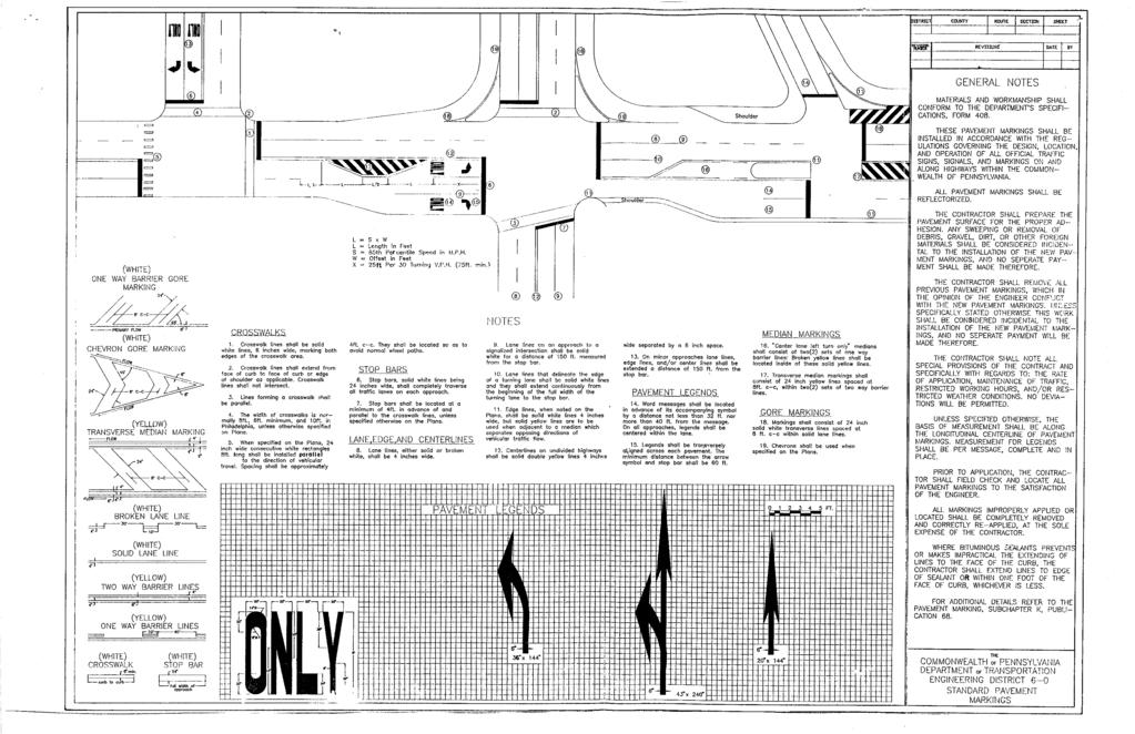
344
Americans with Disabilities Act and Curb Ramps
 Americans with Disabilities Act and Curb Ramps Katherine Smutzer Standards Engineer, INDOT Purdue Road School Wednesday March 9, 2016 Two Items to Remember All curb ramps, sidewalks and sidewalk driveway
RC-67M has been updated to include more details to be consistent with both ADAAG and PROWAG. The following slides discusses the general notes found
 RC-67M has been updated to include more details to be consistent with both ADAAG and PROWAG. The following slides discusses the general notes found on Sheet 1. RC-67M note Construct curb ramps with a minimum
Scenarios. The following slides will show existing pictures that deny access, followed by a retrofitted picture that provides access.
 Scenarios. The following slides will show existing pictures that deny access, followed by a retrofitted picture that provides access. For the following slides assume an overlay project and provide pedestrian
ADA PRESENTATION (CURB RAMPS)
") ADA PRESENTATION (CURB RAMPS) ACECNJ/NJDOT/FHWA DESIGN SUMMIT Warren Howard New Jersey Department of Transportation May 21, 2013 ADA Curb Ramps NJDOT wants curb ramps to be designed & constructed properly
ADA PRESENTATION (CURB RAMPS) ACECNJ/NJDOT/FHWA DESIGN SUMMIT Warren Howard New Jersey Department of Transportation May 21, 2013 ADA Curb Ramps NJDOT wants curb ramps to be designed & constructed properly
DISTRIBUTION: Electronic Recipients List TRANSMITTAL LETTER NO. (17-01) MINNESOTA DEPARTMENT OF TRANSPORTATION. MANUAL: Road Design English Manual
 MINNESOTA DEPARTMENT OF TRANSPORTATION. MANUAL: Road Design English Manual") DISTRIBUTION: Electronic Recipients List MINNESOTA DEPARTMENT OF TRANSPORTATION DEVELOPED BY: Design Standards Unit ISSUED BY: Office of Project Management and Technical Support TRANSMITTAL LETTER NO.
DISTRIBUTION: Electronic Recipients List MINNESOTA DEPARTMENT OF TRANSPORTATION DEVELOPED BY: Design Standards Unit ISSUED BY: Office of Project Management and Technical Support TRANSMITTAL LETTER NO.
Standards vs. Guidelines. Public Right-of Way Accessibility Guidelines (PROWAG)
") www.access-board.gov Public Right-of Way Accessibility Guidelines (PROWAG) Juliet Shoultz, P.E Transportation Systems Engineer US Access Board Standards vs. Guidelines Guidelines are developed by the Access
www.access-board.gov Public Right-of Way Accessibility Guidelines (PROWAG) Juliet Shoultz, P.E Transportation Systems Engineer US Access Board Standards vs. Guidelines Guidelines are developed by the Access
Design Overview. Section 4 Standard Plans for Design. Pedestrian Access Routes. Pedestrian Access Routes. Overview. Cross Slope
 Design Overview Section 4 Standard Plans for Design Fall, 2017 Ann Johnson, PE Services Brady Rutman, SRF Consulting Group Overview Design Basics Recommendations: The Zone System Driveway Crossings Pedestrian
Field guide for Accessible Public Rights-of-Way Edition
 Field guide for Accessible Public Rights-of-Way 2015 Edition BRIEFING MEMO SUBJECT: Department of Justice/Department of Transportation Joint Technical Assistance on Title II of the Americans with Disabilities
Accommodating Pedestrians in the Work Zone
 Accommodating Pedestrians in the Work Zone Guidance for Section C Plan Preparers Some impacts cannot be avoided and those impacts apply to residents, businesses, motorists, and pedestrians alike. However,
ADA on Construction. Guidance for Section C Plan Preparers
 ADA on Construction Guidance for Section C Plan Preparers Some impacts cannot be avoided and those impacts apply to residents, businesses, motorists, and pedestrians alike. However, good planning can minimize
Accessible Sidewalk Requirements
 Accessible Sidewalk Requirements A. Introduction 12A-2 Design Manual Chapter 12 - Sidewalks and Bicycle Facilities 12A - Sidewalks SUDAS and Iowa DOT jointly developed this section based on the July 26,
Field guide for Accessible Public Rights-of-Way Edition
 Field guide for Accessible Public Rights-of-Way 2017 Edition CONTENTS PEDESTRIAN FACILITIES IN THE PUBLIC RIGHT-OF-WAY Pedestrian access routes 3 Components 3 Continuous width 3 Median and pedestrian refuge
ADA Technical Frequently Asked Questions
 ADA Technical Frequently Asked Questions 1. What is the correct way to select and label curb ramp types using the Standard Construction Details?... 2 2. When do you label a curb ramp as modified (e.g.
Americans with Disabilities Act Transition Plan for Public Right-of-Way Improvements
 Americans with Disabilities Act Transition Plan for Public Right-of-Way Improvements Prepared by: Public Works Department Engineering Division October 2015 Table of Contents Section I Introduction.. 3
PROCEDURE FOR ACCOMMODATING PEDESTRIANS IN WORK ZONES FOR CONSTRUCTION AND MAINTENANCE
 PROCEDURE FOR ACCOMMODATING PEDESTRIANS IN WORK ZONES FOR CONSTRUCTION AND MAINTENANCE A.1 STANDARD Measures shall be taken to accommodate pedestrian traffic through and/or around Work Zones for Construction
ADA Operations Contact Info
 Intro ADA Operations Contact Info Todd Grugel ph: 651-366-3531 email: todd.grugel@state.mn.us Joe Zilka ph: 651-366-3311 email: joseph.zilka@state.mn.us Harvey Unruh ph: 651-216-2912 email: harvey.unruh@state.mn.us
ADA & Public Rights of Way
 ADA & Public Rights of Way Overview of Current and Up-coming Requirements FDOT Design Training Expo 2012 Orlando, FL Dean Perkins, RA - ADA Coordinator Florida Department of Transportation Office of Design,
Field Design, Construction and inspection of ADA compliant Curb ramps. Mike Anderson City of Lee s Summit Construction Manager (816)
") Field Design, Construction and inspection of ADA compliant Curb ramps Mike Anderson City of Lee s Summit Construction Manager (816)969-1800 Today s Agenda Definitions & Acronyms Access Board vs. PROWAAC
Field Design, Construction and inspection of ADA compliant Curb ramps Mike Anderson City of Lee s Summit Construction Manager (816)969-1800 Today s Agenda Definitions & Acronyms Access Board vs. PROWAAC
ADA Training Standard Plans
 ADA Training Standard Plans SCREEN READABLE VERSION IS IN THE MAKING AND WILL BE MADE AVAILABLE SOON 2018 MnDOT 2 Standard Plans 2017 Overview Overview PROWAG and Curb Ramp Basics Curb Ramp Types ADA Curb
Department of Public Works Office of Disability Affairs February 23, 2017 Presented by Mark Zwoyer, PE
 ADA Ramp Construction Department of Public Works Office of Disability Affairs February 23, 2017 Presented by Mark Zwoyer, PE Agenda Opening Statements/Welcome PROWAG, ADAAG, INDOT and DPW Standards Inspector
Designing Pedestrian Facilities for Accessibility. Module 3 Curb Ramps & Blended Transitions
 Module 3 & Other Purpose: Allow pedestrians to transition between the street and sidewalks, islands, etc. Typically installed at: Intersections (1 ramp at each end of each crosswalk) Mid-block crossings
Paul Vraney Bureau of Project Development 02/11/2016
 Paul Vraney Bureau of Project Development 02/11/2016 ADA background & alterations definition Design considerations Provide sufficient layout data Curb ramp selection Maximum curb ramp and gutter slopes
CURBSIDE ACTIVITY DESIGN
 5 CURBSIDE ACTIVITY DESIGN This chapter provides design guidance for separated bike lanes adjacent to curbside activities including parking, loading and bus stops. Typical configurations are presented
Appendix T CCMP TRAIL TRAFFIC & TRANSPORTATION DESIGN STANDARD
 Appendix T CCMP 3.3.4 TRAIL TRAFFIC & TRANSPORTATION DESIGN STANDARD 3.3.4 Trail Traffic and Transportation Design Multi-use trails have certain design standards, which vary depending on the agency that
12A Accessible Sidewalk Requirements. 12A Protruding Objects
 TOC Design Manual Chapter 12 - Sidewalks and Bicycle Facilities Table of Contents Table of Contents Chapter 12 - Sidewalks and Bicycle Facilities 12A Sidewalks 12A-1---------------------------------General
CHAPTER 16 PEDESTRIAN FACILITIES DESIGN AND TECHNICAL CRITERIA TABLE OF CONTENTS
 CHAPTER 16 PEDESTRIAN FACILITIES DESIGN AND TECHNICAL CRITERIA TABLE OF CONTENTS Section Title Page 16.1 General... 16-1 16.1.1 AASHTO Reference... 16-1 16.1.2 ADA Requirements... 16-1 16.2 Sidewalks...
DETECTABLE WARNING SURFACES SHALL BE PROVIDED AT THE FOLLOWING LOCATIONS ON PEDESTRIAN ACCESS ROUTES:
 GENERAL NOTES: CURB NOTES: 5'-0" MIN 5'-0" 5'-0" MIN 1. 2. THESE SHEETS ARE IN ACCORDANCE WITH THE AMERICANS WITH DISABILITIES ACT (ADA), AND THE REQUIREMENTS OF THE 2011 PROPOSED ACCESSIBILITY GUIDELINES
Off-road Trails. Guidance
 Off-road Trails Off-road trails are shared use paths located on an independent alignment that provide two-way travel for people walking, bicycling, and other non-motorized users. Trails specifically along
ROUNDABOUTS/TRAFFIC CIRCLES
 GENERAL 1. Description This standard identifies minimum requirements that shall be met for Roundabouts and Neighborhood Traffic Circles in the design and construction of elements for Arlington County Horizontal
Proposed Language as approved by the NCUTCD on June 23, 2011, for new section on Pedestrian Channelizing Devices
 1 2 3 4 5 6 7 8 9 10 11 12 13 14 15 16 17 18 19 20 21 22 23 24 25 26 27 28 29 30 31 32 33 34 35 36 37 38 39 Proposed Language as approved by the NCUTCD on June 23, 2011, for new section on Pedestrian Channelizing
CITY OF PAPILLION, NEBRASKA
 CITY OF PAPILLION, NEBRASKA PROJECT REPORT For TRANSITION PLAN FOR PEDESTRIAN FACILITIES IN THE PUBLIC RIGHT OF WAY April 2010 Introduction The City of Papillion created an initial Transition Plan in the
Appendix C. TRAFFIC CALMING PROGRAM TOOLBOX
 Appendix C. TRAFFIC CALMING PROGRAM TOOLBOX PHASE I...2 Do Not Enter Sign...3 One-Way Sign...4 Turn Prohibition...5 Pavement Markings...6 Speed Monitoring Trailer...7 Neighborhood Speed Watch...8 Police
CHAPTER 8 STAKING SIGNALS AND LIGHTING FIELD GUIDE. 8.1 Staking Traffic Control Signal Systems
 CHAPTER 8 STAKING STAKING Correct staking of traffic control signal or lighting systems is critical to the appropriate placement of system components. 8.1 Traffic Control Signal Systems Locating the components
SECTION TRAFFIC REGULATIONS
 SECTION 01550 TRAFFIC REGULATIONS PART 1 - GENERAL 1.01 OBJECTIVES A. The Contractor shall provide for safe movement of vehicular, bicycle and pedestrian traffic, including persons with disabilities in
ADA Design Overview. Section 2. ADA Design Overview. Pedestrian Access Routes. Pedestrian Access Routes. Overview
 ADA Design Overview Section 2 ADA Design Overview Overview Accessible Pedestrian Signals Alternate Fall, 2017 Ann Johnson, PE Services Brady Rutman, SRF Consulting Group 2 Pedestrian Access Route (PAR)
Driveway Design Criteria
 Design Manual Chapter 5 - Roadway Design 5L - Access Management 5L-4 Driveway Design Criteria A. General For efficient and safe operations, access drives and minor public street intersections can be improved
Roadway Design Manual
 Roadway Design Manual Manual Notice Archive by Texas Department of Transportation (512) 302-2453 all rights reserved Manual Notice 2009-1 From: Manual: Mark A. Marek, P.E Roadway Design Manual Effective
12A Accessible Sidewalk Requirements
 TOC Design Manual Chapter 12 - Sidewalks and Bicycle Facilities Table of Contents Table of Contents Chapter 12 - Sidewalks and Bicycle Facilities 12A Sidewalks 12A-1---------------------------------General
700 Multi-Modal Considerations
 700 Multi-Modal Considerations Table of Contents 701 Railroads... 7-1 701.1 Background... 7-1 701.2 Crossing At-Grade... 7-1 701.2.1 General... 7-1 701.2.2 Railroad Parallel to Highway... 7-1 701.3 Lateral
A. Arlington County Master Transportation Plan Pedestrian Element B. Arlington County Horizontal Standards H-3.1 Driveway Entrances
 GENERAL 1. Description This standard identifies minimum requirements that shall be met for all accessible ramps in the design and construction of elements for Arlington County Horizontal Design Standards.
ADA Training Accessible Pedestrian Signal (APS) 2018 MnDOT
 2018 MnDOT") ADA Training Accessible Pedestrian Signal (APS) 2018 MnDOT APS and ADA APS is not currently an ADA Standard and is provided at the discretion of the Title II entity APS is recognized in the MnMUTCD, but
ADA Training Accessible Pedestrian Signal (APS) 2018 MnDOT APS and ADA APS is not currently an ADA Standard and is provided at the discretion of the Title II entity APS is recognized in the MnMUTCD, but
City of Roseville Section 13 Design Standards. _Bikeways January 2016 SECTION 13 BIKEWAYS
 SECTION 13 BIKEWAYS 13-1 GENERAL The City of Roseville bikeway standards are designed to insure that transportation and recreational bikeways are constructed in a manner that would provide a safe and comfortable
CHAPTER 1 STANDARD PRACTICES
 CHAPTER 1 STANDARD PRACTICES OBJECTIVES 1) Functions and Limitations 2) Standardization of Application 3) Materials 4) Colors 5) Widths and Patterns of Longitudinal Pavement Marking Lines 6) General Principles
Portland Peninsula Sidewalk and Ramp Inventory
 Portland Peninsula Sidewalk and Ramp Inventory Conducted June and July of 2008 By Anne Krikorian and Ryan Carmichael Performed under the authority of: Greater Portland Council of Governments And with the
ROADWAY AND PARKING DETAILS TYPICAL STREET SECTIONS PRINCIPAL ARTERIAL NOT TO SCALE
 NOTES: O:\Division Information\Engineering\Documents\Engineering and Construction\COMMERCE CITY\CAD files\2016 Updated Files\307-01 thru 307-09 (Roadway & Parking Typical Sections).dwg 6' SIDEWALK MAY
Appendix A: Crosswalk Policy
 Appendix A: Crosswalk Policy Appendix A: Crosswalk Policy Introduction This citywide Crosswalk Policy is aimed at improving pedestrian safety and enhancing pedestrian mobility by providing a framework
ADA COMPLIANCE IN PUBLIC RIGHTS-OF-WAY. Ali Everett Accessibility Issues Coordinator City of Pasadena January 25, 2018
 ADA COMPLIANCE IN PUBLIC RIGHTS-OF-WAY Ali Everett Accessibility Issues Coordinator City of Pasadena January 25, 2018 Americans with Disabilities Act CIVIL RIGHTS LAW BUILT ON THE PRINCIPLES OF: EQUAL
Roadway Design Manual
 Roadway Design Manual Revised December 2013 2013 by Texas Department of Transportation (512) 302-2453 all rights reserved Manual Notice 2013-1 From: Manual: Mark A. Marek, P.E Roadway Design Manual Effective
Virginia Department of Transporta on Work Zone Pedestrian and Bicycle Guidance
 Virginia Department of Transporta on Work Zone Pedestrian and Bicycle Guidance May 1, 2016 Table of Contents Page Preface...ii 1. Introduction...1 ADA Requirements...1 Special Pedestrian Populations...2
ATTACHMENT NO. 11. RRLRT No. 2. Railroad / Light Rail Transit Technical Committee TECHNICAL COMMITTEE: Busway Grade Crossings STATUS/DATE OF ACTION
 ATTACHMENT NO. 11 RRLRT No. 2 TECHNICAL COMMITTEE: TOPIC: Railroad / Light Rail Transit Technical Committee Busway Grade Crossings STATUS/DATE OF ACTION RRLRT TC Draft: 06/23/2011 RRLRT TC Approval: 06/27/2014
Designing Pedestrian Facilities for Accessibility. Module 8 Maintenance of Pedestrian Facilities and Alternate Pedestrian Access Routes in Work Zones
 Designing Pedestrian Facilities for Accessibility Module 8 Maintenance of Pedestrian Facilities and Alternate Pedestrian Access Routes in s Maintenance of Accessible Features Title II (28 CFR 35.133(a))
TRANSMITTAL LETTER. Revision to Publication 149, Chapter 20 (Criteria for the Design of Traffic Signal Supports) - March 2009 Edition
 - March 2009 Edition") OS-299 (7-08) TRANSMITTAL LETTER PUBLICATION: Publication 149 - Traffic Signal Design Handbook DATE: 10/14/10 SUBJECT: Revision to Publication 149, Chapter 20 (Criteria for the Design of Traffic Signal
OS-299 (7-08) TRANSMITTAL LETTER PUBLICATION: Publication 149 - Traffic Signal Design Handbook DATE: 10/14/10 SUBJECT: Revision to Publication 149, Chapter 20 (Criteria for the Design of Traffic Signal
ADA TRANSITION PLAN. For
 Page 1 of 7 ADA TRANSITION PLAN For PUBLIC WORKS DEPARTMENT 121 SW Port St. Lucie Boulevard Port St. Lucie, FL 34983 Phone: 772-871-5177 Website: www.cityofpsl.com September 2018 Table of Contents 1) Introduction
Town of Mooresville, North Carolina Neighborhood Traffic Calming and Control Device Policy
 Town of Mooresville, North Carolina Neighborhood Traffic Calming and Control Device Policy Adopted January 6, 2014 Town of Mooresville Development Services Department TOWN OF MOORESVILLE NEIGHBORHOOD TRAFFIC
PLACEMENT OF SIGNS RECOMMENDED PRACTICES SUB-SECTION
 Page 1 of 6 RECOMMENDED PRACTICES PART SECTION SUB-SECTION HIGHWAY SIGNS GENERAL General Proper positioning of signs is an important element in the overall control of traffic within a roadway network.
Curb Ramp Guidelines. October Version 1.0
 Curb Ramp Guidelines October 2010 Version 1.0 Table of Contents INTRODUCTION... 3 DEFINITIONS... 3 BASIC CURB RAMP COMPONENTS... 4 PEDESTRIAN RAMP TYPES... 6 Selecting ramp types... 7 PERPENDICULAR CURB
PROWAG/ADAAG Standards Guidance For Temporary Pedestrian Access Route (TPAR) Facilities and Devices
 Facilities and Devices") INTRODUCTION: PROWAG/ADAAG Standards Guidance For Temporary Pedestrian Access Route (TPAR) Facilities and Devices Minnesota Department of Transportation DRAFT Document DRAFT This document was developed
INTRODUCTION: PROWAG/ADAAG Standards Guidance For Temporary Pedestrian Access Route (TPAR) Facilities and Devices Minnesota Department of Transportation DRAFT Document DRAFT This document was developed
General Design Factors
 Chapter 3: 3-1.0 Introduction General Design Factors Mn/DOT s goals include encouraging and accommodating safe bicycling. From a design perspective, these goals are achieved by first having an understanding
Route 47 (North Main Street) Reconstruction
 Reconstruction") TOWN OF SUNDERLAND Route 47 (North Main Street) Reconstruction Presented by Lou Rabito, P.E. Presented to Town of Sunderland June 11, 2018 Project Overview MassDOT Project No. 607245 Resurfacing and Related
TOWN OF SUNDERLAND Route 47 (North Main Street) Reconstruction Presented by Lou Rabito, P.E. Presented to Town of Sunderland June 11, 2018 Project Overview MassDOT Project No. 607245 Resurfacing and Related
Traffic Engineering and Highway Safety Bulletin Accessibility Compliance for Military Installations
 Traffic Engineering and Highway Safety Bulletin 12-01 Accessibility Compliance for Military Installations February 2012 Did You Know? More than 54 million Americans, almost 20 percent of the U.S. population,
APPENDIX A: Complete Streets Checklist DRAFT NOVEMBER 2016
 APPENDIX A: Complete Streets Checklist DRAFT NOVEMBER 2016 Complete Streets Checklist MetroPlan Orlando s Complete Streets Checklist is an internal planning tool for staff to further implementation of
MEMORANDUM. Date: 9/13/2016. Citywide Crosswalk Policy
 MEMORANDUM Date: 9/13/2016 Re: Citywide Crosswalk Policy Foreword Through the s Circulation Element and Complete Streets Policy, it is the City s goal to promote walking trips and provide safe facilities
APPENDIX F DESIGN STANDARDS REVIEW SUMMARIES AND REDLINES
 APPENDIX F DESIGN STANDARDS REVIEW SUMMARIES AND REDLINES 092775000 Carson City ADA Transition Plan 2015-03-25 Carson City ADA Transition Plan.docx March 2015 APPENDIX This page intentionally left blank.
Preparing a Curb Ramp Project. December 15, 2010
 Preparing a Curb Ramp Project December 15, 2010 3 Tiers of Project Types Non-Signalized Curb Ramp Reconstruction - Typically utilizing standard plans and identifying ramp types at each quadrant Signalized
Access Management Standards
 Access Management Standards Section 1: Application of Access Standards This chapter describes the Department's access management standards for access connections on the county roadway system. The standards
ADA Operations Contact Info
 Intro ADA Operations Contact Info Todd Grugel ph: 651-366-3531 email: todd.grugel@state.mn.us Joe Zilka ph: 651-366-3311 email: joseph.zilka@state.mn.us Harvey Unruh ph: 651-216-2912 email: harvey.unruh@state.mn.us
Bases, Ballasts, and Paving
 Sections Included In This Standard: 1.1 Paving and Surfacing 1.2 Protection of the Work 1.3 Repair of Pavement 1.4 Pavement Marking 1.1 PAVING AND SURFACING A. DESIGN REQUIREMENTS 1. Applicable Design
Designing Accessible Traffic Signals
 Designing Accessible Traffic Signals Adam Allen, P.E., TSOS ADA Compliance Crackdown Draft Public Rights of Way Accessibility Guidelines (PROWAG) 2009 Manual on Uniform Traffic Control Devices (MUTCD)
INDOT Complete Streets Guideline & Policy
 INDOT Complete Streets Guideline & Policy INTRODUCTION The Complete Streets guidelines build upon multiple efforts and promote a multimodal transportation system that is integrated and sustains land use
PEDESTRIAN CROSSING TREATMENTS
 PEDESTRIAN CROSSING TREATMENTS BEST PRACTICES Presented by: Doug Enderson, P.E., PTOE Cody Salo, P.E. 1 PRESENTER INTRODUCTIONS Doug Enderson, P.E., PTOE Ped Crossing Experience: ADA Design-Build ADA Inventory
2017 Temporary traffic control guidelines for pedestrians. v.2
 2017 Temporary traffic control guidelines for pedestrians v.2 Temporary Traffic Control Guidelines for Pedestrians (2017) The safety and mobility of pedestrians, cyclists and motorists must be considered
City of Margate, Florida. Neighborhood Traffic Management Manual
 City of Margate, Florida Neighborhood Traffic Management Manual Table of Contents Page No. I. INTRODUCTION... 1 II. TRAFFIC CALMING REQUEST AND PROCESSING PROCEDURES... 2 1. COMPLETE AND SUBMIT PROJECT
Broad Street Bicycle Boulevard Design Guidelines
 Broad Street Bicycle Boulevard Design Guidelines Building from the strategies introduced in the 2013 Bicycle Transportation Plan and community input received thus far, City Transportation Staff have identified
CHAPTER 2G. PREFERENTIAL AND MANAGED LANE SIGNS
 2011 Edition - Revision 2 Page 275 Section 2G.01 Scope CHAPTER 2G. PREFERENTIAL AND MANAGED LANE SIGNS 01 Preferential lanes are lanes designated for special traffic uses such as high-occupancy vehicles
10.0 CURB EXTENSIONS GUIDELINE
 10.0 CURB EXTENSIONS GUIDELINE Road Engineering Design Guidelines Version 1.0 March 2017 City of Toronto, Transportation Services City of Toronto Page 0 Background In early 2014, Transportation Services
2014 FHWA Aging Road User Handbook. Recommendations to Accommodate Aging Pedestrians. Lifesaver National Conference. What is the Handbook?
 2014 FHWA Aging Road User Handbook Recommendations to Accommodate Aging Pedestrians Lifesaver National Conference March 17, 2015 Revised June 2014 1 What is the Handbook? 1998 1st Edition 2001 2nd Edition
Considerations in the Review and Approval of a Driveway in Your Jurisdiction
 Considerations in the Review and Approval of a Driveway in Your Jurisdiction So, are you the person at your agency who reviews and approves new driveways? Or, perhaps you are part of the TEAM of people
COMPLETE STREETS DURING CONSTRUCTION
 COMPLETE STREETS DURING CONSTRUCTION MAINTAINING ACCESSIBILITY FOR ALL Presented by Robbie Burgess, P.E., PTOE Associate Principal Construction Services Manager Howard Stein Hudson rburgess@hshassoc.com
Steps to Conducting a Complete Streets Assessment
 Steps to Conducting a Complete Streets Assessment Familiarize yourself with Complete Streets Read through the Complete Streets Assessment Guidelines. This will give you an idea of what Complete Streets
STANDARD SPECIFICATIONS FOR PUBLIC WORKS CONSTRUCTION CITY OF MANITOWOC, WISCONSIN SECTION 900 TRAFFIC CONTROL
 SECTION 900 TRAFFIC CONTROL STANDARD SPECIFICATIONS FOR PUBLIC WORKS CONSTRUCTION CITY OF MANITOWOC, WISCONSIN SECTION 900 TRAFFIC CONTROL Section Number Title 901 GENERAL 902 MATERIALS, EQUIPMENT, AND
City of East Grand Forks. ADA Transition Plan. Inventory Manual. June, 2018 DRAFT
 ADA Transition Plan City of East Grand Forks Inventory Manual June, 2018 DRAFT ADA Transition Plan City of East Grand Forks Inventory Manual Client City of East Grand Forks Consultant Team SRF Consulting
October 2004 REVISIONS (2) SUPERELEVATION DEVELOPMENT 11.3(2)
 SUPERELEVATION DEVELOPMENT 11.3(2)") October 2004 REVISIONS (2) Chapter 11 HORIZONTAL ALIGNMENT SUPERELEVATION DEVELOPMENT 11.3(2) Chapter 12 VERTICAL ALIGNMENT VERTICAL CURVES PASSING SIGHT DISTANCE 12.5(2) VERTICAL CURVES STOPPING SIGHT
October 2004 REVISIONS (2) Chapter 11 HORIZONTAL ALIGNMENT SUPERELEVATION DEVELOPMENT 11.3(2) Chapter 12 VERTICAL ALIGNMENT VERTICAL CURVES PASSING SIGHT DISTANCE 12.5(2) VERTICAL CURVES STOPPING SIGHT
Designing Pedestrian Facilities for Accessibility
 Designing Pedestrian Facilities for Accessibility Laws, Regulations and Pedestrian Characteristics John H. Miller, PE - FHWA ACECNJ/NJDOT/FHWA 2013 DESIGN SUMMIT Legal Background Architectural Barriers
 COMPLETE STREETS CHECKLIST City of Philadelphia The City of Philadelphia's Complete Streets policies are designed ensure that city streets are safe, comfortable and convenient for people of all ages and
MUTCD Part 6: Temporary Traffic Control
 MUTCD Part 6: Temporary Traffic Control OMUTCD English units are preferred. OHIO MANUAL OF UNIFORM TRAFFIC CONTROL DEVICES TABLE OF CONTENTS PREFACE INTRODUCTION TABLE OF CONTENTS PART 1. GENERAL Chapter
Please feel free to print this PDF form. The document is below. Please scroll down.
 ADA Accessibility Guidelines: Detectable Warnings Please feel free to print this PDF form. The document is below. Please scroll down. For more relevant information, please visit the Armor Tile website.
WYDOT DESIGN GUIDES. Guide for. Non-NHS State Highways
 WYDOT DESIGN GUIDES Guide for Non-NHS State Highways 2014 GUIDE FOR Non-NATIONAL HIGHWAY SYSTEM (Non-NHS) STATE HIGHWAYS PRESERVATION REHABILITATION RECONSTRUCTION INTRODUCTION This Guide is directed to
STAKING TRAFFIC CONTROL SIGNAL SYSTEMS
 Locating the components of a traffic control signal is not an exact science; many factors influence the location of the components. These factors include: lane widths, radii, pedestrian curb ramp requirements,
Figure 3B-1. Examples of Two-Lane, Two-Way Marking Applications
 Figure 3B-1. Examples of Two-Lane, Two-Way Marking Applications A - Typical two-lane, two-way marking with passing permitted in both directions B - Typical two-lane, two-way marking with no-passing zones
Traffic Control Inspection Checklist Segment:
 Traffic Control Inspection Checklist Segment: Simon Contractors Simon Contractors Originator: Description Reviewed by: Initials Date Distribution: Traffic Quality Manager, Site Assistant Traffic Manager
INDEX. Geometric Design Guide for Canadian Roads INDEX
 Acceleration lane, see Lanes, Acceleration Access, 8.1 Access Management and Functional Classification 8.2 Access Management by Design Classification 8.3 Access Configuration 8.4 Building Set-Back Guidelines
First Annual Colorado Chapter Conference Englewood, CO. Accessible Pedestrian Facilities in the
 First Annual Colorado Chapter Conference Englewood, CO Accessible Pedestrian Facilities in the Public Right-of-Way October 14 th, 2014 Mode of Transportation Photo: Mountain Waters Rafting, LLC Session
REVOCABLE PERMIT FOR STREET BANNER APPLICATION PACKAGE
 Development Engineering 300 Richards Blvd., 3rd Floor Sacramento, CA 95811 Engineering Services Division REVOCABLE PERMIT FOR STREET BANNER APPLICATION PACKAGE Phone: 916-808-8300 Fax: 916-808-1984 Preparation
DESIGN CRITERIA DIVISION 4900 TRAFFIC SIGNALS
 DESIGN CRITERIA DIVISION 4900 TRAFFIC SIGNALS 4901 GENERAL: These criteria shall be adhered to for the design of all publiclyfinanced or privately-financed traffic signal systems to be installed in the
RAILWAY LEVEL CROSSING CHECKLIST Road Safety Review of Railway Crossings
 RAILWAY LEVEL CROSSING CHECKLIST Road Safety Review of Railway Crossings Location: Crossing No. Date of On-Site Inspection: (Day) / / (Night) / / Weather: CHECKLIST 5. - GENERAL TOPICS Level of control
ADA TRANSITION PLAN 2013
 ADA TRANSITION PLAN 2013 TABLE OF CONTENTS Contents Introduction 1 Purpose 2 Identified Obstacles to the Public Right of Way 3 Criteria for Determining Impediments at Village Facilities 4 Removing Barriers
Off-Road Facilities Part 1: Shared Use Path Design
 Off-Road Facilities Part 1: Shared Use Path Design Presentation by: Eric Mongelli, P.E. Tom Huber October 9, 2012 FOLLOW THE CONVERSATION ON TWITTER Toole Design Group is live tweeting this webinar @tooledesign
Gordon Proctor Director Policy on Accommodating Bicycle and Pedestrian Travel on ODOT Owned or Maintained Facilities
 Approved: Policy: 20-004(P) Responsible Office: Planning Gordon Proctor Director Policy on Accommodating Bicycle and Pedestrian Travel on ODOT Owned or Maintained Facilities I. POLICY STATEMENT: This policy
CHAPTER 1 GENERAL DESIGN
 CHAPTER 1 GENERAL DESIGN 1.0 INTRODUCTION The purpose of this Manual is to provide its users with the current, uniform procedures and guidelines for the application and design of safe, convenient, efficient
Shared Use Path Design
 12B-2 Design Manual Chapter 12 - Sidewalks and Bicycle Facilities 12B - Bicycle Facilities Shared Use Path Design A. Accessible Shared Use Path Design 1. General: Applicable portions from the following