Handlebars Stem Bell Headset Headlight Mudguard Fork Front brake Tires Wheels Bottom bracket Pedals Chain Rear derailleur Rear light Reflector.
|
|
|
- Ralph Floyd
- 6 years ago
- Views:
Transcription

1

2 Handlebars Stem Bell Headset Headlight Mudguard Fork Front brake Tires Wheels Bottom bracket Pedals Chain Rear derailleur Rear light Reflector Rack Seat Frame The Bycicle and its components

3 Contents Congratulations on your new DHM bicycle! As with all DHM bicycles, it is of the absolute highest quality. To start with, we d like to provide you with some important information about your new DHM bicycle. This could help you make the most of its benefits and avoid any possible risks. Please read this instruction manual carefully and keep it for your future reference. Contents Important note before reading 3 Legal regulations 4 Complying with regulations 4 Instructions relating to your own safety 4 Before the first ride 5 Before and after every ride 5 Adjusting the bicycle to the rider 5 Height of the frame, seat and handlebars 5 Quick releases 5 Setting up the seat height 6 Setting up the handlebar position 6 Components of the bicycle 7 Bottom bracket and cranks 7 Pedals 7 Gears and chain 7 Operating chain gears 7 Brakes 7 Disc brakes 8 Headset 8 Frame 8 Fork 8 Frames with rear suspension 9 Wheels, tires, air pressure, valves 9 Lights 10 Add-ons 10 Rack 10 Mudguards 10 Parking stands 11 Technology 12 Checks and inspections 31 Instructions for care and maintenance 31 Screws and torque wrenches 31 Care and maintenance 31 Fixing a flat tire 32 Carbon components 33 Parts subject to wear 33 Technical information 33 Warranty 34 Interesting cycling links 35 What to consider when riding a pedelec 35 Important note before reading This instruction manual contains three types of pointers one providing important information about your new bicycle and how to use it, a second referring to possible damage to property and the environment, and a third type warning against potential falls and serious damage, including physical injury. These break down as follows: Information: This symbol provides information about how to use the product or highlights specific parts of the instruction manual that are particularly important. Warning: This symbol is aimed at warning you against improper use that could result in damage to property or the environment. Danger: This symbol indicates possible dangers to your health and life that could arise if specific actions are not taken or corresponding regulations adhered to. Your bicycle was fully assembled and set up before you received it. If this was not the case then please contact a specialist retailer to ensure that this work is completed. It is assumed that users of this product have a basic and sufficient knowledge of how to use bicycles. Everyone that: uses repairs or services cleans or disposes of this bicycle has to understand and take note of the content and meanings of this instruction manual. If you have any further questions or have not quite understood certain points, you should contact a specialist bicycle retailer for your own safety. All information contained in this instruction manual relates to the design, technology as well as care and maintenance of your bicycle. Please take note of this information, as much of it is relevant to safety. Failure to consider this information can cause accidents, which could even result in serious accidents and damage to property. As a bicycle s technology is highly complex, we have chosen to only describe the most important points. For more specific technical details, please refer to the enclosed notes and instructions from the respective manufacturers of the individual components used. If you are unsure about a particular point, please contact your specialist retailer. Firstly, here are a few important pointers as to the rider s person: Always wear a suitable bicycle helmet adjusted to fit your head and use this for every ride. Always wear bright clothing or sportswear with reflective elements when you ride. This is vital so that other people can SEE YOU. Always wear tight clothing on your lower body, and trouser clips if required. Your shoes should be grippy and have stiff soles. 3
4 Legal regulations Legal regulations Before riding your bicycle on the road, you should inform yourself about the applicable national regulations in your specific country. In Germany, the applicable laws are the StVZO (German Road Traffic Regulation) and the STVO (German Highway Code). In Switzerland, the applicable regulations are outlined in the guidelines for the technical requirements of road traffic in articles 213 to 218 (Verordnungen über die technischen Anforderungen an Strassenfahr zeuge). Ensure that your bicycle is truly in a roadworthy condition before every ride, and that the brakes are optimally set up and the bell and light system correspond with the StVZO (German Road Traffic Regulations). This includes white front and rear lights powered by a fixed dynamo (6V, 3W), a clearly audible bell and reflectors. The reflectors have to be set up as follows: front white, large, may be integrated into the light; rear two red reflectors, one may be integrated into the rear light; wheels with two yellow reflectors per wheel, alternatively white reflecting rings in the tyre, rims or spokes; peddles with one yellow reflector per peddle one reflecting forwards and one reflecting backwards. Only racing bicycles weighing less than 11 kg are allowed to use battery-powered head and rear lights, and these must be carried with the bicycle at all times. All other bicycles have to use dynamodriven lights and each lighting system has to carry a stamp of official approval. Here, the StVZO applies. When making technical changes to the components on your bicycle, please note that electrical parts may only be replaced with type-tested components. Participating in public road traffic in Austria requires riders to comply with Act 146 / the so-called bicycle act (Fahrradverordnung). This is outlined in the Austrian Federal Law Gazette (Bundesgesetzblatt). Please ensure that before every ride your bicycle is in a roadworthy state, that the brakes are perfectly set up and that the bell and light system comply with the StVZO. Only racing bicycles weighing less than 11 kg are allowed to use battery-powered head and rear lights, and these must be carried with the bicycle at all times. All other cyclists have to use dynamo-powered lighting systems, with every system having to hold the national seal of approval. The StVZO is applicable here. When making changes to the components on your bicycle, please note that electrical parts may only be replaced with type-tested components. Complying with regulations Usually, bicycles are intended for transporting one person at a time. If you are planning to transport additional people or baggage then the regulations of the StVO apply. Here there are specific weight restrictions depending on the size and type of the bicycle as well as the location of the rack (see technical information ). If they are set up as stipulated by the StVZO, Trekking bikes / ATBs are allowed to be ridden on public roads, paved trails and unsurfaced routes City, touring, sports, childrens and youth bikes can be used on public roads and paved trails Racing bikes/fitness bikes can be used on public roads for training purposes. They may only be ridden on asphalt surfaces! Mountain bikes may be used off-road and on non-paved tracks. They may NOT be used in races or for downhill! These types of bicycles are only permitted on public roads after the compulsory equipment has been fitted! The guidelines laid down in the StVO and StVZO do not generally apply when using your bicycle in competitions. However, all guarantees and liability regulations only apply as long as the bicycle is being used in accordance with its conditions of use and safety guidelines. Otherwise all liability for the manufacturer and retailer is nullified. This includes carrying too much weight on the bicycle, not properly repairing damage, using the bicycle off-road and in competition as well as all uses not in line with the conditions of use. This always includes: Carrying too much weight Improper repairs of damage Use in competitions, as well as not adhering to the conditions of use and maintenance, doing jumps, riding down steps and anything else that places extreme stress on the bicycle. Instructions relating to your own safety Every type of bicycle has a different load capacity which is listed in the Technical information chapter. If a bicycle is subjected to excess load, this can lead to breaks in the handlebars, fork or frame, for example. The maximum permitted load for the rack is usually stated on the rack itself. If this is not the case, the maximum permitted amount for your rack will be listed in the Technical information chapter. Not all bicycles are suitable for installing children s seats or bicycle trailers your specialist retailer can advise you in this area. In particular, frames and components made of carbon are completely unsuited to carrying this additional weight! Bent or damaged components have to be replaced; they could contain hairline cracks or be broken following a fall. Continuing to use them could cause serious injury. Different types of rims (carbon, aluminum) require different types of brake pads to work efficiently. Otherwise this can cause accidents. Please take your bicycle to a specialist to carry out repairs, servicing and setting up parts of the bicycle. As a rule, the following applies: You should ride carefully in wet conditions, particularly those covered in wet leaves in autumn. Brake earlier and ride slower as the braking distance is considerably longer in these conditions. Do not only use your lights when its dark, you should also use your lights at twilight and in foggy or rainy conditions. You can see and be seen better. Do not overestimate yourself: your speed should match your abilities both on public roads as well as off-road. The setup and functionality of the bicycle could change during transport despite multiple checks being carried out during production and the final post-production check. Therefore, check the following before the first ride: Screws, bolts and pedals are all secure Stem, handlebars and seat post are all safely secured and adhere to the minimum insertion length Test the setup of the brakes and their effectiveness Check that the wheels and quick releases are secure Check that the suspension components are working properly Gears and lights Air pressure and tires Check the quick release locks before every ride, even if your bicycle was only left unattended for a short period of time! Generally, a bicycle will change most in the first 100 kilometers; the spokes will bed in, the brake cables and gear cables settle into the housings and the bearings are broken in. Therefore, it is important that you have your first inspection carried out by a specialist retailer after kilometers or 4 6 weeks. This should encompass: 4
 Checking the headset, brakes, gears and suspension parts, adjusting them where necessary When working on your bicycle, please ensure in particular that all")
 and this work should be carried out using a torque wrench. The best sort of torque wrench for this is one that clicks when it reaches the prescribed torque.")
5 Before the first ride Checking the wheels, which should be tensioned and trued as required Oiling the chain and gear system Checking that screws, bolts and quick releases are secure Checking the torques (pedals, cranks, handlebars, seat) Checking the headset, brakes, gears and suspension parts, adjusting them where necessary When working on your bicycle, please ensure in particular that all screws that are key to safety are secured with the correct torque. The required torque is printed on many components. This amount is stated in Newton meters (Nm) and this work should be carried out using a torque wrench. The best sort of torque wrench for this is one that clicks when it reaches the prescribed torque. Otherwise screws can snap or break. If you don t own a torque wrench then you should always leave this work up to a specialist retailer! A table listing the most important torques for bolted connections is provided in the Technical information chapter. Before the first ride Please ensure that the bicycle is ready for use and adjusted to fit your body. That means: adjusting the positioning and mounting of the seat and handlebars, assembling and setting up the brakes and ensuring the wheels are properly fastened in place. Move the handlebars and stem into a safe and comfortable position for you. Please refer to page 6 for instructions on how to adjust the handlebars. Adjust the seat to a safe and comfortable position for you. Please refer to page 5 for instructions on how to adjust the seat. Please ensure that the brakes are always within easy reach and that you understand the position and functionality of the brake handles on both the left and the right! Ensure that you know which lever operates which brake! Modern braking systems might be more powerful than those that you have used before. Before and after every ride Check that the: Lights and bell are working and safely secured Brakes are working safely and are properly secured Tires are free of foreign objects and damage, and that the rims are not damaged and run true (particularly after riding off road) Suspension components are working properly and are safely mounted Gears are working properly and are secured All quick releases are secured Frame and fork are not misshapen or damaged If you are unsure of whether your bicycle is in a sound technical state, take it to a specialist retailer to be checked! Adjusting the bicycle to the rider Height of the frame, seat and handlebars A bicycle has to fit your physical dimensions for you to feel comfortable on it! The frame size of your bicycle is determined according to your size. You should consult a specialist retailer when selecting your frame. Your comfort and ability to perform on the bicycle are ultimately and largely dictated by setting up the perfect seating position. Please ensure you read the instruction manual supplied by the component manufacturers for each component. Only use the correct torque for tightening the important bolted connections. Please adhere to the prescribed torque of each bolt! Please get to know the brakes on a safe piece of land before setting off on your first ride with the bicycle! Please ensure that the wheels are safely fastened in the frame and fork. Check that the quick release for the seat is tight as well as all important nuts and bolts! The Technology chapter contains instructions on how to safely use the quick releases, while Technical information contains a table with the torque of important nuts and bolts. Check the air pressure in the tires. If you place your thumb on the pumped up tire, you should not be able to bend the tire very much, even when a lot of force is exerted. Check the tires and rims for damage. If you can see cracks, holes or tears then do not ride the bicycle! Check: The frame and fork must not be misshapen or damaged. This is done as follows: The height and tilt of the seat are important. The seat should usually be set up to be level (parallel to the ground) or tilting slightly backwards. However, you must find the position that is most comfortable for you, which comes with experience. Your specialist retailer will be happy to help you set up a good seat position. You are able to adjust the height of the seat post with the seat bolt or quick release. Quick releases Use quick releases with great care; they are key to your safety on the bicycle and are located on the front wheel, rear wheel and possibly even the seat tube. Tilt of the seat If you have doubts about whether your bicycle is in perfect technical condition, do not ride it. Please have it checked by a specialist retailer! Aside from the locking nut, which allows you to regulate the clamping force, the quick release also has a clamping lever, which converts the closing movement into clamping force. To open the quick release, the clamping lever has to be opened 180 degrees, revealing the word Open. To close possible positions the release, simply close the lever 180 back to its original position, of quick releases allowing you to read the word Close. A good gauge for measuring if the wheel is safely clamped is if you can only close the clamping lever with the balls of your hands with a moderate amount of pressure. You should then feel an 5


6 Setting up the seat height increasing amount of resistance after closing the lever about half way. If the component is not properly or insufficiently fastened, turn the opened quick release lever clockwise by half a revolution. Then close the lever and test if the wheel is now tightly attached. If the component is not tight or securely tightened enough, then open the quick release lever and rotate it clockwise by 180 degrees. Then close the quick release lever and test the component again for tightness. For example: Grip the front and rear wheels on the tyres and shake them strongly in a lateral motion. The wheels should remain tightly in place. When closed, quick release levers should be flat against the frame, fork or seat post and should always point backwards! This ensures that they cannot be opened through contact during riding. More information about quick releases is provided in the Technology chapter. Check that all quick releases are properly fastened before every ride! Setting up the seat height There is a simple process to test the height of your seat: Sit on the seat and the heel of your fully stretch leg should sit on the pedal at the bottom of its cycle. In contrast, with the balls of your feet on the pedals, your leg should be slightly bent when the pedals are at their lowest point. Tilt of the seat Horizontal seat position When adjusting the height of the seat, you must leave a minimum insertion length of 7.5 cm (10 cm for longer seat tubes that stick out above the level of the top tube). This minimum insertion length is usually clearly indicated, and it is very important for your safety! The seat clamping bolt is either opened anti-clockwise and closed clockwise with an allen key; or it is attached to a quick release mechanism. The same applies when adjusting the tilt of the seat. Please ensure you use the correct torque for the bolts! Maximum insertion length Seat clamping screw Quick release Seat quick release Setting up the handlebar position When setting up or adjusting the position of your handlebars, it is vital to observe the 6.5 cm minimum insertion length of the handlebar stem or observe the STOP marking on the stem otherwise the stem could be unstable. With conventional handlebar stems, you first have to loosen the stem spindle with an allen key anticlockwise, while holding the front wheel between your knees. Twist the stem shaft back and forth or knock on the spindle with a plastic mallet from above until the clamping screw is released. Then adjust Stem the stem to the desired height and orient the handlebars so that the stem forms a right angle with the frame. Then tighten the spindle clockwise with the allen key (take note of the correct torque!). The height of A-head systems should always be adjusted by specialist retailers. The same applies for setting up adjustable stems. They have to be adjusted by specialists. Adjusting this part of the bicycle incorrectly could lead to very serious falls and injury! The alignment of the handlebars in their horizontal position can be changed by loosening the lock bolts on the front side of the stem in a clockwise direction, adjusting the position of the bar as desired and then tightening the screw back to the prescribed torque. Please ensure that the handlebars are exactly in the middle of the stem. If your bicycle is equipped with an adjustable stem, you can adjust the height and distance to your handlebars as you wish. This is done by changing the tilt of the stem. To do this, loosen the allen bolt located on the side of the stem by turning it several times with an allen key. You should now notice that you are able to move the stem. Please ensure that you do not turn the screw so much that the individual parts of the stem fall apart. When the internal locking system is loose enough, you should be able to move the stem upwards and downwards. Move the handlebars into the desired position and tighten the allen screw again. The required torque is stated on the side of the stem. Please note that this process also twists the handlebars. Now you have to adjust the handlebars into a position in the stem in which you can easily and safely operate that brakes and gears! A brief instruction on how to do this is outlined in the section Adjusting the bicycle to the rider. A-Head stem Stem cap A-Head stem Suspension seat posts, which are designed to take some pressure off the spine, should be set up by your specialist retailer. The handlebar assembly consists of the stem, the handlebar itself, controls and the headset. The position of these components has a great influence on your ultimate seating position and the resultant posture. Ultimately, the seating position is governed by the height difference between the handlebars and the seat. Low handlebars increase the pressure on the upper body, arms and wrists, while higher handlebars put more load on the spine. The best way to find the best setup for you is with the help of a partner who holds the bicycle in place while you bend your upper body forward bit by bit while sitting on the bicycle and stretching your hands towards the handlebars. Specialist retailers can also be a good source of advice here too. 6


.")


7 Components of the bicycle Components of the bicycle Bottom bracket and cranks The bottom bracket, crankset, gearside, chain and pedals form the bicycle s drive train. The bottom bracket consists of an axle, ball bearing, sealing rings and bearing shells. These are contained in a unit known as a sealed bottom bracket. This is enclosed and set up in the factory in such a way that it requires no maintenance. It is important that the cranks and bottom bracket do not exhibit any play and are secure; these have to be regularly checked, otherwise there is a danger of failure and accidents. It is key that the cranks and bottom bracket are tight and secure, and this should be checked on a regular basis to avoid any risks of breaking. The crank bolts have to be tightened at the first inspection (after approx. 100 km). When Crank doing this, please refer to the table in the Technical information chapter and the instructions provided by the respective manufacturer of your components. The useful life of the chainrings is largely dependent on care and maintenance, as these parts are subject to wear. Pedals Normal, platform and clipless pedals are types of pedals that sometimes require specialist footwear. Standard shoes can easily slide off the pedals, but specialist shoes also require practice, as it is easy to fall off the bicycle before you are familiar with how they work. Shoes for system pedals are attached to the pedal with a safety release, in a similar way to ski boots in skis. This connection is released by twisting the heels sideways. You can set how much power is necessary to release the foot from the pedal. Ensure that you read the manufacturer s instructions before using clipless pedals. Operating this system should be first practiced and mastered in standing before riding the bicycle on roads. If your DHM bicycle is equipped with quick release pedals and quill pedals (clips and straps), practice getting your feet in and out of the clips and using the straps on a safe and quiet piece of land before the first ride. Tightly secured pedal belts do NOT allow you to release your feet! Never practise this in road traffic, otherwise this can lead to falls and serious accidents. Please practice on a safe piece of land first. Pedal and Pedals are marked with L (left) and R (right). The right pedal ( R ) is threaded clipless system into the right crank clockwise with the right thread, while the left ( L ) is threaded anticlockwise into the left crank with the left thread both with a 15mm wrench towards the front wheel. Warning: Screwing the thread into the crank at an angle can render the thread useless. Pedals have to be screwed in very tightly. Failure to do this increases the risk of accidents! If your DHM bicycle was supplied without the pedals pre-installed, these have to be attached with a suitable wrench. Clipless pedals which do not properly release are a safety hazard. Danger of falls! Gears and chain The gears allow you to change the drive of your bicycle to fit your terrain and personal requirements. This part of the bicycle governs the relationship between the tempo of the pedaling and the speed of the bicycle. You have to pay close attention to the manufacturer s instruction manual both for internal hub gears and external chain gears. You can read about this in the Technology chapter. When using the standard commercial derailleur gears, there are several important rules aimed at making the components durable and promoting safety, and these should always be observed: Please do not use broken, worn or loose components they can cause injury and should be replaced or adjusted by a specialist retailer. You should also contact a specialist retailer if you hear any unusual noises, notice that the gears are not changing smoothly or if the chain is showing signs of wear! A broken chain or gear system can lead to serious falls. Operating derailleur gears Always avoid using the smallest rear chainring with the smallest front chainring at the same time, and the same applies for the two largest. This exerts just as much strain on the chain as it does on the chainrings it will wear quickly and can easily come off. You should also not pedal backwards while changing gear as this can seriously damage the gear system. And finally: use a spoke protector this reduces the risk that the chain Front derailleur will slide between the spokes and chainring, damaging the spokes. Take great care when switching into the Rear derailleur lowest gear with the largest rear chainring. In the chain gear system, there is a right gear shifter for the rear derailleur and left one for the front derailleur. It is important to keep pedaling evenly and not operate both shifters at the same time. Very important: the chain should be oiled regularly. This is particularly vital after riding in the rain. Gears with a large chain misalignment place a lot of strain on the chain. Whatever the case, chains reach their wear limit after around 2000 km with chain gears and 3000 km with hub gears. At that point, the chain should be changed. Changing a chain requires specialist tools. Leave it up to your specialist retailer to select the chain and fit it. Brakes The legal requirements for your bicycle s brakes are prescribed in article 65 of the StVZO. There are different types of brakes depending on the type of bicycle. The main categories are rim brakes, drum brakes and disc brakes. For more information on operating and taking care of the brakes, please refer to the manufacturer information as well as the Technology chapter. Disc brakes Be careful! Hub and drum brakes can only be retrofitted if the fork has the N symbol. Long periods of braking heat up hub brakes, reducing their effectiveness. Adapt your riding style to account for this! Rim brakes 7


8 Components of the bicycle The factory set brakes have to be checked before the first ride. To do this, please pull hard on both brake levers in standing and try to push the bicycle. The wheels should not turn. You should also not be able to pull the brake lever all the way to the handlebars. If the brakes are not working properly, you are not allowed to ride the bicycle! Otherwise you run a great risk of falling and sustaining serious injury! Brake pads and cables are subject to wear and therefore have to be serviced and replaced. Rim brakes and rims subject wear on each other. Fine cracks can also occur on rims, or rim flanges can become misshapen when air pressure is increased. You can reduce this wear by riding conscientiously, not braking too hard or for long sustained periods. The brake pads have to be regularly checked or replaced. This also applies to the rims, if your bicycle has rim brakes. Legislation stipulates that rims have to have wear indicators in the form of a groove or easily visible dots. If these indicators can no longer be seen in just one area, then you should immediately have the rim changed by your specialist retailer! Rim with wear indicator If you are using your bicycle off-road, this also increases the stress for frames and components. As a result, you should check the technical condition of your bicycle more thoroughly and regularly. Disc brakes If your bicycle is fitted with disc brakes, congratulations you have purchased the most up-to-date and best type of brakes available for bicycles. Please note that a disc brake system may be far more powerful than you are used to! Please practice using your new disc brakes before your first ride and before using the bicycle on public roads. Disc brakes are also more effective in wet conditions than all types of rim brakes. To get the most out of your brakes, please note the following: You can adjust the gap between the brake lever and the handlebars to suit the size of your hands. Braking is safer if the brake levers have been adjusted to the right size for you. New brake pads have to brake hard 10 to 20 times from a speed of 30 km/h before they reach their full potential. It is recommended you do this, but with extreme care. Look for a quiet location without traffic and ensure that you always keep your bicycle under control. If you are transporting your bicycle with the wheels removed, do not pull on the brake levers. This can lead to unwanted air in the system or that the brake pads are pressed too far together. Install a barrier between the brake pads if you remove the wheels. Please check the brakes and brake lines regularly for escaping brake fluid. If you notice that brake fluid is escaping somewhere, please refrain from using the bicycle and take it to your specialist retailer for checking. Hydraulic brakes with an open or leaky system are unable to build up sufficient brake pressure and are therefore unable to brake safely! Please check the thickness of the brake pads before every ride. Pads less than 0.5 mm thick have to be replaced before starting the ride. Never touch the brake disc of a rotating wheel. You can suffer serious injuries if your finger is caught in the rotating disc! Brake disks and callipers can get hot under braking. Never touch the brake disk or calliper after you have braked. You are in danger of suffering burns. Never touch the brake disk with your hand, as it must remain free of all lubrication. This is the only way for you to brake safely. Bent brake lines should also be checked by a specialist immediately. Avoid contact with the brake fluid! It is corrosive and poisonous and is capable of damaging your health and property! There are many different models of disc brakes, with their operation, maintenance and setup greatly varying. Please make sure to inform yourself by reading the enclosed instruction manual. Detailed information is also provided on the manufacturer s websites: Headset The headset is the bearing for the fork in the frame. Road shocks place a large amount of pressure on this component, moving it or loosening it. However, it is important that it turns easily and is not at all loose. You can check this yourself by wrapping your fingers around the lower bearing shell, pulling the front brake with your other hand and pushing the bicycle back and forward. If you can feel the bearing moving then it has to be adjusted. To check how easily the bearing moves, you have to lift the front wheel up with the frame and you should be able to easily turn the fork of the front wheel to both sides with just two fingers. The same applies here: Required modifications should be carried out by specialists as special tools and experience are required to do this. If you want to carry out the work yourself, please pay close attention to the information provided by the manufacturer. Improperly setup headsets can lead to breaks and falls. Headset Frame Various materials, such as aluminum or carbon, are used to build frames. Carbon is a very special material which doesn t always clearly show signs of damage sustained during use when the bicycle falls over or you crash. Some deformations, fractures and fibrous cracks can only be identified through closer inspection. As a result, the torque for bolts in/on carbon frames and components is sometimes substantially lower than is the case with other materials. Children s seats are not allowed to be fitted to carbon frames. Misshapen carbon components have to be replaced. Precise and regular checks by a specialist are essential for bicycles built out of this modern material! A properly set up frame ensures that your bicycle will ride in a straight line. Your specialist retailer is able to test the bicycle s track. Both stipulate how the Carbon frame bicycle behaves during riding and how comfortable it is to ride. Every frame has a frame number. This is either located on the rack fixture, on the seat tube or the bottom bracket shell. It is vital to check the frame thoroughly after a fall; bent or broken parts can cause serious injuries! These may not be repaired but have to be replaced, otherwise there is an increased risk that they might break. Fork The front wheel and brake are attached to the fork. The fork consists of the fork blades, fork bridge and steerer. Damaged or bent forks should always be replaced otherwise there is an increased possibility of serious accidents! In order to increase riding comfort, many bicycles are equipped with a suspension fork. To set up the various different models (Air/oil forks, elastomer fork, steel spring fork), please refer to the information provided by the manufacturer or contact your specialist retailer. Carbon fork (left), The websites of the respective suspension manufacturers are also a great Suspension fork (right) 8


9 Wheels, tires, air pressure, valves source of extra information. On for instance, you will find detailed information on using and setting up suspension forks and disc brakes. Frames with rear suspension If you want to experience a particularly sporty or comfortable ride off-road with your DHM bicycle, then perhaps you opted for a full suspension model. This means that the rear part of the main frame is not rigid but flexible and damped and cushioned by a shock absorber. This type of model doesn t just offer increased riding safety and comfort, it also requires special care when using it. This instruction manual is only able to discuss general key topics. If you would like more detailed information and advice then please read the enclosed manufacturer instructions for the shock Rear shock absorber absorber and speak to your specialist retailer. The website of your respective suspension manufacturer could also be a useful source of information. On for instance, you can find detailed information on how to use and set up the rear suspension. The specialist retailer should have set up the suspension for you before handing over your new DHM bicycle. Don t be surprised if the bicycle and seating position are different and if they feel different to what you are used to. The suspension struts have to be set up to be soft but not so soft that they overtravel when you drive over an obstacle. Therefore the bicycle should only lower a little when you sit on it. Please ensure that you read the enclosed instructions provided by the manufacturers on suspension and shock absorbers. Care and maintenance You can clean a full suspension MTB as you would a conventional bicycle, using warm water with a little washing up liquid or weak cleaning agent that can be purchased from your specialist retailer. You should avoid washing your bicycle with a high pressure cleaner, as this forces cleaning fluid at high pressure into insulated areas and damages them. The shaft and seals of the shock absorber themselves should be carefully wiped with a soft cloth as part of your regular bicycle care. If you spray a little lubricant onto the surfaces of the suspension and the gasket, they will work better and last longer. There are special lubricants made for this purpose, such as Brunox. You should regularly check the fixtures at the rear of the bicycle for any looseness. To do this, pick up the bicycle and try to waggle the rear tire laterally. Also, by picking up and then quickly putting the rear part of the bicycle back down, you can check if the fixing sockets of the suspension are tight. If you feel any looseness anywhere or can hear rattling, you should have your bicycle checked by a specialist retailer at once. It is vital for your safety that the suspension elements are working properly and are tightly fitted! Clean and check your full suspension bicycle on a regular basis! Wheels, tires, air pressure, valves The wheels form the only points of contact between your bicycle and the ground. They consist of rims, hubs, spokes, rim tape, inner tubes and tires. They are put under great pressure by the weight of the rider and the road conditions. Checks and maintenance are therefore essential. In addition, the spokes should be retrued by a specialist after being ridden in (after approx. 100 km). They are therefore subject to wear; the strength of the rims, which can be checked by specialists using a special measuring device, may not fall below a critical level. You should have this checked after every second set of brake pads. The wear of aluminum rims (from 24 ) can be detected by analyzing wear indicators. Even if these are only showing signs of wear in one place, the rims have to be replaced! The hubs should be adjusted by a specialist if you can detect any play. To detect play, you have to grip the front wheel in the fork or the rear wheel in the rear stays on the rim or tire and try moving from side to side at a right-angle to the wheel. This will easily allow you to feel any looseness at the hub. Seek advice from a specialist retailer when selecting your type of tire, because this is closely linked to the type of riding you are expecting to do with the bicycle. After all, the tires are responsible for providing grip and traction in corners, under braking and acceleration on the different types of terrain. The rolling resistance and off-road capabilities are majorly dictated by the tire profile. It goes without saying that the inner tube also has to match the dimensions of the tire. These dimensions are given in millimeters (width and diameter e.g ) or in inches, e.g. 28 x The required air pressure is also printed on the tires, and is displayed as a conversion from PSI to bar. Information on tyres You can find more information about how to convert PSI into bar in the table in the Technical information chapter. The maximum air pressure may not be exceeded as this can cause the tyres to explode and result in injury! Tire pressure that is too low is also dangerous, as the tire does then not have enough grip on the rim. As a general rule of thumb, mountain bike tyres have a safe air pressure of bar, trekking, city and touring bikes approx. 3.5 bar and racing bikes around 6.7 bar. If you have to change a tire, be careful to replace it with another tire with the appropriate type and dimensions! There are now 3 different types of valves on the market. The valve is protected again dirt by a protective cap. These valves allow you to pump air into the inner tube and are protected from dirt by a small cap. Dunlop quick release valves and Schrader valves can be filled with air after the cap has been removed and a fitting pump allied. In the case of Sclaverand / racing valves, a small nut first has to be screwed on and pressed for a short time, allowing some air to escape. You can avoid fitting your tires the wrong way round by always ensuring that the quick release lever is on the other side to the chain gear system. If your wheels are protected by cap nuts, it is important to adhere to the correct order of nut, fail-safe mechanism and locknut. Bicycle valve Rims are subject to friction from rim brakes. Wheels 9


.")


10 Disk wheels, specialist wheels Disk wheels, specialist wheels If your DHM bicycle is equipped with disk wheels, trispokes or other specialist wheels, please read the instructions provided by the manufacturer carefully regarding their use and care. ABB Hazard Special wheels can exhibit a different riding, braking and steering behaviour than what you are used to. Trispokes and disk wheels in particular are substantially more sensitive to wind than conventional wheels. If the rims are not aluminium, they may have a different, possible substantially worse braking behaviour than you are used to. Practice on a safe, traffic-free piece of land with your new bike and get used to how it behaves. Otherwise this can lead to falls and serious injury. Tubeless tyres If your DHM bicycle is fitted with tubeless tyres, please read the instructions provided by your manufacturer covering the tyres and rims. Tubeless tyres may only be used on rims intended for this purpose! This will be marked on the rims, with the abbreviation UST for instance. Tubeless tyres may only be used with the correct air pressure and the recommended sealant (if required). The installation and removal from the rim may only be done without tools in the case of tubeless tyres. Otherwise this could lead to weaknesses. If you do not have sufficient sealant for preventing damage, a normal tube can be used after removing the valve from the tubeless system. Tubular tyres Tubular tyres may only be used on rims intended for this purpose! The corresponding rims do not have rim flanges but smoothly curving surfaces, from the outside inwards. Tubular tyres may only be used in the prescribed way and with the correct air pressure! Attaching tubular tyres requires expert skills and lots of experience. Therefore always have your tubular tyres changed by a specialist Tubular tyres Tubeless tyres Lights Safety on a bicycle revolves around SEEING and BEING SEEN. That s why bright clothes, reflectors and working lights are vital. It goes without saying that you are not allowed to keep riding at night if your lights stop working! Only legal and approved light systems can be fitted to the bicycle. This also applies for luminescent substances and reflectors. The StVZO prescribes a light setup where the middle of the light cone is half as high as the level of the light. The rear lights have to be attached at a height of at least 25 cm. Racing bicycles weighing less than 11 kg may be used without fixed lighting. However, riders have to carry battery-powered lights with them! Bicycles weighing over 11 kg have to use approved (with official approval seals) dynamo-based systems. Dynamos are fixed either laterally or as hub dynamos. Lateral dynamos may only be switched on in standing for safety reasons; they are less effective in the rain and sometimes require additional lighting. Hub dynamos are more effective and subject to less wear (please note: high voltage, do not touch the clamps while the front wheel is turning!). They can also be fitted with additional sensors for automatically turning the system on during darkness or an on/off switch on the handlebars. Please ensure that when you remove the front wheel, you disconnect the connection clamps for the hub dynamo first. Then ensure Hub dynamo you connect these on the right hand side (when facing forward) when fitting the wheel again. Dynamo Please pay attention to the enclosed instructions for your lighting system. In the case of conventional lights, the cause of a fault can be the light bulb. You can check and replace the bulb yourself if you feel that you are capable of doing so. Replacement bulbs can be purchased from specialist retailers. You are not able to replace the light elements in modern LED lights. Clean your reflectors and lights on a regular basis. Warm water mixed with cleaning or washing up liquid is ideal for this. You are able to keep the contact points in good condition with a suitable spray lubricant. A working lighting system is vital. You should allow you specialist retailer to carry out any checks and repairs. Add-ons Rack Racks are usually categorized according to four weight classes (DIN 79121): 5 kg, 10 kg, 18 kg, 25 kg. Other limits apply for special builds. Warning: Extra weight can considerably change the way your bicycle behaves during riding. The braking distance is increased! Please also ensure that you stay within the maximum permitted total weight for your bicycle. In principle, racks can be mounted at the front or at the rear; while children s seats should be installed with special holders at the rear. Mudguards (fenders) Ensure that the mudguards on your bicycle fitted correctly, ensuring that their lower edge is parallel to the edge of the tire. Mudguards can be made of either metal or plastic and they are held in position by stays. In order to prevent the front wheel from jamming due to foreign objects picked up, the front wheel stays have a release mechanism. You should regularly check that mudguards are securely fastened, and loose stays have to be secured again or replaced. Damaged mudguards have to be replaced, as loose mudguards can cause falls! Rack Mudguards 10
11 Add-ons Parking stands Parking stands allow you to easily park your bicycle. There are various different types: double stands (right diagram) and side stands (see pictures). Double stands offer more safety for city or touring bicycles, especially if the bicycle is carrying additional weight. Never let children sit on their own on parked bicycles; this could easily cause a fall! You also have to be very careful parking your bicycle when it is carrying extra weight in the form of luggage. Weight attached higher up the bicycle makes it easier for the bicycle to tip over. Aerodynamic clip-on bars If you ride your bicycle with aerodynamic clip-on bars ( triathlon bars ), ensure that you familiarise yourself with their behaviour on a safe piece of land before taking to the open roads. In particular, the distance to the brake and gear shift levers could be considerably longer. The steering behaviour is also different to what you are used to. Bar ends If you fit your DHM bike with so-called bar ends, the handlebars have to be approved for this. Allow a specialist retailer to judge whether you are permitted to install bar ends and attach them yourself. Additional parts installed on the handlebars have to be securely tightened, otherwise this could result in falls. Please read the instructions from the component manufacturer carefully. Bar ends can negatively impact the steering behaviour of your bicycle and your ability to brake. Practice using them before your first ride and ensure that your reactions are not negatively affected. 11
 onto your bicycle may cause the wheel to become detached from the bicycle while you are riding and result in serious bodily injury.")


12 Technology WARNING General Safety Information This wheel is equipped with a quick release hub to facilitate installation and removal. Failure to properly install this quick release hub (wheel) onto your bicycle may cause the wheel to become detached from the bicycle while you are riding and result in serious bodily injury. Use a front fork which is equipped with a wheel retention mechanism. BEFORE USE, CAREFULLY READ THE QUICK RELEASE SERVICE INSTRUCTIONS IN YOUR OWNER S MANUAL. IF YOU HAVE ANY QUESTIONS, ASK YOUR DEALER. IMPROP- ER HUB INSTALLATION CAN RESULT IN SERIOUS BODILY INJURY. Read these Technical Service Instructions carefully, and keep them in a safe place for later reference. Quick release What is a Quick release? It is a mechanism that uses a single quick release lever operation on the hub to enable the wheel to be easily installed and removed. Quick release function When the quick release lever is brought to the closed position, the lever nut moves inward. The force of this clamps the wheel to the frame and holds the wheel securely in place. CAUTION Be sure to operate the quick release lever by hand only. Never use any other tool such as a hammer to tighten the quick release lever, as this could cause damage to the lever. Note Parts are not guaranteed against natural wear or deterioration resulting from normal use. The clamping strength is adjusted by turning the adjusting nut. When the nut is turned in a clockwise direction, the clamping strength increases, and when the nut is turned in a counter-clockwise direction, the clamping strength decreases. Suitable dimensions of the fork end Be sure to use only fork widths with suitable dimensions. Front cannot use fork thicknesses less than 4 mm. (Dura-Ace, 600 Ultegra: not less than 5 mm.) Rear cannot use fork thicknesses less than 5 mm. (Dura-Ace, 600 Ultegra: not less than 6 mm.) Operation method The front axle is explained as an example. The rear axle works in the same way. 12


13 Technology How to fasten this quick release hub 1. Move the quick release lever to the OPEN position and set the wheel so it firmly touches the interior of the fork end (See sketch below). Notes If the quick release lever can be easily pushed to the CLOSE position, this means the clamping strength is insufficient. Return the quick release lever to the position perpendicular to the bicycle frame and again turn the adjusting nut clockwise to increase the clamping strength. Push the quick release lever back to the CLOSE position. 2. Open and close the quick release lever with your right hand while gradually tightening the adjusting nut (located on the opposite side of the hub) with your left hand in the clockwise direction. Continue tightening the nut until you feel resistance with your hand at the point when the lever is parallel to the hub (as indicated by the dotted position in the diagram on the right). If the clamping strength is adjusted too strong and the quick release lever cannot be pushed to the CLOSE position, turn the adjusting nut in a counter-clockwise direction to reduce the clamping strength. When doing this, do not fully release the adjuster nut. Turn it 1/8 of a revolution, and then try to push the lever to CLOSE, to set the maximum clamping strength with which you can push the quick release lever to the CLOSE position. 3. Grip the fork with your fingers and use the palm of your hand to close the quick release lever with as much strength as possible. When closed, the quick release lever must be in the CLOSE position shown below in the diagram on the right. The side of the lever with the inscription CLOSE must be facing away from the wheel, and the lever should be parallel to the fork as shown below in the diagram on the left. Positioning of the quick release lever Positioning of the quick release lever For safety, the quick release lever should be along the bicycle frame when in the CLOSE position. 13

. As shown in the diagram.")


 for your bicycle.")
14 Technology Move the quick release lever from the CLOSE position to the OPEN position. Loosen the adjusting nut, and then remove the wheel. WARNING Removing the wheel THINGS TO CHECK BEFORE RIDING 1. Always check your quick release hubs before riding to make sure that the wheels are correctly installed on the bicycle frame. This is especially important after you park your bicycle in a public place. 2. Make sure that the quick release levers are pushed fully to the CLOSE position (the side of the lever with the inscription CLOSE must be facing away from the wheel). As shown in the diagram. the lever must be lifted, not rotated. QUICK CHECK Lift up the bicycle so that the wheel is off the ground, and give the top of the tire a few sharp downward blows as shown in the diagram. The wheel should not be loose or come off. This check does not guarantee that the quick release lever has received adequate tightening torque. If you are uncertain as to whether the quick release is tightened correctly, repeat the installation procedure as explained in How to fasten this quick release hub of this service instruction. If the quick release will not adjust properly, please contact a professional dealer for advice General Safety Information WARNING To avoid serious injuries: Improper use of your bicycle s brake system may result in a loss of control or an accident, which could lead to a severe injury. Because each bicycle may handle differently, be sure to learn the proper braking technique (including brake lever pressure and bicycle control characteristics) for your bicycle. Consult your bicycle dealer and the bicycle s owners manual, and practice your riding and braking technique. Be careful not to allow any oil or grease to get onto the brake shoes. If any oil or grease do get on the shoes, you should replace the shoes, otherwise the brakes may not work correctly. Check the brake cable for rust and fraying, and replace the cable immediately if any such problems are found. If this is not done, the brakes may not work correctly. Always make sure that the front and rear brakes are working correctly before you ride the bicycle. The required braking distance will be longer during wet weather. Reduce your speed and apply the brakes early and gently. If the road surface is wet, the tires will skid more easily. If the tires skid, you may fall off the bicycle. To avoid this, reduce your speed and apply the brakes early and gently. Read these Technical Service Instructions carefully, and keep them in a safe place for later reference. NOTE: If using SHIMANO s road brake shoes in combination with ceramic rims, the brake shoes will wear more quickly than normal. If the brake shoes have worn down until the grooves are no longer visible, they should be replaced. Parts are not guaranteed against natural wear or deterioration resulting from normal use. For maximum performance we highly recommend Shimano lubricants and maintenance products. For any questions regarding methods of handling or maintenance, please contact the place of purchase. Brakes Brake shoe setting position After adjusting the brake shoe position so that the shoe surface and the rim surface are as shown in the illustration, tighten the shoe fixing bolt. NOTE: The BR-6600 allows the angle of contact between the shoe and the rim (toe-in) to be adjusted. Adjusting the toe-in makes it possible to obtain smoother braking operation. 14


15 Technology Cable connection Set the quick release lever to the closed position; then adjust the shoe clearance (as shown in the illustration below) and secure the cable. 1. Remove the fixing bolt Replacement of the cartridge shoe Centering of the brake Make a minor adjustment by using the centering adjustment bolt. 2. Remove the shoe by sliding it along the groove of the shoe holder. 3. There are two different types of shoe and shoe holder to be used in the left and right positions respectively. Slide the new shoes into the grooves on the shoe holders while taking note of the correct directions and bolt hole positions. Readjustment of the shoe clearance Turn the cable adjustment bolt to readjust the shoe clearance. 4. Tighten the fixing bolt. 15
 for your bicycle.")

16 Technology General Safety Information WARNING Improper use of your bicycle s brake system may result in a loss of control or an accident, which could lead to a severe injury. Because each bicycle may handle differently, be sure to learn the proper braking technique (including brake lever pressure and bicycle control characteristics) for your bicycle. Consult your bicycle dealer and the bicycle s owners manual, and practice your riding and braking technique. Be careful not to allow any oil or grease to get onto the brake shoes. If any oil or grease do get on the shoes, you should replace the shoes, otherwise the brakes may not work correctly. Check the brake cable for rust and fraying, and replace the cable immediately if any such problems are found. If this is not done, the brakes may not work correctly. Always make sure that the front and rear brakes are working correctly before you ride the bicycle. The required braking distance will be longer during wet weather. Reduce your speed and apply the brakes early and gently. If the road surface is wet, the tires will skid more easily. If the tires skid, you may fall off the bicycle. To avoid this, reduce your speed and apply the brakes early and gently. Read these Technical Service Instructions carefully, and keep them in a safe place for later reference. CAUTION The power modulator is a device that makes it easier to control braking by increasing the cable stroke at the brake lever within a certain constant range of braking force. If the effective operating range of the power modulator will be exceeded, the lever stroke and the brake will operate as a normal V-BRAKE brake (sensitive and powerful). In that case, the brakes may operate more powerfully than intended and may cause the wheel to lock up. Therefore it is essential that you fully understand and test the performance of the power modulator before use. The power modulator is not equipped with a function to prevent the wheel from locking up. brake input and output. If the adjustment block is removed, the braking force will be dramatically increased, so that a high level of braking performance can be achieved from only a small amount of lever movement. Accordingly, normal braking operation may cause a greater-than-expected amount of braking force to be applied, which could make the bicycle fall forward, causing serious injury to the rider. To avoid this, please read the following instructions thoroughly before removing the adjustment block. After removing the adjustment block, make sure that you are completely used to the new braking characteristics before riding the bicycle, otherwise the bicycle might fall forward if you have to apply the brakes suddenly, such as when a vehicle appears. 1. Without adjustment block removed (standard specifications for shipment) 2. With adjustment block removed An ample degree of braking force can be obtained from a small amount of brake lever input, to provide a high level of brake performance. However, if the brakes are operated suddenly, there is the danger that the bicycle may fall forward. After removing the adjustment block, first ride the bicycle at a speed of less than 6 mph (10 km/h) while applying the brakes repeatedly in order to get a feel for the difference in braking characteristics before riding at higher speeds. Beginners should be particularly careful. Shimano BR-M770 Safety Information WARNING To avoid serious injuries: NOTE: If the brake shoes have worn down until the grooves are no longer visible, they should be replaced. Parts are not guaranteed against natural wear or deterioration resulting from normal use. For maximum performance we highly recommend Shimano lubricants and maintenance products. For any questions regarding methods of handling or maintenance, please contact the place of purchase. The M770 brake system is equipped with an adjustment block in the wire hooking unit of the BL-M770/ST-M770 brake levers which allows the rider to change the relationship between the 16


17 Technology Setting up the brakes 4. Adjust the balance with the spring tension adjustment screws. 1. While holding the shoe against the rim, adjust the amount of shoe protrusion by changing over the washer B (thick or thin) so that dimension A is kept at 32 mm or more. 5. Depress the brake lever about 10 times as far as the grip and check that everything is operating correctly and that the shoe clearance is correct before using the brakes. Replacement of the cartridge shoe 2. While holding the shoe against the rim, tighten the shoe fixing nut. 1. Remove the shoe fixing pin, and then slide the shoe along the groove to remove it from the shoe holder. 2. There are two different types of shoe and shoe holder to be used in the left and right positions respectively. Slide the new shoes into the grooves on the shoe holders while taking note of the correct directions and pin hole positions. 3. Pass the inner cable through the inner cable lead, and after setting so that the total of the clearances between the left and right shoes and the rim is 2 mm, tighten the cable fixing bolt. 3. Insertion of shoe fixing pin is very critical to keep shoe properly fixed in place. 17

18 Technology General Safety Informatiojn Operation of rear derailleur lever WARNING Obtain and read the service instructions carefully prior to riding the bike. Loose, worn or damaged parts may cause the bicycle to fall over and serious injury may occur as a result. We strongly recommend only using genuine Shimano replacement parts. Obtain and read the service instructions carefully prior to setting up the parts. If adjustments are not carried out correctly, the chain may come off and this may cause you to fall off the bicycle which could result in serious injury. Before riding the bicycle, check that there is no damage such as carbon fiber peeling or cracking. If there is any damage, replace with a new part immediately without trying to repair the damage, otherwise the lever may break and the brakes may no longer work as a result. Read these Technical Service Instructions carefully, and keep them in a safe place for later reference. NOTE: Use a soft cloth to clean the carbon fiber levers, and be sure to moisten the cloth with neutral detergent before using it, otherwise the lever material may become damaged and lose its strength. Avoid leaving the carbon fiber levers in places where high temperatures are present. Also keep them well away from fire. Operation of the levers related to gear shifting should be made only when the front chainwheel is turning. Parts are not guaranteed against natural wear or deterioration resulting from normal use. For any questions regarding methods of installation, adjustment, maintenance or operation, please contact a professional bicycle dealer. Shifting and brakelevers 18


19 Technology Operation of front derailleur levers (FD-6700) 19


20 Technology Installation of the brake cable 20


21 Technology 21

22 Technology General Safety Informatiojn WARNING Use neutral detergent to clean the chain. Do not use alkali-based or acid based detergent such as rust cleaners as it may result in damage and/or failure of the chain. Use the reinforced connecting pin only for connecting the narrow type of chain. There are two different types of reinforced connecting pins available. Be sure to check the table below before selecting which pin to use. If connecting pins other than reinforced connecting pins are used, or if a reinforced connecting pin or tool which is not suitable for the type of chain is used, sufficient connection force may not be obtained, which could cause the chain to break or fall off. If it is necessary to adjust the length of the chain due to a change in the number of sprocket teeth, make the cut at some other place than the place where the chain has been joined using a reinforced connecting pin or an end pin. The chain will be damaged if it is cut at a place where it has been joined with a reinforced connecting pin or an end pin. Be careful not to let the cuffs of your clothes get caught in the chain while riding, otherwise you may fall off the bicycle. Check that the tension of the chain is correct and that the chain is not damaged. If the tension is too weak or the chain is damaged, the chain should be replaced. If this is not done, the chain may break and cause serious injury. Use a front chainwheel which is compatible with 9-speed chains in conjunction with Shimano CN-7701, CN-HG93 and CN-HG73 chains. If a chainwheel for an 8-speed chain or less is used, front chainwheel gear shifting problems may occur, or the chain pins might fall out, causing the chain to break. The two left crank arm mounting bolts should be tightened alternately in stages rather than each bolt being fully tightened all at once. Use a torque wrench to check that the final tightening torques are within the range of N m. Furthermore, after riding approximately 100 km (60 miles), use a torque wrench to re-check the tightening torques. It is also important to periodically check the tightening torques. If the tightening torques are too weak or if the mounting bolts are not tightened alternately in stages, the left crank arm may come off and the bicycle may fall over, and serious injury may occur as a result. Check that there are no cracks in the crank arms before riding the bicycle. If there are any cracks, the crank arm may break and you may fall off the bicycle. If the inner cover is not installed correctly, the axle may rust and become damaged, and the bicycle may fall over and serious injury may occur as a result. Obtain and read the service instructions carefully prior to installing the parts. Loose, worn or damaged parts may cause the bicycle to fall over and serious injury may occur as a result.we strongly recommend only using genuine Shimano replacement parts. Obtain and read the service instructions carefully prior to installing the parts. If adjustments are not carried out correctly, the chain may come off and this may cause you to fall off the bicycle which could result in serious injury. Read these Technical Service Instructions carefully, and keep them in a safe place for later reference. NOTE: In addition, if pedaling performance does not feel normal, check this once more. Before riding the bicycle, check that there is no play or looseness in the connection. Also, be sure to retighten the crank arms and pedals at periodic intervals. If a squeaking noise is heard coming from the bottom bracket axle and the left crank arm connector, apply grease to the connector and then tighten it to the specified torque. Do not wash the bottom bracket with high-pressure jets of water. If you feel any looseness in the bearings, the bottom bracket should be replaced. If gear shifting operations do not feel smooth, wash the derailleur and lubricate all moving parts. If the amount of looseness in the links is so great that adjustment is not possible, you should replace the derailleur. You should periodically wash the chainrings in a neutral detergent and then lubricate them again. In addition, cleaning the chain with neutral detergent and lubricating it can be an effective way of extending the useful life of the chainrings and the chain. If the chain keeps coming off the chainrings during use, replace the chainrings and the chain. When the chain is in the position shown in the illustration, the chain may contact the front chainrings or front derailleur and generate noise. If the noise is a problem, shift the chain onto the next-larger rear sprocket or the one after. Apply grease to the left and right adapters before installing them. For smooth operation, use the specified outer casing and the bottom bracket cable guide. This front derailleur is for triple front chainwheel use only. It cannot be used with the double front chainwheel, as the shifting points do not match. When installing the top route type, choose a frame that has three outer casing holders as shown in the illustration at right. Use an outer casing which still has some length to spare even when the handlebars are turned all the way to both sides. Furthermore, check that the shifting lever does not touch the bicycle frame when the handlebars are turned all the way. A special grease is used for the gear shifting cable (SIS-SP41). Do not use DURA-ACE grease or other types of grease, otherwise they may cause deterioration in gear shifting performance. Grease the inner cable and the inside of the outer casing before use to ensure that they slide properly. Operation of the levers related to gear shifting should be made only when the front chainwheel is turning. If the brake fluid used in the oil disc brakes is of a type which tends to adhere to the plastic parts of the shifting lever, this may cause the plastic parts to crack or become discolored. Therefore, you should make sure that the brake fluid does not adhere to these plastic parts. The mineral oil which is used in SHIMANO disc brakes does not cause cracking or discoloration if it adheres to plastic parts, but such parts should be cleaned with alcohol beforehand to prevent foreign particles from adhering. Do not disassemble the indicator and shifting lever unit, as this may damage them or cause misoperation. Parts are not guaranteed against natural wear or deterioration resulting from normal use. For maximum performance we highly recommend Shimano lubricants and maintenance products For any questions regarding methods of installation, adjustment, maintenance or operation, please contact a professional bicycle dealer. 22


 and lever (B) always return to the")

23 Technology Front Drive System Gear shifting operation This release lever is equipped with a 2-way release mechanism which allows release operations to be carried out by either pushing or pulling the lever. Both lever (A) and lever (B) always return to the initial position when they are released after shifting. When operating one of the levers, always be sure to turn the crank arm at the same time. SIS Adjustment 23

. Loosen the top adjustment screw counterclockwise (about 1/4 turn). General Safety Information WARNING 5.")
24 Technology If there is interference between the chain and front derailleur inner plate when the rear sprocket is shifted to the largest sprocket when the chainwheel is at the intermediate chainring position. If the chain falls to the bottom bracket side. If the lever is stiff when shifting from the intermediate chainring to the largest chainring Tighten the outer casing adjustment barrel clockwise (1 or 2 turns). Tighten the low adjustment screw clockwise (about 1/2 turn). Loosen the top adjustment screw counterclockwise (about 1/4 turn). General Safety Information WARNING 5. Troubleshooting chart After completion of steps 1-4, move the shifting lever to check the shifting. (This also applies if shifting becomes difficult during use.) If the chain falls to the crank side. If shifting is difficult from the intermediate chainring to the largest chainring. If shifting is difficult from the intermediate chainring to the smallest chainring. If there is interference between the chain and the front derailleur inner plate at the largest chainring. If there is interference between the chain and the front derailleur outer plate at the largest chainring. If the intermediate chainring is skipped when shifting from the largest chainring. Tighten the top adjustment screw clockwise (about 1/4 turn). Loosen the top adjustment screw counterclockwise (about 1/8 turn). Loosen the low adjustment screw counterclockwise (about 1/4 turn). Tighten the top adjustment screw clockwise (about 1/8 turn). Loosen the top adjustment screw counterclockwise (about 1/8 turn). Loosen the outer casing adjustment barrel counterclockwise (1 or 2 turns). Check that the wheels are fastened securely before riding the bicycle. If the wheels are loose in any way, they may come off thebicycle and serious injury may result. Use neutral detergent to clean the chain. Do not use alkali-based or acid based detergent such as rust cleaners as it may result in damage and/or failure of the chain. Use the reinforced connecting pin only for connecting the narrow type of chain. There are two different types of reinforced connecting pins available. Be sure to check the table below before selecting which pin to use. If connecting pins other than reinforced connecting pins are used, or if a reinforced connecting pin or tool which is not suitable for the type of chain is used, sufficient connection force may not be obtained, which could cause the chain to break or fall off. If it is necessary to adjust the length of the chain due to a change in the number of sprocket teeth, make the cut at some other place than the place where the chain has been joined using a reinforced connecting pin or an end pin. The chain will be damaged if it is cut at a place where it has been joined with a reinforced connecting pin or an end pin. Check that the tension of the chain is correct and that the chain is not damaged. If the tension is too weak or the chain is damaged, the chain should be replaced. If this is not done, the chain may break and cause serious injury. Use a front chainwheel which is compatible with 9-speed chains in conjunction with Shimano CN-7701, CN-HG93 and CN-HG73 chains. If a chainwheel for an 8-speed chain or less is used, front chainwheel gear shifting problems may occur, or the chain pins might fall out, causing the chain to break. Obtain and read the service instructions carefully prior to installing the parts. Loose, worn, or damaged parts may cause injury to the rider. We strongly recommend only using genuine Shimano replacement parts. Read these Technical Service Instructions carefully, and keep them in a safe place for later reference. 24


25 Technology NOTE: If gear shifting operations do not feel smooth, wash the derailleur and lubricate all moving parts. If the amount of looseness in the links is so great that adjustment is not possible, you should replace the derailleur. You should periodically clean the derailleur and lubricate all moving parts (mechanism and pulleys). If gear shifting adjustment cannot be carried out, check the degree of parallelism at the rear end of the bicycle. Also check if the cable is lubricated and if the outer casing is too long or too short. If you hear abnormal noise as a result of looseness in a pulley, you should replace the pulley. If the wheel becomes stiff and difficult to turn, you should lubricate it with grease. Do not apply any oil to the inside of the hub, otherwise the grease will come out. You should periodically wash the sprockets in a neutral detergent and then lubricate them again. In addition, cleaning the chain with neutral detergent and lubricating it can be a effective way of extending the useful life of the sprockets and the chain. If the chain keeps coming off the sprockets during use, replace the sprockets and the chain. Use a frame with internal cable routing is strongly discouraged as it has tendencies to impair the SIS shifting function due to its high cable resistance. Always be sure to use the sprocket set bearing the same group marks. Never use in combination with a sprocket bearing a different group mark. Use an outer casing which still has some length to spare even when the handlebars are turned all the way to both sides. Furthermore, check that the shifting lever does not touch the bicycle frame when the handlebars are turned all the way. A special grease is used for the gear shifting cable (SIS-SP41). Do not use DURA-ACE grease or other types of grease, otherwise they may cause deterioration in gear shifting performance. Grease the inner cable and the inside of the outer casing before use to ensure that they slide properly. For smooth operation, use the specified outer casing and the bottom bracket cable guide. Operation of the levers related to gear shifting should be made only when the front chainwheel is turning. If the brake fluid used in the oil disc brakes is of a type which tends to adhere to the plastic parts of the shifting lever, this may cause the plastic parts to crack or become discolored. Therefore, you should make sure that the brake fluid does not adhere to these plastic parts. The mineral oil which is used in SHIMANO disc brakes does not cause cracking or discoloration if it adheres to plastic parts, but such parts should be cleaned with alcohol beforehand to prevent foreign particles from adhering. Do not disassemble the indicator and shifting lever unit, as this may damage them or cause misoperation. Parts are not guaranteed against natural wear or deterioration resulting from normal use. For maximum performance we highly recommend Shimano lubricants and maintenance products For any questions regarding methods of installation, adjustment, maintenance or operation, please contact a professional bicycle dealer. Rear Drive System Gear shifting operation This release lever is equipped with a 2-way release mechanism which allows release operations to be carried out by either pushing or pulling the lever. Both lever (A) and lever (B) always return to the initial position when they are released after shifting. When operating one of the levers, always be sure to turn the crank arm at the same time. Installation of the sprockets Chain length on bycicles with rear suspension The length of A will vary depending on the movement of the rear suspension. Because of this, an excessive load may be placed on the drive system if the chain length is too short. Set the length of the chain by adding two links to the chain when the rear suspension is at a position where dimension A is longest and the chain is on the largest sprocket and the largest chainring. If the amount of movement of the rear suspension is large, the slack in the chain may not be taken up properly when the chain is on the smallest chainring and smallest sprocket. 25


26 Technology SIS Adjustment 26


27 Technology General Safety Information WARNING To avoid serious injuries It is important to completely understand the operation of your bicycle s brake system. Improper use of your bicycle s brake system may result in a loss of control or an accident, which could lead to sever injury. Because each bicycle may handle differently, be sure to learn the proper braking technique (including bicycle control characteristics) and operation of your bicycle. This can be done by consulting your professional bicycle dealer and the bicycle owner s manual, and by practicing your riding and braking technique. When securing the brake arm to the frame, be sure to use a brake arm clip that matches the size of the chainstay, and securely tighten them with the clip screw and clip nut to the specified tightening torque. Use a lock nut with a nylon insert (self-locking nut) for the clip nut. It is recommended that standard Shimano parts be used for the clip screw, clip nut and brake arm clip. In addition, use a brake arm clip that matches the size of the chainstay. If the clip nut comes off the brake arm, or if the clip screw or brake arm clip becomes damaged, the brake arm may rotate on the chainstay and cause the handlebars to jerk suddenly, or the bicycle wheel may lock and the bicycle may fall over, causing serious injury. When installing the hub to the frame, be sure to install the correct non-turn washers to the left and right sides, and securely tighten the hub nuts to the specified torques. If the non-turn washers are installed to one side only, or if the hub nuts are not tightened sufficiently, the non-turn washer may fall out, which could cause the hub axle to rotate and the cassette joint to turn. This may then cause the handlebars to be accidentally pulled by the shifting cable, and an extremely serious accident could result. Obtain and read the service instructions carefully prior to installing the parts. Loose, worn, or damaged parts may cause serious injury to the rider. We strongly recommend only using genuine Shimano replacement parts. Check that the wheels are fastened securely before riding the bicycle. If the wheels are loose in any way, they may come off the bicycle and serious injury may result. Read these Technical Service Instructions carefully, and keep them in a safe place for later reference. CAUTION To avoid serious injuries Avoid continuous application of the brakes when riding down long slopes, as this will cause the internal brake parts to become very hot, and this may weaken braking performance. It may also cause a reduction in the amount of brake grease inside the brake, and this can lead to problems such as abnormally sudden braking. Spin the wheel and confirm that the braking force of the coaster brake is correct. If the brakes are used frequently, the brake drum may become hot. Do not touch the brake drum for at least 30 minutes after you finish riding the bicycle. 27


28 Technology NOTE: Use a wheel with 3x or 4x spoke lacing. Wheels with radial lacing cannot be used because the spokes and the wheel can be damaged when applying the brakes and brake noise can be generated. You can shift gears while pedaling, but on rare occasions the pawls and ratchet inside the hub may produce some noise afterwards as part of normal gear shifting operation. The CJ-8S20 cassette joint should only be used with sprockets from 16T to 23T. If the wheel becomes stiff and difficult to turn, you should replace the brake shoes or lubricate with grease. Do not apply any lubricant to the inside of the hub, otherwise the grease will come out. You should periodically wash the sprockets in a neutral detergent and then lubricate them again. In addition, cleaning the chain with neutral detergent and lubricating it can be a effective way of extending the useful life of the sprockets and the chain. If the chain keeps coming off the sprockets during use, replace the sprockets and the chain. Parts are not guaranteed against natural wear or deterioration resulting from normal use. For maximum performance we highly recommend Shimano lubricants and maintenance products. For any questions regarding methods of handling or adjustment, please contact the place of purchase. Installation of the cassette joint to the hub Installation of the sprocket to the hub Place right hand dust cap B onto the driver on the right side of the hub body. Next, install the sprocket and secure it in place with the snap ring. 28


29 Technology Installation of the hub to the frame 29
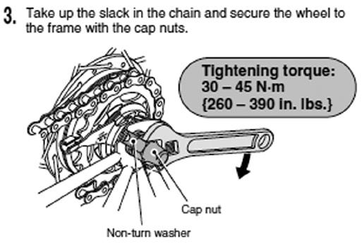


30 Technology General Safety Information Narrow-type chain 30
31 Checks and inspections Checks and inspections Please keep to the following inspection plan it ensures that the most important checks are done at the best possible times. It also ensures that you have no doubts about what you have to do and when. The setup and functionality of the bicycle could change during transport despite multiple checks being carried out during production and the final post-production check. Therefore, check the following before the first ride: Screws, bolts and pedals are all secure Stem, handlebars and seat post are all safely secured and adhere to the minimum insertion length Test the setup of the brakes and their effectiveness Check that the wheels and quick releases are secured Check that the suspension components are working properly Gears and lights Air pressure and tires Generally, a bicycle will change most in the first 100 kilometers; the spokes will bed in, the brake cables and gear cables settle into the housings and the bearings are broken in. Therefore, it is important that you have your first inspection carried out by your specialist retailer after kilometers or 4 6 weeks. This should encompass: Checking the wheels, which should be tensed and centered if required Oiling the chain and gear system Checking that screws, bolts and quick releases are secured Checking the torques (pedals, cranks, handlebars, seat) Checking the headset, brakes, gears and suspension parts, adjusting them where necessary All wear parts checked and replaced if required. In particular, this includes the brake friction partners (brake rubbers, brake pads, brake discs and rims). Other inspections and checks should be carried out: After every ride After rides in rainy or muddy conditions After around 300 to 500 kilometers After one year After 3000 kilometers Before and after every ride Check that: The lights and bell work and are safely secured The brakes are working safely and are secured The tires have not picked up any foreign objects or damage and that the rims are not damaged and are still running true (particularly after off-road rides) The suspension parts are working and are safely secured The gears are working properly and are safely secured The quick releases are tight The frame and fork have not been deformed or damaged If you are not certain that your bicycle is in perfect technical condition, you should have it checked by an expert! After rides in rainy or muddy conditions: Clean the chain, gears and brakes, and apply oil to the chain. After riding km or after 3 6 months: Clean your bicycle and oil the moving parts, excluding the brakes Repair any damaged paintwork Treat areas of rust or exposed metal areas Replace damaged or broken components Check the chain, front and rear chainrings, brake pads and rims for wear Check that all screws, bolts and quick releases are tight After 1 year: The measures undertaken in the first inspection should be repeated. That means: Cleaning the bicycle Oiling the chain and gear system Checking that screws, bolts and quick releases are secure Checking the torques (pedals, cranks, handlebars, seat) Checking the headset, brakes, gears and suspension parts, adjusting them where necessary After 3000 kilometers: A general inspection is once again due. That means that important parts of your bicycle should be checked over by your specialist retailer to see if they are working properly, secure, oiled or perhaps need replacing. That includes checking hubs and pedals, wheels as well as the headset, gear cables and brake cables. As with all mechanical components, your bicycle is subjected to high stress and wear. Various materials and parts may react differently when subjected to wear and high levels of stress. All of your bicycle components are designed to withstand a certain amount of strain and have a certain lifecycle. If this lifecycle is exceeded, it could result in accidents and serious injuries. You should therefore regularly check whether changes or cracks appear on your bicycle. If this is the case, allow the specialist retailer to check the bicycle and replace any possibly damaged parts. Instructions for care and maintenance Screws and torque wrenches When working on your bicycle, please ensure in particular that all screws that are key to safety are secured with the correct torque. The required torque is printed on many components. This amount is stated in Newton meters (Nm) and should be adjusted using a torque wrench. The best sort of torque wrench for this is one that clicks when it reaches the prescribed torque. Otherwise screws can snap or break. This could result in accidents and serious falls. If you don t own a torque wrench then you should always leave this work up to a specialist retailer! A table listing the most important torques for bolted connections is provided in the Technical information chapter. Care and maintenance Care and maintenance is a very important topic because you will only be able to enjoy your bicycle for years to come if you give it the required care and attention. And this also has a major bearing on its functionality, safety and warranty. 31
32 Fixing a flat tire A note from the outset: Whenever this instruction manual mentions cleaning fluid or oiling, then this never applies to the brakes, brake pads, brake discs or the brake rims. This would strongly compromise the effectiveness of the brakes. Clean your bicycle Regularly With a sponge With warm water and a little cleaning fluid (household washing up liquid also works well) Do NOT clean your bicycle With hot oil With grease With acids With brake cleaner (this should only be used to remove grease from brake discs or brake drums) With solvent-based liquids During cleaning also check your bicycle for Cracks (replace) Deformations (replace) Scratches and dents (check up) Paint damage (correct) You should pay extra attention to caring for your bicycle in difficult conditions, as many parts of the bicycle are particularly subject to corrosion in winter or at the seaside. Clean all parts made of stainless steel, zinc and chrome plated parts regularly, and help preserve them with spray wax. If you store your bicycle, clean it thoroughly first and then store it in a room with an even temperature with the tires pumped up to the prescribed air pressure. Please consider the environment and NEVER dispose of any remaining lubricants or cleaning products in your domestic refuse, drains or in a natural environment. Every town has a disposal unit where you can dispose of this sort of waste in a safe and environmentally friendly way. Your specialist retailer can also advise you on this. Fixing a flat tire Getting a flat tire during a ride is always an unpleasant experience, but it is not a problem that cannot be solved. You only require the following to continue your ride: Repair kit sandpaper, rubber solution and patch (or) replacement inner tube with replacement valve Two plastic tire levers if possible A pump An opened ended wrench for wheels with hub axle nuts (without quick release) In the case of side-pull rim brakes, you should open the release lever. Depending on the manufacturer, this is located either at the end of the brake arm or as a button (that you have to push) on the brake lever itself. In the case of hub and drum brakes, there is usually a way of extracting the cable from the brake. To remove a wheel with drailleur gears, you should first switch the chain to the smallest chainring; this way the gears provide the least resistance to removing the wheel. Then you should open the quick release in line with the instructions in the Technology chapter or loosen the allen cap nuts with a 15 mm wrench in an anticlockwise direction. Subsequently, you will be able to remove the wheel without any resistance from the chain. If you are not able to remove the wheel, your bicycle then has a fail-safe mechanism (either molded retainers or safety washers, which grip a slot in the dropouts). In this case, you have to turn the quick release or hub axle nut further. Now lift the bicycle up slightly and lightly strike the wheel from above; it should now fall downwards. To replace or patch the inner tube, you first have to remove it from the tire. To do this, place the wheel with the valve facing upwards and then remove the valve cap and the fastening nut: now let the air out of the tires. Place the first tire lever on the lower edge of the tire, opposite the valve, and lever the edge of the tire over the rim. Repeat this with the second lever every 10 cm along the wheel. This will then allow you access to remove the inner tube and valve from the tire. Locating a hole or tear in the tube requires you to pump it up. Now you should be able to hear where the air is escaping from the tube, or you could hold the tube underwater and look for the spot where the air bubbles are escaping. Let the tube dry, mark the hole and then roughen up the area around it with sandpaper. Apply the rubber solution and let it dry. Then press on the patch from edge to edge onto the applied rubber solution. The patch should then be left to dry on the air-filled inner tube for a few minutes. While you are waiting for it to dry, you should check the inside of the tube with your fingertips for foreign objects, small stones and dirt, removing these if detected. The rim tape should also be undamaged with all nipples covered. When refitting the repaired tube into the tires, start with the valve and then push the first half of the tube into the rim. Then you should pump the tube up slightly. As soon as it has regained its round shape, push the tube into the rim completely and push the tire back over the edge of the rim. When the tube has completely slipped back into the rim, check that it is properly positioned and adjust it if it is twisted. You are only now allowed to pump the tube up to the recommended tire pressure. The indicator on the side of the rim allows you to carry out a final check that everything is in the correct position. When refitting the wheel, ensure that you fit the front wheel the right way around: The quick release should be on the opposite side to the chain. Please place the wheel exactly in the center of the dropouts until it is tight. When refitting the rear wheel, you should first place the chain without tension over the smallest chainring. When you have tightened the hub axle nut or the quick release, you can reattach the brake cable. Please ensure that the brake pads are perfectly in line with the brake surfaces and then do a brake test. Congratulations! You have repaired a flat tire! In all of the following steps, the bicycle is standing on its wheels, not upside down on its seat and handlebars. To repair a flat tire, you have to remove the wheel in question, and to do that you have to open the corresponding brake. This requires different procedures depending on the type of brake. To find out the right approach, you must consult the brake manufacturer s instructions, as damage to the brakes can lead to accidents. In the case of cantilever and V brakes, place your hand around the wheel, push the brake pads against the rim and take out the brake cable on one of the brake arms. 32
33 Carbon components Carbon components If you have a carbon frame or carbon components on your bicycle, you have purchased a product that is particularly stable and light. These components are usually identifiable by their clear black surface fibers, which are constructed and interwoven in different patterns. As is the case with all particularly light parts, there are different aspects to consider than with metal components when constructing, servicing, cleaning, using and transporting your bicycle. Carbon is a strong material for making very stable components.!!! In contrast to metal components, you are NOT able to see if fibers are damaged, such as after a fall! After excess stress, like following a fall, carbon parts can suddenly break without any warning. This can cause very serious accidents. Therefore, it is vital to regularly check carbon parts. Listen for any cracking or other sounds during riding Look for deep scratches, holes or splinters Check if the stiffness of parts has changed Look for any areas where paint or fibers are coming off or where cracks and flaws in the surface are visible. If any of the above apply, then it is possible that your bicycle is damaged. You should not ride the bicycle until it has been inspected by a specialist! As a basic rule, no lubricants may be used during assembly. There are special synthetic assembly pastes for assembling carbon parts. These ensure that parts are solid and safely secured against twisting. Fastening screws also do not have to be so tightly fastened, as this could also damage parts which are sensitive to pressure. For instance, the frame may not be clamped in a work stand by a single tube. Affix a seat post securely in the frame and then attach this in a workstand. You should also not cut new threads in carbon parts, while the seat tube may also not be reamed inside. Carbon frames are not suitable for installing children s seats! When using or assembling carbon parts, please pay particular attention to the torques printed on components. You will find additional information on torques in the Technical information chapter. Please be particularly careful when checking your bicycle. Broken carbon parts have very small fibers and splinters that can cause very painful and dangerous injuries! In principle, carbon frames and components are glued synthetic parts. This glue is sensitive to high temperatures! Therefore you should avoid subjecting your carbon bicycle to high temperatures, like those that can occur in a car which has been parked in the sun. You should also refrain from painting or powder coating the carbon parts of your bicycle. Your specialist retailer will be happy to recommend some suitable products for caring for and cleaning your carbon parts. You shouldn t use any strong chemical cleaning products or products containing solvents as these could damage the surface of the parts! However, it is easy to clean everything with a soft cloth, warm water and some household washing up liquid. Car or spray wax is also well suited to preserving and caring for carbon parts. Parts subject to wear There are parts of your bicycle that are subject to wear, depending on their function. You are however able to keep this wear to a minimum by increasing the regularity and care with which you clean and service your bicycle. Typical parts subject to wear: The chain Rubber grips and bar tape The tires The chainwheels The brake pads The surfaces of disc and drum brakes Brake and gear cables The chainrings The seat Hydraulic oils and lubricants The bulbs of the light system The paint On top of that, the rims of your bicycle are also subject to wear if you have rim brakes. Regularly check the rims of your bicycle to see whether the wear markings are still visible or additional marks have appeared. Even if you can also see small cracks or small deformations to the rims, you should still have your bicycle checked by a specialist. Even if you can only see fine cracks or the rims are misshapen, please refrain from riding. After using two sets of brake pads, you should have the wear on your bicycle rims checked. The pads of the disk brakes can be subject to high levels of wear, particularly following off-road riding and sporty use. Check the brake pads before every ride. The thickness of the brake pads may not be less than 0.5 mm. Technical information Permissible total weight: The total weight is derived from the weight of the rider, the bicycle itself and any possible luggage: Weight of rider + weight of bicycle + weight of luggage = Total weight. The following weights are permissible: 110 kg for racing bicycles and mountain bicycles 120 kg for trekking, city and touring bicycles 130 kg for expedition bicycles Admissible load for racks In the event that nothing to the contrary is stated on the part, then 25 kg is the highest admissible load for a rear rack, with 10 kg being the highest admissible load for the front rack. Please check if your manufacturer advises differently! Torques for bolts and components Please always adhere to the prescribed torque! Otherwise parts could be damaged and broken! Screw fittings may only be tightened with the suitable matching torque wrench. If the torque is too 33
34 Warranty high or low, there is a danger of falling and sustaining serious injuries! Unless otherwise stated on the parts, the following torques apply: Component Torque NM Crank bolt square Crank bolt octalink Inside bearing shell Pedals 35 Nm Clamping screws A-Head stem 8 Nm Brake fastener racing brakes 5-9 Nm Brake fastener V brakes 8-10 Nm Cable fixing bolt brakes 6-8 Nm Brake pad fastener racing brakes 4-6 Nm Rear derailleur fastening bolt 8-10 Nm Cable fixing bolt gears 4-6 Nm Front derailleur bolt 5-7 Nm Cable fixing bolt front derailleur 5-7 Nm Seat post clamping screw M6 9,5 Nm Seat clamp screw M6 9,5 Nm Disc brake caliper on frame 7 Nm Brake disc on hub 4 Nm Clamping lever of the hub quick release 9-12 Nm Lockring of the derailleur cassettes Nm Bottle holder 5 Nm The following torques apply to carbon components unless otherwise stated on the parts: Component Bottle holder Front derailleur clamped fixture Brake lever fastening screw Stem clamp Stem-fork shaft clamp Shifter fastening screw Torque in NM 3 Nm 3 Nm 3 Nm 5 Nm 4 Nm 3 Nm When assembling carbon components you have to use the appropriate assembly paste! Using lubricants is not permitted in this case! Air pressure in the tires The air pressure in the tires is just as important for the riding resistance as for a safe ride. Please ensure that your tires always have the correct pressure, otherwise the tires could come off the rims, causing you to fall or injure yourself! Tyre width Recommended tyre pressure 20 mm 9.0 bar 130 psi 23 mm 8.0 bar 115 psi 25 mm 7.0 bar 100 psi 28 mm 6.0 bar 85 psi 30 mm 5.5 bar 80 psi 32 mm 5.0 bar 70 psi 35 mm 4.5 bar 65 psi 37 mm 4.5 bar 65 psi 40 mm 4.0 bar 55 psi 42 mm 4.0 bar 55 psi 44 mm 3.5 bar 50 psi 47 mm 3.5 bar 50 psi 50 mm 3.0 bar 45 psi 54 mm 2.5 bar 35 psi 57 mm 2.2 bar 32 psi 60 mm 2.0 bar 30 psi Warranty If you have any questions concerning your warranty, you should contact the bicycle retailer where you purchased your bicycle. The legal warranty of 2 years starts with the day you received your bicycle, which is stated in your receipt (keep this safe!). The best way of explaining the role of the warranty and guarantee is by using the example of parts subject to wear. There is usually no warranty on parts subject to wear, unless a problem with this part has been caused by a defect in the material or production. Parts subject to wear are listed in the Parts subject to wear chapter. The warranty therefore applies if: There has been a defect in manufacturing, production, material or information This defect has existed since you received your bicycle The warranty does not apply if: The bicycle was not delivered defective Damage has been caused by improper use, use in competition, violent use, as a result of an accident or other third party influences If cleaning, servicing and repairs were not conducted properly, incorrectly or by a non-expert You have made subsequent changes and additions to the bicycle which were not part of the bicycle when you received it. This also applies for damage which was caused when making these changes or additions with faulty workmanship. We would like to wish you happy riding with your new DHM bicycle! 34


35 Interesting cycling links Interesting cycling links These links provide important information on your bicycle and its components. Manufacturers websites usually contain both important tips for how to use and set up your bicycle and its parts as well as many of the respective instruction manuals top.html There is also a lot of basic information on bicycles and bicycle technology available at smolik-velotech.de. Although this information may not be at the cutting edge of modern developments, it is still very comprehensive. If you would like to learn more about bicycles, then more information and tips are also available in these magazines: Battery lockable 2 Seat post clamp 3 Bike lock 4 Dynamo 5 Controls and instruments 6 Vehicle identification number 7 V-Brake 8 Electric motor 9 Pedals and back pedaling brake What to consider when riding a pedelec! All general bicycl-related topics are described in the previous pages of this instruction manual. The regulations, rules and technical aspects specific to riding a pedelec are described in the following section. For more information on operating your pedelec and technical details, please read the enclosed instructions from the manufacturer of the motor, Before you set foot on the pedal always apply the pedelec s brakes! The motor drives as soon as you push the pedal. This force is unfamiliar and can lead to falls, hazards or accidents in traffic, which could result in injury. Practice operating and riding your pedelec in a quiet and safe place before you take it to public roads! Legal regulations! Please inform yourself about the applicable national regulations in your specific country! Germany Pedelecs fall under the jurisdiction of the same EU laws as a conventional bicycle. You can find the applicable national regulations on page 4. Pedelecs are subject to the same laws as conventional bicycles when using cycle tracks. Support from the motor may only be provided when the rider is pedalling No obligation to hold either insurance or driving licence. Making helmets compulsory is currently being discussed, please inform yourself about the applicable regulations before using your bike. However, we strongly recommend wearing a suitable bicycle helmet. 35
36 What to consider when riding a pedelec! Please note that the parts of a pedelec are subject to higher levels of wear than a bicycle without an additional integrated motor. This is due to the heavier weight of the pedelec and higher average speed from the motor. This increased wear is not a material defect and is not covered by the warranty. Typically this definition of wear includes the following parts Tyres Brake pads Chain Spokes The battery is subject to aging and is therefore also a wearable part. Please note that the battery gradually loses its capacity depending on its age and operating life. Take this into account when planning journeys and ensure that you switch to a new battery in good time. Replacement batteries can be purchased from your specialist retailer. The additional force from the motor could mean that you travel at a considerable higher speed than you are used to on your bicycle. Please take this into account when familiarising yourself with the pedelec! 36
37

38 HM Bike Consulting GmbH ch. des Prés 21 CH Chavannes de Bogis
Parts List. 7. Handlebars 8. Grips 9. Handlebar Stem 10. Front Brake 11. Front Wheel 12. Crank 13. Chain
 Woodworm Cruise Parts List 1. Free Wheel with Rear Hub 2. Fenders 3. Fender Stay 4. Quick Release 5. Saddle 6. Seat Post 7. Handlebars 8. Grips 9. Handlebar Stem 10. Front Brake 11. Front Wheel 12. Crank
Folding Dual Suspension MTB. Instruction Manual
 Folding Dual Suspension MTB Instruction Manual Introduction The Stowabike Folding MTB has been made to last and with proper maintenance, it will give you years of enjoyable rides and journeys. The following
BICYCLE ASSEMBLY INSTRUCTIONS. dutchcycles.com.au. Distribution Centre
 BICYCLE ASSEMBLY INSTRUCTIONS dutchcycles.com.au Distribution Centre Shed 68, 400-422 Somerville Road, Tottenham, VIC 3012 email: service@dutchcycles.com.au BICYCLE COMPONENTS KEY INTRODUCTION CONGRATULATIONS
comfort without compromising on performance and to fit your various needs on touring,
 Congratulations on your purchase of Goal-26X. Goal-26X is made to enhance comfort without compromising on performance and to fit your various needs on touring, shopping and communicating. Let s have fun
Santa Fe Cycles Assembly Guide Introduction
 Santa Fe Cycles Assembly Guide Introduction Congratulations on your purchase of your new Santa Fe bicycle. You have purchased a bicycle that has many features and qualities. Please take a few minutes and
model - CYPRESS DX W
 Contents model - CYPRESS DX W Maintenenace manual Read and Save these instructions Welcome Contents 1 Preparing Nothing makes us happier than seeing people out riding bikes. For over thirty years Giant
Ladies Shopper Bike Assembly Manual 28C03
 Ladies Shopper Bike Assembly Manual 28C03 Ecosmo Ltd 1 Know your bike 1. Wheel 2. Rear Derailleur 3. Chain 4. Crank Set 5. Pedal 6. Seat Quick Lock 7. Saddle and Post 8. Frame 9. Front Light 10. Front
Have questions? Chat with us live at raleighusa.com or call us at , 8am 5pm PST
 1 2 Have questions? Chat with us live at raleighusa.com or call us at 1-800-251-8435, 8am 5pm PST The bicycle you have purchased is a complex piece of equipment that must be properly assembled and maintained
Final Assembly Instructions Bikes with Quill Stems
 Final Assembly Instructions Bikes with Quill Stems Thank you for buying your new bicycle from L.L.Bean. Read these instructions carefully before beginning the final assembly. Prior to shipping, our expert
E-trike Li Assembly Guide
 PREPARATION 1. Read this assembly manual BEFORE commencing assembly. 2. Carefully remove all the components and packaged hardware from the shipping boxes. 3. Unpack the contents of the large double box
Final Assembly Instructions Bikes with Threaded Headsets
 Final Assembly Instructions Bikes with Threaded Headsets Thank you for buying your new bicycle from L.L.Bean. Read these instructions carefully before beginning the final assembly. Prior to shipping, our
Have questions? Chat with us live at raleighusa.com or call us at , 8am 5pm PST
 1 2 Have questions? Chat with us live at raleighusa.com or call us at 1-800-251-8435, 8am 5pm PST The bicycle you have purchased is a complex piece of equipment that must be properly assembled and maintained
Congratulations on your purchase of a JC Series Performer trike! The Performer JC Series is designed for everything from touring to commuting and
 Congratulations on your purchase of a JC Series Performer trike! The Performer JC Series is designed for everything from touring to commuting and shopping in the city. The JC Series frames are made of
3. Fit. 1 Owner s manual
 3. Fit NOTE: Correct fit is an essential element of bicycling safety, performance and comfort. Making the adjustments to your bicycle which result in correct fit for your body and riding conditions requires
Final Assembly Instructions Bikes with Threaded Headsets
 Final Assembly Instructions Bikes with Threaded Headsets Thank you for buying your new bicycle from L.L.Bean. Read these instructions carefully before beginning the final assembly. Prior to shipping, our
Thank you for purchasing a WIKE BOX BIKE!
 Thank you for purchasing a WIKE BOX BIKE! Contents Safety.....3 Front wheel.4 Kickstand..5 Handle Bar & Box 6 Seat post and Saddle 7 Final pre-ride check 8 Tools needed to assemble Bike: -High table or
Rothan Owner s manual
 Rothan Owner s manual www.islabikes.co.uk 1. Brake levers 2. Brake pads 3. Saddle 4. Seatpost 5. Seatpost clamp 6. Stem 7. Stem bolts 8. Headset 9. Headset spacers 10. Headset adjuster bolt 11. Handlebars
Have questions? Chat with us live at raleighusa.com or call us at , 8am 5pm PST
 1 2 Have questions? Chat with us live at raleighusa.com or call us at 1-800-251-8435, 8am 5pm PST The bicycle you have purchased is a complex piece of equipment that must be properly assembled and maintained
DM-RARD (English) Dealer's Manual. ROAD MTB Trekking. City Touring/ Comfort Bike. Rear Derailleur DURA-ACE RD-R9100 ULTEGRA RD-R8000
 Dealer's Manual. ROAD MTB Trekking. City Touring/ Comfort Bike. Rear Derailleur DURA-ACE RD-R9100 ULTEGRA RD-R8000") (English) DM-RARD001-03 Dealer's Manual ROAD MTB Trekking City Touring/ Comfort Bike URBAN SPORT E-BIKE Rear Derailleur DURA-ACE RD-R9100 ULTEGRA RD-R8000 CONTENTS IMPORTANT NOTICE... 3 TO ENSURE SAFETY...
(English) DM-RARD001-03 Dealer's Manual ROAD MTB Trekking City Touring/ Comfort Bike URBAN SPORT E-BIKE Rear Derailleur DURA-ACE RD-R9100 ULTEGRA RD-R8000 CONTENTS IMPORTANT NOTICE... 3 TO ENSURE SAFETY...
Quattrocycle BV. Quattrocycle. User Manual. Last update February Quattrocycle BV Bremkant EJ Middelbeers. User Manual Quattrocycle 1
 Quattrocycle User Manual Last update February 2010 Quattrocycle BV Bremkant 6 5091 EJ Middelbeers User Manual Quattrocycle 1 Table of Contents Page Chapter 1: Introduction 3 Chapter 2: Instructions for
Lectric Cycles Mid-Drive Electric Motor Installation
 Lectric Cycles Mid-Drive Electric Motor Installation This write-up describes the installation of a Lectric Cycles electric motor. The model is the e-rad Mid-Drive 750 Watt conversion kit, installed on
Bicycle Owner's Manual Easy Access Bike
 Bicycle Owner's Manual Easy Access Bike AGE: FROM 9 YEARS OLD AND UP IMPORTANT Check bike after assembly or any adjustments. Consult bicycle retailer with questions. Always wear a helmet. Children should
USER GUIDE TO POWER ASSISTED BIKES
 USER GUIDE TO POWER ASSISTED BIKES 1 PAGE CONTENTS Page. 3 Unpacking Page. 3-4 Easy steps to get started Page. 5 General Assembly Instructions Page. 6 Aligning H/Bars, Page. 7 Tightening pedals onto Crank
Mini Glider Manual. Your Glider comes partially assembled. The front wheel and the handlebars require assembly.
 Mini Glider Manual Congratulations on your purchase of the Mini Glider! Your glider is designed for years of nearly carefree use by your child. These instructions include how to set up your glider and
Assembly Tools. Assembly will take 1-2 hours
 Assembly Tools Included in your parts box: Pedals Quick release skewer Reflectors (if not already installed) Toolkit (4+5mm combo Allen wrench, 13+15mm combo open-end wrench) Helpful Tools: Scissors (for
HOME ASSEMBLY INSTRUCTIONS
 HOME ASSEMBLY INSTRUCTIONS This Papillionaire Bicycle now belongs to you. It will take you to work, wait patiently outside your local cafe, and carry your groceries home. This is the start of your long-term
Special instruction of installation for SAINT FH-M800/RD-M800 and FH-M805/RD-M805
 Technical Service Instructions SI-5VB0E t RD-M805 / RD-M800 Rear derailleur Special instruction of installation for SAINT FH-M800/RD-M800 and FH-M805/RD-M805 A hub axle is an essential component for the
Front derailleur. Dealer's Manual DURA-ACE FD-R9100 ULTEGRA FD-R FD ROAD MTB Trekking. City Touring/ Comfort Bike DM-RAFD001-03
 (English) DM-RAFD001-03 Dealer's Manual ROAD MTB Trekking City Touring/ Comfort Bike URBAN SPORT E-BIKE Front derailleur DURA-ACE FD-R9100 ULTEGRA FD-R8000 105 FD-5801 Procedures for cable tension adjustment
ASSEMBLY GUIDE AROUND THE BLOCK - 1, 3, 7, & 21 SPEED SIXTHREEZERO
 ASSEMBLY GUIDE AROUND THE BLOCK - 1, 3, 7, & 21 SPEED SIXTHREEZERO OUR COMMITMENT We want you to love your bike as much as we do. If you run into any issues, no matter how small, let us know and we ll
DM-MBRD (English) Dealer's Manual. ROAD MTB Trekking. City Touring/ Comfort Bike. Rear Derailleur SLX RD-M7000 DEORE RD-M6000
 Dealer's Manual. ROAD MTB Trekking. City Touring/ Comfort Bike. Rear Derailleur SLX RD-M7000 DEORE RD-M6000") (English) DM-MBRD001-04 Dealer's Manual ROAD MTB Trekking City Touring/ Comfort Bike URBAN SPORT E-BIKE Rear Derailleur SLX RD-M7000 DEORE RD-M6000 CONTENTS IMPORTANT NOTICE... 3 TO ENSURE SAFETY... 4
(English) DM-MBRD001-04 Dealer's Manual ROAD MTB Trekking City Touring/ Comfort Bike URBAN SPORT E-BIKE Rear Derailleur SLX RD-M7000 DEORE RD-M6000 CONTENTS IMPORTANT NOTICE... 3 TO ENSURE SAFETY... 4
CRUZBIKE Quest 2.0 Assembly
 CRUZBIKE Quest 2.0 Assembly CRUZBIKE Quest 2.0 Assembly... 1 General notes on assembly... 2 Un box and evaluate the frame and major parts... 2 Unfold the rear swing arm and arrange the frame... 3 Rear
KIDS SCOTT 2011 BIKE OWNERS MANUAL
 SCOTT 2011 BIKE OWNERS MANUAL B SCOTT SPORTS SA 17 RTE DU CROCHET 1762 GIVISIEZ SWITZERLAND 2009 SCOTT SPORTS SA, ALL RIGHTS RESERVED SCOTT-SPORTS.COM CONTENT Congratulations P. 004 General introduction
Assembly Tools. Assembly will take about an hour
 Assembly Guide Assembly Tools Included in your parts box: Pedals Toolkit (4+5mm combo Allen wrench, 13+15mm combo open-end wrench) Touch-up paint Spare fuses (for battery) Assembly will take about an hour
KIDS SCOTT 2013 BIKE OWNERS MANUAL
 SCOTT 2013 BIKE OWNERS MANUAL SCOTT SPORTS SA 17 RTE DU CROCHET 1762 GIVISIEZ SWITZERLAND 2011 SCOTT SPORTS SA, ALL RIGHTS RESERVED SCOTT-SPORTS.COM B content Congratulations... P. 004 General introduction...
EZee Glider Manual. Tools needed for Assembly: Wrench (included) Philips Screwdriver (not included) Assembly Instructions
 Philips Screwdriver (not included) Assembly Instructions") EZee Glider Manual Congratulations on your purchase of the EZee Glider! Your glider is designed for years of nearly carefree use by your child. These instructions include how to set up your glider and
EZee Glider Manual Congratulations on your purchase of the EZee Glider! Your glider is designed for years of nearly carefree use by your child. These instructions include how to set up your glider and
THE BRUCE-EN OWNER S MANUAL
 2018-08-THE BRUCE-EN OWNER S MANUAL 1 11 2 3 4 12 13 5 6 7 8 14 15 16 9 10 1 Frame 10 Pedal 2 Saddle 11 Handlebar with grips and brake lever 3 Seat post 12 Suspension fork 4 Saddle clamp 13 Tyre 5 Brake
TRAILMATE METEOR ASSEMBLY MANUAL
 TRAILMATE METEOR ASSEMBLY MANUAL (DISC BRAKE VERSION) The Trailmate Meteor recumbent has been designed for easy assembly. This means more time to enjoy the smooth ride with single speed, 3 speed coaster
ASSEMBLY GUIDE TRUE GRIT. LaufCycling.com
 ASSEMBLY GUIDE TRUE GRIT LaufCycling.com Congratulations on your True Grit! We understand you are in a hurry to go riding a.s.a.p. - but please take a deep breath and read this installation guide first.
HELMETS SAVE LIVES!!! ALWAYS WEAR A PROPERLY FITTED HELMET WHEN YOU RIDE YOUR SCOOTER. DO NOT RIDE AT NIGHT. AVOID RIDING IN WET CONDITIONS.
 HELMETS SAVE CORRECT FITTING - MAKE SURE YOUR HELMET COVERS YOUR FOREHEAD. LIVES!!! ALWAYS WEAR A PROPERLY FITTED HELMET WHEN YOU RIDE YOUR SCOOTER. DO NOT RIDE AT NIGHT. AVOID RIDING IN WET CONDITIONS.
Beinn 29 Owner s manual
 Owner s manual Setting up your 4 13 8 12 1 14 15 19 16 7 5 6 5 22 20 9 10 11 21 2 3 1. Brake levers 2. Brake calipers 3. Rotors 4. Saddle 5. Seatpost 6. Seatpost clamp 7. Saddle clamp 8. Stem 9. Stem bolts
POWER ASSISTED BICYCLES OWNERS MANUAL
 POWER ASSISTED BICYCLES OWNERS MANUAL WE HAVE INCLUDED A BICYCLE OWNER S MANUAL WHICH YOU SHOULD REFER TO FOR ALL GENERAL CYCLE MAINTENANCE. CONTENTS Page. 3 Unpacking. Page. 3-4 Easy steps to get started.
Troubleshooting Guide
 Troubleshooting Guide This troubleshooting guide outlines quick fixes to the most common technical questions about the ElliptiGO. If the problem persists or you feel uncomfortable performing these actions,
MTB-EN. white/weiß OWNER S MANUAL
 12.2016-MTB-EN white/weiß OWNER S MANUAL 1 2 3 4 11 12 13 5 6 7 14 15 16 17 18 19 20 8 9 10 1 Frame 11 Rear shock 2 Saddle 12 Stem 3 Seat post 13 Handlebar with grips, brake and shift levers 4 Seatpost
ROAD Wheel Set. Dealer's Manual WH-9000-C24-CL WH-9000-C24-TL WH-9000-C35-CL WH-9000-C35-TU WH-9000-C50-CL WH-9000-C50-TU WH-9000-C75-TU
 (English) DM-WH0002-00 Dealer's Manual ROAD Wheel Set WH-9000-C24-CL WH-9000-C24-TL WH-9000-C35-CL WH-9000-C35-TU WH-9000-C50-CL WH-9000-C50-TU WH-9000-C75-TU WH-RS21 WH-RS61 CONTENTS IMPORTANT NOTICE...
Item N o.: Item N am e:southern Star 40cm Girls Cherry Bike
 Item N o.:42174868 Item N am e:southern Star 40cm Girls Cherry Bike Tighten them so they do not move and are horizontal. Check the handlebar is in good condition and the ends of the handlebar are
BELT DRIVE INDOOR CYCLING BIKE SF-B1712 USER MANUAL
 BELT DRIVE INDOOR CYCLING BIKE SF-B1712 USER MANUAL IMPORTANT! Please retain owner s manual for maintenance and adjustment instructions. Your satisfaction is very important to us, PLEASE DO NOT RETURN
DM-MARD (English) Dealer's Manual. ROAD MTB Trekking. City Touring/ Comfort Bike REAR DERAILLEUR XTR RD-M9100 RD-M9120
 Dealer's Manual. ROAD MTB Trekking. City Touring/ Comfort Bike REAR DERAILLEUR XTR RD-M9100 RD-M9120") (English) DM-MARD001-00 Dealer's Manual ROAD MTB Trekking City Touring/ Comfort Bike URBAN SPORT E-BIKE REAR DERAILLEUR XTR RD-M9100 RD-M9120 CONTENTS CONTENTS...2 IMPORTANT NOTICE...3 TO ENSURE SAFETY...4
(English) DM-MARD001-00 Dealer's Manual ROAD MTB Trekking City Touring/ Comfort Bike URBAN SPORT E-BIKE REAR DERAILLEUR XTR RD-M9100 RD-M9120 CONTENTS CONTENTS...2 IMPORTANT NOTICE...3 TO ENSURE SAFETY...4
Item N o.: Item N am e:40cm Boys Rival Bike
 Item N o.:42272892 Item N am e:40cm Boys Rival Bike 9 bell 8 grip 30 crash pad 10 brake lever 26 wheel reflector 22 saddle 23 seat post 25 rear reflector 24 quick release 6 handle bar 7 stem 2 top tube
Item Name: 30CM GIRLS STAR THE UNICORN BIKE
 Item No.: 42333753 Item Name: 30CM GIRLS STAR THE UNICORN BIKE Contents 1. Parts identification 1 2. Safety precautions 2 3. Check list 6 4. Assembly 7 5. Adjustment 14 6. Repair and Service 15 7. Warranty
Final Assembly Instructions Bikes with 16 Wheel Size
 Final Assembly Instructions Bikes with 16 Wheel Size Thank you for buying your new bicycle from L.L.Bean. Read these instructions carefully before beginning the final assembly. Prior to shipping, our expert
DM-RD (English) Dealer s Manual. ROAD Rear Derailleur RD-9000 RD-6800 RD-5800 RD-4700
 Dealer s Manual. ROAD Rear Derailleur RD-9000 RD-6800 RD-5800 RD-4700") (English) DM-RD0003-09 ROAD Rear Derailleur Dealer s Manual RD-9000 RD-6800 RD-5800 RD-4700 CONTENTS IMPORTANT NOTICE...3 TO ENSURE SAFETY...4 LIST OF TOOLS TO BE USED...6 INSTALLATION...8 Chain length...
(English) DM-RD0003-09 ROAD Rear Derailleur Dealer s Manual RD-9000 RD-6800 RD-5800 RD-4700 CONTENTS IMPORTANT NOTICE...3 TO ENSURE SAFETY...4 LIST OF TOOLS TO BE USED...6 INSTALLATION...8 Chain length...
Owner's Manual Product Line
 Owner's Manual 2017 Product Line Table of contents 1. Safety Information 2. Quick release procedure I. Installation II. Adjustment and operation III. Inspection of proper installation 3. Registering your
Rothan Owner s manual.
 Owner s manual www.islabikes.com www.islabikes.com 1. Brake levers 2. Brake pads 3. Saddle 4. Seatpost 5. Seatpost clamp 6. Stem 7. Stem bolts 8. Headset 9. Headset spacers 10. Headset adjuster bolt 11.
Front derailleur. Dealer's Manual XTR FD-M9000 FD-M9020 FD-M9025 DEORE XT FD-M8000 FD-M8020 FD-M8025 DEORE FD-M612 FD-M617 FD-M618 SLX FD-M672 FD-M677
 (English) DM-FD0003-06 Dealer's Manual ROAD MTB Trekking City Touring/ Comfort Bike URBAN SPORT E-BIKE Front derailleur XTR FD-M9000 FD-M9020 FD-M9025 DEORE XT FD-M8000 FD-M8020 FD-M8025 DEORE FD-M612
Original instruction manual
 Original instruction manual City bike, TrekkingATB bike Mountain bike, Racing bike Youth bike ISO 4210:2014 Pedelec E-bike EN 15194 Translation of the Original instruction manual Frame 1 Top tube 2 Down
7130 Lancer Rear Drive Magnetic Commercial Indoor Cycling Bike
 7130 Lancer Rear Drive Magnetic Commercial Indoor Cycling Bike Owner s Manual Made in Taiwan INDEX IMPORTANT SAFETY INFORMATION... 1 EXPLODED DRAWING... 2 PARTS LIST... 3 ASSEMBLY INSTRUCTION... 4-9 USER
MAGNETIC INDOOR CYCLING BIKE
 MAGNETIC INDOOR CYCLING BIKE SF-B1805 USER MANUAL IMPORTANT! Please retain owner s manual for maintenance and adjustment instructions. Your satisfaction is very important to us, PLEASE DO NOT RETURN UNTIL
Shifting Lever. Dealer's Manual. RAPIDFIRE Plus SL-M2000 SL-M3010 SL-M4010. Thumb Shifter SL-TZ500. ROAD MTB Trekking. City Touring/ Comfort Bike
 (English) DM-MDSL001-01 Dealer's Manual ROAD MTB Trekking City Touring/ Comfort Bike URBAN SPORT E-BIKE Shifting Lever RAPIDFIRE Plus SL-M2000 SL-M3010 SL-M4010 Thumb Shifter SL-TZ500 CONTENTS IMPORTANT
DM-RBRD (English) Dealer's Manual. ROAD MTB Trekking. City Touring/ Comfort Bike. Rear Derailleur
 Dealer's Manual. ROAD MTB Trekking. City Touring/ Comfort Bike. Rear Derailleur") (English) DM-RBRD001-00 Dealer's Manual ROAD MTB Trekking City Touring/ Comfort Bike URBAN SPORT E-BIKE Rear Derailleur CLARIS RD-R2000 CONTENTS IMPORTANT NOTICE... 3 TO ENSURE SAFETY... 4 LIST OF TOOLS
(English) DM-RBRD001-00 Dealer's Manual ROAD MTB Trekking City Touring/ Comfort Bike URBAN SPORT E-BIKE Rear Derailleur CLARIS RD-R2000 CONTENTS IMPORTANT NOTICE... 3 TO ENSURE SAFETY... 4 LIST OF TOOLS
DM-RCWH (English) Dealer's Manual. ROAD MTB Trekking. City Touring/ Comfort Bike. Wheel Set. WH-RX31 SM-AX x12 SM-AX x12
 Dealer's Manual. ROAD MTB Trekking. City Touring/ Comfort Bike. Wheel Set. WH-RX31 SM-AX x12 SM-AX x12") (English) DM-RCWH001-00 Dealer's Manual ROAD MTB Trekking City Touring/ Comfort Bike URBAN SPORT E-BIKE Wheel Set WH-RX31 SM-AX720-100x12 SM-AX720-142x12 CONTENTS IMPORTANT NOTICE... 3 TO ENSURE SAFETY...
(English) DM-RCWH001-00 Dealer's Manual ROAD MTB Trekking City Touring/ Comfort Bike URBAN SPORT E-BIKE Wheel Set WH-RX31 SM-AX720-100x12 SM-AX720-142x12 CONTENTS IMPORTANT NOTICE... 3 TO ENSURE SAFETY...
DM-FD (English) Dealer's Manual. Front derailleur FD-M9000 FD-M9020 FD-M9025 FD-M8000 FD-M8020 FD-M8025 FD-M612 FD-M617 FD-M618 FD-M672
 Dealer's Manual. Front derailleur FD-M9000 FD-M9020 FD-M9025 FD-M8000 FD-M8020 FD-M8025 FD-M612 FD-M617 FD-M618 FD-M672") (English) DM-FD0003-04 Front derailleur Dealer's Manual FD-M9000 FD-M9020 FD-M9025 FD-M8000 FD-M8020 FD-M8025 FD-M612 FD-M617 FD-M618 FD-M672 FD-M677 CONTENTS IMPORTANT NOTICE... 3 TO ENSURE SAFETY...
(English) DM-FD0003-04 Front derailleur Dealer's Manual FD-M9000 FD-M9020 FD-M9025 FD-M8000 FD-M8020 FD-M8025 FD-M612 FD-M617 FD-M618 FD-M672 FD-M677 CONTENTS IMPORTANT NOTICE... 3 TO ENSURE SAFETY...
9-speed super narrow. chain such as. CN-7701 / CN-HG93 8- / 7- / 6-speed narrow. chain such as CN-HG50 / CN-IG51
 - Technical Service Instructions SI-5VH0B t RD-M600 Rear derailleur General Safety Information WARNING The ST-M600 DUAL CONTROL lever is used for both gear shifting and braking operations. Make sure that
ORIGINAL INSTRUCTION MANUAL TECHNIBIKE E-MTB
 ORIGINAL INSTRUCTION MANUAL TECHNIBIKE E-MTB Mountainbike DIN EN ISO 4210:2014 Pedelec/e-bike DIN EN ISO 15194:2017-12 ENGLISH Part# 731-00178 If you leave this page unfolded when you read this guide,
Bicycle Owner s Manual Children s Bicycles
 Bicycle Owner s Manual Children s Bicycles The following manual provides assembly and maintenance instructions, as well as a guide to safe usage of your new bicycle. WARNING - Read the complete Owner s
ASSEMBLY GUIDE: Izip & Ezip Electric Bicycles with Rack-Top Mounted Batteries ( RTMB Bicycles )
") ASSEMBLY GUIDE: Izip & Ezip Electric Bicycles with Rack-Top Mounted Batteries ( RTMB Bicycles ) Please Refer to your Owner s Manual for Detailed Setup Instructions Technical & Customer Service: 1-800-377-4532
ASSEMBLY GUIDE: Izip & Ezip Electric Bicycles with Rack-Top Mounted Batteries ( RTMB Bicycles ) Please Refer to your Owner s Manual for Detailed Setup Instructions Technical & Customer Service: 1-800-377-4532
MTB-EN OWNER S MANUAL
 2018-01-MTB-EN OWNER S MANUAL 1 2 3 4 11 12 13 5 6 7 14 15 16 17 18 19 20 8 9 10 1 Frame 11 Rear shock 2 Saddle 12 Stem 3 Seat post 13 Handlebar with grips, brake and shift levers 4 Saddle clamp 14 Suspension
Front derailleur. Dealer's Manual SORA FD-R3000 FD-R3030 CLARIS FD-R2000 FD-R2030. ROAD MTB Trekking. City Touring/ Comfort Bike DM-RBFD001-01
 (English) DM-RBFD001-01 Dealer's Manual ROAD MTB Trekking City Touring/ Comfort Bike URBAN SPORT E-BIKE Front derailleur SORA FD-R3000 FD-R3030 CLARIS FD-R2000 FD-R2030 CONTENTS IMPORTANT NOTICE... 3 TO
Beinn Owner s manual
 Beinn Owner s manual www.islabikes.co.uk Setting up your Islabike You can view our how to set up your Beinn video guides on our website: http://www.islabikes.co.uk/info-hub/islabike-setup-video-guides
SANTA CRUZ BICYCLES Cable Routing Procedure MY17
 SANTA CRUZ BICYCLES Cable Routing Procedure MY17 Copyright Santa Cruz Bicycles 2017 TABLE OF CONTENTS SAFETY INSTRUCTIONS... 3 CABLE ROUTING... 3 INTRODUCTION...3 TOOLS AND SUPPLIES...3 REAR DERAILLEUR
User manual. Velo-Plus². Van Raam BV Aaltenseweg CM Varsseveld The Netherlands 06.13
 Velo-Plus² Van Raam BV Aaltenseweg 56 7051 CM Varsseveld The Netherlands 06.13 Contents Contents... Contact details manufacturer... Conformity... Introduction... Delivery... Intended usage... Safety measures...
Front derailleur. Dealer's Manual FD-M9000 FD-M9020 FD-M9025 FD-M8000 FD-M8020 FD-M8025 FD-M612 FD-M617 FD-M618 FD-M672 FD-M677
 (English) DM-FD0003-05 Front derailleur Dealer's Manual FD-M9000 FD-M9020 FD-M9025 FD-M8000 FD-M8020 FD-M8025 FD-M612 FD-M617 FD-M618 FD-M672 FD-M677 CONTENTS IMPORTANT NOTICE... 4 TO ENSURE SAFETY...
DM-WH (English) Dealer's Manual. MTB Wheel Set. Non-Series WH-MT68 WH-MT66 WH-MT35 WH-MT15
 Dealer's Manual. MTB Wheel Set. Non-Series WH-MT68 WH-MT66 WH-MT35 WH-MT15") (English) DM-WH0005-02 Dealer's Manual MTB Wheel Set Non-Series WH-MT68 WH-MT66 WH-MT35 WH-MT15 CONTENTS IMPORTANT NOTICE... 3 TO ENSURE SAFETY... 4 INSTALLATION... 6 Tire size...6 List of tools to be
(English) DM-WH0005-02 Dealer's Manual MTB Wheel Set Non-Series WH-MT68 WH-MT66 WH-MT35 WH-MT15 CONTENTS IMPORTANT NOTICE... 3 TO ENSURE SAFETY... 4 INSTALLATION... 6 Tire size...6 List of tools to be
Installation instructions for the Yepp Maxi Easyfit
 Installation instructions for the Yepp Maxi Easyfit The Yepp Maxi Easyfit is suitable for: - fitting to an Easyfit luggage carrier* (fig 1A) or - fitting in combination with the Yepp Maxi Easyfit carrier
Helios Separable Tandem Manual
 Helios Separable Tandem Manual This manual accompanies the Helios owners manual Introduction The separable kit fitted to your Helios tandem allows for even greater flexibility in the way you can enjoy
DM-TRRD (English) Dealer's Manual. ROAD MTB Trekking. City Touring/ Comfort Bike. Rear Derailleur DEORE XT RD-T8000 DEORE RD-T6000
 Dealer's Manual. ROAD MTB Trekking. City Touring/ Comfort Bike. Rear Derailleur DEORE XT RD-T8000 DEORE RD-T6000") (English) DM-TRRD001-01 Dealer's Manual ROAD MTB Trekking City Touring/ Comfort Bike URBAN SPORT E-BIKE Rear Derailleur DEORE XT RD-T8000 DEORE RD-T6000 CONTENTS IMPORTANT NOTICE... 3 TO ENSURE SAFETY...
(English) DM-TRRD001-01 Dealer's Manual ROAD MTB Trekking City Touring/ Comfort Bike URBAN SPORT E-BIKE Rear Derailleur DEORE XT RD-T8000 DEORE RD-T6000 CONTENTS IMPORTANT NOTICE... 3 TO ENSURE SAFETY...
DM-MBST (English) Dealer's Manual. ROAD MTB Trekking. City Touring/ Comfort Bike. Shifting lever. EZ-FIRE Plus ST-EF500 ST-EF510
 Dealer's Manual. ROAD MTB Trekking. City Touring/ Comfort Bike. Shifting lever. EZ-FIRE Plus ST-EF500 ST-EF510") (English) DM-MBST001-00 Dealer's Manual ROAD MTB Trekking City Touring/ Comfort Bike URBAN SPORT E-BIKE Shifting lever EZ-FIRE Plus ST-EF500 ST-EF510 CONTENTS IMPORTANT NOTICE... 3 TO ENSURE SAFETY...
(English) DM-MBST001-00 Dealer's Manual ROAD MTB Trekking City Touring/ Comfort Bike URBAN SPORT E-BIKE Shifting lever EZ-FIRE Plus ST-EF500 ST-EF510 CONTENTS IMPORTANT NOTICE... 3 TO ENSURE SAFETY...
Cycling Instructor Ltd.
 Information for Parents & Guardians Holiday Cycling Courses The Council provides free cycle training courses for children in the holidays. There is no cost to you. To join in pupils must be able to cycle
SG-7R46 SG-7R45 BR-IM41-R CJ-7S40 WARNING CAUTION SERVICE INSTRUCTIONS. Inter-7 Hub. Inter-M Brake Cassette joint NOTE:
 t WARNING It is important to completely understand the operation of your bicycle's brake system. Improper use of your bicycle's brake system may result in a loss of control or an accident, which could
MANUAL LEKKER BIKES 2016
 MANUAL LEKKER BIKES 2016 CONTACT For your own safety, never do work on your bicycle unless you feel absolutely sure about it. If you are in doubt or if you have any questions please contact our helpdesk:
BackCountry ebikes 2019 MULE Assembly
 BackCountry ebikes 2019 MULE Assembly Required Tools: Cutting Pliers (to cut box poly strapping and heavy bike banding) Scissors (to remove bubble wrap) Allen wrenches (3mm, 4mm, 5mm, 6mm) Wrenches (10mm,
KMX Kompact Sports Trike
 KMX Kompact Sports Trike Assembly Instructions 1.0 Introduction Thank you for choosing KMX! When properly assembled and set up your KMX will provide many years of enjoyment. KMX Karts Ltd does its utmost
INDOOR CYCLING BIKE SF-B1110 USER MANUAL
 INDOOR CYCLING BIKE SF-B1110 USER MANUAL IMPORTANT! Read all instructions carefully before using this product. Retain owner s manual for future reference. For customer service, please contact: support@sunnyhealthfitness.com
Cantilever Brake. Dealer's Manual. ROAD MTB Trekking. City Touring/ Comfort Bike
 (English) DM-RCBR001-00 Dealer's Manual ROAD MTB Trekking City Touring/ Comfort Bike URBAN SPORT E-BIKE Cantilever Brake BR-CX70 BR-CX50 BL-4700 BL-4600 BL-R780 BL-R3000 ST-7900 ST-6700 ST-5700 ST-4600
User manual. Velo Plus². Van Raam BV Aaltenseweg CM Varsseveld The Netherlands. Version 14.10
 Velo Plus² Van Raam BV Aaltenseweg 56 7051 CM Varsseveld The Netherlands Version 14.10 Table of contents Table of contents... 2 Contact details manufacturer... 2 Conformity... 2 Introduction... 3 Delivery...
MODEL: COMMUTER / ROAD BIKE
 STEP BY STEP BUILD GUIDE MODEL: COMMUTER / ROAD BIKE TABLE OF CONTENTS TOOLS 1 LET S GET STARTED 2 INSTALLING THE QUILL STEM 3 INSTALLING THE FRONT FENDER 4 INSTALLING THE QUICK RELEASE 5 INSTALLING THE
FRAMESET ASSEMBLY GUIDE TRUE GRIT. LaufCycling.com
 FRAMESET ASSEMBLY GUIDE TRUE GRIT LaufCycling.com Congratulations on your True Grit Frameset! We understand you are in a hurry to go riding a.s.a.p. - but please take a deep breath and read this installation
Safety manual Beinn 20/24/26
 Safety manual Beinn 20/24/26 Thank you for buying an Islabike! Your bike has been thoroughly checked and adjusted prior to delivery but there are a few tasks to perform before the bike is ready to ride:
Item N o.: Item N am e:50cm GIRLS BELLA CRUISER BIKE
 Item N o.:42272847 Item N am e:50cm GIRLS BELLA CRUISER BIKE grip brake lever mudguard mudguard braket free wheel rear hub saddle seat post rear reflector seat clamp chain guard chain wheel crank stem
Owner s Manual for Multi Speed & Freewheel Bicycles This Owner's Manual contains assembly, operation, and maintenance instructions.
 Your Model Number is: (write your model number here) Owner s Manual for Multi Speed & Freewheel Bicycles This Owner's Manual contains assembly, operation, and maintenance instructions. WARNING: - Check
TABLE OF CONTENTS INTRODUCTION
 R3 DISC MANUAL TABLE OF CONTENTS Introduction... 1 Frame Features... 2 Fork Preparation... 3 Small Parts... 5 Frame Preparation... 6 Brake Housing Installation... 7 Mechanical Cable Routing... 9 Electric
CLASS CYCLE P8000 OWNER'S MANUAL JOHNSON HEALTH TECH. CO., LTD.
 CLASS CYCLE P8000 JOHNSON HEALTH TECH. CO., LTD. No.26, Ching Chuan Rd., Taya Hsiang, Taichung Hsien 428, Taiwan, R.O.C. TEL: +886-4-2566700 FAX: +886-4-2560087 E-mail: sales@johnsonfitness.com http://www.johnsonfitness.com
User manual. Fun-2-Go. Van Raam BV Aaltenseweg CM Varsseveld Netherlands 06.13
 Fun-2-Go Van Raam BV Aaltenseweg 56 7051 CM Varsseveld Netherlands 06.13 Contents Contents... Contact details manufacturer... Conformity... Introduction... Delivery... Intended usage... Safety measures...
Dealer's Manual ROAD MTB Trekking City Touring/ URBAN SPORT E-BIKE Comfort Bike Front derailleur ALIVIO Non-Series
 (English) DM-MDFD001-02 Dealer's Manual ROAD MTB Trekking City Touring/ Comfort Bike URBAN SPORT E-BIKE Front derailleur ALIVIO FD-M4000 FD-M4020 Non-Series FD-MT400 CONTENTS IMPORTANT NOTICE... 3 TO ENSURE
SCOTT KIDS BIKE OWNER S MANUAL
 www.scott-sports.com SCOTT KIDS All rights reserved 2014 SCOTT Sports SA SCOTT Sports SA 17 Route du Crochet 1762 Givisiez Switzerland BIKE OWNER S MANUAL 2015 Distribution: SSG (Europe) Distribution Center
SCOTT SCOTT-SPORTS.COM BIKE OWNERS MANUAL OWNERS MANUAL / BEDIENUNGSANLEITUNG / MANUEL D UTILISATION
 SCOTT-SPORTS.COM SCOTT SPORTS SA / 17 RTE DU CROCHET / 1762 GIVISIEZ / SWITZERLAND 2008 SCOTT SPORTS SA, ALL RIGHTS RESERVED B CONFORME AUX EXIGENCES DE SECURITE SCOTT 2008 NF R30-020 BIKE OWNERS MANUAL
Trike-Bike Assembly Manual
 Be sure to check our website for more instruction details, videos and photographs as well as a complete listing of each Nut and Bolt for the Trike Bike. www.trike-bike.com.au Go to the page marked ASSEMBLY
Warning: Please read this entire manual before riding your Simbi. Failure to do so could result in serious injury or even death.
 Warning: Please read this entire manual before riding your Simbi. Failure to do so could result in serious injury or even death. Contents 1. OVERVIEW... 3 A. Thank You... 3 B. General Warning... 3 C. Important
V TR-EN. white/weiß OWNER S MANUAL
 V2017.01-TR-EN white/weiß OWNER S MANUAL 1 15 16 2 3 4 5 6 7 8 17 18 19 20 9 10 11 12 13 14 21 22 23 24 1 Frame 15 Stem 2 Saddle 16 Handlebar 3 Seatpost 17 Light 4 Saddle clamp 18 Mudguard 5 Pannier rack
Cycling. Scout s Name: Unit: Counselor s Name: Counselor s Ph. hypothermia, heat reactions, frostbite, dehydration, insect stings, tick.
 Cycling Merit Badge Workbookk This workbook can help you but you still need to read the merit badge pamphlet (book). No one can add or subtract from the Boy Scout Requirements #33216. Each Scout must do
owner s manual 2012 yeti arc
 owner s manual 2012 yeti arc YETI CYCLES 600 Corporate Circle, Unit D Golden, CO 80401 888.576.9384 www.yeticycles.com Table of Contents Brand Overview 06 Frame Features 08 Geometery 10 Maintenance Schedule