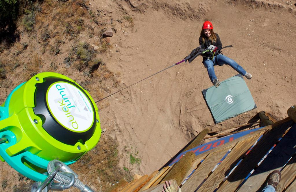
QUICKJUMP / QUICKJUMP XL FREE FALL DEVICE
|
|
|
- Whitney Maxwell
- 5 years ago
- Views:
Transcription
1 QUICKJUMP / QUICKJUMP XL FREE FALL DEVICE Operator Manual Models: QJ A / QJXL150-20A NOTE TO INSTALLERS Always Read Instructions Before Use Leave this Operator Manual attached to the QUICKjump Free Fall Device. The Operator Manual contains information relating to the proper use of the QUICKjump Free Fall Device and includes all product registration and warranty information. This document may only be removed by the end user. Ensure that this Operator Manual is readily available to operators at all times. Head Rush Technologies QUICKjump Free Fall Device Manual P/N Head Rush Technologies products are covered by a number of patents, including U.S. Patents 8,490,751; 8,851,235; 9,016,435; 8,851,235 and D654,412 & corresponding patents/applications in the USA and in other countries worldwide.

2
3 TABLE OF CONTENTS SAFETY INFORMATION 6 Symbols Used in this Manual 6 WARRANTY CONDITIONS 7 Customer Responsibility 7 CERTIFICATION 9 Standards 9 DESCRIPTION 10 SPECIFICATIONS 11 Location of Specification Labels 13 QUICKJUMP FREE FALL DEVICE PARTS 14 UNPACKING 15 Precautions 15 Unpacking the QUICKjump Free Fall Device 15 Storage 16 INSTALLATION 17 Precautions 17 Standards 17 Anchor Points 17 Harness 18 Secondary Connectors 18 Selecting a Location 18 Outdoor Installations 19 Mounting 19 Mounting Points 20 Single Point Mounting 20 Double Point Mounting 21 OPERATION 23 Operator Training 23 Operator/User Instruction 23 Harness 25 Carabiner Use 25 Mandatory Secondary Attachment 26 Operation 27 Webbing Retraction Procedure
4 Webbing Retraction Tips 28 INSPECTION & MAINTENANCE 29 Annual Recertification 29 Scheduled Maintenance and Inspections 30 Safety Precautions 30 Daily Inspection 31 Inspection Procedure 31 RipCord Inspection 32 Webbing Wear 33 Wear Tables 34 Troubleshooting Webbing Wear 37 Weekly Inspection 38 Sixth Month Inspection 38 Webbing Inspection 39 Nozzle Replacement 40 Webbing Line Replacement 42 Safety Precautions 42 Webbing Line Replacement Procedure 42 Replacement Parts 44 Troubleshooting 45 Transportation 45 MANUFACTURER S DETAILS 46 Address 46 Contact Details 46 4 headrushtech.com
5 IMPORTANT SAFETY NOTICE Recreational Descent Is A Dangerous Activity Read Before Installation & Operation Failure by the operator to heed any and all instructions, warnings and cautions for the correct installation, operation, care and maintenance of the QUICKjump Free Fall Device may result in serious injury and/or death. QUICKjump Free Fall Device Models QJ150-12A, QJXL150-20A and associated equipment are designed and specified for use as rapid descent devices. NOT SUITABLE FOR CLIMBING The QUICKjump Free Fall Device is not suitable for use as a belay device for climbing nor for use as personal protective equipment against a fall from height. Because of the large initial free fall and the rapid descent rate, this device is unsafe for any use other than the intended use stated above. Use of the QUICKjump Free Fall Device for any purposes other than those intended by the manufacturer are not permitted and may result in serious injury and/or death. Owners and operators of the QUICKjump Free Fall Device are responsible for the safety and supervision of any person using the QUICKjump Free Fall Device and are required to ensure that proper installation and operation procedures are followed at all times. Proper installation requires careful design and planning using QUICKjump and non-quickjump components. Owners and operators are required by the Manufacturer to read, understand, and follow all instructions in this Operator Manual regarding the correct installation and operation of the QUICKjump Free Fall Device prior to any use. Owners and operators are encouraged to seek the advice of their installer or a qualified engineering professional regarding the instructions in this Manual. These instructions must be made readily available to the operators and users at all times. Prior to installation and use of the device, all owners and operators must have read and shown to have understood all instructions, labels, markings, and safety information pertaining to the installation, operation, care, and maintenance of the QUICKjump Free Fall Device system, its component parts, and all associated hardware. Failure to do so can result in death, serious injury and equipment damage. Health and Safety Owners and operators must abide by all Standards, International, Federal, State and Provincial laws, and any specific health and safety regulations pertaining to the installation and use of this product. Site Rescue Plan Owners and operators must have devised an emergency rescue plan for any rider in distress at all sites operating QUICKjump Free Fall Devices. Operators must inform Users of the QUICKjump Free Fall Device of the procedure for rescuing a rider in distress prior to riding. headrushtech.com
6 SAFETY INFORMATION Symbols Used in this Manual The following safety symbols are used throughout this manual to highlight potential dangers. One or more precautions may be associated with practices and procedures described within this manual. Failure to adhere to any precautions highlighted can result in death, serious injury, and equipment damage. Ensure that the owner/operator reads and understands all safety procedures related to the working environment and the task they are undertaking. DANGER Indicates a hazardous situation exists that, if not avoided, will result in serious injury or death. WARNING Indicates a potentially hazardous situation that, if not avoided, could result in serious injury or death. CAUTION Indicates a potentially hazardous situation that, if not avoided, may result in injury or equipment damage. NOTE Indicates an action that must be taken to ensure personal safety and prevent damage to property or equipment. CARE FOR THE ENVIRONMENT Take care to minimize impact on the environment when carrying out this procedure. 6 headrushtech.com
7 WARRANTY CONDITIONS This QUICKjump Free Fall Device is warranted against factory defects in materials and workmanship (excluding Replacement Parts see below) for a period of two (2) years from date of purchase. This warranty applies only to the original purchaser, and is contingent upon the owner/operator maintaining and using the device in accordance with Manufacturer s instructions, including the requirement to continue to maintain annual re-certification as described in the Operator s Instruction Manual. This Warranty is in lieu of all other warranties, express or implied. The sole remedy for breach of this warranty, or for any claim in negligence or strict liability in tort, is the repair or replacement of any defective parts by Head Rush Technologies. Upon notice in writing, Head Rush Technologies will promptly repair or replace all defective items. Head Rush Technologies reserves the right to have any defective equipment returned to its plant, transportation pre-paid, for inspection before making a repair or replacement. This Warranty is null and void if parts other than genuine parts are used, or if any modifications or services have been performed on the device by anyone other than an authorized Head Rush Technologies servicing agent. This warranty does not cover any damages resulting from abuse to the device, damage in transit, or any other damage beyond the control of Head Rush Technologies. Head Rush Technologies makes no warranties in respect to trade accessories or component parts which are not made by Head Rush Technologies. Head Rush Technologies expressly excludes from this Warranty the replacement of Replacement Parts, which include the nozzle, the webbing line kit, carabiner and/or any other accessories supplied with the product. No person, agent or Distributor is authorized to give any warranty, other than the one herein expressed, on behalf of Head Rush Technologies, or to assume for it any liability pertaining to such products. Head Rush Technologies expressly disclaims any implied guarantee of merchantability, or claim as to whether the device is suited for a particular purpose. Purchaser agrees that Head Rush Technologies shall not be held liable to Purchaser/Operator for damages of any kind, including but not limited to, lost or projected profits, equipment down time, or any losses considered to be caused by non-operation or servicing/re-certification down time of the equipment. Customer Responsibility The following items are considered to be the responsibility of the Customer and are therefore not reimbursable under the terms of the warranty. Routine maintenance and inspection. Normal replacement of service items. Replacements required because of abuse, misuse or improper operational habits of the operator. headrushtech.com
8 Wearing parts such as nozzle, webbing line and carabiner. Normal deterioration due to use and exposure. A suitable secondary attachment must be installed on the webbing line by a qualified person. This warranty is subject to the following of the requirements of the Operator Manual supplied, Manufacturer s instructions, and the advice given by Head Rush Technologies service technicians. 8 headrushtech.com
9 CERTIFICATION Standards NOTE If the QUICKjump Free Fall Device is resold outside of the country of destination, the reseller must provide instructions for use, service, maintenance and repair in the language of the country of use. The QUICKjump Free Fall Device is used as a component within a freefall system and requires the design and use of other components within that system. It shall not be deemed suitable for use until it is ensured that the entire system complies with the requirements of appropriate regional, state, and federal directives/standards. QUICKjump Free Fall Device complies with the following prevailing Safety regulations: ASTM F : Standard Practice for Design of Amusement Rides and Devices headrushtech.com
10 DESCRIPTION The QUICKjump Free Fall Device is a descent device designed specifically for use as a component within a free fall system. Two models are available: QJ150-12A QUICKjump Free Fall Device QJXL150-20A QUICKjump XL Free Fall Device The design of the QUICKjump Free Fall Device permits simple installation and removal and incorporates an advanced self-regulating brake system and automatic webbing line retraction. The patented braking mechanism offers riders an initial free fall followed by a consistent descent with a minimal variation in descent rate of both children and adults. There are no wearing parts in the brake mechanism, ensuring reliability remains high while maintenance and operating costs are kept to a minimum. The RipCord accessory for QUICKjump extends the free fall feeling and is optional on QUICKjump and QUICKjump XL devices. The length of the RipCord necessarily changes the proper installation height, and RipCord webbings are NOT interchangeable between models. Refer to the full specifications based on your device model and RipCord length for proper installation details. To protect the longevity of the QUICKjump Free Fall Device, installation, care and use of the QUICKjump Free Fall Device must be carried out in accordance with the instructions in this manual. 10 headrushtech.com
11 SPECIFICATIONS QUICKjump MODEL DIMENSIONS NET WEIGHT QJ150-12A QUICKjump Free Fall Device 380 x 320 x 216 mm (15 x 12.6 x 8.5 in) kg (44 lbs) MATERIALS CASING Aluminum Alloy INTERNAL PARTS Zinc Plated Steel Stainless Steel NOZZLE Modified Acetal plastic NOZZLE INSERT 304 Stainless Steel WEBBING LINE 20.8 mm Nylon Spectra webbing MINIMUM DISTANCE NOZZLE TO PLATFORM MAXIMUM DISTANCE NOZZLE TO PLATFORM MIN. RIDER WEIGHT MAX. RIDER WEIGHT 1.8 m (6 ft) 2.1 m (7 ft) 20 kg (44 lbs) 130 kg (285 lbs) MIN. OPERATING TEMPERATURE -10 C (14 F) MAX. OPERATING TEMPERATURE 40 C (104 F) MIN. STORED TEMPERATURE -20 C (-4 F) MAX. STORED TEMPERATURE 60 C (140 F) NO RIPCORD MINIMUM MOUNTING HEIGHT* MAXIMUM MOUNTING HEIGHT* 8 m (26 ft) 12.5 m (41 ft) 0.8 M LOW MOUNT RIPCORD (BLUE) MINIMUM MOUNTING HEIGHT* MAXIMUM MOUNTING HEIGHT* 5.3 m (17.4 ft) 8 m (26 ft) 1.5 M RIPCORD (LIME) MINIMUM MOUNTING HEIGHT* MAXIMUM MOUNTING HEIGHT* 9.5 m (31 ft) 14 m (46 ft) * Mounting heights are from nozzle to landing zone and may vary with the addition of authorized QUICKjump accessories. headrushtech.com
12 QUICKjump XL MODEL DIMENSIONS NET WEIGHT QJXL150-20A QUICKjump XL Free Fall Device 380 x 320 x 216 mm (15 x 12.6 x 8.5 in) 20.8 kg (46 lbs) MATERIALS CASING Aluminum Alloy INTERNAL PARTS Zinc Plated Steel Stainless Steel NOZZLE Modified Acetal plastic NOZZLE INSERT 304 Stainless Steel WEBBING LINE 20.8 mm Nylon/Spectra/Technora webbing MINIMUM DISTANCE NOZZLE TO PLATFORM MAXIMUM DISTANCE NOZZLE TO PLATFORM MIN. RIDER WEIGHT MAX. RIDER WEIGHT 1.8 m (6 ft) 2.1 m (7 ft) 20 kg (44 lbs) 130 kg (285 lbs) MIN. OPERATING TEMPERATURE -10 C (14 F) MAX. OPERATING TEMPERATURE 40 C (104 F) MIN. STORED TEMPERATURE -20 C (-4 F) MAX. STORED TEMPERATURE 60 C (140 F) NO RIPCORD MINIMUM MOUNTING HEIGHT* 10 m (33 ft) MAXIMUM MOUNTING HEIGHT* 20 m (65.5 ft) 1.5 M RIPCORD (LIME) MINIMUM MOUNTING HEIGHT* 12.5 m (41 ft) MAXIMUM MOUNTING HEIGHT* 22 m (72.2 ft) * Mounting heights are from nozzle to landing zone and may vary with the addition of authorized QUICKjump accessories. 12 headrushtech.com
 headrushtech.")
13 Location of Specification Labels INFORMATION LABEL SERIAL NUMBER QJ150-12A SN QJXL150-20A SN SPECIFICATION LABEL CERTIFICATION LABEL COVER LABEL (Both Sides) headrushtech.com
14 QUICKJUMP FREE FALL DEVICE PARTS MOUNTING POINTS HANDLE CASING COVER (BACK) COVER (FRONT) WEBBING NOZZLE OVERLOAD PROTECTION ASSEMBLY SECONDARY ATTACHMENT POINT CARABINER RipCord webbings are NOT interchangeable between the QUICKjump and QUICKjump XL Devices. Furthermore, the RipCord webbings are NOT designed or intended for use in any other device. These webbings have been specifically engineered for safe use in only the QUICKjump line of devices. Both devices can utilize a 1.5 m RipCord but the webbings are different as indicated by the handle color and color of the main webbing line. Installation of the wrong webbing in the wrong device can result in improper operation and potentially hazardous or dangerous fall conditions. Riders MUST meet the operational and safety guidelines set forth in your Operators Manual. Please double check and verify the safety limits set forth in the Operator Manual before live operation. The RipCord webbing is a proprietary auxillary webbing for the QUICKjump family of devices only. These webbings are NOT COMPATIBLE with the zipstop Zip Line Brake, TRUBLUE Auto Belay or any other devices. The RipCord is not designed for other uses, and RipCord is the ONLY safe and approved way to extend the free fall distance of the QUICKjump device. Any RipCord that is exposed and no longer sealed should be taken out of service immediately. This should not be confused with the OPA section that includes a zipper for daily inspection of the OPA. 14 headrushtech.com
15 UNPACKING Precautions LEAVE THIS OPERATOR MANUAL ATTACHED TO THE QUICK- JUMP FREE FALL DEVICE UNTIL INSTALLATION IS COMPLETE. CAN ONLY BE REMOVED BY END OWNER/OPERATOR The Operator Manual contains information relating to the proper and correct use of the QUICKjump Free Fall Device and includes all product registration and warranty information. The Operator Manual document may only be removed by the end operator. Ensure this manual is readily available to QUICKjump Free Fall Device riders at all times. DO NOT DISPOSE OF PACKAGING The cardboard box and internal packaging are required for the return of the QUICKjump Free Fall Device for the annual rectification inspection. Please keep packaging in a safe place until required. Receipt of the QUICKjump Free Fall Device The QUICKjump Free Fall Device is packaged in a recycled cardboard box and contains: 1 x QUICKjump Free Fall Device (model will vary depending on the specifics of your order): QJ150-12A QUICKjump without a RipCord QJ150-12A QUICKjump with 0.8m Low Mount RipCord QJ150-12A QUICKjump with 1.5m RipCord QJXL150-20A QUICKjump XL QJXL150-20A QUICKjump with 1.5m RipCord 1 x Carabiner 1 x Operator Manual The Free Fall Device is shipped with the webbing line and carabiner attached and does not require any further assembly. Unpacking the QUICKjump Free Fall Device To unpack the QUICKjump Free Fall Device: 1. Upon receipt of QUICKjump Free Fall Device, inspect for signs of shipping damage or contamination. If QUICKjump Free Fall Device shows any signs of damage or mishandling contact your Head Rush Technologies distributor. 2. Check all labels affixed to QUICKjump Free Fall Device are present and legible. headrushtech.com
16 Do not use the QUICKjump Free Fall Device after date shown here 3. Check the Certification Label for the Next Recertification Required date. If the date shown has passed or the label is missing or illegible the QUICKjump Free Fall Device must not be put into service. 4. Register your QUICKjump Free Fall Device online at com/registration PRODUCT REGISTRATION MUST BE COMPLETED The Product Registration must be completed by registering online at headrushtech.com/registration. This is critical for receiving product notifications and up-to-date information for the safe use of the QUICKjump Free Fall Device. 5. Read the Operator Manual and familiarize yourself with all aspects of installation, operation, care and maintenance. Storage If the QUICKjump Free Fall Device is to be left unused for longer than two weeks, ensure the unit is clean and dry and webbing line is fully retracted into the unit. When returning the QUICKjump Free Fall Device to duty after an extended period of inactivity always carry out a full inspection and operational check. DO NOT STORE IN WET CONDITION After exposure to water or damp conditions thoroughly clean and dry the QUICKjump Free Fall Device. Ensure the QUICKjump Free Fall Device is not left with a wet webbing line retracted inside the casing. Always store in a clean and dry environment. 16 headrushtech.com
17 INSTALLATION Precautions ALWAYS USE DESIGNATED MOUNTING POINTS Never install the QUICKjump Free Fall Device using any part of the device apart from the designated mounting points. Incorrect mounting can result in serious injury or death. HARD IMPACTS MAY RESULT IN STRUCTURAL DAMAGE Dropping of, or hard impacts to, the QUICKjump Free Fall Device can result in serious damage to mounting points and internal parts and may compromise safety of operation. If the QUICKjump Free Fall Device is subjected to a hard impact, remove it from duty and return to the service agent for inspection. HEAVY ITEM - 20 KG Take care when lifting the QUICKjump Free Fall Device. Take care not to drop the device as this may result in serious injury or equipment damage. DO NOT MOUNT FULLY RIGID QUICKjump device should always be hung vertically, not rigidly mounted. A fully rigid mount will result in excessive/premature webbing wear. Standards Prior to installation, all Operators must be familiar with the requirements of all relevant Standards for anchor points, hardware and equipment used with the QUICKjump Free Fall Device. ANCHOR POINTS All anchor points and connectors used with the QUICKjump Free Fall Device must conform to any local, regional, federal and state requirements for such devices. Minimum requirements for anchor points must conform to the requirements of: EN Climbing wall anchor points. EN Anchor Devices. The location and anchor points for the QUICKjump Free Fall Device MUST comply with the following: Minimum load capacity of the anchor point(s): 10 kn (2248 lbs) in expected directions of application. Anchor points are not to be used by other devices or as attachments for hardware not associated with the QUICKjump Free Fall Device installation. headrushtech.com
18 Anchor points should be of a suitable size and type to correctly install any mounting hardware. HARNESS All harnesses used in conjunction with the QUICKjump Free Fall Device must comply with the following applicable standards: EN Personal protective equipment for prevention of falls from a height Full body harness EN Personal protective equipment for prevention of falls from a height Sit harness. EN Type A. Full Body Harness EN Type B. Small Full Body Harness EN Type C. Sit Harness Harnesses must be of the correct size and fitment and be in serviceable condition. SECONDARY CONNECTORS All secondary connectors and hardware used in the installation of the QUICKjump Free Fall Device must conform to the requirements of: EN Types of connectors for personal protection. EN Types of connectors for mountaineering. All connectors, hooks, D-rings and shackles used to mount the QUICKjump Free Fall Device must meet a minimum breaking load of 10kN (2248 lbs) and be of compatible size, shape and strength for the mounting point to which they are attached. SELECTING A LOCATION The QUICKjump Free Fall Device is to be mounted at the top of the descent route with the nozzle and webbing line pointed down. When selecting a location to mount the QUICKjump Free Fall Device always check: All anchor points have a minimum load capacity of 10kN (2248 lbs) and conform to all regional, local, federal and state requirement for such devices. The QUICKjump Free Fall Device will hang vertically over the line of descent with the nozzle pointing down. All paths that can be used by the rider when connected to the QUICKjump Free Fall Device are free of sharp edges and high friction surfaces that may damage the webbing line. 18 headrushtech.com
19 Ensure that the descent path and landing area are free of other riders, pedestrians or obstacles that may cause entanglement or restrict the rider s descent. Choose a location that has a non-trafficked landing area below, without obstructions that would interfere with free and clear descent of rider. Ensure that the rider s line of descent has full clearance from obstacles within its fully extended range and is free to swing in all directions when in use. Any areas that may come into contact with the rider must be padded or protected. Install the device at the top of a structure where it can be safely reached for inspections and servicing. Always mount this device vertically overhead, so that the webbing line extends and retracts in a way that minimizes dangerous pendulum swings. SAFE LANDING AREA A protective fall attenuation surface must be used and centered below the landing point of the device, extending as required to adequately protect participants from injuries. It is recommended the surface meet ASTM F1292 specification for Impact Attenuation of Surfacing Materials for a critical fall height of 3ft (1m). A larger surface may be required in windy conditions. OUTDOOR INSTALLATIONS The QUICKjump Free Fall Device may be installed outdoors. It is recommended that in wet or aggressive environments the QUICKjump Free Fall Device is protected from the direct ingress of water or foreign objects. NOTE Prolonged exposure to the elements will increase the risk of internal corrosion and degradation of the webbing line resulting in increased operation and servicing costs. Use caution when operating the device in wind at speeds greater than 15 m/s (34 mph). High wind speeds can affect the downward path of the rider. Mounting With a suitable location for the QUICKjump Free Fall Device selected the device must be mounted only using the methods and hardware described in this manual. When mounting the QUICKjump Free Fall Device be aware of the following precautions: headrushtech.com
20 Anchor points must be capable of withstanding a minimum load of 10kN (2248 lbs) in expected direction of load application. All connectors, hooks, D-rings and shackles used to mount the QUICKjump Free Fall Device must meet a minimum breaking load of 10kN (2248 lbs) and comply with all relevant standards. All secondary connectors must be of compatible size, shape and strength to the mounting point to which they are attached. The QUICKjump Free Fall Device is free to pivot in all directions and should not bind the mountings or be able to impact upon the surrounding structure. MOUNTING POINTS USE ONLY THE DESIGNATED MOUNTING POINTS Use only the correct mounting points designated for single or double point mounting. Use of incorrect points can result in equipment damage. Ensure all mounting hardware is secure but free to pivot in mounting point. The QUICKjump Free Fall Device is manufactured with a single central pivot mounting point, an offset mounting point and a formed handle located at the top of the casing. These mounting points are located on the central plate and are located to ensure the unit hangs centrally and vertically with the webbing line nozzle pointing down. MOUNTING HEIGHT When device is mounted, the distance between the nozzle height and platform height must be between 1.8 m (6 ft) and 2.1 m (7 ft). A minimum distance of 1 m (3 ft) must be maintained between the QUICKjump Free Fall Device and any adjacent structure. The Side Covers are a sacrificial protective cover designed to prevent damage to both the device and any adjacent surface. Should the covers become excessively worn, damaged, or aesthetically unpleasing, they should be replaced by the Operator. Details of replacement parts may be found in the Spare Parts & Accessories section of this manual. SINGLE POINT MOUNTING Single point mounting is the preferred method of mounting your QUICKjump Free Fall Device to maximize webbing life. For single point mounting, the QUICKjump Free Fall Device is installed using the central mounting point, as 20 headrushtech.com

21 shown, with a longer non-loaded secondary mount utilizing the offset mount or handle mounting points. For Single Point mounting use only the central mounting point as shown. Ensure mounting hardware is secure and the unit is free to pivot in all directions. DOUBLE POINT MOUNTING For Double Point mounting use only the Offset mounting point and Handle as shown. Ensure mounting hardware is secure but free to pivot around the mounting point. NOTE When Double Point mounting as shown, ensure that the attachments are equalized so that the load is shared equally between the anchor points and the QUICKjump Free Fall Device hangs vertically and is symmetrical about its center. BACK-UP MOUNT (UNLOADED) PRIMARY MOUNT Two evenly loaded mounts to separate anchor points Single Point Double Point headrushtech.com
 CENTER (PLUMB) LINE Any areas that may come into contact with the rider must be padded or protected Adequate protection must be in place for participants that")
22 MOUNTING HEIGHT RANGE QJ: 5.3 m (17.4 ft) min m (46 ft) max. QJ XL: 10 m (33 ft) min m (72.2 ft) 1m (3.2ft) CENTER (PLUMB) LINE Any areas that may come into contact with the rider must be padded or protected Adequate protection must be in place for participants that fall upon landing 22 headrushtech.com
23 OPERATION Owners and Operators of the QUICKjump Free Fall Device are responsible for the safety and supervision of any person using this equipment and are required by the manufacturer to read, understand and follow all instructions in this Operator Manual regarding the correct installation and operation of the QUICKjump Free Fall Device prior to any use. UNSAFE OPERATION Remove QUICKjump Free Fall Device from service immediately if there is any concern over its correct operation or user safety. Do not return QUICKjump Free Fall Device to service until it has been inspected and completed a recertification inspection and test by an approved Head Rush Technologies Service Agent Operator Training All personnel involved in the operation of the QUICKjump Free Fall Device must be trained and deemed competent in the following aspects of QUICKjump Free Fall Device operation: Transportation and storage. Installation, use of attachment points and attachment methods and hardware. Rider requirements and instruction. Personal safety while assisting riders during operations or during required inspections and/or servicing and maintenance of equipment. Inspection, cleaning, and scheduled servicing of the QUICKjump Free Fall Device, its component parts and associated attachment hardware. Operator must be present during operation. Operator/User Instruction NEVER DESCEND WITHOUT BEING CORRECTLY ATTACHED Ensure carabiners are attached to designated attachment points of the harness, the latch is fully closed and the gates engaged before use. Failure to do so can result in serious injury or death. headrushtech.com
24 RIDERS MUST MEET CRITERIA FOR USE The QUICKjump Free Fall Device should not be used by anyone that is/has: Weight over 130kg (285lbs) Weight under 20kg (44lbs) Pregnant Any type of heart condition or heart-related issues Any type of spinal injury or weak spine condition A weak physical constitution or poor physical conditioning If you have any physical or medical conditions that may affect your ability to ride consult a medical professional prior to participation. Prior to clipping in, all riders must be instructed in the proper and correct use of the QUICKjump Free Fall Device. Operators are to ensure all riders are familiar with the site rescue plan in the event the rider becomes distressed. Prior to riding, the user and operator must be aware of, completely understand, and obey the following precautions: Never exceed the weight range of the device. Only to be used by one person at a time. Ensure that operators are anchored to the platform at all times. Riders must be anchored to the platform AND attached to the QUICKjump UNTIL THEY ARE READY to descend. Visually inspect the webbing line, carabiners and the device to ensure that everything is in proper working order. Never continue operation if the webbing line fails to fully retract. DO NOT pull out any excess webbing line prior to descent. The webbing line must be fully retracted or under tension prior to operation. Check the harness is correctly fitted and tightened. Check that the carabiners from the QUICKjump Free Fall Device line are connected to the designated attachment point(s) on the harness and the gates are properly closed. PINCH HAZARD Keeps fingers clear of carabiners and harness attachment point when descending. Loading may cause pinch. Ensure the carabiner latch gates are fully closed and locked. If both the primary and secondary carabiners are attached to the same 24 headrushtech.com
25 harness attachment point, the carabiner latch gates should face opposite directions. If the primary and secondary carabiners are attached to different harness attachment points, the carabiner latch gates should be facing away from the rider. Never permit the webbing line to wrap around the legs, arms, neck, other body parts or loose clothing of the rider. Never descend from alongside or above the QUICKjump Free Fall Device. Prior to descent, ensure descent path and landing area are free of people and obstructions. When ready to descend, step straight down off platform. Always descend feet first and straight down using feet to fend off obstacles and prepare for landing. Upon landing, unclip the carabiners from the harness and allow the device to take up slack in the webbing and create tension before releasing the webbing line to be retracted freely and fully back into the QUICKjump Freefall Device. Harness USE AN APPROVED HARNESS Always use a harness complying with the standards specified in this manual. Ensure the harness is appropriate for use, in serviceable condition and correctly fitted. Always follow the harness manufacturer s instructions for fitment, care and use. Children under the age of 10 years must only use a full body harness. Use of a helmet is strongly recommended. Carabiner Use One EN 362 certified triple locking carabiner is installed on the primary attachment point of the webbing assembly. The carabiner must be checked and be in serviceable condition before any use. Ensure the carabiner is only loaded along the vertical direction (i.e. not cross loaded). The webbing assembly has a secondary attachment point to accommodate a mandatory secondary connector. headrushtech.com


 must be suitably rated")
26 Secondary Attachment Point Primary Attachment Point NOTE If the carabiner is damaged or unserviceable, only a double or triple locking carabiner may be used as a replacement carabiner MANDATORY SECONDARY ATTACHMENT POINT A secondary attachment point is provided on the webbing line above the primary carabiner loop. The secondary attachment point can be used as shown by attaching a sling or suitable connector through the secondary attachment point and attaching a second double or triple locking carabiner for participant attachment. The secondary carabiner must hang below the primary carabiner to ensure that the secondary attachment point is not loaded during normal operation. The following considerations should be made when adding the secondary attachment: Any sling or equivalent textile used (dog bone, rope, etc) must be suitably rated and meet the requirements of any applicable international, federal, state or provincial standards for its application. 26 headrushtech.com


27 Any connector utilized (carabiner, quicklink, etc) must be suitably rated and meet the requirements of any applicable international, federal, state or provincial standards for its application. Connections to the QUICKjump and QUICKjump XL webbing assembly have the potential for additional wear and must be included in daily webbing inspections. The secondary attachment point should not be loaded during standard operation due to the propensity for wear on the two bar tacks directly below the secondary attachment point when subjected to repeated loads. See below for an example secondary attachment that is not acceptable. OPERATION The primary carabiner is opened by rotating the gate s collar and pushing the gate open towards the center of the carabiner. Attach the primary carabiner to the correct attachment point on the harness with the latch facing away from the user. Allow the latch to snap shut, ensuring the collar has rotated back and is locked. Ensure that no clothing, webbing or other objects are obstructing the gate or latch. Double check that the gate on the carabiner is secure. Step 1 Slide Step 2 - Twist Step 3 Depress Step 4 Release Carabiner Operation headrushtech.com
28 Webbing Retraction Procedure RESETTING THE WEBBING STACK If the webbing does not retract entirely into the device, the webbing stack may need to be reset. TO RESET THE WEBBING STACK, fully extend the webbing and allow it to slowly retract while maintaining constant tension. This will ensure the stack lays flat inside the drum without any dead space. Do this any time poor retraction is suspected or incomplete retraction is noticed. Never manually feed webbing into the device. If webbing still does not fully retract after (3) attempts of resetting the webbing stack, remove QUICKjump from service and contact Head Rush Technologies or your Head Rush Tech Distributor WEBBING RETRACTION TIPS Proper webbing retraction is crucial, especially when using the QUICKjump near its maximum operating height. Fully extending the QUICKjump webbing, then allowing it to freely retract without line tension, may cause improper webbing stacking, incomplete retraction, and accelerated webbing wear. Always maintain tension on the line, especially after disconnecting a participant. This will ensure that webbing spools correctly inside the unit preventing voids or dead space from forming in the stack. Tension can be applied in three different ways: 1. An operator on the ground, after disconnecting a participant, can momentarily hold the line until the unit applies retraction tension. Then gently release the line to retract (using the weight of the RipCord/OPA assembly to maintain tension). 2. An operator adjacent to the device on the platform may gently hold the line to provide tension during retraction. 3. An operator on the ground may apply tension via a tag line attached to the end of the webbing for the first 3 m 4.5 m (10 15 ft) of retraction so that the webbing is able to stack firmly and correctly. ALWAYS FOLLOW CORRECT WEBBING RETRACTION PROCE- DURE Do not attempt to assist the retraction of the webbing for any reason. Doing so could lead to a dangerous binding of the webbing which can abruptly shorten the life of the webbing and cause significant drag in the system, accelerating webbing wear and roller contamination. A loose webbing stack from incorrect webbing retraction procedures can cause inconsistent and undesirable braking and proportionately large load changes to the rider. 28 headrushtech.com
29 INSPECTION AND MAINTENANCE Annual Recertification DO NOT OPERATE AFTER THE DATE SHOWN ON THE CERTIFI- CATION LABEL Operation of the QUICKjump Free Fall Device without a current Certification Label visible will render the unit not fit for use and void all warranty. The QUICKjump Free Fall Device requires an annual service and recertification inspection to be carried out by an authorized Head Rush Technologies service agent. The Certification expiration date is shown on the Certification Label located on the side of the front casing. Dismount the QUICKjump Free Fall Device and return to the Manufacturer at the address shown at the back of this Manual or to an Authorized Service Center prior to the expiration date. Do NOT use the QUICKjump Free Fall Device after date shown here. headrushtech.com
30 Scheduled Maintenance and Inspections The following inspection and service actions must be carried out by the operator or operator-trained staff. Inspection log forms can be found at headrushtech. com/service/inspection-logs. All personnel performing these actions must be trained in the correct procedures and deemed competent to do so. INSPECTION AND MAINTENANCE REQUIRED Failure to perform scheduled maintenance and inspections on the QUICKjump Free Fall Device may result in serious injury or death. Ensure that service/inspection staff are adequately belayed during inspections. Failure to do so can result in serious injury or death. NO UNAUTHORIZED SERVICING Do not attempt to carry out any maintenance, repair or service actions not detailed in the User Manual. Any unauthorized maintenance, repair or modifications to the QUICKjump Free Fall Device will compromise safety, render the unit not fit for use, and void the warranty provisions. NOTE Service in a clean environment. If QUICKjump Free Fall Device has been removed from its operational location for service, ensure that the service area is clean and free from contaminants. Ensure unit is securely placed on a sturdy work table and plastic side covers are not subject to damage. SAFETY PRECAUTIONS HEAVY OBJECT Ensure the QUICKjump Free Fall Device is secured during service to prevent accidental damage or injury from dropping. CAUTION SPRING LOADED PARTS The webbing assembly is spring loaded and will rapidly return into the device if released. This may result in damage or injury. 30 headrushtech.com
31 MAGNETIC PARTS The QUICKjump Free Fall Device contains strong magnets. Always ensure working environment is free of loose ferrous materials. Ingress of metal objects may compromise belay operation. Daily Inspection The QUICKjump Free Fall Device must be inspected daily for correct operation and overall condition. The daily inspection may be carried out with the unit in place or removed to a sturdy work table. INSPECTION PROCEDURE Ensure adequate lighting and unrestricted access are available to permit a thorough inspection of all areas of the QUICKjump Free Fall Device. This inspection should be completed either with the QUICKjump Free Fall Device dismounted or by climbing to the location of the QUICKjump Free Fall Device and anchoring in, so you may visually inspect the unit and the entire length of webbing. 1. Clean any dust, dirt or contamination off the casing and fittings with a clean cloth. DO NOT USE SOLVENTS OR ABRASIVES Clean with a cloth only. Do not use any cleaners, solvents or abrasives on any part of the QUICKjump Free Fall Device or its associated equipment. 2. Visually inspect the casing, mounting holes and plastic covers for wear, impact damage, cracking, deformation and corrosion. Replace any damaged items or remove QUICKjump Free Fall Device from service. 3. Check that all safety labels are in place and in good condition. 4. Check that date on Certification Label is current. 5. Inspect the condition of the carabiners, checking for: Wear and damage. Correct operation of the locking mechanism. If the carabiner gate does not automatically lock, clean and brush, lubricate with dry graphite or wax based lubricant only until fully operational. If full functionality cannot be restored, replace carabiner. 6. Inspect the entire exterior condition of the Overload Protection Assembly (OPA) checking that: Assembly is contained within the jacket. No excess threads are visible. headrushtech.com

32 OPA has not deployed. Ensure the black strip and stitching remains intact. Rupture of this component may indicate an overload event. ACTIVATION STRIP 7. Slowly pull out the entire length of webbing from the unit. As webbing is withdrawn inspect for: Damage, cuts or abrasion to stitching. Cutting, wear and abrasion to the surface or edge of webbing. Discoloration, fading or chalking of the surface. Heat and friction damage such as hard or shiny areas. Contamination from dirt or chemicals. Twisting or knotting. Replace webbing if any signs of wear or damage are present. 8. Allow the webbing to slowly retract into the casing while applying tension checking that the retraction action is strong and smooth. Ensure that the webbing line is fully retracted. 9. Inspect primary and secondary attachment points for cuts, damage or abrasion. Replace webbing if any signs of wear or damage are present. 10. Ensure that side covers are in place. 11. Complete and file the daily portion of the Daily & Weekly Device Inspection Log. 12. Return QUICKjump Free Fall Device to service. RIPCORD INSPECTION The RipCord should be inspected daily along with the device and webbing inspections. 1. Start where the RipCord meets the OPA, looking for excess wear, loose threads, or damage. 2. Move up the RipCord, inspecting the full outer webbing for defects, including tears, UV damage such as discolored, brittle or stiff webbing, cuts, visible abrasion damage, torn sewing joints or other defects. 3. Ask a partner to help, and pull the RipCord tight. Check that the outer webbing remains slack while the internal webbing is tight. If the outer webbing pulls tight, replace the RipCord immediately. 32 headrushtech.com
33 4. Finally, inspect where the RipCord meets the device webbing, and look for excess wear, loose threads, or damage. If any damage or defect is found, the webbing line must be replaced immediately. FAILURE TO MAKE DAILY INSPECTIONS AND/OR REPLACE THE COMPLETE WEBBING WHEN ANY SIGNS OF WEAR ARE PRESENT MAY RESULT IN SERIOUS INJURY OR DEATH OF A PARTICIPANT. Any indication of the webbing or unit being out of specification mandates the immediate removal of the webbing or device from service. WEBBING WEAR INSPECT WEBBING DAILY Webbing in your QUICKjump must be evaluated on a daily basis. A detailed description of when a webbing should be taken out of service is included in the Failure Table below. Webbing MUST be taken out of service by the time the webbing resembles the stage of wear designated in the Failure Table. Continued use of webbing with wear at or beyond the designated stage of wear below may result in serious injury or death. headrushtech.com


34 WEAR TABLES Webbing pictures outlined in red in the tables below show webbing that MUST be taken out of service and replaced immediately to continue using your QUICKjump. The green outlined photos show webbing that can be kept in operation. QUICKjump Degree of Wear Side Wear Face Wear NEW STAGE 1 STAGE 2 STAGE 3 STAGE 4 MOLDY WEBBING Any webbing showing signs of mold should be taken out of service. Table 1: QUICKjump Side & Face Wear 34 headrushtech.com


35 WEAR TABLES Webbing pictures outlined in red in the tables below show webbing that MUST be taken out of service and replaced immediately to continue using your QUICKjump. The green outlined photos show webbing that can be kept in operation. QUICKjump XL Degree of Wear Side Wear Face Wear NEW STAGE 1 STAGE 2 STAGE 3 STAGE 4 STAGE 5 MOLDY WEBBING Any webbing showing signs of mold should be taken out of service. Table 2: QUICKjump XL Side & Face Wear headrushtech.com


36 WEAR TABLES Webbing pictures outlined in red in the tables below show webbing that MUST be taken out of service and replaced immediately to continue using your QUICKjump. The green outlined photos show webbing that can be kept in operation. NEW Degree of Wear UV Damage STAGE 1 STAGE 2 Table 3: UV Damage 36 headrushtech.com
37 TROUBLESHOOTING WEBBING WEAR Symptoms Potential Causes Potential Solutions Participants are swinging excessively as they descend Encourage participants to step off the platform rather than jumping out. Participants should also jump vertically. Flailing motions (swinging arms and legs, leaning forward/ back, etc.) acts like pumping on a swing and can create more lateral movement. WEBBING FACE WEAR SIDE WEAR & LOOP FAILURE UV FADED WEBBING JACKET DAMAGE WEBBING IS MOLDY/ DISCOLORED Foreign objects, including dirt and/or dust have introduced damage to nozzle stainless steel surface QUICKjump is mounted incorrectly. Foreign objects, including dirt and/or dust have introduced damage to webbing assembly Webbing is rubbing on obstruction Normal use of QUICKjump Sun is damaging webbing Participants are pulling down on QUICKjump jacket as they jump Webbing is not being dried after being used in wet conditions Inspect nozzle for burrs and other damage. If damage is found, replace nozzle. Ensure that the QUICKjump is mounted according to Operator Manual, whether single or dual mounting. Make sure that the QUICKjump is not angles. Always mount QUICKjump vertically with nozzle pointed down. Cover the QUICKjump when not in use. Wipe the webbing with a dry cloth daily, after use. Move the obstruction so that it does not interfere with QUICKjump operation. Parts and webbing wear over time with normal operation, replace webbing as necessary. Remove QUICKjump at the end of day or cover unit and webbing after use. Coach participants to hold jacket up and away from face. Holding jacket down then jumping puts excess wear on jacket when webbing is tensioned and jerked upward. Whenever using the QUICKjump in wet conditions, take the unit down at the end of the day, extend the webbing in a sanitary environment, and allow webbing to dry outside of the unit. Do not store in wet condition. headrushtech.com
. Open the jacket and inspect the entire assembly checking that no threads are broken and that the webbing is in good condition.")
38 Weekly Inspection In addition to the daily inspection above, the following inspection procedures must be carried out on a weekly basis for the QUICKjump and QUICKjump XL. 1. Inspect the interior condition of the Overload Protection Assembly (OPA). Open the jacket and inspect the entire assembly checking that no threads are broken and that the webbing is in good condition. If any broken threads are found, the webbing line must be replaced immediately. See Daily Inspection for additional OPA inspection guidelines. 2. Complete and file the weekly portion of the Daily & Weekly Device Inspection Log. Six Month Inspection The QUICKjump Free Fall Device requires an in depth six (6) month inspection by the Operator to maintain its safe and efficient operation. For the six month inspections, the unit must be dismounted and removed to a sturdy work table. INSPECTION PROCEDURE 1. Dismount the QUICKjump Free Fall Device (refer to Installation Instructions) 2. Clean QUICKjump Free Fall Device using a clean cloth. 3. Carry out Steps 1 through 6 of the Daily Inspection. 4. Remove the nozzle Refer to Nozzle Replacement for removal procedure. 5. Inspect nozzle assembly for the following: Excessive wear to slot. Splitting, cracking and deformation Correct fitment in housing. Nozzle Wear Check nozzle for excessive wear around slot 38 headrushtech.com
39 WEBBING INSPECTION 1. With the nozzle assembly removed, pull out the complete webbing line, including approx. 100 mm (4 in) of the drum lead. See Nozzle Replacement for removal procedure. Place a line holding pin through the loop in the drum lead, above the joining link to prevent it retracting back into the unit. 2. Inspect both the upper (drum) webbing and the webbing line by passing the webbing slowly through your hands under a good light. Inspect the webbing for: Damage to stitching (cuts or abrasion). Cuts to webbing, especially to edges. Abrasion across the surface of the webbing, wear and fraying, especially to the edges and the webbing loops. UV degradation although difficult to detect, visual indications are discoloration, fading and chalking of the webbing surface. Chemical attack, this can result in soft or weak fibers, color change or flaking of the surface. Heat or friction damage, indicated by hard fibers or glazing of the surface. Contamination from dirt, grit, sand or rust. Twisting, knotting or permanent deformation of webbing Replace the webbing if any signs of damage or deterioration are present 3. Inspect the webbing joining shackle. Ensuring that: The shackle pin is secure and straight do not attempt to tighten. NOTE The shackle pin is secured with thread locking compound and any attempt to turn will compromise its security. The shackle is undamaged and in the correct orientation. The webbing around the link is not worn or damaged. Webbing Line Holding Pin headrushtech.com


40 4. Remove the line holding pin and allow the upper line to slowly retract into the casing. Inspect the webbing as it retracts and ensure that the webbing line does not twist. 5. Refit the nozzle assembly. 6. Complete and file the Biannual Device Inspection Log. 7. Return QUICKjump Free Fall Device to service. Nozzle Replacement If the nozzle assembly shows signs of excessive wear, damage or poor fit it must be replaced. USE ONLY GENUINE HEAD RUSH TECHNOLOGIES REPLACE- MENT PARTS ALWAYS REPLACE NOZZLE AS A PAIR If nozzle requires replacement always replace as a matched pair Do not mix worn and new nozzle pieces. To remove the nozzle assembly: 1. Place the QUICKjump Free Fall Device unit side cover down taking care not to damage the plastic side covers - Ensure device is secure and cannot fall. 2. Pull out the nozzle pin. 3. Hold on to the lower line to keep it from retracting and lift out the two half sections of the nozzle. 4. Fit a suitable pin in the loop of the webbing line to prevent it retracting back into the casing. Assembled nozzle Step 1 - Remove pin 40 headrushtech.com


41 Step 2 - Lift out top half To refit the nozzle assembly: NOTE: Webbing line not shown Step 3 - Remove lower half 1. Refit the lower half of the nozzle assembly into the recess on the casing. 2. Fit the upper half of the nozzle assembly. 3. Remove webbing pin and allow the webbing to slowly rewind into the casing until fully retracted. 4. Check QUICKjump Free Fall Device for correct operation. Step 1 Fit top half Step 2 Fit bottom half Step 3 Fit pin Assembled nozzle NOTE: Webbing line not shown headrushtech.com
42 Webbing Line Replacement If the lower webbing line shows signs of wear, damage or contamination then it will need to be replaced. Replace webbing line as follows: SAFETY PRECAUTIONS DO NOT ALLOW WEBBING LINE OR DRUM LEAD TO RETRACT INTO HOUSING With nozzle removed take care not to permit uncontrolled retraction of drum lead or webbing line into casing. Uncontrolled retraction will result in internal damage and require repair by the manufacturer. USE ONLY GENUINE HEAD RUSH TECHNOLOGIES REPLACE- MENT PARTS WEBBING LINE REPLACEMENT PROCEDURE To replace the webbing line: 1. Remove the QUICKjump Free Fall Device from service and place securely on the work bench. 2. Remove the Nozzle assembly Refer to Remove Nozzle Assembly. 3. While holding QUICKjump Free Fall Device securely, pull out the webbing line until the end of the drum lead and the joining shackle are exposed. 4. Locate the loop in the drum lead, approx. 100 mm (4 in) past the link - Place a suitable line holder pin through the loop in the drum lead to prevent it retracting back inside the casing. Drum Lead Webbing Line Line Holding Pin Webbing Joining Shackle Webbing joining link parts 42 headrushtech.com

43 5. Unscrew the shackle pin. 6. Remove webbing line and complete shackle assembly from the drum lead. 7. Fit new shackle supplied with the line Ensure the loop part of the shackle is fitted to the drum lead. THREAD LOCKING COMPOUND ON REPLACEMENT SHACKLE PIN Once the shackle pin is removed from the shackle assembly, it cannot be reused. Ensure the factory applied thread locking compound is present on the replacement shackle pin threads. 8. Fit the new webbing line, passing the threaded shackle pin through the loop as shown. Torque = 2 Nm Correct shackle fitment 9. Tighten the shackle pin to 2 Nm (18 lb-in), ensuring the threads are fully engaged and the end of the pin is flush with the joining shackle as shown. 10. Remove the line holding pin and allow the new webbing line to slowly retract until drum lead and joining link is inside casing. Ensuring that the webbing line does not twist. Once shackle pin is tightened, it must not be loosened or retightened. This will break the locking compound and the shackle pin may become loose. The shackle pin must be replaced if this happens. Ensure that the webbing line feeds squarely and without twists when retracting back into the QUICKjump Free Fall Device. Failure to do so may result in equipment failure, serious injury or death to participants. 11. Refit nozzle assembly Refer Refit Nozzle Assembly. 12. Slowly retract the webbing line into the casing, checking the action is smooth and adequate spring resistance is felt. headrushtech.com
44 13. Once webbing line is fully retracted, pull out webbing line a short distance using reasonable force and allow it to retract. Repeat two to three times to ensure webbing line is firmly wound onto the drum. 14. Return QUICKjump Free Fall Device to service and check for correct operation. Replacement Parts Your QUICKjump Free Fall Device is fitted with a number of user replaceable parts that may be refitted without the need to return the device to an authorized Head Rush Technologies service agent. Always follow the manufacturer s instructions as detailed in the User Manual and any Part Replacement Guide supplied when undertaking replacement of a part. NOTE For optimal performance of your QUICKjump Free Fall Device, only use genuine Head Rush Technologies spare parts and accessories. When ordering replacement parts, please specify the part number and description of the part. DESCRIPTION PART NUMBER Replacement Webbing Kit QUICKjump QUICKjump with 0.8m Low Mount RipCord QUICKjump with 1.5m RipCord QUICKjump XL QUICKjump XL with 1.5m RipCord Nozzle Replacement Kit QUICKjump QUICKjump XL Side Cover (with Label) QUICKjump QUICKjump XL To order replacement parts or accessories, contact your authorized Head Rush Technologies Distributor, Service Center, or go to 44 headrushtech.com
45 Troubleshooting Refer to the online troubleshooting section at for up-todate troubleshooting instructions or contact your authorized Head Rush Technologies Distributor or Service Center. Transportation To ensure the safe shipment of your QUICKjump Free Fall Device, it should only be shipped in authorized Head Rush Technologies packaging (box and packing material). If you have misplaced your original packaging, purchase replacement packaging from an authorized QUICKjump Free Fall Device Service Center, or online at You will be responsible for the cost of any damage and necessary repairs due to shipping your QUICKjump Free Fall Device in unauthorized packaging. CARE FOR THE ENVIRONMENT Reuse the original packaging when shipping Free Fall Device. headrushtech.com
46 MANUFACTURER S DETAILS Return the QUICKjump Free Fall Device to the Manufacturer at the address shown below for any recertification or unscheduled service or repairs. ADDRESS Head Rush Technologies th Street, Suite C Boulder, CO USA CONTACT DETAILS info@headrushtech.com
47
QUICKJUMP / QUICKJUMP XL FREE FALL DEVICE
 QUICKJUMP / QUICKJUMP XL FREE FALL DEVICE Operator Manual Models: QJ-150-12A / QJXL150-20A NOTE TO INSTALLERS Always Read Instructions Before Use Leave this Operator Manual attached to the QUICKjump Free
ARBOREAL CLIMBING SYSTEM
 ARBOREAL CLIMBING SYSTEM Operator Manual Model: ARB-33 NOTE TO INSTALLERS Always Read Instructions Before Use The Operator Manual contains information relating to the proper use of the Arboreal Climbing
INSTRUCTIONS FOR USE
 INSTRUCTIONS FOR USE 88004X Series D-Ring Extender 5000 lb Rated Connector Complies with ANSI Z359.1-1998, ANSI 10.14 and OSHA 1926 regulations and requirements. Reliance Industries P.O. Box 2046 Deer
WARNING! DO NOT THROW AWAY THESE INSTRUCTIONS! READ AND UNDERSTAND BEFORE USING EQUIPMENT!
 Guardian Fall Protection Kent, WA 800-466-6385 www.guardianfall.com GENERAL SYSTEM SELECTION CRITERIA: Selection of fall protection shall be made by a Competent Person. All fall protection equipment shall
User Instructions 1789 Parapet Wall Anchor
 User Instructions 1789 Parapet Wall Anchor This manual is intended to meet the Manufacturer Instructions as required by ANSI Z359.1 and should be used as part of an employee training program as required
INSTRUCTIONS FOR USE
 Rebar Chain Assembly INSTRUCTIONS FOR USE 7260XX Rebar Chain Assembly Complies with the current ANSI Z359.1-2007 and all applicable OSHA regulations and requirements. Reliance Industries P.O. Box 2046
WARNING! DO NOT THROW AWAY THESE INSTRUCTIONS! READ AND UNDERSTAND BEFORE USING EQUIPMENT!
 Guardian Fall Protection Kent, WA 800-466-6385 www.guardianfall.com GENERAL SYSTEM SELECTION CRITERIA: Selection of fall protection shall be made by a Competent Person. All fall protection equipment shall
OPERATION AND INSTRUCTION MANUAL Beam Trolley Model: BTA012N
 OPERATION AND INSTRUCTION MANUAL Beam Trolley Model: BTA012N WARNING: ALL PERSONS USING THIS EQUIPMENT MUST READ AND UNDERSTAND ALL INSTRUCTIONS. FAILURE TO DO SO MAY RESULT IN SERIOUS INJURY OR DEATH.
USER INSTRUCTIONS LARGE HOOK & STRAP ANCHORAGE CONNECTOR ! WARNING
 ROSE MODEL NUMBER USER INSTRUCTIONS LARGE HOOK & STRAP ANCHORAGE CONNECTOR! WARNING National standards and state, provincial and federal laws require the user to be trained before using this product. Use
INSTRUCTIONS FOR USE
 INSTRUCTIONS FOR USE 7100 Series Lanyards Complies with the current ANSI Z359.1-2007 and all applicable OSHA regulations and requirements. Reliance Industries P.O. Box 2046 Deer Park, TX 77536 Phone :
Retractable. Dual Leg. User Instructions. 3M Occupational Health and Environmental Safety. Fall Protection Equipment
 3M Occupational Health and Environmental Safety Fall Protection Equipment Dual Leg Retractable User Instructions User Instructions for the 3M TM Dual Leg Retractable Important: Keep these User Instructions
IMPORTANT: Record the product identification information from the ID label in the inspection and maintenance log in section 9.0 of this manual.
 Instructions for the following series products: Vacuum Anchor HLL System (See back page for specific model numbers.) User Instruction Manual Vacuum Anchor Horizontal Lifeline System This manual is intended
SUPER SLIDER BEAM ANCHOR ADJUSTABLE FROM Model # BWA030N
 SUPER SLIDER BEAM ANCHOR ADJUSTABLE FROM 12-30 Model # BWA030N IMPORTANT!!! ALL PERSONS USING THIS EQUIPMENT MUST READ AND UNDERSTAND ALL INSTRUCTIONS. FAILURE TO DO SO MAY RESULT IN SERIOUS INJURY OR
Rescue Ladder Basic Kit Model: LDR-BAS-CTS 18ft (5.48m)
") Rescue Ladder Basic Kit Model: LDR-BAS-CTS 18ft (5.48m) Patent # US 9,677,333 WARNING: ALL PERSONS USING THIS EQUIPMENT MUST READ AND UNDERSTAND ALL INSTRUCTIONS. FAILURE TO DO SO MAY RESULT IN SERIOUS
Rescue Ladder Basic Kit Model: LDR-BAS-CTS 18ft (5.48m) Patent # US 9,677,333 WARNING: ALL PERSONS USING THIS EQUIPMENT MUST READ AND UNDERSTAND ALL INSTRUCTIONS. FAILURE TO DO SO MAY RESULT IN SERIOUS
OPERATION AND INSTRUCTION MANUAL Flat Roof Anchor Model: FRA250L-10X-CTS
 OPERATION AND INSTRUCTION MANUAL Flat Roof Anchor Model: FRA250L-10X-CTS (Patent Pending) WARNING: ALL PERSONS USING THIS EQUIPMENT MUST READ AND UNDERSTAND ALL INSTRUCTIONS. FAILURE TO DO SO MAY RESULT
OPERATION AND INSTRUCTION MANUAL Swivel Anchor Model: HD26248
 OPERATION AND INSTRUCTION MANUAL Swivel Anchor Model: HD26248 IMPORTANT!!! ALL PERSONS USING THIS EQUIPMENT MUST READ AND UNDERSTAND ALL INSTRUCTIONS. FAILURE TO DO SO MAY RESULT IN SERIOUS INJURY OR DEATH.
OPERATION AND INSTRUCTION MANUAL ROLLER SLING Model: IN106.3FT & IN106.2FT
 OPERATION AND INSTRUCTION MANUAL ROLLER SLING Model: IN106.3FT & IN106.2FT IMPORTANT!!! ALL PERSONS USING THIS EQUIPMENT MUST READ AND UNDERSTAND ALL INSTRUCTIONS. FAILURE TO DO SO MAY RESULT IN SERIOUS
Instructions for The Rose Crossover Style Full Body Harness For Women
 P.O. Box 3026 Sherwood Park Alberta T8H 2T1 Phone: (780) 464-7139 Fax: (780) 464-7652 e-mail: inquiries@ safetydirect.ca Web site: www.safetydirect.ca Instructions for The Rose Crossover Style Full Body
DBI SALA Confined Space Rescue Davit System
 Instructions for the following series products: Rescue Davit System (See back page for specific model numbers.) User Instruction Manual For Davit Rescue System This manual should be used as part of an
OPERATION AND INSTRUCTION MANUAL Swivel Anchor Model: SWY100N
 OPERATION AND INSTRUCTION MANUAL Swivel Anchor Model: SWY100N IMPORTANT!!! ALL PERSONS USING THIS EQUIPMENT MUST READ AND UNDERSTAND ALL INSTRUCTIONS. FAILURE TO DO SO MAY RESULT IN SERIOUS INJURY OR DEATH.
User Instruction Manual For Davit Rescue System
 Instructions for the following series products: Rescue Davit System Model numbers 8004000 and 8302500 User Instruction Manual For Davit Rescue System This manual should be used as part of an employee training
Product Name: Hold Me Rope Anchor
 Product Name: Hold Me Rope Anchor Part #: 01300 Instruction Manual Do not throw away these instructions! Read and understand these instructions before using equipment! Introduction 1 Applicable Safety
User Instructions 1790 Rail Anchor
 User Instructions 1790 Rail Anchor This document is intended to meet the Manufacturer s Instruction requirements as stated by ANSI Z359.1, and should be used as part of an employee training program as
Rescue Ladder Basic Kit Model: FS-EX243 18ft (5.48m)
") Rescue Ladder Basic Kit Model: FS-EX243 18ft (5.48m) IMPORTANT!!! ALL PERSONS USING THIS EQUIPMENT MUST READ AND UNDERSTAND ALL INSTRUCTIONS. FAILURE TO DO SO MAY RESULT IN SERIOUS INJURY OR DEATH. USERS
Rescue Ladder Basic Kit Model: FS-EX243 18ft (5.48m) IMPORTANT!!! ALL PERSONS USING THIS EQUIPMENT MUST READ AND UNDERSTAND ALL INSTRUCTIONS. FAILURE TO DO SO MAY RESULT IN SERIOUS INJURY OR DEATH. USERS
A N C H O R T A B S N O R T H W E S T ANCHOR TAB VF. Patented. User Instructions
 A N C H O R T A B S N O R T H W E S T www.anchortabs.com ANCHOR TAB VF Patented User Instructions National standards, and state, provincial, and federal laws, require installer/user of this product to
GM-121: Container End Lock Anchor Wand Page 1 WINSAFE CORP. GM 121 CONTAINER END LOCK ANCHOR WAND OPERATING INSTRUCTIONS AND MAINTENANCE
 GM-121: Container End Lock Anchor Wand Page 1 WINSAFE CORP. GM 121 CONTAINER END LOCK ANCHOR WAND OPERATING INSTRUCTIONS AND MAINTENANCE US Patent No. 6834745 This equipment conforms to 0321 EN795:1996
Vertical Lifeline. Ladder Climb. User Instructions. 3M Occupational Health and Environmental Safety. Fall Protection Equipment
 3M Occupational Health and Environmental Safety Fall Protection Equipment Ladder Climb Vertical Lifeline User Instructions User Instructions for the 3M TM Ladder Climb Vertical Lifeline System. Important:
User Instruction Manual Fixed Beam Anchor
 User Instruction Manual Fixed Beam Anchor This manual is intended to meet the Manufacturer s Instructions as required by ANSI Z359.1 and ANSI A10.14, and should be used as part of an employee training
User Instructions Series Descent Device
 User Instructions - 199 Series Descent Device This document serves as the Manufacturer s Instructions, and is to be used as part of an employee training program for the system, as required by OSHA. ATTENTION:
OPERATION AND INSTRUCTION MANUAL
 OPERATION AND INSTRUCTION MANUAL Swivel Anchor Model: SWS100N-316-CTS Patent US # 8,424,638 WARNING: ALL PERSONS USING THIS EQUIPMENT MUST READ AND UNDERSTAND ALL INSTRUCTIONS. FAILURE TO DO SO MAY RESULT
Permanent Roof Anchors
 User Instruction Manual Permanent Roof Anchors Part Number: RL-02(A) ISO 9001: 2008 Registered Manual 103-0062 General Safety Information Under Penalty of Law This User Instruction Manual is not to be
Figure 1 - Parts Identification. Copyright 2002, DB Industries, Inc.
 User Instruction Manual Zorbit Energy Absorber Kits for Horizontal Lifeline Systems This manual is provided as the Maunfacturer s Instructions, and should be used as part of an employee training program
USER S INSTRUCTION MANUAL FOR THE INSTALLATION, OPERATION & MAINTENANCE OF THE GUARDIAN TEMPORARY HORIZONTAL LIFELINE SYSTEM
 USER S INSTRUCTION MANUAL FOR THE INSTALLATION, OPERATION & MAINTENANCE OF THE GUARDIAN 04630 TEMPORARY HORIZONTAL LIFELINE SYSTEM 1 WARNING This is a design compatible component for a comprehensive Guardian
SQWUREL. Variable Friction Descender for Canyoneering
 SQWUREL Variable Friction Descender for Canyoneering Made in UTAH, USA 7075 T6 Aluminum DIM: 6.539 x 3.781 x 0.375 Inches Weight: 4.4 Ounces Patent Pending Single Rope: 8mm - 11mm Double Rope: 8mm - 9mm
Product Name: Concrete Anchor Strap
 Product Name: Concrete Anchor Strap Part #: 10705; 10710; 10715 ; 10717; 10720 Instruction Manual Do not throw away these instructions! Read and understand these instructions before using equipment! Table
1.2 LIMITATIONS: Consider the following application limitations before using this equipment:
 User Instruction Manual Standing Seam Roof Anchor This manual is intended to meet the Manufacturer s Instructions, and should be used as part of an employee training program as required by OSHA. Figure
IMPORTANT: If you have questions on the use, care, application, or suitability of this equipment contact DBI/SALA.
 Model Numbers: (See back cover for model numbers) User Instruction Manual Body Belts for Personal Restraint Applications This manual ishould be used as part of an employee training program as required
Tripod. System. User Instructions. 3M Occupational Health and Environmental Safety. Fall Protection Equipment
 3M Occupational Health and Environmental Safety Fall Protection Equipment Tripod System User Instructions User Instructions for the 3M TM Tripod System. Important: Keep these User Instructions for reference.
Rescue ladder System. User Instruction Manual
 User Instruction Manual for: Rescue Ladder System (Model Numbers: Ladder - 8516294, Hanging Plate Bracket - 8516316) User Instruction Manual Rescue ladder System This manual is intended to meet the Manufacturer
Figure 1 - Parts Identification
 Instructions for the following series products: Zorbit Energy Absorber Kits (See back page for specific model numbers.) User Instruction Manual Zorbit Energy Absorber Kits for Horizontal Lifeline Systems
GEMTOR. ... when your life is on the line OWNER'S MANUAL. FLW Series Self-Retracting Lanyard/Fall Limiter
 GEMTOR TM... when your life is on the line OWNER'S MANUAL FLW Series Self-Retracting Lanyard/Fall Limiter Installation, Operating, Inspection and Maintenance Instructions Warning You must read and fully
Rescue Ladder Model: KT ft (5.48m)
") Rescue Ladder Model: KT36164 18ft (5.48m) IMPORTANT!!! ALL PERSONS USING THIS EQUIPMENT MUST READ AND UNDERSTAND ALL INSTRUCTIONS. FAILURE TO DO SO MAY RESULT IN SERIOUS INJURY OR DEATH. USERS SHOULD BE
Rescue Ladder Model: KT36164 18ft (5.48m) IMPORTANT!!! ALL PERSONS USING THIS EQUIPMENT MUST READ AND UNDERSTAND ALL INSTRUCTIONS. FAILURE TO DO SO MAY RESULT IN SERIOUS INJURY OR DEATH. USERS SHOULD BE
Rescue Ladder Model: CTB LDR-RSC 18ft (5.48m)
") Rescue Ladder Model: CTB LDR-RSC 18ft (5.48m) IMPORTANT!!! ALL PERSONS USING THIS EQUIPMENT MUST READ AND UNDERSTAND ALL INSTRUCTIONS. FAILURE TO DO SO MAY RESULT IN SERIOUS INJURY OR DEATH. USERS SHOULD
Rescue Ladder Model: CTB LDR-RSC 18ft (5.48m) IMPORTANT!!! ALL PERSONS USING THIS EQUIPMENT MUST READ AND UNDERSTAND ALL INSTRUCTIONS. FAILURE TO DO SO MAY RESULT IN SERIOUS INJURY OR DEATH. USERS SHOULD
Product Name: Edge Series Web SRL
 Product Name: Edge Series Web SRL Part #: 10900; 10901, 10909, 20900 Instruction Manual Do not throw away these instructions! Read and understand these instructions before using equipment! Introduction
VERTICAL / FIXED BEAM CLAMP I-BEAM ANCHOR ADJUSTABLE FROM 4-14 Model # VBC014N
 VERTICAL / FIXED BEAM CLAMP I-BEAM ANCHOR ADJUSTABLE FROM 4-14 Model # VBC014N WARNING: ALL PERSONS USING THIS EQUIPMENT MUST READ AND UNDERSTAND ALL INSTRUCTIONS. FAILURE TO DO SO MAY RESULT IN SERIOUS
PMI Crane-Tek TM Rescue Solution KT36176 (25m) KT36166 (66m) KT36174 (100m)
 KT36166 (66m) KT36174 (100m)") PMI Crane-Tek TM Rescue Solution KT36176 (25m) KT36166 (66m) KT36174 (100m) Manufacturer s Instructions PMIROPE.COM T 1-800-282-ROPE Solutions and Kits Solutions V2-0317 PRODUCT DESCRIPTION PMI CRANE-TEK
PMI Crane-Tek TM Rescue Solution KT36176 (25m) KT36166 (66m) KT36174 (100m) Manufacturer s Instructions PMIROPE.COM T 1-800-282-ROPE Solutions and Kits Solutions V2-0317 PRODUCT DESCRIPTION PMI CRANE-TEK
USER INSTRUCTIONS. Complies with ANSI Z359.1, ANSI Z359.4 standards and OSHA 29 CFR 1910 and 1926 regulations.
 FALL PROTECTION USER INSTRUCTIONS TRIPOD SYSTEM Complies with ANSI Z359.1, ANSI Z359.4 standards and OSHA 29 CFR 1910 and 1926 regulations. Models: T100009, T210030B, T210060B, T210100B, T510000B, T510045,
RollGliss Rescue Emergency Descent Device. This manual is intended to be used as part of an employee training program as required by OSHA.
 User Instruction Manual for: RollGliss Rescue Emergency Descent Device with Auto-Retract (Model Numbers: See Figure 1) User Instruction Manual RollGliss Rescue Emergency Descent Device with auto-retract
1.3 LIMITATIONS: The following application limitations must be recognized and considered before using this product:
 3965 Pepin Avenue Red Wing, MN 55066-1837 Toll Free: (800) 328-6146 Phone: (651) 388-8282 Fax: (651) 388-5065 www.protecta.com User Instruction Manual AJ720A Concrete Anchor This manual is intended to
Reliance Industries, LLC Operating instructions for the / Bolt-on D-Ring Anchorage. Model # 3071
 Reliance Industries, LLC Operating instructions for the 3071-1 / 3071-2 Bolt-on D-Ring Anchorage Model # 3071 Reliance Industries, LLC PO Box 140008 Denver, CO 80214 Ph. (800) 488-5751 Ph. (303) 424-8650
GM-120: Container Top Lock Anchor Wand Page 1 WINSAFE CORP. GM 120 CONTAINER TOP LOCK ANCHOR WAND OPERATING INSTRUCTIONS AND MAINTENANCE
 GM-120: Container Top Lock Anchor Wand Page 1 WINSAFE CORP. GM 120 CONTAINER TOP LOCK ANCHOR WAND OPERATING INSTRUCTIONS AND MAINTENANCE US Patent No. 6834745 This equipment conforms to 0321 EN795:1996
Instructions for Dual Retractable Web lanyards Type 1. Instructions for E6 Energy Absorbing Y, Bypass Lanyards. For Worker Mass Range of 90 to 175 kg
 P.O. Box 3026 Sherwood Park Alberta T8H 2T1 Phone: (780) 464-7139 Fax: (780) 464-7652 e-mail: inquiries@ safetydirect.ca Web site: www.safetydirect.ca Instructions for Dual Retractable Web lanyards Type
Product Name: Angel Anchor
 Product Name: Angel Anchor Part #: 00260 Instruction Manual Do not throw away these instructions! Read and understand these instructions before using equipment! Introduction 1 Applicable Safety Standards
INSTRUCTIONS FOR USE
 INSTRUCTIONS FOR USE 68XXXX Series Anchorage Slings Complies with the current ANSI Z359.1-2007 and all applicable OSHA regulations and requirements. Reliance Industries P.O. Box 2046 Deer Park, TX 77536
User Instruction Manual Fixed Beam Anchor
 Instructions for the following series products: FIXED BEAM ANCHOR Model Numbers: The Ultimate in Fall Protection 2108406 2108407 2108408 2108409 2108410 2108411 User Instruction Manual Fixed Beam Anchor
USER INSTRUCTION MANUAL 100% TIE-OFF TALON SELF RETRACTING LIFELINES
 Instructions for the following series products: 100% Tie-off SRL Model Numbers: (see inside back cover) USER INSTRUCTION MANUAL 100% TIE-OFF TALON SELF RETRACTING LIFELINES This manual is intended to meet
Product Name: Internal Shock Lanyard
 Product Name: Internal Shock Lanyard Part #: 11200; 11201; 11202; 11203; 21215; 01295; 01296; 01297; 01298; 11211; 11212; 11213; 11260; 11261 Instruction Manual Do not throw away these instructions! Read
Self Retracting Device User Instruction Manual
 6.3 INSPECTION AND MAINTENANCE LOG CONTINUED: Model: Serial #: Date of Mfg: Class: SRL SRL-R SRL-LE INSPECTION DATE INSPECTION ITEMS NOTED CORRECTIVE ACTION MAINTENANCE PERFORMED Web Devices Fall Arrest
Operating Instructions for BAIR22-6 AIR-POWERED CRIMPING TOOL
 Operating Instructions for BAIR22-6 AIR-POWERED CRIMPING TOOL Read and understand all of the instructions and safety information in this manual before operating or servicing this tool. Table of Contents
Part #: 15158; 15159; 15188; 61027; 61029; 61140; 61141
 Product Name: Guardrail Receivers Part #: 15158; 15159; 15188; 61027; 61029; 61140; 61141 Instruction Manual Do not throw away these instructions! Read and understand these instructions before using equipment!
Product Name: Edge Angel SRL
 Product Name: Edge Angel SRL Part #: 10920; 10922; 10925 Instruction Manual Do not throw away these instructions! Read and understand these instructions before using equipment! Introduction 1 Applicable
RESCUE LIFTING DEVICE RUP 503-[...] AT 053-[...] xx
![RESCUE LIFTING DEVICE RUP 503-[...] AT 053-[...] xx](/thumbs/90/102827869.jpg "RESCUE LIFTING DEVICE RUP 503-[...] AT 053-[...] xx") EN 1496:2006 / B Reference number: RESCUE LIFTING DEVICE RUP 503-[...] AT 053-[...] xx DESIGNATED USE The rescue lifting device RUP 503-[...] series is a component of rescue system. Using this device the
EN 1496:2006 / B Reference number: RESCUE LIFTING DEVICE RUP 503-[...] AT 053-[...] xx DESIGNATED USE The rescue lifting device RUP 503-[...] series is a component of rescue system. Using this device the
Instructions for Y Style Full Body Harness Model YH130
 P.O. Box 3026 Sherwood Park Alberta T8H 2T1 Phone: (780) 464-7139 Fax: (780) 464-7652 e-mail: inquiries@ safetydirect.ca Web site: www.safetydirect.ca Instructions for Y Style Full Body Harness Model YH130
USER INSTRUCTION MANUAL CONCRETE BOLT ANCHORAGE CONNECTOR
 Instructions for the following series products: Concrete Bolt Connector Models: 2100041, 2100066, 2104560, 2104561, 2104562 USER INSTRUCTION MANUAL CONCRETE BOLT ANCHORAGE CONNECTOR This manual is intended
GUIDELINES FOR USE GUARD
 GUIDELINES FOR USE GUARD G Guard Range of Load Arrestors Retractable Fall Arrest Safety Line for Protection of Machinery & Sensitive Loads GLOBESTOCK MILE OAK INDUST. ESTATE, MAESBURY ROAD, OSWESTRY, SHROPSHIRE
Part #: 42000; 42001; 42002; 42003; 42004; 42005; 42006; 42008
 Product Name: Velocity SRL Part #: 42000; 42001; 42002; 42003; 42004; 42005; 42006; 42008 Instruction Manual Do not throw away these instructions! Read and understand these instructions before using equipment!
Product Name: Non-Shock Lanyard
 Product Name: Non-Shock Lanyard Part #: 01121, 01122; 01280, 01250, 01255, 01260, 01265, 01251, 01261, 01265, 01270, 01271 Instruction Manual Do not throw away these instructions! Read and understand these
Operating instructions. Bolt-on Bar Joist Anchorage
 Reliance Industries, LLC Operating instructions for the Bolt-on Bar Joist Anchorage Model # 3072 Reliance Industries, LLC PO Box 140008 Denver, CO 80214 Ph. (800) 488-5751 Ph. (303) 424-8650 Fax (303)
User Manual 1792 Standing Seam Metal Roof Retractable Swivel Anchor
 1 User Manual 1792 Standing Seam Metal Roof Retractable Swivel Anchor This manual is intended to meet the Manufacturer Instructions as required by ANSI Z359.1 and should be used as part of an employee
Dual Release Walkers 6291 Series. 1 General. 1.1 Symbols WARNING
 User Manual DEALER: This manual MUST be given to the user of the product. USER: BEFORE using this product, read this manual and save for future reference. Dual Release Walkers 6291 Series EN User Manual...page
User Instruction Manual Tripod Anchorage Connectors
 User Instruction Manual Tripod Anchorage Connectors This manual is intended to meet the Manufacturer's Instructions as required by ANSI Z359.1 and ANSI A10.14, and should be used as part of an employee
Triple Tine Mechanical Grapple
 Attachment Solutions Triple Tine Mechanical Grapple Operators Manual KENCO Mechanical Grapple Operation Manual 1 TABLE OF CONTENTS 170 State Route 271 Section I. General Information.... 3 Section II. Safety...
Figure 1 - Cable Grip Horizontal Lifeline Termination ZORBIT ENERGY ABSORBER RELEASE TAB
 Instructions for the following series products: Cable Grip (See back pages for specific model numbers.) User Instruction Manual Cable Grip Kit for Horizontal Lifeline Systems This manual is provided as
Step By Step How to Establish, Manage and Implement a Fall Protection Program
 Step By Step How to Establish, Manage and Implement a Fall Protection Program The following is a step by step guideline for establishing, managing and implementing a fall protection program arranged in
BANTAM BEAMER ADJUSTABLE FROM Model # BWA014K-BLU-CTS
 BANTAM BEAMER ADJUSTABLE FROM 3.5-14 Model # BWA014K-BLU-CTS WARNING: ALL PERSONS USING THIS EQUIPMENT MUST READ AND UNDERSTAND ALL INSTRUCTIONS. FAILURE TO DO SO MAY RESULT IN SERIOUS INJURY OR DEATH.
Buckingham Mfg. Co., Inc. OX BLOCK TM Instructions and Warnings
 OVERVIEW The Buckingham OX BLOCK is a rope snatch block with an integrated friction bar used for lowering loads, snubbing loads, and raising loads. It allows the rigging professional to handle loads with
2000 lb manual winch
 2000 lb manual winch Model 41694 Operation Instructions Due to continuing improvements, actual product may differ slightly from the product described herein. 3491 Mission Oaks Blvd., Camarillo, CA 93011
Total Restraint Access Module Operator s Manual Rotating-base TRAM System
 Total Restraint Access Module Operator s Manual Rotating-base TRAM System 1 Doc No: TR-17-0-M-001 Effective: 15 January 2007 CONTENTS Introduction 3 Customer Service 3 Important Safety Information 4 Description
product use, care, & inspection Document Released: January, 10, 2012 Approved By: Bryce Merrick
 product use, care, & inspection Document Released: January, 10, 01 Approved By: Bryce Merrick product use, care, & inspection Contents product use 03 product warning 03 tuff bucket ANATomy 04 how to properly
USER INSTRUCTION MANUAL: CYNCH-LOK WOOD POLE FALL RESTRICTION DEVICE
 1 Wood Pole Fall Restriction Device Model Numbers: 1204057, 1204058, 1204075, 1204076 USER INSTRUCTION MANUAL: CYNCH-LOK WOOD POLE FALL RESTRICTION DEVICE This manual is intended to meet the Manufacturer
Fall Protection Checklist. Guardrail System
 Fall Protection Checklist Location/Department: Date of Inspection: Inspectors: Corrective Actions: Work order/memos were issued: Yes No Date issued: In accordance with the MIOSHA and OSHA standards the
Total Restraint Access Module Operator s Manual TRAM Fixed-base Safety System (with or without Rotating Arm)
") Total Restraint Access Module Operator s Manual TRAM Fixed-base Safety System (with or without Rotating Arm) Doc No: TR-19-0-M-001 Effective 15 January 2007 CONTENTS Introduction 3 Customer Service 3 Important
Total Restraint Access Module Operator s Manual TRAM Fixed-base Safety System (with or without Rotating Arm) Doc No: TR-19-0-M-001 Effective 15 January 2007 CONTENTS Introduction 3 Customer Service 3 Important
Owner s Manual & Safety Instructions
 Owner s Manual & Safety Instructions Save Save This This Manual Manual Keep manual for the safety warnings and precautions, assembly, Keep manual for the safety warnings and precautions, assembly, operating,
Buckingham Mfg. Co., Inc. OX BLOCK TM Instructions and Warnings
 OVERVIEW The Buckingham OX BLOCK is a rope snatch block with an integrated friction bar used for lowering loads, snubbing loads, and raising loads. It allows the rigging professional to handle loads with
Product Name: Alligator Guardrail System
 Product Name: Alligator Guardrail System Part #s: 15167; 61074; 61075; 15161; 15162; 15168; 15165; 15166; 61027 Instruction Manual Do not throw away these instructions! Read and understand these instructions
Fall Protection STANDARD PROCEDURE INSTRUCTION. Fall Protection. Title SPI. Department. Supersedes SPI Dated. Jan 19, 2016.
 STANDARD PROCEDURE INSTRUCTION Title Fall Protection Department Safety, Health and Environment Supersedes SPI Dated March 27, 2014 SPI 34-21 Effective Date Jan 19, 2016 Fall Protection SPI 34-21 Page 1
WINSAFE CORP. OPERATING AND MAINTENANCE INSTRUCTIONS GM184 TOP ACCESS END LOCK ANCHOR WAND
 WINSAFE CORP. OPERATING AND MAINTENANCE INSTRUCTIONS GM184 TOP ACCESS END LOCK ANCHOR WAND For more information on this innovative product line manufactured by Winsafe Corp., please contact: G. D. MacKay
KRATOS - SEMI STATIC ROPE INSTRUCTIONS
 KRATOS - SEMI STATIC ROPE INSTRUCTIONS For your safety, comply strictly with the instructions for use, verification, maintenance and storage. George Taylor & Co. cannot be held liable for any direct or
SSFU SUPER SPRAYFAST UNIVERSAL ADHESIVE APPLICATOR
 S S F U SSFU SUPER SPRAYFAST UNIVERSAL ADHESIVE APPLICATOR MACHINERY DIVISION OWNER S MANUAL UNIT INSTRUCTIONS Please follow all SSFU Safety Instructions. Contact your Duro Dyne Tech Service if you have
ATOM-X 2. User Manual
 1.0 Installation, Use, Compatibilty & Warning! 2.0 Introduction to & Scope of Use Page 2 Index Page 3 4 3.0 Storage, Issue & Inspection 4.0 Quality, Legislation & Exclusions 5.0 Record card 5 6 7 Description/Explanation
You may order this publication from WCB Publications and Videos, Please quote ordering number BK60.
 The following material is the property of the Workers Compensation Board of British Columbia and may not be reproduced by those outside of B.C. For those within British Columbia, this material may only
fall arrest. Contact your distributor or Guardian about policies regarding replacement of Guardian components involved in a fall.
 Guardian Fall Protection Kent, WA 800-466-6385 www.guardianfall.com GENERAL SYSTEM SELECTION CRITERIA: Selection of fall protection shall be made by a Competent Person. All fall protection equipment shall
BANTAM BEAMER ADJUSTABLE FROM Model # BWA014K
 BANTAM BEAMER ADJUSTABLE FROM 3.5-14 Model # BWA014K WARNING: ALL PERSONS USING THIS EQUIPMENT MUST READ AND UNDERSTAND ALL INSTRUCTIONS. FAILURE TO DO SO MAY RESULT IN SERIOUS INJURY OR DEATH. USERS SHOULD
User Instruction Manual. Fixed Beam Anchor
 Instructions for the following series products: Fixed Beam Anchor (See back page for specific model numbers.) User Instruction Manual Fixed Beam Anchor This manual is intended to meet the Manufacturer
Install Manual October 2011
 Install Manual October 2011 INTRODUCTION This Manual contains safety information and instructions for installing the T-Line system and should be storedinanareawhereitisaccessibletooperatorsofthet-linesystem.
Product Name: 2-Way Standing Seam Roof Clamp
 Product Name: 2-Way Standing Seam Roof Clamp Part #: 10600 Instruction Manual Do not throw away these instructions! Read and understand these instructions before using equipment! Introduction 1 Applicable
Product Name: Beamer Instruction Manual. Part #: 00110
 Product Name: Beamer 12-1 Part #: 00110 Instruction Manual Do not throw away these instructions! Read and understand these instructions before using equipment! Guardian Fall Protection 6305 S. 231st St.,
WrapBax 2 Lanyards With Integral Energy Absorbers
 Instructions for the following series products: WrapBax 2 Lanyards (See back page for specific model numbers.) User Instruction Manual WrapBax 2 Lanyards With Integral Energy Absorbers This manual is intended
BRAKE WINCH RUP 503-[T/BT] EQUIPMENT FOR LIFTING LOADS. AT 053-[T/BT] xx
![BRAKE WINCH RUP 503-[T/BT] EQUIPMENT FOR LIFTING LOADS. AT 053-[T/BT] xx](/thumbs/88/115945274.jpg "BRAKE WINCH RUP 503-[T/BT] EQUIPMENT FOR LIFTING LOADS. AT 053-[T/BT] xx") Reference number: BRAKE WINCH RUP 503-[T/BT] EQUIPMENT FOR LIFTING LOADS DESIGNATED USE The brake winch RUP 503-[...]T series is a load lifting / lowering device. Device is equipped with safety brake for
Reference number: BRAKE WINCH RUP 503-[T/BT] EQUIPMENT FOR LIFTING LOADS DESIGNATED USE The brake winch RUP 503-[...]T series is a load lifting / lowering device. Device is equipped with safety brake for
DO NOT use any Alien Flier Zip Line Products or Accessories until you read and understand these SAFETY WARNINGS!
 ! WARNING DO NOT use any Alien Flier Zip Line Products or Accessories until you read and understand these SAFETY WARNINGS! A zip line can be very dangerous. Do not use this kit if you do not understand