timemachineroad ASSEMBLY INSTRUCTIONS MONTAGEANLEITUNG INSTRUCTIONS DE MONTAGE
|
|
|
- Kelley Fox
- 5 years ago
- Views:
Transcription
1 timemachineroad ASSEMBLY INSTRUCTIONS MONTAGEANLEITUNG INSTRUCTIONS DE MONTAGE
2
3 1 / 2 Content ASSEMBLY INSTRUCTIONS Introduction Cable routing for mechanical shifting Di2 Cable routing Headset & Fork installation Seat clamp and seat post installation Rear brake installation Brake pad configuration Front brake installation Notes
4
5 3 / 4 Introduction BMC timemachine TMR01 frame and components are designed as a system to provide a very high level of aerodynamics and riding performance. Integration being a key part of the system s performance, it is necessary to understand that most components of the frameset have been designed specifically for timemachine TMR01 and their function may slightly differ from your traditionnal road bike off the shelf components. BMC timemachine TMR01 uses all the latest and most high-end technologies that can be found in bicycle manufacturing, including sharp edged and thin-walled carbon fiber composite construction, which should be treated with delicacy from the end user to prevent permanent and sometimes invisible damage. For the reasons mentioned above, we ask you to carefully follow the instructions provided in this manual. Incorrect mechanical operation on your bicycle could lead to serious damage, which could cause you to fall and lead to injury or death. If you do not have the appropriate tools or experience to execute the following instructions, or if you need further information, please contact your official BMC dealer for service of your bicycle.
6
7 5 / 6 Cable routing for mechanical shifting 1. Insert the rear derailleur cable housing from the right dropout, and then run it into the frame (1). Exit at the head tube opening on the left side (2) Insert the front derailleur cable housing from the right side head tube opening (3). Run it through the down tube and exit at the bottom bracket on the left side Install the nosed end cap on the cable housing, then reenter the frame and guide the end cap into the FD cable stopper (4). 4. Insert the rear brake cable housing from the head tube opening, run it through the down tube and exit at the opening behind the bottom bracket (5). Note that the rear brake cable housing should be placed on the right side of the shifting cables. 5
8 DI2 Cable routing Note: For all matters regarding Di2 cable routing, please refer to the official Shimano instructions. This chapter only offers guidelines in order to properly place the Shimano wires into your TMR01 frame. 1. Use a shifting cable to guide the Di2 rear derailleur wire through the chain stays. Enter the frame at the drop out and exit at the bottom bracket. 2. Use a shifting cable to guide the Di2 main wire through the down tube. Enter at the cable guide and exit at the bottom bracket.
9 7 / 8 3. Insert the Di2 front derailleur wire from the hole located near the front derailleur and exit at the bottom bracket. 4. Mount the battery inside the seat tube, guide the wire from the battery towards the bottom bracket and exit there. internal battery 5. Connect all Di2 wires coming out of the bottom bracket to the junction, please refer to Shimano installation instructions. 6. Push the wires and the junction back into the bottom bracket and the seat tube. 7. Install the Di2 grommets.
10 Headset and Fork Installation 1. Note that the rear brake cable housing should be installed before installing the fork. 1. Apply grease on the bearings (N 3 and 4) and on the bearing seats of the frame. Place the bearings in the frame. 2. Apply grease on the fork shaft, and then slide the fork through the bearings and the head tube. 3. Slide the compression ring (N 2) over the fork shaft. 4. Apply grease on the fork hinge top part then slide the top cap (N 1) over the fork shaft and over the fork hinge. Description Part N Headset complete kit Top cap 2 Compression ring 3 Upper bearing 4 Lower bearing 5 Aero road fork teamred Aero road fork flame Aero road fork white Aero road fork stealth
11 9 / 10 Seat clamp & seat post Installation 1. Apply grease on the seat post clamp wedges as well as on the seat post clamp outer surface. Do not put grease on the seat post contact surface. 2. Assemble the seat post clamp (1) and insert it into the frame (2). 3. For Di2 shifting install the Di2 integrated Battery into the seat post. 4. Apply carbone friction paste on the lower part of the seat post as well as on the inside of the seat tube. 5. Insert the seat post into the seat tube. 6. Install the saddle clamping hardware (N 1). 7. Tighten the seat post clamp bolt to 5Nm max (3). 8. Install the rubber plug (N 3) to close the gap on the top tube grease 5Nm 3 Description Part N 1 Saddle clamp kit Seat post clamp kit Rubber plug Seat post team red Seat post flame Seat post shark Seat post white
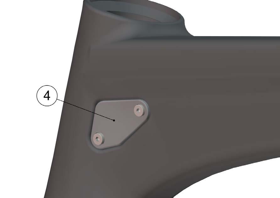
12 Rear brake installation 1. The rear brake cable should already be installed once you start to build the rear brake, if not, refer to the first chapter. 2. Apply Loctite to the brake pivot thread and bolt it into the frame. Description Part N Loctite Rear brake set Brake arm 2 Adjuster plate 3 Spring Adjuster bolt 3. Place the adjuster plate N 2 and screw in the M4 adjustment bolt N 4 (2). 2 The longer end of the spring faces towards the frame. 4. Apply grease to the spring and place it in the brake arm. The silver spring goes in the right side brake arm. The longer end of the spring faces towards the frame (2). 5. Install the brake arm on the frame (3). Tighten the M5 bolts to 4.5Nm (4). 6. Repeat steps 2 5 for the remaining brake arm. Note to use the dark spring for the left side brake arm.
13 11 / Run the cables through the required cable guides and grommets, and then install the cable guides on the frame to close the openings at the head tube (5). The 4 possible combinations are listed below. 5 Shorter screw Important: Note that the shorter screw (4.5mm) goes to the front, the longer screw (8mm) goes to the back. Longer screw Combinations / Description Required parts Part N A Mechanical (USA and EU standard) 1, 2, 3, B Mechanical (UK standard) 1, 2, 3, C Di2 (USA and EU standard) 5, 6, D Di2 (UK standard) 1, 4, Shifting cable grommet (spare part) Di2 grommet (spare part)
14 A B C D C C D D
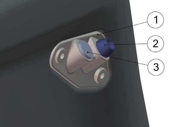
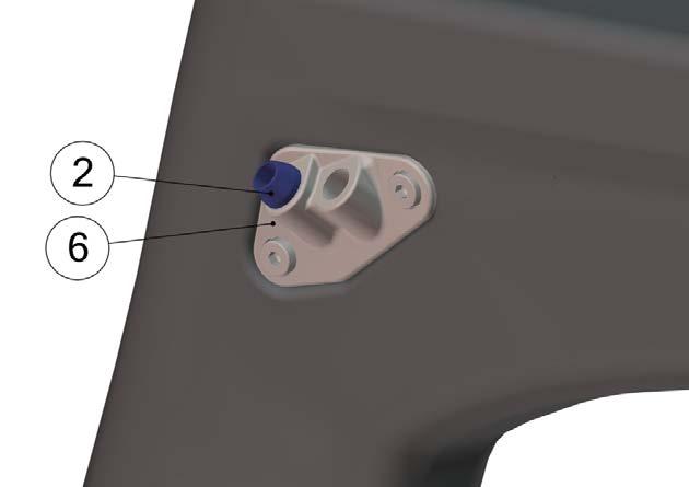
15 13 / Cut the brake cable housing 100mm from the cable guide and install the cable adjusters (N 8). Please refer to the official Shimano installation instructions Run the rear brake cable through the brake lever and the housing. 10. Slide the liner of the pipe over the brake cable (7). Then slide the pipe (N 1) over the brake cable and the liner (8) Install the pipe holder (N 2) and clamp the brake cable on the left brake arm with the T25 anchor bolt (N 3). Tighten to 6 Nm. 9 Description Part N Rear brake set Pipe 2 Pipe holder 3 Anchor bolt Shimano adjusters 12. Install the brake pads:
16 Brake pad configuration (front and rear) POS Description Part N 1 Brake pad 2 Socket 10mm 3 Socket 12mm Brake 4 Brake shoe shoe set: 5 Locker bolt Parabolic washer 7 Spacer 0.5mm 8 Spacer 1.2mm 9 Spacer 1.5mm 10 Spacer 2.0mm 11 Washer 12 Bolt M5 x 16 Depending on rim dimensions, the reach of the brake pads needs to be adjusted with spacers (7, 8, 9, 10). You can use the table below as a guide. Rim type Rim width Spacers per side (mm) Socket length Zipp 303/404/ Easton EC90 SL Mavic Cosmic Carbone SL Note to only put the one washer (N 11) between brake arm and brake shoe bolt (N 12). Please refer to the wheel manufacturer instructions for brake pad specification. 13. Adjust the spring tension (M4 adjustment bolts) to achieve symmetrical pull of the brake arms.
17 15 / 16 Front brake installation 1. Apply Loctite to the brake pivot thread and bolt it onto the fork. Description Part N Loctite Front brake complete set Brake arm 2 Adjuster plate 3 Spring Adjuster bolt 2. Place the adjuster plate (N 2) into the brake arm (N 1) and screw in the M4 adjustment bolt (N 4). The longer end of the spring goes into the fork 3. Apply grease to the spring (N 3) and place it in the brake arm. The silver colored spring goes into the right arm. The longest extension of the spring should point towards the fork. 4. Install the brake arm. Tighten the M5 bolt to 4.5Nm.
18 5. Apply Loctite to the brake pivot thread and bolt it onto the fork. 6. Repeat steps 1 4 for the second brake arm. Note to use the dark spring for the left side brake arm. 7. Cut a comfortable length of Shimano brake cable housing and run it through the top cap and the fork hinge. 8. Cut the brake cable housing 30mm from the top cap and install the cable adjusters. Please refer to the official Shimano installation instructions. 30mm 8 9. Run the front brake cable thru the housing.
19 17 / Slide the pipe noodle over the brake cable then slide the pipe over the brake cable and the noodle. 11. Install the pipe holder and clamp the brake cable on the left brake arm with the T25 anchor bolt. Tighten to 6Nm. 12. Install the brake pads: Refer to page 14 for pad and spacer specifications. 13. Install the brake cover.
20 14. Adjust the spring tension by using the M4 adjustment bolts until the brake arms rotate symmetrical.
21 Notes 19 / 20
22 Notes
23 Notes 21 / 22
24 Notes
25 23 / 24 Inhalt MONTAGEANLEITUNG Einleitung Kabelverlegung für mechanische Schaltung Kabelverlegung für Di2 Montage von Gabel und Steuersatz Montage von Sattelstütze und Sattelklemme Montage der Hinterbremse Bremsbelags-Konfiguration (vorne und hinten) Montage der Vorderradbremse Notizen
26
27 25 / 26 Einleitung Die BMC timemachine Rahmen und Komponenten wurden für bestmögliche Aerodynamik und Fahreigenschaften als System konzipiert. Integration ist eines der Kernelemente der timemachine, daher ist es wichtig zu verstehen, dass die meisten Komponenten des Rahmensets spezifisch für die timemachine TMR01 entwickelt wurden und ihre Funktion von der herkömmlicher Komponenten abweicht. Die BMC timemachine TMR01 nutzt die aktuellsten und hochwertigsten Technologien die in der Bikefertigung eingesetzt werden. Dazu gehören scharfkantige und dünnwandige Karbonkonstruktionen, die sorgfältig behandelt werden sollten um (manchmal unsichtbare) Beschädigungen zu verhindern. Aus diesen Gründen bitten wir Sie, die Instruktionen in diesem Benutzerhandbuch sorgfältig zu beachten. Fehler bei den mechanischen Arbeiten können Stürze verursachen, die zu schweren Verletzungen oder gar zum Tod führen können. Falls Sie nicht das geeignete Werkzeug besitzen oder keine ausreichende Erfahrung haben, um die in dieser Anleitung beschriebenen Arbeiten auszuführen, sowie wenn Sie weitere Informationen brauchen, wenden Sie sich bitte an Ihren BMC Händler.
28
29 27 / 28 Kabelverlegung für mechanische Schaltung 1. Führe die Kabelhülle für das hintere Schaltwerk durch den Rahmen, beginnend am Ausfallende (1). Die Kabelhülle sollte an der Öffnung auf der linken Seite des Steuerrohrs austreten (2) Führe die Kabelhülle für den Umwerfer durch die Öffnung auf der rechten Seite des Steuerrohrs in den Rahmen (3). Die Kabelhülle muss durch das Unterrohr und am Tretlager zur linken Seite den Rahmen wieder verlassen Installiere die Hüllenendhüle mit Nase auf die Kabelhülle und führe diese zurück in den Rahmen, so dass die Nase der Hüllenendhülse im Umwerfer-Kabelstopper sitzt (4). 4. Führe die Kabelhülle für die Hinterradbremse durch die Öffnung am Steuerrohr und das Unterrohr bis sie hinter dem Tretlager wieder austritt (5). Beachte, dass das Bremskabel rechts von den Schaltkabeln verlaufen muss. 5
30 Di2 Kabelverlegung Hinweis: Alle Informationen zur korrekten Installation der Di2-Kabel findest Du in der Shimano-Bedienungsanleitung. Diese Anleitung bezieht sich nur auf die korrekte Positionierung der Kabel im TMR01-Rahmen. 1. Benutze ein herkömmliches Schaltkabel, um das Di2-Kabel für das Schaltwerk durch die Kettenstrebe zu führen. Beginne am Ausfallende und führe das Kabel am Tretlager aus dem Rahmen raus. 2. Führe das Di2-Verzweigungskabel mithilfe eines Schaltkabels durch das Unterrohr. Beginne am Steuerrohr und führe das Kabel durch das Tretlager aus dem Rahmen.
31 29 / Führe das Di2-Umwerferkabel durch das Loch vor dem Umwerfersockel und wieder raus durch das Tretlager. 4. Installiere die Batterie in der Sattelstütze und führe das Kabel durch das Sitzrohr, bevor es ebenfalls am Tretlager austritt. interne Batterie 5. Verbinde alle Di2-Kabel mit der Verzweigung. 6. Schiebe die Kabel und die Verzweigung zurück in das Tretlager und Sitzrohr. 7. Installiere die Di2-Dichtungen.
32 Montage von Gabel und Steuersatz 1. Beachte, dass die Bremskabelhülle der Hinterradbremse vor der Gabel montiert werden muss. 2. Appliziere Fett auf die Lager (Nr. 3 und 4) und Lagersitze im Rahmen. Platziere die Lager im Rahmen. 3. Appliziere Fett auf den Gabelschaft, und schiebe danach die Gabel durch die Lager und das Steuerrohr. 4. Schiebe den Kompressionsring (Nr. 2) über den Gabelschaft. 5. Appliziere Fett auf die Kontaktfläche des Top Caps (Nr. 1) und schiebe dieses über die Gabel. Beschreibung Artikelnr. Steuersatz-Kit Top cap 2 Kompressionsring 3 Oberes Lager 4 Unteres Lager 5 Aero road Gabel teamred Aero road Gabel flame Aero road Gabel white Aero road Gabel stealth
33 31 / 32 Montage der Sattelstütze und Sattelklemme 1. Appliziere Fett auf die Kontaktfläche zwischen den beiden Keilen der Sattelklemme und auf die Aussenfläche. Die Kontaktfläche zwischen Sattelstütze und Sattelklemme muss fettfrei bleiben. 2. Baue die Sattelklemme zusammen (1) und platziere sie im Rahmen (2). 3. Für Di2 Schaltung, montiere die Batterie in der Sattelstütze. 4. Appliziere Karbon-Montagepaste auf die Sattelstütze und auf die Innenseite des Sitzrohres. 5. Führe die Sattelstütze in den Rahmen ein. 6. Montiere die Sattelbefestigung (Nr. 1). 7. Ziehe die Sattelklemme mit maximal 5Nm an (3). 8. Installiere den Gummistopfen (Nr. 3) um die Öffnung im Oberrohr zu schliessen Fett 5Nm 3 Beschreibung Artikelnr. 1 Sattelbefestigung Sattelklemme Gummistopfen Sattelstütze team red Sattelstütze flame Sattelstütze shark Sattelstütze white
34 Montage der Hinterradbremse 1. Das Hinterradkabel sollte bereits montiert sein, andernfalls folge der Anleitung im ersten Kapitel. 2. Trage etwas Loctite auf und montiere den Bremssockel. Beschreibung Artikelnr. Loctite Hinterradbremse Bremsarm 2 Einstellplatte 3 Feder Einstellschraube 3. Platziere die Einstellplatte (Nr. 2) und montiere die Einstellschraube (Nr. 4) (2). 2 Das The längere longer end Ende of der the Feder spring zeigt faces Richtung towards Rahmen. the frame. 4. Appliziere Fett auf die Feder und platziere sie im Bremsarm. Die silberne Feder gehört zum rechten Bremsarm. Das längere Ende der Feder zeigt Richtung Rahmen (2). 5. Installiere den Bremsarm am Rahmen (3). Ziehe die M5-Schraube mit 4.5Nm an (4). 6. Wiederhole die Schritte 2 5 für den verbleibenden Bremsarm. Beachte, dass die linke Seite mit der dunklen Feder montiert werden muss.
35 33 / Führe die Kabel durch die entsprechenden Kabelführungen und Dichtungen. Befestige danach die Kabelführungen am Rahmen um die Öffnungen zu schliessen (5). Die vier möglichen Kombinationen sind unten aufgeführt. 5 kürzere Schraube Wichtig: Die kürzere Schraube (4.5mm) muss vorne verwendet werden, die längere (8mm) hinten. längere Schraube Kombinationen/Beschreibung Benötigte Teile Artikelnr. A Mechanisch (USA und EU Standard) 1, 2, 3, B Mechanisch (UK Standard) 1, 2, 3, C Di2 (USA und EU Standard) 5, 6, D Di2 (UK Standard) 1, 4, Schaltkabel-Dichtung (Ersatzteil) Bremskabelstopfen (Ersatzteil) Di2 Dichtung (Ersatzteil)
36 A B C D C C D D
37 35 / Trenne die Kabelhülle 100mm entfernt von der Kabelführung ab und installiere den Kabeleinsteller (Nr. 8). Installiere ihn gemäss der Shimano-Anleitung Führe das Bremskabel durch den Bremshebel und die Kabelhülle. 10. Schiebe den Liner der Pipe über das Bremskabel (7). Schiebe danach die Pipe (Nr. 1) über das Bremskabel und den Liner (8) Montiere die Brücke (Nr. 2) und klemme das Bremskabel am linken Bremsarm mit der T25 Klemmschraube (Nr. 3). Ziehe diese mit 6Nm an. 9 Beschreibung Artikelnr. Hinterradbremse Pipe 2 Brücke 3 Klemmschraube Shimano Kabeleinsteller 12. Montiere die Bremsbeläge:
38 Bremsbelags-Konfiguration (vorne und hinten) POS Beschreibung Artikelnr. 1 Bremsbelag 2 Mutter 10mm 3 Mutter 12mm Brems- 4 Bremsbelagshalter belags- 5 Sicherungsschraube Kit 6 Konkave Unterlagsscheibe Spacer 0.5mm 8 Spacer 1.2mm 9 Spacer 1.5mm 10 Spacer 2.0mm 11 Unterlagsscheibe 12 Schraube M5 x 16 Abhänging von der Felgenbreite muss die Position der Bremsbeläge eingestellt werden durch die Verwendung von Spacern (7, 8, 9, 10). Entnehme die richtige Kombination der untenstehenden Tabelle. Felgentyp Felgenbreite Spacer pro Seite (mm) Mutterlänge Zipp 303/404/ Easton, EC90 SL Mavic Cosmic Carbone SL Beachte, dass nur die Unterlagsscheibe (Nr. 11) zwischen Bremsarm und Bremsbelagsschraube (Nr. 12) eingesetzt werden darf. Bitte folge den Angaben des Laufradherstellers bezüglich Bremsbelagswahl. 13. Stelle die Federspannung (mittels der M4-Einstellschraube) so ein, dass die Bremse symmetrisch funktioniert. Federspannung
39 37 / 38 Montage der Vorderradbremse 1. Trage Loctite auf und montiere den Bremssockel. Beschreibung Artikelnr. Loctite Vorderradbremse Bremsarm 2 Einstellplatte 3 Feder Einstellschraube 2. Platziere die Einstellplatte (Nr. 2) und montiere die Einstellschraube (Nr. 4). Das längere Ende der Feder muss zur Gabel zeigen. 3. Trage Fett auf und platziere die Feder (Nr. 3) im Bremsarm. Die silberne Feder gehört zum rechten Bremsarm. Das längere Ende muss zur Gabel zeigen. 4. Installiere den Bremsarm. Ziehe die M5-Schraube mit 4.5Nm an.
40 5. Wiederhole die Schritte 1 4 mit dem linken Bremsarm. Beachte, dass auf der linken Seite die dunkle Feder verwendet werden muss. 6. Führe ein grosszügig abgelängtes Stück Kabelhülle durch das Top Cap und die Gabel. 7. Trenne die Kabelhülle 30mm über dem Top Cap ab und installiere den Kabeleinsteller (Nr. 8) gemäss der Shimano-Anleitung. 30mm 8 8. Führe das Bremskabel durch die Kabelhülle.
41 39 / Schiebe den Liner der Pipe über das Bremskabel. Schiebe danach die Pipe über das Bremskabel und den Liner. 10. Montiere die Brücke und klemme das Bremskabel mit der T25 Klemmschraube am linken Bremsarm. Ziehe die Schraube mit 6Nm an. 11. Montiere die Bremsbeläge mit den Spacern gemäss Seite Installiere die Bremsabdeckung.
42 13. Stelle die Federspannung (mittels der M4-Einstellschraube) so ein, dass die Bremse symmetrisch funktioniert. Federspannung
43 Notizen 41 / 42
44 Notizen
45 Notizen 43 / 44
46 Notes
47 45 / 46 Sommaire INSTRUCTIONS DE MONTAGE Introduction Passage des câbles pour transmission mécanique Passage des câbles pour transmission Di2 Installation du jeu de direction et de la fourche Installation de la tige de selle Montage du frein arrière Configuration et réglage des patins (avant et arrière) Montage du frein avant Notes
48
49 47 / 48 Introduction Le cadre et les composants BMC timemachine TMR01 ont été conçus en tant que système pour offrir un très haut niveau de performance dynamique et aérodynamique. L intégration fait totalement partie de la performance du système, et il est nécessaire de comprendre que les composants du cadre ont été spécifiquement conçus pour le timemachine TMR01 et leur fonctionnement peut grandement différer de ce qu on trouve traditionnellement sur un vélo de route. Le BMC timemachine utilise les technologies les plus avancées en termes de fabrication de cadre de vélo, notamment au niveau des arêtes et parois des tubes carbone. Il doit donc être manipulé et entretenu avec soin pour prévenir tout dommage permanent et souvent invisible. Pour les raisons précédemment mentionnées, nous vous recommandons de suivre avec attention les instructions fournies dans ce manuel. Toute opération mécanique incorrecte sur votre vélo pourrait mener à des dommages importants, provoquer une chute et des blessures potentiellement mortelles. Si vous n avez pas l équipement ou les compétences nécessaires pour exécuter les instructions ci-après, ou si vous désirez d avantage d information, veuillez contacter votre revendeur BMC pour l entretien de votre vélo.
50

.")
.")

. 4.")
51 49 / 50 Passage des cables pour transmission mécanique 1. Insérer la gaine de dérailleur arrière depuis la patte de cadre droite, puis la pousser dans le cadre (1). Faire sortir la gaine par l ouverture située au niveau de la douille de direction (2) Insérer la gaine de dérailleur avant depuis l ouverture droite du tube de direction (3). La pousser dans le tube diagonal et la faire sortir par l ouverture du boitier de pédalier Installer l arrêt de gaine à son extrémité, puis refaire passer la gaine dans le cadre afin de l insérer dans l arrêt de câble de dérailleur avant (4). 4. Insérer la gaine de frein arrière depuis l ouverture du jeu de direction, la pousser dans le tube diagonal et la faire sortir par l ouverture située derrière le boitier de pédalier (5). Noter que la gaine de frein arrière doit passer à droite des autres câbles déjà installés. 5


52 Passage des câbles pour transmission Di2 Note: Pour tout ce qui concerne l installation d un groupe Di2, merci de se référer aux instructions de montage fournies par Shimano. Ce chapitre n offre que les instructions nécessaires à l installation des câbles Di2 dans votre cadre Timemachine TMR Utiliser un câble de frein pour aiguiller le câble électrique de dérailleur arrière Di2 à travers les bases. Entrer par la patte de cadre droite et sortir par le côté droit du boitier de pédalier. 2. Utiliser un câble de frein pour aiguiller le câble électrique principal dans le tube diagonal. Entrer par l ouverture de la douille de direction et sortir par le boitier de pédalier côté droit.


53 51 / Insérer le câble électrique du dérailleur avant Di2 par l ouverture située contre la patte de dérailleur avant. Sortir par le côté droit du boitier de pédalier. 4. Monter la batterie intégrée dans la tige de selle, puis guider le câble électrique depuis la batterie jusqu au boitier de pédalier. Sortir par le côté droit du boitier de pédalier. Batterie intégrée 5. Réaliser les connections entre les différents éléments Di2 au niveau du boitier de pédalier, selon les instructions officielles fournies par Shimano. 6. Repousser les câbles et leurs jonctions à l intérieur du boitier de pédalier et dans la partie basse du tube de selle. 7. Installer les petits guide-câbles caoutchouc «Di2 grommets».

54 Installation du jeu de direction et de la fourche 1. Noter que la gaine de frein arrière doit être installée dans le cadre avant d assembler la fourche sur le cadre. Si ce n est pas le cas, se référer au premier chapitre. 2. Appliquer de la graisse sur les roulements (N 3 et 4) et dans les logements du cadre. Positionner les roulements dans le cadre. 3. Appliquer de la graisse sur la partie basse du pivot de fourche, puis l insérer dans le cadre à travers les roulements et la douille de direction. 4. Installer la bague fendue de compression (N 2) sur le pivot de fourche. 5. Appliquer de la graisse sur la partie supérieure de l extension de la fourche, puis installer le capot de jeu de direction (N 1) sur le pivot de fourche et sur l extension de fourche. Description Pièce N Jeu de direction complet Capot de jeu de direction 2 Bague de compression 3 Roulement supérieur 4 Roulement inférieur 5 Fourche aéro teamred Fourche aéro flame Fourche aéro white Fourche aéro stealth
 puis le positionner dans le logement du cadre (2). 3. Pour les transmissions Di2, monter la batterie interne dans la tige de selle. 4.")
. 7. Serrer la tige de selle au couple de 5Nm maximum (3). 8. Installer le bouchon caoutchouc (N 3) sur le tube supérieur.")
55 53 / 54 Installation de la tige de selle 1. Appliquer de la graisse sur les pièces du serrage de selle. Attention, ne pas graisser la surface en contact avec la tige de selle. 2. Assembler le serrage de la tige (1) puis le positionner dans le logement du cadre (2). 3. Pour les transmissions Di2, monter la batterie interne dans la tige de selle. 4. Appliquer de la pâte de friction pour carbone sur la partie inférieure de la tige de selle ainsi que dans la partie supérieure du tube de selle. 5. Insérer la tige de selle dans le tube de selle. 6. Installer les pièces de serrage de la selle (N 1). 7. Serrer la tige de selle au couple de 5Nm maximum (3). 8. Installer le bouchon caoutchouc (N 3) sur le tube supérieur Graisse 5Nm 3 Description Pièce N 1 Kit serrage de selle Kit serrage tige de selle Bouchon caoutchouc Tige de selle team red Tige de selle flame Tige de selle shark Tige de selle white

56 Installation du frein arrière 1. Noter que la gaine de frein arrière doit être installée dans le cadre avant de commencer le montage des freins. 2. Appliquer du produit frein filet sur le pas de vis des tasseaux de frein, puis les visser dans le cadre. Description Pièce N Loctite Kit frein arrière Etrier de frein 2 Plaque de réglage 3 Ressort Vis de réglage 3. Placer la plaque de réglage N 2 dans l étrier de frein N 1 et visser la vis de réglage N 4 (2). 2 The La longer plus end longue of the spring extension faces du towards ressort the doit frame. pointer vers le cadre. 4. Appliquer de la graisse sur le ressort et le placer dans l étrier de frein. Le ressort argenté se place dans l étrier de droite. La plus longue extension du ressort doit pointer vers le cadre (2). 5. Installer l étrier de frein sur le cadre (3). Visser et serrer les vis M5 au couple de 4.5Nm (4). 6. Répéter les opérations 2 5 pour le second étrier de frein. Noter que le ressort noir se place dans l étrier de frein côté gauche.


 1, 2, 3, 6 212487 B Mécanique")
57 55 / Passer les câbles à travers les guide-câbles, puis visser les guide-câbles sur le cadre, des deux côtés de la douille de direction (5). Les 4 configurations possibles de guide-câbles sont détaillées ci-dessous. 5 Vis plus courte Important: Noter que la vis la plus courte (4.5mm) se place à l avant du guide-câbles, la vis la plus longue (8mm) se place vers l arrière du cadre. Vis plus longue Configurations Pièces nécessaires Pièce N A Mécanique (Standard EU et USA) 1, 2, 3, B Mécanique (Standard UK) 1, 2, 3, C Di2 (Standard EU et USA) 5, 6, D Di2 (Standard UK) 1, 4, Joint caoutchouc (pièce détachée) Bouchon (pièce détachée) Joint Di2 (pièce détachée)


58 A B C D C C D D

59 57 / Couper la gaine de frein arrière environ 100mm après les guide-câbles et installer les douilles de réglage N 8 (6). Pour l utilisation et l installation des douilles, se référer aux instructions spécifiques Shimano Enfiler le câble de frein arrière à travers le levier de frein au guidon et à travers la gaine. 10. Enfiler d abord le tube plastique sur le câble de frein (7). Puis insérer le coude métallique par-dessus le tube plastique (8) Installer la bride de maintien du coude (N 2) et serrer le câble du côté gauche à l aide de la vis de blocage à empreinte Torx T25 (N 3). Serrer au couple de serrage de 6Nm. 9 Description Pièce N Kit frein arrière Coude 2 Bride de maintien 3 Vis de blocage Douille de réglage 12. Installer les patins de frein:
60 Configuration et réglage des patins (avant et arrière) POS Desc. Pièce N 1 Gomme de frein 2 Douille 10mm 3 Douille 12mm Kit 4 Patin de frein patin de frein: 5 Vis de blocage Rondelle concave 7 Entretoise 0.5mm 8 Entretoise 1.2mm 9 Entretoise 1.5mm 10 Entretoise 2.0mm 11 Rondelle 12 Vis M5 x 16 Selon la largeur des jantes installées et pour un meilleur fonctionnement de l étrier de fein, la distance des patins à la jante doit être modifiée à l aide des entretoises (7, 8, 9, 10). Le tableau ci-dessous est donné à titre indicatif. Type de jante Largeur de jante Entretoises à installer, pour chaque côté (mm) Douille à installer (mm) Zipp 303/404/ Easton, EC90 SL Mavic Cosmic Veiller à n installer qu une seule rondelle (N 11) entre l étrier de frein et sa vis de serrage (N 12). Pour le choix des gommes, se référer aux instructions du constructeur des roues. 13. Ajuster la tension des ressorts (vis M4) pour obtenir un fonctionnement symétrique du frein. la tension du ressort


61 59 / 60 Installation du frein avant 1. Appliquer du frein filet sur la partie filetée du tasseau de frein et visser dans la fourche. Description Pièce N Loctite Kit complet frein avant Etrier de frein 2 Plaque de réglage 3 Ressort Vis de réglage 2. Placer la plaque de réglage (N 2) dans l étrier de frein (N 1) puis visser la vis de réglage (N 4). L extension la plus longue doit pointer vers le cadre. 3. Appliquer de la graisse sur le ressort (N 3) et le placer dans l étrier de frein. Le ressort argenté se place dans l étrier côté droit. L extension la plus longue doit pointer vers le cadre.


62 4. Installer l étrier de frein sur le cadre. Serrer au couple de 4.5Nm. 5. Répéter les opérations 1 4 pour le second étrier de frein. Le ressort noir se place dans l étrier côté gauche. 6. Couper une longueur de 30cm de gaine de frein Shimano et la faire courir dans le capot de jeu de direction et dans l extension de la fourche. 7. Ajuster la longueur de la gaine pour avoir environ 30mm depuis la sortie du capot de jeu de direction. Installer ensuite les douilles de réglage (N 8) en se référant aux instructions fournies par Shimano. 30mm 8 8. Enfiler le câble de frein à travers le levier au guidon, puis dans sa gaine.


.")
63 61 / Enfiler d abord le tube plastique sur le câble de frein. Puis insérer le coude métallique par-dessus le tube plastique. 10. Installer la bride de maintien du coude puis tendre et serrer le câble du côté gauche à l aide de la vis de blocage à empreinte Torx T25 (N 3). Serrer au couple de serrage de 6Nm. 11. Installer les patins de feins: Se référer à la page 66 pour le réglage des patins. 12. Installer le capot de frein avant.


64 13. Ajuster la tension des ressorts (vis M4) pour obtenir un fonctionnement symétrique du frein. la tension du ressort
65 Notes 63 / 64
66 Notes
67 Notes 65 / 66
68
69
70 BMC TRADING AG Sportstrasse 49 CH-2540 Grenchen Switzerland
E-116 Assembly Guide
 E-116 Assembly Guide Table of Contents Overview of the assembly.... 2 1. Cable housing installation.... 3 2. Front brake installation.... 4 3. Rear brake installation... 5-6 4. Seatpost installation....
NITROGEN: ASSEMBLY GUIDE
 NITROGEN: ASSEMBLY GUIDE Valid for MY2016 Nitrogen Revision 3.0-04-01-2016 NITROGEN: Table of contents Overview of the assembly..........................2-3 1. Frame inspection........................4
E-118 Assembly Guide
 E-118 Assembly Guide Table of Contents Overview of the assembly.... 2 1. Fork installation.... 3-4 2. Cable housing installation.... 5 3. Handlebar installation... 6 4. Front brake installation.... 7-8
TABLE OF CONTENTS FRAME FEATURES INTRODUCTION
 S3 DISC MANUAL TABLE OF CONTENTS Introduction...1 Frame Features...2 Fork Preparation...3 Small Parts...5 Frame Preparation...6 Brake Housing Installation...7 Mechanical Cable Routing...9 Electric Cable
and welcome to the world of Life Fitness and the Life Fitness 9500HR / 9100 / 8500 Recumbent Exercise Bikes.
 ([HUFLVH%LNH $66(0%/
NITROGEN DISC 286A: ASSEMBLY GUIDE
 NITROGEN DISC 286A: ASSEMBLY GUIDE Valid for MY2019 Nitrogen Disc 286A Revision 1.0-07-26-2018 NITROGEN DISC 286A: Table of Contents 1. Tools Needed and First Aid Kit...3 2. Frameset inspection...4 3.
Publics and Dealers Prices List ATOMZ//UN March 2010
 Publics and Dealers Prices List ATOMZ//UN March 2010 NOUVEAUTES 2010 EN VERT NEWS 2010 IN GREEN NOUVEAUTES 2010 EN VERT NEWS 2010 IN GREEN Page 1/7 ATOMZ QUARK II 26" ATOMZ QUARK II 26" AVRIL//APRIL VT0QUARK26DSGR
R5 RIM MANUAL EN. Version 1 I
 R5 RIM MANUAL EN Version 1 I 28.04.2017 TABLE OF CONTENTS Introduction...1 Frame Features...2 Fork Preparation...3 Small Parts...5 Frame Preparation...6 Mechanical Cable Routing...7 Electric Cable Routing...9
BODY-CARCASSE (C)2011
2011") BODY-CARCASSE ITEM CODE REF. NO DESCRIPTION DESCRIPTION 1 3002102 YC1-3002102 Wheel support Support de roue 2 4398848 GB/T96 Washer 6 Rondelle 6 3 4398108 GB/T70.1 Self-tapping screw M6X16 Vis auto-taraudeuse
BODY-CARCASSE ITEM CODE REF. NO DESCRIPTION DESCRIPTION 1 3002102 YC1-3002102 Wheel support Support de roue 2 4398848 GB/T96 Washer 6 Rondelle 6 3 4398108 GB/T70.1 Self-tapping screw M6X16 Vis auto-taraudeuse
FRAME FEATURES TABLE OF CONTENTS INTRODUCTION
 R3 MANUAL TABLE OF CONTENTS Introduction...1 Frame Features...2 Fork Preparation...3 Small Parts...5 Frame Preparation...6 Mechanical Cable Routing...7 Electric Cable Routing...9 Seatpost Assembly & Installation...11
STIGA SNOW FOX (2018) Spare parts list Reservdelar Repuestos Ersatzteile Pièces détachées Reserve onderdelen Catalogo ricambi
 Spare parts list Reservdelar Repuestos Ersatzteile Pièces détachées Reserve onderdelen Catalogo ricambi") STIGA 18-2869-32 Spare parts list Reservdelar Repuestos Ersatzteile Pièces détachées Reserve onderdelen Catalogo ricambi Use ST. S.p.A. Genuine Spare Parts specified in the parts list for repair and/or
STIGA 18-2869-32 Spare parts list Reservdelar Repuestos Ersatzteile Pièces détachées Reserve onderdelen Catalogo ricambi Use ST. S.p.A. Genuine Spare Parts specified in the parts list for repair and/or
KRYPTON X ROAD : ASSEMBLY GUIDE
 KRYPTON X ROAD : ASSEMBLY GUIDE Revision 3.0-06-01-2016 KRYPTON X ROAD : Table of contents Assembly overview.........................2 1. Frame inspection........................3 2. Headset installation.......................4
R3 RIM MANUAL EN. Version 1 I
 R3 RIM MANUAL EN Version 1 I 07.02.2017 TABLE OF CONTENTS Introduction...1 Frame Features...2 Fork Preparation...3 Small Parts...5 Frame Preparation...6 Mechanical Cable Routing...7 Electric Cable Routing...9
STIGA. Park 340 PWX (2018) 2F /S18. Spare parts list Reservdelar Repuestos Ersatzteile Pièces détachées Reserve onderdelen Catalogo ricambi
 2F /S18. Spare parts list Reservdelar Repuestos Ersatzteile Pièces détachées Reserve onderdelen Catalogo ricambi") STIGA 2F6130621/S18 Spare parts list Reservdelar Repuestos Ersatzteile Pièces détachées Reserve onderdelen Catalogo ricambi Use ST. S.p.A. Genuine Spare Parts specified in the parts list for repair and/or
STIGA 2F6130621/S18 Spare parts list Reservdelar Repuestos Ersatzteile Pièces détachées Reserve onderdelen Catalogo ricambi Use ST. S.p.A. Genuine Spare Parts specified in the parts list for repair and/or
GALLIUM PRO 210A: ASSEMBLY GUIDE
 GALLIUM PRO 210A: ASSEMBLY GUIDE Revision 5.0-05-23-2017 GALLIUM PRO 210A: Table of contents Assembly overview...2-3 1. Frame inspection...4 2. Headset installation...5 3. Cables & housing installation...6-9
STIGA. Park 520 P (2018) 2F /S16. Spare parts list Reservdelar Repuestos Ersatzteile Pièces détachées Reserve onderdelen Catalogo ricambi
 2F /S16. Spare parts list Reservdelar Repuestos Ersatzteile Pièces détachées Reserve onderdelen Catalogo ricambi") STIGA 2F6220611/S16 Spare parts list Reservdelar Repuestos Ersatzteile Pièces détachées Reserve onderdelen Catalogo ricambi Use ST. S.p.A. Genuine Spare Parts specified in the parts list for repair and/or
STIGA 2F6220611/S16 Spare parts list Reservdelar Repuestos Ersatzteile Pièces détachées Reserve onderdelen Catalogo ricambi Use ST. S.p.A. Genuine Spare Parts specified in the parts list for repair and/or
2019 MADONE ASSEMBLY MANUAL
 2019 MADONE ASSEMBLY MANUAL 2019 MADONE Rim brakes and Di2 drivetrain Rim brakes and mechanical drivetrain Disc brakes and Di2 drivetrain Disc brakes and mechanical drivetrain TABLE OF CONTENTS Common
GALLIUM PRO: ASSEMBLY GUIDE
 GALLIUM PRO: ASSEMBLY GUIDE Revision 2.0-04-08-2016 GALLIUM PRO : Table of contents Assembly overview..........................2-3 1. Frame inspection........................4 2. Headset installation.......................5
E-117 TRI: ASSEMBLY GUIDE
 E-117 TRI: ASSEMBLY GUIDE Valid for MY2016 E-117 Tri Revision 8.0-07-08-2016 E-117 TRI: Table of Contents 1. Tools Needed & First Ait Kit..........................2 2. Fitting / Stack & Reach.....................3
GALLIUM PRO 259A & 259B: ASSEMBLY GUIDE
 GALLIUM PRO 259A & 259B: ASSEMBLY GUIDE GALLIUM PRO 259A & 259B: Table of Contents 1. Tools Needed and First Aid Kit... 3 2. Sizing Chart... 4 3. Trouble-shooting / Tips... 5 4. Seat Post Collar Assembly...
SECTION 1 UNPACKING INSTRUCTIONS
 ANDEAN USER GUIDE SECTION 1 UNPACKING INSTRUCTIONS 2 REMOVE PART BOX, ACCESSORY BOX AND SADDLE AND SEATPOST. SET ACCESORIES AND SEAT ASIDE FOR FINAL. PARTS BOX ACCESORY BOX 3 UNSTRAP WHEEL BLOCKS AND HANDLEBAR
TABLE OF CONTENTS INTRODUCTION
 R3 DISC MANUAL TABLE OF CONTENTS Introduction... 1 Frame Features... 2 Fork Preparation... 3 Small Parts... 5 Frame Preparation... 6 Brake Housing Installation... 7 Mechanical Cable Routing... 9 Electric
TIMEMACHINE. Assembly Manual
 TIMEMACHINE Assembly Manual TIMEMACHINE Assembly Instruction Manual The new Timemachine 01 represents the pinnacle of functional integration, aerodynamic form and rider-focused fit. By patiently following
GALLIUM: ASSEMBLY GUIDE
 GALLIUM: ASSEMBLY GUIDE Revision 2.0-04-08-206 GALLIUM: Table of contents Assembly overview..........................2. Frame inspection........................3 2. Headset installation.......................4
2019 MADONE ASSEMBLY MANUAL
 2019 MADONE ASSEMBLY MANUAL 2019 MADONE Rim brakes and Di2 drivetrain Disc brakes and Di2 drivetrain Rim brakes and mechanical drivetrain Disc brakes and mechanical drivetrain TABLE OF CONTENTS Common
FACTORBIKES.COM. Assembly Manual DISC V1.05
 FACTORBIKES.COM V1.05 Introduction I Limited Lifetime Warranty On Bicycles And Framesets I Necessary Tools 01 Instructions 01 1 Seatpost 01 2 Cut the cable housing to the correct length 03 3 Di2 Cable
FACTORBIKES.COM. Assembly Manual V2.20
 FACTORBIKES.COM V2.20 Introduction I Limited Lifetime Warranty On Bicycles And Framesets I Necessary Tools 01 Instructions 01 1 Seatpost 01 2 Di2 Cable Routing 03 3 Fork - Headset Barstem 05 4 Cutting
GALLIUM CS 281A: ASSEMBLY GUIDE. Revision Valid for MY2019 Gallium CS
 GALLIUM CS 281A: ASSEMBLY GUIDE Revision 0.0-2018-05-04 - Valid for MY2019 Gallium CS GALLIUM CS 281B: ASSEMBLY GUIDE Revision 0.0-2018-05-04 - Valid for MY2019 Gallium CS GALLIUM CS 281A / 281B: Table
KRYPTON X ROAD : ASSEMBLY GUIDE
 KRYPTON X ROAD : ASSEMBLY GUIDE KRYPTON X ROAD : Table of contents Assembly overview.........................2 1. Frame inspection........................3 2. Headset installation.......................4
MA NUAL 795 BLADE RS
 MA NUAL 79 BLADE RS CONGRATULATIONS! IMPORTANT INFORMATION INTRODUCTION TO THE PRODUCT PRE-ASSEMBLY CHECK FULL 79 BLADE RS ROUTING Rear derailleur hanger Mechanical/electronic routing configuration Routing
Rocky Mountain Instinct / Pipeline Alloy Frame Assembly Guide. Date: April 7, 2017
 Rocky Mountain Instinct / Pipeline Alloy Frame Assembly Guide Date: April 7, 2017 1 Table of Contents Front Triangle Preparation... 4 Parts Needed... 4 Instructions... 4 Chain Stay Preparation... 6 Parts
R5 DISC MANUAL EN. Version 1 I
 R5 DISC MANUAL EN Version 1 I 30.04.2017 TABLE OF CONTENTS Introduction...1 Frame Features...2 Fork Preparation...3 Small Parts...5 Frame Preparation...6 Brake Housing Installation...7 Mechanical Cable
FRAME FEATURES TABLE OF CONTENTS INTRODUCTION. A guide to your Cervélo C Series frame.
 C SERIES MANUAL TABLE OF CONTENTS Introduction...1 Frame Features...2 Fork Preparation...3 Small Parts...5 Frame Preparation...6 Brake Housing Installation...7 Mechanical Cable Routing...9 Electric Cable
E-119 TRI: ASSEMBLY GUIDE
 E-119 TRI: ASSEMBLY GUIDE Valid for MY2016 E-119 Tri Revision 12.0-07-08-2016 E-119 TRI: Table of Contents 1. Tools Needed & First Ait Kit..........................2 2. Fitting / Stack & Reach.....................3
RADON 237A: ASSEMBLY GUIDE. Revision Valid for MY2017 Radon
 RADON 237A: ASSEMBLY GUIDE Revision 3.0-05-29-2017 - Valid for MY2017 Radon RADON 237A: Table of Contents 1. Tools Needed and First Aid Kit... 3 2. Sizing Chart... 4 3. Seat Post Collar Assembly... 5 4.
1 Electronic Wiring. Felt IA Owner s Manual. CalPac / AeroPac Installation... Pg Note:
 Felt IA Owner s Manual 1 2 3 4 5 6 7 8 Introduction................. Pg. 3 Fit Chart................... Pg. 4 Electronic Wiring.............. Pg. 5-15 Mechanical Cabling............. Pg. 16-24 Fork Installation...............
Shimano Di2 Installation on S5
 Installing Shimano Dura Ace Di2 Shifting Systems Note these instructions and pictures are for assembling the Shimano Dura Ace Di2 system (Internal Spec) on the Cervélo S5 frame. The Shimano Ultegra Di2
Electronic Drivetrain Cabling Guide R1.0
 Electronic Drivetrain Cabling Guide R1.0 Congratulations on the purchase of your new PARLEE Altum! The Altum is our most advanced model to date, delivering race ready performance with our signature PARLEE
Betriebsanleitung Operating manual
 BD_BE 1250 b Kraft Druck Temperatur Schalten Service Force Pressure Temperature Switch Service Betriebsanleitung Operating manual P1123 P1546 P1545 Spezialschlüssel zur Montage von Doppeldruckmessgeräten
BMC Spezifikationen Spécifications Specifications Specifiche
 BMC 2012 Spezifikationen Spécifications Specifications Specifiche road impec series [SWA] [SWA] [SWA] [SWA] [SWA] [SWA] [SWA] road race series [SWA] [SWA] [SWA] teammachine SLR01 Campagnolo SR [SWA] TCC
Installation/User s Guide Guide de l Utilisateur Installations- /Gebrauchsanleitung. U.S. Patent No. 7,922,246. Patent Pending
 Installation/User s Guide Guide de l Utilisateur Installations- /Gebrauchsanleitung For International Markets U.S. Patent No. 7,922,246 Patent Pending 2 Table of Contents Page General Information... 3
Rear Drive System SERVICE INSTRUCTION. Specifications SI-R670B
 - SERVICE INSTRUCTION SI-R670B t Rear Drive System Before use, read these instructions carefully, and follow them for correct use. In order to realize the best performance, we recommend that the following
SCOTT PLASMA 4 BIKE OWNER S MANUAL
 www.scott-sports.com SCOTT PLASMA 4 All rights reserved 2014 SCOTT Sports SA SCOTT Sports SA 17 Route du Crochet 1762 Givisiez Switzerland BIKE OWNER S MANUAL 2015 Distribution: SSG (Europe) Distribution
GALLIUM PRO : ASSEMBLY GUIDE
 GALLIUM PRO : ASSEMBLY GUIDE GALLIUM PRO : Table of contents Assembly overview..........................2-3 1. Frame inspection........................4 2. Headset installation.......................5
E-trike Li Assembly Guide
 PREPARATION 1. Read this assembly manual BEFORE commencing assembly. 2. Carefully remove all the components and packaged hardware from the shipping boxes. 3. Unpack the contents of the large double box
CRUZBIKE Quest 2.0 Assembly
 CRUZBIKE Quest 2.0 Assembly CRUZBIKE Quest 2.0 Assembly... 1 General notes on assembly... 2 Un box and evaluate the frame and major parts... 2 Unfold the rear swing arm and arrange the frame... 3 Rear
ELECTRON PRO 245A: ASSEMBLY GUIDE. Revision Valid for MY2017 Electron Pro
 ELECTRON PRO 245A: ASSEMBLY GUIDE Revision 2.0 04-19-2017 Valid for MY2017 Electron Pro ELECTRON PRO 245A: Table of Contents 1. Tools Needed and First Aid Kit...3 2. Specifications...4 3. Configurations...5
E-119 TRI+ 284A: ASSEMBLY GUIDE
 E-119 TRI+ 284A: ASSEMBLY GUIDE Valid for MY2019 E-119 Tri+ Revision 1.0-07-18-2018 E-119 TRI+ 284A: Table of Contents 1. Tools Needed & First Ait Kit..........................2 2. Fitting / Stack & Reach.....................3
Rev B. Mar 23, 2011 Page 1 of 5
 Rev B. Mar 23, 2011 Page 1 of 5 www.topendwheelchair.com Invacare Top End Sports and Recreation Products (800) 532-8677 (727) 522-8677 fax: (727) 522-1007 Force G: Fork Assembly 1 1166257 1 Fork, Force
TECHNICAL NOTE. Tightening of the screws holding the rear wheels callipers on the J-RO
 BT-JRO-912-914-001 Tightening of the screws holding the rear wheels callipers on the J-RO COMPULSARY Employed symbolic: This note uses three levels of warnings: DANGER, CAUTION and NOTE, associating three
ELECTRON PRO: ASSEMBLY GUIDE. Revision Valid for MY2017 Electron Pro
 ELECTRON PRO: ASSEMBLY GUIDE Revision 1.0 10-20-2016 Valid for MY2017 Electron Pro ELECTRON PRO: Table of Contents 1. Tools Needed and First Aid Kit...3 2. Specifications...4 3. Configurations...5 4. Geometry...7
E-80 : ASSEMBLY GUIDE
 E-80 : ASSEMBLY GUIDE E-80 : Table of contents Assembly overview..........................2 1. Frame inspection........................3 2. Cable housing installation.......................4-7 3. Brakes
PRECAUTION INTENDED USE OF THIS MANUAL INTRODUCTION AKING CARE OF
 Table of Contents 1 INTRODUCTION INTDED USE OF THIS MANUAL PRECAUTION TAKING CARE OF YOUR COMPOSITE BICYCLE 5 6 OVERDRIVE HEADSET INSTRUCTION COMPOSITE FRONT FORK 5 7 SPEEDCONTROL BRAKES 6 8 9 10 11 1
Rear Drive System SERVICE INSTRUCTIONS SI-R920A WARNING. Note Always be sure to use the sprocket set bearing the same group
 - SERVICE INSTRUCTIONS SI-R90A t Rear Drive System Before use, read these instructions carefully, and follow them for correct use. WARNING Use neutral detergent to clean the chain. Do not use alkali-based
NOAH FAST. frame passport
 frame passport Type: 7DC last update: /08/05 INDEX 0. UPDATES... 3. GENERAL... 3.. Description... 3.. Part codes... 3. MATERIAL... 3 3. WEIGHT... 3 3.. Frame... 3 3.. Fork... 3 4. GEOMETRY... 4 5. CABLE
RECOMMANDATION GÉNÉRALE D UTILISATION PORTE-CLIPS PORTE-LANGUETTES 16 VOIES HYBRIDE
 GENERAL UTILIZATION RECOMMENDATION RECEPTACLE HOUSING 03 Juillet 07 Rév. C 1. INTRODUCTION 1. INTRODUCTION 1.1. Présentation du produit 1.1 Product description HOUSING SLIDE "DL" Figure 1 Le Porte-clips
comfort without compromising on performance and to fit your various needs on touring,
 Congratulations on your purchase of Goal-26X. Goal-26X is made to enhance comfort without compromising on performance and to fit your various needs on touring, shopping and communicating. Let s have fun
ALPINA AT4 98 HCB (2018) 2T /11. Spare parts list Reservdelar Repuestos Ersatzteile Pièces détachées Reserve onderdelen Catalogo ricambi
 2T /11. Spare parts list Reservdelar Repuestos Ersatzteile Pièces détachées Reserve onderdelen Catalogo ricambi") ALPINA 2T0620306/11 Spare parts list Reservdelar Repuestos Ersatzteile Pièces détachées Reserve onderdelen Catalogo ricambi Use ST. S.p.A. Genuine Spare Parts specified in the parts list for repair and/or
ALPINA 2T0620306/11 Spare parts list Reservdelar Repuestos Ersatzteile Pièces détachées Reserve onderdelen Catalogo ricambi Use ST. S.p.A. Genuine Spare Parts specified in the parts list for repair and/or
Rocky Mountain Instinct / Pipeline Frame Assembly Guide. Date: March 31, 2017
 Rocky Mountain Instinct / Pipeline Frame Assembly Guide Date: March 31, 2017 1 Table of Contents Front Triangle Preparation... 4 Parts Needed... 4 Instructions... 4 Chain Stay Preparation... 6 Parts Needed...
SI-F971A. 9-speed super narrow chain such as CN-7700 / CN-HG92 8- / 7- / 6-speed narrow chain such as CN-HG50 / CN-IG51
 SERVICE INSTRUCTIONS SI-F971A Front Drive System Before use, read these instructions carefully, and follow them for correct use. WARNING Use neutral detergent to clean the chain. Do not use alkali-based
GENERAL INFO SCOTT 2011 BIKE OWNERS MANUAL
 SCOTT 2011 BIKE OWNERS MANUAL A INFO SCOTT SPORTS SA 17 RTE DU CROCHET 1762 GIVISIEZ SWITZERLAND 2009 SCOTT SPORTS SA, ALL RIGHTS RESERVED SCOTT-SPORTS.COM CONTENT Congratulations P. 004 Bicycle Safety
ROAD DISC TECHNICAL MANUAL
 ROAD DISC TECHNICAL MANUAL INTRODUCTION Congratulations on purchasing a Felt disc brake equipped road bike. As with all of our bikes and components, our aim is to provide the rider with the best product
Rev C Force 2 Parts Book Page 1 of 7 Top End
 1181378 Rev C.2016.03.14 Force 2 Parts Book Page 1 of 7 Force 2: Fork Assembly Date: Customer: Ship to: PER BIKE DESCRIPTION 1 1166391 1 Fork, Force 2 (incl: fork, 4 bolts) -Serial# Required- Red Blue
VLT. VLT Series Bookstyle... page 3. Compact IP page 9. Compact IP page 23 *MI50L151* Instruction
 VLT Instruction Drives and Controls APPLICATION OPTION VLT Series 5000 Montering, Mounting, Montage, Installation Bookstyle... page 3 Compact IP 20... page 9 Compact IP 54... page 23 Advarsel! Applikations
Rocky Mountain Element Technical Manual. Rev B
 Rocky Mountain Element Technical Manual Rev B 1 Table of Contents Materials Required... 3 Suspension Pivot Torque Guide... 4 Small Parts Torque Guide... 5 Assembly Instructions... 6 1) Bearing Installation...
SUPPLEMENTARY MANUAL
 SUPPLEMENTARY MANUAL TABLE OF CONTENTS Introduction...1 Features diagram...2 Getting started...3 Fork...3 Derailleur cables...3 Rear brake...9 Replaceable Rear Derailleur mount...10 Using your Cervélo
Reinforced connecting pin. Silver. 6.5mm. Black. 7.1mm
 - SERVICE INSTRUCTIONS SI-R70C t Rear Drive System Before use, read these instructions carefully, and follow them for correct use. WARNING Use neutral detergent to clean the chain. Do not use alkali-based
INTENDED USE OF THIS MANUAL
 Table of Contents 1 INTRODUCTION... 2 2 INTENDED USE OF THIS MANUAL... 2 3 PRECAUTION... 2 4 TAKING CARE OF YOUR COMPOSITE BICYCLE... 3 5 OVERDRIVE 2 HEADSET INSTRUCTION... 4 6 COMPOSITE FRONT FORK...
PRINTED: 3/29/2016 1:46:12 PM - THIS DOCUMENTATION IS OBSOLETE AFTER: 3/30/2016 1:46 PM
 1181377 Rev H.2016.03.14 Force G Parts Book Page 1 of 7 Top End INTED: 3/29/2016 1:46:12 PM - THIS DOCUMENTATION IS OBSOLETE AFTER: 3/30/2016 1:46 PM INTED: 3/29/2016 1:46:12 PM - THIS DOCUMENTATION IS
Assembly Tools. Assembly will take 1-2 hours
 Assembly Tools Included in your parts box: Pedals Quick release skewer Reflectors (if not already installed) Toolkit (4+5mm combo Allen wrench, 13+15mm combo open-end wrench) Helpful Tools: Scissors (for
TECHNICAL SUPPORT DOCUMENT FULL SUSPENSION MODELS C7 C9 WARRANTY SMALL PARTS FRAME SPEC/SERVICING
 2016-2018 FULL SUSPENSION MODELS C7 C9 WARRANTY SMALL PARTS FRAME SPEC/SERVICING 2016-2018 FULL SUSPENSION MODELS C7 C9 PG.i WARRANTY INFORMATION COMPLETE BIKES ONE YEAR LIMITED WARRANTY NORCO Bicycles
Fenix SL Disc. frame passport
 frame passport type: 7E1 last update: 05/10/2017 INDEX 0. UPDATES... 3 1. GENERAL... 3 1.1. Description... 3 1.2. Part codes... 3 2. MATERIAL... 3 3. WEIGHT... 3 3.1. Frame... 3 3.2. Fork... 3 4. GEOMETRY...
Final Assembly Instructions Bikes with Threaded Headsets
 Final Assembly Instructions Bikes with Threaded Headsets Thank you for buying your new bicycle from L.L.Bean. Read these instructions carefully before beginning the final assembly. Prior to shipping, our
SCOTT SPORTS SA _17 RTE DU CROCHET_1762 GIVISIEZ_SWITZERLAND _ 2009 SCOTT SPORTS SA, ALL RIGHTS RESERVED_SCOTT-SPORTS.COM
 SCOTT SPORTS SA _17 RTE DU CROCHET_1762 GIVISIEZ_SWITZERLAND _ 2009 SCOTT SPORTS SA, ALL RIGHTS RESERVED_SCOTT-SPORTS.COM CONTENT > Congratulations S. 2 > Bicycle Safety S. 2 > Saddle height S. 3 > Suspension
Rev D. Feb2012 Page 1 of 6
 Rev D. Feb2012 Page 1 of 6 www.topendwheelchair.com (800) 532-8677 (727) 522-8677 fax: (727) 522-1007 Force: Fork Assembly PART PER NUMBER BIKE 1 1145998 1 Fork, Force (incl: fork, 4 bolts) -Serial# Required-
Frame passort Noah Fast Disc type 7E3 Englisch ~ Last update: 09/10/2018 ~
 Frame passort Noah Fast Disc type 7E3 Englisch ~ Last update: 09/10/2018 ~ INDEX 0. UPDATES... 3 1. GENERAL... 3 1.1. PART CODES... 3 2. MATERIAL... 3 3. WEIGHT... 3 3.1. FRAME... 3 3.2. FORK... 3 4. GEOMETRY...
HOME ASSEMBLY INSTRUCTIONS
 HOME ASSEMBLY INSTRUCTIONS This Papillionaire Bicycle now belongs to you. It will take you to work, wait patiently outside your local cafe, and carry your groceries home. This is the start of your long-term
Rev B, 03/2012 Page 1 of 8
 Rev B, 03/2012 Page 1 of 8 www.topendwheelchair.com (800) 532-8677 (727) 522-8677 fax: (727) 522-1007 Force X: Fork Assembly 1 (Page 3) 1 Fork Weldment, Force X 2 1166337 1 Brake Caliper Set (Front & Rear)
TECHNICAL SUPPORT DOCUMENT 2018 CARBON MODELS 650B / 29 WARRANTY SMALL PARTS FRAME SPEC/SERVICING
 2018 CARBON MODELS 650B / 29 WARRANTY SMALL PARTS FRAME SPEC/SERVICING 2018 CARBON MODELS 650B / 29 PG.i WARRANTY INFORMATION OWNERSHIP REGISTER YOUR BIKE The original owner must register his / her new
2019 S5 RETAILER ASSEMBLY MANUAL
 2019 S5 RETAILER ASSEMBLY MANUAL TABLE OF CONTENTS Important Information... 1 List of Tools & Supplies... 2 2019 S5 Parts List... 3 Frame Features... 4 Handlebar & Stem Components... 5 Handlebar Components
2019 S5 DISC RETAILER ASSEMBLY MANUAL
 2019 S5 DISC RETAILER ASSEMBLY MANUAL S5_Disc_manual_v5.5.indd 1 TABLE OF CONTENTS Important Information... 1 List of Tools & Supplies... 2 2019 S5 Disc Parts List... 3 Frame Features... 4 Handlebar &
Assembly Tools. Assembly will take about an hour
 Assembly Guide Assembly Tools Included in your parts box: Pedals Toolkit (4+5mm combo Allen wrench, 13+15mm combo open-end wrench) Touch-up paint Spare fuses (for battery) Assembly will take about an hour
ST Shimano Total Integration. Technical Service Instructions. General Safety Information SI-6CT0B
 Technical Service Instructions SI-6CT0B t ST-4400 Shimano Total Integration Shimano Total Integration Features The Shimano Total Integration TIAGRA series features a dual action control lever which actuates
EZ-3 USX HD Supplemental Owner s Manual
 EZ-3 USX HD Supplemental Owner s Manual Find us online at SunSeeker.Bike Revised 2/2016 CONGRATULATIONS! Congratulations and welcome to the Sun Seeker family! You have selected one of the most comfortable
Service Information. Speed Concept Note about performing mechanical work on bicycles:
 Service Information Speed Concept 2011 The Trek Speed Concept bike is the fastest frameset we have ever made. To accomplish this, we have used shaped tubes, hidden front and rear brakes, and very thin-walled
Thank you for purchasing a WIKE BOX BIKE!
 Thank you for purchasing a WIKE BOX BIKE! Contents Safety.....3 Front wheel.4 Kickstand..5 Handle Bar & Box 6 Seat post and Saddle 7 Final pre-ride check 8 Tools needed to assemble Bike: -High table or
ROUTE
 N 1 2012. J.O. OLYMPIC GAMES 2012. DE FRANCE 2013. DE FRANCE + HAWAI 2014. IRON MAN NEW ZEALAND / ABU DHABI 2015. DE FRANCE & BEST CLIMBER 2016. D AUSTRALIE / DE FRANCE gamme ROUTE FSA SRAM Ø 110 & 130
INSTALLATION INSTRUCTIONS
 INSTALLATION INSTRUCTIONS For Burner Kit replacement of 553010021 Burners in GUI, GDI & GNI Gas Furnaces Using Natural Gas Please read these instructions completely before attempting installation. SAFETY
Santa Fe Cycles Assembly Guide Introduction
 Santa Fe Cycles Assembly Guide Introduction Congratulations on your purchase of your new Santa Fe bicycle. You have purchased a bicycle that has many features and qualities. Please take a few minutes and
Shifting Lever. RAPIDFIRE Plus 11-speed
 (English) DM-SL0005-04 Shifting Lever Dealer's Manual RAPIDFIRE Plus 11-speed MTB XTR SL-M9000 DEORE XT SL-M8000 CONTENTS IMPORTANT NOTICE... 3 TO ENSURE SAFETY... 4 LIST OF TOOLS TO BE USED... 7 INSTALLATION...
R152SVBBC. Spare parts Ersatzteile Pièces détachées Reserve onderdelen Repuestos Reservdelar I S E R V I C E
 S E R V I C E 5 I0500103 IPL, R152SVBBC, 2005-04, 544 08 36-01 95417024202 R152SVBBC Spare parts Ersatzteile Pièces détachées Reserve onderdelen Repuestos Reservdelar 544 08 36-01 2 NO. NO. DESCRIPTION
SG-7R46 SG-7R45 BR-IM41-R CJ-7S40 WARNING CAUTION SERVICE INSTRUCTIONS. Inter-7 Hub. Inter-M Brake Cassette joint NOTE:
 t WARNING It is important to completely understand the operation of your bicycle's brake system. Improper use of your bicycle's brake system may result in a loss of control or an accident, which could
Fenix SLX disc. frame passport
 Fenix SLX disc frame passport type: 7E2 last update: 05/10/2017 INDEX 0. UPDATES... 3 1. GENERAL... 3 1.1. Description... 3 1.2. Part codes... 3 2. MATERIAL... 3 3. WEIGHT... 3 3.1. Frame... 3 3.2. Fork...
Rev D. May 12, 2011 Page 1 of 7
 Rev D. May 12, 2011 Page 1 of 7 www.topendwheelchair.com (800) 532-8677 (727) 522-8677 fax: (727) 522-1007 Force R: Fork/Crank Assy 1 1153309 1 Fork, Force R (incl: fork, 2 clamps, 4 bolts, 4 nuts) -Serial
132 Series. QuickSetter+ Balancing Valve with flow meter NA Function
 NA800.0 www.caleffi.com QuickSetter+ Balancing Valve with flow meter Copyright 08 Caleffi Series Function The QuickSetter+ static balancing valve contains a built-in flow meter and sight gauge, negating
Final Assembly Instructions Bikes with Quill Stems
 Final Assembly Instructions Bikes with Quill Stems Thank you for buying your new bicycle from L.L.Bean. Read these instructions carefully before beginning the final assembly. Prior to shipping, our expert
PIVOT SHUTTLE Chain Ring Replacement Maintenance Procedure
 PIVOT SHUTTLE Chain Ring Replacement Maintenance Procedure This maintenance guide provides detailed instructions to replace the chain ring of the Shimano Steps E8000 E-bike system should something malfuction
INSTRUCTION GUIDE TRANSITION CARBON (ALL MODELS)
") INSTRUCTION GUIDE TRANSITION CARBON (ALL MODELS) THIS INSTRUCTION GUIDE CONTAINS IMPORTANT INFORMATION. PLEASE READ CAREFULLY AND STORE IN A SAFE PLACE. Congratulations! The Specialized bicycle you have
INSTRUCTION GUIDE TRANSITION CARBON (ALL MODELS) THIS INSTRUCTION GUIDE CONTAINS IMPORTANT INFORMATION. PLEASE READ CAREFULLY AND STORE IN A SAFE PLACE. Congratulations! The Specialized bicycle you have
«SAG-BOY» BIKE OWNERS MANUAL OWNERS MANUAL BEDIENUNGSANLEITUNG MANUEL D UTILISATION
 «SAG-BOY» OWNERS MANUAL BEDIENUNGSANLEITUNG MANUEL D UTILISATION The length of the grey beam shows the optimum eye-to-eye distance of the rear shocks. Der graue Balken zeigt den optimalen Bolzenabstand
BICYCLE ASSEMBLY INSTRUCTIONS. dutchcycles.com.au. Distribution Centre
 BICYCLE ASSEMBLY INSTRUCTIONS dutchcycles.com.au Distribution Centre Shed 68, 400-422 Somerville Road, Tottenham, VIC 3012 email: service@dutchcycles.com.au BICYCLE COMPONENTS KEY INTRODUCTION CONGRATULATIONS