University of Southern Queensland. Faculty of Engineering and Surveying. Initial Design of a High-Performance. and Cost-Effective Mountain Bike
|
|
|
- Abigayle Patterson
- 5 years ago
- Views:
Transcription
1 University of Southern Queensland Faculty of Engineering and Surveying Initial Design of a High-Performance and Cost-Effective Mountain Bike A dissertation submitted by Jiel Case In fulfilment of the requirements of Courses ENG4111 and ENG4112 Research Project towards the degree of Bachelor of Mechanical Engineering Submitted: October, 2011
2 Abstract Downhill mountain biking is fast becoming popular sport in both Australia and Internationally. From the 1970 s when people started competed this sport there has been many improvements such as brakes and better suspension designs to increase performance while also decreasing injuries. As this sport is becoming more and more popular, there are a number of new frames and designs that are being brought out every year. Each of these of designs has their own advantages and disadvantages which will be looked at before the design process begins to design this mountain bike. The project aims to design a downhill mountain bike that is not only a highperformance but also to be cost effective. As there are not any documents readily available that explain the design process, another aim of this project is to create a document that can be used by future students and amateur bike designers in order to give them a rough idea of where to start and what to do. The initial design has been completed although there are a number of modifications that can be made in order to improve both the performance and cost-effectiveness. As this is only an initial design due to the fact, there has been limited analysis carried out due to the time consuming design stage. The material selection process has also been completed and aluminium alloy of grade 6061-T6 was found to be the best material for this application. There are also a number of directions this project could be built on in the future in order to keep improving this design or use this project as a basis to design a new downhill mountain bike. i
3 University of Southern Queensland Faculty of Engineering and Surveying ENG4111 Research Project Part 1 & ENG4112 Research Project Part 2 Limitations of Use The Council of the University of Southern Queensland, its Faculty of Engineering and Surveying, and the staff of the University of Southern Queensland, do not accept any responsibility for the truth, accuracy or completeness of material contained within or associated with this dissertation. Persons using all or any part of this material do so at their own risk, and not at the risk of the Council of the University of Southern Queensland, its Faculty of Engineering and Surveying or the staff of the University of Southern Queensland. This dissertation reports an educational exercise and has no purpose or validity beyond this exercise. The sole purpose of the course pair entitled Research Project is to contribute to the overall education within the student's chosen degree program. This document, the associated hardware, software, drawings, and other material set out in the associated appendices should not be used for any other purpose: if they are so used, it is entirely at the risk of the user. Professor Frank Bullen Dean Faculty of Engineering and Surveying ii
4 Certification I certify that the ideas, designs and experimental work, results, analyses and conclusions set out in this dissertation are entirely my own effort, except where otherwise indicated and acknowledged. I further certify that the work is original and has not been previously submitted for assessment in any other course or institution, except where specifically stated. Student Name: Jiel Case Student Number: Signature 25/10/11 Date iii
5 Acknowledgements First and foremost I would like to thank my supervisor Mr Steven Goh for his guidance with throughout the year. I would also like my family and friends for their support and encouragement throughout the last four years. Special thanks must also go to Renee for her encouragement and motivation in the past year. iv
6 Table of Contents Abstract... i Limitations of Use... ii Certification... iii Acknowledgements... iv List of Figures... v List of Tables... vi 1 Introduction Project Topic Project Background Research Aims and Objectives Methodology Dissertation Overview Literature Review Introduction Mountain Biking History Existing Mountain Bikes Current Designs Current Materials Existing Components Design and Manufacture Design and Methodology Introduction Design Initial Design Component Selection Final Design Material Selection Introduction Initial Material Selection Final Material Final Material Selection... 62
7 5.0 Results and Discussion Introduction Design Analysis Conclusion Recommendations Future Work List of References Appendix A: Project Specification Appendix B: Detailed Drawings Appendix C: Material Selection Charts Appendix D: Material data... 86
8 List of Figures Figure 1 Tubing Section Definition... 6 Figure 2 Single Pivot Design... 8 Figure 3 Horst Link on a Specialized Bighit... 9 Figure 4 Lawwill Linkage... 9 Figure 5 Faux Bar Suspension Figure 6 VPP Design by Santa Cruz Figure 7 Example of Butted Tubing Figure 8 Different Types of Butted Tubing Figure 9 Mandrel Press Figure 10 Tube Reeling Figure 11 Steerer Tube Figure 12 Section view of Head tube Figure 13 Down tube Figure 14 Split Seat Tube Figure 15 Seat tube Figure 16 Top Tube Length Figure 17 Top Tube Figure 18 Wheel Clearance Figure 19 Chain Stay Figure 20 Current Axle Path Figure 21 Seat stay Figure 22 Required Geometry with no load on rear shock Figure 23 Linkage Length Figure 24 Width of Linkage Plate Figure 25 Linkage Plate Figure 26 Hanger Figure 27 Ball Bearing Figure 28 Cable Routing Tab Figure 29 Brake Mount Figure 30 Example of Different Brake Adaptors v
9 Figure 31 Brake Mount Figure 32 Frame without any compression of the shock Figure 33 Frame with full compression Figure 34 Linkage system Figure 35 Wheel Path Figure 36 Fully Compressed Data vi
10 List of Tables Table 1 Overview of Geometry Table 2 Analytical-Hierarchy Process for Suspension Platform Table 3 Bearing vs. Bushing Selection Table 4 Initial Material Selection Table 5 Designations for alloyed wrought and casted aluminium alloys Table 6 Heat Treatment Suffix Codes vi
11 1 Introduction This chapter describes the project outline and the research objectives of the project. The primary purpose of this project is to research current mountain bikes and methods of design and then design a high-performance and cost-effective mountain. 1.1 Project Topic Design of a high-performance and cost-effective mountain bike 1.2 Project Background Within the last two decades, designing mountain bikes have progressed rapidly in many areas such as better suspension designs, better materials, and also better handling. Preidt (2011) also states that these advancements in technology have decreased mountain biking injuries as they allow the rider to have greater control. However there are problems that arise with these advances such as increased outlays to purchase these products. The aim of this project is to design a mountain bike which will perform (durability and rideabilty) comparatively with existing high-performance mountain bikes. In addition, the aim of this project is to reduce the cost of manufacture. The product designed is to be cost effective against high-performance mountain bikes currently available on the market. 1.3 Research Aims and Objectives The aim of this project as stated in the introduction is to research current mountain bike designs and then design a mountain bike to compete with current designs in both performance and cost. The objectives of the project are outlined below: 1. Research current downhill mountain bikes that are available on the market and the environment they are used in. 2. Using an engineering design process, create a list of potential designs then select the best design using the analytical-hierarchy process. 1
12 3. Using the material selection process, decide on which material/s will be the best for this application. 4. Model the final design and calculate forces that the frame will need to handle and analyse worst case scenarios using ANSYS. 5. Cost-analysis of the final design for materials and also manufacturing. As time permits: 6. Build a prototype and do some physical testing. 1.4 Methodology To be able to carry out this project effectively and efficiently, a methodology is required for guidance and also to have planned deadlines. The methodology for the project is detailed here. Review current mountain bike designs and environment In this initial review, the current designs and materials used will be researched and analysed, while looking to see if there is another material that could be used for this application. Also the environment that the bikes are used in will be researched to better understand the type of application that the frames will be faced with. Develop Initial Designs of the Frame A number of initial designs will be created and critiqued using the analyticalhierarchy process to develop the final design that will be further designed. Design of the Final Product The design of the final product will be carried out using a 3D modelling program with the worst case scenario tested using ANSYS and calculations will be carried out to support the findings. Material Selection Process Once the design of the frame has been finalised, the material selection process will begin to find the best material to be used for the frame. The material will need to be able to withstand the environment in which they will be used and also be costeffective. 2
13 1.5 Dissertation Overview Chapter 2 Literature Review This section starts by looking at the history and also what type of terrain and environment that these mountain bikes are used in. This will give a brief understanding of what type of conditions that will be designed for. From here it looks at the current designs and the advantages of each compared to one another. It will then carry on looking at current materials used and why these materials are used. Existing components that must be able to fit in my frame will be looked at and each of these components will be briefly explained. This chapter will then finish by looking at the manufacturing techniques that are used for these products. Chapter 3 Design This section will first look at all the different designs and then the best design will be chosen using the analytical hierarchy process. Then the final design will be carried out and the material selection will finish this chapter. Chapter 4- Material Selection This chapter will look at the material selection criteria used and also go through the steps involved with this material selection. The first step will be to decide what type of material is best suited to this application before deciding what grade is the best option. Chapter 5- Results and Discussion This section will look at the design analysis which will be carried out using Linkage and Solidworks. Chapter 6- Conclusions This section will look at the conclusions that have been decided upon by carrying out this project and where best to lead from here. It will also give a quick overview of what has been looked at in this report. 3
14 Chapter 7 Future work This section will look at the future work which can be carried out and also suggest projects that future students can carry out in order to make a better design. 4
15 2 Literature Review 2.1 Introduction Mountain biking is becoming a mainstream sport as people are realising that it is good for your health, has great social aspects and also brings back memories from when you were a child and go as fast as possible on your bicycle down a hill. After defining what mountain biking and then more specifically downhill mountain biking, current designs, components and materials will be researched. 2.2 Mountain Biking History Mountain biking has been around for years, just not in the current form of today. Throughout the history of the bicycle there have been pioneers that have used or created a bicycle to achieve something that have not been done before. Breeze (1996) states the first bicycle to be ridden off road was in 1816, however many disagree as this bicycle does not have pedals or a chain. Many other advancements over the next 150 years lead to the current bicycle design, such as pneumatic tires in 1887, first derailleur in Breeze (1996), states that the first timed downhill race was conducted at Fairfax, Marin County on October 21, From this day the sport of Downhill Mountain biking as progressed in small numbers to start with during the rest of the 70 s and then during the 80 s saw an impressive growth in numbers due to many reasons. The first production mountain bike in 1978, created the ability for many people to buy a mountain bike and take up the sport. Also quick developments in braking, gears, suspension and handling are also attributed to the progression of the sport during the 80 s. From the Union Cycliste Internationale website, the first mountain biking world championship was held in 1990 in Durango, Colorado, which is accredited to taking downhill closer to a mainstream sport. 5

16 2.3 Existing Mountain Bikes Current Designs There are currently a number of different designs that are being used for downhill mountain bikes, ranging from the simple yet effective single pivot up to more complex systems such as the VPP system. This section will look at the current designs available and look at where each excels and where they don t. Figure 1 Tubing Section Definition Figure 1 shows a simplified version of a bicycle and shows a number of major sections of the frame including the headtube, top tube, down tube, seat tube, seat stays and chain stays. Also the forks are highlighted to show how they integrate with the frame. These sections will be designed in later chapters apart from the fork as an existing fork will be used. Most downhill mountain bikes these days utilize between seven and ten inches of travel and have very specific set-ups with regards to other types of bikes. There are also many other factors that must be considered when designing a mountain bike such as the head and seat angles, wheelbase and bottom bracket height. According to Brady (2008), as long as the design is within a certain degree or distance, then there should not be any troubles however if the dimensions are outside these standard values then the bike will ride as well as it should. 6
17 The head angle is the angle between the head tube and the ground. Brady says that downhill mountain bikes should have a slack angle of between degrees. The advantage of this slacker angle is better stability in technical sections and corners. The seat angle is similar to the head angle but is the angle between the seat tube and the chain stays and this angle should also be slack for a downhill bike. The slacker this angle the further the weight is over the back wheel and allows technical sections to be taken easier. Wheel base and bottom bracket height according to Brady are also very important in that they govern how much clearance your bike has. A high bottom bracket will allow more clearance however this will raise the centre of gravity and vice versa for a low bottom bracket. The disadvantage of having a high bottom bracket is the impact on your cornering ability while if it is too low than rocks and other obstacles can easily damage this part of your bike. Wheel base is the distance between your front and rear wheel. A downhill mountain bike also requires great strength while still being light enough for great handling and be able to ride over various terrains. Scott (2009) says that the single pivot is the simplest possible design for a rear suspension system which is shown in figure 2. He states that the design is essentially the rear axle being mounted into a swingarm which actuates a spring damper via leverage on a single pivot. Bridgers (n.d.) says that main problem with single pivot designs are the pedalling and braking problems due to the one pivot point. According to Scott another advantage that this frame has over other types of suspension technology is the fact that there are no patents for this type of suspension therefore allowing new designers to design a fairly simple bicycle. An example of a single pivot bike is pictured below. 7
 states that this design was develop to improve the downfalls of single pivot frames with regards to stiffness however they come with increased weight and extra maintenance is required")
18 Figure 2 Single Pivot Design Another type of suspension technology is four-bar linkage system. Scott (2009) states that this design was develop to improve the downfalls of single pivot frames with regards to stiffness however they come with increased weight and extra maintenance is required due to the complexity. There are four main types of fourbar linkage including Horst Link, Lawwill, Faux Bar and VPP. According to Everything Bicycling (n.d.), four-bar linkage systems will have several linkages with a pivot behind the bottom bracket, one near the rear axle and also one at the top of the seat stays. According to Everything Bicycling (n.d.), Horst Link has a pivot point in front of the rear wheel dropout as this allows the linkage components to affect the rear axle path and allow for vertical travel. An example of a four bar linkage with Horst link is shown in figure 3. The axle path for this system is very similar to that of the single pivot frame. Scott (2009) further says that the advantage of this type of frame over the single pivot is less pedal bob and also less detrimental braking effects on the frame. The problem with this type of linkage is that is patented to Specialized. The picture below shows a four-bar frame with Horst Link. 8
 is the most advantageous of the four-bar frames in terms of axle")
 states that the Lawwill design adapted the A-arm suspension design from sports car racing and")
19 Figure 3 Horst Link on a Specialized Bighit The next type of four-bar linkage is the Lawwill design shown in figure 4 which according to Scott (2009) is the most advantageous of the four-bar frames in terms of axle path manipulation and brake isolation. Lakshmi (2008) states that the Lawwill design adapted the A-arm suspension design from sports car racing and was the first four bar linkage in mountain biking. Figure 4 Lawwill Linkage 9

20 Everything Bicycling (n.d) says that the Faux Bar shown in figure 5 is named as it looks similar to a four bar linkage. The Faux bar is actually a single pivot frame where the wheel path is rotated around a single point located near the bottom bracket. The main difference between the Horst linkage and the Faux setup is the location of the rear pivot with Faux bar being located above the dropout instead of in front. Figure 5 Faux Bar Suspension Another form of the four suspension linkage is the VPP which is illustrated in figure 6 or virtual pivot point with according Hollow (2004) to the patents currently owned by Santa Cruz bicycles with licences to Intense Cycles. VPP has many advantages over not only a single pivot design but also many of the other four bar suspension technologies. The VPP has the advantage of better pedal efficiency and also better suspension control attained through the way that the linkages work. Biker (2010) states that the VPP suspension has two different linkages rotating in opposite directions and use pedal-induced chain force to extend the suspension and therefore making the rear suspension stiffen up allowing greater pedal efficiency. An example of a VPP style frame can be seen below. 10
.")
21 Figure 6 VPP Design by Santa Cruz The next section will look at the geometry of a number of popular bikes to gather the type of geometry that the bicycle designed will need to have. All specifications will be taken at frame size that suits a person of 5 8 to 5 10 as this is roughly the world s average height according to Godbole (2010). Brady (2008) says that the important geometry for a bicycle is the head angle, seat angle and the bottom bracket height, so these will be looked along with wheel base, amount of travel and also the type of travel that is used for each individual frame. According to Linkage (n.d.) there is another major element to the rear suspension and that is the progressivity. They state that there are three main types which are rising (progressive), falling and linear. Rising rate is where lower values of the leverage ratio mean larger travel and this generally causes the suspension to stiffen when being compressed. They further state that falling rate is the opposite and is really plush and is easier to bottom out. Linear is as the name suggests a constant ratio between the leverage ratio and the amount of travel. They say that this last type is the most desirable for downhill mountain bikes as they are repeatedly absorbing rougher terrain. 11
22 Bike Santa Cruz v10 Intense M9 Orange 224 Type of Travel Travel (in.) Weight (kg) VPP 8/ VPP Single Pivot 8.5/9/9. 5 Wheelbase (mm) Table 1 Overview of Geometry Head angle (Degrees ) Bottom Bracket Height (mm) Seat Angle (Degr ees) Kona Operator 4-bar Yeti Single 303DH Pivot Giant Glory 4-bar Norco Team DH 4-bar 8/ Trek Session 88 4-bar 8 N/A From table 1, a number of dimensions for geometry can be found to match current frames. The amount of travel that the frame requires is 8-10inches. The wheelbase for the frame is to be somewhere between 1170 and 1210mm. For the three critical dimensions of the head angle, bottom bracket height and seat angle the only one that varies majorly is the seat angle. It can be seen from the above table that head angle needs to be in the vicinity of degrees and the bottom bracket height needs to be at least 355mm while also staying under 375mm. The seat angle however has a wide range of angles that it could be but like Brady (2008) stated, the slacker the seat angle the better it is for downhill mountain biking so a range of between degrees will be taken. It can also be seen that the average weight of current frames with shock included is within the five kilograms mark. A nominal shock weight according to the Fox Shox website is about 500g so the frame will need to be roughly four five kilograms Current Materials There are currently four main materials that are used to manufacture mountain bike frames, being steel, aluminium alloys, composites and titanium. Each has their own advantages and disadvantages with relation to the other materials. From ABC of mountain biking, lightweight and durable is now the standard of mountain bikes. Anything else is mediocre is just one example of the future of mountain biking. 12
23 According to Brady (2008) each type of material has a purpose and also a major advantage over each of the other type of materials. He summarises the materials as follows; Steel the old standard, Aluminium the newish standard, carbon fibrethe future standard and titanium as the steel of gods. Man (2004) states the aluminium is currently the most used material of the four listed. Man however, also states that there is no perfect material to build a downhill mountain bike from. Steel Man and Brady both agree that steel is going out of fashion due mainly due to the fact that it is relatively heavy. Although they both agree on this fact, they both state that steel has the following advantages over other materials; strong, stiff, durable and cheaper than the alternatives although it is also prone to rusting and also is a lot heavier than the other materials. The most common type of steel to be used for the manufacture of downhill mountain bikes is chrome moly as it is very strong however as common with steel, is very heavy. Aluminium Alloys Aluminium alloys as stated by Brady is the newish standard due to many reasons which will be looked at within this section. Man and Rich (2010) both say that aluminium is the most common due to the fact that it is lightweight and fairly affordable. ASM (2007) says that bicycle frames are built from a 6xxx series grade of aluminium in which Rich further elaborates and says that 6061 is the most common type of aluminium used. Brady and Man say that the advantages of aluminium are lightweight, affordable, high resistance to corrosion, great rigidity easy to draw into any shape and also cheap to manufacture. However both state that aluminium has the disadvantage over steel due to its lower strength and also the fact that it is harder to repair than steel. However Man says that the aluminium used must be butted to provide a good ratio between strength and weight. Butted tubing will be talked about within the manufacturing process. Composites As Brady stated composites are the the future standard of mountain biking. Since coming onto the scene in the late 1990 s, carbon has gained not only popularity but also a lot of scepticism with people saying carbon cannot be used on a mountain bike 13
24 as it would easily get damaged and therefore break and could cause serious injury. However, both Scott (2009) and Brady both say that carbon offers both a light and durable frame and also has the ability to be moulded into any shape therefore allowing manufacturers to achieve whatever look that they desire. But as said earlier, carbon does have disadvantages of being more expensive, although prices are dropping for this type of frame, they are irreparable if damage from a direct impact and also they react negatively to solvents and acids. Titanium Titanium as stated by Brady is the steel of gods due to how expensive the frames are. He further goes onto say, along with Rich, that titanium is a very strong material while also being fairly light. The other advantages as stated by Man of this material are that it is corrosion resistant and also very durable. Brady also states that although this material has many advantages over the other materials used it will never become the most popular due to not only how expensive it is but also the fact that it is very difficult to manufacture consistently to a high standard Existing Components There are many different components that have to be considered when designing a mountain bike frame that must be able to be attached in the correct and proper way. The components that must be considered include: Forks Bottom Bracket Derailleur Seat post Rear shock Rear axle Rear brake There are also many other factors that need to be considered which include: Cable routing Crank Clearance Rear wheel clearance ISCG mounting A brief overview of each component and factor follows: 14
25 Forks Forks provide the front suspension for the bicycle and are available in either single crown or triple crown. Triple crown is generally used for downhill providing average suspension of eight inches so will be used for this project and the main limiting factor with regards to the frame design is the steerer tube which is generally 1 1/8 inches thick. Also a suitable head angle which was talked about in chapter is required for a good handling frame so this must also be calculated. Bottom Bracket The bottom bracket is the part that holds the cranks to the frame and simply is just a spindle in a cone. They screw into the frame so this is another factor that has to be thought about in the design process. There are many sizes for this component which will be decided upon in further chapters. Derailleur The derailleur is the component that allows the bike to change gears so this is a very important component. There is a standard hole and thread size for mounting this component to the frame and also another part called the hanger which will be further described in later chapters. Seat post The seat post is the tubing that connects the frame to the seat and they are available in many sizes so the size to be used will be chosen during the design process for the greatest strength and best aesthetically pleasing design. Rear shock The rear shock is the component that provides the rear suspension and this component also comes in many different sizes. The most crucial measurements for this component are the eye to eye length and also the stroke length. The eye to eye length is the limiting factor in which shock can fit in which frame as this is the overall length of the shock while the stroke length is the distance in which the shock moves. The rear suspension is roughly about three times this length due to the leverage ratio that will be described in a later chapter. Rear axle The rear axle is the component that holds the wheel to the frame and comes in two common measurements of 135mm and 150mm in length. 15
26 Rear brake The rear brake is also one of the other major components that need to be designed for as this provides the braking ability along with the front brake. The common rotor size for a downhill mountain bike is eight inches however nearly all bikes are designed to accommodate a six inch rotor with an adaptor being used to allow an eight rotor to be used. Cable routing Cable routing is how the cables leading to the derailleur and rear brake are guided from the handle bars to the respective component. There is both external and internal routing with external using small tabs on the outside of the frame to direct the cables while internal routing involves small tubing running through the frame. Brown (2010) states that internal cable routing has the advantages of protecting the cables from outside debris and it also creates a cleaner looking frame. However he further states that these advantages are outweighed due to the added weight; extra cable friction and also the fact that servicing becomes a lot harder. Crank Clearance Cranks are the parts that connect the bottom bracket and drive-train to the pedals and clearance is needed as to stop the cranks making contact with the frame. Rear wheel clearance This is needed to allow the rear wheel to spin freely and is needed in both the width of the tyre and also the diameter of the tyre. ISCG mounting ISCG is the standard way of mounting a chain guide to the frame. The chain guide stops the chain from slipping off the front chain ring when the bike is being bounced around in rough sections of the track. Bearings and Bushes There are a lot of different opinions on the use of bearings and bushes for the rear suspension linkage. Each have with their own advantages and disadvantages and many people such as Young (2010) states each have their own place. Young further states that one of the main advantages of bearings is that they are super plush however they come with a weight disadvantage while bushes are less efficient but lighter. Unknown (2006) states that there are advantages and disadvantages for each 16
27 system and it does not really matter which one is used as they will both break over time. Unknown (2008) also states the one of the downsides of bushes are that they can easily be contaminated if not sealed properly which causes trouble with future use. Bearings can stand harsher environments and generally last longer if maintained correctly while bushes wear faster due to the fact they are made of a softer material Design and Manufacture There are many different ways of manufacturing a bicycle frame and this section will look at the different processes. Brief Overview The following steps are a very brief overview of the manufacture stages involved in producing a mountain bike. The steps are supplied by Luca (2011). 1. Design and produce AutoCAD drawings for the frame and also the jigs required. 2. Tube jig manufacture 3. Tube processing 4. Frame welding and alignment 5. Heat treatment 6. Painting Butted tubing When a bicycle is made from aluminium, titanium or steel, a very popular way of reducing weight while also maintaining the strength required is to butt the tube. This section will look at what butted tubing is and also how it is produced. Reynolds (2011) states that butted tubing is tube that has a constant outside diameter while the wall thickness varies. Figure 7 is an example of butted tubing. Figure 7 Example of Butted Tubing 17

28 The simplest and therefore heaviest type of tubing used to build frames is straight or plain gauge which means that the material has the same thickness along the length of the tube. This is where butted tubing came into existence, to allow the similar strength while reducing the weight in areas where the strength wasn t required. According to Bright (2011) there are many variants of butted tubing that are used within the mountain bike industry including single, double and triple butted. Single butted tubing is where the tube is slightly thicker at one end however these are rarely seen in modern day bicycles. Luca (2011), states that double butted tubing is where the tube has thicker wall thicknesses at both ends and this is the most common type of butting used in modern day frames. Triple butting is where there is three different wall thicknesses used to further decrease weight. Figure 8 below shows each of the different types of tubing. Furthermore, according to Reynolds (2011), double butted is generally used for the top tube and down tube while single butted is generally used for the seat tube where the thicker end is at the lower point near the bottom bracket. Figure 8 Different Types of Butted Tubing This next section will look at the different methods of manufacturing butted tubes. The first way to produce butted tubing according to Reynolds (2011) is to start with a billet of material before heating it to 1000 o C and piercing through the centre to create a very thick-walled tube. From this step the wall thickness and diameter are reduced by cold drawing and hot rolling until it is the correct size for the butting process. From here the material is pushed through a die sinking it onto a mandrel as can be seen in figure 9. The die determines the outside diameter and profile of the 18


29 tubing while the mandrel sets the inside diameter and wall thickness. The mandrel is then removed by after reeling the tube which can be seen in figure 10, which increases the diameter while not affecting the wall thickness. The tubing is then pushed through a die to achieve the required diameter. Figure 9 Mandrel Press Figure 10 Tube Reeling Hydroforming This section will look at what hydroforming is and also the process to develop hydroformed parts and where they are used within mountain bikes. Erath (n.d.) states that hydroforming is a process that uses the force of water or hydraulic fluids to shape a single part. Ellsworth (n.d) states that there are two different types of hydroforming; tube and sheet, however only tube hydroforming will be looked at as sheet hydroforming is not applicable to this situation. The simple process of tube hydroforming according to Erath is to firstly place a section of cold-rolled tubing into the die. The second step is to close the mould and maintain pressure then the fluid is introduced to the inside of tubing. The pressure from the fluid then pushes the tube into the shape of the die and therefore creating the desired shape. 19
30 According to Ellsworth this practice has many advantages over other techniques of forming the desired shapes for each application. Ellsworth and Erath both agree that these advantages include drawing the material into the mould, part consolidation, weight reduction due to tailoring of the walls, improved structural strength and stiffness, lower tooling costs, fewer secondary operations, tighter dimensional tolerances and reduced scrap. However they both state that it does have the disadvantages of slow cycle time, expensive equipment and the requirement of new welding techniques although the advantages far outweigh the disadvantages. There are many considerations that have to be regarded when designing a part that is to be hydroformed. According to Erath these considerations include product, tool/dies, equipment, work piece/material and also deformation zone. CNC Machining CNC machining is very popular in lots of industries including the bicycle industry. CNC machining as stated by Lynch (2007) stands for Computer Numerical Control and has been a very popular way of manufacturing since the 1970 s. CNC involves the use of a computer controlled tool that can create a number of simple features such as holes up to more complex shapes such as radii. This process is generally used in the manufacturing of rear linkages for mountain bikes as they can sometimes be a very complex shape. Ryan (2009) says that there are many advantages of CNC machining over conventional methods including the ability to manufacture every component exactly the same without worry over human error, the ability to simulate the manufacture therefore saving time and money and also the fact that they can make very complex shapes. However the main disadvantage as stated by Solid (2011), is the high cost involved in the investment of a CNC machine and also the high costs to replace tools. So in general, CNC machining is a very attractive procedure in manufacturing more complex shapes that may be designed on the bike. 20
31 3.0 Design and Methodology 3.1 Introduction This section looks at the design process taken to decide which type of suspension platform will be used before further going into the design of the final product. First the different designs are looked at and rated using the analytical hierarchy process to see which design(s) will be best suited. After the final design platform has been chosen, the different componentry that must be able to be used will be looked at. From here, the final design will be explained and the steps used to model the frame in Solidworks2011 will be discussed. The final design will then presented. 3.2 Design Initial Design Before any design work can be carried out, the type of suspension platform that will be used needs to be decided upon. Once this initial suspension platform has been chosen, the prototype design process can begin to design a high-performance cost effective downhill mountain bike frame. The different types of suspension design that are to be considered include single pivot, four-bar Horst linkage, Lawwill Linkage, Faux linkage, VPP or a new type of suspension platform. Each design will be rated in a number of key areas including cost, performance, strength, safety and ease of maintenance. Each factor will be rated out of ten using the analytical-hierarchy process with the highest scoring designs being further investigated to decide which type of suspension will be used and then the design stage of the selected suspension platform will begin. The cost will include the costs required to design and build each type of suspension platform. These costs include materials, manufacture and the rights to use a patented design if applicable. The cost of materials and manufacturing will be estimated, being based on current designs from each design platform. The cost of the patents will be found and added to the cost factor. The cost will also be related to each of the other designs to help decide which will be the best. 21
32 Performance will also be based on current frames and also whether the frame designed in this dissertation will be able to achieve the same performance. The performance will be based on handling and rideability and also a comparison between each of the different suspension platforms will be looked at to decide which one is to be used. The strength is one of the more important characteristics of the frame, as a weak frame will break and lead to injury of the consumer. This factor is closely related with the safety of the bike and will be based on the strength of the current designs using each type of suspension. Research will be carried out to determine which designs are more prone to cracking and which ones seem to have the least amount of trouble in this area and also on personal experience in this area of failure. Safety will include how safe the frame will be in not only everyday riding, but also how safe it can be when there is a crash and how prone the rider is to receiving an injury from the frame itself. Also the safety will relate to problems within the current designs and how they may impact on safety such as brake jack on a single pivot design which may lead to the rider losing control and causing an accident. Also this will be related to the strength of the frame and how likely a crack is to form and cause the rider to crash. Ease of maintenance is also a fairly important factor, as the frame must be easily maintained to not only stay performing at its best but also a poorly maintained bike can lead to serious injury. This criterion will also look the ease of replacing bearings or bushes and also how difficult it is reach components and the rear shock to adjust it. 22
33 Cost Performance Strength Safety Ease of Maintenance Total Single Pivot Four bar Lawwill Faux VPP New concept Table 2 Analytical-Hierarchy Process for Suspension Platform From the above table, it can be seen that the best designs with regards to the criteria used are single pivot, four bar, Faux bar and also VPP. The next section will explain why the scores were given for each suspension platform and then look at further deciding factors in order to decide which type of suspension platform will be used. Single Pivot Single pivot scored well in the cost department due to the fact that less individual parts are used compared to other designs therefore less manufacturing cost and also the fact that it only has the one pivot point therefore requiring only one pair of bearings or bushes. Performance for this bike was rated lowest mainly due to the fact that without the use of a floating brake they tend to have a lot more brake jack then other designs. Also this design generally has more pedal bob than that of the other designs. The strength was also lower on this design then others due to the fact that this is the design that seems to crack the most. This criterion is a bit subjective as the individual rider has a major contribution to the frame breaking. However, it was found that the two most common places that this frame cracked were the headtube and also on the rear swing arm about parallel to the seat tube which according to many is due to the fact of the long swingarm. Safety was also rated a bit lower on this design due to the fact that this design does suffer from brake jack and also is more prone to fail then other types of bikes. Brake jack could cause the rider to lose 23
34 some control and lead to them having an accident and this is a similar case if the frame failed. However ease of maintenance scored the highest for this design as there are only two bearings to replace and they are easily accessible without removing any other parts of the bike. Also the rear shock is easily accessible to be able to adjust it whenever and there is not any components that are hard to reach due to this design. Four Bar The four bar design was one of the highest scoring bikes due to many factors which will be discussed in this section. This design was rated lower in the cost department for a number of reasons including more individual parts and also if the Horst link is used, the usage to the patent must be purchased. The performance of this bike was also very high due to the fact that it reduces brake jack, has great small bump sensitivity and also doesn t suffer too badly from pedal bob. The strength of this suspension platform was one of the highest due to the fact there has not been too many cases of this type of frame failing prematurely. Like the single pivot design the most common place for cracks to appear is around the headtube. However this type of failing at this region cannot be fully blamed on the suspension platform but the strength of the material as many of the bikes are very similar in design in this region with different companies having different ways of gusseting for strength. However this design has been known to fail within the suspension of the frame and therefore this reduced the score slightly. The next criterion that this design was rated for was that of safety and this design rated highly for this section due to many reasons. As stated earlier this suspension design reduces both brake jack and pedal bob which allows the user to be more in control of the bike and therefore increasing safety. Also the rate at which this type of design currently fails is fairly low so this also increases the score for this criterion. The next area that the bike was rated for was ease of maintenance and this design scored fairly high however not as high as the single pivot design. This is due to two main reasons of bearing location and also some current designs access to the rear shock is hindered due to the location of some of the pivot points and bars. Access to 24
35 the bearings can be hindered by other parts of the suspension design and also other components of the bicycle such as the chain guide. Lawwill The Lawwill design was one of the lowest scoring suspension platforms due to a number of reasons including a lower score in performance and strength. The cost for this type of suspension scored relatively high as the number of parts is slightly lower than a four bar design however there are more parts than on a single pivot frame. The performance was rated slightly lower than other frame designs as the way in which the suspension works is not as efficient as some of the other deigns. This is due to a number of reasons such as where the linkages are connected and also the wheel path that the rear wheel follows when the suspension is being used. The strength for this suspension platform was rated slightly lower than that of the other variants of the four bar linkage as there is a more reports of this frame cracking than other suspension platforms. However, like many of the other frames, this cracking is located at the headtube but there have been cases when the crack has formed in the rear suspension. Once again this is more down to the material and will be looked at in a later chapter. The next area that his suspension platform was rated for was that of safety and this suspension platform rated highly as it doesn t have too many hassles with problems such as brake jack and pedal bob. Also there are normally clean frames without any pultrusion that can cause injury to the rider but once again this is more directly rated to the company that builds the frame. The last criterion that this suspension platform was rated for was ease of maintenance and it scored relatively high as there normally isn t any hassles in reaching the bearings and access to the shock is hindered. Faux The faux bar scored lower in the cost department compared to single pivot frame due to the main reasons of comprising of more individual parts. Also as with the other four bar variants, this bike consists of more bearings then the single pivot design. The next area in which this bike was assessed was that of performance and it scored quite a high score due to the fact that it doesn t suffer from too much brake jack or pedal bob however it is prone to a little of each. 25
36 The strength of this frame was rated quite high as there have been a few cases of cracking within the parts assisting with the rear suspension but most failures are located at the head tube as is the case with other frames. This is again is due to the material used and whether or not sufficient gusted has been used to achieve the required strength. The next area this bike was assessed in was that of safety and as with the other four bar variants, it was awarded a fairly high score due to the fact that it doesn t suffer from too much brake jack and pedal bob. Next it was rated on the ease of maintenance and once again scored lower than the single pivot but not as low as some other designs. This is because the access to the bearings and rear shock is hindered more than that of a single pivot but it is still not overly hard to access. VPP This design was one of the higher scoring designs for many reasons but the two areas which really affected it were the cost and also the ease of maintenance which will be talked about shortly. This suspension platform scored fairly low in the cost department due to two reasons including the cost to use the patented designs and the also there are number of extra parts involved with this frame. The extra parts involved are machined to allow the pivot system which is used therefore increases the cost to a figure a lot higher than that of the other designs. However the performance of this bike was rated very high as many people have stated that this is best suspension platform that they have used due to the fact that there is minimal brake jack and pedal bob. These are eliminated due the way in which the rear suspension works with the virtual pivot point. Due to these reasons this was the highest score bike with regards to performance. As with performance, this bike also scored the highest in the strength department as there have been minimal failures located around the rear suspension and most have been located around the headtube. The main reasons that this design has failed is that the rear swingarm does not have sufficient gusseted in certain areas so this is an easily solved problem. This suspension platform also scored the highest in safety due to the fact that this design has minimized brake jack and pedal bob and also there are rarely any parts on the frame that can cause serious injury to the user. If this frame is used with the 26
37 correct rear shock then this is one the best performing and safest platform designs on the market. However there is a drawback with the performance and safety, which is the ease of maintenance which scored lower than other deigns due to how the rear suspension is assembled. There are a number of other components such as the cranks and chain guide which interfere with the access to the bearings. Also due to the way this frame built, it is hard to reach the rear shock properly to adjust it. New Concept This was the lowest scoring frame as there would be a lot of design work that would have to be completed to guarantee that the frame worked well with regards to performance. This frame scored the lowest in the cost department due to the unknown cost of materials and also the design and testing of the product. A totally new design needs some in field testing to make sure it works correctly and then needs to be redesigned if it doesn t perform correctly. With the time and monetary constraints pertaining to this project, this is not a viable option to choose. The performance of this bike was also rated fairly low as stated before, there is lot of research and development goes into new designs and this is not financially viable nor will time allow for this option. Strength and safety were also rated low due to fact that these are not known with a new design until it is complete and as stated earlier, time will not allow this option. Ease of maintenance was rated low due to the same reasons. Selected Design As stated the highest scoring designs are the single pivot, four bar, Faux bar and the VPP so it is now a choice of which of these suspension platforms will be used for the final design. As one of the requirements is a cost-effective mountain bike, it was decided that using a VPP system would be too expensive as patents need to be bought and therefore would send costs too high. Single pivot was decided to be too simple and also this suspension platform was decided not to have met the highperformance criterion that is part of this project. After further research, it was decided to use the Faux bar platform as the most common design used is the four bar linkage and this frame is being designed to also be different from current designs. A simple four bar design was modelled however it was decided that as stated, it was 27
38 too similar to other designs. Due to these reasons, the faux bar was the suspension platform that was decided to be used for its uniqueness and also the advantages of being fairly lightweight and reduced pedal kickback. While pedal bob and brake jack are the disadvantages, these are going to be reduced as much as possible Component Selection Now that the type of suspension platform to be used has been decided upon, the final design work will be carried out and this section will look at each of the components chosen and why these were chosen and also look at the final design. The first step in the design is to look at existing components which must be able to be attached to the frame without any modifications to these current products. These products were looked at in chapter and briefly explained but this section will look at selection of each of components and why they have been selected. Two main components which allow the mountain bike to have the amount of suspension it does are the forks and the rear shock so these will be looked at first as these are some of the more major components. Forks The forks are a major component for the design of a mountain bike to work properly and assist with handling and also rideability. There are currently two brands of forks which lead the way in this technology and both are very similar in geometry and how they mount to the frame. These two forks are Fox 40 s and Rock Shox Boxxers and these are required to be able to select the correct geometry on the frame. The only difference that either fork can have is the steerer tube length and width. There is also the option of threaded and threadless however this is not important for the design of the frame. Figure 11 shows a threadless and threaded steerer tube. The length does not really matter for the purpose of this design as a new set of forks will come with a longer than needed headtube and this can be cut down to the correct size. The width however will affect the design and this must be looked at. There are a number of different size steerer tubes for high end mountain bikes which include 1-1/8, 1.5 and also a newer size which combines the two for the strength of the

39 and the lightness of the 1-1/8 steerer tube called the E2 tapered. The size will be picked in chapter Figure 11 Steerer Tube Rear shock The rear shock however is more important than the forks as there are many sizes which will affect the geometry and amount of suspension that the frame has. As can be seen in chapter there are many different size shocks which are currently available with majority of sizes being in the eye to eye and stroke length region. There are a number of frame characteristics that must be chosen now in order for the design to proceed. First the amount of suspension required is to be chosen in order to decide which size shock will be suited best. Tisue (n.d.) states that the optimal amount of rear suspension for a downhill mountain bike is around 7 to 10 inches. For previous experience, it is found that bike with smaller amounts of travel are best suited to less technical tracks and slightly easier to handle while a bike with larger amounts of travel generally is better over rougher terrain. However many longer travel bikes show the same rideability as smaller travel bikes. For this project I have decided to have a frame with about inches of travel as that is what I have found is best suited to the trails that are located in Australia. 29
40 Bottom Bracket This component has an ISO standard so the only problem that is faced in deciding the shell width. According to Brown (2010), the standard ISO sizing for this component is mm outside diameter, mm inside diameter with a nominal thread of 1.37 x 24 TPI. There are a number of widths available with include 68mm, 73mm and 83mm with majority of downhill bikes having the 83mm so this will be the size that is used due to the fact that there are a number of components to fit this size. Seat Post Seat post is another component that has an unofficial standard for high-quality bikes. Brown (2009) states the standard size for seat posts is 24.2mm. Since this is being designed to be a high-quality bike, this will be the size seat tube that is used and the design will incorporate this size seat post. Rear brake The rear brake is another component which has standard sizes of 6, 7 and 8 in diameter. Majority of bikes are designed to be able to fit a 6 rotor with the brae bolted straight to the frame. However through the use of adaptors any frame should be able to use a 7 or 8 inch so once again there is standard size which most mountain bikes follow. As this is the case the rear brake mount will be designed to allow the use of a 6 rotor without any adaptors. Rear Axle The rear axle like many other components of the downhill mountain bike has two standard sizes which allow the rear wheel to be built around. The two standard sizes of rear axle are 135mm x 12mm and 150mm x 12mm. There is no evidence to support that one size is better so this component will not be selected yet. The frame will need to be able to fit the 12mm axle so this will be designed for with the width be selected later in the design process. Derailleur The derailleur is another component which is one size fits all. This part has thread which is universal and the size is 10mm x 1mm. The derailleur bolts onto the frame using this thread and can either be directly mounted to the frame or through the use of a hanger. Using a hanger is the more feasible option due to many reasons. The 30
41 first is that it is made from a weaker aluminium alloy and is designed to break instead of the derailleur as it is a lot cheaper to replace. The average cost of a derailleur from Chain Reaction Cycles is $80-$180 while a hanger is generally around the $20-$30. From the above reasons, it has been decided to use a hanger which will create a little bit more work to design this part to integrate with the frame. Hopefully, this option will work at cheaper in the long run for the end user as they will only need to buy a cheap hanger instead of an expensive derailleur Final Design Now that the components that will be used have been selected, the actual design process can begin. Each part will be looked at in the order in which it was designed or decided upon in to provide a future guideline for the design of a downhill mountain bike. Bottom Bracket Shell There is one part on the frame that can be modelled straight away without too much design work as it has an ISO standard size. This is the bottom bracket shell, which as stated in chapter will have a size of 83mm width with a 33.9mm and 34.9mm inside and outside diameter respectively. Head Tube The second component that does not require a great deal of design work is the head tube as there are standard sizes for this component. The three sizes as stated in chapter are 1-1/8, 1.5 and E2 tapered. Each of the different sizes have their own disadvantages with the 1-1/8 being lighter but weaker, 15.5 is stronger but heavier and the E2 tapered having the added strength of the 1.5 without the same amount of weight added. The 1.5 and E2 tapered both have the advantage that they can be used with a 1.5 steerer tube with the use of spacers to make the required diameter. However many steerer tubes are 1-1/8 in diameter so the 1.5 will be disregarded as there is the added weight of the head tube and also the spacers that are used to 31

42 reduce the head tube diameter to 1-1/8. The E2 tapered looks to be the best option due to the fact that it had the added strength and also not as heavy as the 1.5 option. The added strength and stiffness of this option will outweigh the extra weight which will be added from the extra material and the spacers that will be required on the bottom of the head tube. Figure 12 Section view of Head tube 32
43 Down tube The down tube is shown in figure 1 and is a very important part in the mountain bike frame. It is the main section that carries the load between the front of the bike to the rear and vice versa. The selection of this component is very crucial as a component which doesn t provide enough strength will break and if it is too thick it will add too much weight to the bike which will reduce the handling and rideability. This part of the frame must also be able to withstand impact from rocks, sticks and whatever else may flick up from the tyres. There are a number of key factors that concern the design of this section of the frame including thickness, length and also the diameter. The length of this section is proportional to the wheelbase and head angle as there must be a certain amount of clearance for the rear wheel and the head angle also affects the wheelbase. As can be seen from table 1, head angle needs to be between 64 and 67 o while the wheelbase must be somewhere between 1150 and 1210mm. Head angle must be within this range as a steeper or slacker head angle will result in a decrease in handling and a longer wheelbase will make the bike too hard to control in tighter corners and any shorter will cause the bike to lose stability in faster sections. For this design, the rear wheel clearance is to be between 18-20mm to avoid the rear wheel seizing due to mud and other debris when used in a wet environment. With this measurement and measuring an existing tyre for the outside diameter which is 675mm it can be seen the minimum distance between the frame and centre of wheel is: With the above measurement, and the requirement for the frame to have the mentioned head angel and wheelbase, The diameter and thickness are closely related as a larger diameter tube generally needs a thinner wall to have the same strength. This section will need to be able to fit 33

44 snuggly around the bottom bracket and head tube before being joined and therefore the diameter of this section cannot be too large or too small. As the diameter of the head tube and bottom bracket shell are 45mm and 34.9mm respectively, the length of the down tube can be found to be 649mm. This tube will also need to be machined in to order to connect with the bottom bracket and headtube which will need to circular shapes at the dimensions stated above. There must also be a mount for the rear shock to connect to in order for the rear suspension to work effectively. As the rear shock size has been decided to be a 9.25 eye to eye x 2.75 stroke, the mounts will need to be a distance of around 200mm for the bottom bracket in order to achieve the correct leverage ratio. This dimension will need to be finalised at a later stage once the rest of the frame has been designed and slight modifications can be made in order to meet the requirements. This part will be made from butted tubing with an outside diameter of 45mm while the wall thickness will be 3mm at both ends and will reduce to a thickness of 2mm in the middle of the tube. Figure 13 shows the down tube while the detailed drawing is attached in appendix B. As can be seen from figure 13, the ends have been rounded off to allow a better contact area for the weld. This part will also have a bush welded into the located near the bottom bracket which will house the bearings and shaft for this pivot. This bush has been shown in the exploded view in appendix B. Figure 13 Down tube 34

45 Seat tube The seat tube is used for a number of different reasons but the main two are to connect the down tube/bottom bracket to the top tube and also to allow the seat post to be inserted in order to be able to have a seat. Due to the location of the shock, the seat tube will not be able to be of the conventional shape as shown in figure 1. As the shock is going where the seat tube would normally connect with the bottom bracket, an alternative seta tube configuration must be found. Figure 12 shows a design that has the rear shock in a similar location and how this problem can be solved. This is known as a split seat tube due to as can be seen in the figure below the tube is welded to a machined section which splits around the rear shock. Figure 14 Split Seat Tube 35
46 The seat tube will be manufactured as two separate parts and then welded together in a similar way to the above figure. The top part of the seat tube will be hydroformed so to the unique shape that it has while the bottom part that separates out around the rear shock will be CNC machined. The total length of this part needs to be roughly 465mm in order to achieve the required size for the frame. Due to the location of the shock, the bottom machined part will need to have a clearance of at least 220mm in order to avoid the rear shock being interfered by this part. The width between the two outer plates needs to be at least 50mm in order to allow the rear shock to fit while it also cannot be wider than 60mm as it will than protrude past the width of the bottom bracket. So from here it can be seen once the thicker machined part has been factor in the length of the hydroformed pipe needs to be 163mm. Figure 15 shows the seat tube while the detailed drawing of this part is attached in appendix B. 36

47 Figure 15 Seat tube Top tube The top tube provides extra stiffness for the frame and therefore is another very important part to the frame and also connects the top part of the seat tube to the headtube. Now that the rest of the parts that this section of the frame joins to have been designed this part is simple to design. There are only decisions that really need to be made such the diameter of the tube used, wall thickness and the manufacturing process. Once again this tube will be hydroformed due to the curve in this part. This 37

48 curve is just for cosmetic looks and does not serve a purpose other than that. Also the tubing will be the same concept as the butted tube with thicker ends and a thinner wall towards the middle where there isn t as much stress on the part. The length of this part needs to be roughly 480mm as can be seen in figure 16. Once again this part will have the machined ends in order to allow a better weld bead to be formed therefore increasing the strength of the frame. The outside diameter for this tube was decided to be 30mm as it doesn t need to be as strong and therefore to keep the weight to a minimum, this diameter was chosen. Also the wall thickness was decided to be 3mm at the ends and 2mm in the middle section of this part to keep consistent with the rest of the frame. Figure 16 Top Tube Length Figure 17 shows the top tube while the detailed drawing is attached in appendix B. 38

49 Figure 17 Top Tube Chain stay The chain stay for the type of design chosen will carry the majority of the load when the rear suspension is compressed. This is because this is the main bar that the suspension pivots on while the seat stay just alters the wheel path as the bike uses its suspension. This can be seen in figure 22 where it can easily been seen that the chain stay is the main link between the rear wheel and the front triangle. Once again the requirements of this part will be briefly looked at in order to decide how this part should be designed. This part needs to allow plenty of rear wheel clearance to allow the wheel to turn in muddy conditions and also if the wheel is slightly buckled and doesn t run true. This part is also required to be strong enough to withstand forces in the normal travel direction and also any sideways forces that may occur from landing sideways on a jump or a similar occurrence. Like all the other components. It must also b lightweight in order to allow rideability without jeopardising on the strength. The last major requirement for this part is the crank clearance as was talked about in chapter This is a must in order to allow the user to be able to pedal the bike and therefore use it correctly. 39
50 The first step is to determine how long this part must be in order to achieve the rideability required. The length from the main pivot point to the required centre of the wheel is 435mm. The next step from here is to determine where the rear wheel will be passing this part in order to allow as much clearance as possible. Common tyre sizes for this type of mountain biking are between 2.3 and 2.5 inches so this gives an indication of how wide this section needs to be. The pedal clearance must also be kept in mind here so the width does not become too large and interfere with pedalling. Another factor that must be kept in mind is the fact that the rear axle must also be able to fit in the design so the rear of this part cannot be too wide. The rear axle size that has been decided upon is the 135mm x 12mm option. Also if the whole part is kept at a wider width, this would cause more stress on this section of the bike which would not be suitable therefore the best way to avoid this is to have a part that is bent to meet the requirements. The point at which the rear wheel needs clearance is shown in figure 18. This figure shows the already designed part in order to show what type of clearance is expected. As can be seen from this figure, the chain stay bends around the rear tyre allowing plenty of clearance which is a must for when this bike is ridden in muddy environments. 40


51 Figure 18 Wheel Clearance Figure 19 shows the full part while the detailed drawing is attached in appendix B. Figure 19 Chain Stay 41

52 Seat Stay The seat stay as stated in the previous section is used to stiffen the rear triangle while also manipulating the travel into a friendly axle path in association with the linkage plate will be designed next. This part is also used in order to limit and modulate the amount of suspension that the frame has in order to achieve the required amount. If this part was not present, then the frame would have too much suspension and there would be too much force on the shock. This part also determines whether the rear suspension is either rising, falling or linear suspension which was discussed in The axle path is very important for the rideability and handling of the bike. The most common axle path that is currently implemented by companies is the one shown in figure 20. There are other wheel paths used such as ones that only shorten or lengthen the wheel base however these are not as common as according to Young (2011) do not give the same rideability and handling. Figure 20 Current Axle Path The axle path that has been decided for this frame is similar to the one shown in figure 20 and also it has been decided to design for a linear suspension rate as this gives the best handling. This part will also need to give enough rear wheel clearance in order not to hinder the rear wheel from spinning. 42

53 The design for this part is relatively straight forward as it needs to mount towards the rear axle and also to the linkage plate which is designed in the next section. The length of this part was decided to be roughly 350mm however this may need to be slightly changed once other components have been designed and the suspension needs some slight tweaking. This part will also be required to have a few slight bends in order to allow the required Once the linkage plate had been designed there was a slight modification to make to the length of this part which there gave the required amount of suspension and wheel path. The final part is shown in figure 21 and the detailed drawing is attached in appendix B. Figure 21 Seat stay 43

54 Linkage Plate The linkage plays a major role in the design of this frame as this is the moving part that is attached to the rear shock and can be the deciding factor in whether the suspension will be effective or not. As this linkage will be a more complex shape it will machined rather than other options to be able to achieve the required geometry. It will be started from a billet of material which will be specified in chapter 4.3 once the material selection has been completed and the initial dimensions of this billet will be specified within the next two paragraphs. Now that all the other major structural parts have been designed and the geometry required has been decided this part will need to be designed in order to make the rest of bike conform to the required geometry. The required geometry with the shock fully extended and before the linkage plate is designed is shown in figure 22. The vertical distance which is shown by the green is at this height to achieve a bottom bracket height of 370mm which is slightly towards the higher end of the current designs but this was chosen as according to Moulten (2007), it will allow more ground clearance in rougher terrain and should be safer for the user in these parts of the track. Figure 22 Required Geometry with no load on rear shock From figure 22, it can be seen that the length of the linkage between mounts points must be mm in order to keep the required geometry. Also the widest dimension which can be seen in figure 24 that will need to be reached by this part is 75mm so the initial billet size should be at least 200 x 100mm in order to allow for 44

55 wasted material. From figure 23, it can be seen that this part will need to take a complex shape to be able to fit around the seat tube without and interference and also to be able to be mounted in the correct positions. The next step in creating this part is to machine it in order for it to fit around existing parts of the frame. The first step is to cut the middle of the billet down to the dimensions shown in the detailed drawing in appendix B before cutting the ends in order to reduce unnecessary weight. From here the holes for where the pivots are going to be located need to be drilled to a size of 12mm in order to allow the shaft that the linkages will pivot on to be inserted and allow this to rotate freely. Figure 23 Linkage Length 45

56 Figure 24 Width of Linkage Plate The last step for the design of this part is to machine off excess material in order to reduce the weight while not sacrificing any strength. Figure 25 shows where the material has been taken off and the detailed drawing is attached in appendix B. 46

57 Figure 25 Linkage Plate Hanger As it was decided to use a hanger in chapter 3.2.2, this part will need to be designed as there is not a standard shape or size for this part. Looking at current designs it can be seen that the common way of mounting the hanger to the frame is by bolting. This allows an old, broken hanger to be easily removed and replaced with a new by undoing two bolts. This part needs to be lightweight and also made of a slightly weaker material in order to increase the chance that this part will break rather than the derailleur. It must also fit into the design of the frame without causing any interference between other parts of the frame. Due to this reason, the hanger will mount on the outside of the chain stay to make sure that it is out of the way and will not interfere with other parts of the frame. The hanger used will use the same concept as the current hangers and will be bolted to the frame via the use of two bolts however the size and the shape will be designed for. The size of the bolts used will be the same as the size that is currently used 47

58 which is a 6mm bolt and there will be two of these required. Also, such as the method implement on many current designs, the nut for the rear wheel axle will also assist in holding the hanger in position and reduce the stress seen by this part. As well as these holes which attach the hanger to the frame, there will also be a threaded hole in which the derailleur will mount which is the standard size of 10 x 1mm. The next step in designing this part is to decide what shape it will be in around to achieve the goals of mounting the derailleur in a suitable location and also mounting to the existing frame. As with many current designs, it was decided that the best way to mount the hanger to the frame would be to have an indentation at the rear of the right chain stay in which the derailleur could snuggly fit to also assist in stopping rotation which could cause the gears to run less efficiently. The shape of the indentation was decided to be not overly important as long as it achieved the mentioned goal and therefore the shape used was decided to be just being a simple arc as this would be easy to machine out and also would assist in stopping the any rotation of the hanger. The hanger is for this frame is shown in figure 26 Figure 26 Hanger 48
59 Bearing/Bushing Selection The bearing/bushing selection is very important in this application as an unsatisfactory pivot system will decrease the performance of the frame and may cause damage and or injury to the user. This section will look at the process that was used to select the bearings and/or bushes. The first step is to decide whether bearings or bushes will be used in each of the pivot points. As stated in chapter 2.3.3, both options have their own advantages and disadvantages and these will be looked to decide which will be the better option. From the mentioned chapter it can be seen that bearings generally last longer however they come with a slight weight disadvantage while the bushings are lighter however they do not last as long and also do not allow the pivot to rotate as freely as the bearing option. Table 3 uses the analytical-hierarchy process to assist with the decision of which type should be used. The two different options are rated for performance, maintainability, life and weight. The performance criterion will take into consideration the performance of each option in terms of current usage on current frames while the maintainability will look at how easily the different options can be maintained. The life will look at how long each option lasts with correct maintenance using current applications as the deciding factor while the weight will look at the weight of each option. Performance Maintainability Life Weight Overall Bearing Bush Table 3 Bearing vs. Bushing Selection From the above table, it can be seen that bearings are a better option for this application as they have better performance, maintainability and lifetime. However bearings do have extra weight although this will only be minimal and should be hardly noticeable as most the bearings will be located directly under the rider. 49

60 The next step is to look at what type and size of bearings will be used. The two main types of bearings that are currently used in mountain bikes are deep groove and needle. Also the sizing of bearing has to be chosen in order for the bearing locations to be designed on the frame. A number of bearing types will be looked at in order to choose the best available option for this application. The first decision to be made is what type of bearing is best suited to this application. As the majority of the loading will be radial, the type of bearing must be able to withstand this type of loading, however the bearing may see lateral loading when the rear of the bike lands perpendicular with the line of travel. From the above criteria, the best suitable bearing type would be a ball bearing. There are a number of sizes available and the sizing will be done by looking at current designs and the size that is used as this must be a suitable bearing size to use. The most common size of bearing used for downhill mountain bikes is a 24x12x6mm. Figure 27 shows a picture of a ball bearing where the decided dimensions are represented by D, d and B respectively. Figure 27 Ball Bearing Next the parts of the frame that the bearings will fit into need to be designed. The bearing is normally press fit into the frame to assist stiffness in the rear end so this will be the same for this frame. Due to lack of information on current designs and the sizing used, an M6 tolerance was chosen as the best option as it was the option that guaranteed that the fit would be a press fit while not making it an overly tight fit. From Wisetool (n.d.), the geometric tolerance for the outside diameter of 24mm is /-0.017mm. This tolerance as stated should allow the bearing to be press fitted into the frame without requiring too much force. 50

61 Cable Routing The two options for the cable routing including internal and external routing each with different advantages and disadvantages as discussed in chapter As stated in the mentioned chapter, the disadvantages of internal routing far outweigh the advantages given by this type of cable routing. Due to this, it has been decided to use external routing which will add less weight to the system and also allow the cables to be easily maintained. There are two cables that will need to be routed from the handle bars to the rear of the frame for brakes and gears. As with many other parts of the frame, the cable routing mounts are fairly constant between different frames as they need to hold cables which are all the same diameter and also need to have a hold these cables in place. Figure 28 shows a cable that is mounted via external cable routing and also a cheap but very common method of holding it in place. The mounting tab used will be very similar to the one shown as this is the common shape that is used. Figure 28 Cable Routing Tab 51
62 The next step for this part of the frame is to decide how many mounting tabs are needed in order to hold the cables in the correct position while also allowing enough slack around the pivot points for when the suspension is used. Due to the gap at the bottom of the seat tube, in which the cables can run, there should not be any troubles with cable stretch as the distance to the rear brake and derailleur will always be the same from the bottom pivot. Now that it has been established that the cable will not stretch when the suspension is used, the number of mounting tabs has to be chosen. Mounting these too close to the pivot points would cause the cables to bend too sharply and cause damage while mounting too far away would allow too much movement and which the cables may get caught on the rider or another part of the bike causing damage. There should also be a mount as close as possible to either end of the cable to help reduce the amount of slack cable at each end. In order to minimise the amount of loose cable at the rear of the bike, there will be two cable mounting tabs, for each cable, which will be located fairly close together to void stretcher the cable too much near the pivot and the end component. It was decided to use three mounting tabs for each cable on the down tube of the bike as any more would add unnecessary weight while any less would not provide enough support for the cables. Brake Mount The brake mount is another part that must be designed for the bike to be usable and effective as without a rear brake the bike cannot be used properly. This part is fairly straight forward to design as stated in chapter 2.3.3; it is required to suit a six inch brake rotor with the use of a small adaptor and larger rotors with larger adaptor. These adaptors are slightly different for different brands of brakes however they all mount the same way so therefore this mount must be designed to incorporate this adaptor. Figure 29 shows a brake mount on a 2006 Santa Cruz V10 and it can be seen the mount is simply two tabs that the adaptor can mount to. The design shown below uses a separate part for the wheel and brake to mount to however the brake mounts on this design will be welded onto the seat stay to maintain stiffness and effective braking. 52

63 Figure 29 Brake Mount The dimensions of the brake mount as stated need to suit the adaptor which is used to connect the brake to this part of the frame. The dimensions obtained from measuring an eight inch brake adaptor were used to find out what size the brake mounts had to be. A number of different adaptors are shown in figure 30 and it can be seen that the mounting locations are all roughly in the same area. 53

64 Figure 30 Example of Different Brake Adaptors It was found that for the brake calliper to be in the correct position, the horizontal distance between the holes had to be 50mm while the vertical distance between them had to be 6mm. This allowed the brake adaptor and therefore the brake calliper to mount in the correct position. The holes that will be used in order to mount the adaptor need to have a size of 8.8mm in order to be compatible with current components. Figure 31 shows the brake mount that has been designed. 54

65 Figure 31 Brake Mount ISCG Mount The ISCG mount is another part of the frame which does not need to be designed as it is a standard size however the frame must be designed for this part to be incorporated. The ISCG mounts as stated in chapter allow the chain guide to be mounted directly to the frame. This is an advantage over the other option of getting an adapter which gets locked into place between the bottom bracket and the bottom bracket shell as this option allows the ISCG mounting plate to easily spin. If this plate moves, it could affect the chain guide and the chain and cause troubles with pedalling and gear changes. However with the mount directly welded to the frame, this movement is avoided and the troubles listed above are minimised resulting in a better performance mountain bike. 55

66 Final Design Images and Information Figure 32 shows the complete the bike when the shock has not been compressed at all, figure 33 shows the frame when the shock is fully compressed and figure 34 shows the linkage arrangement. There are also detailed drawings attached in appendix B. This design should give the required result of a linear suspension system with the desired axle path. These will be looked at in chapter 5.2 to make sure this initial design is on the right track. Figure 32 Frame without any compression of the shock 56

67 Figure 33 Frame with full compression 57

68 Figure 34 Linkage system 58
69 4.0 Material Selection 4.1 Introduction This section will look at the material selection process used. It will first decide what type of material to use from the materials listed in chapter before selecting what grade or composition of the selected material will be used. The material selection process will look at what type of material are used in current designs to give an indication of what type and grades of materials are used. Then through the use of material selection charts, an initial material will be selected. All material charts used are shown in appendix C for reference. Further research and analysis will be carried out in order to prove that current material grades should be used or whether there is a better option. 4.2 Initial Material Selection The initial material selection will look at what type of materials are currently used and use the material selection process in order to determine which type of material would be best for this application. Once the type of material has been chosen, different grades of this material will be looked at to determine which grade is the best. The materials that are currently used as listed in chapter include aluminium alloy, steel, composites and titanium. Majority of downhill mountain bikes currently use aluminium alloys, however many designs are converting to carbon fibre while there are not many made from steel and titanium for a number of reasons. The reasons that majority of frames are made from aluminium alloys and composites are due to their high strength to weight ratio and weight. The first step in the material selection process is to decide what type of material will be best to use for this application and this will once again be completed by using the analytical-hierarchy process. Each of the four current materials will be looked at and rated for strength, weight, cost, durability and also reparability. This decision will involve using material selection charts to give a graphical view on which materials are better in certain 59
70 areas. As the material selection graphs show a range of results for each material, roughly the centre of each are will be taken for the ease of selecting a material. Strength will be weighted with a stronger material receiving a higher score and this score will be in comparison to the other materials that are also being considered. Strength is a very important factor in the material selection process as a weak material will fail which could cause an injury to the user. The second factor that will be considered is weight and this once again is an important factor as the weight of the frame affects the handling and rideability of the bicycle. If the frame is too heavy the rider will not be able to handle the bicycle efficiently and this has the potential to cause serious injury to the rider and/or spectators. Also if the frame is too light, then this could be a good indication that the frame will not be strong enough and could therefore break as there is not enough material providing strength. The third criterion that has been selected is cost as the frame cannot cost too much in order to meet the requirement of a cost-effective mountain bike. This section will just look at the cost of the materials used and not at the manufacturing so the cost of the material used cannot be high in case manufacturing costs are high to keep the overall cost of the product to a minimum. Each material will also be rated for the durability, which will look at current frames using the different types of materials and also the material selection charts. Durability is very important as the frame will need to withstand repetitive forces and also be used in a number of harsh environments. Durability will also look at how each material reacts with cleaning products and also the environment that this product will be used in. The last criterion to be used in this initial material selection will be the reparability. The ability to repair the frame if it ever breaks is very important as the initial cost to buy a downhill mountain bike is very high compared to the cost of getting it repaired. A number of the current materials cannot be repaired properly or have high costs associated with the repair so these will be taken into account when each material is rated for this criterion. 60
71 Strength Weight Cost Durability Reparability Overall Steel Aluminium Alloy Composite Titanium Table 4 Initial Material Selection As can be seen from the table 4, the best material to be used is an aluminium alloy. The next section will talk about each of the scores that were awarded to the materials. Steel Steel was rated very high for strength as it is stronger compared to the other materials on the density-strength graph. For weight the same density-strength graph was used however each material was compared to the density instead of the strength. As can be seen for this graph, the weight of steel is greater than the other options so therefore the score for this criterion was a lot lower than the other material options. As can be seen from the cost-resistivity graph, the cost of steel is the lowest compared to the other materials therefore it was awarded the highest score. The next criterion was durability and steel scored relatively high however it can prematurely rust if there is any paint chipped from the surface leaving the bare material exposed to the environment. The last factor that each material was rated for reparability and data found in literature review was used to determine these scores. As steel is the easiest material to repair it was awarded the highest score. Aluminium Alloy Aluminium alloy was not rated as high for strength as form the density-strength graph, the strength is not as high for this type of material compared to others. This material was the second lightest option so therefore was awarded a higher score than that of steel and titanium. Aluminium alloys had the second lowest cost so it was therefore awarded a score slightly less than steel. Aluminium was rated highest for durability as it is a very durable material and also has very good corrosion resistance to the environment that these bikes are used in. Aluminium alloys were found to be 61
72 the second easiest material to repair however special equipment is required for this material to be repaired so this reflected in the score. Composite Composites were roughly the same as aluminium alloys so therefore awarded the same score for strength. From the graph, it can be seen that composites are the lightest option and therefore the score for this criterion is reflected by getting awarded the best. Composites were quite a bit more expensive than aluminium alloys and steel so it was scored accordingly. Composites were also rated highly for durability but since they react negatively with some cleaning solvents which could jeopardise the structural integrity of the frame, this material did get a reduced score. Composites were found to be either irreparable or very expensive for minor damages to the frame so this is reflected in the relatively low score. Titanium From the density-strength graph, titanium is roughly the same strength as steel so was awarded the same score. Titanium was the second heaviest option of the four materials being investigated so was therefore rated accordingly. Titanium was the most expensive option so therefore rated poorly for this criterion. Titanium as noted in chapter is a very durable material and also resistant to corrosion so was therefore rated very high for durability. Titanium was found to be very hard to weld to a high standard consistently due to the material properties therefore the reduced score compared to steel and aluminium alloys. Final Material From the above process it can be seen the best material to further investigate using would be aluminium due to strength, weight, relative cost-effectiveness, durability and also reparability. This type of material will further be investigated in chapter 4.3 to decide what grade of this material best suits this application. 4.3 Final Material Selection This section will look at the current grades of the material that are currently used of the material selected in the previous section which is aluminium alloy. This section will look show how the grade of material used has been selected and also state why this grade has been chosen. There are many types of aluminium alloys available and 62
 and table 5 is supplied by azom (2011) Table 5 Designations for alloyed wrought and casted aluminium alloys Each of the different")
73 each will be briefly researched to determine what types are suitable for this type of application and which ones are not. All data for this initial research is taken from Key to Metals (2011) and table 5 is supplied by azom (2011) Table 5 Designations for alloyed wrought and casted aluminium alloys Each of the different grades has different properties and is used for different applications. A quick overview of the properties and the applications will be looked at in order to decide which grade or grades are best suitable to a downhill mountain bike. Grade series 1xxx has the properties of excellent corrosion resistance, high thermal and electrical conductivities, good workability but has very low mechanical properties. Due to the low mechanical properties seen by this grade of aluminium, it can be seen that this is not a suitable option for this application. Grade 2xxx has very high mechanical properties and machinability however also has very limited weldability and limited corrosion resistance so this grade will be unsuitable for the main frame however it could be used for the linkage plate. This grade of aluminium is generally used in aircraft construction. 63
74 Grade 3xxx is generally non-heat treatable so cannot deal with the heat from welded so this is once again an unsuitable grade to use. Grade 4xxx is mainly used as welding wire or brazing alloys due to the reduced melting temperature and is generally used in architectural applications. This will also be an unsuitable grade to use for a downhill mountain bike. Grade 5xxx has magnesium as the major alloying element and provides a moderate to high strength material. There are many alloys in this series that have possess high weldability and good corrosion resistance Grade 6xxx is the best grade in terms of heat treatability however this grade does lack the strength of both 2xxx and 7xxx series. Other advantages of this grade include great formability, weldability, machinability and corrosion resistance while offering medium strength. Heat treatments that are available for this grade include T4 temper (solution heat treated but not precipitation heat treated) and extra strength added to T6 properties after precipitation hardening T6 is the most commonly used material in the manufacture of mountain bikes and the properties of this material can be seen in appendix D. Grade 7xxx is generally heat-treatable alloys with moderate to high strength due to the alloying elements of zinc and magnesium. Higher strength alloys of this grade usually suffer from reduced resistance to stress corrosion cracking and are often utilized in an over-aged temper to provide better strength, fracture toughness and corrosion resistance. This grade of alloy is usually used in airframe structures, mobile equipment and other high stressed parts is the common grade of this type of alloy to be used within the mountain biking industry. The properties for this material are shown in appendix C. Grade 8xxx defines any alloys that do not fit into another grade and generally iron and nickel are used in order to increase strength while maintaining electrical conductivity. This grade is generally fairly expensive and can have very high 64
75 strength and stiffness and is used in the aerospace field. This grade will not be used due to the high cost of manufacture. Grade 9xxx is currently not used. This has been allocated for future compositions. As can be seen from the above overview, there are only a number of grade of aluminium alloys that are suitable to this application which are 6xxx and 7xxx for the main frame plus 2xxx which is an option for the linkage. The other grades all have a characteristic that does not suit this application such as low strength or poor weldability. Farkus (2008) states that 6061 is the cheapest aluminium alloy which is heattreatable and easily extruded. This grade also has good mechanical properties and also corrosion resistance is relatively high. He also states that the other commonly used grade of 7005 is a very high strength material and is used for highly stressed parts. This grade is also very stiff which according to Shaddy (2011) is actually a negative for mountain biking as this causes a rougher ride. He states that 6061 bends more easily therefore creating a more comfortable ride and also that the 7005 grade is more brittle therefore leading to premature cracking. Farkus also states that the grade 2024 has very good machinability but very good strength but does come with the disadvantage of added expenses. From the above section and comparing 6061 and 7005 data provided in appendix D, it can be seen the best material for this application will be 6061 as it provides high strength and corrosion resistance while also being relatively cheap. It also has great weldability and machinability which is required for his application. This was chosen over 7005 primarily due to the added stiffness of the 7005 creating a rougher ride and as this is to be a high performance bike this was decided to impair the ride quality. A 2xxx grade alloy was also not chosen due to the fact that it cannot be welded. 65

76 Table 6 Heat Treatment Suffix Codes The next step is to determine what type of heat treatment is to be used. As stated previously the most common type of heat treatment for the grade chosen are T4 and T6 which as can be seen from table 6 are solution heat treated then naturally aged and solution heat treated then artificially aged respectively. As stated from Key to Metals, T6 gives added strength over the T4 option so therefore the T6 method of hardening will be used. Therefore the material that is to be used for the frame is aluminium alloy of grade 6061-T6. 66
77 5.0 Results and Discussion 5.1 Introduction This section will look at the results obtained and analyse them to make sure that the frame is within acceptable standards. These results will then be discussed about and if they are found to be not suitable, then a suggestion will be made as to how to correct these errors. 5.2 Design Analysis As the design in only an initial design and the focus on the project was creating a report on the design process for future use, there has not been much analysis work completed. More analysis work could be carried out once modifications have been made to the frame and it is past the initial design stage. The frame was modelled in Linkage Personal Edition and tested for a variety of different aspects to check it was all suitable. Linkage was used in order to find the wheel path and make sure it was as designed and also many other important factor such as chain growth and forces on the rear shock. Figure # shows the axle path that this design will have with the red line. This is the axle path that was desired so this shows that the linkages are working in the correct manner. This wheel path does not shorten the wheel base too much which is an advantage as the bike stays relatively stable when the suspension is used. 67
78 Figure 35 Wheel Path Figure # shows the data obtained from Linkage when the shock is fully compressed. It gives some fairly important data such as chain growth, force to the rear wheel, wheelbase, bottom bracket height and also current head angle. However it must be noted that this data is obtained when only the rear suspension is fully compressed and the front suspension has not been compressed at all. The chain growth which can be seen to be 15.2mm is within an acceptable range with majority of frames having between 10mm and 35mm where this data was also obtained from the Linkage program. Also the force to the rear wheel which is N is a lot lower than other designs available on this program which means that the suspension is compressed too easily however this may be due to drawing errors involved with linkage as it does not properly incorporate the linkage plate on the design. This is another area in which this frame could do with some modifications. 68

79 Figure 36 Fully Compressed Data The initial design has proved to be successful as the frame meets all the requirements that were set out at the start. This design has 8.5 of travel which is within the range of that was specified in chapter The axle path as seen in figure # also fits the criterion of matching the one shown in figure #. Another criterion that was met was the one to have a linear shock ratio which was stated to be the best for downhill mountain biking in chapter The weight which has been given by Solidworks is 3.756kg which is lighter than the current designs. FEA analysis would have to be carried out to make sure that this frame was indeed strong to withstand the forces that it would encounter. The geometry of the bike is also with the standards of the other current designs with head angle being 67 o which is on the steeper side however the current designs head angles are taken with 30 o sag on the rear shock so once this frame was compressed by this amount, it would be in the correct head angle range. The other major geometry area that this bike meets is the wheel base which is 1193mm which is right in the middle of the range that was decided upon. 69
80 6.0 Conclusion The literature review showed that there are a number of different deigns that are currently used for downhill mountain biking and how improvements to technology has allowed this sport to progress. As more people start participating in this sport, there are more bicycle companies forming and therefore new or modified designs appearing each year. From here the current designs were rated using the analytical-hierarchy process and the best four designs we further research to determine which type should be used. It was decided that the best design to use would be a faux bar as it was less common then the four bar design and was better in key areas of the other designs currently used. The different componentry was then selected before the design work began. The design went through systematically from common, standard size parts before going into the more complex parts. The front triangle was designed and then the rear moving triangle was designed to meet the requirements that were set out for this bike. The different parts and complete frame were presented before the design was discussed in the results and discussion chapter. Overall this project set out the majority of the work that was in the project specification however there was not enough time to complete any FEA analysis due to lack of the design process data. Now that this report has been formulated and can be used as a guideline, the design process should be quicker and therefore there should more time to complete FEA analysis. 70
81 7.0 Recommendations This section will look at the future work that needs to be carried out on this design in order to get it buildable state. There are also other projects suggested that do not need to be carried out but could be improvements that make this a better bike. 7.1 Future Work There is a large amount of future work that could be carried out on this design. Without much information on the design process of a mountain bike, there was countless hours spent deciding the best way to design this bike was. There is plenty of work to be carried out before this frame could be taken to prototype stage and physically tested, however the base of the design work has been covered allowing a starting point for anyone looking at continuing this project. The five projects that could stem from this thesis are: Complete more testing on this frame such as FEA and make improvements where needed. This thesis would provide a starting point for any future improvements and/or designs that involve mountain bikes which will be of great assistance as there is something to refer to about the design process. The design process implemented in this thesis would not be the optimal design so there could also be a project that optimises the design process and improves the frame. Also there is the option of allowing the user to change the rear shock mounting locations to allow changes in geometry to suit different tracks. A good example of this is the Santa Cruz V10 which can be changed between 8.8 and 10 with slight changes in the wheel base and also the head angle. A second project that stems from this thesis is to look at making the frame from a composite material. Again due to time constraints this was not a viable option even though it proved to be a very feasible option. With the time limit provided, there was not enough time to design and also analyse the frame if it was made from a composite material. 71
82 Another option that could be looked at is to integrate an internal gearbox, which was not looked into for this project due to the time restraints and the complexity of such a system. The internal gearbox removes the rear derailleur which is the component that breaks most often and replaces it with a heavier system which allows the gears to be changed within. Although it is a heavier option, the weight is directly below the rider so it is assist with a better centre of gravity and the advantages of such a system are plentiful. Advantages of the system include ability to change gears without pedalling, less chance of it breaking due to rocks and other objects hitting it. However it does have other disadvantages other the added weight which includes a more complex system so it is harder to maintain. Look more at the production side of the project and research how to manufacture this product cheaper and/or a mass a scale. Once again, due to time constraints the production of this frame was not really looked at so this is another area in which the future work could be carried out. This would be fairly comprehensive area of study due to the number of methods available for each type of material. Lastly, a prototype could be built and physical testing carried out to make sure that the calculations and computer outputs match the real world results. This was also result in allowing the rideability to be tested which cannot really be examined on the computer. The rideability is a very important factor but as said, this would require physical testing to see if there was too much pedal bob, brake jack and also just to see how the bike feels and rides. 72
83 List of References Aluminium Grades, 2011, Key to Metals, viewed 15 October 2011, < Brady, M 2008, Mountain Bike Frame Materials, MTO bikes, viewed 21 May 2011 < Brown, S 2010, Sheldon Brown s Bicycle Glossary, Harris Cyclery, viewed 4 May 2011 < Definition of Tolerance, Limit and Fits, 2011, Wisetool.com, viewed 10 October 2011, < Den, S 2010, Bicycle frame making, Cycling Satin Cesena, viewed 14 June 2011 < Ellsworth, D n.d., Hydroforming, unknown Erath, B n.d., Hydroforming, unknown Farkus, M 2008, Aluminium Alloy designation and uses, MFM, viewed 10 October 2011, < Man, S 04, Bike Frame Materials, Epinions.com, viewed 19 May 2011 < 73
84 Moulton, D 2007, Bottom Bracket Height, Blogspot, viewed 5 October 2011 < Preidt, R 2011, Number of Mountain Bike Injuries Dropping, MedicineNet.com, viewed 2 May 2011 < Reynolds, 2011, Our materials Butted Tubing, Reynolds.com, viewed 10 May 2011 < Rich, 2010, What your bike frame is made from part3: Aluminium, Kitesurf Bike rambling, viewed 20 May 2011 < Ryan, V 2009, Advantages and Disadvantages of CNC Machines, Technology Student, viewed 8 May 2011, < Shaddy, W 2011, 6061 Vs Aluminium for Bikes, ehow.com, viewed 15 October 2011, < Suspension the inns and outs, 2011, Everything Bicycling, viewed 10 October 2011, < t&task=view> 74
85 Tisue, K n.d., How mush mountain bike suspension travel do I need?, About.com U.S.A., viewed 3 May Unknown, n.d., Basic Terms, Linkage Suspension Simulator, viewed 20 October 2011 < Woodward, R 2011, Aluminium and Aluminium Alloys Designations, azom.com, viewed 16 October 2011, < Young, S and Doody 2010, Buyer s guide to mountain bike suspension, part 1, bikeradar.com, viewed 16 September 2011, < Young, S and Doody 2010, Buyer s guide to mountain bike suspension, part 2, bikeradar.com, viewed 16 September 2011, < 75
86 Appendix A: Project Specification University of Southern Queensland FACULTY OF ENGINEERING AND SURVEYING ENG 4111/4112 Research Project FOR: TOPIC: SUPERVISORS: JIEL CASE Project Specification Design of a high-performance cost-effective mountain bike Mr Steven Goh ENROLMENT: ENG 4111 S1, D, 2011; ENG 4112 S1, D, 2011 PROJECT AIM: SPONSERSHIP: Within the last two decades, designing mountain bikes have progressed rapidly in many areas such as better suspension designs, better materials, and also better handling. However there are problems that arise with these advances such as increased outlays to purchase these products. The aim of this project is to design a mountain bike which will perform (durability and rideabilty) comparatively with existing high-performance mountain bikes. In addition, the aim of this project is to reduce the cost of manufacture. The product designed is to be cost effective against highperformance mountain bikes currently available on the market. NIL PROGRAMME: Issue A, 15 th March Research current downhill mountain bikes that are available on the market and the environment they are used in. 2. Using an engineering design process, create a list of potential designs then select the best design using the analytical-hierarchy process. 3. Using the material selection process, decide on which material/s will be the best for this application. 4. Model the final design and calculate forces that the frame will need to handle and analyse worst case scenarios using ANSYS. 5. Cost-analysis of the final design for materials and also manufacturing. As time permits: 6. Build a prototype and do some physical testing. AGREED: (Student) (Supervisors) 76

87 Appendix B: Detailed Drawings 77
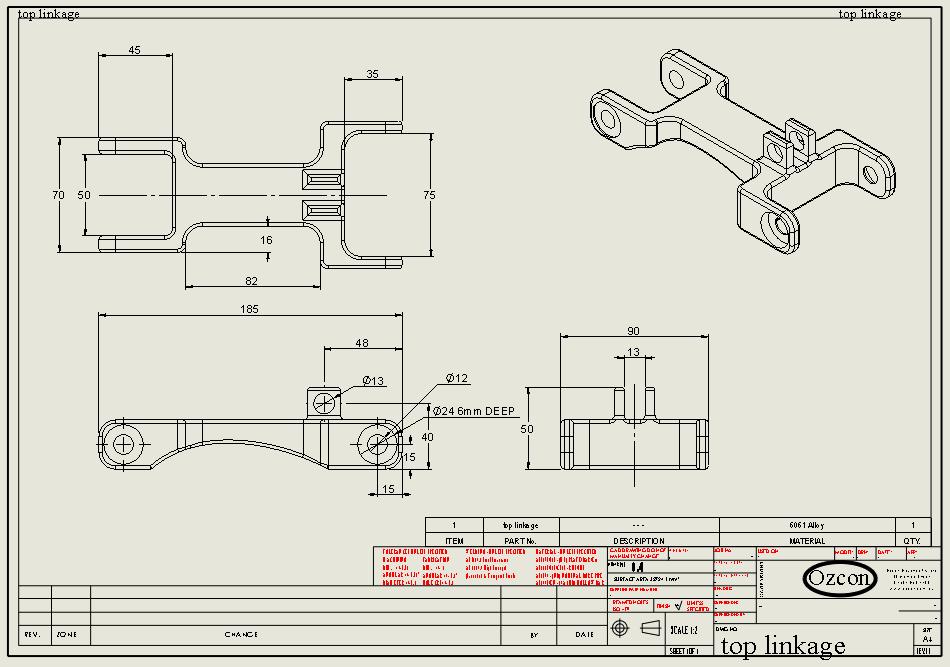
88 78
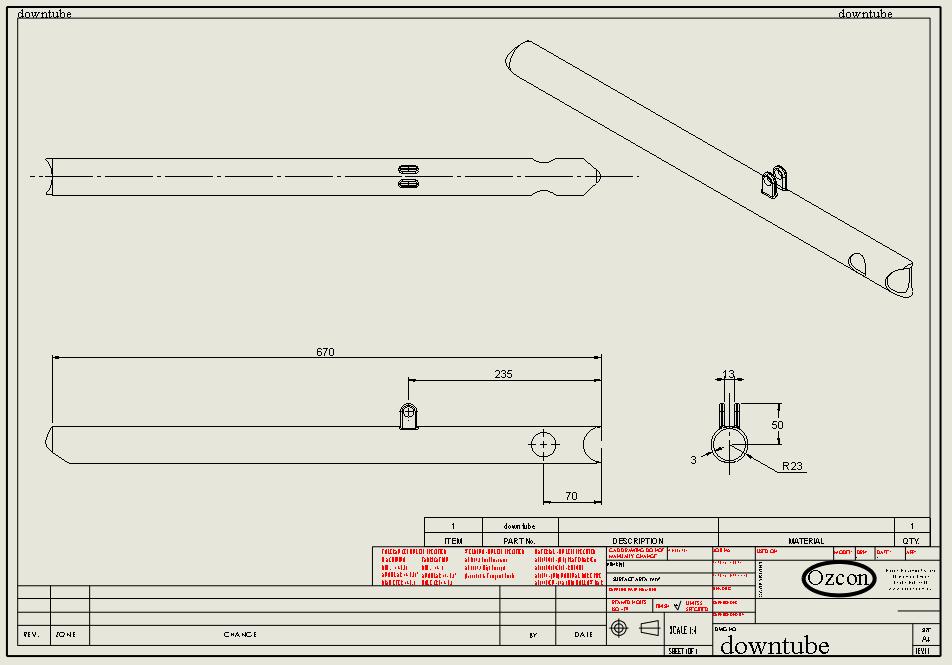
89 79
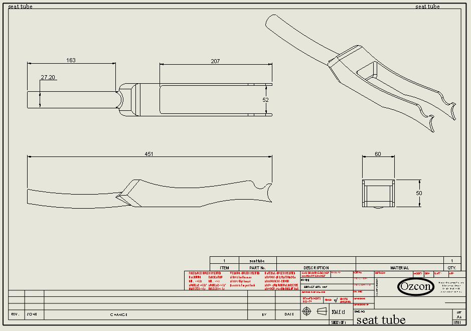
90 80
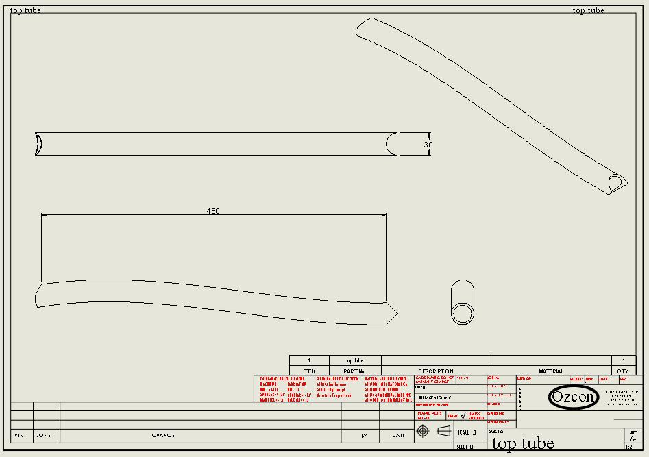
91 81
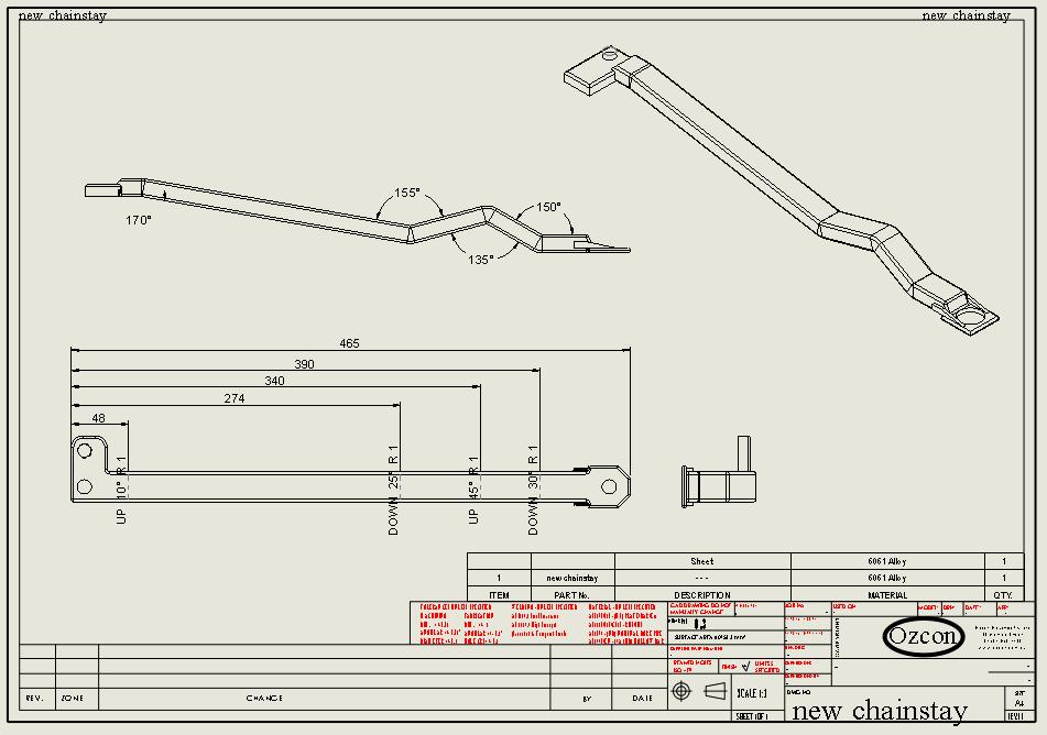
92 82
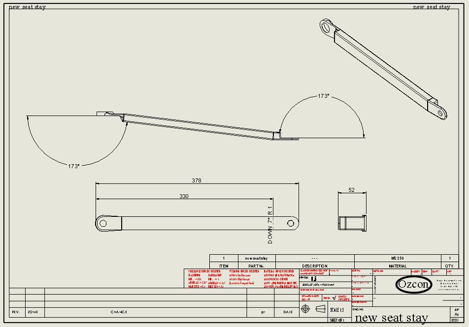
93 83
94 Appendix C: Material Selection Charts 84
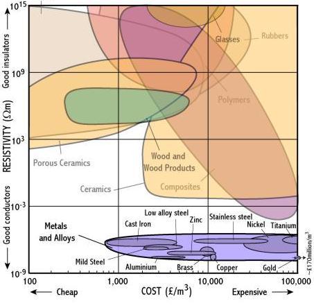
95 85
SCOTT SPORTS SA _17 RTE DU CROCHET_1762 GIVISIEZ_SWITZERLAND _ 2009 SCOTT SPORTS SA, ALL RIGHTS RESERVED_SCOTT-SPORTS.
 SCOTT SPORTS SA _17 RTE DU CROCHET_1762 GIVISIEZ_SWITZERLAND _ 2009 SCOTT SPORTS SA, ALL RIGHTS RESERVED_SCOTT-SPORTS.COM V GAMBLER CONTENT The Gambler should be adjusted exactly to the current rider for
DECREE TECH FEATURES FELT LONG, LOW, SLACK GEOMETRY
 TECH FEATURES FELT DECREE In October 2015, Felt Bicycles introduced an entirely new trail bike into its family: the Decree. Through many iterations of development and design, plus demanding testing and
From Constraints to Components at Marin Bicycles
 From Constraints to Components at Marin Bicycles A Case Study for The Mechanical Design Process Introduction This case study details the development of the Marin Mount Vision Pro mountain bicycle rear
scott 2012 bike owners manual SCOTT SPORTS SA 17 RTE DU CROCHET 1762 GIVISIEZ SWITZERLAND 2011 SCOTT SPORTS SA, ALL RIGHTS RESERVED SCOTT-SPORTS.
 scott 2012 bike owners manual VoltaGE FR F SCOTT SPORTS SA 17 RTE DU CROCHET 1762 GIVISIEZ SWITZERLAND 2011 SCOTT SPORTS SA, ALL RIGHTS RESERVED SCOTT-SPORTS.COM content Voltage FR Concept...P. 004 Geometry
GAMBLER SCOTT 2011 BIKE OWNERS MANUAL
 SCOTT 2011 BIKE OWNERS MANUAL D SCOTT SPORTS SA 17 RTE DU CROCHET 1762 GIVISIEZ SWITZERLAND 2009 SCOTT SPORTS SA, ALL RIGHTS RESERVED SCOTT-SPORTS.COM CONTENT Gambler Concept P. 004 Geometry/Technical
03 Xtension Xplore Fact Sheet
 03 Xtension Xplore Fact Sheet 1. About the Xplore Bike! Development began in 1999! Goal was to develop a bike that " Offered 5 ~6 long travel for Freeride/Allround riding " Fully active under pedaling
IGNITE ALLOY 29. frame passport
 IGNITE ALLOY 29 frame passport last update: 18/01/2016 INDEX 0. UPDATES... 3 1. GENERAL... 3 1.1. Description... 3 1.2. Part codes... 3 2. MATERIAL... 3 3. WEIGHT... 3 3.1. Frame... 3 4. GEOMETRY... 3
scott 2012 bike owners manual SCOTT SPORTS SA 17 RTE DU CROCHET 1762 GIVISIEZ SWITZERLAND 2011 SCOTT SPORTS SA, ALL RIGHTS RESERVED SCOTT-SPORTS.
 scott 2012 bike owners manual D SCOTT SPORTS SA 17 RTE DU CROCHET 1762 GIVISIEZ SWITZERLAND 2011 SCOTT SPORTS SA, ALL RIGHTS RESERVED SCOTT-SPORTS.COM content Gambler Concept...P. 004 Geometry/Technical
FREQUENTLY ASKED QUESTIONS ANSWERED! MOUNTING TO MY BIKE
 FREQUENTLY ASKED QUESTIONS ANSWERED! MOUNTING TO MY BIKE Will a Rohloff hub work on my bike? It is likely that the Rohloff hub will work on your bike as there are number of different hub configurations,
DISCOVER NEW OPTIONS THE NEW GENERATION X
 DISCOVER NEW OPTIONS THE NEW GENERATION X MULTIFUNCTIONAL ALL MOUNTAIN FRAME CONCEPT 3 VERSIONS: CARBON ALUMINIUM EMTB 3 WHEEL SIZES WITH TYRE WIDTH UP TO 3.00 IN 1 FRAME: TRAIL: 27.5 WHEELS TRACTION:
SCOTT SCOTT-SPORTS.COM SAG-BOY BIKE OWNERS MANUAL GAMBLER OWNERS MANUAL / BEDIENUNGSANLEITUNG / MANUEL D UTILISATION
 SCOTT-SPORTS.COM GAMBLER SAG-BOY The lengths of the grey beam shows the optimum eye-to-eye distance of the rear shock. Der graue Balken zeigt den optimalen Bolzenabstand des Dämpfers. La longueur de la
IGNITE CARBON 29. frame passport
 IGNITE CARBON 29 frame passport last update: 11/10/2017 INDEX 0. UPDATES... 3 1. GENERAL... 3 1.1. Description... 3 1.2. Part codes... 3 2. MATERIAL... 3 3. WEIGHT... 3 3.1. Frame... 3 4. GEOMETRY... 4
DESIGN BEHIND THE BIKE WHEELS
 DESIGN BEHIND THE BIKE WHEELS INTRODUCTION Far from being a simple, round, spinning object, the component parts of a wheel combine to affect weight, aerodynamics and the overall performance of a bike.
SCOTT GAMBLER BIKE OWNER S MANUAL
 www.scott-sports.com SCOTT GAMBLER All rights reserved 2014 SCOTT Sports SA SCOTT Sports SA 17 Route du Crochet 1762 Givisiez Switzerland BIKE OWNER S MANUAL 2015 Distribution: SSG (Europe) Distribution
owner s manual 2012 yeti arc
 owner s manual 2012 yeti arc YETI CYCLES 600 Corporate Circle, Unit D Golden, CO 80401 888.576.9384 www.yeticycles.com Table of Contents Brand Overview 06 Frame Features 08 Geometery 10 Maintenance Schedule
GAMBLER SCOTT 2013 BIKE OWNERS MANUAL
 SCOTT 2013 BIKE OWNERS MANUAL SCOTT SPORTS SA 17 RTE DU CROCHET 1762 GIVISIEZ SWITZERLAND 2011 SCOTT SPORTS SA, ALL RIGHTS RESERVED SCOTT-SPORTS.COM D CONTENT Gambler Concept...P. 004 Geometry/Technical
Finite Element Analysis of an Aluminium Bike Frame
 Finite Element Analysis of an Aluminium Bike Frame Word Count: 1484 1 1. Introduction Each new bike model must pass a series of structural tests before being released for public retail. The purpose of
SCOTT VOLTAGE FR USER MANUAL
 SCOTT VOLTAGE FR USER MANUAL All rights reserved 2017 SCOTT Sports SA Distribution: SSG (Europe) Distribution Center SA, P.E.D. Zone C1, Rue du Kiell 60, 6790 Aubange, Belgium v6.3/040717 WWW.SCOTT-SPORTS.COM
INTRODUCTION TABLE OF CONTENTS 1. ENGLISH INTRODUCTION...PAGE 1 GEOMETRY / FRAME SPECIFICATIONS...PAGE 2-3 FRAME FEATURES...
 TABLE OF CONTENTS INTRODUCTION...PAGE GEOMETRY / FRAME SPECIFICATIONS...PAGE - FRAME FEATURES...PAGE -5 SEAT POST SET-UP...PAGE -5 FRAME HARDWARE KITS...PAGE 6-9 REPLACEABLE DERAILLEUR HANGER...PAGE 0-
«SAG-BOY» BIKE OWNERS MANUAL OWNERS MANUAL BEDIENUNGSANLEITUNG MANUEL D UTILISATION
 «SAG-BOY» OWNERS MANUAL BEDIENUNGSANLEITUNG MANUEL D UTILISATION The length of the grey beam shows the optimum eye-to-eye distance of the rear shocks. Der graue Balken zeigt den optimalen Bolzenabstand
TECHNICAL SUPPORT DOCUMENT FULL SUSPENSION MODELS C7 C9 WARRANTY SMALL PARTS FRAME SPEC/SERVICING
 2016-2018 FULL SUSPENSION MODELS C7 C9 WARRANTY SMALL PARTS FRAME SPEC/SERVICING 2016-2018 FULL SUSPENSION MODELS C7 C9 PG.i WARRANTY INFORMATION COMPLETE BIKES ONE YEAR LIMITED WARRANTY NORCO Bicycles
LYNX "& 29" For the most intrepid riders DIRECT. Extra Stability. New pods that allow using tyres up to 2.4
 LYNX 6 & 29" For the most intrepid riders 430 mm 142 x 12 Extra Stability The Lynx 27.5 «trail» is such that the sensation of safety and control in any descent, however demanding it is, is much higher
TECHNICAL SUPPORT DOCUMENT 2018 CARBON MODELS 650B / 29 WARRANTY SMALL PARTS FRAME SPEC/SERVICING
 2018 CARBON MODELS 650B / 29 WARRANTY SMALL PARTS FRAME SPEC/SERVICING 2018 CARBON MODELS 650B / 29 PG.i WARRANTY INFORMATION OWNERSHIP REGISTER YOUR BIKE The original owner must register his / her new
76 Bicycle MD FRAME KIT for Bafang 1000W
 Qulbix - Preserje 40d, 1352 Preserje Slovenia Europe Phone: 00 386 81 61120 - Email: info@qulbix.com 76 Bicycle MD FRAME KIT for Bafang 1000W Brand: Qulbix Availability: Out Of Stock Price: 671.00 Ex Tax:
SCALP - MEGA - SNAP - FRAME MANUAL
 SCALP - MEGA - SNAP - FRAME MANUAL WARRANTY Nukeproof warrants each new Nukeproof bicycle frame against defects in workmanship and materials for 2 years from the purchase date of the original owner. THIS
Design of a double quadruped for the Tech United soccer robot
 Design of a double quadruped for the Tech United soccer robot M.J. Naber (0571509) DCT report number: 2009.134 Master Open Space project Eindhoven, 21 December 2009 Supervisor dr.ir. P.C.J.N. Rosielle
EZee Glider Manual. Tools needed for Assembly: Wrench (included) Philips Screwdriver (not included) Assembly Instructions
 Philips Screwdriver (not included) Assembly Instructions") EZee Glider Manual Congratulations on your purchase of the EZee Glider! Your glider is designed for years of nearly carefree use by your child. These instructions include how to set up your glider and
EZee Glider Manual Congratulations on your purchase of the EZee Glider! Your glider is designed for years of nearly carefree use by your child. These instructions include how to set up your glider and
OWNER S MANUAL 2013 ARC CARBON
 OWNER S MANUAL 2013 ARC CARBON YETI CYCLES 621 Corporate Circle, Unit B Golden, CO 80401 888.576.9384 www.yeticycles.com TABLE OF CONTENTS BRAND OVERVIEW 01 FRAME FEATURES 04 GEOMETERY 08 MAINTENANCE SCHEDULE
HIGH OCTANE FR & DH OWNERS MANUAL
 HIGH OCTANE FR & DH OWNERS MANUAL The Scott High Octane should be adjusted exactly to the current rider for reaching maximum safety and fun while riding. All adjustments should be done at the local dealer
Build Specs: Shock Specs: eye-to-eye x 2.25" stroke, Upper Pin 46mm x 8mm, Lower Pin 22.2mm x 8mm Website 2006 Bikes
 2007 Website 2006 Bikes Overview Pricing/Components Sizing/Geometry Larger View As the evolution of freeriding continues to get crazier, the DirtBag was designed to meet rider's needs taking it to the
SCALE CARBON SCOTT 2011 BIKE OWNERS MANUAL
 SCOTT 2011 BIKE OWNERS MANUAL H SCOTT SPORTS SA 17 RTE DU CROCHET 1762 GIVISIEZ SWITZERLAND 2009 SCOTT SPORTS SA, ALL RIGHTS RESERVED SCOTT-SPORTS.COM CONTENT Scale Carbon Concept P. 004 Geometry Scale
TECHNICAL SUPPORT DOCUMENT 2018 CARBON MODELS 650B / 29 WARRANTY SMALL PARTS FRAME SPEC/SERVICING
 2018 CARBON MODELS 650B / 29 WARRANTY SMALL PARTS FRAME SPEC/SERVICING 2018 CARBON MODELS 650B / 29 PG.i NORCO BICYCLES NEW PURCHASE CONSUMER WARRANTY PROGRAM - EFFECTIVE ON ALL 2017 MODEL YEAR BICYCLES
a bike with a history like no other
 a bike with a history like no other First introduced in 201, the Nitrogen set itself apart from other Aero bikes by its versatility, its impeccable handling and stiffness. The Nirogen Pro followed in 2016
SCALE CARBON SCOTT 2013 BIKE OWNERS MANUAL
 SCALE CARBON SCOTT 2013 BIKE OWNERS MANUAL SCOTT SPORTS SA 17 RTE DU CROCHET 1762 GIVISIEZ SWITZERLAND 2011 SCOTT SPORTS SA, ALL RIGHTS RESERVED SCOTT-SPORTS.COM H content Scale Carbon Concept... P. 004
Double butted 3/2.5 titanium tube set
 2009 Titanium with Argyle Panels December 2008 1 2 3 4 5 6 7 8 9 10 11 12 13 14 15 16 17 18 19 20 21 22 23 24 25 26 27 28 29 30 31 Our classic cross country hardtail with state of the art tubing and construction.
Spot Rollik 607 Suspension Setup Guide Table of Contents
 Spot Rollik 607 Suspension Setup Guide Table of Contents Warning Intended Use A. Rear Shock Pressure/Sag Setting B. Rear Shock Rebound Setting C. Rear Shock Compression Adjustment D. Rear Shock Volume
HIGH OCTANE FR & DH OWNERS MANUAL 0-1. Content
 Manual A5high oct 04_E 30.09.2003 14:22 Uhr Seite 2 The Scott High Octane should be adjusted exactly to the current rider for reaching maximum safety and fun while riding. All adjustments should be done
Mini Glider Manual. Your Glider comes partially assembled. The front wheel and the handlebars require assembly.
 Mini Glider Manual Congratulations on your purchase of the Mini Glider! Your glider is designed for years of nearly carefree use by your child. These instructions include how to set up your glider and
comfort without compromising on performance and to fit your various needs on touring,
 Congratulations on your purchase of Goal-26X. Goal-26X is made to enhance comfort without compromising on performance and to fit your various needs on touring, shopping and communicating. Let s have fun
OTSO VOYTEK. Otso Cycles is a new bicycle company from the engineers. Designed to excel in any condition BIKE TEST / OTSO VOYTEK
 BIKE TEST / Designed to excel in any condition Otso Cycles is a new bicycle company from the engineers at Wolf Tooth Components. One might ask where they got this unique name, and the founders are happy
TB Title: Mountain Bike Maintenance Part 1 of 2
 Technical Brief No.: TB-09-0528 Title: Mountain Bike Maintenance Part 1 of 2 For many New England mountain bikers and other cyclist, spring is that time of the year to make sure your bike is safe and ready
Parts List. 7. Handlebars 8. Grips 9. Handlebar Stem 10. Front Brake 11. Front Wheel 12. Crank 13. Chain
 Woodworm Cruise Parts List 1. Free Wheel with Rear Hub 2. Fenders 3. Fender Stay 4. Quick Release 5. Saddle 6. Seat Post 7. Handlebars 8. Grips 9. Handlebar Stem 10. Front Brake 11. Front Wheel 12. Crank
Quattrocycle BV. Quattrocycle. User Manual. Last update February Quattrocycle BV Bremkant EJ Middelbeers. User Manual Quattrocycle 1
 Quattrocycle User Manual Last update February 2010 Quattrocycle BV Bremkant 6 5091 EJ Middelbeers User Manual Quattrocycle 1 Table of Contents Page Chapter 1: Introduction 3 Chapter 2: Instructions for
Special instruction of installation for SAINT FH-M800/RD-M800 and FH-M805/RD-M805
 Technical Service Instructions SI-5VB0E t RD-M805 / RD-M800 Rear derailleur Special instruction of installation for SAINT FH-M800/RD-M800 and FH-M805/RD-M805 A hub axle is an essential component for the
MARIN BIKES 2009 NEW SERIES OVERVIEW
 CONTACT: Mark Vanek 800-222-7557 Ext 117 mark@marinbikes.com MARIN BIKES 2009 NEW SERIES OVERVIEW 1. MARIN QUAD LINK SUSPENSION BREAKDOWN 2. QUAD XCR FULL SUSPENSION 3. QUAD XC FULL SUSPENSION 4. QUAD
Manual A5high oct 04_E :50 Uhr Seite 2 CONTENT
 Manual A5high oct 04_E 17..2004 13:50 Uhr Seite 2 CONTENT > Concept High Octane p. 2 > Characteristics p. 2 > Adjustable head angle p. 3-4 > Adjustable seat angle p. 4 > Adjustable saddle height p. 5 >
BIKE CHAIN BASICS. Figure 1 - Two different sizes of bicycle chain
 BIKE CHAIN BASICS Figure 1 - Two different sizes of bicycle chain When creating your own human powered vehicles, a chain drive will likely be your chosen power transfer system, as it is an inexpensive,
NINER. RKT 9 RDO Big wheels and big ambitions Niner has created a community of cyclists who are BIKE TEST / NINER RKT 9 RDO. 46
 NINER RKT 9 RDO Big wheels and big ambitions Niner has created a community of cyclists who are fiercely loyal to its brand and for good reason. They have grown from a niche company into a strong contender
CRUZBIKE Quest 2.0 Assembly
 CRUZBIKE Quest 2.0 Assembly CRUZBIKE Quest 2.0 Assembly... 1 General notes on assembly... 2 Un box and evaluate the frame and major parts... 2 Unfold the rear swing arm and arrange the frame... 3 Rear
WE'LL TAKE YOU THERE SHINING THROUGH THE YEARS WITH IRMIGERRR AND JHK FROM A TO BO RIDING THE ARCTIC CIRCLE
 WE'LL TAKE YOU THERE number 38 $8.95 US $9.95 CAN www.mountainflyer.com 0 7 4 4 7 0 2 4 7 6 1 6 Display until November 3, 2014 0 5 SHINING THROUGH THE YEARS WITH IRMIGERRR AND JHK FROM A TO BO RIDING THE
HPA Power Transmission. Everardo Uribe
 HPA Power Transmission There are several forces the HPA has to overcome, most of these forces will have to be overcome by the power transmission component. The main force will of course be aerodynamic
helium SLA frame passport
 helium SLA frame passport type: 7E2 last update: 25/09/2017 INDEX 0. UPDATES... 3 1. GENERAL... 3 1.1. Description... 3 1.2. Part codes... 3 2. MATERIAL... 3 3. WEIGHT... 3 3.1. Frame... 3 3.2. Fork...
moto Owner s Manual Supplement PDF CONTENTS
 READ THIS SUPPLEMENT AND YOUR CANNONDALE BICYCLE OWNER S MANUAL CAREFULLY! Both contain important safety information. Keep both for future reference. moto Owner s Manual Supplement 122172.PDF CONTENTS
Ladies Shopper Bike Assembly Manual 28C03
 Ladies Shopper Bike Assembly Manual 28C03 Ecosmo Ltd 1 Know your bike 1. Wheel 2. Rear Derailleur 3. Chain 4. Crank Set 5. Pedal 6. Seat Quick Lock 7. Saddle and Post 8. Frame 9. Front Light 10. Front
600 Corporate Circle, Unit D Golden, CO USA P// //
 Yeti Cycles 600 Corporate Circle, Unit D Golden, CO USA P//303.278.6909 // 888.576.9384 www.yeticycles.com A R C - X O W N E R S M A N U A L 0 8-1 0 Table of Contents Brand Overview 6 Frame Features 8
SUPERIOR TEAM/XP CRB BF-M03 SERVICE MANUAL
 SUPERIOR TEAM/XP CRB BF-M03 SERVICE MANUAL Superior would like to congratulate you on the purchase of your new bicycle. We place a great emphasis on the choice of materials and their processing so as to
Congratulations on your purchase of a JC Series Performer trike! The Performer JC Series is designed for everything from touring to commuting and
 Congratulations on your purchase of a JC Series Performer trike! The Performer JC Series is designed for everything from touring to commuting and shopping in the city. The JC Series frames are made of
Millennial Walker A multi-functional, elderly assistance walker with improved posture, comfort, and folding capabilities.
 Millennial Walker A multi-functional, elderly assistance walker with improved posture, comfort, and folding capabilities. Background & Research Question There are many different styles and categories when
MOUNTAIN CYCLE. ROCKET SCIENCE FOR THE REAL WORLD.
 MOUNTAIN CYCLE PRODUCT GUIDE 2004 Our engineers built the first Mountain Cycle monocoque frame in 1989. The latest frame was welded at our headquarters in Portland, Oregon, a couple days ago. Between then
SCOTT PLASMA 4 BIKE OWNER S MANUAL
 www.scott-sports.com SCOTT PLASMA 4 All rights reserved 2014 SCOTT Sports SA SCOTT Sports SA 17 Route du Crochet 1762 Givisiez Switzerland BIKE OWNER S MANUAL 2015 Distribution: SSG (Europe) Distribution
Trilogy Theory of Operation
 INSTALLATION & OVERVIEW... 2 Load Height... 2 Approach Angle... 2 Footprint... 3 Protrusion... 3 Mounting the... 4 General Torque Specs... 4 OPERATION OF BIKE RACK... 5 Loading Bikes... 5 Unloading Bikes...
WHITE PAPER Copyright Cicli Pinarello SRL - C.F. e P.I
 WHITE PAPER 2017 - Copyright Cicli Pinarello SRL - C.F. e P.I. 05994100963 INDEX 0. INTRODUCTION... 3 1. PINARELLO NYTRO BIKE CONCEPT... a. PURPOSES OF THE PROJECT... b. HANDLING AND RIDING FEELING...
P DH RA ARK CE/ DH RACE/ PARK
 DH RACE/ PARK 2014 DH RACE/ PARK Bike Series: AURUM Whether you re into World Cup downhill runs, endless park days or after-work shuttle laps, the Aurum delivers unbelievable performance in any gravity-oriented
BLUE PAPERS AVANT OMP TECHNICAL MANUAL
 BLUE PAPERS AVANT OMP TECHNICAL MANUAL AVANT OMP TECHNICAL SPECIFICATIONS 1 CONTENT GEOMETRY 3 ERGONOMY 4 SPECIFICATIONS 5 FRAME AND MATERIAL 6 PARTS & HARDWARE 7 CABLE ROUTING 11 TORQUE SPECIFICATIONS
OWNER'S MANUAL ENG. skyline 3.0
 OWNER'S MANUAL ENG skyline 3.0 eng Thank you for choosing a DEDAcciai product. We in DEDAcciai develop, manufacture, and constantly test our products in order to maintain the highest standards of quality.
Have questions? Chat with us live at raleighusa.com or call us at , 8am 5pm PST
 1 2 Have questions? Chat with us live at raleighusa.com or call us at 1-800-251-8435, 8am 5pm PST The bicycle you have purchased is a complex piece of equipment that must be properly assembled and maintained
Model year 2014 USER MANUAL
 Model year 2014 USER MANUAL WARRANTY Terms and conditions BOS MTB offers warranty on its products on the following terms : BOS MTB guarantees to the original purchaser that the BOS product for which they
Niner JET 9 RDO Review
 29er Online 29 Inch Mountain Bike Reviews Home Shop About Community Guidlines Advertise Testers Contact Us Niner JET 9 RDO Review by FatBob on January 10, 2013 The 2012 Niner JET9 carbon, the bike formerly
INSTRUCTION GUIDE TRANSITION CARBON (ALL MODELS)
") INSTRUCTION GUIDE TRANSITION CARBON (ALL MODELS) THIS INSTRUCTION GUIDE CONTAINS IMPORTANT INFORMATION. PLEASE READ CAREFULLY AND STORE IN A SAFE PLACE. Congratulations! The Specialized bicycle you have
INSTRUCTION GUIDE TRANSITION CARBON (ALL MODELS) THIS INSTRUCTION GUIDE CONTAINS IMPORTANT INFORMATION. PLEASE READ CAREFULLY AND STORE IN A SAFE PLACE. Congratulations! The Specialized bicycle you have
Edict Suspension Manual
 Contents:.. 5. 7. Introduction FAST Function Simply Explained Setup Rebuild/Maintenance Parts Lists Carbon Care Guide Warranty. Introduction: Congratulations on purchasing this high quality Felt bicycle.
Tis a new season again, and coming right along in this new era of mountain bikes, Foes is strapped for the challenge.
 Tis a new season again, and coming right along in this new era of mountain bikes, Foes is strapped for the challenge. Now in its 11th year of bicycle manufacturing Foes Racing has redefined bicycling as
Course outlineimportant: As personnel i
 Bike SA Inc Advanced Bike Maintenence Course Course outlineimportant: As personnel i nvolved in this program it is your responsibility to familiarise yourself with this document Please familiarise yourself
DM-MBRD (English) Dealer's Manual. ROAD MTB Trekking. City Touring/ Comfort Bike. Rear Derailleur SLX RD-M7000 DEORE RD-M6000
 Dealer's Manual. ROAD MTB Trekking. City Touring/ Comfort Bike. Rear Derailleur SLX RD-M7000 DEORE RD-M6000") (English) DM-MBRD001-04 Dealer's Manual ROAD MTB Trekking City Touring/ Comfort Bike URBAN SPORT E-BIKE Rear Derailleur SLX RD-M7000 DEORE RD-M6000 CONTENTS IMPORTANT NOTICE... 3 TO ENSURE SAFETY... 4
(English) DM-MBRD001-04 Dealer's Manual ROAD MTB Trekking City Touring/ Comfort Bike URBAN SPORT E-BIKE Rear Derailleur SLX RD-M7000 DEORE RD-M6000 CONTENTS IMPORTANT NOTICE... 3 TO ENSURE SAFETY... 4
By: Enduro Mountain Bike Magazine Published: August 3, 2015
 First Ride: Cannondale Habit Trailbike By: Enduro Mountain Bike Magazine Published: August 3, 2015 It has been a long wait but worth every second; last week the crew from Cannondale presented the Habit,
X-TRAIL ALLOY. frame passport
 X-TRAIL ALLOY frame passport Type: 7DF last update: 18/10/2016 INDEX 0. UPDATES... 3 1. GENERAL... 3 1.1. Description... 3 1.2. Part codes... 3 2. MATERIAL... 3 3. WEIGHT... 3 3.1. Frame... 3 3.2. Fork...
Cables & Housing (and hose) THE FRAME & FORK DICTATE THE BRAKE STYLE
 THE FRAME & FORK DICTATE THE BRAKE STYLE") Most riders are at least familiar with brakes, because brakes require frequent adjustment for proper function and safety. There are some features common to all brakes, but there are also many unique styles.
Most riders are at least familiar with brakes, because brakes require frequent adjustment for proper function and safety. There are some features common to all brakes, but there are also many unique styles.
Camberley U3A Science & Technology. Modern bicycle technology
 Camberley U3A Science & Technology Modern bicycle technology 1 Overview Why cycle? Bikes - many different types and functions Comfort, weight and aerodynamics Frames and forks; structure, components and
Using Your Bike Friday : Folding Rear Rack
 Using Your Bike Friday : Folding Rear Rack Green Gear Cycling, Inc. 3364 W. 11th Ave. Eugene, OR 97402 800-777-0258 USA & Canada +1-541-687-0487 Int l +1-541-687-0403 Fax www.bikefriday.com info@bikefriday.com
Folding Dual Suspension MTB. Instruction Manual
 Folding Dual Suspension MTB Instruction Manual Introduction The Stowabike Folding MTB has been made to last and with proper maintenance, it will give you years of enjoyable rides and journeys. The following
SUSPENSION 1 FAST: EQUILINK:
 Felt designs its suspension and frame platforms together with the single objective of delivering the best possible ride for any conditions or ride experiences. With this approach, Felt engineers are able
QUIVER KILLER: NEW COLOR, NEW CARBON THE RDO CARBON COMPACTION SYSTEM DEBUTS IN NINER S FLAGSHIP TRAIL BIKE PLATFORM
 : NEW COLOR, NEW CARBON THE RDO CARBON COMPACTION SY DEBUTS IN NINER S FLAGSHIP TRAIL BIKE PLATFORM KEY FEATURES RDO CARBON LAYUP FOR NO-COMPROMISE STIFFNESS, STRENGTH AND RIDE QUALITY 125MM OF PATENTED
COMPRESSED AIR DISTRIBUTION SYSTEMS
 Series COMPRESSED AIR DISTRIBUTION SYSTEMS 18 DESIGNING AN EFFICIENT COMPRESSED AIR DISTRIBUTION The main source of inefficiencies and problems affecting compressed air distribution systems is often the
Top End Recreation Handcycle Series
 Top End Recreation Handcycle Series Top End Excelerator Handcycle If you want a great way to exercise, cross-train or just have fun, the Top End Excelerator handcycle is what you need. This upright and
9-speed super narrow. chain such as. CN-7701 / CN-HG93 8- / 7- / 6-speed narrow. chain such as CN-HG50 / CN-IG51
 - Technical Service Instructions SI-5VH0B t RD-M600 Rear derailleur General Safety Information WARNING The ST-M600 DUAL CONTROL lever is used for both gear shifting and braking operations. Make sure that
DM-MARD (English) Dealer's Manual. ROAD MTB Trekking. City Touring/ Comfort Bike REAR DERAILLEUR XTR RD-M9100 RD-M9120
 Dealer's Manual. ROAD MTB Trekking. City Touring/ Comfort Bike REAR DERAILLEUR XTR RD-M9100 RD-M9120") (English) DM-MARD001-00 Dealer's Manual ROAD MTB Trekking City Touring/ Comfort Bike URBAN SPORT E-BIKE REAR DERAILLEUR XTR RD-M9100 RD-M9120 CONTENTS CONTENTS...2 IMPORTANT NOTICE...3 TO ENSURE SAFETY...4
(English) DM-MARD001-00 Dealer's Manual ROAD MTB Trekking City Touring/ Comfort Bike URBAN SPORT E-BIKE REAR DERAILLEUR XTR RD-M9100 RD-M9120 CONTENTS CONTENTS...2 IMPORTANT NOTICE...3 TO ENSURE SAFETY...4
FRAMES, SUSPENSION, FORKS AND SHOCKS
 FRAMES, SUSPENSION, FORKS AND SHOCKS FRAMES.5 Frame, Suspension and Handling Cradle Frame Backbone Frame Diamond Frame Twin-Spar Frame Trellis Frame Frame Electrical Grounds FRONT SUSPENSION...12 Telescopic
The Time Has Come For Coiled Rod. Reprinted from Well Servicing magazine
 The Time Has Come For Coiled Rod Reprinted from Well Servicing magazine The development of flush-by well service units and stand-alone coiled rod injector head technology has helped grow the coiled rod
Mayhem and Living Link Frames Assembly Instructions and Suspension Setup Manual
 Mayhem and Living Link Frames Assembly Instructions and Suspension Setup Manual Table of Contents Warning Intended Use Frame Geometry Component Compatibility Frame Assembly Section Tools Required A. Internally
2003 CRF450R PRESS INFORMATION
 2003 CRF450R PRESS INFORMATION Cleared for take-off by the FIM in 2003, and primed to grab big air on motocross and supercross circuits the length and breadth of Europe, Honda s spectacular CRF450R has
SPOKES & NIPPLES FOR BICYCLE 2017
 SPOKES & NIPPLES FOR BICYCLE 2017 HISTORY AND PRESENT Based in Lomagna, in the heart of Lombardy, Alpina Raggi S.p.A. was founded in 1926 and focusses its activity on the production of spokes and nipples.
Quickie Rigid Series QUICKIE RIGID STYLE DURABILITY INNOVATION TECHNOLOGY ADJUSTABILITY OPTIONS LIFESTYLE
 Quickie Rigid Series STYLE DURABILITY INNOVATION TECHNOLOGY ADJUSTABILITY OPTIONS LIFESTYLE QUICKIE RIGID Ti Titanium Quickie T he Quickie Ti Titanium, the chair that expresses the essence of Quickie quick
EZ-3 USX HD Supplemental Owner s Manual
 EZ-3 USX HD Supplemental Owner s Manual Find us online at SunSeeker.Bike Revised 2/2016 CONGRATULATIONS! Congratulations and welcome to the Sun Seeker family! You have selected one of the most comfortable
RADON 237A: ASSEMBLY GUIDE. Revision Valid for MY2017 Radon
 RADON 237A: ASSEMBLY GUIDE Revision 3.0-05-29-2017 - Valid for MY2017 Radon RADON 237A: Table of Contents 1. Tools Needed and First Aid Kit... 3 2. Sizing Chart... 4 3. Seat Post Collar Assembly... 5 4.
Final Assembly Instructions Bikes with Quill Stems
 Final Assembly Instructions Bikes with Quill Stems Thank you for buying your new bicycle from L.L.Bean. Read these instructions carefully before beginning the final assembly. Prior to shipping, our expert
X-TRAIL ALLOY 650B. frame passport
 X-TRAIL ALLOY 650B frame passport Type: 7E1 last update: 13/09/2017 INDEX 0. UPDATES... 3 1. GENERAL... 3 1.1. Description... 3 1.2. Part codes... 3 2. MATERIAL... 3 3. WEIGHT... 3 3.1. Frame... 3 3.2.
NINER BIKES 2010 >> THE NEW JET 9. What makes the next-generation Jet 9 so much stronger and stiffer?
 1 THE NEW JET 9 What makes the next-generation Jet 9 so much stronger and stiffer? The evolution of the Jet 9 began with FEA (computer modeling) and real-world testing completed during the development
SANTA CRUZ BICYCLES Cable Routing Procedure MY17
 SANTA CRUZ BICYCLES Cable Routing Procedure MY17 Copyright Santa Cruz Bicycles 2017 TABLE OF CONTENTS SAFETY INSTRUCTIONS... 3 CABLE ROUTING... 3 INTRODUCTION...3 TOOLS AND SUPPLIES...3 REAR DERAILLEUR
Prime Race Road Alloy Wheelset
 Prime Race Road Alloy Wheelset by Mat Brett September 22 2016 9 Comments Verdict: Lightweight alloy clincher wheelset that's hardwearing and tubeless-ready out of the box Weight: 1,530g Contact: primebikecomponents.com
Sprocket Selection Guidelines
 Sprocket Selection Guidelines Table 1 Information Necessary to Order Sprockets 1. Chain Size Number, type, or drawing number of the chain to be used on the sprocket. (The suitability of a sprocket depends
E-trike Li Assembly Guide
 PREPARATION 1. Read this assembly manual BEFORE commencing assembly. 2. Carefully remove all the components and packaged hardware from the shipping boxes. 3. Unpack the contents of the large double box