FM DEPARTMENT OF THE ARMY FIELD MANUAL
|
|
|
- Antony Byrd
- 6 years ago
- Views:
Transcription
1 FM DEPARTMENT OF THE ARMY FIELD MANUAL ANTIPERSONNEL MINE M18A1 AND M18 (CLAYMORE) This copy is a reprint which includes current pages from Changes 1 and 2. HEADQUARTERS, DEPARTMENT OF THE ARMY JANUARY 1966
2 FM C2 CHANGE HEADQUARTERS DEPARTMENT OF THE ARMY NO.2 WASHINGTON, D.C. 30 March 1973 ANTIPERSONNEL MINE, M18A1 and M18 (CLAYMORE) FM 23-23, 6 January 1966, is changed as follows: Page 2, para 3, line 13. The words (knife-edge sight on later model) is added after slit/type sight,. Page 2, para 3, line 15. The last sentence of paragraph 3 is changed to read: An instruction sheet for the M18A1 mine is attached to the inside cover of the bandoleer. The instruction sheet which accompanies the M18A1 mine having the knife-edge sight is shown in figure 3. TAGO-3366A 1
3 C2, FM Page 3. Figure 1 is superseded. 2


4 Page 6. Figure 3 is superseded. C2, FM
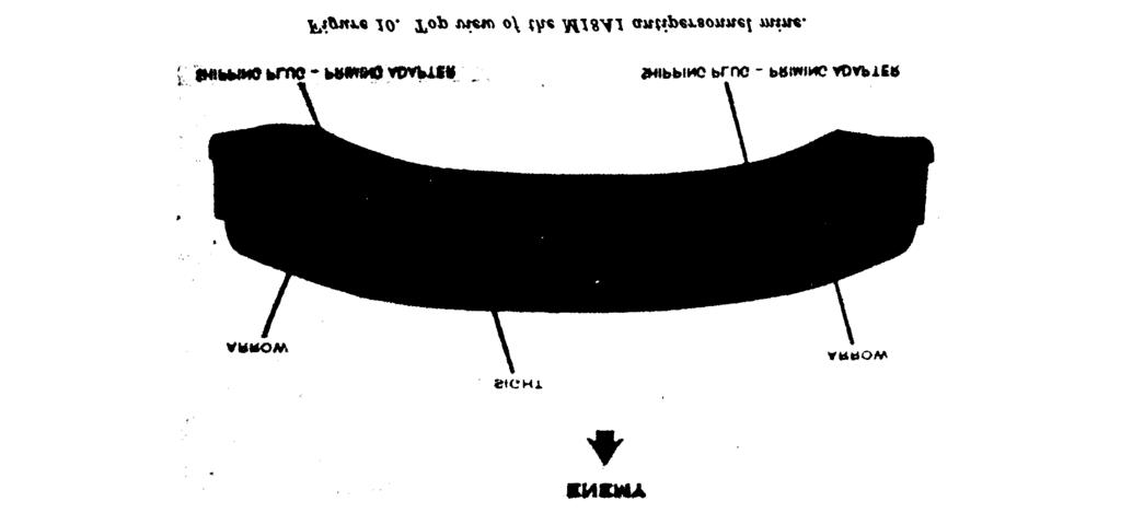
5 C2, FM Page 8, para 7c(9), line 1. The words Peepsight and arrows. are changed to read Sight and arrows. Page 8, para 7a(9), line 2. The words (or knife-edge sight) are added after the word peepsight. Page 9, para 7b(2), line 2. The word assembly is added after the word cap. Page 9, para 7b(2). The following note is added: Note. With mines of later manufacture, the M4 electrical blasting cap assembly is wound on a spool. Page 11, paragraph 12 is superseded as follows: 12. Installation for Electrical Firing a. Laying and Aiming. (1) Laying. (a) Check to see that the mine and all accessories (fig. 2) are in the bandoleer. Read the instruction sheet (fig. 3) attached inside the bandoleer cover before installing the mine. (b) Remove the electrical firing wire leaving the mine and other accessories in the bandoleer. Warning: During installation the M57 firing device must be kept in the possession of the man installing the mine to prevent accidental firing by a second man. (c) Secure the shorting plug end of the firing wire at the firing position. Place the bandoleer on your shoulder and unroll the firing wire to the position selected for emplacing the mine. Note. The instructor sheet which accompanies the M18A1 mine with slit-type peepsight indicates that the firing wire can be unrolled from the mine or from the firing position; however, the firing wire should always be laid from the firing psition to the mine emplacement. (d) Remove the mine from the bandoleer; turn the legs rearward and then downward. Spread each pair of legs about 45 degrees. One leg should protrude to the front and one to the rear of the mine. Position the mine with the surface marked FRONT TOWARD ENEMY and the arrows on top of the mine pointing in the direction of the enemy or the desired area of fire. On snow or extremely soft ground the bandoleer may be spread beneath the mine for support. (e) To prevent tipping in windy areas or when the legs cannot be pressed into the ground, spread the legs to the maximum (about 180 so that the legs are to the front and rear of the mine. A top view of the M18A1 antipersonnel mine is shown in figure 10. (2) Aiming. (a) Mines with slit-type peepsight. 1. Select an aiming point which is about 50 meters (150 feet) to the front of the mine and about 2½ meters (8 feet) above the ground (fig. 11). 2. Position the eye about 15 centimeters (6 inches) to the rear of the sight. Aim the mine by sighting through the peepsight. The groove of the sight should be in line with the aiming point. The aiming point should be in the center of the desired area of coverage, and the bottom edge of the peepsight should be parallel to the ground that is to be covered with the fragment spray. (b) Mines with knife-edge sight. 1. Select an aiming point at ground level that is about 50 meters (150 feet) in front of the mine. 2. Position the eye about 15 centimeters (6 inches) to the rear of the sight. Aim the mine by alining the two edges of the sight with the aiming point (fig. 11.1). b. Arming and Electrical Firing. (1) Secure the firing wire about 1 meter behind the mine so it will not become misalined should the firing wire be disturbed. (2) Test the firing device, test set, and blasting cap assembly as described in paragraph 15. 4
6 C2, FM Warning. Make certain that the combination shorting plug and dust cover is assembled to the connector of the firing wire before proceeding with installation of the mine. (3) Unscrew one of the shipping plug priming adapters from the mine. Slide the slotted end of the shipping plug priming adapter (fig. 12) onto the firing wires of the blasting cap between the crimped connections and the blasting cap. Pull the excess wire through the slotted end of the adapter until the top of the blasting cap is firmly seated in the bottom portion of the shipping plug priming adapter. Screw the adapter with blasting cap into the detonator. Warning. Make certain that the face of the mine marked Front Toward Enemy and the arrows on top of the mine point in the direction of the enemy. (4) Recheck the aim of the mine. Camouflage the mine and, if possible, bury the firing wire to protect it from fire and enemy detection. Make certain you have the bandoleer and other accessories and then move back to the firing position. Warning. The mine firing position should be in a foxhole or covered position at least 16 meters to the rear or the side of the emplaced mine. (5) Before connecting the M57 firing device (fig. 5) to the firing wire, make certain that the safety bail is in the SAFE position and that all friendly troops within 250 meters of the front and sides and 100 meters of the rear of the mine are under cover. Do not connect the firing device to the firing wire until the actual time of firing. (6) To fire the mine, remove the dust cover on the firing device, remove the combination shorting plug and dust cover from the end of the firing wire, and connect the firing device to the firing wire. Fire the mine by positioning the firing device safety bail in the FIRE position and actuating the firing device handle with a firm, quick squeeze. By Order of the Secretary of the Army: Official: VERNE L. BOWERS Major General, United States Army The Adjutant General CREIGHTON W. ABRAMS General, United States Army Chief of Staff Distribution: To be distributed in accordance with DA Form requirements for Antipersonnel Mine, M18, and M18A1. 5
7 FM C 1 CHANGE HEADQUARTERS DEPARTMENT OF THE ARMY No. 1 WASHINGTON, D.C., 17 December 1968 ANTIPERSONNEL MINE M18A1 AND M18 (CLAYMORE) FM 23-23, 6 January 1966, is changed as follows: is approximately 150 feet in front of the mine. Page 12, paragraph 12 a. Subparagraph 12 a (5) is Position the eye approximately 6 inches (15 cm.) added as follows: to the rear of the sight. Aim the mine by alining (5) When using the mine with the knife-edge the two edges of the sight with the aiming point sight, select an aiming point at ground level that (fig. 11.1). Page 13, figure 11.1 is added as follows: Page 33, appendix IV, paragraph 2 b is superseded as follows: b. Graphic training aid (GTA) , Anti- personnel Mine, M18A1 (Claymore) illustrates the mine and its methods of employment. AGO 713A December
8 C 1, FM By Order of the Secretary of the Army: Official: KENNETH G. WICKHAM, Major General, United States Army, The Adjutant General. W. C. WESTMORELAND, General, United States Army, Chief of Staff. Distribution: To be distributed in accordance with DA Form requirements for Antipersonnel Mine, M18 and M18A1 (CLAYMORE). TAGO 713A
9
10 CHAPTER 1 INTRODUCTION Section I. 1. Purpose and Scope a. This manual provides guidance for commanders and instructors presenting instruction and training on the functioning, installation, and employment of the antipersonnel mine, CLAYMORE. b. This manual describes the M18A1 antipersonnel mine, CLAYMORE, its functioning, and installation. It provides a basis for conducting training utilizing the electric firing system issued with the mine. It also gives guidance for tactical employment and safety requirements. An earlier model of the CLAY- MORE antipersonnel mine, the M18, is covered in appendix II. c. The material contained herein is applicable without modification to both nuclear and nonnuclear warfare. d. Users of this manual are encouraged to submit recommended changes or comments to GENERAL improve the publication. Comments should be keyed to the specific page, paragraph, and line of the text in which the change is recommended. Reasons should be provided for each comment to insure understanding and complete evaluation. Comments should be forwarded direct to the Commandant, United States Army Infantry School, Fort Benning, Ga Roles of the Antipersonnel Mine, CLAYMORE The number of ways in which the CLAY- MORE may be employed is limited only by the imagination of the user. The CLAYMORE is used primarily as a defensive weapon, but has its application in the offensive role. It must be emphasized that when the CLAY- MORE is referred to as a weapon, this implies that it is employed in the controlled role. In the uncontrolled role, the CLAYMORE is considered a mine or boobytrap (FM ). Section II. DESCRIPTION 3. General The M18A1 antipersonnel mine was standardized in 1960, and replaced the M18 antipersonnel mine (app. II). Both mines are similar in appearance and functioning. The M18A1 (fig. 1) is a directional, fixed-fragmentation mine. When employed in the controlled role, it is treated as a one-shot weapon. It is primarily designed for use against massed infantry attacks; however, its fragments are also effective against light vehicles. The M18A1 mine is equipped with a fixer plastic slit-type sight, adjustable legs, and two detonator wells. 2 The mine and all its accessories are carried in the M7 bandoleer (fig. 2). The instruction sheet for the M18A1 is shown in figure Casualty Effects When detonated, the M18A1 mine will deliver spherical steel fragments over a 60 fanshaped pattern that is 2 meters high and 50 meters wide at a range of 50 meters (fig. 4). These fragments are moderately effective up to a range of 100 meters and can travel up to 250 meters forward of the mine. The optimum effective range (the range at which the
11 Figure 1. The M18A1 antipersonnel mine (CLAYMORE). 3
12 most desirable balance is achieved between lethality and area coverage) is 50 meters. 5. Danger Area a. Danger From Fragments (fig. 4). The danger area consists of a 180 fan with a radius of 250 meters centered in the direction of aim. b. Danger Area of Backblast and Secondary Missiles (figs. 4 and 24). Within an area of 16 meters to the rear and sides of the mine, backblast can cause injury by concussion (ruptured eardrums) and create a secondary missile hazard. (1) Friendly troops are prohibited to the rear and sides of the mine within a radius of 16 meters. (2) The minimum safe operating distance from the mine is 16 meters. At this distance, and regardless of how the mine is employed, the operator should be in a foxhole, behind cover, or lying prone in a depression. The operator and all friendly troops within 100 meters of the mine must take cover to prevent being injured by flying secondary objects such as sticks, stones, and pebbles. 4
13 5


14 6
15 7
16 CHAPTER 2 MECHANICAL TRAINING 6. General This section describes and illustrates the M18A1 antipersonnel mine and the electric and nonelectric firing systems that can be used to detonate the mine. Section I. INTRODUCTION 7. Detailed Description a. Mine. (1) Nomenclature --Mine, antipersonnel, M18A1. (2) Common name _CLAYMORE. (3) Type Antipersonnel. (4) Weight ½ pounds. (5) Dimensions ½ inches long; 1 3/8 inches wide; 3¼ inches high (legs folded); 6¾ inches high (legs unfolded). (6) Firing unit The outer surface of construction. the mine is a curved, rectangular, olive-drab, molded case of fiberglass-filled polystyrene (plastic). In the front portion of the case is a fragmentation f a c e containing steel spheres embbedded in a plastic matrix. The back portion of the case behind the matrix contains a layer of explosive. (7) Explosive ½ pounds of composition C4. 8 (8) Detonator wells. Two detonator wells are located on the top of the mine which allows for single or dual priming. These wells are sealed by the plug ends of the shipping plug priming-adapters which prevent entry of foreign materials into the detonator wells. The slotted end of the shipping plug priming-adapter is used to hold an electric blasting cap in place when the mine is armed. The shipping plug priming-adapter is merely reversed when the mine is to be armed. (9) Peepsight and arrows. The molded slit-type peepsight and arrows (fig. 10) located on top of the mine are used to aim the mine. (l0) Legs. Two pairs of scissors-type folding legs located on the bottom of the mine enable it to be emplaced on the ground. The mine can also be tied to posts, trees, etc. b. Accessories. (1) M57 firing device. (a) One M57 electrical firing device is issued with each M18A1. This device is a hand-held pulse generator. A squeeze of the handle produces a double (one positive, one negative) 3-volt electric pulse of sufficient energy to fire the electric blasting cap through the 100 feet of firing wire which is issued with the mine. The M57 device is 4 inches long, approximately 1½ inches wide, 3¼ inches high, and weighs three-fourths of a pound. On one end of the firing device is a rubber connecting plug with a dust cover.

17 (b) (c) The M57 firing device is shown in figure 5. The safety bail on the M57 electrical firing device (fig. 6) has two positions. In the upper SAFE position, it acts as a block between the firing handle and the pulse generator. In the lower FIRE position, it is clear of the firing handle and allows the pulse generator to be activated. The M18A1 antipersonnel mine with the M57 firing device connected is shown in figure 7. The M57 electrical firing device and firing wire should not be discarded after initial use. Another electric blasting cap can be attached to the firing wire and the M57 device can be used to fire other devices, such as fougasse bombs and demolition charges, provided no more than 100 feet of firing wire and one M6 blasting cap are used. (2) M4 electric blasting cap. The M4 electric blasting cap (fig. 7) consists of an M6 electric blasting cap attached to 100 feet of firing wire. Attached to the firing wire connection is a combination shorting plug and dust cover. The shorting plug prevents accidental functioning of the blasting cap by static electricity; the dust cover prevents dirt and moisture from enter- ing the connector. The firing wire is wrapped around a flat paper and then rolled to form a package 6 inches long, 4 inches wide, and 2 inches high. A piece of insulating tape is used to hold the package together. (3) M40 test set. The M40 test set (figs. 17 and 18) is an instrument used for checking the continuity of the initiating circuit of the mine. (For further details on the M40 test set, see para 15.) Note. Only one of the six bandoleers in each packing box contains a test set. The bandoleer containing the test set is marked by an identification tag on the carrying strap (fig. 2). c. M7 Bandoleer. The M7 bandoleer (fig. 2) is constructed of water resistant canvas (olivedrab color) and has snap fasteners which secure the flap. The bandoleer has two pockets; one pocket contains the mine and the other contains a firing device, a test set, and an electric blasting cap assembly. A 2-inch wide web strap,.. which is used as a shoulder carrying strap, is sewn to the bag. An instruction sheet is sewn to the inside flap (fig. 3)

18 Section II. COVERAGE AND METHODS OF FIRE 8. Fire Discipline Since the M18A1 mine can be fired only once, fire discipline is of paramount importance. The mine should not be used against single personnel targets; rather, it should be used for its intended purpose massed personnel. When lead elements of an enemy formation approach within 20 to 30 meters of the mine, it should be detonated. If practicable, and to insure fire discipline, actual authority and responsibility for target selection and timely detonation should rest with squad leaders or their superiors. 9. Controlled Frontal Coverage a. For effective coverage of the entire front of a position, mines can be placed in a line no closer than 5 meters and no farther apart than 45 meters. Preferred lateral and rearward separation distance is 25 meters (fig. 8). b. If mines are placed in depth (from front to rear), the minimum rearward separation distance is 5 meters, provided secondary missiles are removed. This distance is sufficient to prevent possible disturbance or damage to the rearward mines. 10. Methods of Fire The M18A1 mine can be employed in either the controlled or uncontrolled role. a. Controlled Role. The mine is detonated by the operator as the forward edge of the enemy approaches a point within the killing zone (20 to 30 meters) where maximum casualties can be inflicted. Controlled detonation may be accomplished by use of either an electrical or nonelectrical firing system (fig. 9). When mines are employed in the controlled role, they are treated the same as individual weapons and are reported for inclusion in the unit fire plan. They are not reported as mines; however, the emplacing unit must insure that the mines are either removed, detonated, or turned over to a relieving unit. b. Uncontrolled Role. Uncontrolled firing is accomplished when the mine is installed in such a manner as to cause an unsuspecting enemy to detonate the mine. Mines employed in this manner must be reported and recorded as land mines. 10
19 Section III. FUNCTIONING AND INSTALLATION 11. Functioning a. Electrical Firing. When the M18A1 is armed, actuating the M57 firing device handle (fig. 5) with the safety bail in the FIRE position provides sufficient electrical energy to detonate the M6 electric blasting cap. The detonation of the blasting cap, in turn, sets off the high explosive charge (composition C4). Detonation of the high explosive charge causes fragmentation of the plastic matrix and projects spherical steel fragments outward in a fan-shaped pattern (fig. 4). This mine is sufficiently waterproof to function satisfactorily after having been submerged in salt or fresh water for 2 hours. b. Nonelectrical Firing. The M18Al mine is deliberately detonated by the operator pulling or cutting a trip wire attached to a nonelectrical firing device (fig. 9). A nonelectric blasting cap attached to the firing device and crimped to a length of detonating cord sets off the detonating cord. At the other end of the detonating cord, a second crimped nonelectric blasting cap, which is inserted in one of the detonator wells, detonates the mine. 12. Installation for Electrical Firing a. Laying and Aiming. (1) Remove the mine and accessories (fig. 2) from the bandoleer. Read the instruction sheet (fig. 3) attached to the flap of the bandoleer before proceeding with the installation of the mine. (2) The M57 firing device must be in the possession of the individual installing the mine. This prevents accidental firing by a second individual. (3) Turn the legs downward and spread them about 45 apart. Twist both pairs of legs so that one leg protrudes ahead and one behind the mine, and position the mine so that the surface marked FRONT TOWARD ENEMY 11
20 12 and the arrows on top of the case point in the direction of the enemy or the desired area of fire. On snow or extremely soft ground (mud), the bandoleer may be spread beneath the mine for support. To prevent the mine from tipping in windy areas, or when the legs cannot be pressed into the ground, carefully spread the legs to the maximum width (approximately 180 ) so that the legs will be to the front and rear of the mine. A top view of the M18A1 antipersonnel mine is shown in figure 10. (4) Select an aiming point (tree, bush, etc.) that is approximately 150 feet from the mine and which projects approximately 8 feet above the ground (fig. 11). This approximates 2½ meters at a distance of 50 meters. Position the eye approximately 6 inches (15 cm.) away from the mine and aim the mine by sighting through the peepsight. The groove of the sight should be in line with the aiming point. The aiming point should be in the center of the desired area of coverage, and the bottom edge of the peepsight should be parallel to the ground that is to be covered with the fragment spray. b. Arming and Electrical Firing. (1) Unscrew either the right or left shipping plug priming-adapter, and reverse it to allow the firing wire to be placed into the slot provided in the priming-adapter portion (fig. 12). Remove the insulation tape and unroll the paper form from the firing wire. Make sure that the firing wire is uncoiled without tangling or kinking. Retain the paper form and the tape for possible future use. Hold the blasting cap while unwinding approximately 3 meters of the firing wire. Make certain that the combination shorting plug and dust cover are
21 13
22 assembled to the connector of the firing wire before placing the blasting cap into the detonator well. Wrap the firing wire around a stake located approximately 1 meter from the mine to prevent the mine from becoming misalined if the firing wire is disturbed. (2) A firing circuit test (para 15) should be conducted before the blasting cap is placed into the detonator well. This test checks the continuity of the firing circuit. (3) Slide the slotted end of the shipping plug priming-adapter on the firing wires of the blasting cap between the crimped connections and the blasting cap. Pull the excess wire through the slotted end of the shipping plug priming-adapter until the top of the blasting cap is firmly seated in the bottom portion of the shipping plug primingadapter. Screw the shipping plug priming-adapter and the blasting cap into the detonator well. Warning: Make certain that the face of the mine marked front toward enemy and the arrows on top of the mine point in the direction of the enemy. (4) Recheck the aim of the mine. Camouflage the mine and unwind the remaining firing wire to the firing position. If possible, bury the firing wire to protect it from artillery fire and detection. The operator should be in a foxhole, or in a covered position at least 16 meters behind or to the side of the emplaced mine. If possible, perform the tests in paragraph 15 before arming the M18A1. If the area is subjected to mortar or artillery bombardment, retest the circuit. (5) Remove the dust cover from the connector on the firing device; also, remove the combination shorting plug and dust cover from the end of the firing wire. Plug in the two connectors. Before connecting the firing wire to the M57 firing device (fig. 5), (6) (7) the safety bail must be in the SAFE position. Before attaching the firing device, insure that personnel are under cover at least 250 meters away from the front and sides of the mine and at least 100 meters to the rear of the mine. The firing device should not be connected to the firing wire until the actual time of firing. After testing (para 15), the mine is ready for firing. To fire the mine, position the firing device bail in the FIRE position. Fire with a firm, quick squeeze of the firing device handle. 13. Installation for Nonelectrical Firing A nonelectric firing system utilizing a ring main is shown in figure 13. Instructions for laying, aiming, and arming the mine using two nonelectric M7 blasting caps, a piece of detonating cord approximately 25 feet long, a pull wire, and a pull-type or pull release-type firing device, such as the M1 or the M3 is discussed in a and b below. Instructions for laying, aiming, and arming the mine using a dual firing system and a ring main is discussed in c below. To arm the mine by the methods described below, a thorough knowledge of explosives and demolition materials and the use and installation of land mines and boobytraps is required. Material on these subjects and techniques is contained in FM 3-5, FM 5-25, FM 5-31, FM 20-32, FM 31-10, TM and TM a. Pull Wire Initiation of the Mine (controlled). (1) (2) Laying and aiming the mine are performed in the same manner as for electrical firing. For details on laying and aiming, see paragraph 12 a. Crimp a nonelectric blasting cap to a firing device. With the nonelectric blasting cap attached, fasten the firing device to the detonating cord with tape. Using tape, wire, twine or cord, fasten the firing device securely to a firmly emplaced stake (fig. 13). Insert the detonating cord into a second nonelectric blasting cap and crimp the cap to the detonating cord. Carefully insert the cap into the 14
23 (3) detonator well. Secure the cap in the detonator well by carefully taping or tying the detonating cord to the mine. A method of taping detonating cord to a nonelectric blasting cap is shown in figure 14. Attach a pull wire securely to the pull ring of the firing device. The pull wire should be sufficiently long to allow actuation of the firing device from a protected position at least 16 meters to the rear of the mine. Care must be taken during emplacement to secure the firing device so that the mine will not be dislodged by a pull of the detonating cord of the tripwire. b. Tripwire Initiation of the Mine (uncontrolled). (1) Laying and aiming the mine are performed in the same manner as for electrical firing. For details on laying and aiming, see paragraph 12 a. (2) The preliminary steps used to arm the mine are the same as those described in a (1) through (3) above. (3) The tripwire and the firing device, which are stretched across a trail or other avenues of approach, must be securely attached to two stakes firmly emplaced in the ground at a distance of 20 to 30 meters forward of the mine (fig. 15). 15
 dual firing or ring main systems are contained in FM 5-25. (b) Remove both shipping plug priming-adapters from the mine.")
 through (3) above.")
24 c. Nonelectric Method Using Dual Firing or Ring Main. (1) Dual firing. (a) Obtain two 10-meter lengths of (d) detonating cord, four M7 nonelectric blasting caps, and two pull-type firing devices. Details for using (e) dual firing or ring main systems are contained in FM (b) Remove both shipping plug priming-adapters from the mine. (c) Crimp an M7 nonelectric blasting cap to the end of each piece of (a) detonating cord. Insert the caps into the detonator wells, and carefully (b) tape or tie the detonating cord to 16 the mine. While moving back to a safe firing position, unwind the detonating cord. Emplace the mine and the detonating cord as described in a (1) through (3) above. Attach a pull-type firing device and a tripwire (or pull wire) to the free end of each piece of detonating cord (fig. 13). Use the procedures described in a or b above. (2) Ring Main. Follow the instructions in (1) (a) through (d) above. Make a ring main as described in FM 5-25 (fig. 13).


25 (c) (d) When mines are emplaced one behind the other, the one nearest the enemy is generally fired first. Mines emplaced laterally may be fired in any order or simultaneously. The mine and the danger area around the mine must be visible from the firing position so that friendly personnel in the vicinity of the mine may be seen. 14. Camouflage a. Although the M18A1 is painted olive-drab to facilitate camouflaging, it is necessary to blend the mine into its surroundings to prevent its detection. b. Only lightweight foliage, such as leaves and grass should be used to avoid increasing the secondary missile hazard to the rear of the mine. c. Both the front and rear of the mine should be camouflaged with foliage. The firing wire should also be camouflaged or buried underground. If used, detonating cord should not be buried; however, it may be covered with light foliage. For the principles and methods of camouflage, see FM Testing a. M40 Test Set. One M40 test set is provided with each case of six M18A1 s. The test set is an instrument used for checking the continuity of the electrical firing circuit. A shipping tag on the carrying strap marks the bandoleer which contains the test set. The test 17

26 set is 2 inches long, 1½ inches high, and weighs 8 ounces. A small window is located on top of the test set and is used for observing the flashes of the indicating lamp (figs. 17 and 18). The M18A1 antipersonnel mine set up for circuit testing is shown in figure 16. b. Detailed Circuit Testing Procedure. The firing circuit test should be conducted before the blasting cap is placed into the detonator well. This precaution will prevent the destruction of the mine if the testing set malfunctions and detonates the electric blasting cap. If the blasting cap is detonated during testing, it can be replaced by a standard electric blasting cap attached to the remaining firing wire. Before and after completion of the firing device and blasting cap continuity tests, ascertain that the firing device safety bail is in the SAFE position. (1) Testing the M57 firing device and the M40 test set. (a) Remove the dust cover from the connector of the firing device and from the female connector of the test set. Plug the test set into the firing device (fig. 5). Leave the combination shorting plug and dust cover assembly on the other end of the test set. Position the firing device bail to the FIRE position and actuate the handle of the firing device with a firm, quick squeeze and observe the flashing of the lamp through the window of the test set. The window of the test set should be held near the eye when checking the firing device and blasting cap circuitry. This minimizes the risk of enemy observation in the dark and enables the operator to see the lamp flashing, even in bright sunlight. (b) Flashing of the lamp indicates that the firing device is functioning properly. If the lamp does not flash (on and off), it could be caused by corrosion on the electric connectors of the test set. The firer can overcome this by connecting and disconnecting the shorting plug dust cover on the M40 test set. If the test set indicates that several firing devices are faulty, retest with another set since the first one may be defective. Side and top views of the M40 test set are shown in figures 17 and 18. (2) Testing the blasting cap. (a) After determining that the firing device and test set are operative, remove the shorting plug dust cover from the connector of the firing wire and from the end of the test set. Plug the connector of the firing wire into the test set. Position the M57 firing device bail to the FIRE 18
 When the handle of the firing device is actuated, a lamp in the window of the test set will flash. This flash indicates that the blasting cap circuitry is satisfactory.")
27 position. Insure that no friendly personnel are near the blasting cap, as it may detonate. DETAILED CIRCUIT TESTING IS CONDUCTED WITHOUT THE BLASTING CAP INSERTED INTO THE DETONATOR WELL. (b) When the handle of the firing device is actuated, a lamp in the window of the test set will flash. This flash indicates that the blasting cap circuitry is satisfactory. If there is no flash, replace the blasting cap and retest. (c) Immediately after the circuit test, the firing device is disconnected from the firing wire and the shorting plug dust cover is connected (d) to the firing wire. The operator returns to the mine WITH THE FIRING DEVICE IN HIS POS- SESSION and inserts the blasting cap into the detonator well. The operator then rechecks the aim of the mine and returns to his firing position. If an extended period of time lapses between the circuit test and the insertion of the blasting cap into the detonator well, or if the area is subjected to artillery or mortar fire, another test should be conducted. Note. If time available precludes the conduct of a circuit test with the blasting cap removed from the mine, then an abbreviated test may be conducted with the blasting cap inserted into the detonator 19
28 well. If an abbreviated test is conducted, all personnel must be under cover at least 250 meters away from the front and sides of the mine and 100 meters to the rear of the mine. 16. Disarming and Destruction a. Disarming a Mine with an Electrical Firing System. (1) Prior to disarming the mine, the firing device safety bail must be in the SAFE position. (2) Disconnect the firing wire from the firing device. Replace the combination shorting plug dust cover on the firing wire connector and the dust cover on the firing device connector. (3) Unscrew and remove the shipping plug priming-adapter containing the blasting cap from the mine. Remove the blasting cap and firing wire from the shipping plug priming-adapter. Reverse the shipping plug primingadapter, and screw the plug end of the adapter into the detonator well. (4) Remove the firing wire from the stake. Reroll the blasting cap and firing wire and place it in its cardboard container. (5) Remove the mine from its emplacement. Repack the mine and its accessories into their respective pockets in the bandoleer. b. Disarming a Mine with a Nonelectrical Firing System. (1) (2) (3) (4) (5) (6) Prior to performing (2) through (6) below, render the firing device safe by replacing all safety pins. Disconnect the pull wire or tripwire from the nonelectric firing device. Remove the detonating cord and blasting cap from the detonator well. Using crimpers, cut the blasting cap free of the detonating cord. Nonelectric blasting caps and detonating cord crimped together can be separated only by cutting the blasting cap free of the detonating cord. Replace the shipping plug primingadapter and screw it into the detonator well, plug end down. Remove the mine from its emplaced position and repack. Store accessory items in appropriate containers. c. Destruction of Mine to Prevent Enemy Use. CLAYMORES can be most quickly destroyed by detonation or burning. For proper destruction procedures, see TM
29 CHAPTER 3 TRAINING 17. General Training is divided into two phases phase I and phase II. Phase I training is designed to familiarize the soldier with the characteristics, capabilities, and installation of the M18A1 using its electrical firing system. In phase II training, the soldier receives further instruction in nonelectrical firing systems, tactical employment, and other advanced training. This training is designed to fully prepare the soldier to employ the mine effectively in combat. 18. Phase I Training a. Purpose. To provide the minimum amount of training required to employ the M18A1 with the electrical firing system in the controlled role, using the components found within the M7 bandoleer. b. Elements of Phase I Training. The soldier receives training in the following areas: (1) (2) Characteristics, mechanical training, and capabilities of the M18A1 (para 3-l0). Aiming, sequence of installation, circuit testing, and disarming (para 12, 15, and 16 a). Safety procedures (app. III). Camouflage techniques (para 14). (3) (4) c. Practical Exercises. Emphasis should be placed on practical exercises using inert or simulated mines. 19. Phase II Training a. Purpose. To provide the soldier with the necessary skills and tactical knowledge to effectively employ the CLAYMORE, utilizing both electrical and nonelectrical firing systems. b. Elements of Phase II Training. In addition to phase I training, the soldier is further trained in the following areas: (1) (2) (3) (4) Controlled and uncontrolled nonelectric firing systems (para 13). Dual firing systems (para 13). Ring main systems (para 13). Tactical employment (ch 4). c. Practical Exercises. Initially, practical exercises should be conducted in installing inert or practice mines using pull wire and tripwire actuation of the mine and in dual firing and ring main systems. Inert or simulated items, such as detonating cord, nonelectrical firing devices, and caps should be substituted for live explosives. Practical exercises should emphasize employment of the CLAYMORE in various tactical situations. d. Use of Live Explosives. As the soldier becomes more proficient in inert installation, training progresses to the use of live explosives. He is trained in firing systems and demolition equipment as described in FM e. Proficiency. To maintain proficiency after the completion of phase II training, the soldier should employ inert mines during field training in both the controlled and uncontrolled roles. 21
30 CHAPTER 4 TACTICAL EMPLOYMENT 20. General The M18A1 mine is primarily a defensive weapon. It may be employed to a limited extent in certain phases of offensive operations. The M18A1 has the same basic capabilities as antipersonnel mines and can be used in most situations where other types of antipersonnel mines are employed. In addition, the M18A1 has the capability of being sighted directionally to provide fragmentation over a specific area and does not necessarily rely upon chance detonation by the enemy. The M18A1 is adaptable for covering the ranges between maximum hand grenade throwing distance and the minimum safe distance of mortar and artillery supporting fires. 21. Defense a. General. The M18A1 normally is employed in the controlled role as an antipersonnel mine. When used in conjunction with other types of antipersonnel and antitank mines, the employment of the M18A1 will be governed by the procedures described in FM b. Minefields. (1) Ease of transportation, installation, and removal facilitates the use of the M18A1 in protective, defensive, and nuisance minefield. (2) The M18A1, with its controlled dispersion pattern, is designed to cover areas where enemy personnel attacks in force are anticipated. They may be located singly, or in multiples (fig. 8). (3) CLAYMORES may be mixed with antipersonnel and antitank mines in conjunction with nuisance minefield and arranged for detonation by tripwire. 22 (4) (5) The M18A1 can supplement other mines within a protective minefield, and can be installed and employed in either the controlled or uncontrolled roles. The configuration and composition of the minefield pattern varies with the terrain and tactical situation. The M18A1 can be used to cover portions of defensive minefield by emplacing it on the minefield perimeter, or within the field to cover lanes between mines. The controlled method of employment is desirable. Care should be taken to insure that the mine is properly aimed to provide fragmentation effect over and not into the minefield. This can be accomplished by securing the mine to trees or other elevated objects which are at least 2 meters above ground level. c. Find Protective Fires. The M18A1 can be employed to fill the dead space of the final protective fires of automatic weapons in defensive positions. Depending on the importance of the area being protected, CLAYMORE mines may be emplaced behind each other in relatively close proximity. To avoid the risk of sympathetic detonation, mines should be placed no closer than 5 meters apart. Normally, mines closest to the enemy will be detonated first. If the enemy continues to approach a defender s position, he will successively detonate rearward mines as he comes within their range. In determining positions for emplacing CLAY- MORE mines, consideration must be given to the effects of backblast on friendly positions. d. Security of Outposts. CLAYMORE mines are easily transported and rapidly emplaced for security of outposts. The mines can be in-
31 stalled for complete perimeter coverage of a position. Time permitting, several rows can be employed. The mine can also be emplaced to assist in covering withdrawals from outposts. e. Defense of Command, Combat Support, Combat Service Support Installations, and Reserve Forces. (1) CLAYMORE mines can be utilized to assist in the local security of command posts and support installations; and they can be carried in vehicles located within these areas. In addition to providing local protection for these installations, the mines also provide protection for the vehicles. (2) CLAYMORE mines so emplaced should be employed in the electrically controlled role as a protective measure against inflicting casualties on friendly personnel. (3) It is necessary to mark, record, and report all such positions as described in FM The shorting plug dust cover must be attached to the firing wire and the firing device should not be attached until actual firing, particularly in rear areas where friendly personnel move about extensively. (4) Reserve forces in blocking positions or assembly areas can use CLAY- MORES to augment their local security forces. f. Local Security of Halted Columns. CLAY- MORES may be carried on tanks and other types of vehicles and emplaced for perimeter defense of such vehicles when they are halted. As soon as they are halted, personnel will emplace the CLAYMORES for close-in protection of the vehicles. Controlled electrical firing should be employed for simplicity, speed, and safety. g. Roadblocks and Obstacles. (1) In conjunction with roadblocks, CLAYMORES should have a clear field of fire to cover the avenue of approach. Additional CLAYMORES should be placed on the friendly side of a roadblock. When used to cover obstacles, the CLAYMORE should be placed 20 to 30 meters on the friendly side of the obstacle. This distance also applies to barbed wire obstacles. (2) Controlled detonation is most desirable, since the firer can best judge the exact moment of detonation. However, uncontrolled detonation may be employed allowing the enemy to activate the mine when he attempts to breach the obstacle (para 10). h. Boobytraps. Using standard firing devices, CLAYMORE mines can be employed as boobytraps (para 13). Concealment of the mine and a positive detonation system is essential. The mine must be emplaced and sighted to cover the desired area. In order to allow for the full effects of the dispersion pattern of the mine, it is best to locate it away from the boobytrap actuation device. The mine is adaptable to many varied situations of boobytrapping, limited only by the ingenuity of the individual emplacing the mine. Authority to emplace boobytraps requires approval by the field army commander (FM 5-31). i. Retrograde Operations. (1) During a delay while on position, CLAYMORES will be employed in the same manner as they are when employed in the defense. During movement between positions, CLAY- MORES will be employed in the same manner as a withdrawal. (2) (3) During a night-type withdrawal, which is conducted without enemy pressure, CLAYMORES may be emplaced for use by the detachments left in contact, using both controlled and uncontrolled methods of employment. CLAYMORES may be used to assist in covering the gaps left by the main force. They may be used singly or in conjunction with other mines to mine routes of withdrawal. If used, the rear guard can also employ M18A1 s using the uncontrolled means of firing to assist in covering its withdrawal to the rear. Utilization of the M18A1 in this manner provides added security for the detachments left in contact, or the rear guard, and can delay the enemy s advance. How- 23
32 ever, since the M18A1 is employed in the uncontrolled role, it must be reported and recorded as a mine. (4) If a covering force is used during a daylight-type withdrawal, CLAY- MORES can be employed by the covering force in a manner similar to that used in any blocking position and also employed using the same techniques as used during a night-type withdrawal. 22. Offense a. General. The M18A1 can be employed in certain phases of offensive combat, and provisions for its use should be considered in planning offensive operations. The mine easily can be transported by attacking troops for defense of assembly areas, to provide security during the conduct of the attack, and for protection during the reorganization and consolidation of the objective. The M18A1 also provides an economical means for establishing effective ambushes. b. Offensive Combat. (1) Preparation for the attack. When a unit is approaching the enemy and occupies an assembly area prior to an attack, it is particularly vulnerable to surprise enemy attacks. CLAYMORE mines can be quickly emplaced around the perimeter of the assembly area to cover the unit during its preparation for the attack. (2) Conduct of the attack. During the conduct of the attack, CLAYMORES can be employed by the flank security forces. The ease of employment and disarmament of the M18A1 facilitates its use in this manner. (3) Reorganization and consolidation. During the conduct of the attack, assaulting troops may carry CLAY- MORES for employment during reorganization and consolidation. After a unit has overrun an enemy position and pursued him by fire, it must immediately begin consolidation of the objective. The prompt emplacement of CLAYMORES will provide the base for an immediate defense against 24 possible counterattack, while leaders reorganize their units and prepare to continue the attack. When the final objective is captured, mines should be immediately emplaced. The emplaced CLAYMORES can be integrated into the defensive plans as they are developed. (4) Defense of supporting elements during the attack. (a) CLAYMORE mines can be utilized in command posts or in the defense of supporting units, such as mortar and artillery batteries. Immediately after displacement, and as the first echelon of these supporting units moves into new positions, adequate defense measures will be established. CLAYMORES should be emplaced initially to cover likely avenues of enemy approach; eventually, they should be integrated with the fully developed defensive position. When displacements occur, the mines will be disarmed, collected, and moved to the next position. If the area is to be occupied by other units, the mines may be left in position by mutual arrangement with the relieving unit. (b) When CLAYMORE mines are employed in the defense of command posts, supporting unit installations, or reserve forces in the rear of the battle positions, they must be wellmarked and personnel should be familiarized with their location. c. Ambush. CLAYMORE mines provide an excellent, economical means for establishing effective ambushes deep in enemy territory with a minimum use of friendly personnel. Small groups can easily transport a large number of CLAYMORES; for example, one man can carry six CLAYMORES, enough to cover a frontage up to 300 meters. CLAYMORES may be employed in any or all of the following ways: (1) Laterally along the killing zone of the ambush, between the ambush element and the killing zone. This method inflicts maximum damage on dismounted
33 troops and is particularly useful in countering enemy immediate action drills that include assault into the ambush element. (2) At the front and rear of the killing zone (fig. 19). This method provides enfilade fire into the killing zones, greater economy of employment, and is particularly useful when the route through the killing zone is restricted in width. It also provides a good counter in enemy immediate action drills that include withdrawal or forward movement out of the killing zone along the original route. (3) Laterally or at the front and rear of the killing zone, on the far side of the killing zone from the ambush element (fig. 19). This method of employment is particularly effective in countering enemy immediate action drills that include maneuver or withdrawal out of the killing zone by mov ing away from the ambush element. Care must be taken to insure the ambush element is protected from the fragmentation of the M18A1. (4) Defiles. CLAYMORES are particularly effective in covering areas that might afford the enemy cover from small-arms fire, such as defiles. CLAYMORES used in ambushes may be emplaced on the ground, in trees, or on other upright objects which insure a clear, unobstructed, sighted field of fire. Controlled detonation is desirable, since this permits the firing to be delayed until that portion of the enemy which the commander desires to catch in the ambush is in the killing zone. Mines should be carefully camouflaged to prevent their detection. 25
34 APPENDIX I REFERENCES AR AR AR AR AR AR DA Pam DA Pam DA Pam FM 3 5 FM 5-15 FM 5-20 FM 5-25 FM 5-31 FM FM 21 6 FM FM FM FM SM SM R03 SM SR SR TA TA TF TM TM TM TM TM Dictionary of United States Army Terms. Authorized Abbreviations and Brevity Codes. Regulations for Firing Ammunition for Training, Target Practice and Combat. Identification of Inert Ammunition and Ammunition Componets. Malfunctions Involving Ammunition and Explosives. Distribution of Ammunition for Training. Index of Army Motion Pictures, Filmstrips, Slides, Tapes, and Phono- Recordings. Military Publications: Index of Doctrinal, Training, and Organizational Publications. Military Publications: Index of Graphic Training Aids and Devices. Chemical, Biological, and Radiological (CBR) Operations. Field Fortifications. Camouflage, Basic Principles and Field Camouflage. Explosives and Demolitions. Use and Installation of Boobytraps. Land Mine Warfare. Techniques of Military Instruction. Military Symbols. Barriers and Denial Operations. Field Service Regulations Operations. Staff Officers Field Manual Organizational, Technical, and Logistical Data Extracts of Tables of Organization and Equipment. Stock List of All Items, Price List. Demolition Equipment Set, Explosive Initiating, Electric and Nonelectric. Ammunition and Explosives, Land Mines. Army Safety Program. Ammunition. Ammunition, Rockets, and Missiles for Training. Dummy, Drill, and Inert Ammunition. Technique of Employment, M18 and M18A1 Antipersonnel Weapons (CLAYMORE). Care, Handling, Preservation, and Destruction of Ammunition. Land Mines. Demolition Materials. Ammunition, General. Military Explosives. 26
35 APPENDIX II M18 ANTIPERSONNEL MINE 1. General The M18 antipersonnel mine is an earlier model of the M18A1 antipersonnel mine, which is described in chapters 1 and 2. The difference between the two models may be seen by comparing figure 20 with figures 1 and 7. The M18 and the M18A1 are similar in use and functioning. The M18 antipersonnel mine is now limited standard. 2. Description a. General. The M18 antipersonnel mine comes in two versions with or without a peepsight; otherwise, both versions are identical (fig. 20). The mine is a curved, rectangular, plastic case and contains a layer of composition C3 explosive. It has a fragmentation face of rectangular steel fragments. The front face containing the steel fragments is designed to produce a fan-shaped spray which can be aimed at a prescribed target area. The arrow marked on top of each mine indicates the direction of aiming. The mine has three folding-type legs and cloth tabs on each side of the mine. The legs of the mine are used to emplace it above the ground; the cloth tabs are used to tie or nail the mine to trees or posts. There is a horizontal cap well on each side of the mine. To reduce detection, the mine is covered in a camouflage pattern of green and brown fleck. b. Detailed Description. (1) Weight --2½ pounds. (2) Detonator -Electric blasting cap. (3) Explosive - ¾ pound C 3 explosive. (4) Firing 50 feet (2 strand). wire. (5) Firing Plastic frame with metal device. flashlight-type electric switch. Frame holds two 1.5-volt BA-30 dry batteries. Warning: The electrical firing device issued with the M18 CLAYMORE is not safe. Due to its construction, it may cause premature detonation of the mine. Whenever possible, the battery holder (firing device) issued with the M18 mine should be replaced by a standard M57 firing device if the battery holder is used, both firing wires should be connected to one 27
.")
36 terminal until the desired moment of detonation. Then the wires should be connected to both terminals before the batteries are inserted into the battery holder (fig. 21). 3. Effects of the M 18 Mine a. Casualty Effects (fig. 22). The M18 delivers a large number of highly effective steel fragments in a fan-shaped beaten zone approximately 2 meters high and 30 meters wide at a range of 30 meters. These fragments are moderately effective out to 40 meters. b. Danger Area (fig. 22). ( 1 ) Danger from fragments. The danger area consists of an 80 fan with a distance of 205 meters centered in the direction of aim of the mine. (2) Danger from backblast and secondary missiles to the rear and sides of the mine. (a) Distance of 0 to 8 meters from the mine. Friendly troops are prohibited in this area. (b) Distance of 8 to 16 meters from the mine. Friendly troops must lie prone or be in foxholes. (c) Distance of 16 to 50 meters from the mine. If all potential secondary missiles have been removed within a 1-meter radius to the rear and sides of the mine, friendly troops need only shut their eyes when the mine is detonated. 4. Installation and Disarming a. Arming and Laying (fig. 23). (1) Using the point of a 7.62-mm cartridge or a similar shaped object, puncture the tape at either end of the mine and form a hole in the explosive for insertion of the blasting cap. (2) Carefully remove the special electric blasting cap from the cardboard tube and insert the cap into the hole of the explosive. Insure that firm or positive contact between the explosive charge and the blasting cap has been achieved. (3) For emplacement above the ground, unfold the legs of the mine and press them firmly into the ground. The center leg must be placed forward 28
FM DEPARTMENT OF THE ARMY FIELD MANUAL
 FM 23-23 DEPARTMENT OF THE ARMY FIELD MANUAL ANTIPERSONNEL MINE M18A1 AND M18 (CLAYMORE) This copy is a reprint which includes current pages from Changes 1 and 2. HEADQUARTERS, DEPARTMENT OF THE ARMY JANUARY
ANTIPERSONNEL MINE, M18A1 and M18 (CLAYMORE)
") FM 23-23 C2 CHANGE HEADQUARTERS DEPARTMENT OF THE ARMY NO.2 WASHINGTON, D.C. 30 March 1973 ANTIPERSONNEL MINE, M18A1 and M18 (CLAYMORE) FM 23-23, 6 January 1966, is changed as follows: Page 2, para 3,
FM 23-23 C2 CHANGE HEADQUARTERS DEPARTMENT OF THE ARMY NO.2 WASHINGTON, D.C. 30 March 1973 ANTIPERSONNEL MINE, M18A1 and M18 (CLAYMORE) FM 23-23, 6 January 1966, is changed as follows: Page 2, para 3,
Exploding Flame Devices GENERAL INFORMATION. Components FM 3-11/MCRP CHAPTER 4
 CHAPTER 4 Exploding Flame Devices Historically, exploding flame devices have been employed with great success in combat. In the Korean Conflict, the 8th Cavalry Regiment, 1st Cavalry Division, inflicted
HEADQUARTERS FM DEPARTMENT OF THE ARMY GRENADES AND PYROTECHNIC SIGNALS
 HEADQUARTERS FM 23-30 DEPARTMENT OF THE ARMY GRENADES AND PYROTECHNIC SIGNALS DISTRIBUTION RESTRICTION: Approved for public release; distribution is unlimited. *FM 3-23-30 (23-30) FIELD MANUAL NO. 3-23.30
APPENDIX E TARGET ANALYSIS AND MUNITIONS EFFECTS
 APPENDIX E TARGET ANALYSIS AND MUNITIONS EFFECTS This appendix implements QSTAG 224. E-1. OBSERVER RESPONSIBILITIES As the eyes of the artillery and mortars, the observer has two major responsibilities
TECHNICAL MANUAL OPERATOR S MANUAL, CARTRIDGE, 40-MM: TACTICAL CS, M651 (NSN )
") TM 3-1310-243-10 TECHNICAL MANUAL OPERATOR S MANUAL, CARTRIDGE, 40-MM: TACTICAL CS, M651 (NSN 1310-00-849-2083) HEADQUARTERS, DEPARTMENT OF THE ARMY JANUARY 1975 WARNING Observe all the safety precautions
TM 3-1310-243-10 TECHNICAL MANUAL OPERATOR S MANUAL, CARTRIDGE, 40-MM: TACTICAL CS, M651 (NSN 1310-00-849-2083) HEADQUARTERS, DEPARTMENT OF THE ARMY JANUARY 1975 WARNING Observe all the safety precautions
APPENDIX I PLATOON URBAN OPERATIONS KIT AND TACTICS, TECHNIQUES, AND PROCEDURES FOR MARKING BUILDINGS AND ROOMS
 (FM 90-10-1) APPENDIX I PLATOON URBAN OPERATIONS KIT AND TACTICS, TECHNIQUES, AND PROCEDURES FOR MARKING BUILDINGS AND ROOMS Urban operations present many unique challenges for the infantry platoon and
OBSTACLES, MINES, AND DEMOLITIONS
 APPENDIX C OBSTACLES, MINES, AND DEMOLITIONS Obstacles and mines are used extensively in combat in built-up areas to allow the defender to canalize the enemy, - -impede - his movement, and disrupt his
Flame Operations FLAME EFFECTS FLAME WEAPONS. M202A1 Rocket Launcher FM 3-11/MCRP CHAPTER 2
 CHAPTER 2 Flame Operations FLAME EFFECTS Flame is a valuable close combat weapon that burns, depletes oxygen, and impacts psychologically. Since man fears flame, it is used to demoralize troops and reduce
OPERATOR'S AND ORGANIZATIONAL MAINTENANCE MANUAL FOR GRENADES
 ARMY TM 9-1330-200-12 NAVY OP 3833 1st Rev Vol 2 MARINE CORPS TM-1330-12/1A OPERATOR'S AND ORGANIZATIONAL MAINTENANCE MANUAL FOR GRENADES This copy is a reprint which includes current pages from Changes
Appendix F. Obstacles, Mines, and Demolitions
 Appendix F Obstacles, Mines, and Demolitions Obstacles are used extensively in combat in built-up areas to allow the defender to canalize the enemy, impede his movement, and disrupt his attack. Section
APPENDIX E SAFETY AND TRAINING
 Mine/Countermine Operations FM 20-32 APPENDIX E SAFETY AND TRAINING Conduct mine training as if the mines were live. This is the only way soldiers form a habit of handling mines correctly and safely and
RECOGNIZE UXO C H A P T E R 2
 C H A P T E R 2 RECOGNIZE UXO Being able to recognize a UXO is the first and most important step in reacting to a UXO hazard. There is a multitude of ordnance used throughout the world, and it comes in
TECHNICAL MANUAL OPERATOR S AND UNIT MAINTENANCE MANUAL FOR LAND MINES
 TECHNICAL MANUAL OPERATOR S AND UNIT MAINTENANCE MANUAL FOR LAND MINES DISTRIBUTION STATEMENT A - Approved for public release; distribution is unlimited. HEADQUARTERS, DEPARTMENT OF THE ARMY 30 OCTOBER
CHAPTER 1. DESCRIPTION AND COMPONENTS This chapter describes the weapon and the types of ammunition in detail and provides a table of general data.
 CHAPTER 1 DESCRIPTION AND COMPONENTS This chapter describes the weapon and the types of ammunition in detail and provides a table of general data. 1-1. DESCRIPTION The M249 AR is a gas-operated, air-cooled,
Countermine Operations
 Appendix H Countermine Operations Military operations are often conducted in areas where warring factions have left unrecorded mines and minefields scattered across the landscape. In these environments,
M72-SERIES LAW, OPERATION AND FUNCTION
 CHAPTER 2 M72-SERIES LAW, OPERATION AND FUNCTION This chapter provides information on and technical data for the M72-series light antitank weapon (LAW). It also discusses the characteristics, nomenclature,
SAFETY 2-1. SAFETY PRECAUTIONS CHAPTER 2
 CHAPTER 2 SAFETY Local directives and SOPs are required to supplement safety precautions. SOPs should include individual responsibilities, safety requirements, distance limits for soldiers and explosives,
DEPARTMENT OF THE ARMY TECHNICAL MANUAL OPERATOR S MANUAL LAUNCHER AND GRENADES, SMOKE: HC AND WP, M176 FSN
 *TM 3-1330-203-10 DEPARTMENT OF THE ARMY TECHNICAL MANUAL OPERATOR S MANUAL LAUNCHER AND GRENADES, SMOKE: HC AND WP, M176 FSN 1330-930-8945 Headquarters, Department of the Army, Washington, DC 10 February
FM USE. Kill, stun, and disable enemy soldiers. Destroy weapons, vehicles, and equipment. Obscure, mark, and identify positions.
 FM 23-30 CHAPTER 3 TACTICAL EMPLOYMENT OF GRENADES The family of hand grenades provides the individual soldier with a number of highly versatile and effective weapons systems. Hand grenades are employed
FORCES OF VALOR BATTLE TACTICS 2005, Unimax Toys Limited, All Rights Reserved
 FORCES OF VALOR BATTLE TACTICS 2005, Unimax Toys Limited, All Rights Reserved Forces Of Valor, The Game allows you to fight exciting and realistic war games. All you need to play are Forces Of Valor soldiers
FM CHAPTER 3. Movement GENERAL
 CHAPTER 3 Movement GENERAL Normally, you will spend more time moving than fighting. You must use proper movement techniques to avoid contact with the enemy when you are not prepared for contact. The fundamentals
CHAPTER 2 URBAN ASSAULT COURSE
 CHAPTER 2 URBAN ASSAULT COURSE This chapter describes the Urban Assault Course (UAC), which incorporates doctrine and tactics from FM 90-10-1 and the ARTEP MTPs. The UAC contains five stations: Individual
OPERATION AND FUNCTIONING
 C1, FM 23-65 * CHAPTER 3 OPERATION AND FUNCTIONING This chapter explains the operation of the MG. It discusses the loading, unloading, and clearing procedures, and the cycle of functioning of the weapon.
TRAINING DEVICES AND AIDS
 APPENDIX B TRAINING DEVICES AND AIDS Training devices and training aids enable soldiers to learn as much as they can about a weapon before they try the real thing. This saves money and time, and it prevents
Mines Advisory Group Lao PDR BOMB LIVE UNIT (BLU) RECOGNITION GUIDE
 RECOGNITION GUIDE") Mines Advisory Group Lao PDR BOMB LIVE UNIT (BLU) RECOGNITION GUIDE BOMBLETS FOREWORD Military artillery projectiles, rockets guided missiles, and aircraft bombs as well as special aircraft dispensers
Mines Advisory Group Lao PDR BOMB LIVE UNIT (BLU) RECOGNITION GUIDE BOMBLETS FOREWORD Military artillery projectiles, rockets guided missiles, and aircraft bombs as well as special aircraft dispensers
Field Manual Condensed (FMC) Machine Gun Tactics and Employment
 Machine Gun Tactics and Employment") Field Manual Condensed (FMC) 23-22 Machine Gun Tactics and Employment Falcon, United Operations http://www.unitedoperations.net/ FIELD MANUAL CONDENSED (FMC) 23-22 1 Page intentionally left blank. 2 FIELD
Field Manual Condensed (FMC) 23-22 Machine Gun Tactics and Employment Falcon, United Operations http://www.unitedoperations.net/ FIELD MANUAL CONDENSED (FMC) 23-22 1 Page intentionally left blank. 2 FIELD
PART TWO CAMOUFLAGE DURING TACTICAL OPERATIONS. Chapter 4 Camouflage Techniques FM 20-3
 PART TWO CAMOUFLAGE DURING TACTICAL OPERATIONS Chapter 4 Camouflage Techniques Camouflage is an integral part of tactical operations. It is integrated into METT-T analyses at all echelons through terrain
Chapter 2 Rigging. Cutting Wire Rope. Anchoring Wire Rope to Drum. Winding Wire Rope Onto Drum
 Chapter 2 Rigging Cutting Wire Rope The wire rope must be tightly seized on both sides of the point where the wire rope will be cut, as shown in Figure 2-1. Seize the wire rope with either seizing wire
2-1. CLEARING PROCEDURES
 CHAPTER 2 MAINTENANCE Proper maintenance contributes to weapon effectiveness as well as unit readiness. This chapter discusses the maintenance aspects of the M249 AR to include inspection; cleaning and
APPENDIX B AIDS AND DEVICES
 APPENDIX B TRAINING AIDS AND DEVICES The use of devices in marksmanship training programs are important factors because they may allow the gunner to get an idea of what actual combat is like. The training
DANGER WARNING CAUTION
 Report Date: 13 Mar 2015 Summary Report for Crew Drill Drill Task Drill Number: 07-4-D9267 Drill Title: Place 81-mm Mortar into Action Status: Approved Status Date: 13 Mar 2015 Distribution Restriction:
Figure 2-1. SAFE ( S ) position.
 position.") CHAPTER 2 OPERATION AND FUNCTION This chapter includes clearing, disassembly and assembly, loading, operating precautions, and cycle of operation. 2-1. CLEARING Clear the MK 19 differently in a firing
CHAPTER 2 OPERATION AND FUNCTION This chapter includes clearing, disassembly and assembly, loading, operating precautions, and cycle of operation. 2-1. CLEARING Clear the MK 19 differently in a firing
Engage Targets with an M16-Series Rifle
 Engage Targets with an M16-Series Rifle 071-311-2007 Conditions: Given an M16-series rifle, magazines, ammunition, individual combat equipment, and stationary or moving targets (personnel or equipment)
Catalogue of Mines, Munitions and Explosives Training Aids
 Catalogue of Mines, Munitions and Explosives Training Aids www.explosiveriskmanagement.com enquiries@explosiveriskmanagement.com Company Number: 06798226 VAT Registration Number: GB 985 1072 06 Pictures
Notes for Soldiers M4/M16 Weapon Painting 101. Step One: Gather the materials
 Notes for Soldiers M4/M16 Weapon Painting 101 Presented here are the official Project Manager Soldier Weapons instructions for those Soldiers who have the green light to dress out their M4/M16 with paint
Notes for Soldiers Weapons Painting 101
 Program Executive Office Soldier Strategic Communications Office Debi Dawson 703-704-2802 debi.dawson@us.army.mil Notes for Soldiers Weapons Painting 101 On 1 April, TACOM Life Cycle Management Command
Order of Battle for your Company
 Fields Of Fire MISSION BOOKLET Campaign 2: Korea Naktong River, South Korea, August 8 through September 28, 1950 Order of Battle for your Company Formation Unit Steps Experience Company Headquarters CO
INSTRUCTION MANUAL CZ 630/631
 INSTRUCTION MANUAL CZ 630/631 Before handling the air rifle read this manual carefully and observe the following safety instructions. Improper and careless handling of the air rifle could result in unintentional
Ballistics and Trajectory
 Ballistics and Trajectory Objective: Students will define the three types of ballistics phases and discuss the effects of ballistics on the round. Ballistics Ballistics is the science of the processes
CHAPTER 2 MAINTENANCE
 CHAPTER 2 MAINTENANCE This chapter addresses the proper care of the machine gun to ensure its overall effectiveness and efficient functioning. The information includes the gunner's knowledge in disassembly
UNITED STATES MARINE CORPS FIELD MEDICAL TRAINING BATTALION Camp Lejeune, NC
 UNITED STATES MARINE CORPS FIELD MEDICAL TRAINING BATTALION Camp Lejeune, NC 28542-0042 FMST 205 Patrolling TERMINAL LEARNING OBJECTIVE(S) 1. Given an individual weapon, as a member of a unit, perform
ELECTRICAL (COMPREHENSIVE) SAFETY PROGRAM REGULATORY STANDARD: OSHA - 29 CFR CFR , ,
 SAFETY PROGRAM REGULATORY STANDARD: OSHA - 29 CFR CFR , ,") ELECTRICAL (COMPREHENSIVE) SAFETY PROGRAM REGULATORY STANDARD: OSHA - 29 CFR 1910.331 335-29 CFR 1926.302, 1926.416, 1926.417 BASIS: The National Safety Council estimates that there are at least 300 deaths
ELECTRICAL (COMPREHENSIVE) SAFETY PROGRAM REGULATORY STANDARD: OSHA - 29 CFR 1910.331 335-29 CFR 1926.302, 1926.416, 1926.417 BASIS: The National Safety Council estimates that there are at least 300 deaths
CHECK OUT OUR WEBSITE SOME TIME FOR PLENTY OF ARTICES ABOUT SELF DEFENSE, SURVIVAL, FIREARMS AND MILITARY MANUALS.
 CHECK OUT OUR WEBSITE SOME TIME FOR PLENTY OF ARTICES ABOUT SELF DEFENSE, SURVIVAL, FIREARMS AND MILITARY MANUALS. http://www.survivalebooks.com/ Thank you for purchasing our ebook package. *TB 9-1000-237-12
Historical Overview ".. probably dummy positions." Unknown air liaison officer with Panzer Division Grossdeutschland.
 Historical Overview ".. probably dummy positions." Unknown air liaison officer with Panzer Division Grossdeutschland. On the afternoon of July 4th 1943, as preparation for the great offensive, the German
14. HIT / MISS DETERMINATION
 Briefing 1. Hit/miss determination is the procedure used to determine if a target is hit when a weapon fires. This rule is the core of the game in many ways, since hits determine which units can be damaged
INSTRUCTION MANUAL. Slavia 630/631
 INSTRUCTION MANUAL Slavia 630/631 Before handling the air rifle read this manual carefully and observe the following safety instructions. Improper and careless handling of the air rifle could result in
SHOULDER-LAUNCHED MUNITIONS
 Change 1 TM 3-23.25, C1 Headquarters Department of the Army Washington, DC, 14 December 2010 SHOULDER-LAUNCHED MUNITIONS 1. Change TM 3-23.25, 15 September 2010, as follows: Remove old pages: Insert new
Battalion Commander's Summary
 Command Decision is a platoon-based game using a ground scale and time scale which allows the full play of 20th Century mechanized maneuver combat on a game table. Its emphasis on command, troop quality,
MANUAL MINE CLEARANCE
 1. INTRODUCTION MANUAL MINE CLEARANCE 1.1 Humanitarian demining techniques used during each project may differ according to equipment, the terrain, type of mines / UXO, etc. All procedures used in clearance
WIND CLIPPER KTS ILLUM SCALE INC DEC CLIPPER WIND SYSTEM
 CLIPPER WIND KTS ILLUM SCALE DEC INC CLIPPER WIND SYSTEM TABLE OF CONTENTS INTRODUCTION PRE-TEST OF INSTRUMENT INSTALLING THE MASTHEAD SENSOR UNIT INSTALLING THE DISPLAY NORMAL OPERATION CHANGING THE
FIRETEAM Wargame Rules for Modern Combat Operations
 FIRETEAM Wargame Rules for Modern Combat Operations By Rory Crabb Written By Rory Crabb Version 1.0 July 2016 Miniatures from the collection of the author and terrain by Paul Davies 1 FIRETEAM Wargame
NATIONAL (NATO) STOCK NUMBER: NSN
 STOCK NUMBER: NSN") THE SKED RESCUE SYSTEM NATIONAL (NATO) STOCK NUMBER: NSN 6530-01-260-1227 FLOTATION INSTRUCTIONS Please Post In Your Training Area SKED RAPID DEPLOYMENT FLOATATION SYSTEM Thank you for your purchase of
THE SKED RESCUE SYSTEM NATIONAL (NATO) STOCK NUMBER: NSN 6530-01-260-1227 FLOTATION INSTRUCTIONS Please Post In Your Training Area SKED RAPID DEPLOYMENT FLOATATION SYSTEM Thank you for your purchase of
Tactical Combat Rules By David Newport
 Tactical Combat Rules By David Newport Tactical Combat is a game covering company and battalion level actions using 20 th century weapons. The game was designed for World War II action, but it handles
TRENCH RAIDER: World War I Wargaming in Ten Minutes by David Raybin 2014
 TRENCH RAIDER: World War I Wargaming in Ten Minutes by David Raybin 2014 INTRODUCTION Instead of a generic set of WW1 rules I determined to make the rules fit the game scenario rather than the other way
031-COM-1004 Protect Yourself From Chemical And Biological (CB) Contamination Using Your Assigned Protective Mask Status: Approved
 Contamination Using Your Assigned Protective Mask Status: Approved") Report Date: 09 May 2017 031-COM-1004 Protect Yourself From Chemical And Biological (CB) Contamination Using Your Assigned Protective Mask Status: Approved Distribution Restriction: Approved for public
Report Date: 09 May 2017 031-COM-1004 Protect Yourself From Chemical And Biological (CB) Contamination Using Your Assigned Protective Mask Status: Approved Distribution Restriction: Approved for public
Chapter 2 Technique of Fire Section 1. Introduction
 0 0 0. General Chapter Technique of Fire Section. Introduction When squad members have completed individual marksmanship training, and before they commence combat firing in tactical problems, they must
KTM OM-2 SPLIT BODY FLOATING BALL VALVES INSTALLATION AND MAINTENANCE INSTRUCTIONS
 Before installation these instructions must be fully read and understood SECTION 1 - STORAGE 1.1 Preparation and preservation for storage All valves should be properly packed in order to protect the parts
Pfeiffer. Operating, assembly and maintenance instructions for discontinuous sampling valve Series 27i. 1. Design, operation and dimensions
 Operating, assembly and maintenance instructions for discontinuous sampling valve Series 27i This equipment may only be dismounted and disassembled by skilled staff, who are familiar with the assembly,
UXO Safety Training Agenda. UXO Safety
 Appendix E UXO Safety Training Agenda Identify UXO Hazard By Type and Subgroup Determine the Hazards Marking a UXO Evacuation for a UXO UXO Safety NEVER approach a suspected UXO DO NOT use a radio within
2990 Lorne Scots Royal Canadian Army Cadet Corps Rifle Drill
 2990 Lorne Scots Royal Canadian Army Cadet Corps Rifle Drill Page 1 of 27 TABLE OF CONTENTS PARA ITEM PAGE Section 1 BASIC RIFLE DRILL 1.1 INTRODUCTION 3 1.2 ATTENTION 5 1.3 STAND AT EASE FROM ATTENTION
Ranger Task Training (RTT)
") Enclosure 2 (Ranger Prerequisites) to Ranger Course Preparation Individual Task Number 071 COM 4025 071 COM 4027 071 COM 4028 071 COM 4029 Ranger Task Training (RTT) Task Title RTT #1: Maintain an M249
Enclosure 2 (Ranger Prerequisites) to Ranger Course Preparation Individual Task Number 071 COM 4025 071 COM 4027 071 COM 4028 071 COM 4029 Ranger Task Training (RTT) Task Title RTT #1: Maintain an M249
Oral Exam Explosives
 Oral Exam Explosives 62 What is the only kind of explosive that can be used in an underground coal mine? 63 Permissible explosives and permissible blasting devices. 64 How must a permissible explosive
CHAPTER 8 OBSTACLES, MINES, AND DEMOLITIONS
 (FM 90-10-1) CHAPTER 8 OBSTACLES, MINES, AND DEMOLITIONS In urban combat, obstacles and mines are used extensively by the defender to canalize the enemy, impede his movement, and disrupt his attack. The
2010 International Snow Science Workshop
 HOW TO TURN A KIDS BIKE INTO A BOMB TRAM FOR AVALANCHE CONTROL WORK David Immeker* Heavenly Mountain Resort Professional Ski Patrol, South Lake Tahoe, California ABSTRACT: Bomb trams have been used for
Crowd Control. Course Law Enforcement II
 Course Law Enforcement II Unit XI Crowd Control Essential Question How does a police officer effectively handle a hostile crowd? TEKS 130.294(c) (11)(A)(B) Prior Student Learning Use of Force Estimated
Manual provided by emilitary Manuals-http://www.emilitarymanuals.com OCTOBER 2009
 OCTOBER 2009 This publication is available at Army Knowledge Online (www.us.army.mil) and General Dennis J. Reimer Training and Doctrine Digital Library at (www.train.army.mil). * FM 3-23.30 Field Manual
! Warning, refer to accompanying documents.
 About this Manual To the best of our knowledge and at the time written, the information contained in this document is technically correct and the procedures accurate and adequate to operate this instrument
COLT AUTOMATIC PISTOL
 COLT AUTOMATIC PISTOL CALIBER.22 INSTRUCTIONS FOR ASSEMBLY - DISASSEMBLY CLEANING COLT AIUTOMATIC PISTOL IN 6 INCH OR 4}~2 INCH BARREL.22 Long Rifle, rim fire Cartridge Capacity of Magazine, 10 Shots Description
Instructions For: Installing A Fence to Keep out Raccoons and Woodchucks
 Instructions For: Installing A Fence to Keep out Raccoons and Woodchucks A hybrid barrier/electric fence Height: 18 Inches Includes directions on how to augment an existing barrier fence with an electric
Health & Safety Policy and Procedures Manual SECTION 6 ELECTRICAL SAFETY / CONTROL OF HAZARDOUS ENERGY
 SECTION 6 ELECTRICAL SAFETY / CONTROL OF HAZARDOUS ENERGY 1. CONTROL OF HAZARDOUS ENERGY POLICY AND PROCEDURES A. OSHA References: 29 CFR 1910.147, 29 CFR 1910.332, 29 CFR 1910.333, 29 CFR 1926.417 B.
Instructions For: Installing McGregor s Small Animal Garden Fence
 Instructions For: Installing McGregor s Small Animal Garden Fence A hybrid barrier/electric fence Height: 18 Inches Includes directions on how to augment an existing barrier fence with an electric one
DEPARTMENT OF THE ARMY TECHNICAL BULLETIN OPERATOR/MAINTENANCE INFORMATION ON CARTRIDGE, 120MM: TPCSDS-T, M865
 *TB 9-1315-253-14 DEPARTMENT OF THE ARMY TECHNICAL BULLETIN OPERATOR/MAINTENANCE INFORMATION ON CARTRIDGE, 120MM: TPCSDS-T, M865 Approved for public release; distribution is unlimited. Headquarters, Department
House Rules for Nuts! Final Version Version 1.3 by Jeff Glasco
 1. The basic game uses a 3' x 3' table. This is fine for very dense combat, like in a major urban campaign, but is too small for a larger attack, like a platoon attack. A platoon attack would be on an
PETERSEN 161-SERIES HIGH PRESSURE LIFTING AIR BAGS OPERATING INSTRUCTIONS WARNING!
 PETERSEN 161-SERIES HIGH PRESSURE LIFTING AIR BAGS OPERATING INSTRUCTIONS WARNING! Read and understand instructions before using Petersen Plugs. Failure to comply may result in property damage, serious
M mm Semiautomatic Rifle
 M4-5.56 mm Semiautomatic Rifle What is the FM concerning the M4 Rifle? FM 3-22.9 What is the first thing you should do when you handle a weapon? Make sure you clear it Name the five phases in Basic Rifle
Free-For-All (Fair Fight)
") Free-For-All (Fair Fight) In highly-mobile engagements it is not uncommon for forces to suddenly find themselves in contact with the enemy. The freewheeling battles that result are little more than all-in
Free-For-All (Fair Fight) In highly-mobile engagements it is not uncommon for forces to suddenly find themselves in contact with the enemy. The freewheeling battles that result are little more than all-in
TECHNICAL MANUAL OPERATOR S MANUAL AREA PREDICTOR, RADIOLOGICAL FALLOUT, ABC-M5A2 (NSN )
") TECHNICAL MANUAL OPERATOR S MANUAL AREA PREDICTOR, RADIOLOGICAL FALLOUT, ABC-M5A2 (NSN 6665-00-106-9595) This reprint includes all changes in effect at the time of publication See inside front cover for
TECHNICAL MANUAL OPERATOR S MANUAL AREA PREDICTOR, RADIOLOGICAL FALLOUT, ABC-M5A2 (NSN 6665-00-106-9595) This reprint includes all changes in effect at the time of publication See inside front cover for
Summary Report for Individual Task Install Survey Stakes for Horizontal Projects Status: Approved
 Report Date: 30 Oct 2013 Summary Report for Individual Task 052-243-1605 Install Survey Stakes for Horizontal Projects Status: Approved DISTRIBUTION RESTRICTION: Approved for public release; distribution
OPERATIONAL OBJECTIVE ZONES
 OPERATIONAL OBJECTIVE ZONES The nature of combat on the Operational level varied between Open field battles and those fought over built-up and fortified areas. The cohesion of both the defender and attacker
8MAY15 US RACK, Inc Falcon Drive, Madera, CA
 8MAY15 US RACK, Inc. - 2850 Falcon Drive, Madera, CA 93637-559-661-3050 INSTRUCTIONS for Bedrail-mounted MOTORCYCLE RACK, Model 2001-4TRA WARNING: Do NOT attempt to install or use this rack without following
BROWNING AUTOMATIC RIFLE, CALIBER.30, M1918A2 WITH BIPOD
 FM 23-15 WAR DEPARTMENT BASIC FIELD MANUAL BROWNING AUTOMATIC RIFLE, CALIBER.30, M1918A2 WITH BIPOD L -~~~~~~~~~~~~~~~~~~~~~~~~ FM 23-15 BASIC FIELD MANUAL BROWNING AUTOMATIC RIFLE CALIBER.30, M1918A2
DEPARTMENT OF THE ARMY TM AND
 DEPARTMENT OF THE ARMY TM 9-1370-208-10 PHOTOFLASH CARTRIDGES, SRFACE FLARES AND Supersedes TM 9-1370-208-10. 30 November 1981 MISCELLANEOS PYROTECHNIC ITEMS Approved for public release, distribution unlimited
OPERATION AND FUNCTION
 CHAPTER 3 OPERATION AND FUNCTION This chapter discusses the operation of the M249 automatic rifle. This includes loading, unloading, cycle of functioning, adjusting the sight, and using the bipod. 3-1.
On the Go Swing System Instruction Manual
 On the Go Swing System Instruction Manual WARNING READ ENTIRE MANUAL BEFORE USE. THIS SWING IS NOT A TOY. THIS SWING IS ONLY TO BE USED BY TRAINED PERSONNEL, SUCH AS AN OCCUPATIONAL THERAPIST, PHYSICAL
On the Go Swing System Instruction Manual
 On the Go Swing System Instruction Manual WARNING READ ENTIRE MANUAL BEFORE USE. THIS SWING IS NOT A TOY. THIS SWING IS ONLY TO BE USED UNDER ADULT SUPERVISION. CONSULT WITH A CHILD S THERAPIST ON HOW
Operating Instructions
 ELECTRIC AND GAS FRYER AUTOMATIC BASKET LIFT SYSTEM Operating Instructions 302 Spencer Lane P.O. Box 5369 San Antonio, Texas 78201 (800) 525-8130 (210) 731-5000 Fax: (210) 731-5099 www.ultrafryer.com PREFACE
BMW Motorrad. Installation Instructions. BMW Motorrad Communications System for Schuberth C3
 BMW Motorrad Installation Instructions BMW Motorrad Communications System for Schuberth C3 Order No. 01 29 2 219 831 BMW Motorrad 05/2011 Be sure to read these instructions carefully and completely before
APPENDIX C SKI DRILL. followed as in FM 157
 APPENDIX C SKI DRILL Section I. INDIVIDUAL DRILL C-1. General Ski drill and ski training should be given concurrently. Ski drill is kept to the minimum necessary for assembly, organization, instruction,
Ground Fault Circuit Interrupter(GFCI) Policy
 Policy") NewStar Netronics, LLC American Products for the World Ground Fault Circuit Interrupter(GFCI) Policy 3926 East 3 rd Street Tulsa, OK 74112 Phone (918)894-5006 Fax (918)836-9909 tech@newstarnetronics.com
NewStar Netronics, LLC American Products for the World Ground Fault Circuit Interrupter(GFCI) Policy 3926 East 3 rd Street Tulsa, OK 74112 Phone (918)894-5006 Fax (918)836-9909 tech@newstarnetronics.com
RARS5000 AIR BODY SAW OWNER S OPERATING MANUAL
 RARS5000 AIR BODY SAW OWNER S OPERATING MANUAL DESCRIPTION 1. No mar 2. No mar tip 3. Housing grip 4. Trigger 5. Air inlet 6. Air inlet plug 7. Plastic board Important! It is essential that you read the
 PREFACE The purpose of this manual is to orient soldiers to the functions and characteristics of hand grenades and ground pyrotechnic signals. It provides a reference for the identification and capabilities
Using a metal-detector to locate explosive hazards
 Using a metal-detector to locate explosive hazards There must always be absolute confidence in the metal-detector s ability to locate the target device at the required depth before metal-detector Clearance
LESSONS FROM THE FRONT QUESTIONS AND ANSWERS ON FLAMES OF WAR MARCH 2018
 i LESSONS FROM THE FRONT QUESTIONS AND ANSWERS ON FLAMES OF WAR MARCH 2018 During the time that the fourth edition of Flames Of War has been out, players have asked questions about the game. The questions
Threat Awareness Train for the unexpected
 Threat Awareness Train for the unexpected Asymmetric warfare, combined with total disrespect for human life shows it s ugly face in many places of this world. Most recently military personal face deadly
UNITED STATES MARINE CORPS WEAPONS TRAINING BATTALION MARINE CORPS COMBAT DEVELOPMENT COMMAND QUANTICO, VIRGINIA
 UNITED STATES MARINE CORPS WEAPONS TRAINING BATTALION MARINE CORPS COMBAT DEVELOPMENT COMMAND QUANTICO, VIRGINIA 22134-5040 DETAILED INSTRUCTOR GUIDE LESSON TITLE KNOWN DISTANCE (KD) COURSE OF FIRE COURSE
TABLE OF CONTENTS. Hello! Happy Paddling, SAFETY WARNING WHAT S INCLUDED IN YOUR BOX GENERAL USE INFORMATION INFLATION INSTRUCTIONS FIN INSTALLATION
 Hello! Thank you for purchasing an inflatable stand up paddle board and WELCOME TO THE TEN TOES FAMILY! We are a small team of outdoor adventurers who strive to make paddle boarding as enjoyable and fulfilling
600 / 600FC OWNER'S MANUAL
 PROGRESSION 600 / 600FC OWNER'S MANUAL Issue 2 / Version E - Dec. 10, 1997 Copyright 1997 GAMMA Sports - All Rights Reserved PROGRESSION 600 / 600FC OWNER'S MANUAL TABLE OF CONTENTS PAGE 1... WARRANTY
Original Date of Issue: 04/09
 POLICIES AND PROCEDURES DEPARTMENT: Environmental Health and Safety SUBJECT: Electrical Safety Program Original Date of Issue: 04/09 Reviewed 12/2011 Revised 12/2011 BACKGROUND ELECTRIC SHOCK It is well
Pay special attention to information provided in warnings, cautions and notes that are accompanied by one of these symbols:
 TABLE OF CONTENTS General Information Outlaw / Rogue Components ModLock Connectors Waistband / Shoulder Strap Assembly Aircell Assembly ModLock Connector Disassembly Waistband Extender Double Cylinder