Owner s Manual. Revision Date: Copyright Falcon Marine LLC 9008 Marlin St. Cape Canaveral, FL USA
|
|
|
- Adela Cori Briggs
- 5 years ago
- Views:
Transcription


1 Owner s Manual Revision Date:
2 Falcon Marine LLC Falcon F16 This manual covers the basic assembly of the above listed models. Before starting assembly, familiarize yourself with the contents of the containers and the steps in this manual. There are variations between models and may be some minor variations based on model year and options, be sure to follow the appropriate procedures where applicable.
3 Table of Contents 1.0 Contents 2.0 Hull Assembly 3.0 Trampoline Assembly 4.0 Trap Bungee 5.0 Mast Rotation 6.0 Mast Assembly 6.1 Spreaders 6.2 Diamond Wires 6.3 Main Halyard 6.4 Spin Halyard 6.5 Standing Rigging 6.6 Pelican Striker Assembly 7.0 Stepping the Mast 8.0 Rudders 8.1 Surf System 8.2 Rudder Alignment 9.0 Spin Pole 10.0 Jib Sheet System 10.1 Jib Rotation Limiter 10.2 Jib Sheet
4 11.0 Boom 12.0 Mast Rotation - Mast connection 13.0 Mainsail 13.1 External Downhaul 14.0 Raising the Mainsail 15.0 Lowering the Mainsail 16.0 Mainsheet 17.0 Downhaul 18.0 Outhaul 19.0 Jib 20.0 Spinnaker 20.1 Halyard Run 20.2 Attaching the Spin 21.0 Spin Sheet 22.0 Righting line 23.0 Sailing and Beaching 24.0 Righting After a Capsize 25.0 Trailering and Storage 26.0 Design Category 27.0 Maintenance 28.0 Warranty

5 1.0 - Contents Box contents as they are unpackaged: Some parts may vary slightly from what is pictured. The exact contents may differ depending on model and options. Hulls, line and rigging kit, spars, foils, castings and tramp. Sails not shown. For assembly you will need: Pliers, Socket wrench (9/16), Phillips head screw driver, Tape measure, and Silicone sealant.

6 2.0 Hull Assembly After unpacking the hulls, verifying the contents and verifying they did not receive any damage in transport, find a flat level area to begin the assembly of your boat. Using the foam end blocks set the hulls so they are parallel and approximately 2,15 meter apart as measured from the centerline of each hull. If you do not have the foam shipping blocks, place the hulls on carpet, foam blocks, or other smooth items where they can be moved without damaging the surface. You can use towels or wedges to ensure that the hulls are set parallel and at the same pitch angle relative to each other. With a tape measure first check the width, then make sure that they are positioned the same fore and aft, by taking opposing diagonal measurements from the same location on each hull. It is important to try and start with the hulls as close to the final position as possible. The beams have been prefit at the factory and the beam sockets in the hulls have very little slop. If they are positioned correctly, the beams will drop right in place, The forward beam pocket is much deeper and may be snug. Note: on the rear beam, the tramp lacing buttons should be aligned to the aft end. (Figure 2.A). Warning: Properly align the hulls before installing beams. Using the bolts or forcing the beams to align the hulls may cause serious structural damage.


7 Once the hulls are set, remove the end caps and the bolts from the cross bars and set on the hulls. Dry fit the bolts to ensure everything will fit smoothly. The hulls were pre- assembled in the factory, so if they are aligned properly, the bolts should slide smoothly into the hulls. After you are confident of the fit, lift the beams and place a bead of silicone around the bolt holes and another small amount around the perimeter of the beam landings. This will seal the holes to help prevent minor leaking of the boat. Now install the bolts and tighten to 24 to 27 N-m with a torque wrench, always making sure the hulls have not shifted. Note these bolts need to be kept tight. Always check thembefore sailing the boat. They will likely need tightening the first few times the boat is sailed. They should settle in after a few sails. Figure 2B Figure 2C


8 3.0 Trampoline Assembly Fig 3.B Fig. 3A After the beams are adequately tightened, now it is time to string the trampoline. Find the edge on the tramp with the large bolt rope, and slide it into the groove in the front beam with the zippered pocket facing up. (Figure 3.A) Now feed the 1,8 meter long fiberglass rod into the pocket located on the aft end of the tramp, and center between the hulls. In the rigging box, locate a bundle of lines labeled Tramp Lacing. This bundle should contain: 1 piece 6 meter long 2 pieces 3,65 meter long 2 pieces 75 cm long Begin by lacing the rear of the trampoline first. With the 1,6 meter long piece, tie a loop and wrap around one end of the tramp tie rod. (It will be helpful later if you leave cm of extra line at the starting end of your loop). Pull the line snug and bring back under the rear cross bar and wrap over the first of the tramp lacing buttons located on the aft side of the cross bar. Bring the line forward and wrap over the exposed end of the fiberglass rod, and then back to the first lacing button again. Pull the line over the top of the first button and string over the top of the second. Once over the top of the second, go back under the cross bar and wrap around the fiberglass rod at the first notch, bringing it back to the second button, over this button then to the third. (Figure 3.B) Continue across the entire tramp finishing the opposite side in a mirror of the start. This does not need to be pulled tight yet at this stage.

9 Second locate 1 of the 3,65 meter long lines and tie one end to the most forward loop on the side of the trampoline. This line will then feed to the first tramp lacing button on the top deck of the hull. Wrap the line around the button and then bring it back through the first loop. From there move the line to the second loop and repeat down the full number of buttons on the deck. Fig 3C.
10 Repeat this procedure on the opposite hull. Note at this point the tramp will be loose. Make sure that the trampoline and tie bar are centered between the hulls. Now proceed to tighten the rear and then each side lacing taking care to keep the trampoline and tie bar centered between the hulls. This will likely take several iterations to get a new trampoline to pull tight. Take care as you are tightening to keep both the tramp and the tie bar centered between the hulls. After the tramp is sufficiently tightened use the tails of extra line to wrap around the end of the trampoline bar to prevent the first and last loop from slipping off the ends. Once the tramp is laced, remove the 0,32 cm x 75 cm lines and tie the foot straps to the saddles provided on the rear cross bar. It is important to maintain a tight trampoline on these boats. New trampolines will stretch a fair amount and it may be necessary to tighten your trampoline after each of the first few sails after it has been strung


11 4.0 Trap Bungee In the rigging box are 2 bungees labeled Trap bungee. String the forward bungee through the front beam. Run the bungee through the center of the beam end cap, install a 1 ball stop and secure a loop with the provided hog rings. Perform this same procedure on both sides of the beam. Fig 4A Fig. 4A The rear trap bungee will be fed through the ferrule located on the hull deck just forward of the dagger board trunk, and led under the trampoline to the same location on the opposite hull. Fasten each end the same as on the front: Through the ferrule, 1 stop ball and secure a loop with the supplied hog rings. (Figure 4.B) Fig 4B


12 5.0 Mast Rotation Find the 5/32 line labeled Mast Rotation. Feed this line through the cleat located on the hull just aft of the dagger board trunk, and then under the tramp. Bring the line back up through the tramp at the grommet located in the center of the tramp just aft of the storage pocket. Run this line through the turning block provided and back through the center grommet, under the tramp and back up through the cleat on the opposite hull. Note: the turning block will be attached to the line run through the mast rotation arm on the mast after the mast is stepped to control rotation. (Save the 61 cm section of line to tie to the mast rotation bar later in the assembly procedure)


13 6.0 Mast Assembly 6.1 Spreaders Attach the spreader arms to the fittings located approximately ½ way up the mast. Use the barrel nut to adjust the rake of the spreaders such that they are equally positioned and a straight edge placed between them will provide a gap of approximately 2 ½ measured between it and the mast. Adjust the extensions and rake of the spreaders so that they measure approximately 32 ½ tip to tip, and 2 ½ of rake. Note: these measurements are made from the location of the wire, and not the end of the retention clips on the spreaders. Make sure both are set at the same angle, as failure to do so may put a permanent twist in the mast. Fig 6.A With the spreaders is an 11 long piece of spectra line. Feed this line through the 2 holes located on the spreader arms to act as a guide for the spin halyard Diamond wires To install the diamond wires, first remove the base plate from the bottom of the mast. Feed the T-ball end of the diamond wire from the base of the extrusion out through the 2 slots located approximately 6 from the bottom, 1 diamond on each side of the mast. Attach the base of the diamond wires, with 3/16 clevis pins, to the yoke located on the inside face of the base plate. ( Make sure the assembly is fully extended so that you have room to make the attachment at the top.) Fig 6B Fig 6B

14 Once the yoke is attached slide the whole base assembly back onto the mast extrusion and secure with the 2 #10 screws on the side. 2/3rds of the way up the mast is located 2 receiver holes for the diamond wires. Pull the diamond wire up and insert the T-balls into these slots, by turning 90 degrees. Located at this hole is a foam plug in the mast. Once the diamond wires are set, you will apply a small amount of silicone to the hole to keep the mast assembly water tight. (Fig 6C) Once the top and bottom are secured, you will place the diamond wire over the ends of the spreader bars. Locate the wire in the forward position at the spreader tips. Fig 6.C Begin to tighten the wires using the 9/16 nut located on the bottom of the mast base plate. Once the wires just begin to get snug, verify that your lengths and spreader settings are correct. First verify your spreader rake is as desired by measuring from the mast track to a straight edge placed across the diamond wires. Then check to ensure that both are rotated back an equal amount by comparing a measurement from the sail track to the wire on each side. Once the spreader settings are verified, add a very small amount of tension and site down the length of the mast. The 2 wires should be the same length; if not the mast will pull to one side. Using the barrel adjuster on 1 of the diamonds, move it until the mast is straight. At this point you can continue to adjust the tension until you reach the desired diamond tension. This should be around kg using a Loos gage. As tension is applied monitor that the spreader bars do not shift. They should set perpendicular to the mast extrusion. If the spreader bars are not perpendicular to the mast, mast failure can result. Do not over tension the diamond wires! If additional or less prebend is desired, use the rake of the spreader bars to set and then maintain sufficient wire tension to support the mast. The settings provided here are suggested starting points, and you will need to adjust them to fit your own sail, weight and sailing conditions. Always ensure diamond wires have adequate tension. If you notice your diamond wires loose at any time during sailing, stop and tighten them. Sailing with loose diamond wires can lead to mast failure or collapse. For a better guide to mast tuning, please refer to the tuning guide located on our web site. Warning: Always tape spilt rings to prevent them from coming loose during sailing. Sailing with loose diamond wires can lead to mast failure or collapse.


15 6.3 - Main Halyard Attach the main halyard line to the main sail hook as shown. Run the opposite end of the line up the exterior of the mast and through the pulley located on the top of the mast and then back down the inside of the sail track. The end will then exit through the turning pulley located just above the mast base Spin Halyard Fig. 6D Run the spin halyard through the pulley tied to the bail approximately 4 from the top of the mast. Feed the hoist end down the front of the mast, through the keeper loop attached to the spreader arms. Keep the spin head end outside of the mast and clear of the standing rigging. Fig 6.E


16 6.5 - Standing rigging Find the shrouds and forestay wires and attach to the lower hole in the mast hound with the 5/16 bow shackle as shown. Note the forestay wire should be placed in between the 2 shroud wires on the shackle. Find the trapeze wires and attach them in the upper hole of the mast hound with the ¼ bow shackle. Feed the jib halyard wire through the pulley located on the pigtail attached to the forestay wire. Secure the 20mm becket block to the top of the halyard wire. There are 2 pieces of 1/8 line. Secure the shorter piece to the bottom of the becket. Tie the longer piece to the other end of the shorter to act as an extension to reach the base of the mast. Attach the shroud adjuster on the hulls using a ¼ clevis pin as shown. Temporarily set the shroud extensions to their longest setting until the mast is raised.


17 6.6 - Pelican striker assembly The bridal wires should attach to the center of the pelican striker tube as shown with a ¼ bow shackle. The opposite ends of the bridal wires then are fastened to each hull bow tang. Ensure the jib attachment tang on the striker tube faces aft.

18 7.0 - Stepping the mast Caution: Always check for overhead wires when raising or lowering the mast. Contact with electrical power lines can cause serious injury or death. Before Raising the Mast: 1. Make sure the boat is on level ground. If the surface is not level, place the bows so they are facing down hill. 2. If the boat is on the trailer, make sure it is still tied down and that the trailer tongue is secured so that it will not lift during the procedure. Place the mast lengthwise on the boat with the base pointing forward and the mast track down. Attach the side stays to the shroud adjuster plates with the pin located in the top hole. Walk the mast aft until the mast base is in line with the front cross bar. Rotate the mast 180 degrees and pin the mast base to the mast pivot located under the mast cone. On some masts there is a removable U shaped clip assembly. Slide the clip on the ball and pin in a similar fashion to the receiver located on the base of the mast. Use the split rings with the rigging pin to keep it from coming loose during the raising procedure. Note, to ensure alignment with the base and cone you need to keep the mast held 180 degrees off until it is lifted into the vertical position. Make sure the rigging is clear of the hulls, rudders or any other obstructions and that the forestay is not wrapped in the shrouds before you begin to lift the mast. One person should stand on the tramp at the rear beam. The second person should walk the mast up to the person standing on the tramp. They should then raise the mast to their shoulders and walk forward extending their arms pushing the mast into a vertical position with tension on the shrouds. At this point rotate the mast 180 degrees back to a normal position and continue to hold the mast forward. While keeping pressure on the mast, hand the forestay to the second person and with the 1,5 meter long piece of line, lash the fore stay loosely and tie off.
19 To tighten the rig: first set the side shroud adjusters to their proper setting for the desired mast rake of your boat. Then using the lashing on the forestay, tighten the rig fully. It is very important the there be adequate tension in the rig before continuing the rigging process. Never attempt to sail with a loose rig. The mast should be located somewhere from true vertical to slightly angled aft. This is a tuning adjustment and will vary with sail cut, personal preference, weight and sailing conditions. Caution: Ensure there is adequate tension in your rig before continuing. Raising sails or sailing with a loose rig can cause the mast to separate from the mast step and the rig to come down.


20 8.0 Rudders 8.1 Surf System The rudders will already be installed in the heads with ¼ bolts. Tie the short piece of 4mm line to the horns of the rudders in a loose loop. Run the ¼ bungee cord from this loop through saddle located on the tiller arm and back to the loop. Tighten until the rudder will stand in the raised position solely from the tension in the bungee cord. The rudder should be fully up but it is not necessary to excess tension beyond that. Excess tension will just cause extra pull on the release cleat and make it harder to deploy the rudders when leaving the beach. There is a longer piece of 4mm line fed from the end of the tiller arm. This should be lead through a single block tied to the rudder pull down line. To deploy the rudder simply pull this line tight and cleat into the auto release jam cleat located on the side of the tiller arm. Note that these release cleats are adjustable with a cam turn. There is a + and stamped on the housing. For the rudder system mounted on tiller arms, the release works best when set at or near the minimum tension. For the surf system with the cleats mounted to the rear cross bar, you should have the setting at or near the maximum release tension. Install the rudder assembly on the gudgeon pintles so the angle of the rudder arms aims inboard. Pin the rudders in place with the retaining clip in each of the lower gudgeons. Note: the rudders will not stay attached to your boat if they are not properly pinned prior to use. Attach the tiller tie bar by inserting the rubber flex adaptor into the receiver located on the inside face of the rudder tiller arm. Install the hiking stick on the rear tiller cross bar with the hardware attached.
21 8.2 - Rudder Alignment To lower the rudders, pull on the 4mm line now run on the inboard face of the rear cross bar. With the rudders in the down position, measure the distance between the rudders at the forward and then aft edges at a point approximately 4-6 bellow the hull bottom. Make sure the fore and aft points are the same distance from the water line. If this number is not the same, the toe of the rudders may be adjusted by detaching the tiller cross bar from the tiller arm on the side fitted with a threaded end and turning. Continue to adjust the rudder toe until you have an equal distance between the rudder edges both fore and aft. The rake of the rudders is set at the factory. This may be adjusted as follows: There is a putty stop located in the lower section of the rudder housing. The rudder when deployed in the down position should seat firmly against this stop. If additional rake is desired, simply use some sand paper and remove some of the putty. If you desire less rake, you can dd putty at this lcoation to gain the final desired rudder setting; Note that it is very important that you first ensure that the rudders are fully seating against the stop before making the decision to adjust this setting. Also it is very important to ensure that you have selected a final mast rake setting and are properly trimming your sails while sailing. The F16 is a light weight performance boat. Improper sail handling and trim will often transfer to the steering system in the form of lee or weather helm. Adjustments to the rudder system will not solve helm issues if other items on the boat are being used or set improperly.

22 9.0 Spin Pole When first setting up your boat, you will need to rig the spin bag to the pole. Locate the bundle of lines in the rigging box labeled spin bag ties. This will include: 1 0,32 cm by 1,2 meter long spyder line 1 0,16 cm by 3 meter long spyder line 1 0,32 cm by 1,8 meter long spyder line 1 0,48 cm by 41 cm long bungee First feed 1 end of the 1,2 meter long section of spyder line into the small hole drilled on the side of the spin hoop. Tie a stopper knot. This will be used as a preventer line to keep the spin sheets from wrapping around the hoop while dousing. Second, feed spin sock bolt rope onto the aluminum spin hoop ring. Using the 3 meter piece of 0,16 cm spyder line lash the spin bag to the pole. Note: the last 2 grommets at the rear of the bag will be beyond the pole and they do not get tied. With the 1,8 meter long piece of 0,32 cm spyder line tie a lose loop under the tramp suspended from each of the foot strap mid point attachments. Install the aluminum spin pole assembly. The aft end will slide over a bracket mounted to the front edge of the front cross just below the mast step. Pin the pole with the rigging pin provided at the front cross bar. Fig 9B Fig 9.B


23 Then slide the saddle, mounted just aft of the spin hoop on the spin pole, into the bottom of the pelican striker tube assembly. This will then be pinned in place with the 2 stage halyard shackle. Ensure the halyard shackle faces aft when complete and has the 16mm blocks for the jib sheet attached. Locate the 3mm lines labeled false bridal. Tie each to the spin pole just forward of the pelican striker attachment point. Tie the ends to the bridal tang at each hull. Tie these lines snug as this will help support the spin pole when using the jib. It is not required to tie tight. Caution: Make sure that the rig is adequately tightened before tying these lines. Structural damage to the hulls or spars may result from having a loose rig and tight false bridal lines Note: a small section of plastic tubing and 3mm spectra have been provided to run as a tie loop through the bow hole if desired. The bridal should be tied to provide a small amount of downward pre-bend in the spin pole cm should be sufficient. Too much bend can permanently deform the pole, while too little will not provide enough support while the spinnaker is being flown. Failure to rig the spin bridal before sailing or before raising the spinnaker will result in breaking the spin pole. Fig 9.D


24 Jib Sheet System Install the 20mm single block on the jib traveler car, mounted to the front cross bar, with the 0,32 cm bow shackle. Note: On first assembling the jib system, the single block attached to the traveler car will be attached with the 5/32 D shackle provided. This will require the U strap pinned to the traveler car to be removed first. On OPTIONAL 4:1 system a becket block will connect to traveler car. Fig 10A Jib Rotation Limiter Tie the 3mm jib traveler line to the center of the jib car. Feed this line then through the ferrule eye mounted approximately 30 cm forward on the spin pole. After exiting this block then return the line through the 2 cam cleat mounted on the port forward cross bar between the jib track pylons. By pulling on this line and cleating, the jib travel is restricted. Releasing this line will allow the jib car to travel further outboard.
25 Jib Sheet Run the 3mm spec tine through the block now mounted on the jib traveler car. Tie a 0,32 cm bow shackle to the upper side, which will be used to connect to the jib clew plate. ON the lower side of this line, tie the 30mm single block. Feed the 6mm jib sheet line first through the pivoting cleat mounted on either of the jib track pylon posts. Run this then forward through one of the blocks attached to the pelican striker assembly. Then turn aft and through the 30 block attached to the jib clew line, and then back again to the other forward block on the pelican striker. Return the final time back through the opposite pivot cleat mounted on the other side of the jib track. The loose ends of the jib sheet can then be tied or run to make convenient for your sailing style. Then back again to the other forward block on the pelican striker. Return the final time back through the opposite pivot cleat mounted on the other side of the jib track. The loose ends of the jib sheet can then be tied or run to make convenient for your sailing style Boom Attach the end of the boom gooseneck assembly to the mast bracket with the 3,8 cm rigging pin.


26 Mast Rotation Connect the single 20mm block, which is already attached to the rotation line coming through the center of the tramp, to the end of the mast rotation arm with a bow shackle or short piece of line depending on the style of arm fitted on your boat. With the approximately 5 cm long piece of 4mm line tie the end of the mast rotator arm to the eyelet mounted on the lower boom face. When complete the rotation arm should be set approximately parallel to the tramp as to adequately clear the storage pocket.


27 13.0 Mainsail Roll out the mains sail on a clean flat surface. Insert the battens into the appropriate pockets. Make sure they are inserted fully, and lie flat to allow them to go all the way into the cap sleeves on the sail luff. Tie each batten in place. Fold the batten tie line in half and loop through the grommet on 1 side of the sail. Lead both lines then through the hole in the batten and then through the grommet on the other side. Tie an overhand knot while pushing the batten firmly into the pocket on the sail with your thumbs. Tension the battens firmly enough to remove the wrinkles in the sail. Check to see that they are evenly tensioned and no one batten is bowed more than the others Raising the Sail Make sure the boat is first facing directly into the wind. Connect the main sail ring shackle to the head of the sail, and start feeding the sail into the mast groove, and remove the slack from the main halyard line. Continue to pull on the halyard line while making sure the sail is feeding properly into the sail track while being raised. If the luff rope in the sail comes out of the track at the bottom, stop, lower the sail slightly and continue as before. When the sail is fully raised, the ring will catch on the halyard hook at the top of the mast. Pull firmly on the foot of the sail several times to ensure that the ring is fully attached. Coil up the halyard line and tuck into the storage pocket to keep out of the way.

28 15.0 Lowering the Mainsail Make sure the boat is facing into the wind and that the mast rotation controls are untied or very loose, and that the downhaul is likewise disconnected. To lower main sail, uncoil the halyard, and pull firmly to raise the sail above the height of the halyard hook. Turn the mast 90 degrees, release the tension on the line and pull down on the foot of the sail. Once the sail moves a small ways, it is OK to let the mast rotate back straight and continue to gently pull the sail the rest of the way down Mainsheet Thread the main sheet line. Either lay them on the ground, or attach them to the boom as if sailing. Start by feeding the line through the cleat on the lower block and continue as shown. Once strung, the lower block will attach to the main traveler car with a 0,63 cm shackle, while the upper block will attach to the loop on the main sail clew, which will also have the boom threaded through it. The loose end of the main sheet will serve as the traveler adjustment. Feed the spit end of the sheet back through the cleat on the traveler car and through the sheaves mounted between the car and the main blocks. This will then be tied separately to each of the eye straps located on the rear face of the aft cross bar. See appendix for routing diagram.

 Install the single block with a shackle to the main sail tack grommet as shown and then feed the 4mm down haul line through this block. Attach the S-hook to the hole located in the mast base plate.")
29 17.0 Downhaul The Falcon F16 is equipped with an internally lead 12:1 mainsail down haul system. A cascading 6:1 system is internal to the mast and the final 2:1 is run through the sail tack grommet. Locate the 4mm line exiting the mast on the upper port face. Ensure that the 5mm lines entering the mast on each side at the base are uncleated, and then pull the entire exit line out of the mast. (Make sure the ends of the 5mm down haul lines are either knotted or tied to prevent this line from being sucked into the mast.) Install the single block with a shackle to the main sail tack grommet as shown and then feed the 4mm down haul line through this block. Attach the S-hook to the hole located in the mast base plate. Tie the 4mm line coming from the tack grommet to the S-hook. At this point you should pre load the down haul by applying an inch or 2 of down haul to the system. This will prevent the hook from becoming detached prematurely.

30 18.0 Outhaul Make sure the fabric loop or the main sail clew lashing (Depending on your sail maker) is installed on the boom with approximately 2,5 cm of clearance relative to the boom. Locate the boom clew line in the rigging box. Tie a figure 8 stop knot in 1 end of the line and feed through the hole located in the rear of the boom. Feed the line then through the main sail clew and back to the slot on the boom rear. Tie a figure 8 stop knot in the clew line to set the desired amount of outhaul tension. NOTE: The Glaser sails supplied with most boats are designed to be self setting. First apply the amount of down haul to the sail you expect to be using when sailing up wind. Then tie the out haul so the foot of the sail is relatively flat. When the down haul is released, the foot will become fuller automatically. If the outhaul is applied too tight prior to the down haul, the sail will be pulled out of the mast track. Repeating this procedure can damage your mast.

31 19.0 Jib To raise the jib, attach the jib halyard wire to the head of the jib sail with the shackle. Start the jib luff zipper over the forestay with the halyard line included. Raise the sail while closing the zipper as you go. When the sail is fully raised, attach the jib sail tack to the pelican striker assembly with the shackle. Take the end of the of the halyard and feed through 1 of the cheek blocks mounted to the base of the striker assembly, and then back up through the small becket block located on the opposite side of the halyard wire. This will then be brought down and tied off the to the eye strap mounted opposite the cheek block at the striker base. There should be 2 pieces of line. The longer line is temporary so the halyard can be reached with the mast in place. Remove this extra line and store when the sail is up. Warning: Ensure the rig is properly tensioned prior to applying jib down haul. If the jib is tensioned and the rig is lose, halyard or sail damage will likely result.

32 20.0 Spinnaker Mount the spin sheet turning blocks to the front beam, and depending on model, attach the other blocks to the saddle located on the hulls just forward of the side stay tang Halyard Run Temporarily tie the free end of the spin halyard line to the top of the pelican striker assembly. Pull the end running down the forward face of the mast and feed it through the spin halyard cleat mounted to the starboard side of the mast approximately 1m from the base. From there feed the line through the single block mounted on the saddle just outboard of the mast, and then back through the grommet in the tramp located midship just on the port side of the centerline. Once under the tramp, feed the line into the rear of the spin bag. Make sure that the line is fed through the grommet on the strap across the end of the bag, and that the bag is fit between the front cross bar and the dolphin striker. Temporarily tie this end of the line to the spin hoop. Clip off the ends of the spin bag to a tie line run under the tramp and connected to the foot strap lacing grommets Tack run Locate the spin tack line. Feed the tapered end of the line into the spin pole exit slot (An elongated hole on the starboard face approximately 30 cm forward of the base). Run the line all the way through the pole and exit in the middle of the spin pole end plug. Tie a knot here so the line will not pull back through. The covered end of the line will now feed around the back side of the front cross bar, and through the following in order: Cheek block Tack release ring Tack cam cleat Pivoting lead block located on the starboard inside face of the front beam. Once through the pivot lead, tie off the end to a convenient lacing loop on the trampoline.

33 20.3 Tack release Locate the assembly labeled Tack Release. Feed the end with the loop through the grommet in the center of the tramp second aft of the trampoline pocket. Once below the tramp feed the line onto the small plastic ring and tie the larger metal ring on to the end. This should freely reach the front cross back face between the cheek block and the cam cleat. Tie the second shorter piece of 3mm line to the small plastic loop. This will then feed up through the grommet located at the forward end of the starboard foot strap. This adjuster line will then tie off to the foot strap. To properly set the tack release first: adjust the length of the primary line so that the ring just touches the front cross bar at the face of the cam cleat with very little to no slop in the line. Now tension the adjuster line, tied to the foot strap. This should be set so the small plastic ring is just in line with the opening to the cleat. If excess pressure is required to release the tack line while sailing, the adjuster line is likely too long Attaching the Spin Untie the free end of the spin halyard and fasten to the head of the spin. Attach the spin tack line to the tack of the spin. Untie the opposite end of the spin halyard exiting from the spin hoop, and feed up the back side of the spin through each of the pull patches in order from lowest to highest. Tie off the line on the upper patch To raise the sail first pull the tack line to its full extent. Then pull the spin halyard line from just below the swivel cleat mounted on the mast. When the sail is fully raised, lift up the halyard and engage the cleat. To lower the spin, pull on the halyard line in a sharp motion to release the main cleat. Then pull on the halyard line from where it enters the trampoline. Dowse quickly. The spin will collapse and begin to be pulled into the hoop. Once the wad enters the hoop the tack will need to be released. Pull on the tack release ring to release the tack line. Once this is pulled the spin is free to be fully snuffed in to the bag. With a new sail this may pull a little hard at first. Also note when testing on land with a slight head wind, or no wind, the sails may bunch up on the bridals or around the pole. Avoid using excess force to snuff the sail when it may be caught over or under an obstacle as you may rip the patches.

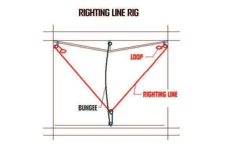
34 Spin Sheet Tie a short section of line through the clew of the spin. Tie one of these to the spin sheet, and begin feeding it through the turning blocks. Start by going to the first one located at the side stay, and then up to the forward cross bar. Bring the excess to the rear of the tramp and repeat the opposite moving to the other side of the boat. Make sure that you follow the arrows on the ratchet blocks for the first side and opposite as you exit the other. Bring the opposite spin sheet end around the forestay and tie off on the spin clew as well. Your first few times it may be advisable to dry run the spin to ensure everything is free prior to hitting the water Righting line Locate the lines labeled righting line Tie a small loop in 1 end of the 6mm line. Feed the other end through the single blocks mounted on the outside extents of the dolphin striker strap. Pull to the rear of the boat (Under the tramp) and then back forward through the single block mounted on the opposite side. Tie another loop. In the center of this righting line attach loosely the 6mm bungee cord. Lash the small turning block to the trampoline tie rod at the center of the boat. Feed the 6mm bungee then through this block and run forward to tie off the end to the dolphin striker post. The bungee should be tensioned so it just keeps the righting line from sagging below the trampoline bottom face. YOU ARE READY TO GO!
35 Sailing and Beaching Remember these important guidelines while using your catamaran: Know what the weather may have in store for you while you will be out. Be familiar with your area and its hazards, especially overhead power lines and underwater obstacles that could damage your craft Know you limitations, and never sail in conditions above your ability putting yourself or others in danger. Always wear a life jacket while sailing Always carry the proper safety gear while sailing When launching into the surf, always head directly into the waves Always know the direction the wind is blowing before launching Secure drain plugs or ports prior to sailing After sailing remove drain plugs to equalize pressure in the hulls Carry your catamaran or use beach wheels with cradles whenever possible to minimize wear. General notes prior to sailing: All crewmembers should receive suitable training before operating the catamaran. The catamaran shall not carry more than the maximum load indicated for the appropriate model and trapezes shall not be used when carrying more than two persons. All inspection ports and drain plugs shall be closed while sailing. Bilge water shall be kept at a minimum. Do not breach watertight compartments. The stability of the craft is reduced when weight is added up high.
36 23.0 Righting after a capsize At some point in your sailing experience, you are likely to experience a capsize. As an owner, familiarize your self with the boat and how to right it, so that you can be prepared in an unpleasant situation. Never sail with out a righting line installed on your boat. If you are not of a sufficient weight to right the boat by your self and sailing single handed, you should carry a righting bag for assistance. As the boat flips over it is important to lower your self to the bottom hull as quickly as possible to help prevent the boat from turning completely over (turtle) Avoid jumping into the sails, or on the boom or hull as damage to the boat or yourself is very likely. Do not let go of the boat as the current or wind may make it impossible for you to be able to get back. If the boat does go turtle, sit on the leeward hull as close to the transom as possible and the bow should rise. If not, pull the righting line around the windward hull and apply gentle pressure until the hull begins to rise. When the boat is sitting flat, make sure all the sail sheets are uncleated. If possible, snuff the spin to make righting easier. To deploy the righting line, pull on the loop located near the upper hull. Pull the line tight stretching the bungee to forward beam. The boat should be pointed with the bows pointed directly or nearly directly into the wind. Move your weight forward or aft to swing the bows in the proper direction prior to righting. With your weight at or just behind the front cross bar, grab the righting line and hike out backwards. Once the mast tip breaks free of the water the boat will come up very quickly. Move your weight inboard to control the speed to the righting boat. As it comes over and is falling freely, release the righting line and grasp a hold of the dolphin striker or the opposite hull to prevent the boat from continuing to capsize in the other direction, and ensure you keep attached to the boat. Once the boat is down and all crew is back on board, organize yourself and your sheets and your are ready to start sailing again.
37 24.0 Trailering and Storage Remember these important guidelines while using your catamaran: Always use trailers and beach dollies with cradles designed to fit the hulls rather than single rollers. Always remove dagger boards, blocks and rigging when trailering. For long distances removal of the rudders and steering system is recommended. For short traveling distances be sure to secure the tiller tie bar so the system cannot turn. Also be sure to secure the rudders in the up position so they cannot be lowered accidentally while trailering. It is recommended that the rudder systems be removed prior to trailering in anything but a very short distance. Tie the boat down snuggly using straps or Tie down lines. Be aware that tying down the boat too tight can result in hull damage. Do not use the dolphin striker for a tie down point or for pulling the boat. Use the main beam instead. Secure both ends of the mast. Be sure to have a red flag attached to the aft end of the mast. To protect against rocks, gravel and road debris, boat covers are recommended. They also provide protection from the weather and the elements. Mooring of your boat is not recommended. Always leave the drain plugs and inspection ports open to avoid the build up of air pressure and causing hull damage when not sailing. Always check for overhead wires when raising or lowering the mast. Contact with electrical power lines can cause serious injury or death.
38 Design Category Design category C2 Coastal and inland coast or protected waters. The Falcon F16 is designed to the F16 class association rules for racing and is set up as a race boat exempt status. Specific Information This catamaran is capable of supporting the crew even when swamped. The Catamaran is also intended to be recovered by the crew after capsize. The F16 rules do not dictate a minimum crew weight for racing. There is a minimum crew weight for righting the boat after capsize. This will vary on the wind and sea conditions. Be familiar with your boat and your capabilities and carry the proper equipment, righting bags or otherwise, anytime you leave the beach.
39 26.0 Maintenance Inspect rigging for signs of wear, corrosion, kinks or frayed wires. Damaged or worn wires can easily break during sailing. Check all threaded connections. The Optional swaged rigging gate fittings are threaded and need to be inspected every sail. Always check beam bolts for proper tension. Always check the steering system attachment points and fasteners are tight and in working order. Ensure all shackles are tight, and all split rings are taped to prevent loss or damage. Periodically inspect shackles, clevis pins and fasteners for wear or loosening. Periodically check the dolphin striker tension. The striker strap should be tight. Before the mast is stepped, there should be a slight 6mm or so upward crown to the forward beam. With the mast raised and the rig tensioned the forward beam should be straight and no sag. Regularly inspect mast for water tightness and to ensure all fittings and attachment points are secure. Check hulls for excessive wear from beaching and dragging. Exposed raw fiberglass should not be visible. A bottom job should be done to replace any lost material before the hull is breached. If your hulls are taking on excessive water during sailing, check for leaks by applying soapy water around the fittings and blowing (with your lungs) into the hull. Do not use compressed air or power equipment such as vacuum cleaners as they will over pressurize your hull and damage it. Remove or replace leaky fittings, clean and reinstall with fresh silicone. If the leak is in an area with a fitting, this should be reglassed using proper methods to ensure bonding. Periodically check all cars, cleats and bearings to ensure they run freely. Replace the bearings as necessary, and rinse thoroughly with fresh water to free up any that may be stuck. Rinse ENTIRE boat with fresh water after each use. Check the sails and trampoline for rips and wear. Repair immediately to prevent further damage. Always keep trampoline lacing tight. Ensure sails are completely dry before storing. If storing for more than a day, loosen batten tension If the boat is to be store for long periods of time, do not leave the rigging at race tight settings. If storing for winter, release diamond wire tension, and for long term mast up beach storage, slightly loosen the rig tension between sails.
40 DESIGN LOADS FALCON F16 Maximum capacity 2 persons total 181 kg
41 FALCON MARINE LLC. CATAMARAN WARRANTY Purpose of Warranty As the purchase of a new catamaran represents a considerable investment, certain conditions are required to protect all parties involved and to prevent abuse of this warranty. This warranty is genuine, and we are here to serve you, so in the unlikely event that you feel your new catamaran has a problem, please tell us early so we can help. Warranty Full Warranty Period, covering the first year from the customer taking possession of the boat for the first time. During the Full Warranty Period, Falcon Marine warrants to the customer that Falcon Marine will at its option repair, replace or adjust free of charge any part of the boat Falcon Marine finds to be defective in factory materials or workmanship when used within the operating limitations of the boat and the provisions of this warranty. Falcon Marine s liability is limited to the repair or replacement of the defective component. No incidental or consequential damages will be allowed. During the second year, Falcon Marine will cover the hulls only on a graduated basis. 50% of the hulls warranty repair cost value will be covered in the warranty settlement. Conditions This Warranty is provided on the following conditions: 1. The defect is not a consequence of the customer s failure to properly use or maintain the boat in accordance with good practice, recommendations or instructions, its capacity or operating limitations or specifications, or to take preventative action to avoid further or secondary damage occurring if a fault becomes evident; 2. The boat must under normal circumstances be delivered at the customer s expense to the factory or its nominated representative for the warranted works as soon as possible after the need for the works becomes apparent; 3. This Warranty will not apply to any defect in, or which is attributable to, or which arises from the use of any modification made to the boat unless the modification has been made by or at the direction of Falcon Marine; 4. This Warranty does not cover damage or wear and tear arising as a consequence of the use of beach rollers, the use of a trailer, friction under the hulls, high speed beachings, collisions or failing to ventilate the boat; 5. All works under this Warranty must be performed by Falcon Marine or its nominated representative at their premises; 6. This Warranty is non-assignable; 7. Only measured sails, spars and equipment by an official class measurement officer appointed by either the class association, builder and/or importer shall be used; 8. The use of non class legal or measured sails, spars and equipment shall void Warranty; 9. This Warranty is subject to the exclusions, operating limitations and responsibilities, which follow.
42 Exclusions This Warranty does not cover: Damage by heat to composite laminates "Print" on the hull surface Print from internal frames on the hull skin Faults resulting from collision, impact or other damage, including heel and other pressure dents to the hull skins. Scratching of any Gel coat surface UV damage or staining in Gel coat surface Blistering or minor stress cracks in the gel coat surface Minor leaks Mast breakage due to capsize Masts breaking due to rigging failure Mast breakage occurring while using a spinnaker Wear and tear on sheets and ropes and rigging Failure of a component due to corrosion Damage to sails due to misuse Damage to sails due to capsize Damage to sails due to mast breakage Stretching and general wear and tear on sails Boat tuning Fittings and hardware - These are not covered by this Warranty, but are covered by any warranty of the fitting and hardware manufacturers Operating Limitations This Warranty applies to boats used for recreational sailing or in organized club or championship racing on inland and coastal waters. It does not apply to defects occurring as a consequence of sailing in wind or sea conditions where a reasonable sailing club or association would not sail, or has abandoned racing due to extreme weather conditions, or to offshore sailing (lake or ocean), or long distance racing events. Boats must be trailed on a trailer fitted with beam hanging supports or cups/cradles approved by the builder and/or importer and shaped to the hulls and padded. Crew weight on the boat must not exceed: 100 Kg One person 180 Kg Two persons
43 Limitiations The buyer assumes all risk and liability whatsoever resulting from the use of the catamaran and its parts. In no event shall, this warranty include nor shall Falcon Marine be liable to the buyer for any indirect, special, incidental or consequential damages or lost profits. The provisions of this warranty and limitation of liability may not be modified in any respect, except in writing, signed by a duly authorized officer or representative of Falcon Marine. This warranty contains a complete and exclusive statement of Falcon Marine's obligations with respect to any of its products. Responsibilities This Warranty does not apply unless the owner has kept the boat in good order at all times, performed any necessary preventative maintenance, regularly inspected rigging for signs of fatigue, and taken immediate action to prevent further damage if any fault appears. Voided Warranty The builder and/or importer may void the warranty for any and all of the above points. The class association, builder and/or importer reserve the right to publish all sail and hull numbers of vessels that have had the Warranty Voided for any or all of the above points.

44 Page 1 of 1 file://s:\ Operations\ Products\F16\OWNERS MANUAL\8 to 1 main sheet.gif 3/8/2010

45 Page 1 of 1 file://s:\ Operations\ Products\F16\OWNERS MANUAL\F16_downhaul_ful... 3/8/2010
46
47
48
49
Owner s Manual. Revision Date: Copyright 2012 Falcon Marine LLC 9008 Marlin St. Cape Canaveral, FL USA
 Owner s Manual Revision Date: 2013-02-06 Copyright 2012 Falcon Marine LLC 9008 Marlin St. Cape Canaveral, FL 32920 USA 321-799-4841 Falcon Marine LLC Falcon Marine LLC Falcon F18 This manual covers the
ASSEMBLY MANUAL HOBIE CATSY
 ASSEMBLY MANUAL HOBIE CATSY HOBIE CAT EUROPE ZI Toulon Est, BP 50 8078 Toulon cedex 9, France Tel : + (0)9 08 78 78 - Fax : + (0)9 08 99 Email : hobiecat@hobie-cat.net - http://www.hobie-cat.net ASSEMBLY
Follow these easy steps to properly assemble your new Zim 420
 Thank you for buying a Zim 420 and welcome to the Zim Sailing family. We are extremely proud of the quality of our boats and the race results are proven. Many of the top sailors are choosing Zim over other
Index 1. Trampoline 2. Main Foils 3. Spinnaker Pole 4. Mast Setup 5. Mast Rigging 6. Rig Tension 7. Trapeze Lines 8. Rudders 9. Boom 10. Main Sheet an
 By User Manual Index 1. Trampoline 2. Main Foils 3. Spinnaker Pole 4. Mast Setup 5. Mast Rigging 6. Rig Tension 7. Trapeze Lines 8. Rudders 9. Boom 10. Main Sheet and Traveler 11. Main Sail 12. Downhaul
OWNER S MANUAL. for Inters and Nacra F-18
 OWNER S MANUAL for Inters and Nacra F-18 Tools you ll need: 9/16 socket Wrench Phillips Screwdriver Allen Wrench (included) HULL ASSEMBLY Place hulls boxes approx. 8 feet apart. Make sure both hulls are
FDR CHRYSLER 16' CATAMARAN (MUSKETEER) The initial rigging of a sailboat is not difficult, but if the boat is strange
 The initial rigging of a sailboat is not difficult, but if the boat is strange") Page of 6 Revised 2/0/76 RIGGING INSTRUCTIONS FDR CHRYSLER 6' CATAMARAN (MUSKETEER) The initial rigging of a sailboat is not difficult, but if the boat is strange to the new owner, or the new owner is
Page of 6 Revised 2/0/76 RIGGING INSTRUCTIONS FDR CHRYSLER 6' CATAMARAN (MUSKETEER) The initial rigging of a sailboat is not difficult, but if the boat is strange to the new owner, or the new owner is
Table of content Introduction 5 1. Part 1. Assembly Tools needed for Assembly Glossary Hulls Mounting the beams 7
 Table of content Introduction 5 1. Part 1. Assembly 6 1.1. Tools needed for Assembly 6 1.2. Glossary 6 1.3. Hulls 7 1.3.1. Mounting the beams 7 1.3.2. Fixing the mast rotation cleats 8 1.3.3. Placing the
Far East Boat Optimist Rigging Instructions
 Far East Boat Optimist Rigging Instructions These instructions are written specifically for Far East Boats Championship and Racing Optimist. Parts of the Optimist PAGE 1 Sprit Wind Indicator Sail Mast
 Table of content Introduction 5 1. Part 1. Assembly 6 1.1. Tools needed for Assembly 6 1.2. Glossary 6 1.3. Hulls 7 1.3.1. Mounting the beams 7 1.3.2. Fixing the mast rotation cleats 8 1.3.3. Mounting
TUNE YOUR SAILS SPEED
 TUNE YOUR SAILS FOR OUTRIGHT SPEED Rev R05 Important Notes l We recommend not exceeding 350lbs total crew weight as this puts excess stress on the mast and the boat. l When sailing, the boat performs best
Topaz OMEGA Rigging Instructions
 Topaz OMEGA Rigging Instructions www.toppersailboats.com TOPAZ OMEGA RIGGING INSTRUCTIONS CONTENTS 02. Introduction 02. Manufacturers Details 03. Maintenance 04. Raising the Mast 05. Attaching the Boom
Pico rigging manual 2007.doc Page 1 of 28
 Pico rigging manual 2007.doc Page 1 of 28 Pico Rigging Instructions The Pico rigging instructions are a guide to rigging your boat. Due to production supplies certain parts may be slightly modified from
1 Tuning Platform Reseating Beam Pads Rudder alignment Noisy Foils Rig Tension...
 Contents 1 Tuning... 2 1.1 Platform... 2 1.2 Reseating Beam Pads... 2 1.3 Rudder alignment... 3 1.4 Noisy Foils... 3 1.5 Rig Tension... 4 1.6 Mast rake... 4 1.7 Spreader rake... 5 1.8 Diamond tension...
ASSEMBLY MANUAL. Last up-date : January 2005 HOBIE MAX RACE
 ASSEMBLY MANUAL Last up-date : January 005 HOBIE MAX RACE List of the parts Necessary tools spanners nr 7 It is advisable to be at least two people to assemble the Hobie Max pair of niversal pliers TABLE
Vanguard Sailboats 300 Highpoint Avenue Portsmouth, RI For the dealer nearest you call SAIL
 Vanguard Sailboats 300 Highpoint Avenue Portsmouth, RI 02871 For the dealer nearest you call 800. 966.SAIL Unpack the major parts listed below and lay them out on a soft piece of ground free of sharp objects.
Dolly wheels in slot #8 for Boat #10.
 Rigging: Laser SAIL SELECTION: The International Laser Class has three different official rigs. Each sail is designed for sailors of different weights. The Standard Rig was designed for sailors weighing
Ref :MMHC14SR_GB Emetteur :MF Date :Dec 2014 Revision : 1 Page 1/18. ASSEMBLY MANUAL : HOBIE CAT 14 Std & Race HOBIE CAT 14 STD & RACE
 Ref :MMHC14SR_GB Emetteur :MF Date :Dec 2014 Revision : 1 Page 1/18 HOBIE CAT 14 STD & RACE Ref :MMHC14SR_GB Emetteur :MF Date :Dec 2014 Revision : 1 Page 2/18 TABLE OF CONTENT Part list... 3 Ropes and
Bladerider X8 Assembly Help Notes
 2.1 Remove All Parts & Have Some Tools Handy Remove all items from the box and identify each part as per the packing sheet and check that nothing is missing. If there is something missing, please email
A Basic Guide to Europe Dinghy Rigging
 The Basics: A Basic Guide to Europe Dinghy Rigging Use the smallest blocks available for the line size. Most of the blocks on your boat will be micro blocks. Examine all of your rigging and ensure that
Club 420 Class Rigging Manual
 Club 420 Class Rigging Manual Performance sailcraft 2000 Inc 2555 Dollard Lasalle, Quebec, H8N 3A9 Tel: 514 363 5050 email: info @ps2000.ca Website: www.ps2000.ca Mast set up Remove the pole and unwrap
3. Sail Kit. Table of Contents: Portland Pudgy Safety Dinghy: 3. Sail Kit
 Table of Contents: 3. Sail Kit Sailing the Portland Pudgy... 1 Sailing Tips... 1 Reducing the Sail Area (Reefing the Sail)... 2 Method 1. Reducing Sail without the Exposure Canopy... 2 Method 2. Reducing
2. Note that the ropes from the rigging board are secured in the cam cleats of the jib fairleads.
 VII 1. Place the hull, bow into wind, on its trailer, a soft surface, or a rigging board. We strongly recommend making a rigging board; it is simple and inexpensive and greatly simplifies rigging and working
Wysiwig - Wayfarer Rigging Guide
 Wysiwig - Wayfarer 8767 - Rigging Guide GENERAL NOTES Before you go afloat, make sure that the self-bailer is closed. It is operated through the cut-out in the starboard floorboard. If you do not close
TUNE YOUR SAILS SPEED. Optimist Tuning Guide. Photo Wavelength
 TUNE YOUR SAILS FOR OUTRIGHT SPEED Photo Wavelength PEAK / HEAD THROAT TACK CLEW THANK YOU for choosing North Sails for your Optimist. Whether you are just starting out in an Optimist you are an experienced
2012-June-12 SECOND DRAFT Hobie Getaway Spinnaker Installation Instructions
 SECTION A: INTRODUCTION This unofficial set of installation instructions was written for a 2009 Hobie Getaway, using a 2012 Hobie Spinnaker Kit 20999020. Note from the Author: I had never seen this kit
OPPI Rigging Guide 3/2008
 OPPI Rigging Guide 3/2008 McLaughlin Boat Works optistuff.com Thanks for purchasing OPPI, the most durable and F-U-N sailboat available. Rigging your OPPI is easy and the following pictures make it a breeze
North Sails Seattle Thunderbird Tuning Guide
 Page 1 of 6 North Sails Seattle Thunderbird Tuning Guide Introduction The following tuning guide is meant as a good starting point in setting up your boat. Since not all Thunderbirds are exactly alike
RIGGING INSTRUCTIONS Let's assume that you have your boat on a trailer when you take delivery from your dealer.
 This is the original owner's manual, written about 1972, and applicable for boats manufactured through 1978. Starting in 1979 a few changes were made in the roller furling jib and forestay arrangement.
M32 CATAMARAN ASSEMBLY MANUAL
 M32 CATAMARAN ASSEMBLY MANUAL 1 M32 CATAMARAN ASSEMBLY MANUAL MANUAL SUMMARY M32 ASSEMBLY Parts and tools Instructions MAST PLATFORM Parts and tools Instructions MAST STEPPING Instructions MAIN HALYARD
Safety Afloat. Before you go sailing:
 RIGGING MANUAL Safety Afloat This instruction manual is not a guide to sailing your craft and it should not be considered suitable for the task of learning to sail a boat. Please read the manual before
INSTRUCTION NO
 INSTRUCTION NO. 14138 Dagger Rigging Instr. P~e 2.of 6 MODEL 244 CHRYSLER "DAGGER" SAILBOAT RIGGING INSTRUCTIONS We, at Chrysler Boat Corporation, congratulate you on your selection of our Model 244 "Dagger"
HOBIE TEDDY ASSEMBLY MANUAL
 ASSEMBLY MANUAL HOBIE TEDDY HOBIE CAT EUROPE ZI Toulon Est, BP 50 83078 Toulon cedex 9, France Tel : +33 (0)494 08 78 78 - Fax : +33 (0)494 08 3 99 Email : info@hobie-cat.net - http://www.hobie-cat.net
Wind Light Moderate Heavy Speed 0-8 mph 9-17 mph 18 + mph
 Hobie 20 Racing Setting - Compiled by Bob Mimlitch, Fleet 23, Dallas, TX Most of the information is from Bob Curry's articles in Catamaran Sailor published by Mary Wells. Wind Light Moderate Heavy Speed
420 Rigging Guide.
 A smaller version of the olympic 470 class, the 420 was formerly a youth development class. It has a good class following, and is a good introduction to performance boats. With a PY number of 1087 it s
J/22 Dave Perry. Based on sailing the POW in the Ft Worth Boat Club (TX) boats in 2006 We sailed with three in the boat
 boats in 2006 We sailed with three in the boat") J/22 Dave Perry Based on sailing the POW in the Ft Worth Boat Club (TX) boats in 2006 We sailed with three in the boat GENERAL Boats spin fast! Boats go fast sideways when downspeed Use weight to help
J/22 Dave Perry Based on sailing the POW in the Ft Worth Boat Club (TX) boats in 2006 We sailed with three in the boat GENERAL Boats spin fast! Boats go fast sideways when downspeed Use weight to help
Falcon 3 145, 170, 195 and Tandem Owner / Service Manual
 Falcon 3 145, 170, 195 and Tandem Owner / Service Manual January 2007 - Second Edition Removing The Sail From The Airframe And Short Packing The Glider Many maintenance and repair procedures will require
HOBIE CAT 16 Easy, Classic, Club & Race
 ASSEMBLY MANUAL HOBIE CAT 6 Photo Pierrick Contin Last Update : January 008 HOBIE CAT 6 Easy, Classic, Club & Race HOBIE CAT EUROPE ZI Toulon Est, BP 50 83078 Toulon cedex 9, France Tel : +33 (0)494 08
Carbo Racing Foil Instruction Manual Unit 0, 1, 2, 3
 Carbo Racing Foil Instruction Manual Unit 0, 1, 2, 3 WARNING!: Strictly follow all instructions to avoid an accident, damage to your vessel, personal injury or death. See www.harken.com/manuals for additional
Date: 00/00/00. Business Name. Organization. Authored By: Warranty Manual
 Date: 00/00/00 Business Name Organization Authored By: Warranty Manual Warranty and Maintenance Terms & Conditions (Assembled boats) Important Notice about this manual We thank you for choosing a Nacra
Tuning Guide January 2012
 Tuning Guide January 2012 www.skud.org This tuning guide has been prepared by the IACA SKUD 18 Committee to assist new sailors in the SKUD 18 class to prepare their MkI or MkII boat to a competitive level
CONTENTS INTRODUCTION
 INTRODUCTION This owner s manual is provided to ease assembly, maintenance and use of your Prindle Catamaran. We believe these instructions portray the simplest methods. Do it our way the first time and
Set-up and Tuning Notes: 17 September 2012
 Set-up and Tuning Notes: 17 September 2012 This document is being continually updated. Please check the release date above regularly to ensure you have the most recent edition. We appreciate any feedback
T 10 Tacking Ver
 T 10 Tacking Assume sailing upwind in moderate conditions Ensure Jib sheets are clear both in the cockpit and forward. Ensure new course is clear of other boats, shipping, and navigation hazards. Ensure
J/70 Building Specification
 DECK, HARDWARE AND FITTINGS 1 FRP Composite deck 2 Indeck furler unit 3 Bow "U" bolt mooring eye (stainless) Option for one 6" (152mm) mooring cleat in lieu of eye. 4 Shroud chainplates (stainless) (BSI
Rigging Manual. 1 Parts of the Hull. 2 Parts of the Sail. 3 Sunfish Mast Kit. 4 Bailer Installation. 5 Ratchet Block Installation
 SUNFISH SUNFISH RACE SUNFISH Rigging Manual 1 Parts of the Hull Go-fast tip number one: Read this rigging guide first. 2 Parts of the Sail 3 Sunfish Mast Kit 4 Bailer Installation 5 Ratchet Block Installation
COASTAL IN-BOOM FURLING SYSTEM. Installation Manual
 COASTAL IN-BOOM FURLING SYSTEM Installation Manual 1 TABLE OF CONTENTS Page Number 3. Disclaimer 4. Components packing list & required tools 5. Gooseneck bracket location 6. Installation sail track 7.
North Sails One Design Atlantic Tuning Guide
 North Sails One Design Atlantic Tuning Guide North Sails One Design's Atlantic tuning booklet will cover mast tuning, sail care, boat preparation and sail trimming tips. If you have any questions or need
Melges 24 Sailing Guide
 RACING GUIDES www.ullmansails.com Upwind Sailing Melges 24 Sailing Guide The Melges is most efficient when sailed as flat as possible. Excessive heel causes leeway which is slow. The skipper must work
F-27 RIGGING GUIDE EXTRACTED FROM ORIGINAL F-27 SAILING MANUAL
 F-27 RIGGING GUIDE EXTRACTED FROM ORIGINAL F-27 SAILING MANUAL By Ian Farrier not be possible if the towing vehicle is a van. When trailering, allow extra distance for stopping. Watch also for low bridges,
41. Barbour Outhaul Cleat 54. Drain Plug
 Thank you for choosing the Isotope / Cheshire Catamaran. Following these instructions will help you get years of performance and sailing enjoyment out of your boat. These cats are hlgh-performance sailboats,
600 / 600FC OWNER'S MANUAL
 PROGRESSION 600 / 600FC OWNER'S MANUAL Issue 2 / Version E - Dec. 10, 1997 Copyright 1997 GAMMA Sports - All Rights Reserved PROGRESSION 600 / 600FC OWNER'S MANUAL TABLE OF CONTENTS PAGE 1... WARRANTY
Daysailer Tuning Guide
 Daysailer Photo Deb McCaffrey For any question you may have on tuning your Daysailer for speed, contact our experts: Brian Hayes 203-783-4238 brian.hayes@northsails.com Chris Snow 619-226-1415 chris.snow@northsails.com
OWNERS MANUAL. Model Shown with optional Primary Mooring Cleats. Portable Mooring System SAFETY OPERATION MAINTENANCE PARTS
 OWNERS MANUAL Model 2400 Shown with optional Primary Mooring Cleats. Portable Mooring System SAFETY OPERATION MAINTENANCE PARTS CAUTION: Before using your new Pier Tender, read rules for Safety, Operation,
Sanibel Owners Manual
 Sanibel 36-600 Owners Manual TM Specifications Length (Hull):... 36 inches Height (Mast):... 51.5 inches Height (Overall):... 69 inches Beam:... 7.5 inches Radio: JR Beat Gear w/sail winch servo Sail area:
Page 1. Single Scull Car Rack Assembly and User s Manual " "
 Page 1 Single Scull Car Rack Assembly and User s Manual Page 2 Items in the box: (2) V cradles (2) 4 rails (1) 1 3/4 X 18 rail coupler (4) 1/4-20 X 4 1/2 bolts (2) 1/4-20 X 2 1/2 bolts (12) 1/4 flat washers
E Scow Racing and Rigging Manual
 E Scow Racing and Rigging Manual Written by Mark Ehlers Editing and content revisions by Andrew Bartling Aspects of Sailing E Scows Crew weight should never exceed 675lbs. The target weight for 4 people
Y-FLYER TUNING GUIDE ONSHORE ADJUSTMENTS
 Y-FLYER TUNING GUIDE Congratulations on your purchase of North Y-Flyer sails. We are confident you will find superior speed over all conditions. Your sails are designed to be fast, as well as easy to trim
OWNER S MANUAL OWNER'S MANUAL TABLE OF CONTENT. 1. Introduction. 2. EC Documentation a) Certificate of homologation b) Declaration of conformity
 Certificate of homologation b) Declaration of conformity") OWNER'S MANUAL TABLE OF CONTENT 1. Introduction 2. EC Documentation a) Certificate of homologation b) Declaration of conformity 3. Description a) Hull identification b) Design category c) Technical data
OWNER'S MANUAL TABLE OF CONTENT 1. Introduction 2. EC Documentation a) Certificate of homologation b) Declaration of conformity 3. Description a) Hull identification b) Design category c) Technical data
Rigging guide for the Swift Solo Volume 1 (mostly boat rigging)
") Rigging guide for the Swift Solo Volume 1 (mostly boat rigging) Thanks to Greg Ryan for the drawing 5/28/2004 1 Index Page 3 Preface and Safety 4 Quick line measurements you ll need 5 Spinnaker pole launcher
Rigging guide for the Swift Solo Volume 1 (mostly boat rigging) Thanks to Greg Ryan for the drawing 5/28/2004 1 Index Page 3 Preface and Safety 4 Quick line measurements you ll need 5 Spinnaker pole launcher
Thistle Tuning Guide
 For any question you may have on tuning your Thistle for speed, contact our experts: Ched Proctor 203-783-4239 ched.proctor@northsails.com Brian Hayes 203-783-4238 brian.hayes@northsails.com onedesign.com
Most sail with 5 or 6 in the boat. Here are the names I will use for the various positons (from the back forward):
:") Racing the Oakcliff Sailing Match 40 s Dave Perry notes May 17, 2016 There are many ways to do things. Here are some notes on how we do things on the Match 40 s at Oakcliff. Most sail with 5 or 6 in the
Racing the Oakcliff Sailing Match 40 s Dave Perry notes May 17, 2016 There are many ways to do things. Here are some notes on how we do things on the Match 40 s at Oakcliff. Most sail with 5 or 6 in the
Highlander Specifications
 Highlander Specifications July 22, 2012 Highlander Specifications The intent of this section is to clarify and add to what is shown in the official plans. In case of conflict between these specifications
PT 11 trouble-shooting and maintenance.
 PT 11 trouble-shooting and maintenance. Does your rudder not stay down?...your back seat slip off?...your knobs tight and your leather pads loose? Maybe we can help. We have used our PT 11 s hard enough
HOW TO RIG A CORMORANT
 HOW TO RIG A CORMORANT Page 1 of 6 Instructions adapted from Cormorant Owner s Handbook 1 Ensure that peak halyard, throat halyard and topping lift are attached to the mast as shown in Fig. 1. 2 Set-up
CONTENTS INTRODUCTION
 INTRODUCTION This owner s manual is provided to ease assembly, maintenance and use of your Prindle Catamaran. We believe these instructions portray the simplest methods. Do it our way the first time and
SPARE PARTS WORKBOOK
 SPARE PARTS WORKBOOK Hull Parts - Bow Area 0 0 RS Feva Foredeck FEV-HF-00 Pozzi pan screw x / FIX-S-P0 Washer M 'A' FIX-W-00 00mm Black Dacron Patch ZDP00 Allen Hatch Inch: Sealing Ring A Pozzi pan screw
Hobie Island Spinnaker Instructions
 Hobie Island Spinnaker Instructions Please read through the instruction manual before using this product. 2 Installation Components 1. 2. 1. Swivel Cam Cleat 2. Mount for Cleat w/ Hardware 3. Padeye w/
Setup &Tuning guide. Updated 1st February 07
 Setup &Tuning guide Updated 1st February 07 Boat preparation Tape a piece of batten to the backstay ram with a calibrated scale drawn on it. This will allow you to reproduce the same backstay settings
OPERATIONAL CHECK LIST
 www.spinnakersailing.com (650) 363-1390 OPERATIONAL CHECK LIST https://twitter.com/#!/spinnakersailin http://www.facebook.com/spinnakersailingrwc http://www.spinnakersailing.com/newsletter.html Dear Sailor,
2,500/4,000 LB Easy Riser Vertical Cable Feighner Lift
 2,500/4,000 LB Easy Riser Vertical Cable Feighner Lift CAUTION - PUT SAFETY FIRST 1. Before attempting to install or operate this lift, study and fully understand the proper operating procedures and safety
QUALITY ALUMINUM BOAT LIFTS, INC. INSTRUCTIONS. Dominator Lake Lift
 INSTRUCTIONS Dominator Lake Lift PHONE:251-986-3882 * FAX:251-986-3136 QABLDOMINATORINST.2014 P a g e 1 Quality Aluminum Boat Lifts, INC. Installation Instructions: Dominator Lake Lift Thank you for your
CII Rigging suggestions
 CII Rigging suggestions This mini-manual uses photographs of the final prototype sail and the final pre-production mast. Where changes occurred between these and the production units, they are described
Kayaking Bob s Tandem Island SpraySkirt Kit Installation Instructions
 Kayaking Bob s Tandem Island SpraySkirt Kit Installation Instructions Copyright 2011 by R. E. & D. L. Conlon Kit Contains: Right & Left SpraySkirts 3 Long Black Wire Ties* 3 Short Black Wire Ties* 1 3/16
ETCHELLS RIG SET UP FOR PC-M/PC+/BF MAIN, DC270/GM JIBS,.5oz VMG, FULL RADIAL and.5oz/.75oz BIRADIAL SPINNAKERS
 ETCHELLS RIG SET UP FOR PC-M/PC+/BF MAIN, DC270/GM JIBS,.5oz VMG, FULL RADIAL and.5oz/.75oz BIRADIAL SPINNAKERS 1. MAST STEP Jan 2008 5.360mtrs measured from the transom/deck intersection to the aft edge
RUDDER KIT INSTRUCTIONS
 A I N S T R U C T I O N S RUDDER KIT INSTRUCTIONS TARPON 0/40/60/60i The Tarpon series is designed as a high performance sit-on-top kayak tailored for the sport paddler. Our rudder system is designed to
INTERNATIONAL SUNFISH CLASS ORGANIZATION CLASS RULES
 INTERNATIONAL SUNFISH CLASS ORGANIZATION November 2017 CLASS RULES 1. GENERAL The design and development of the Sunfish sailboat was directed to the creation of a one-design class where the true test is
Contents 1. Components Introduction Preparation Hull Foredeck Mast Boom...
 Rigging Manual V5 Contents 1. Components...1-6 1.1 - Spars...1 1.2 - Rudder pack...1 1.3 - Rigging pack... 2 1.4 - Rope pack... 3 1.5 - Asymmetrical spinnaker pack... 4 1.6 - Symmetrical spinnaker pack...
For ELECTRIC ANCHOR WINCH Models: T Pontoon 35 T sw Salt Water Series Coastal 35
 INSTALLATION AND OPERATING INSTRUCTIONS ANCHOR WINCHES For ELECTRIC ANCHOR WINCH Models: T10109-35 Pontoon 35 T10102-35sw Salt Water Series Coastal 35 If you have any questions or difficulty installing
HOBIE TEDDY ASSEMBLY MANUAL
 ASSEMBLY MANUAL HOBIE TEDDY HOBIE CAT EUROPE ZI Toulon Est, BP 50 83078 Toulon cedex 9, France Tel : +33 (0)494 08 78 78 - Fax : +33 (0)494 08 3 99 Email : info@hobie-cat.net - http://www.hobie-cat.net
TUNE YOUR SAILS SPEED. J/80 Tuning Guide. Rev R12a
 TUNE YOUR SAILS FOR OUTRIGHT SPEED J/80 Tuning Guide Rev R12a This Tuning Guide was written to help you get the most performance out of your J/80. North Sails has been sailing J/80s since they were first
Instruction Manual. Features. Specification: Length: 730mm Width: 500mm Height: 1000mm Sail Area: 0.15m 2. Weight: 692g (w/o battery & receiver)
") AN UNBELIEVABLE SPEED MACHINE Instruction Manual Features Specification: Length: 730mm Width: 500mm Height: 1000mm Sail Area: 0.15m 2 Weight: 692g (w/o battery & receiver) Thank you for purchasing your
AN UNBELIEVABLE SPEED MACHINE Instruction Manual Features Specification: Length: 730mm Width: 500mm Height: 1000mm Sail Area: 0.15m 2 Weight: 692g (w/o battery & receiver) Thank you for purchasing your
The Mirror, Rigging and Improving Performance. Series One, Basic Improvements
 The Mirror, Rigging and Improving Performance Short notes to help you towards that elusive goal of perfect performance. Series One, Basic Improvements Angus Carlisle Mirror Fleet Captain, 2005 Ripon Sailing
2019 MADONE ASSEMBLY MANUAL
 2019 MADONE ASSEMBLY MANUAL 2019 MADONE Rim brakes and Di2 drivetrain Rim brakes and mechanical drivetrain Disc brakes and Di2 drivetrain Disc brakes and mechanical drivetrain TABLE OF CONTENTS Common
Hansa 2.3 Rigging Guide
 Hansa 2.3 Rigging Guide Manufactured by Hansa Sailing Systems Pty Ltd ABN 56 079 318 031 4/4 Cumberland Avenue SOUTH NOWRA NSW 2541 AUSTRALIA Postal: PO Box 5048 NOWRA DC NSW 2541 Telephone: +61 2 4403
SASK-A-POLE OWNERS AND USERS MANUAL
 SASK-A-POLE OWNERS AND USERS MANUAL GENERAL INFORMATION The Saskatchewan Abilities Council s Sask-a-Pole accessibility and transfer aid is designed to help provide safe and easy access to chairs, beds,
ODOM CLASS SPECIFICATIONS
 ODOM CLASS SPECIFICATIONS Effective March 1, 2004 1. GENERAL 1.1 Purpose of the Measurement Rules 1.1.1 The ODOM is a One-Design Class as defined by the American Model Yachting Association (AMYA). However,
DO NOT use any Alien Flier Zip Line Products or Accessories until you read and understand these SAFETY WARNINGS!
 ! WARNING DO NOT use any Alien Flier Zip Line Products or Accessories until you read and understand these SAFETY WARNINGS! A zip line can be very dangerous. Do not use this kit if you do not understand
(PLEASE CONTACT YOUR LOCAL DEALER or CUSTOMER SERVICE FOR WARRANTY INFORMATION)
") RUDDER KIT SOLO KAYAKS IMPORTANT: Tandem models will require the Wildy Supplemental kit in addition to this kit. The Supplemental kit provides extension straps and extra footbraces that allow rudder positioning
RUDDER KIT SOLO KAYAKS IMPORTANT: Tandem models will require the Wildy Supplemental kit in addition to this kit. The Supplemental kit provides extension straps and extra footbraces that allow rudder positioning
Viper 640 Tuning Guide
 Viper 640 Tuning Guide For any question you may have on tuning your Viper 640 for speed, contact our experts: Ched Proctor 203-877-7627 ched.proctor@northsails.com Zeke Horowitz 203-783-4241 zeke.horowitz@northsails.com
Laser Rigging Basics St. Jamestown Sailing Club
 Laser Rigging Basics St. Jamestown Sailing Club This rigging guide is intended as a reference of Laser rigging best practices. It is not a substitute for personal instruction and you should attend a Laser
Tuning C420 Sails By Brian Doyle and Dave Kirkpatrick
 Tuning C420 Sails By Brian Doyle and Dave Kirkpatrick In the spring of 2003, the Club 420 Class sails were redesigned to provide a better competitive and useful lifespan. Now that several events have been
602 STRINGING MACHINE OWNER'S MANUAL
 PROGRESSION 602 STRINGING MACHINE OWNER'S MANUAL AL Issue 1- April 2000 Copyright 2000 GAMMA Sports - All Rights Reserved PROGRESSION 602 STRINGING MACHINE TABLE OF CONTENTS PAGE 1... WARRANTY PAGE 2...
TUNE YOUR SAILS SPEED
 TUNE YOUR SAILS FOR OUTRIGHT SPEED J/70 Tuning Guide Rev. R02 After countless hours sailing, testing and competing in the J/70 One Design, North Sails has updated our tuning notes and tips in an effort
Set Up for Epsilon, Z Spar, Needlespar & Goldspar Masts
 Winning in the 470 by Ullman Sails Overview The 470 is very sensitive to wind and sea conditions. Optimizing your 470 s performance requires considerable adjustments in mast rake and tuning. This guide
TUNE YOUR SAILS SPEED. Viper 640 Tuning Guide. Rev. R03b
 TUNE YOUR SAILS FOR OUTRIGHT SPEED Mast Tuning Tuning Guide for the Carbon Mast SET SPREADER ANGLE Check spreader angle by placing a straightedge or string from shroud to shroud at the spreaders. Measure
HOBIE GETAWAY OWNER S MANUAL HOBIE GETAWAY
 OWNER S MANUAL 1 HOBIE GETAWAY WELCOME TO THE HOBIE WAY OF LIFE Congratulations on the purchase of your new HOBIE Getaway and welcome to the HOBIE sailing family. The HOBIE Getaway cannot be outgrown.
Hobie s business of fun had begun.
 Hobie Cat T1 Manual In 1950, Hobie s dream was born in his parents garage when he decided to apply his love of woodworking to the sport of surfing. Dad backed out the Buick... Hobie carved out his very
AUSTRALIAN COBRA CATAMARAN ASSOCIATION RULES AND RESTRICTIONS IMPOSED ON COBRA 5 METRE CATAMARANS AS AMENDED TO JANUARY 1996
 AUSTRALIAN COBRA CATAMARAN ASSOCIATION RULES AND RESTRICTIONS IMPOSED ON COBRA 5 METRE CATAMARANS AS AMENDED TO JANUARY 1996 General Revision 1.2 - November 1997 1. By agreement with the designer of the
Rhodes 19 Tuning Guide
 Rhodes 19 Tuning Guide Jud Smith jsmith@doylesails Tomas Hornos tomas@doylesails.com Send order forms to: onedesign@doylesails..com SETTING UP YOUR RHODES 19 FOR DOYLE SAILS BEFORE STEPPING THE MAST 1.
X-6 STRINGING MACHINE OWNER'S MANUAL. Issue 1 - May Copyright 2004 GAMMA Sports - All Rights Reserved
 X-6 STRINGING MACHINE OWNER'S MANUAL Issue 1 - May 2004 Copyright 2004 GAMMA Sports - All Rights Reserved OWNER'S MANUAL GAMMA X-6 TABLE OF CONTENTS PAGE 1... WARRANTY PAGE 2... FEATURES PAGE 3...ASSEMBLY