Version 7 YACHT PRODUCT CATALOGUE. Rig solutions for yachts ranging from 28 to 80 feet.
|
|
|
- Deborah Gray
- 5 years ago
- Views:
Transcription

1 Version 7 YACHT PRODUCT CATAOGU Rig solutions for yachts ranging from 28 to 80 feet.
2 product catalogues e hope this eldén Yacht product catalogue will be helpful for you finding accessories and spare parts for your rig. This is one of five product catalogues and it presents our range of products for approximately 28 to 80 yachts. If you need any of the other catalogues you are welcome to pick them up from your local dealer or to download from Version 7 DÉN DCK HARDAR Deck hardware Blocks, cleats, swivels, tracks, travellers, deck organizers and accessories. DCK HARD AR 1 Keelboat Version 1 K BOAT Rig systems and accessories for 18 to 2 feet boats. PRODUCT CATAOGU 1 Dinghy DINGHY Rig systems and accessories for dinghies PRODUCT CATAOGU Carbon Presents the entire carbon product range from dinghies to yachts. 2 CARBON PAR
3 Introduction 4 Masts 8 Cross beams for catamaran 0 Booms and Rodkickers 2 Furling masts manual and electric drive 74 Furlex jib furling and reefing system 8 eldén CX and GX 104 Hydraulic 114 pinnaker and gennaker 128 ights 14 Rig fittings 10 Just smart 178 eldén worldwide. Useful publications. 18 Contents in alphabetical order 188 The information and specifications contained in this catalogue are subject to change without prior notice. 3

4 4


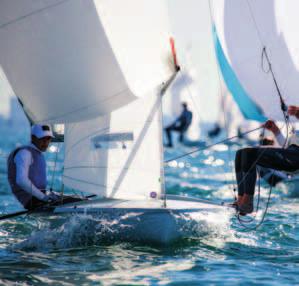
5 DINGHIKBOATYACHT Making the best yacht rigging systems in the world is only part of our business. ith a large number of championship medals in the Olympics, orld Championships, uropean Championships and national championships, eldén has proved to be Number One in rig systems for dinghies and keelboats. o no matter the size of your boat, whether you push your equipment to the very limit, or just enjoy leisurely cruising, go eldén and you ll benefit from reliable top-class gear.

6 Right from the start eldén was founded in 190 and it has grown from a small company into the world leader, with manufacturing in urope, the UA and Asia. Precise, meticulous work has always been a characteristic of eldén. Our manufacturing methods, tools and instruments have been specially developed to meet the demands of large-scale, cost-effective, quality production and the high demands of sailors around the world. However, we still carry out the same heeling tests as we did back in 19. e started by doing things in the right way, and that is how we have continued. Heeling test in 19. The righting moment of the boat is measured at 30 heel. Heeling test today. Materials change. Good methods don t. Unspecified changes can cause failures ach rig is carefully designed and sized for the boat in question. e base our mathematical dimensioning on the righting moment of the boat and the boat designer s proposed sail plan. The wishes of the boat owner determine the way the rigging system is equipped. ith nearly 0 years of experience, we have built up a tremendous experience bank for the use of our rig designers. As a result, the boat and rig form a wellfunctioning whole. Because of this, it is important that even seemingly unimportant details on the boat or rig are not changed without first consulting us, as even small changes can lead to big problems. ach mast and boom from eldén has a unique serial number. This is engraved in the lower end of the mast extrusion and the front end of the boom extrusion. Quote this number if you want to discuss details relating to your rig.

7 Give us the facts The key to a correct rig calculation is the quality of the input data at our disposal. This data consists of hard facts, plus what we can learn by listening very carefully when talking to the customer. The eldén Rig Fact sheet has proven to be a simple and effective way of gathering all the facts required to calculate the mast, boom and standing rigging. It is where you note the data on the envisaged type of rigging, the main dimensions of the sail plan, the location of the chain plates and the righting moment of the boat (or the correct information to help us calculate the righting moment). The eldén Rig Fact sheet is available on our web site, Attention to detail In our search for perfection, no detail is considered too small. This applies to everything, from the choice of materials to stringent testing of the finished product. eldén s business philosophy can be sued up as quality thinking and system thinking, and a continuous quest to achieve the best possible function for each product. This catalogue provides an overview of this holistic approach. Read on to learn about our MD full-batten system, our unique inboard ends, the load distributors in the Furlex jib furling system, and a great many other features and details. 7

8 8 eaders in every detail very eldén rig is carefully thought out, down to the last detail. All the way from the materials and functions of the different parts of the rig, to dimensioning the right rig for each individual boat. ach individual component contributes to the performance of the whole rig. That is the eldén way experienced yachtsmen behind every aspect of design, product development and production.

9 Masts Mast sections 10 eldén carbon spars 12 Headboxes 1 Forestay and backstay toggles 19 Forestay fittings and halyard routing 20 Running backstay attachments 29 preaders 30 ail entry 37 The MD full-batten concept 38 Keel-stepped and deck-stepped masts 41 Deck ring system 47 inch pads 48 Cleats 48 All our standard rigs are custom made xtruded aluminium is an excellent material for making masts. This is where eldén has earned its reputation as world leader in mast making. Today eldén offers a full range of masts and rig equipment in both aluminium and carbon including booms, spinnaker poles, Rodkicker rigid vangs, furling systems, rig fittings and deck hardware. All rigs are custom-made, through every calculation and detail, for each individual boat. e know how much depends on the rig, and there is no room for compromise. 9

10 Mast sections C-sections and F-sections oads generated by the crew (mainsheet, vang, outhaul, Cunning ham etc.) are transferred to the mainsail and on to the mast. As the mainsail is designed according to the expected curve of the mast, a longitudinally stiff mast allows for less luff curve of the sail. Instead, this sail area can be added to the roach of the sail, where it is subjected to the wind and more efficient. The longitudinal rigidity of the mast section makes for higher forestay load created by tensioning the backstay. Running backstays can often be avoided. The risk of mast pumping is also reduced. Mast section ection dim. l y cm 4 l x cm 4 all thickness eight kg/m y cm 3 x cm 3 ail groove ail groove for bolt rope* C-sections C1 1/ ± 0.7. ± 0.7 ee page C17 17/ X C / C / C / C24 24/ C24 24/ C28 28/ C / MD car ail slides Art. no or C / / ± C3 3/ / F-sections RA F17 17/ ee table on next page. ** F / X Y Y RA/RB F / RA/RB F / RB F24 24/ RB/RC F2 2/ RB/RC F28 28/ RB/RC F30 30/ RC/RD F / / RD F / / RD F40 408/ / * If a traditional bolt rope is to be used, a plastic profile ( 3-710), as well as a sail feed (0-2-01) must be added to the luff-groove on the mast. ** For more detailed information on eldén s furling masts, see pages 74-8 or ailmakers Guide ( 10
11 Major diameter (211 ) Mast section measurements are given as follows: Major diameter/minor diameter (i.e. 211/110). This will help identification and the use of correct measurements. The major diameter of the mast can usually be found in the number engraved at the mast heel. For example K23-C Measurement points Minor diameter (110 ) pace for luff tape uff groove Furling mast luff extrusion eight A B kg/m RA ±0.2.0 RB ± A Ø B RC ± RD ± Big luff curve. ess roach. tiff mast. Bigger roach for more projected area. 11

12 eldén carbon fibre masts the perfect mix of craftsmanship and modern production technology
.")


13 MOR PD ITH FAT FIBR Our carbon spars are designed using the latest finite element analysis backed by many years of solid engineering experience. Our unique production method gives a unique look. e call it Mandrel Filament Moulding (MFM). The process is fully automated and computer controlled for ultimate accuracy, repeatability, efficiency and that stunning Viper pattern. eldén produce over 400 carbon masts per year as well as booms, poles and bow sprits for boats including high performance skiffs, racing keelboats, IRC race boats and some of the world s most prestigious cruising yachts. ith more sailors choosing eldén carbon spars, the pattern is obvious. For more detailed information, please see our Carbon catalogue.

14 eldén carbon spars For everyone who cannot resist speed Carbon composite combines stiffness and strength with low weight. eldén lowweight carbon spars have accentuated longitudinal stiffness. This means that forestay tension can be substantially increased. All experienced racing sailors know what this means in terms of increased upwind performance. The combination of greater stiffness and reduced weight will bring you beyond the speed limits. 14


15 X Y Mast section ection dim. l y GN 2 l x GN 2 all thickness eight kg/m CC / ,0 1, CC / , 2, CC / ,0 2, CC / , 2, CC / , 2, 72 2 CC / ,2 3,1 8 1 CC / , 2,9 8 1 CC / ,2 3, CC / , 3, CC / ,2 3, 1 82 CC / ,2 3, CC / ,8 4, CC / ,2 4, CC / ,8 4, CC / ,4, CC / ,8, CC / ,4, CC / ,4, CC / ,0, CC34-3/ CC / y cm 3 x cm 3 Black pigment in the epoxy protects against UV radiation. Clear varnish, or paint, provide extra UV protection and preserves the exclusive appearance. 1


16 Headbox C211-C304 and F212-F40 The headboxes are equipped with a separator, to make it easy to access the top sheaves. Just loosen the separator, which also works as a locking plate, and the sheaves can easily be lifted up for inspection or replacement. This means that you can replace the sheaves without unstepping the mast and removing the headbox. The separator is slightly angled at its front end to lead the spinnaker halyard on to the sheave. The headbox fitting has a gently rounded halyard lead for a masthead spinnaker or gennaker. Conventional spinnaker arrangement with one or two halyard blocks is, of course, still an option. An instrument base is available for both straight and angled tops. The instrument base is designed to make it easy to dismantle the mid section when you need to access the mast top sheaves. ell organised and easily accessible. eparator locks sheaves and also controls spinnaker halyard. Top access, without unstepping the mast and removing the headbox. 1

17 Mid section of instrument base easily removed to access top sheaves. 17
18 Headbox fittings Description Dimensions length x width Notes Instrument base 197 x 74 For 0º headbox Fractional rig C211-C304 Masthead rig C17-C28, F17-F Instrument base 197 x 74 For 1 headbox C211-C304, F194-F Aerial bracket assy 1x8x20 For 0º headbox index crane 13 x 74 Incl. pop rivets (4.8 x 1.) to be fitted on aft edge of headbox. For 1 headboxes, bend crane for horizontal position index base on top of "Aqua" tricolour (white) lamp. Ø vindexfäste på 3-färgslant 08-8 vindexfäste på 3-färgslant For tricolour lamp and anchor light. 0 x 30 x 3 For 0º headbox All sections Instrument base 100 x For 0º headbox All sections Instrument base 180 x For 0º headbox All sections Instrument base 10 x For 1º headbox All sections Instrument base 180 x For 1º headbox All sections index and anchor light base. 20 x 30 For 1º headbox All sections index extension Bases for tricolour lamp and anchor light. 0 x 30 x 3 For 1º headbox All sections (except C304 and F30) Instrument base 100 x 40 For 1º headbox All sections (except C304 and F30) Instrument base including 2 supports Instrument base including 2 supports. 0 x 80 To be combined with the following brackets: For 0º headbox 08-2, 08-1, For 1º headbox 08-27, 08-41, 08-3, x port and starboard wings with support strut. ength = 00 For 0º headbox without base. For 1º headbox shall base be used. 18
19 Forestay and backstay toggles Y Y X C-section X F-section C-sections and F-sections = ingle toggle D = Double toggle = ingle toggle D = Double toggle Forestay and backstay toggle Backstay and triatic toggle ire Mast section idth Masthead Term. pin Max. triaticdia. max pin dia. (bush) dia. wire dia. 4 C C1, C17, F C193, F D C1, C17, F C193, F194, C D F212, C227, F228 C24, F24, C F2 7 C17, F17, C F194, C211, C211 Tpr D D C227, C227 Tpr C24, F24, C F2 8 C24, F24, C F28, C24 Tpr D C24 Tpr, C28 Tpr C24, F24, C F2, C28, F D D C304, F30 C17, F17, C F194, C211, F D C227, F C211, F212, C F228 C24, F24, C F2, C28, F D D C304, F D C24, F24, C F2, C28, F D D C304, F30, C321, F D C304, F30, C321, F D triatic Tpr = Tapered top 19
20 Forestay fittings and halyard routing Cutter stay on masthead rigs On fractional rigs the forestay fitting is either fitted directly on to the mast or combined with the halyard box (eldén combi boxes). The forestay is often attached to the fitting with a toggle. The stainless strap of the combi box wraps around the whole box and serves as a reinforcement that takes up the loads from the forestay. It also locks the sheave axles in the right position. The combi box penetrates deep inside the mast, allowing the spinnaker halyard to run freely past the genoa halyard. This solution substantially increases the durability and service life of the halyards. ee illustration on page Triple combi box Combi box eparate genoa box Pin pinn. halyard Halyard lead for Furlex Genoa halyard ire Combi box Max rope dia. Genoa box Genoa box Max dia., dia. single double rope/wire, (only rope) / R190, R213: (12) * / (1) * Bushing for clevis pin, (in case you drop it). Triple combi boxes ire dia. Triple combi box Characteristics Max spinnaker halyard dia., Max genoa halyard dia., rope/wire (only rope) Furlex halyard lead Furlex halyard box, single Furlex halyard box, double Max. dia., rope/wire (only/rope) x spinnaker halyard 12 10/ /4 1 genoa halyard (12) (12) 20

21 Combi box combined with double genoa box

.")
22 crew O-22/-3: 1-1 O-0: 1-21 asher (PA) O-22/-3: O-0: oop O-22: O-3: O-0: heave box pinnaker Halyard lead O-fitting O-fitting. heave box Genoa halyard O-fittings To be combined with... ire Fitting imits Genoa box Genoa box pinnaker pinnaker ingle Double dia. single double box box halyard halyard single double lead lead 4 O Max F212, C x R232, R20, * Intended only for rope (not rope/wire). R290 O O Max F212, C or Not 274, R232, * R20, R290 8 O Max C heave box pinnaker For more information about halyard leads, see page 2. Halyard lead T-terminal. heave box Genoa halyard Backing plate for T-terminal To be combined with... ire Genoa Genoa pinnaker pinnaker ingle Double dia. box box box box halyard halyard single double single double lead lead 22 Note. Never put a forestay fitting or a halyard box in the tapered area. Applies to masts with -sections where the weld for the taper is on the forward side of the mast * x * * * / /R-sections * * / or 7/R-sections * ** * / /R-sections * * Min F17 ** Intended only for rope (not rope/wire).

23 Chafe guard heave box pinnaker Forestay fitting incl. lead block with stand-up spring Nose tang with chafe guard. To be used where the halyard is led above the nose tang. On fractional rigs with a single box for the spinnaker halyard, a good solution is to have its lead block attached to the forestay fitting. eldén offers complete kits with forestay fitting, including the appropriate lead block. eldén also offers sheave box kits complete with fasteners. Nose tang fitting heave box Genoa halyard Nose tang fittings, incl. toggle ire dia. Description Toggle length Nose tang fitting/ toggle Nose tang fitting/ toggle/chafe guard Nose tang fitting/ toggle/lead block 7 Nose tang fitting/ toggle Nose tang fitting/ toggle/chafe guard Nose tang fitting/ toggle/lead block 8 Nose tang fitting/ toggle Nose tang fitting/ toggle/chafe guard Nose tang fitting/ toggle/lead block 10 Nose tang fitting/ toggle Nose tang fitting/ toggle/chafe guard Nose tang fitting/ toggle/lead block 12 Nose tang fitting/ toggle Nose tang fitting/ toggle/chafe guard Nose tang fitting/ toggle/lead block 14 Nose tang fitting/ toggle Nose tang fitting/ toggle/chafe guard 1 Nose tang fitting/ toggle Nose tang fitting/ toggle/chafe guard To be combined with... pring for spinnaker block Genoa box single Genoa box double pinnaker box single pinnaker box double ingle halyard lead or Double halyard lead 2x or * x or * or RM<120 knm RM< RM<120 knm RM<10 knm RM<120 knm RM<10 knm 2x ** or * Intended only for rope (not rope/wire). ** Only to control genoa halyards. 23


24 The routing of halyards is always important, but parti - cu larly so on yachts with jib furling and reefing systems. A properly installed halyard box provides optimum hal yard routing. eldén offers a complete range of halyard boxes. You can choose between our range of single- or double halyard boxes shown in the table on the next page. You can also use halyard leads (see below). eldén halyard leads are made from chromed bronze, so that the relatively soft bronze will not damage a stainless steel wire halyard. The halyard leads are easily retrofitted to an existing mast. On yachts with furling systems, correct halyard routing ensures that the halyard does not wrap around the forestay extrusion when furling the foresail. eparator Gently rounded lead Masthead headbox for C211-C301 and F212-F40. The headbox fitting has a gently rounded lead for a masthead spinnaker and gennaker. The separator is slightly angled at its front end to lead the halyard on to the sheave. Halyard lead Halyard swivel Unproper halyard routing leads to halyard wrap! The halyard leads can be fitted side by side or moved round the side of the mast if there is a lack of space The halyard leads come with an insulating sheet and fasteners. 24
, screw fix 0-01-02 7 8 - heave box 3 x 10 (composite), rivet fix 0-01-03 7 12 - heave box 4 x 13 (composite),")
 12 10/ Double sheave box Ø 70 x 13 (A, screws) 0-03-01 12 Min F194 Min C1 0-03-03 12 Min F194 Min C1 1 12/ heave box Ø 70 x 1 (A) 0-037-01 2 Min F212 1 14/7 A-90 kit 0-012-10")
 0-0-01 2 Min F28 20 1/8 Double sheave box Ø 130 x 20, aft (T) 0-01-01 2 Min F324 20 1/8 heave box Ø 130 x 20, forward (T) 0-042-01 2 Min F28 20 1/8 heave box Ø 130 x 20, aft")

25 heave boxes, slot fittings Max rope dia., Max ire/rope dia., Description Pin safe work load, kn * pinnaker halyard/lift box; always combine with halyard lead. A = Aluminium T = tainless steel idth of slot Remark 8 - heave box 3 x 10 (composite), screw fix heave box 3 x 10 (composite), rivet fix heave box 4 x 13 (composite), rivet fix /4 A-4 kit Min F /4 A-7 kit Min F / A-70 kit Min F / C70 kit* (composite) Min C / Double sheave box Ø 70 x 13 (A, pop rivets) 12 10/ Double sheave box Ø 70 x 13 (A, screws) Min F194 Min C Min F194 Min C1 1 12/ heave box Ø 70 x 1 (A) Min F /7 A-90 kit Min F /7 heave box Ø 90 x 1 (T) Min F /7 Double sheave box Ø 90 x 1 (A) Min F /8 heave box Ø 130 x 20, aft (T) Min F /8 heave box Ø 130 x 20, aft, extra wide (T) Min F /8 Double sheave box Ø 130 x 20, aft (T) Min F /8 heave box Ø 130 x 20, forward (T) Min F /8 heave box Ø 130 x 20, aft (T) Min F28 8 8/4 lot fitting, small (T) / lot fitting, medium (T) /7 lot fitting, large (T) /8 lot fitting, x-large (T) A-4, A-70, A-90, Available as complete kits including fasteners and assembly instructions. The aft sheave box is fitted above the forward sheave box in order to avoid halyard wear. lot fittings reduce friction and avoid wear from the wire halyards on the mast extrusion. 2


. Intended for C1-F212. 14-08-73-01 7 8 Double halyard lead fitting in stainless steel. Includes pop rivets.")
26 Halyard leads Fitted below a halyard box, the halyard lead prevents a spinnaker halyard, gennaker halyard or Code 0 halyard from chafing against the edges of the box. Also used to lead a jib halyard correctly from a furling system to the halyard box preventing halyard wrap. Max. dia., Rope ire/ rope Halyard lead Max RM Fractional knm Max RM Top hoisted knm Remarks 12 10/ ingle halyard lead in chromed bronze, including pop rivets and insulating plate. Not to be used for a Code 0 halyard / ingle halyard lead in chromed bronze, including Ø.3 self-tapping screws and insulating plate. Not to be used for a Code 0 halyard. 20 1/ ingle halyard lead in chromed bronze, including pop rivets and insulating plate. Not to be used for a Code 0 halyard. 20 1/ ingle halyard lead in chromed bronze, including Ø.3 self-tapping screws and insulating plate. Not to be used for a Code 0 halyard Double halyard lead fitting in stainless steel. Includes pop rivets. The fitting is to be lacquered inside to insulate it from the mast. This fitting must only be used with rope (not wire halyards). Intended for C1-F Double halyard lead fitting in stainless steel. Includes pop rivets. The fitting is to be lacquered inside to insulate it from the mast. This fitting must only be used with rope (not wire halyards). Intended for C227-F ingle halyard lead fitting in stainless steel. Includes pop rivets. The fitting is to be lacquered inside to insulate it from the mast. This fitting must only be used with rope (not wire halyards). Intended for C1-F ingle halyard lead fitting in stainless steel. Includes pop rivets. The fitting is to be lacquered inside to insulate it from the mast. This fitting must only be used with rope (not wire halyards). Intended for C227-F Double halyard lead fitting in stainless steel. Includes fasteners and insulating washer. This fitting must only be used with rope (not wire halyards). Intended for C304-F Double halyard lead fitting in stainless steel. Includes fasteners and insulating washer. This fitting must only be used with rope (not wire halyards). Intended for C3-F370. ingle halyard lead, Double halyard lead, Double halyard lead, Double halyard leads ingle halyard lead, ingle halyard lead, Double halyard lead,


27 Quick sail handling with barber haulers for the halyards Being able to change the spinnaker set from fractional to masthead in a few seconds can be crucial for the racing sailor. eldén has developed a system of barber haulers to achieve this. hen tightened, the spinnaker has a fractional set. hen released, the spinnaker reverts to masthead set. The halyards run through barber hauler rings and are used for spinnakers and jibs, enabling just two halyards to achieve four functions. hat foredeck crew would not appreciate having fewer lines to deal with? The barber haulers are smaller diameter than the halyards, which saves weight aloft. Quick handling Minimum halyards ow weight Masthead hoist Fractional hoist ow friction ring Halyard lead Barber hauler lot fitting 27

28 28

29 Running backstay attachments Adding a cutter stay to a masthead rig Running backstays may be necessary if a cutter stay for a storm jib or staysail is fitted. Option 1: The cutter stay is located 3-% of the height of the foretriangle below the existing forestay. In this case, running backstays are not required to tension the cutter stay. Option 2: The cutter stay is located more than % of the height of the foretriangle below the existing forestay. In this case, running backstays are necessary. The forestay fitting should be fitted within 1000 of the spreaders, with the running backstays preferably above. hichever option is chosen, the amount of material cut out from the mast may be over-concentrated in a small area. Please contact eldén Mast for advice on the correct fastenings and the correct location of the fastenings, as well as the halyard control system. Conventional fittings for running backstay Mast section T/ye toggle for rope runners ire dia., ire dia., 8/10 pin dia., 14 C C C C C C F F F F F F R R Conventional tang. Backing plate including securing strap T-terminal backing plate + strap. ire dia., Mast profile All C C C28 - C3 F24 - F370 hen replacing traditional wire runners with lightweight runners, in for example Dyneema, keep your existing backing plate and add a T/ye toggle. Running backstay and checkstay. 29

30 preaders eldén T-spreaders for C-sections and F-sections. ingle spreaders. Double spreaders. Triple spreaders. wept. In-line. Jumper arrangement This arrangement is almost exclusively desig ned for fractionally rigged yachts. The jumper struts are nor mally angled for ward. It stays the topmast, not only athwartships but also fore and aft. A jumper arrangement might be necessary when using a masthead gennaker/spinnaker or for stabilising the head of a mainsail. 30

31 The C-section s and F-section s spreader fitting is a through-mast design which provides strength as well as a smooth and elegant appearance. The shroud fittings for the lower or middle shrouds are integrated into the spreader attachment. This reduces the number of fittings on the mast, and keeps weight down. 31

.")


32 preader ends Intermediate shroud (D2) Cap shroud (V1 V2) The design of the spreader ends varies with rig type, the number of spreaders, and whether the lateral rigging is linked or continuous. Forward preader end plug for continuous rigging. D4 preader end plug for V-spreader. V3 preader end for linked lateral rigging on ft yachts preader end plug for linked rigging (from 2008). Minimal distance from shroud to edge of spreader end. Makes for improved jib trim. Jib can be sheeted close to shroud. arge, smooth surface. Gentle on the sail. No tape required. No split pins to catch sails or halyards. orks with both wire and rod rigging featuring stemball terminals. Few parts. asy to assemble. Vertical and diagonal loads well balanced in spreader end. Makes for less stress throughout spreader assembly. ighter than tip-cup versions and most other comparable spreader ends. Cast stainless steel, AII31. V2 D2 D3 Forward V1 V1 D2 Aft D1 preader end cup for Rod Tip Cup. Continuous rigging: Keep shrouds tidy all the way down to the deck. 32
 and compare with sections listed at page 10.")
33 How to order new spreaders The easiest way to order new spreaders for your mast is to provide one of our dealers with the mast ID-number engraved in to the lower end of the mast section. If this ID-number is inaccessible, the following procedure will do. hat mast section is it for? Measure the mast longitudinal and athwartships () and compare with sections listed at page 10. For masts produced earlier than 2002 (, D, R and P sections), see Version of our catalogue, hat spreader fitting? You will find a part number on the fitting. hat length? Measure the length of the front edge of the spreader from inner end to outer end, excluding the end plug (). tarboard or port spreader? e recoend you to order a complete pair as this will ensure that both spreaders have the same angle. For a multi spreader rig, what spreader do you need (lower, intermediate or upper)? hat angle? Provide us with and and we will calculate the angle. a () ()
 (1 pair) and port incl. clevis pins, excl.")
 03-20-01/11 100 03-21-01/11 1100 03-22-01/11 110 03-23-01/11 1200 03-24-01/11 1300 (1000) 03-2-01/11 100 (1200)")
34 preader brackets and spreader assemblies preader brackets, C1-C193, F17-F212. preader brackets, C211-C304, F212-F30. Mast Bracket pair preader ength, preader assembly nd plug section starboard width, (tapered) (1 pair) and port incl. clevis pins, excl. end plug C T (0) /11 ire Ø 4- C / C /11 F /11 ire Ø -8 F (700) / F / / / (900) / / / / / (1000) / (1200) / /11 C * T (40) /02/11 ire Ø C * 0 (00) /02/ C * /02/11 F /02/11 ire Ø 7-8 F /02/ F (70) /02/11 F /02/11 ire Ø /02/ /02/ /02/ /02/ (1000) /02/ /02/ /02/ /02/ /02/ /02/ (1200) /02/ (1400) /02/11 C * T (0) /02/11 ire Ø -7 C * 0 (00) /02/ C * /02/11 F /02/11 ire Ø 8-10 F /02/ F (800) /02/ /02/11 ire Ø /02/ /02/ /02/11 ire Ø /02/ (1100) /02/ /02/ /02/ /02/ /02/ /02/ (1100) /02/11 * Compression bar to be used only if diagonal shroud is attached via fitting in mast wall (as opposed to attachment in spreader bracket). -01 = ith cut-out for stemball -02 = ithout cut-out for stemball -11 = T-spreaders for F-section 34
35 preader end plugs, linked rig preader width, dia., Upper cap eye dia., ower cap eye dia., Interm. shroud Rigging screw dimension ire dia., Prior to 2008 Remarks From 2008 T-90 / / * / *Ø : Fork hole Ø 12. required -7-7* 3/ *Ø : Fork hole Ø 12. required 7 8 / / / /8 - / / T /1-3/ /1-3/ / /8-7/ /8-7/ / / / / T /8-7/ * 3/8-7/ *Ø 10: Fork hole Ø 1. required / / / / / / / / / Interm. shroud Upper cap eye ower cap fork inked end plug, T-90, T-10 and T-131 (prior to 2008). inked end plug for T-90, T-10 and T-131 (from 2008). pridardub 3

36 Clevis pins and stemball terminals for spreader brackets temball terminals The lower shrouds and intermediate shrouds hanging in the spreader brackets have a stemball terminal at the upper end. This terminal is located in the cup of the spreader bracket. If required, it can be used with one or two separate cups to bring it up to the correct size for the cup. Measure the width of the complete assembly, including any cups, to ensure that all the cups are in position. Mast section preader width, Total width of stemball incl. any cups, Ø 4 Ø Ø ire diameter, Ø 7 Ø 8 Ø 10 Ø 12 C1 C17 T C193 C211 T-10 (T+C+C) (T+C+C) (T+C) (T+C) (T) (T) C227 C24 C24 C28 T C304 (T+C+C) (T+C+C) (T+C) (T+C) (T) T T+C T+C+C T = Terminal (temball) T+C=Terminal + Cup T+C+C=Terminal + 2 Cups ire diameter, Terminal+cups (radius) Terminal (radius) Cups (inner/outer radius) Cups (inner/outer radius) (R9) (R) (R/9) (R11) (R9/11) (R9) (R9) (R11) (R9/11) (R14) (R11/14) (R9) (R9) (R11) (R9/11) (R14) (R11/14) (R11) (R11) (R14) (R11/14) (R18) (R14/18) (R11) (R11) (R14) (R11/14) (R18) (R14/18) (R14) 308- (R14) (R18) (R14/18) (R22) 30-9 (R18/22) (R14) 308- (R14) (R18) (R14/18) (R22) 30-9 (R18/22) (R18) (R18) (R22) 30-9 (R18/22) (R22) (R22) T-spreaders, clevis pins and split pins for spreader brackets preader width, Clevis pin (dim., ) plit pin (dim., ) T (Ø 12 x 33) (Ø 2,9 x 1) T (Ø 14 x 41) (Ø 3,7 x 20) T (Ø 1 x 0) (Ø 3,7 x 2) 3


37 ail entry, C-sections The sail entry gate is designed for use with our MD cars or with conventional sail slides. hen using it with MD cars, you simply remove the sail entry gate when installing or removing the cars. hen using it with conventional slides, use the springloaded mid section of the sail entry gate. ail entry gate C1-C304, ail entry gate easily removed to fit or remove eldén MD cars. ail entry gate designed for use with eldén MD cars or conventional sail slides. For detailed information about our conventional sail slides, please see ailmakers Guide, Bolt rope extrusion and sail entry ails with bolt rope can be used in our C-sections. A new sail feeder is assembled approximately 700 above the boom bracket. The PVC bolt rope extrusion is fed into the standard luff groove. Mast section Bolt rope extrusion ail entry and length C1-C (000 )
 cars are supported in all directions, making sail handling simpler.")
38 The MD full-batten concept for C-sections ee eldén MD in action. Full support in all directions As the name implies, eldén s MD (Multi-Directional upport) cars are supported in all directions, making sail handling simpler. A full batten always creates a side load on the cars, particularly when you release the halyard for taking a reef. ach car has side-load absorbing wheels that run against the guiding flanges in the luff groove. The interaction between the mast section and the MD car deals with longitudinal loads, as well as side loads. This is the essence of the MD concept. ince the cars need no external track, there is also less weight aloft. The MD cars are easy to keep clean and are easy to install or remove from the luff groove. The MD system is a suitable complement to the eldén ingle ine Reef boom. ith such a combination on board, you have a simple and easily manoeuvred system for handling the mainsail in all weathers. Parts and RM-limits ide-load absorbing wheel 14 Guide flange 1) Breaking load 4 kn..1 2) Breaking load kn. 8 3) Breaking load 9 kn. 4) Breaking load 13. kn. ) Breaking load 2 kn. ) Measurement see: Fig 1. Fig Max RM knm Mast section Assembly Monohull Fractional Multihull Masthead Masthead Fractional Parts Parts Headboard C1, C17 C193, C211 C227, C C24 C28 C C321 C Headboard car C1 C17 C ) C211 C227 C ) C211, C227 C24, C24 C28, C ) (MD 8 AU) C321 C ) (MD 80) ) (MD 80HD) (MD 80) (MD 80HD) 38
 Intermediate sail car, 11-701-02 11-717-02 (AU) Incl.")
 11-702-08 11-723 ) C211, C227 C24, C24 C28, C304 11-701-03 11-717-03 (MD 8AU)")
 (MD 80HD) 20 0 200 40 33 70 270 00 11-730-02 11-731-02 (MD 80HD) 11-727-02 (M10) 11-727-01 (M12) ail car C1, C17, C193 C211, C227, C24 C24, C28, C304 11-702-02 90 70 122 9 11-702-01 (MD 4)")
39 MD 4 MD 8/8AU MD 80/80HD Headboard assembly, Headboard assembly, (AU) Headboard assembly, (HD) Full-batten car, Intermediate sail car, Incl. bushing for webbing, Full-batten car, (AU) Intermediate sail car, (AU) Incl. bushing for webbing, Full-batten car, / / (HD) Intermediate sail car, (HD) Max RM knm Mast section Assembly Monohull Fractional Multihull Masthead Masthead Fractional Parts Parts Batten car C1 C17 C (M10) ) C211, C227 C24, C24 C28, C (MD 8AU) (MD 4) (M10) (MD 8) (MD 8AU) ) C321 C (M10) (MD 80) (M12) (MD 80) (M10) (MD 80HD) (M12) (MD 80HD) (MD 80HD) (M10) (M12) ail car C1, C17, C193 C211, C227, C24 C24, C28, C (MD 4) C211, C227 C24, C24 C28, C ) (MD 8) (MD 8AU) (MD 8) (MD 8AU) C321 C (MD 80) (MD 80HD) (MD 80) (MD 80HD)

40 40


41 Keel-stepped and deck-stepped masts, C-sections and F-sections The T-base and deck ring systems are made to fit both eldén s conventional mast sections and their matching furling sections. They are also made to create deck order among halyards. The blocks are fastened to the T-base or deck ring with a removable stainless steel shaft, which makes it easy to rearra nge the blocks. The deck ring incorporates a state-of-the-art mast wedging system. yes for halyard stowage T-base for deck-stepped masts with integrated block fastenings. Just remove stainless steel shaft to fit up to eight blocks. A two-piece shaft is available for narrow deck layouts. 41


 eparate blockaxle eparate 2-piece block axle ocking screw for block axle Block stand-up rubber edge haped rubber wedges C1 33-030-01 1-274 - 1-24 319-12 30-208 30-209 30-221 (27 x 240)")
 30-209 30-212 C28, F28 33-024-01 1-09 30-214 30-210 30-213 C304, F30 (40 x 372) 30-209 30-212 C321, F324 33-039-01 (20 x 382)")
42 Keel-stepped masts, C-sections and F-sections For hydraulic mast-jack systems, see page 11. The deck ring system for keel-stepped masts has a multipurpose design. The forward composite wedge with rubber chocking is removed while bringing the mast through the deck ring. hen refitted and tightened it slides down/aft and secures the mast. The tie rod has four fixed settings, each with plenty of leeway for adjustment. The T-base for keel-stepped masts can be adjusted longitudinally (fore-and-aft) with the mast still in place. Just ease off the rigging and turn the adjusting screw of the T-base until the required prebend and rake are achieved. The underside of the heel plug is convex, in order to allow rake without subjecting the mast section to point loading. Remove the wedge. tep the mast and replace the wedge. ecure the mast by tightening the nut on the wedge. Block stand-up, rubber. Adjustable T-base. Adjusts easily with mast still in place. Convex underside of heel plug distributes compression load evenly on the mast section. Deck ring system Mast section Deck ring, incl. 4 halyard attachments + axle for integrated blocks*, (dim., ) eparate blockaxle eparate 2-piece block axle ocking screw for block axle Block stand-up rubber edge haped rubber wedges C (27 x 240) C17, F C193, F194 (31 x 242) C211, F C227, F228 (349 x 300) C24, F C24, F2 (401 x 344) C28, F C304, F30 (40 x 372) C321, F (20 x 382) 1-29 n/a C3, F (73 x 410) F (03 x 403) * Blocks are not included. Fore 1 off n/a C F n/a n/a n/a n/a n/a Aft 2 of 42
, C-sections and F-sections C-sections and F-sections Mast Mast coats Hose clips, section Upper ower C1 30-03 312-201 312-204 C17, F17 30-04 312-202 312-20 C193, F194 30-0 312-203")

43 Deck ring with moulded mast coat. Tie rods with four fixed settings plenty of leeway for adjustment. Mast coats (moulded), C-sections and F-sections C-sections and F-sections Mast Mast coats Hose clips, section Upper ower C C17, F C193, F C211, F C227, F C24, F C24, F C28, F x C304, F F x (canvas) Replacement coats, Can be fitted with the mast stepped. ection Repl. coat ection Repl. coat C C24, F C17, F C24, F C193, F C28, F C211, F C304, F C227, F Tie-rod Tie-rod fittings T-base Cover Adjustable T Fixed T Tie rod fitted to keelson
 10-13-01 (27 x 12) 10-141-01 (380 x 10) 10-12-01 (480 x 180) Rail (stainless) for attaching block, (dim.")

44 Deck-stepped masts, C-sections and F-sections T-base Mast section C211, F212 C227, F228 C24, F24 C24, F2 C28, F28 C304, F30 C321, F324 C3, F370 T-base (dim., ) (27 x 12) (380 x 10) (480 x 180) Rail (stainless) for attaching block, (dim., ) (28 x 13) (390 x 180) (41 x 190) Plug Cable hose (Ø 48 ) Block stand-up stainless spring tainless rail, , and Block stand-up, stainless Block stand-up, rubber. small medium large T-base with integrated block attachment Mast T-base, including eparate eparate ocking screw Block Cable section halyard attachment + block 2-piece for stand-up hose axle for integrated axle block axle block axle rubber blocks*, (dim., ) C C17, F17 (22 x 11) (Ø42 ) C193, F194 C211, F C227, F228 (300 x 220) (Ø48 ) C24, F24 C24, F C28, F28 (388 x 24) C304, F30 * Blocks are not included. 44


45 Convex underside of heel plug distri butes compression load evenly on the mast section. mall protrusion on top side of heel plug acts as spacer for cable conduit. Allows cables to run freely. Cable hose prevents moisture from entering the cabin. T-base + hose, T-base, Cables can be led through the cable hose and further down in the compression post. They may also exit straight through the heel plug for deck connections. Plugged T-base with built-in block fittings. Cables exit through mast heel for deck connections. 4
46

 R370 33-019-01 (40 x 22) F40 33-03-01 (83 x 383) Mast coats Mast section Deck ring size, Inner sealing coat Outer canvas coat C321 38 x 202")
47 Deck ring system for larger keel-stepped masts The opening is held by a sturdy O-ring, squeezed vertically between two deck rings. The lower deck ring is permanently bolted to the deck head. hen in place, it allows sufficient mast movement in all directions. Deck rings Mast (dim, ) Remarks section C (38 x 202) Rails and tie-rods cannot (40 x 22) be integrated. F (38 x 202) R (40 x 22) F (83 x 383) Mast coats Mast section Deck ring size, Inner sealing coat Outer canvas coat C x x F x R x F40 83 x
. They are corrosion insulated with plastic insulating sheet and have well-rounded corners to avoid sail chafe.")
48 inch pads The eldén winch pads fit all mast sections and are easy to install. ach winch pad is labelled with instructions for fitting to winch bases. The pads have a angle to prevent override on the winch (reefing winch pads 1 ). They are corrosion insulated with plastic insulating sheet and have well-rounded corners to avoid sail chafe. eldén offers winch pads for halyard winches and reefing winches. Halyard winch pads incl. insulating sheet 1 Reefing winch pads incl. insulating sheet eldén R30, R40, R4, R2 T = elf tailing * For C-sections with wider luff-grooves. topper pad * * Dimension, 8 x x x x x x x 10 afe working load 3 kn kn 10 kn 1 kn kn 10 kn 20 kn Max. winch Andersen, 10, 12 T, 1 T 28, 28 T 40, 40 T ewmar, 7,8 1, 2, 30, 30 T 40, 40 T, 10, 12 T 1 28, 28 T 40, 40 T, 7, 8 1, 2, 30, 30 T 40, 40 T Cleats Material C-C, ength, Fasterners included in kit Composite rivets, Ø Composite screws, MRT x 1* Aluminium screws, MRT x 1* Aluminium screws, MRT x 1* Composite screws, MRT x 2* * elf tapping screws

49 49


50 Cross beams for catamarans Non-lip area on top of the cross beam. The bridle wire is secured in a slot on top of the bridle support. All prepared for navigational lights. Fitting for anchor or tender. Hull brackets can articulate to absorb movements between the hulls and the beam. nap-in trampoline sliders lider The cable from the navigational light is fed into the cross beam and in to the cable conduit. The forestay load is absorbed by a stainless support underneath the cross beam. 0

51 Our cross beams for catamarans are designed to be more than just a structural connection between the hulls. Integrated cable conduits, fittings for navigational lights and a clever attachment for the trampoline are good examples of details appreciated by the boat builders. Forestay dimension, Ø Forestay fitting, hole diameter, Ø Max length between hulls, Bridle wire, Ø Description of the system XB240-F XB240-F

52 2

53 BOOM and Rodkickers Introduction 4 eldén racing booms eldén carbon booms Reefing systems 8 Boom sections choice 0 Booms for slab reef, ingle ine Reef and furling masts 2 Boom brackets 3 Reef line kits and sliders Rodkicker rigid vang 8 Rodkicker brackets 71 For hydraulic boom vangs, see page 114 3


54 Booms with a strong profile eldén booms have a wealth of sophisticated features and can be equipped with a variety of reefing systems to suit different boats and the needs of different sailors. The booms can be fitted for traditional slab reefing or ingle ine Reef, or be used for furling masts. The boom extrusions are relatively deep in relation to their width, allowing a lighter extrusion with high resistance to vertical bending. This makes them perfect for use with modern, stiff sailcloth and efficient Rodkicker rigid vangs. Inboard end The inboard end fitting contains sheaves for reef lines and outhaul. pring loaded rope stoppers can be fitted to the inboard end as option. very stopper is colourcoded to match the relevant line. The clevis pin connecting the inboard end to the boom toggle has a D-shaped head in order to prevent rotation. A perfect end The boom end is gently rounded. It is fastened with screws and is open at the back to facilitate maintenance and line replacement. It comes with a cast pre ven ter bracket, a topping lift eye and numbered line compart ments. D-shaped head ot clevis pin. ee spare parts list for details. Boom section Dim., height/widht l y cm 4 l x cm 4 all thickness eight kg/m y min cm 3 x min cm 3 ail groove B087 87/ B / X Y B / ± 0.7 B13 13/ ± 0.7 B12 12/ ± 0.7 B / ± 0.7 B / ± 0.7 B20 20/ ± 0.7 B / ± 0.7 B / No groove 4

55 eldén racing booms Developed jointly with sailors and designers in the orld Match Racing Tour. Deep boom profile for maximum vertical stiffness. This retains sail trim, even at very high kicker and sheet loads. Boom Dim., I y I x all eight min y min x ail groove section height/width thickness kg/m cm 4 cm 4 cm 3 cm 3 B / ±0.7 B / ±0.7 Y X

56 ight booms in carbon fibre eldén supply carbon booms that harmonise with its carbon mast range. Carbon booms offer weight savings of up to 3% compared to aluminium. This means that boom weight on a typical 3 ft boat is reduced from 30 kg to just 20 kg. A lighter boom makes gybing less dramatic, as the boom has less momentum. This has a positive effect on the whole boat, especially with regard to the service life of the mainsheet attachment. A lighter boom also reduces the tendency of the boat to roll when sailing downwind and it improves the effect of the Rodkickers gas spring. The section modulus of a carbon boom is twice as high as that of an aluminium boom with the same weight per meter. A stiff boom makes for improved trim and thus higher boat speed. Boats that sail IRC, and which are already fitted with a carbon mast, suffer no further rating penalty by upgrading to a carbon boom.


57 nd fittings In order to reduce weight, while still providing sheaves for single line reefing, we have made the inboard end fitting as short as possible. The outboard end, which is integrated into the carbon section, is finished with a carbon cover plate. Vang attachment The carbon booms feature hand laid local reinforcement in the vang attachment area. Mainsheet attachment The mainsheet block is attached using a Dyneema strop that passes through an aramid tube in the boom. tainless steel bushings at either end of the tube prevent wear, while local carbon reinforcement provides the extra strength required. Booms with German split mainsheet systems have fastening positions for blocks at the inboard end, and two webbing strops to hold up the mainsheet. Reefing options Carbon booms can be supplied ready for conventional slab or single line reefing. Clutches can be integrated into the inboard end if you do not wish to lead the reef lines to the cockpit. Outhaul e offer two outhaul systems. The standard version features a Dyneema outhaul line for leading back to the cockpit. It is also available as an internal, geared cascade system with an outhaul line leading to the cockpit or to a block and cam cleat mounted on the underside of the inboard end. This cascade system is not available with single line reefing. X Y Boom section ection dim. l y l x all eight y x GN 2 GN 2 thickness cm 3 cm 3 BC / BC / BC / BC /


58 Reefing systems Traditional slab reef This is a simple and efficient reefing system. The reef cringle on the luff is hooked on to fixed hooks at the inboard end. The leech is reefed down with a line running to a winch at the mast. toppers at the inboard end allow the same winch to be used with any line on the boom. ines not in use are kept clear of the winch by a lineguide. Alternatively, the line can lead aft to a cockpit winch. The boom can also be equipped for slab reefing with hooks on lines. This system is suitable for larger yachts where it can be difficult to hook the reef cringle to a fixed hook in heavy winds. -Hooks for slab reef or Cunningham Diameter, Ultimate load, N lab reefing with fixed hooks. lab reefing with running -hooks. Instant reefing with ingle ine Reef ingle ine Reef is a familiar concept, but made practical and reliable by eldén. All you do is ease off the halyard to premarked reefing points and then haul in on the reefing line. The luff and the leech are reefed at the same time. A system of guided blocks inside the boom ensures that the lines do not tangle. The system has a 2:1 gear ratio, making reefing fast and simple, without having to leave the cockpit. ingle ine Reef. Pulls down luff and leech at the same time. Operated from the safety of the cockpit. eldén furling mast hen used with a furling mast, the booms are fitted with low friction outhaul cars. The cars are equipped with horizontal and vertical wheels, enabling them to absorb forces from every direction. Boom fitted with outhaul car for eldén furling mast. 8


59 ee the eldén ingle ine Reef in action. ingle ine Reef Release the Rodkicker. lacken the mainsheet. ase off the main halyard to premarked reefing points. Tension the reef line up to the marked position on the line. The reef is in. Remove any slack in other reefs. If necessary, apply more main halyard tension. Adjust the mainsheet. Adjust the Rodkicker. It s as simple as that! 9
60 Boom sections choice To select the correct boom section, you will need to know the sail foot length () and righting moment (RM). If the RM is not known, displacement is an alternative. The and Y measurements must also be known for dimen sioning purposes. The length of the boom is sometimes determined by other factors than and therefore we need the measurement aswell. A good example is when the boom extrusion needs an overlength to allow the main sheet to pass a sprayhood. Ymax max Masthead rigs, max and Y max (m) ection B087 B104 B120 B13 B12 B171 B200 B20 B290 B380 RM 30 Displ. knm tonnes max Y max max Y max max Y max max Y max max Y max max Y max max Y max max Y max max Y max max Y max

61 Fractional rigs, max and Y max (m) ection B087 B104 B120 B13 B12 B171 B200 B20 B290 B380 RM 30 Displ. knm tonnes max Y max max Y max max Y max max Y max max Y max max Y max max Y max max Y max max Y max max Y max
62 Booms for slab reef, ingle ine Reef and furling masts After you have determined the correct boom section for your yacht (previous tables), all you have to do is decide what kind of reefing system you prefer. Then check the tables below to find the complete boom in question. If you are in any doubt about which boom to choose, please contact your eldén dealer for expert advice. hen fitting a eldén boom to a mast of another brand, check the existing toggle s dimensions for compatibility. Ø B C * Boom connects directly to gooseneck bracket. (B190 and B230) Inboard end Boom section A B C Ø B B087-B300 C B B B B B B B B B B190* B230* A Booms for furling masts Boom section max B B B B B13 40 B B B12 4 B B 12-7 B B B B B 07 B B 7 B B 17 B B B200 0 B B 70 B 20-71B B20 10 B 20-72B 110 B 20-73B 7110 B 20-74B 710 B B B lab reef and ingle ine Reef booms Boom section max Remarks B B Outhaul (2:1) + 2 reefs, aft B Outhaul (4:1) + 2 reefs, cam cleats B Outhaul (2:1) + 2 ingle ine Reef, aft B B Outhaul (2:1) + 2 reefs, aft B Outhaul (2:1) + 2 reefs, aft B Outhaul (4:1) + 2 reefs, cam cleats B Outhaul (4:1) + 2 reefs, cam cleats B Outhaul (2:1) + 2 ingle ine Reef, aft B Outhaul (2:1) + 2 ingle ine Reef, aft B B B Outhaul (3:1) + 2 reefs, aft B B 4040 Outhaul (3:1) + 2 reefs, aft B Outhaul (3:1) + 2 reefs, jam levers B Outhaul (3:1) + 2 reefs, jam levers B Outhaul (3:1) + 2 ingle ine Reef, aft B Outhaul (3:1) + 2 ingle ine Reef, aft B B Outhaul (3:1) + 2 reefs, aft B Outhaul (3:1) + 2 reefs, aft B Outhaul (3:1) + 2 reefs, jam levers B Outhaul (3:1) + 2 reefs, jam levers B Outhaul (3:1) + 2 ingle ine Reef, aft B Outhaul (3:1) + 2 ingle ine Reef, aft B B12 40 Outhaul (3:1) + 3 reefs, aft B Outhaul (3:1) + 3 reefs, aft B Outhaul (3:1) + 3 reefs, aft B Outhaul (3:1) + 2 reefs, jam levers B Outhaul (3:1) + 2 reefs, jam levers B Outhaul (3:1) + 2 reefs, jam levers B Outhaul (3:1) + 2 ingle ine Reef, aft B Outhaul (3:1) + 2 ingle ine Reef, aft B 12-0 Outhaul (3:1) + 2 ingle ine Reef, aft B B B Outhaul (3:1) + 3 reefs, aft B B 12 Outhaul (3:1) + 3 reefs, aft B B 2 Outhaul (3:1) + 3 reefs, aft B B 22 Outhaul (3:1) + 3 reefs, aft B B 42 Outhaul (3:1) + 3 reefs, jam levers B B 12 Outhaul (3:1) + 3 reefs, jam levers B B 2 Outhaul (3:1) + 3 reefs, jam levers B B 22 Outhaul (3:1) + 3 reefs, jam levers Boom section max Remarks B 171-1B B Outhaul (3:1) + 2 ingle ine Reef, aft B 171-2B 12 Outhaul (3:1) + 2 ingle ine Reef, aft B 171-3B 2 Outhaul (3:1) + 2 ingle ine Reef, aft B 171-4B 22 Outhaul (3:1) + 2 ingle ine Reef, aft B B B200 Outhaul (4:1) + 3 reefs, aft B B 7 Outhaul (4:1) + 3 reefs, aft B B Outhaul (4:1) + 3 reefs, jam levers B B 7 Outhaul (4:1) + 3 reefs, jam levers B 200-1B Outhaul (4:1) + 2 ingle ine Reef, aft B 200-2B 7 Outhaul (4:1) + 2 ingle ine Reef, aft B B Outhaul + 2 reefs, aft B Outhaul + 2 reefs, aft B Outhaul + 2 reefs, aft B Outhaul + 2 reefs, aft B Outhaul + 2 ingle ine Reef, aft B Outhaul + 2 ingle ine Reef, aft B Outhaul + 2 ingle ine Reef, aft B Outhaul + 2 ingle ine Reef, aft B 20-01B B20 70 Outhaul (4:1) + 3 reefs, aft B 20-02B 170 Outhaul (4:1) + 3 reefs, aft B 20-03B 7170 Outhaul (4:1) + 3 reefs, aft B 20-04B 770 Outhaul (4:1) + 3 reefs, aft B 20-21B 70 Outhaul (4:1) + 3 reefs, jam levers B 20-22B 170 Outhaul (4:1) + 3 reefs, jam levers B 20-23B 7170 Outhaul (4:1) + 3 reefs, jam levers B 20-24B 770 Outhaul (4:1) + 3 reefs, jam levers B 20-1B 70 Outhaul (4:1) + 2 ingle ine Reef, aft B 20-2B 170 Outhaul (4:1) + 2 ingle ine Reef, aft B 20-3B 7170 Outhaul (4:1) + 2 ingle ine Reef, aft B 20-4B 770 Outhaul (4:1) + 2 ingle ine Reef, aft B B Outhaul + 2 reefs, aft B Outhaul + 2 reefs, aft B Outhaul (3:1) + 2 ingle ine Reef, aft B Outhaul (3:1) + 2 ingle ine Reef, aft Aft = ines to cockpit. Jam levers/cam cleats = ines operated at gooseneck. 2
63 Boom brackets Boom brackets, -sections, D-sections and R-sections Fitting Mast section Boom bracket Boom type Boom section Dimension, Fasteners eparate pin, hooks For pearshaped mast sections P100, P ingle line reef (no hooks) lab reef (with hooks) B087 B104 Bracket Height: 80 idth: 3 Back angle: 4 Toggle 4 pop rivets Pin incl. reef hooks: idth: 13 Hole: Ø ingle line reef (no hooks) B120 Toggle lab reef (with hooks) idth: 20 Hole: Ø 10 D109, D121 D129, D lab reef (with hooks) ingle line reef (no hooks) B /7 Bracket Height: pop rivest Pin incl. reef hooks: D14, D10 128/90 idth: , 130 Back angle: 10º 138, 1 Toggle 170, 177, idth: Hole: Ø , , , lab reef (with hooks) ingle line reef (no hooks) 143/7 B171 Bracket Height: 179 idth: 3 Back angle: 10º Toggle 12 pop rivets eparate reef hooks: Max. RM. Masthead 0 knm Fractional 4 knm idth: 20 R190, R Furling mast RA Hole: Ø pop rivets R23 (no hooks) , , , 224, 237, lab reef (with hooks) B200 B20 Bracket Height: 27 idth: 70 Back angle: 10º Toggle 200/117 boom: 18 pop rivets /140 boom: 18 screws eparate reef hooks: 07-1 Max. RM. Masthead 120 knm Fractional 90 knm 321, 3 189, , , 224, ingle line reef (no hooks) B B20 idth: 30 Hole: Ø screws backing plate 237, , 3 3
64 3-113.eps Boom brackets, C-sections and F-sections Fitting Mast section Boom bracket Boom type Boom section Dimension, Fasteners eparate pin, hooks C1-C ingle line reef (no hooks) B087 B lab reefing (with hooks) Bracket Height: 130 idth: Toggle (A) idth: 1 Hole: Ø ingle line reef (no hooks) B120 Toggle (A) idth: lab reefing (with hooks) Hole: Ø pop rivets F17-F194 C1-C Furling mast ingle line reef (no hooks) lab reefing (with hooks) B120 Bracket Height: 10 idth: 1 Toggle (A) idth: 20 Hole: Ø pop rivets Max. RM: Masthead knm Fractional 40 knm F212-F24 C211-C Furling mast ingle line reef (no hooks) B120 Bracket Height: 174 idth: lab reefing (with hooks) Toggle (A) idth: 20 Hole: Ø 12. F17-F194 C1-C Furling mast B13 143/ ingle line reef (no hooks) B lab reefing (with hooks) Bracket Height: 10 idth: 1 Toggle (A) idth: 20 Hole: Ø 12. F212-F24 C211-C Furling mast ingle line reef (no hooks) lab reefing (with hooks) B13 143/7 B12 B171 Bracket Height: 174 idth: 71 Toggle (A) idth: 20 Hole: Ø 12. F2-F28 C2-C Furling mast ingle line reef (no hooks) B171 Bracket Height: 242 idth: 81 Toggle (T) idth: 20 Hole: Ø * lab reefing (with hooks) 12 pop rivets 1-22 (MRT x 2, in backing plate) 12 pop rivets 1-21 (MRT x 20, in backing plate) eparate reef hooks: 07-1 Max. RM: Masthead 120 knm Fractional 90 knm F228-F Furling mast B200 Bracket Height: 242 idth: 81 Toggle (T) idth: 30 Hole: Ø pop rivets F211-C * * ingle line reef (no hooks) lab reefing (with hooks) Bracket Height: 272 idth: 70 Toggle (T) idth: 30 Hole: Ø 1. F2-F30 C24-C Furling mast B200 B ingle line reef (no hooks) B290 B * lab reefing (with hooks) Bracket Height: 242 idth: 81 Toggle (T) idth: 30 Hole: Ø pop rivets pop rivets pop rivets 1-22 (MRT x 2, in backing plate) 12 pop rivets 1-21 (MRT x 20, in backing plate) A = Aluminium T = tainless steel * Masthead RM30 >120 knm or Fractional RM30 >90 knm, use floating hooks. 4
 B190 Bracket Height: 10 idth: 71 12 pop rivets 1-21 (MRT x 20) 3-113-01 Max.")
65 Boom brackets, Racing boom Fitting Mast section Boom bracket Boom type Boom section Dimension, Fasteners eparate pin, hooks C17-C lab reefing (with hooks) B190 B ingle line reef (no hooks) B190 Bracket Height: 10 idth: pop rivets 1-21 (MRT x 20) Max. RM: Masthead knm Fractional 40 knm C211-C lab reefing (with hooks) B190 B230 Bracket Height: 174 idth: ingle line reef (no hooks) Universal boom brackets Fitting Boom type Boom section Fasteners Furling mast B pop rivets ingle line reef (no hooks) lab reefing (with hooks) (Ø.4 x 17.8 MN) Furling mast B ingle line reef (no hooks) 143/ lab reefing (with hooks) B12 B171 These boom brackets are adjustable and fit most mast sections. Ideal when upgrading an old mast with a modern eldén boom Furling mast B ingle line reef (no hooks) lab reefing (with hooks)
 10 11-011-24 11-011-2 B200 12")
 11-072-22 (2008-) B200")
66 Reef line kits and sliders Main sheet sliders Fitting Boom section / B087 B104 ingle ine Reef kits Boom section Rope dia Complete kit (reef 1 and 2 + outhaul) xcl. reef lines B * B / * B B * B171 (2008-) B B200 (2008-) B * Outhaul included B120 B13 143/7 B12 B171 B190* B200 B230* B20 Jam lever kits Boom section B / B B (-2007) (2008-) B (-2007) (2008-) B290 B300 B Complete kit of colour coded jam levers with pins. 30 * ebbing is often used as sheet attachment. azyjack slider Two part polyamide slider for azyjacks. Fits in the groove without removing the boom end. For use with azyjacks and reef lines for loose footed sails only. Fitting Includes B Boom section One slider 18 B B Two sliders with M screws (selftapping) and Ø.3 drillbit One slider 2 B Two sliders with M screws (selftapping) and Ø.3 drillbit Retrofit outhaul track This track can be retrofitted to an old boom and significantly improve the outhaul function. A 400 long track with a ball bearing car is mounted in the sail track to simplify adjustment of the outhaul tension of a loose footed sail. A complete kit including track, traveller, end caps and fasteners (8 x 1 ) for the sail track. Just remove the boom end, slide in the track and tighten the screws R.

67 7


68 Rodkicker rigid vang A eldén Rodkicker facilitates sail handling when reefing, preventing the boom from dropping into the cockpit or onto the coach roof. hen fitted with a eldén gas spring, it lifts the boom when the kicking strap is released. xcellent for triing the main in light air. The eldén Rodkicker also doubles the purchase of your kicking strap. nd-fitting The rounded end-fitting, with enclosed sheave and recessed split pin, is desig ned to avoid snagging sails or crew. eldén Rodkicker makes it easier to trim and reef your mainsail. xtrusion The inner extrusion end plug acts as an easy-slide bushing and prevents metal to metal contact. The upper sliding bearing also acts as an elastic buffer to dampen the shock if the kicker suddenly bottoms. asily installed, easily operated The extended block attachment lug allows the block to turn, enabling the tackle to be operated from either port or starboard. The Rodkicker is supplied with detailed instruc tions and is easily fitted. If a Rod kicker is retro fitted to an existing rig, the original kicking strap tackle can still be used. eldén Rodkickers are made of anodised aluminium and are carefully tested to meet stringent quality and performance standards. Gas spring The Rodkicker can be supplied with an optional integral gas spring. This lifts the boom when the kicking strap is released, opening the leech of the sail. A Rodkicker with a gas spring replaces the topping lift, making reefing fast and simple. The gas spring is easily retrofitted to a Rodkicker that does not have a spring. For spare gas springs, see page 9. 8
69 DN MAT DN MAT XBH XBH DN RODKICKR DN RODKICKR Operation from mast. Operation from cockpit. Choosing the right size The choice is based mainly on the righting moment of the yacht, a measure of its ability to carry sail. This is approximately proportional to displacement. The second input is the rig type (mast head or fractional). The table below shows the correct type for monohulls. Gas springs are available in a range of strengths, to cover variations in boom weight (including the stowed sail) and the Rod kicker angle. The angle varies with gooseneck height and kicker length. If in doubt, ask your dealer for more information. Ø B Max. righting moment: Max. displacement: * Kicking strap tackle not included. frac. rig masthead rig frac. rig masthead rig Current eldén boom section Previous eldén/kemp boom section Ø T Type 0 Type 10 Type 20 Type knm 1.0 knm 2. tonnes 3.9 tonnes B087-B120 8/9-111/7 2 knm 3 knm tonnes tonnes B087-B12 8/9-111/7, 128/90 0 knm 70 knm 9 tonnes 11 tonnes B171-B200 10/10-189/132, 20/ knm 10 knm 20 tonnes 2 tonnes B200-B20 Height of boom (XBH) < > > > 1800 Type of Rodkicker 0 tandard 10 tandard 10 ong 20 tandard 20 ong 30 tandard 30 ong Min. length () ithout gas spring* ith gas spring (normal)* ith gas spring (hard)* ith gas spring (extra hard)* pring force = pring force = pring force = kn kn kn kn kn kn kn kn kn kn kn kn kn kn kn kn kn - - afe working load 8 kn 12 kn 18 kn 38 kn upplementary kit with normal gas spring upplementary kit with hard gas spring upplementary kit with extra hard gas spring pring force = pring force = pring force = kn (gas spring only) ower fitting Upper fitting ower fitting A = 9, Ø B = 10, C A C = 20 Clevis pin kn (gas spring only) kn (gas spring only) kn (gas spring only) Upper fitting = 7, Ø T = 10, = 12 Clevis pin 1-20 ower fitting A = 9, Ø B = 10, C = 20 Clevis pin Upper fitting = 7, Ø T = 10, = 12 Clevis pin kn (gas spring only) kn (gas spring only) kn (gas spring only) ower fitting A = 11, Ø B = 12, C = 20 Clevis pin Upper fitting = 12, Ø T = 12, = 14 Clevis pin kn (gas spring only) kn (gas spring only) - ower fitting A = 14, Ø B = 1, C = 30 Clevis pin 1- Upper fitting = 11, Ø T = 1, = 1 Clevis pin 1-9
 Type 20 (/) Type 30 (/) 00 3.4 3. 3.4 3.1 3.0/4.0/.4 () 2./3./4.9 () 2.")
 2.9/3.9/.3 () 3./.1/ () /4.4/.0 () 4.4/.9 () 3.9/.4 () 1000 3.7/.0/ () 3.4/4./ () 3.2/4.3/.9 () 3.0/4.1/. () 3.8/.3/ () 3.3/4.7/.3 () 4.7/.3 () 4.2/.8 () 1100 3.9/.2/ () 3./4.7/ () 3.4/4./.2 () 3.")
 3.8/.3/7.1 ().4/7.2 () 4.9/. () 1400 3./4.9/. () 3.4/4./.3 () 4.4/.0/ () 3.9/.4/7.3 ()./7.4 ().0/.8 () 100 4./.3/ () 4.0/./7.4 ().7/7.7 ().2/7.0 () 100 4.7/.4/ () 4.3/.9/7.9 ().9/7.8 ().3/7.2 () 1700 4.")
 Type 20 (/) Type 30 (/) 00 3. 3.3/4./ () 2.8/4.0/ () 2.3/3.4/.")
70 Gas spring, conventional mast Boom section 8/9 B087 B104 B120 B120 B13 143/7 B12 B171 B200 B200 B20 eight, kg/m Circ., XBH, Maximum * normal spring/hard spring/extra hard spring Rodkicker Type 0 Type 10 (/) Type 20 (/) Type 30 (/) /4.0/.4 () 2./3./4.9 () 2.4/3.3/4. () /4.4/ () 2.8/3.9/.3 () 2.7/3./.0 () /4./ () 3.0/4.2/.7 () 2.9/3./.4 () 2.7/3.7/.1 () 3.4/4.7/ () /4.8/ () 3.2/4.4/ () 3.1/4.1/.7 () 2.9/3.9/.3 () 3./.1/ () /4.4/.0 () 4.4/.9 () 3.9/.4 () /.0/ () 3.4/4./ () 3.2/4.3/.9 () 3.0/4.1/. () 3.8/.3/ () 3.3/4.7/.3 () 4.7/.3 () 4.2/.8 () /.2/ () 3./4.7/ () 3.4/4./.2 () 3.1/4.3/.9 () 4.0/./ () 3./4.9/. ().0/.7 () 4./.1 () /.4/ () 3.7/4.9/ () 3./4.7/.4 () 3.2/4.4/.0 () 4.2/.7/ () 3.7/.2/.9 ().2/7.0 () 4.7/.4 () / () 3.7/.0/ () 3./4.8/. () 3.3/4./.2 () 4.3/.8/ () 3.8/.3/7.1 ().4/7.2 () 4.9/. () /4.9/. () 3.4/4./.3 () 4.4/.0/ () 3.9/.4/7.3 ()./7.4 ().0/.8 () /.3/ () 4.0/./7.4 ().7/7.7 ().2/7.0 () /.4/ () 4.3/.9/7.9 ().9/7.8 ().3/7.2 () /.0/8.0 ().0/8.0 ().4/7.4 () /8.3 ()./7. () /7.8 () /8.0 () Rodkicker Type 0. Gas spring, furling mast Boom section B120 B120 B13 143/7 B12 B171 B200 B200 B20 eight, kg/m Circ., XBH, Maximum * normal spring/hard spring/extra hard spring Rodkicker Type 0 Type 10 (/) Type 20 (/) Type 30 (/) /4./ () 2.8/4.0/ () 2.3/3.4/.0 () /.4/ () 3.2/4./ () 2.7/3.9/.7 () 2./3./.3 () /.8/ () 3./.0/ () 3.0/4.3/.4 () 2.8/4.0/.8 () 3./.2/ () /.9/ () 3.7/.3/ () 3.3/4.7/.9 () 3.0/4.4/.3 () 3.9/.7/ () /4./. () 4.4/.3 () 3.8/.4 () / () 3.9/./ () 3./.0/ () 3.2/4.7/ () 4.2/.2/ () /.1/7.3 () 4.9/7.0 ()** 4.2/.0 () / () 4.1/.9/ () 3.7/.4/ () 3.4/4.9/ () 4././ () /./7.9 ().4/7. () 4./. () / () 4.2/ () 3.9/./ () 3./.2/ () 4.7/.8/ () 3.9/.8/8.4 ().8/8.2 () 4.9/7.1 () / () 4.3/ () 4.0/.8/ () 3.7/.3/ () 4.9/7.1/ () 4.1/.1/8.7 ().1/8.7 ().2/7. () /.9/ () 3.8/.4/ ().0/7.3/ () 4.3/.3/9.0 ().4/9.2 ()./7.9 () 100.3/ () 4.4/./9.3 ().7/ ().8/8.2 () 100.4/ () 4.7/.9/ ().9/ ().9/8. () /7.1/ () 7.1/ ().2/8.8 () / ().3/9.0 () / ()./9.4 () /9. () = tandard = ong XBH: ee page. Circ. = Circumference (lists extend beyond the eldén boom range, to allow selection of the correct Rodkicker for other booms). * The maximum (sail foot length). ** Boom slider required. 70
: idth: 17-00 idth: 20 Hole: Ø 10 F17-F194 B120-B171 08-231-12 Height: 10 12 pop rivets C1-C193 Toggle (A): idth: 1 17-002 idth: 20 Hole: Ø 12, C211-C24")
71 Rodkicker brackets Rodkicker mast brackets, C-sections and F-sections Mast Boom Rodkicker Rodkicker Bracket Fasteners section section brackets Type dimensions Type 0, 10 och C1-C17 B087-B Height: pop rivets Toggle (A): idth: idth: 20 Hole: Ø 10 F17-F194 B120-B Height: pop rivets C1-C193 Toggle (A): idth: idth: 20 Hole: Ø 12, C211-C24 B120-B Height: 174 Toggle (A): Toggle (T): idth: 71 idth: 20 idth: 30 Hole: Ø 12, Hole: Ø 1, F212-F24 B120-B Toggle (T): Toggle (T): idth: 20 idth: 30 Hole: Ø 12, Hole: Ø 1, C24-C28 B Height: screws Toggle (T): idth: idth: 1 (MRT x 20, in Hole: Ø 1, backing plate) F2-F28 B screws Toggle (T): 1-22 idth: 1 (MRT x 2, in Hole: Ø 1, backing plate F2-F30 B200-B pop rivets Toggle (T): ) idth: 30 Hole: Ø 1, C24-C304 B200-B screws Toggel (T): 1-21 idth: 30 (MRT x 20, in Hole: Ø 1, backing plate) A = Aluminium T = tainless steel 71
 Dimensions 08-02-03 Bracket Height: 80 idth: 3 Back angle: 4º Toggle idth: 20 Hole: Ø 10.")
72 Rodkicker mast brackets, -sections, D-sections and R-sections Fitting Mast section For pear shaped mast sections D109, D121, D129, D137, D14, D10 122, 130, 138, 1, 170, Kicker brackets (incl. fasterners) Dimensions Bracket Height: 80 idth: 3 Back angle: 4º Toggle idth: 20 Hole: Ø Bracket Height: 138 idth: 44 Back angle: 10º Toggle idth: 20 Hole: Ø 10, Boom section 8/9 8/8 B /7 128/90 Rodkicker Type Fasteners 4 pop rivets pop rivets sections from 170 R190, R213, R Bracket Height: 179 idth: 3 Back angle: 10º Toggle 143/7 B pop rivets pop rivets R232, R idth: pop rivets Hole: Ø 12, backing plate -sections from Bracket B pop rivets 189 Height: idth: Back angle: 10º B screws Toggle + 2 screws idth: 30 R-section Hole: Ø 1. B screws B x x backing plate Fasterners dia. x length.4 x x x 2.4 x x 2.4 x 2 MRT x 0 +MFT x 40 + backing plate MRT x 30 + MRT x 2 + MFT x 2 72

73 Rodkicker boom brackets Description, Boom section Rodkicker Type B087, B x MC 8 x Ø B120, 111/7 B13, 128/90 143/7, 10/10 B12, 12/12 B171, B B200, B230 B x MC 10 x 1 12 Ø B300 B R34 or R0 = 420 Ø Ø lider Track (Radius 34) (Radius 0) lider Track (Radius 0) Universal boom brackets Dimen- Rod- Fasteners sions kicker Type ength: screws idth: 9 20 included Hole: Ø 13 pop rivets included Universal mast brackets Dimen- Rod- Fasteners sions kicker Type Bracket 10 No fasten- Height: ers incl Toggle 10 screws idth: 20 included Hole: Ø pop rivets incl. Please visit: for assembly instructions. 73

74 74 A eldén furling mast lets you operate your mainsail from the cockpit, simply and easily. Its unique features for redu cing friction and initial sail resistance make furling and reefing child s play. And it also makes sailing safer and far easier for you and your crew.

75 furling masts manual and electric drive The benefits of furling masts 7 Furling masts, manaul 79 Furling masts, electric drive 82 Furling mast specification 84 For hydraulic furling masts, see page 118. ith a powered furling mast and a powered Furlex jib furler it is even easier to set, reef and handle your sails. You can work your sails single handed, without leaving the helm. Powered systems are available for yachts ranging from 3 to 70 feet. 7
76 et your rig do the hard work imple You hoist the sail just once a season, so a small crew can manage a much larger boat. asy A eldén furling mast makes it easy to unroll and set your mainsail. Rolling it in is just as quick and easy. As your sail is neatly stowed out of the way the instant it is rolled in, you have a clear view when manoeuvring under power. afe You can set your sail to suit the wea ther conditions, from the safety of the cockpit. fficient By furling the sail vertically into the mast, you don t have to furl very much to get a substantial decrease of the sail area. 7


77 ell balanced There are no fixed reef points, so the number of combinations between furling genoa and main are unlimited. More enjoyable Due to the easy handling, with a furling mast you will do more sailing and less motoring. Vertical battens allow for a positive roach on the furling mainsail. A fine combination of performance and convenience.

78 Cable conduits ail guide (optional) Guide flange The sail slot is wide and asyetrically located to reduce friction between the mast and the sail The eldén furling principle The wide sail slot allows for vertical battens and a positive roach of the main sail. The actual sail slot is placed asyetrically to reduce furling resistance and to lead the sail straight on to the internal luff extrusion. Cross-section of a eldén furling mast. The furling system is based on eldén s proven technology. Geared line driver winch, tensioned luff extrusion, asyetrically located sail slot and the patented load distributor of the halyard swivel. All to make furling an easy and fast operation. The eldén furling masts come with twin cable conduits, enabling the cables to run freely and well protected from all running rigging. The cable conduits also facilitate cable replacement. 78


79 asy to operate There is an outhaul line for rolling out the sail, and an endless line for rolling it in. It s as simple as it sounds. Or if you wish, you can operate the sail at the mast using a winch handle. The geared reefing winch mechanism runs on ball bearings, so it takes little effort to roll in the sail. Greasing holes in the mast facilitate maintenance. Accessible Two oval holes on the port side of the mast allow for easy access to the tack attachment, sail feed, tensioning screw and halyard swivel. Just remove the composite covers and the rest speaks for itself. You can inspect the halyard swivel and carry out annual maintenance through the upper access hole. Absorbs all sail forces The outhaul cars are fitted with horizontal and vertical wheels, enabling them to absorb forces from every direction. Turning block for control lines Turning blocks at the base of the mast are designed to en able the ready-spliced, endless line to be easily threaded into position. eldén deck blocks have the same feature. 79


80 The eldén load distributor prevents point loading! eldén s unique load distributor The furling mechanism rotates easily even under high load. This is largely due to the unique bearing system in the halyard swivel, which was originally developed for the Furlex jib furling system. The cleverly designed load distributor has three fulcrums, distributing the load over the entire bearing race and all the bearings, rather than over small areas of the race. Asyetric sail slot wide enough for vertical battens. xtra long guide flange. Optional sail guide for sails with horisontal battens. The eldén furling masts come with twin cable conduits, enabling the cables to run freely and well protected from all running rigging. 80

81 ow friction The asyetric design and large radius edges of the slot reduce sail friction, making it much easier to roll the sail in and out. The sail groove on the luff extrusion is located asyetrically to help the sail furl easily around the extrusion. In addition, the rotating luff extrusion is tensioned and fitted with ball bearings top and bottom. This reduces friction between the sail and the inside of the sail com partment.

82 lectric cruise control New mast or retro-fit Is your deck layout giving you a hard time leading a furling line back to the cockpit? Are you fed up with operating your furling mast with a winch handle at the mast? Upgrade with electric drive and stay in the safety of the cockpit. eldén electric furling is available as a retro fit kit for manual furling masts or custom built for new eldén furling masts. Top swivel Halyard swivel uff extrusion tarboard side mergency handle socket Completely built-in. Operated from the safety of the cockpit. Access to sail feed and halyard swivel Planetary gear with permanently set brake. Released only when the motor is running. Access to tack hook and tensioning screw Release lever mergency gear Outhaul Drive release for emergency furling. Control box with factory-set rotation speed and maximum torque. Current cuts out at maximum torque and is automatically reconnected after two seconds. Prevents overloading. Cover Motor unit Outhaul car Asyetric and tensioned luff extrusion in combination with stainless steel ball bearings with load distributor makes for low furling resistance. Motor cables To winch Outhaul ide sail slot allows for vertical battens and positive roach. Retro-fits to manually operated furling mast. Technical information Mast Model max peed Max running Required cable, 2 Fuse (A) section Type Voltage rpm torque, Nm (between battery and control box) 12V / 24V < 8 m 12V / 24V > 8 m 12V / 24V F228 RB / 3 / 12 / F F2 000 RC 12 / / 2 0 / 3 10 / 12 F F F
, 40-49-02, Red (in), 40-40-02, tainless panel (dim 100 x x 3 ), 40-42-01 is optional. Control box, 32-0. eparate remote control hand unit, 32-40-12.")
83 mergency handle (1/2" socket), ength: 100, (incl. in retro-fit kit). ength: 32, (used when a winch is in conflict with the handle). Junction box, witches: Green (out), , Red (in), , tainless panel (dim 100 x x 3 ), is optional. Control box, eparate remote control hand unit, function receiver box for remote control, Tack assembly Complete upgrading kit. Retro-fits to your manually operated furling mast. Cover assembly Remote control hand unit Receiver box for 4 functions Gear housing lectric motor unit mergency handle Junction box witches Control box Retro-fit installation kits Cables for installation below deck (from mast to control pack) Area, 2 ength, m Mast section (max bom section) Model Kit Control pack Type Voltage Incl. switches xcl. switches R232 (B143, B171) RB R232 (B200, B20) RB R20 (B143, B171) RB R20 (B200, B20) RB R290 (B143, B171) RC R290 (B200, B20) RC R324 RC R228 RB F24 RB F2 RB F2 RC F28 RC F30 RC F324 RC F324 RD N/A * Includes control box, junction box, lubricating grease, instructions and switches. For more information please see our instructions for installation, 83
 Gear ratio manual drive Diameter uff groove Max space for luff tape dia., F17 RA 8 1±3 370 X 1.7:1 2 2.")
84 eldén furling mast specifications Mast section Type ail chamber dia., ail slot Max foot length, Drive options Manual Hydraulic lectric (Voltage) Gear ratio manual drive Diameter uff groove Max space for luff tape dia., F17 RA 8 1±3 370 X 1.7: ± 0,2 F194 RA X F212 RA X RB 4400 X 2: ± 0,3 8 F228 RA X 1.7: ± 0,2 RB 4900 X X (12) 2: ± 0,3 8 F24 RB X X X (12) F2 RB ±3 000 X X X (12) RC 800 X X X (12/24) ± 0,2 10 F28 RB X X ± 0,3 8 RC 300 X X X (12/24) ± 0,2 10 F30 RB X X ± 0,3 8 RC 700 X X X (12/24) ± 0,2 10 RD 000 X - 8 F324 RC 14 1± X X (12/24) 2:1 38 F370 RD ±3 700 X - 8 F40 RD ±3 900 X 84

85 ail chamber ail slot uff groove pace for luff tape Covers and plugs Description Cover for access to sail-feeder and tack attachment. 7 x 12. F194-F24. Cover for access to sail-feeder and tack attachment. 72 x 207. F2-F Grease hole cover, Ø

86 The Furlex jib furling and reefing system was first introduced in The basic concept was not new, but Furlex broke new ground with innovative design, attention to detail, good value and worldwide service backup. Today, Furlex is the world market leader, and a normal feature on any well equipped yacht. The 4th generation of Furlex. 8
 90 Choose the right Furlex 92")
 98 Furlex (lectric) 101 For Furlex H")
87 FURX jib furling and reefing system Furlex 0 (tandard) 88 Furlex (tandard) 90 Choose the right Furlex 92 Toggles 9 Furlex with rod forestay 97 Furlex TD (Through-Deck) 98 Furlex (lectric) 101 For Furlex H (Hydraulic), see page

88 Furlex 0 jib furling system for boats 18-2 ft The Furlex 0 is the perfect choice for every sailor who wants a compact, low weight furling system. It shares many features with the larger members of the worldfamous Furlex family. The patented load distri butor in the halyard swivel and the full length distance tubes for smooth rotation are the same as on all the other Furlex models. Furlex 0 is supplied as a complete kit including forestay wire, halyard lead, stanchion block, prefeeder and furling line. asy to order and easy to install. *F CB DD D DH *F = Forestay length Choose the right Furlex Furlex series Forestay, dia., Max righting moment (knm) at 30 heel Approx. displacement, tonnes Masthead rig Fractional rig Masthead rig Fractional rig DH D DD CB Halyard sheave box Furlex series Forestay, dia., Max forestay length (F), m Furlex system Furlex series Internal diameter of luff groove (DG), Ø idth of luff groove (G), G DG 88
.")

89 Ball bearings and ball bearing rings in marine grade stainless steel HMP lashing tainless steel reinforcement in moulding Patented load distributor for easy furling and long service life tainless steel sail feeder for smooth hoisting of sail Composite sail feeder connector Halyard swivel in composite with stain less steel reinforcement. ow weight (230 g). ow friction due to the load distributor. Uniform cross-section of extrusion from head to tack for better performance of a reefed sail ingle groove extrusion for luff tape tainless steel reinforcement in moulding High quality, glass fibre reinforced polyamide composite tainless steel insert for low friction line management ta-lok wire terminal for easy installation Fork/fork toggle for proper forestay articulation 89


90 Furlex (tandard) The 4th generation of an icon The fourth generation of Furlex is an uncompromising evolution of the world s best selling jib furling and reefing system. Proven design blended with innovation is our way to maintain the iconic heritage of Furlex. The eldén load distributor prevents......point loading! The halyard swivel for Furlex 104 and 404 features stainless ball bearings. The load is centered by the attachment of the Dyneema lashing. Ball bearings and ball bearing races made from marine grade stainless steel. eldén s patented load distributor for Furlex 204 and 304 makes for low furling resistance and durability. This concept was launched in 1983 and it still performs flawlessly today. The sail feeder is marine grade stainless steel. It is well rounded and kind to the sail. Tack swivel with a free-turn and a uniform cross section of the luff extrusion make for a perfectly furled sail and effective performance even when reefed. It also reduces the effort needed to furl that first turn. The twin-groove luff extrusion and the split drum allow the racing sailor to convert the Furlex for racing. The cruising sailor can use the extrusion for wing on wing downwind sailing with two genoas poled out to either side. N The tack ring has a smaller diameter compared to previous models and the shackle is also smaller. This combination reduces the initial furling resistance. N Greater utilisation of modern composite material means 8% overall weight reduction which improves the sailing performance. N Two sets of stainless ball bearings and one additional set of roller bearings for low friction and low lateral deflection. 90


91 Top guard/ bearing Full length distance tube ower bearing plug The forestay wire is centred and insulated the full length of the extrusion enabling the extrusion to rotate evenly around the wire. The furling resistance is reduced and chafe between the wire and the extrusion is eliminated. N The luff extrusion consists of 2400 sections connected with an aluminium joining sleeve and a stainless steel connecting plate. The joining sleeve transmits the torque within the extrusions, and the connecting plates keep the sections together with a slight gap between them. This way chafe is avoided on both the extrusions and the sail. N The Furlex Aero Groove system reduces drag and creates improved flow over the luff extrusion and consequently, the sail. tandard ta-lok terminal ta-lok terminal & rigging screw tud terminal for swaging imilar to previous Furlex models, the standard kit requires that the wire is cut to length and fixed with a ta-lok mechanical wire locking system. A completely integrated rigging screw is offered as an option. It allows for adjustment of the forestay length without altering the height of the tack attachment. N To simplify the final assembly at the dock, Furlex can now also be ordered with the forestay wire pre-cut to a specific length. Both ends of the wire are fitted with swaged terminals and the lower stud terminal can pass through the extrusions. This method of assembly does not include the option of an integrated rigging screw. Furlex, as in previous generations, comes as a complete kit including all parts needed for reliable and convenient furling of the foresail. It even includes a new forestay wire, furling line, stanchion lead blocks, a halyard lead and a prefeeder. A simple purchase. N If you already have a jib furler on your boat and do not need another set of stanchion blocks, halyard lead, prefeeder and Torx bits you can order a Basic kit in which these parts are excluded. 91

92 Choose the right Furlex Complete kit Furlex Forestay dia. Ø Max. forestay length, tandard ta-lok terminal Complete kit including... ta-lok terminal & rigging screw tud terminal for swaging Complete kit


93 Basic kit Furlex Forestay dia. Ø Max. forestay length, ta-lok terminal (tandard) Art. nr. Basic kit including... ta-lok terminal & rigging screw tud terminal for swaging In the basic kit of Furlex, stanchion blocks, pre feeder, halyard lead and Torx bits have been excluded A stainless steel cover is available as an option (204), (304) and (404)
94 19-strand wire Furlex Forestay dia. Rod dia. Max righting moment (knm) at 30º heel Approx. displacement, tonnes Mastheadrigg Partialrigg Mastheadrigg Partialrigg Compact wire (Dyform ) (.7) (.4) (7.1) (7.) Rod (7.1) (7.) (8.4) (9.) (11.1) (12.7) F Bushings for Navtec, BI and OY rods are available from eldén. ee page 97. Furlex is available with compact wire. Just add C to the article number, for example C. Furlex Forestay dia. DH D DD CB F ID 2 D2 Clevis pin Forestay adjustment dia., Max. sailspace F-(+F) Forestay length, F Furlex Internal diameter of luff groove (DG), Ø idth of luff groove (G), CB DD D DH ID D2 DG 2 Furlex standard toggle. G 94
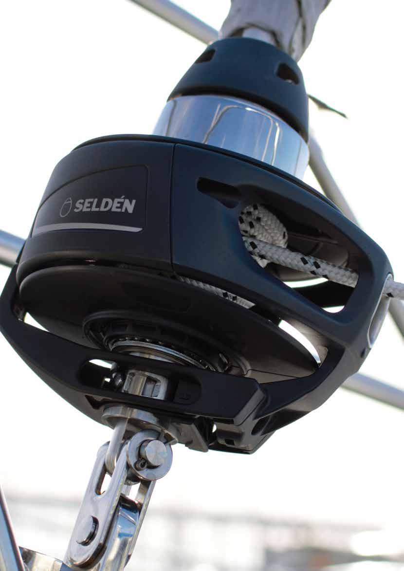
95
96 Toggles ye/fork toggle D 1 H H D 1 H 1 D 2 2 D 2 D 2 Can be used to lengthen a Furlex system. Fit it underneath the standard fork/fork toggle or at the top end of the Furlex wire. tandard Furlex fork/fork toggle T/fork toggle 2 Needed to connect the Furlex to a eldén backing plate for T-terminals. 2 Forestay dia., ength H Ø Clevis pin D 2 Fork width 2 Ø ye D 1 For rigging screw diam /4" 3, /1" /8" /1" /2" /8" /4" /4" /8" /8" /8" /8" M24 Forestay ength H Ø Clevis pin Ø Clevis pin Fork width Fork width dia., D 1 D Forestay dia., ength H Ø Clevis pin D 2 Fork width temball/eye toggle with fork/fork toggle D 1 1 D 1 HB H R H D 2 2 D 2 2 Needed when fitting Furlex to some masts of other origin than eldén. ye/fork extension link* Forestay dia., ength H Ø Clevis pin D 2 Fork width 2 Height HB Radius R Ø temball D Forestay dia., ength H Ø Clevis pin D 1 Fork width 1 Ø ye D 2 Gauge * If the boat is fitted with a bow anchor, it may be necessary to permanently raise the lower bearing assembly for anchor clearance. A selection of extension links are available. If the lower bearing assembly is raised by means of an extension link, a Furlex fork/fork toggle, should be fitted between the link and the forestay attachment. This in order to secure proper articulation in all directions. 9
97 Furlex with rod forestay Bush packs and join sleeve kits Bush packs for Navtec, BI and OY rods are available from eldén. Your rod rig manufacturer will supply the rod forestay and upper terminal parts, slide on rod bushing and hole screw, and form your rod heads. In some cases, the rod rig manufacturer also needs to slide on the join sleeves before forming the rod heads. Bush packs include a bushing and a hole screw. Always needed for rod installation. Join sleeve kits are only needed for some combinations. Rod Diameter Type of Furlex Bush pack Join sleeve kit Navtec Navtec Hole screw Navtec / Navtec Navtec Navtec Navtec Rod bushing OY R OY R OY R OY R OY R OY R OY R BI BI BI / BI / BI BI BI BI All Furlex systems include slotted distance tubes to be snapped on to the headed rod. For more information on installations of Furlex for rod forestay, see instruction of assembly , www. seldenmast.com. 97


98 Furlex TD (Through-Deck) Maximize your luff length and gain performance by a through deck installation. The free turn of the tack swivel is the same as in all other Furlex models. The tack fitting, however, is fixed to the deck. This gives you a more efficient trim of the sail. More space on the foredeck will be an extra bonus! Terminal for rod or wire The Furlex TD is designed for mounting through the deck. A torque tube with gimbal joint allows for full toggle articulation of the forestay. ith the Furlex TD you avoid having lots of water splashing into your anchor well. The very small amount of water that seeps through is easily handled by a normal drainage. Fork/fork toggle Torque tube with gimbal joint The Furlex TD is designed for installation on a wide range of yachts. The fork under the drum is extendable to reach down to the forestay attachment below deck. Tack ring Through-Deck fitting Deck bearing 10 extension (200TD/300TD) 190 extension (400TD) 98


 200TD 290-40 10 182 14 ( and 7) 14 ( and 7) 20 130 10 A 1 (8) 1 (8) 300TD 330-490 170 214 20 (8 and 10) 1 (8")
99 G F H Type Forestay Max forestay dimension, length (m)* 200TD TD TD B Type A B C D,, F G H (forestay (forestay max. dia., ) dia., ) 200TD ( and 7) 14 ( and 7) A 1 (8) 1 (8) 300TD (8 and 10) 1 (8 and 10) TD (12 and 14) 20 (12 and 14) C D * From deck to attachment in mast. 99
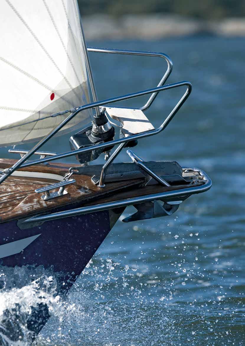
100


101 Furlex /TD (lectric) All the power you need The new Furlex lectric is available as a complete kit or as an upgrade kit for an existing Furlex 200, 300 or 400 series. The push-button performance of a Furlex lectric makes pulling on the furling line a thing of the past. Reliable function Furlex lectric is designed around a highly efficient 12V or 24V electric motor. Power is transmitted to a selflocking worm gear to rotate the luff extrusion at a max torque of 0Nm (200), 90Nm (300) and 13 Nm (400) respectively. These high torque levels mean that you can always rely on being able to furl your foresail even when the wind and sea are doing their worst. The motor uses only 30 amps at normal load and it takes 2-30 seconds to furl a genoa. Once the required sail area is set, the worm drive provides a mechanical lock. In order to prevent accidental overloading, the system comes with a built-in circuit breaker. If you attempt to reef the sail without first releasing the sheet, the power is iediately switched off. This safety feature is automatically re-set a few seconds after the control switch is released. In the event of power failure, the sail is simple to reef manually. An emergency line-driver system is included as standard and can be used for both on-deck and through-deck installations. An emergency handle with ½" socket is available as an option. On-deck or through-deck. The choice is yours Furlex lectric is available for either on-deck or throughdeck installations. The main advantage of a throughdeck installation is better sailing performance as a result of maxi mised luff length. More space on the foredeck is an added bonus! ike all other Furlex models, Furlex lectric is equipped with eldén s unique load distributor in the halyard swivel for low friction. ow friction means low power consumption and long service life. Installation of a Furlex 200TD. The connection box is water-tight. 101


102 Upgrade your manual Furlex ( ) Push-button performance is an easy upgrade for anyone who already has a manual Furlex 200, 300 or 400 series on their yacht. The furling line, drum and line guard assembly are simply replaced with a Furlex lectric motor unit. No sail conversion is required as the luff length of your existing sail is unaffected. Manual Furlex 200. Remove line guard, line guide, rope and drum halves. Ready to get powered up. lide on Furlex 200 from below and install the cables. Done! In case of power failure, Furlex lectric can be operated manually. Manufactured from highgrade materials for rugged reliability and long service life. Adjustment screws enable the Furlex housing to be aligned precisely. Heavy-duty toggle to withstand torsional loads. An extension link is available to provide anchor clearance. 102
103 Furlex lectric specifications Type Forestay diameter H3 H 2 D2 diam. H D2 H2 H H Type Forestay diameter Max. forestay length, m tandard version Furlex lectric assemblies (excl. control pack) Incl. rigging screw TD version (Through-Deck) Control pack* 12V 24V 12V 24V 12V 24V 12V 24V Cables & fuses included: Furlex connection box. Control box switches. Control box control panel. Fuse for control circuit in control box. Cables & fuses not included: Connection box control box. Control box battery. Fuse for power supply. * Includes deck gland, control box, connection box, instructions and switches. Control pack is ordered separately, often prior to the delivery of the Furlex lectric assembly. Optional items Remote control, receiver card included Type Forestay diameter Retro-fit installation kit incl. control pack Type Type TD TD 12V 24V 12V 24V Remote control, receiver card excluded Additional receiver card function upgrade kit tainless steel panel for switches (100 x x mergency handle (1/2" socket) Ø /7 eye/fork extension link, = Ø 8/10 eye/fork extension link, = Ø 12 eye/fork extension link, = Ø 14 eye/fork extension link, = Belt replacement kit Furlex Belt replacement kit Furlex Belt replacement kit Furlex For further technical information, please see our instructions for installation, 103


104 atch our furlers in action! eldén CX For Code 0 eldén GX For asyetric spinnakers 104

105 DÉN CX AND GX Furling systems for Code 0 and asyetric spinnakers ail definitions 10 The furlers 107 Accessories

106 D N A B A T R O O N 0 3 G G D D N B A T R O A A N 0 3 G G D D B A T R O N A A B A T R O N 0 3 G G D D R O B A T A A A BB AA T T R O N 0 3 G G D D N B A T R O R O N 0 3 G G D O R T A B 0 3 D N A A A B A T R O N 0 3 G G D R O 0 3 D N B A T A A B A T R O N 0 3 G G D B A T R O 0 3 D A A B A T R O N 0 3 G G D O R T A B B 0 3 D N A A A A B B AA A T T RR R OO O N 0 3 G G D D N R O A T B A T R O N 0 3 G G D D B A T R O N A A A A N 0 3 G G D D O O O R R R T T T A A A B N 0 3 G G D 0 3 D N A A B A T R O N 0 3 G G D 0 3 D N A A A A B A TT R R OO O G G D 0 3 D N N 0 3 G G D O O R T A A B B 0 3 D A A N 0 3 G G D 0 3 D N A A B A T R O N 0 3 G G D B A T R O 0 3 D N A A B A T R O N 0 3 G G D B A T R O 0 3 D N A A B A T R O N 0 3 G G D D B A T R O A A B A T R O N 0 3 G G DD D N O O O O R R R R R T T T A A A B B B A A A A B A A TT R R OO O N 0 3 G G D N G G D D N A A A A N 0 3 G G D D N A A B A T R O G G D D N B A T R O N 0 3 G G D D N B A T R O A A A B A T R O G G D D N B A T R O A B A T R O N 0 3 G G D D N B A T R O A A B A T R O N 0 3 G G D D N B A T R O A A A BB AA T TT RR R OO O N 0 3 G G D D B A T R O N N 0 3 G G D D B A T R O N A A A A N 0 3 G G D D B A T R O A B A T R O N 0 3 G G D B A T R O 0 3 D N A A B A T R O N 0 3 G G D B A T R O 0 3 D N A A B A T R O G G D D N B A T R O A A B A T R O N 0 3 G G D D N B A T R O A A A B A T R O N 0 3 G G D D N B A T R O A BB A A T R OO N 0 3 G G D B A T R O 0 3 D N A A G G D B A T R O 0 3 D N A A B A T R O N 0 3 GG G D B A T R O 0 3 D N A A B A T R O N 0 3 G DD B A T R O 0 3 D A A B A T R O N 0 3 G G G B A T R O 0 3 D N A A BB A A T R OO G D O R R T T A A B B 0 3 D A A A G GG G DD D B A T R O 0 3 D N A B B A T T R R OO G 3 0 D N A A 1-4 N D G B A T R O A A B A T R O - 4 G D N A B A T R O G eldén CX and GX ant to see your crew smile? The power and acceleration achieved when unfurling a Code 0 or an asyetric spinnaker is spectacular. It will make your sailing more fun. imply hoist the furled sail, release the furling line, pull on the sheet and you have added horse power to your sailing and given your crew a positive sailing experience. To douse the sail, ease the sheet, pull the continuous furling line and secure it in the purpose made Twin Cam block. Once the sail is furled it can be neatly dropped and coiled into a bag or left hoisted for later use. eldén provide all necessary accessories for safe and carefree furling of off-the-wind sails. The sails Code 0 The Volvo Ocean Race was the break through for the Code 0 concept, but lately the benefits of this type of sail have become recognized and appreciated also amongst ordinary sailors for the extra power it brings to light wind sailing. The luff is straight, set under tension and made for furling which simplifies the handling of this large sail. An AT-cable is integrated in the luff and fitted with thimbles in head and tack, and the entire luff length is furled simultaneously. The Code 0 is hoisted as high as the mast dimension permits and is tacked to the bow or to a sturdy bowsprit. The design is quite flat and reaches its maximum performance in apparent wind angles between 40 and 90. eldén CX is the right furler for this sail. Mid girth <7% of foot length 90 traight luff Asyetric spinnaker This sail is often called gennaker or cruising chute. The mid girth is >7% of the foot length and the sail is defined as a spinnaker in most international measurement rules. The luff is at least 2% longer than the leech and this is what makes the sail asyetric. This sail is furled with a eldén GX system and fitted at the tack to the swiveling tack attachment and at the head to the halyard swivel. An AT-cable connects the drum and the halyard swivel and transmits the rotation of the drum enabling the furling to start at the top and work its way down until the entire sail is stowed away. This is called top-down furling. The eldén GX furler is fitted to the bow of the boat or preferably on a retractable eldén bow sprit to expose the sail to the wind and to get clearance from the forestay. The halyard tension is moderate and the sail is hoisted using the spinnaker halyard. This sail performs at its best in apparent wind angles between 70 and 110. Mid girth >7% of foot length Positive curve in the luff 10


107 The furlers eldén CX and eldén GX are operated with an endless furling line running over a line driver drum. The furling line is preferably led all the way back to the cock pit and eldén offer the Double Fairlead and the Twin-Cam block for a well organized set up. A purpose made ATcable has been developed to secure the function of the system and as the performance of top-down furling is dependant on the torsional rigidity of the AT-cable, it is included in the eldén GX furlers. Metal teeth in the drum make for a good grip on the line when furling the sail. A wedge in the line guide separates the line from the drum when unfurling the sail and the drum spins freely. ealed steel bearing in the drum and in the halyard swivel for long service life. Rubber fender prevents the halyard swivel from chafing the mast while hoisting the furled sail. CX. pring loaded lock makes it easy to connect the thimbles to the drum and the halyard swivel. GX. Patented line lock for easy mounting of the AT-cable to the drum and to the halyard swivel. All structural parts are made of high-strength Duplex stainless steel. This means reduced material and low weight. Non-structural parts are made of impact resistant glass fibre reinforced polyamide composite. eldén GX, for top-down furling of an asyetric spinnaker/gennaker eldén GX drum and halyard swivel and an AT-cable is included in the kit. The drum and the halyard swivel are permantly fitted to the sail with the eldén line lock. Connect the drum to the bow and the spinnaker halyard to the halyard swivel. ead the furling line to the cockpit by using eldén Double Fairleads on the stanchions, tighten the furling line and secure it in the Twin-Cam block. Thereafter hoist the furled sail. eldén GX Kit including GX drum, halyard swivel and AT-Cable Q++ Max length of the system Drum size, Ø Dimension of included AT-cable, Ø Max suggested sail area m 2 Max working load, kn GX GX GX GX Q 107


108 elden CX, for Code 0 The AT-cable is integrated in the luff of the sail and thimbles connect the luff to the drum and to the halyard swivel. pecial cable clamps are required to fit the thimbles to the eldén AT-cable. A dedicated halyard for Code 0 is required and 2:1 purchase is recoended to obtain the required luff tension and to reduce the load on the halyard sheave and on the line stoppers. The drum and the furling line can be permanently mounted to the bow and along the stanchions. Q eldén CX Kit including drum and halyard swivel Q+ Drum size, Ø afe working load, kn Max suggested sail area, m 2 Max RM at 30 heel, knm Approx. displacement, tonnes CX CX ,7 CX CX AT-cable Cable clamp ine drum Thimble A eldén CX1 Code 0 furler and a Race80 Bowsprit from Båtsystem, weden. The luff load on a Code 0 is more than the double compared to an asyetric spinnaker. Therefore, a sturdy bowsprit is required. 108


109 eldén CX, for top-down furling of an asyetric spinnaker/gennaker This is an alternative to GX allowing the drum and the furling line to be mounted permanently. nap in the furled gennaker and hoist it using the spinnaker/gennaker halyard. A eldén CX drum is combined with a Free Tack Adapter and a GX halyard swivel, both of them with eldén line lock. The furled sail with the Adapter is connected to the drum and the sail is hoisted with the spinnaker hal-yard. The drum and the furling line can be permanently mounted to the bow and along the stanchions. Q eldén CX CX drum Kit including Free Tack Adapter & GX halyard swivel Q+ AT-cable Dimension, Ø This combination equals Max suggested sail area, m 2 CX GX7. 0 CX GX10 80 CX GX1 11 CX GX2 200 eldén CX, for Code 0 & top-down furling of an asyetric spinnaker/gennaker This is an all-in-one solution for the sailor using both Code 0 and gennaker and prefers using one halyard for both applications. A eldén CX drum and halyard swivel for thimbles are used both for the Code 0 sail and an additional gennaker. Connect the sail suitable for the prevailing conditions to the drum and to the halyard swivel and hoist the furled sail using the Code 0 halyard. The Free Tack Adapter is permanently fitted to the tack of the asyetric spinnaker/ gennaker with the eldén line lock. The drum and the furling line can be permanently mounted to the bow and along the stanchions. Q eldén CX CX drum and halyard swivel Q+ Adapter AT-cable Dimension, Ø This combination equals Max suggested sail area of the gennaker, m 2 CX GX7. 0 CX GX10 80 CX GX1 11 CX GX


110 Accessories eldén AT-cables (Anti-Torsion) The more torsional rigid AT-cable, the quicker and safer the sail will furl. eldén provide the most rigid cable on the market, three times more rigid than the second best, and it is included in the eldén GX kit. Unique and patented line lock system ength, Dimension, Ø To be used for... ine terminal with a conical shape. et of wedges CX10 CX1 GX7, CX10 + GX7, adapter CX2 GX10 CX1 + GX10 adapter GX1 CX2 + GX1 adapter Pull the terminal over the line and fold the core of the line over the wedges. Insert the wedges to the terminal CX4 GX2 CX4 + GX2 adapter Install the drum/halyard swivel and tighten the locking screw. ndless furling line ine only ine with Twin cam block installed ength, 2 x x x x Dimension, Ø 8 CX10 CX1 GX7, GX10 To be used for x x x x x x x x x CX2 GX1 12 CX4 GX2 Twin cam block for furling line PBB R (max Ø10 line) PBB R (Ø12 line) 110


 For")
111 Double Fairlead Ordinary blocks cannot be used to lead the endless furling line back to the cockpit. eldén Double Fairlead consist of a composite bracket fitted to a 2 or 30 stanchion and a spring loaded push-and-twist bracket in stainless steel. asy to open to attach the line and just as easy to close. The Double Fairlead prevents the line to get tangled up and the smooth stainless bracket prevents friction R. Code 0 halyard with 2:1 purchase To boost the performance when using a Code 0, the halyard load must be higher than what normal halyard boxes and stoppers can handle. Therefore, a 2:1 purchase needs to be arranged by fixing the dead end of the halyard in the mast and letting it run through a block attached to the halyard swivel. Position on the mast must be specified by eldén. In most cases Code 0 sails need to be hoisted lower than gennakers and spinn-akers. Block for 2:1 purchase Dim. eight, g 1 2 D afe working load, kg Breaking load, kg Max line size, R CX1 To be used for... 2 D R CX2, GX R CX4 1 Dead end fitting Mast section Max rope, Ø Max RM at 30º heel, knm R C1-F R C24-F R C321-F Thimbles for AT-cable (2 pcs) For AT-Cable, Ø To be used for CX10, CX CX10, CX CX CX CX4 Cable clamps To fit thimbles to the eldén AT-cable. Heat shrink tubing included. (2 pcs) For AT-Cable, Ø For CX2 and CX4 double clamps at each end of the AT-cable are required. 111


112 Adapters An adapter adds a tack swivel to a CX furler. The CX drum can now be used both for Code 0 and for asyetric spinnaker/gennaker. The adapters feature the patented eldén line lock and Torlon ball bearings. Anti-Twist shackle The Anti-Twist shackle is an optional shackle connecting the halyard to the halyard swivel. The long pin will lean against the mast and prevent a soft halyard from twisting. This shackle is not necessary for a 2:1 halyard set up nor is it for a high quality Dyneema halyard. Converts......to CX10 GX CX1 GX CX2 GX CX4 GX 2 Dimension To be used for R M, = 220 CX10, GX7., GX R M8, = 220 CX1, GX R M10, = 280 CX2, GX R M12, = 390 CX4 ow friction shackle This snap shackel has a big, well rounded loop allowing the rope to slide with low friction and it can be used to tension a eldén CX with 2:1 purchase. This not only makes for better performance but it also makes it easier to connect the eldén CX to a bowsprit, from the foredeck. The shackle is made of high strength Duplex steel and has a quality mirror finish. Dimension eight, g afe working load, kg Breaking load, kg To be used for R CX10, GX7,, GX R CX1, GX R CX2, GX R CX4 112


113 Adjustable Tack wivel (AT) This accessory for eldén GX furlers enables the sailor to easily trim the luff of the asyetric spinnaker/gennaker. The Adjustable Tack wivel slides up and down over the AT-cable and is handled from the cockpit with a down haul. As opposed to triing the luff by slacking the halyard, the AT-cable can now be permanently tensioned and always ready for furling. To be used for GX GX GX GX2 The sliding sleeve of AT consists of two halves and therefore it is easy to retrofit the swivel to a GX furler. 113

114 BYT bild Hydraulics are used for efficient trim of the sails and for pure convenience. 114

115 Hydraulics Mast jack system 11 The hydraulic set up 118 Furlex Hydraulic 122 Hydraulic cylinders


116 Mast jack system A mast jack from eldén ensures that you always retain the right rig tension for racing. It also lets you relieve the load on the rig and boat when you are in port. The mast jack system consists of a hydraulic cylinder located inside the mast. The cylinder piston moves down vertically through the heel of the mast to a steel plate in the boat s T-base, thereby lifting the mast and increasing the tension. In order to make it easier to jack up the mast, the system includes a two-stage pump that switches to its lower gear as the pressure increases. hen the mast reaches its upper position, shims are placed between the heel and the T-base. Release the pressure and remove the pump. Now, the rig is set in accordance with the predetermined require ments. o is the boom height, I-measurement and other rating measurements recorded by the measuring official. The pump is connected to the cylinder with stainless steel couplings, and can easily be disconnected and left ashore prior to racing. The hydraulic hose is then stored in a purpose-designed hose garage to keep it out of the way. The hose garage itself is fitted inside the mast. The T-base has the same pattern of holes as eldén s standard T-base, and its position can be adjusted in fore and aft direction to obtain the optimal mast rake. The hose is stored in a hose garage......and can easily be fitted to the pump to adjust the rig tension. 11
117 Hose garage inside the mast Tie rod prevents the deck from lifting when using the mast jack Heel Pump T-base Technical specifications ystem Mast extrusion D/300 C193 CC192 D3/400 C211-C24 CC210-CC244 D80/400 C24-C304 CC23-CC303 Max pressure (bar) Max working load (kn) Tie rod kit, includes conversion parts for standard deck ring Accessories Mast extrusion C193, CC C211, C227, CC210, CC22 C24, CC Hose garage, including pop rivets Guide rods Mast jack cylinder fitted on mast heel and 2-metre hose with quick coupling (male) Mast extr. Mast extr. Art. no Aluminium Carbon C CC C CC C CC C CC C CC C CC C CC Pump with manometer ystem T-base with shims and U-bolts for attaching tie rod D/ D3/ D80/ ystem (dim., ) D/ (20x140x1) D3/ (300x12x1) D80/ (370x10x2) him, 2 (D/300) him, (D/300) him, 10 (D/300) him, 2 (D3/400) (Optional) him, (D3/400) him, 10 (D3/400) him, 1 (D3/400) him, 2 (D80/400) (Optional) him, (D80/400) him, 10 (D80/400) him, 20 (D80/400) ocking bolts for shims (D/300) ocking bolts for shims (D3/400) ocking bolts for shims (D80/400) /4" hydraulic hose, 2 metres, with couplings Quick coupling (male) 40-9 Protective plastic cover for Quick coupling (female) Protective plastic cover for ealing washer for coupling U-bolt for securing tie rod ilicone spray, 20 ml, for rubber wedges for deck ring afety wire with Talurit eye. ome racing rules stipulate safety wire between mast and T-base. U-bolt for tie rod hims

118 Hydraulic cruise control eldén s hydraulic furling system for mainsail and foresail are: Furlex Hydraulic for headsails Hydraulic furling mast The picture to the right shows the principle of a hydraulic system with hyd raulic pump, valve units and drive units, all connected by hydraulic hosing. The system is operated from the cockpit by control switches connected to the system through a control box. Hydraulic outhaul 118

119 Boom outhaul Furlex 2 Furlex Control buttons 2. Control box 3. Pump unit, furling mast + Furlex 4. Pump unit, outhaul. Valve unit, furling mast + Furlex. Valve unit, outhaul 7. Filter Deck gland, furling mast + Furlex 9. Deck gland, outhaul 10. Battery
120


121 ångedrag 01 equipped with eldén hydraulic furling mast, hydraulic outhaul and double hydraulic Furlex jib-reefing systems. ailing from the cockpit at the press of a button A powered furling mast enables you to reef, furl and trim the sail area to suit the wind conditions at the touch of a button. The patented, built-in motor has a direct drive to the worm gear, to keep moving parts to a minimum and increase power, efficiency and reliability. The worm gear, which is self-braking, locks the sail in the required position. In an emergency, the mainsail can also be manually furled and unfurled with an ordinary winch handle. Hydraulic clew outhaul the ultimate control The push-button controls in the cockpit give you complete coand of your mainsail. You can also trim the outhaul when sailing close hauled a task which would ordinarily require the full strength of a crew member using a manual winch. Furthermore, there is no clew outhaul line to clutter up the cockpit. Booms available for hydraulic outhaul. B200, B20, B290 and B380 pecifications of hydraulic motors Model Motor Max. torque Nominal speed Nominal Nominal oil Max. oil Rec. min. power Max. sail designation at max. luff extrusion oil flow pressure pressure hydraulic pack area m 2 pressure, Nm (n), rpm (Q), l/min (p), bar (p), bar (P) k Type RB OM Type RC OM Type RD OM Type RD OM Type RD Built-in OM


122 Furlex H (Hydraulic) ith a Furlex Hydraulic, the cruise control is complete. All you need to do is press a button in the cockpit and adjust the sheet. The Furlex Hydraulic is designed to provide a har monious visual interplay of stainless steel and aluminium. The hydraulic motor is located inside the worm gear, in the same way as it is with the furling mast system. The positioning of the motor contributes to the compact design of the Furlex Hydraulic. Type Forestay dia., Max. forestay length, m Motor designation 300H 8 1. OM H OM OM OM OM H OMM rod rod rod Furlex Hydraulic, deck gland and deck gland protection. Furlex Hydraulic, deck gland and deck gland protection. 122
123 Max. width: Furlex 300H, 400H = 170 Furlex 00H = 184 F Hydraulic hose Quick fit connection D 1 G Deck gland uff groove pace for luff tape Furlex Hydraulic specifications Type Total weight uff extrusion Halyard xtrusion uff groove Max space for Max. luff tape Cut-Back drive unit, kg kg/m swivel, kg dim., luff tape, dia., dia., 300H x H x H x Type Forestay Rod Nav- OY* BI Max RM (knm) Clevis G F Forestay wire dia. tec (Riggarna) at 30 heel dia., adjustdia., Masthead Fractional ment 300H 8-12 (7.1) X X (7.) X X (8.4) X X (9.) X X X 400H (11.1) X X X (11.1) X (12.7) X X X 00H (12.7) X X (14.3) X X X (1.8) X X X * The upper eye terminal must be of the MNY type. Type Motor Max. torque Nominal speed Nominal Nominal oil Max. oil Rec. min. power Max. sail designation at max. luff extrusion oil flow pressure pressure hydraulic, pack area m 2 pressure, Nm (n), rpm (Q), l/min (p), bar (p), bar (P) k 300H OM H OM H OM H OM


124 Hydraulic cylinders Hydraulic adjusters and vangs Fast and convenient adjustment of the backstay and the vang is vital both for the racing sailor and for the cruising sailor. Being able to tension the forestay, adjust the pre-bend of the mast and control the power in the mainsail will make any boat point higher, sail faster and under better control. eldén has developed a range of hydraulic cylinders based on functional design, ease of use, reliability and long service life. The rods are marine grade stainless steel and the cylinders black anodized or clear anodized aluminium. The tensioners have long stroke making it possible to try out different mast rakes. Hydraulic Tensioners Integral (HTI) Hydraulic Tensioners (HT) for eldén control panels A 2-speed function permits fast tensioning until a pre-set pressure is obtained. Then the tensioner shifts down to low speed and reduced resistance in the handle. The level of pressure needed to gear down is easily adjusted to suit the individual trier. Available for Ø8 14 backstay wires (equals -17 to -40 rod). HTI: The gauge is at the top of the tensioner making it easy to check the achieved pressure (bar). Releasing the pressure is done by twisting the control of the release valve. An adjustable relief valve prevents overload. Maximum pump pressure adjustment. Pressure release valve. Adjustment of pressure level for downshift from high to low speed. Hydraulic Tensioners Integral (HTI) Hydraulic Tensioners (HT) for eldén control panels 124


 19 Hydraulic boom vangs (HV) Description Anodization Max pulling")

125 Hydraulic Backstay Tensioners Tensioner Anodization Max wire size, Ø (rod size) HTI-8/10 Clear 10 (-17) ,8 2 UNF Backstay tensioner with / integral pump Black eft hand Max pulling force at 000 psi, kn Max working pressure, bar troke, Contracted length, ower pin diameter, Ø Cylinder dia, Ø Piston rod thread eight, kg 2-speed function Dual Action 8,1 Yes No HT-8/10 Clear 82 4,3 Yes Backstay adjuster for pump station Black HTI-12/14 Clear 14 (-40) UNF Backstay adjuster, 7/ integral pump Black eft hand 13 No HT-12/14 Clear Yes Backstay adjuster for pump station Black Upper terminals Tensioner Fork Upper pin diameter, Ø HTI-8/10 HT-8/10 HTI-12/14 HT-12/14 Rigging screw body and split pin Anodization Clear ,8 / Black Clear / (for -22 rod) 19 Black (for -22 rod) 19 Toggle Tensioner ower pin diameter, Ø HTI-8/10 HT-8/10 HTI-12/14 HT-12/ , (for -22 rod) 19 Hydraulic boom vangs (HV) Description Anodization Max pulling force at 000 psi, kn Max working pressure, bar Maximum return force, kn troke, PCC (Pin Center ength Closed), HV-2 Clear ,4 Yes Yes Boom vang Black Pin diameter, Ø Cylinder dia, Ø HV-44 Clear 44,2 8, , Boom vang Black eight, kg HV-7 Clear, , Boom vang Black 2-speed function Dual Action 12


126 Control panels Available for single function or 4-functions. The panels have a Dual Action function which means the pump is active both when pushing and when pulling the handle. An adjustable relief valve prevents overload. A 2-speed function permits fast tensioning until a pre-set pressure is obtained. Then the panel shifts down to low speed and reduced resistance in the handle. The level of pressure needed to gear down is easily adjusted to suit the individual trier. The panels are black anodized or clear anodized aluminium. Pump station, 1-function Control panels Number of functions Anodization 2-speed function Dual Action Clear Yes Yes Black Clear Black Pump station, 4-function Pump handle, stainless steel, Ø20 x 00 Oil reservoir,


127 First 40 featuring a HT-8/10 tensioner and control panels both sides in the cockpit. HV-7 hydraulic boom vang.

128 128 The exhilarator Once you have experienced the thrill of the wind filling the spin naker, you are sure to be hooked on spinnaker sailing. eldén brings this sensa tion to yachtsmen all over the world through its com plete range of easy-touse alumi nium and carbon spin n aker poles and acces sories.

129 PINNAKR & GNNAKR poles and accessories Aluminium spinnaker poles 130 Telescopic poles 132 Jockey poles 132 etting a spinnaker 133 Carbon spinnaker poles 134 electing the right pole 13 pinnaker pole kits 140 pinnaker halyard attachments 142 pinnaker pole attachments 143 pinnaker pole fittings 14 pinnaker pole heel lift system 148 Vertical pole stowage 149 Gennaker bowsprit

130 Aluminium spinnaker poles eldén aluminium spinnaker poles give you fast and safe spinnaker handling. All the fittings have well-rounded edges to prevent personal injury and damage to equipment. The extrusions are lightweight and very durable, and are fitted with pole savers to shield the pole against damage from forestay and shrouds. Composite end fittings are available for our Ø 48-Ø 9 poles. These fittings are normally used for end-for-end gybing but can be used for vertical pole stowage and dip gybing as well. Our traditional aluminium fittings for dip gybing are available for the Ø 72-Ø 111 sections. Trip trigger All aluminium fittings and composite fittings for Ø 72-Ø 111 poles are available with a trip trigger function. You open the end fitting with a control line and the sheet locks it auto matically. This makes life easier for the foredeck crew. Four good ways There are four basic ways to handle the spinnaker. The end-for-end method, with the topping lift and down haul attached to the centre of the spinnaker pole, is most suitable for boats up to 2 feet in length. Another endfor-end method, with the topping lift at the centre of the pole and 130


131 mall composite end fitting with stainless chafe guard and Dyneema bridle for downhaul. Medium composite end fitting with stainless chafe guard, trip trigger and Dyneema bridle for downhaul. The aluminium extrusions are fitted with pole savers to shield the pole against damage from forestay and shrouds. the downhaul attached to the outboard end, is best for masthead rigged boats (max. 33 ft) and fractio n ally rigged boats (max. 40 ft). The third method, dip pole, is suitable for larger boats. The fourth way, twin pole arrangements, is recoended for yachts ranging from 40 feet and up - wards. Twin poles make it much easier and safer to gybe with the spinnaker on a big yacht. ection data X X Y Y Y ection I y I x all thick- eight dia., cm 4 cm 4 ness, kg/m 48/ / / / / / / x 3* Composite spinnaker pole fittings A lightweight composite fitting for fast and easy spinnaker handling. tainless, spring loaded plunger. These fittings can be used for end-for-end gybing as well as vertical pole stowage and dip gybing. pinnaker poles with composite fittings come with Dyneema-core bridles for topping lift and downhaul. Can be secured in place without removing the fittings from the tube, which also makes it easier to change or adjust the bridles. X * Only available with Harken end fittings. 131

132 hisker pole light conditions hisker pole heavy conditions Telescopic pole. Maximises your downwind performance. Minimises your stowage problem. pinnaker pole towage Telescopic poles Telescopic pole, can be extended to 10% of normal spinnaker pole length, a must when poling out a large genoa or a gennaker. It can be telescoped down for easier stowage. RM 30 knm Displ. tonnes ection dia., eight Min. length for stowage pinnaker pole postion hisker pole heavy conditions hisker pole light conditions Inner Outer kg Jockey pole pinnaker pole The jockey pole reduces the loads and mini mi ses the wear on guys and life lines. Jockey poles * includes inboard end and requires male fitting at the mast. RM ec- Total 30 tion length knm / / / / / / * 20 9/


133 Ready, set, go Hook up the spinnaker. et up the spinnaker pole, topping lift and downhaul. Adjust the pole to suitable sailing trim. Haul in the windward guy. Also, haul in the leeward sheet to prevent the sail from twisting. Hoist the spinnaker. It is a good idea if someone assists at the mast. et the halyard run through a closed rope stopper. That way, you will not lose it if it fills early. Make sure that the spinnaker runs free from the bag or through the forepeak hatch. Call out Top! when the spinnaker is fully hoisted. Adjust the guy and sheet. Tidy up and hand in the jib. hen taking down the spinnaker, release the halyard first, followed by the leeward sheet. Do not release the windward guy until the spinnaker is fully down. If you want to read more about spinnaker sailing please order our free brochure, Using a spinnaker,

134 Carbon spinnaker poles eldén quality e have developed our own computer controlled manufacturing method in which prepreg (pre-impregnated) tows are wound onto a mandrel (cylinder) prior to oven curing. This method enables us to exercise full control over every stage of the manufacturing process and guarantee products of consistently high quality. One of the big advantages of this eldén production method is that it enables us to achieve sufficient durability in the areas subject to the greatest loads and wear. In all sizes eldén carbon spinnaker poles are suitable for dinghies and for yachts up to 30 tonnes. The larger poles are tapered to optimise weight/strength requirements, and facilitate handling. 134
 with medium composite end fittings, trip trigger and Dyneema bridle.")

. Aluminium spinnaker pole ection 99/99, length 10, weight 1.9 kg.")

135 Carbon spinnaker poles (dimensions 47/47 and 9/9) with small composite end fittings and Dyneema bridle. Carbon spinnaker poles (dimensions 77/77 and 88/88) with medium composite end fittings, trip trigger and Dyneema bridle. Dip pole, trip trigger end fitting. Female casting for clip-on spigot. Harken end fitting for larger poles. eldén spinnaker poles are designed to make light work of spinnaker handling. The big advantage of carbon fibre is its low weight. The weight savings enable the crew to handle the spinnaker faster, with less effort. eight comparison aluminium and carbon spinnaker poles (equal strength). Aluminium spinnaker pole ection 99/99, length 10, weight 1.9 kg. Carbon spinnaker pole ection 102/102, length 10, weight 9 kg. eldén carbon spinnaker poles Type ection eight Inertia dia., kg/m Al-equivalent cm 4 Untapered tube Tapered tube Twaron protection can be supplied as an option. Twaron filaments protect the pole from damage caused by the forestay and shrouds. 13
. xample: For an aluminium spinnaker pole. Yacht displacement 8.0 tonnes, P is 100. The correct section is 99/99. Table terminology RM: Righting moment at 30 of heel.")
136 electing the right pole Just look in the appropriate table for your yacht s displacement or righting moment (RM) at 30 heel, then look right for the value exceeding your P or J value (shown in the sail plan). xample: For an aluminium spinnaker pole. Yacht displacement 8.0 tonnes, P is 100. The correct section is 99/99. Table terminology RM: Righting moment at 30 of heel. P (J): Maximum spinnaker pole length for your yacht. A whisker pole should be approximately as long as the foot of the sail you intend to pole out. Topping lift hen P is within 00 of a dimension shown in bold blue, a bridle topping lift is recoended if down haul is at outboard end of pole. For 99/99 and larger diameter poles, use outboard end lift only. Downhaul Poles should have downhaul attached via a bridle or at outboard end. If a central attachment is desired, the pole diameter must be increased to the next size up. Aluminium spinnaker pole selection max P () RM 30º knm Displ. tonnes 48/48 0/0 72/72* 84/84* 9/9 99/99 111/ / * Max available P with composite end fittings, attached to a fixed mast ring. If the pole is to be Dip Gybe, max available P is increased by 1. 13


137 Aluminium whisker pole selection max pole length () RM 30º knm Displ. tonnes 48/48 0/0 72/72 84/84 9/9 99/ Downhaul Poles should have the downhaul attached via a bridle or at the outboard end. If a central attachment is desired, the pole diameter must be increased to the next size up. 137
: Maximum spinnaker pole length for your yacht.")
138 Table terminology RM: Righting moment at 30 of heel. Topping lift/downhaul Central attachment points for lift and downhaul are not available. nd-for-end poles have optional bridles made from the core of spectra rope. Poles for dip gybe always use the outboard end attachments. P (J): Maximum spinnaker pole length for your yacht. A whisker pole should be approximately as long as the foot of the sail you intend to pole out. Carbon spinnaker pole selection max P () RM 30º knm Displ. tonnes 47/47 9/9 1/1 77/77 88/88* 90/90* 102/ / /137 1/1 18/ * * * * * 40* * 40* * 40* * Max available P with composite end fittings, attached to a fixed mast ring. If the pole is to be Dip Gybe, max available P is increased by. 138

139 Carbon whisker pole selection max pole length () RM 30º knm Displ. tonnes 47/47 9/9 1/1 77/77 88/88* 90/90* 102/ / /137 1/ * * * 40* * 40* 40* * 40* 40* * 40* 40* * 40* 40* * 40* 40* * 40* 40* * 40* 40* * 40* 40* * 40* 40* * 40* * * * * * Max available P with composite end fittings, attached to a fixed mast ring. If the pole is to be Dip Gybe, max available P is increased by. 139


140 pinnaker pole kits There is no need to wait for eldén to build your customized spinnaker pole. You can easily build it yourself from one of our kits. Your local eldén dealer will, of course, be happy to do the job for you. Aluminium spinnaker pole kits Fittings designed for: nd-for-end gybing, dip pole gybing and vertical pole stowage. ection, Max spinnaker Type of end fitting dia., pole length, of of 34-84* ** 9 20 * Trip trigger retrofit kit, ** Only to be used as a whisker pole. Aluminium spinnaker pole kits Fittings designed for: Dip pole gybing and vertical pole stowage. ection Max spinnaker Type of end fitting dia., pole length, * Outboard end Inboard end Outboard end Inboard end * Trip trigger retrofit kit,

141 Carbon spinnaker pole kits Fittings designed for: nd-for-end gybing, dip pole gybing and vertical pole stowage. ection Max spinnaker pole Type of end fitting dia., lenght, of of 34-84* Bridle kit Includes Ø4 HMP* rope and stainless steel ring. For max spinnaker pole lenght, * High modulus polyethene. xit box for trip line For dip pole gybing, the trip line must exit through an exit box. For further information, see instruction on Dimensions, x9 * Trip trigger retrofit kit, Carbon spinnaker pole kits Fittings designed for: Dip pole gybing and vertical pole stowage. ection Max spinnaker pole Type of end fitting dia., lenght, Inboard end, Outboard end, * * Trip trigger retrofit kit, Tools for working with carbon fibre Description Used for section, dia., Drill Ø 4, Drill Ø 4,8 47, 9, Drill Ø,4 77, 88, Hacksaw blade All arning: Always use breathing protection when drilling or cutting carbon products. Twaron protection Protects the pole from damage from the forestay, rail impact, etc. Two protectors needed for endfor-end poles. For One protector, Two protectors, section, for dip pole gybing, for end-for-end gybing


142 pinnaker halyard attachments Masthead rig or fractional. eldén offers a full range of single and double spinnaker halyard attachments. Mast section ingle fitting Dimensions Double fitting Dimensions Remarks oop Fits small mast sections Ø idth: 0 oop Ø idth: Bracket Bracket R190-R213 C1-C227 F17-F228 C24-C304 F24-F x x 100 Max. RM: 0 knm x 14 x Max. RM: 0 knm U-bolt 224, 237 R214, R232, R20 C1-C28 F17-F Ø 8 idth: 3 Max. RM: 100 knm 274 R290 C304 F30 Ø 12 idth: 70 Max. RM: 180 knm 321, 3 R290-R370 C28-C3 F324-F370 Ø 12 idth: 70 ith fitted lower washer Max. RM: 20 knm 142

143 pinnaker pole attachments eldén has the right attachment for all your needs dip pole or end-forend arrangement, RCB cars and slide cars, including cars for vertical pole stowage. Jockey poles, fixed eye Inner diameter 30 Mast section 1, 170, 177, , 224, 237, 274 D137, D14, D10 R190, R214, R213, R R232, R20, R290 All C-sections and F-sections pinnaker poles, fixed eye Inner diameter 30 Mast section P90, 122, C P100, P111, 130, D121, D129, 138, 1, D10, R190, R213, C17-C227, F17-F , 177, 189, 20, D14, R23, R232, R20, R290, C24-C304, F24-F , 237, F28-F Modify base to match front radius of section

144 pinnaker pole cars, RCB Type of car 1:1 purchase 2:1 purchase Track width pinnaker pole end fitting, Max. RM 10º car knm 10º car for vertical pole stowage mall Medium 120 knm 10º bayonet car knm 0 Ring car with eyes for lift and downhaul mall Medium 120 knm 30 10º bayonet knm 10º vertical pole stowage, double car with bayonet knm 0º standard double car with bayonet knm 10º vertical pole stowage, double car with bayonet knm 0º standard double car with bayonet knm 144

145 11-3 sp slider pinnaker pole sliders Type of slider Ring inner Track width pinnaker pole end Max. RM liding inserts dia., fitting, Ring slider with / knm locking device Ring slider knm with eyes for RCB knm lift and downhaul knm eps eps slider fore * 2 4 knm vertical pole stowage * 32 4 knm * RCB 30 7 knm ith bayonet knm ith bayonet 32 4 knm lider with ith bayonet 10 RCB 30 7 knm eyes for lift and downhaul. * These sliders include toggle , designed for our composite end fittings (page 14). 14


146 Composite spinnaker pole fitting, Composite spinnaker pole fitting, Inboard end fitting, for bayonet slider. Art. nr Outboard aluminium end fitting pinnaker pole fittings nd fitting Material Trip trigger Pole section Adaptor function mall Composite No 48/ / Medium No 72/ Yes No 84/ Yes No 9/ Yes Outboard Aluminium Yes 72/ / / / / Inboard / / / / / Jockey pole fitting, outboard end nd fitting Pole section Adaptor dia., Jockey pole fitting. mall Medium
147

148 pinnaker pole heel lift system The heel lift system provides effortless spinnaker hand ling and allows the crew to set the spinnaker in the perfect position. heave box A-4 Cheek block Tracks not included in the heel lifting system. ee page point eye Cheek block heave box A-4 Cheek block Fairlead Cam cleat lot fitting Cam cleat Ø 8 2-point eye Fairlead lot fitting inch, Andersen 10 ine tender Cleat inch pad Cleat Cheek block C17-F24, : Operation from cockpit. (cleat 11-01*). C227-F24, : (cleat *). C24-F30, : (cleat 11-01*). towage brackets *For more information about cleats, see page 48. C17-C24: C24:
149 Vertical pole stowage Mast section Track width 2, radius 34*, ** ength 1700, ength 3400, , 130 Vertical pole stowage D137, 138 1, D10 R190, R213 R23 C1-C24 F17-F2 nd-for-end slider for pole sections 48/48-9/9 Carbon 47/47 and 88/ Bayonet slider for pole sections 72/72 and 84/84 Carbon 77/77-118/ Track length nd-for-end spinnaker pole slider Ring slider with locking device pi-pole lift system, see page 148 oop + support * For yachts with an RM over 2 knm fit track with double pop rivets (Ø 4.8x12.7 ). 14 extra pop rivets/track. ** nd stops and pop rivets included. Mast section Track width 30, radius 38 ** Track incl. Ø.4x12.7 pop rivets: ength 2400, ength 3400, ength 4800, Track incl. Ø.4x17.8 pop rivets: ength 2400, ength 3400, ength 4800, Ø.4x12.7 pop rivets: 170 D14, D10 R213, R23 C193-C24 F194-F2 Ø.4x17.8 pop rivets: R232, R20 C28 F28 Ø.4x12.7 pop rivets: 177, , C321* C304* Ø.4x17.8 pop rivets: 274*, 3* R290*, F324* F30*, C3, F370* Track length Vertical pole stowage nd-for-end slider for pole sections 72/72-9/9 Carbon 77/77-88/ nd-for-end RCB spinnaker pole car for sections 72/72-9/9 Carbon 77/77-88/ pi-pole lift system, see page 148 oop + support Bayonet RCB spinnaker pole car for sections 72/72 and 111/111 Carbon 77/77-118/ nd-for-end spinnaker pole slider Ring slider with eyes for lift and downhaul RCB ring slider with eyes for lift and downhaul Track width 30, radius 4 ** Track incl. Ø.4x12.7 pop rivets: ength 2400, ength 3400, ength 4800, Track incl. Ø.4x17.8 pop rivets: ength 2400, ength 3400, ength 4800, Vertical pole stowage nd-for-end slider for pole sections 72/72-9/9 Carbon 77/77-88/ nd-for-end RCB spinnaker pole car for sections 72/72-9/9, 72/72-111/111 Carbon 77/77-88/ pi-pole lift system, see page 148 oop + support for C304/F30/C321/F324 Bayonet RCB spinnaker pole car for sections Carbon 77/77-118/ nd-for-end spinnaker pole slider Ring slider with eyes for lift and downhaul RCB ring slider with eyes for lift and downhaul Calculate track length: Min. = pinnaker Pole ength (P) minus 100. Max. = P minus 00. If the spinnaker pole track passes a P-spreader bracket, bedding must be used ( = 4000 ). Calculate length of pole heel lift rope: 2 x P + 2 metres. * Use stowage bracket or ** nd stops and pop rivets included. 149
150


 G072 Ø72/72 =< 2080 072-072-70 G07 Ø7/7 =< 2230 07-07-70 G087 Ø87/87 =< 2270 087-087-70 G099 Ø99/99 =< 310 099-099-70 GC07 Ø7/7 =< 3000 07-07-70 GC088 Ø88/88")
151 Gennaker bowsprit xtendable gennaker bowsprit sold as a kit for deck mounting. Just fit the two stainless steel pad eyes to the deck in line with the bow bracket. The bracket is a stain less ring with a low friction polyamide inner lining through which the bowsprit slides into its active position. After the gennaker is doused, the bowsprit can slide back and be secured to the aft eye. If required, it can be quickly removed and stowed securely below. The gennaker tackline runs through the bowsprit, entering and leaving via well rounded holes, and then aft to the cockpit. An alternative is to fit an external tack block at the outboard end. Gives the gennaker more clear air Facilitates rapid gybing Always ready for quick extension Makes for fast and efficient gennaker handling Improves performance when gennaker sailing Can be fitted to most yachts Available in carbon or aluminium Bowsprit kits The kit includes: Aluminium or carbon bowsprit section, inboard end fitting with plunger, outboard end fitting, 2 stainless steel pad eyes, instructions. Aluminium Carbon Description Dimension () G072 Ø72/72 =< G07 Ø7/7 =< G087 Ø87/87 =< G099 Ø99/99 =< GC07 Ø7/7 =< GC088 Ø88/88 =< GC089 Ø89/89 =< GC100 Ø100/100 =< GC101 Ø101/101 =< pring-loaded locking device for safe and easy handling. Bow bracket tainless steel bow bracket with PA inner lining. To be bolted to deck or rail. tainless steel bow ring with PA inner lining. Can be welded to bow anchor fitting or sturdy pulpit. tainless steel bow fitting with PA inner lining bushing. Can be integrated with some bow anchor fittings (e.g. Jeanneau). idth of base: 17. Fitted with Ø 12 bolt. 90 bracket and bow ring for assembly on bow anchor fitting. Bowsprit, diameter () Ø 72/ Ø 7/7 Ø 7/ Ø 87/87 Ø 88/88 Ø 89/ Ø 99/99 Ø 100/100 Ø 101/ Ø 72/ Ø 7/7 Ø 7/ Ø 87/87 Ø 88/88 Ø 89/ Ø 99/99 Ø 100/100 Ø 101/ Ø 72/ Ø 7/7 Ø 7/ Ø 87/87 Ø 88/88 Ø 89/ Ø 72/ Ø 7/7 Ø 7/ Ø 87/87 Ø 88/88 Ø 89/ Ø 99/99 Ø 100/100 Ø 101/ Bow fittings on some boats can be integrated with the bow anchor fitting. ide mounted installation on stem head anchor fitting 11

152 Dimensioning for gennaker, Aluminium RM 30º (knm) Approx. displ. (tonnes) Max U G072 G07 G087 G099 Min DB Max U Min DB Max U Min DB Max U Min DB ) ) ) ) ) ) ) ) ) ) ) ) ) DB = Distance between support. U = Unsupported length. Bold numbers mean min DB is limited by bowring capacity. If a custom bowring is used, the min DB is 8 x pole diameter. 1) No standard bow bracket is available. If a custom bowring is used, the min DB is 8 x pole diameter. Dimensioning for Code 0, Aluminium RM 30º (knm) Approx. displ. (tonnes) Max U G072 G07 G087 G099 Min DB Max U Min DB Max U Min DB Max U Min DB ) 10 1) 70 1) ) ) Bold numbers mean min DB is limited by bowring capacity. If a custom bowring is used, the min DB is 8 x pole diameter. 1) No standard bow bracket is available. If a custom bowring is used, the min DB is 8 x pole diameter. 12
153 Dimensioning for gennaker, Carbon RM 30º (knm) Approx. displ. (tonnes) Max U GC07 GC088 GC089 GC100 GC101 Min Max Min Max Min Max Min Max DB U DB U DB U DB U ) 930 1) ) 900 1) ) 870 1) ) 840 1) ) 810 1) ) 790 1) ) 770 1) ) 70 1) ) 730 1) ) 710 1) ) 90 1) ) 70 1) ) 0 1) ) ) ) ) Bold numbers mean min DB is limited by bowring capacity. If a custom bowring is used, the min DB is 8 x pole diameter. 1) No standard bow bracket is available. If a custom bowring is used, the min DB is 8 x pole diameter. Min DB Dimensioning for Code 0, Carbon RM 30º (knm) Approx. displ. (tonnes) Max U GC07 GC088 GC089 GC100 GC101 Min Max Min Max Min Max Min Max DB U DB U DB U DB U ) 840 1) ) 70 1) ) 80 1) ) 30 1) ) ) ) Bold numbers mean min DB is limited by bowring capacity. If a custom bowring is used, the min DB is 8 x pole diameter. 1) No standard bow bracket is available. If a custom bowring is used, the min DB is 8 x pole diameter. Min DB 13

154 14

155 IGHT Masthead lights 1 Floodlights and steaming lights 17 Retro-fitting cables 18 Cable conduits 18 Cables and dimensions 18 1


 <12 m (International) Anchor light 12V/24V Anchor and steamlight 12V For boats OA <7 m tainless housing + screws")
156 Compulsory lights International Regulations for Preventing Collisions at ea, 1972, stipulate compulsory lights on all yachts. eldén offers all the necessary lighting equipment to comply with the rules. Tricolour/white with or without anchor light. Anchor light Masthead lights, D Aquasignal 34 Anchor light/steaming light Aquasignal series /-002. teaming light Available in two versions, for yachts less than 12 m and for yachts between 12 m and 20 m. Available in black composite or in stainless steel Item Conditions Fitting Type of masthead Anchor light Tricolour lamp Anchor light and Tricolour lamp teaming light with anchor light For boats OA <0 m Visibility 2nm For boats OA <20 m Visibility 2nm For boats OA <20 m Visibility 2nm For boats OA <20 m Visibility 2nm Required cable Base 08-0 incl º Base 08-2 incl º Base 08-0 incl º Base 08-2 incl º Base 08-0 incl º Base 08-2 incl º Base 08-0 incl º Base 08-2 incl º Masthead lights Fig 1. Item Conditions Fitting Type of masthead Anchor light 12V For boats <7 m (candinavia) <12 m (International) Anchor light 12V/24V Anchor and steamlight 12V For boats OA <7 m tainless housing + screws MRT x10 For boats OA <12 m Required cable Base incl º Base 08-2 incl º /0 0º tainless housing, base 08-0 incl. tainless housing, base 08-2 incl. tainless housing, base 08-2 incl. tainless housing, base 08-0 incl /04 1º /0 0º º º index light 12V All No fasteners required ee fig index light 24V Fit below index base Tricolour lamp, For boats OA <20 m Base 08-0 incl /0 1º Quick fit. 12V/24V Base 08-2 incl /0 0º Tricolour lamp/hite, Base 08-0 incl /0 1º Quick fit. 12V/24V Base 08-2 incl /0 0º 1


 Base 2-01-01 31-003 <12 m (international) 08- incl.")
157 V-spreader integrated In-spreader lighting is a good solution for improving working light on board. The in-spreader light is available for eldén V-spreaders. Floodlight uits bigger mast sections. Completely protected against halyards and sails. ight guard, In-boom light The eldén in-boom light comes in handy to light the cockpit or as a guide light when going down below. The in-boom lights are available for new eldén boom section from 13/71 and upwards. Not available for retrofit. Floodlight and steaming lights Item Conditions Fitting Remarks Required cable Floodlight, 12V/3 All masts, front mounted Black housing * Pop rivets Floodlight, 24V/ * incl. Floodlight, 12V/3 hite housing * Floodlight, 24V/ * Floodlight, 12V/3 All masts, side mounted Black housing * Floodlight, 24V/ * Floodlight, 12V/3 hite housing * Floodlight, 24V/ * teaming lights, 12V/10 For boats OA <7 m (candinavia) Base <12 m (international) 08- incl. teaming lights, 12V/2 For boats OA <12 m (candinavia) Base crews teaming lights, 24V/2 <20 m (international) incl incl. teaming lights, 12V/2 For boats OA <20 m Protection loop Fasteners teaming lights, 24V/ incl incl. Protection loop, alum. For use with Aquasignal steaming lights (2 pcs) Protection loop, stainless 274, C304, F30 and bigger Nylon base for light. uits most lights and mast sections * ight insert: 12V ( 32-14), 28V ( 32-1). O-ring for floodlights

158 Retro-fitting cables For all D-sections, -sections, P-sections and R-sections, please see our instruction Running cables Also available from Cable conduits C211 C227 C24 C24 C28 C304 C1 C17 C F212 F228 F24 F2 F28 F Cables and dimensions F17 1 F194 ight ffect Cable Required cable length, m area, 2 24 Anchor light teaming lights and navigation lights Floodlight All eldén masts have a cable identification to facilitate connection when stepping the mast. 1. Top light 2. Navigation light 3. Anchor light 4. index. Flood light. Aerial 7. ind instrument Cable for: Cable Remarks area, 2 ind instrument 10 x Ø 7.3 index light, anchor 2 x Ø.9 light and steaming lights Tricolour/white/strobe 4 x Ø 8. Tricolour lamp, flood- 2 x Ø 7. light and steaming lights Tricolour lamp/white, 3 x Ø 8.1 anchor and steaming lights Aerial RG 213U ohm (min. for VHFradio according to German standard) Ø 10.2 (Cable terminal ) RG 8U ohm, Ø.4 (Cable terminal ) 18


159 Cable support Protects the cable from wear in the exit area. ead the cable out through a Ø 14 hole, jam the support onto the cable and plug the hole. Max cable size: 2 x 2. 2 (Ø 7. )

160 All our rig fittings are manu fac tured using the very latest in production technology, to achieve maximum durability and corrosion resistance. All product development work is carried out at eldén s own development department in weden. e retain complete control over every aspect of the whole design and manufacturing process. By doing this, we can guarantee quality, and ensure that you get the most out of your rig. 10

161 RIG FITTING Chrome bronze rigging screws 12 Backstay tensioners 18 Rigging screw covers 19 Hints 19 Fittings 170 Toggles 174 plit pin, split rings and clevis pin 17 heaves, bridles plates and insulators


 Internal fork width () Breaking load kn 174-321-01 1/4\" 13 199. 12. 7 1. 174-322-01 /1\" 1 238 8 1 8 24. 174-323-01 3/8\" 198 28 9. 18 10 34.")
162 Chrome bronze rigging screws Bronze, like stainless steel, is very strong and highly resistant to corrosion. By making the body of the rigging screw in chrome plated aluminium bronze and the terminals in high grade marine stainless steel, we have reduced the risk of the thread seizing up under heavy loads. A design feature which gives you a product that performs better and lasts even longer. All eldén rig screws are locked with split pins through the threaded terminals. A safe and proven method. Important note on /8" rigging screws Back in 1998 we changed the clevis pin diameter from Ø 13 to Ø 1.8. hen upgrading to new rigging screws on a boat built prior to this change, the clevis pin will most likely be bigger than the chain plate hole. The Ø 1.8 clevis pin has to be replaced by one Ø 13 pin and two bushings. Conversion kit, H Pin dia Chrome bronze rigging screws Fork + Fork Art. no. Thread size UNF Min. ength () Max. Clevis pin dia. Internal fork height (H) Internal fork width () Breaking load kn /4" /1" /8" /1" /2" /8" /4" /4" /8" /8" " "
163 Chrome bronze rigging screws Fork + tud terminal Art. no. Thread size UNF ire dia. Min. ength () Max. Clevis pin dia. Internal fork height (H) Internal fork width () Breaking load kn /4" /4" /1" /1" /8" /8" /1" /1" /2" /2" /8" /8" /4" /4" /4" /4" /8" /8" /8" /8" H Pin dia Chrome bronze rigging screws Toggle fork + Fork H1 Pin dia Art. no. Thread size UNF ength () Min. Max. Clevis pin dia. Toggel fork internal fork height, (H 2 ) Internal fork height, (H 1 ) Internal fork width () Breaking load kn /4" /1" /8" /1" /2" /8" /4" /4" /8" /8" Chrome bronze rigging screws Toggle fork + tud terminal H2 Art. no. Thread size UNF ire dia. Min. ength () Max. Clevis pin dia. Toggel fork internal fork height, (H) Internal fork width () Breaking load kn /4" /4" /1" /1" /8" /8" /1" /1" /2" /2" /8" /8" /4" /4" /4" /4" /8" /8" /8" /8" " " H Pin dia 13
164 Chrome bronze rigging screws Open + temball Thread size UNF Radius (R) Breaking load kn R /4" /4" /1" /1" /1" /8" /8" /1" /1" /2" /2" /8" 14 9 Chrome bronze rigging screws Fork + temball Thread size UNF Min. ength () Max. Clevis pin dia. Radius (R) Internal fork height (H) Internal fork width () Breaking load kn /4" /4" /1" /1" /1" /8" /8" /1" /1" /2" /2" /8" R Pin dia H Chrome bronze rigging screws temball + tud terminal Thread size UNF ire dia. Min. ength () Radius (R) Breaking load kn Max /4" /4" /4" /4" /1" /1" /1" /8" /8" /1" /1" /2" /2" /8" R 14
165 Chrome bronze rigging screws Open + tud terminal Thread size UNF ire dia. Breaking load kn /4" /4" /1" /1" /8" /8" /1" /1" /2" /2" /8" /8" /4" /4" /8" /8" Chrome bronze rigging screws ye + tud terminal Thread size UNF ire dia. Min. ength () Max. ye, Ø Breaking load kn /4" /4" /1" /1" /8" /8" /1" /1" /2" /2" /8" /8" /4" /4" /8" /8" ye dia 1
166 Chrome bronze rigging screws tud + T-terminal Thread size UNF ire dia. Min. ength () Max. Breaking load kn /1" /8" /1" Chrome bronze rigging screws Open + Toggle Thread size UNF Clevis pin, dia. Internal fork height (H) Internal fork width () Breaking load kn /4" /1" /8" /1" /2" /8" /4" /4" /8" /8" " H Pin dia Chrome bronze rigging screws Open + Fork Thread size UNF Clevis pin, dia. Toggel fork internal fork height, (H 2 ) Internal fork width () Breaking load kn /4" /1" /8" /1" /2" /8" /4" /4" /8" /8" H Pin dia Chrome bronze rigging screws Open + ye Thread size UNF ye, Ø Breaking load kn /1" /8" 1. 9 ye dia 1
167 Chrome bronze rigging screws ye + ye Thread size UNF Min. ength () Max. ye, Ø Breaking load kn /1" /8" ye dia H Pin dia Chrome bronze rigging screws Fork + T-terminal Thread size UNF Min. ength () Max. Clevis pin, dia. T dia. Breaking load kn /1" Rigging screw oil Volume ml All rigging screws should be lubricated every year. 17


168 Backstay adjuster, mechanical For hydraulic backstay adjusters, see page 124. eldén backstay tensioners have smooth, clean surfaces. ven the wire terminal is fully covered. These lowweight backstay tensioners are simple to use. All you do is insert a standard winch handle and turn. The tensioner has a maximum working load of 30 kn. The stroke is an ample 20 or 400, depending on the length of the tensioner. Clevis pins and bushes are supplied with every adjuster to suit small chainplates for Ø and Ø 7 wire. hen using the backstay adjuster with a Ø 10 backstay, the following limitations apply: forestay and backstay are both Ø 10, 1 x 19 wire or other stay material with an ultimate strength of 88 kn (8800 kg/19499 lbs) or less the backstay-to-mast angle must be at least 40% greater than the forestay-to-mast angle. Halyard tensioners. orks as a halyard tensioner too The backstay tensioner can also be used as genoa and main halyard tensioner, suitable for yachts up to feet. It is permanently fitted to the mast, and connects directly to the wire halyard. The halyard s detachable rope tail simplifies stowage. Backstay tensioners for Ø -8 wire troke Min/max Breaking afe working length, load, kn load, kn / / Halyard tensioners troke Min/max Breaking afe working length, load, kn load, kn /

 38/3 0 319-80 x 2 319-81-01 1/2\" (7 ) 43/40 0 319-81 x 2 319-82-01 /8\" (8 ) 0/4 700 319-82 x 2 319-83-01 3/4\" (10 ) 7/3 800 319-83 x 2")
 at the top of the backstay tensioner. The tape marker will enable you to avoid over tensioning. Intermediate values can be marked with different colours.")
.")
169 Rigging screw covers Aluminium rigging screw covers with PVC top-plug The round rigging screw covers are kind to your sails, sheets and clothing. Nothing can get snagged or chafed on the rigging screws. The rigging screws can be kept well greased, without having to worry about staining the sails or sheets. For Tube Tube pare rigging screw dia., length top plug outer/inner /1" ( ) 38/ x /2" (7 ) 43/ x /8" (8 ) 0/ x /4" (10 ) 7/ x /8" (12 ) 7/ x " (14-1 ) 87/ x 2 hen the backstay has been fully tightened, mark the stay with a piece of tape (see Fig. 1) at the top of the backstay tensioner. The tape marker will enable you to avoid over tensioning. Intermediate values can be marked with different colours. The length of the split pin should be 1. x the diam eter of the clevis pin or the threaded terminal. The ends of the pin should be spread approx. 20 apart when the pin is locked (see Fig. 2). To protect the ends, fold a length of tape into a cushion, place the cushion over the ends and wrap the remai ning tape a couple of times around the rigging screw (see Fig. 3). Adjust the rigging screw using two ordinary or adjus t- ''able spanners (see picture). Never insert a screwdriver through the body of the rigging screw, as this can seri ously damage the screw. Fig. 1 Hints Fig. 2 Fig. 3 Read more about rigging and tuning in eldén s publication Hints and advice. 19
170 Fittings tud terminals for rigging screws (right-hand thread) For stainless steel rigging screws, For bronze rigging screws Thread size UNF ire /4" /4" /1" /1" /8" /8" /1" /1" /2" /2" /2" /8" /8" /4" /4" /8" /8" " " 1 ye terminals for metric wire ire dia. ye dia. ye thickness Fork terminals for metric wire H ire dia. Clevis pin dia. Internal fork height (H) Internal fork width ifeline terminal with removable fork H ire dia. Clevis pin dia. Internal fork height (H) Internal fork width
171 temball terminal and washers ire diameter, Terminal+cups (radius) Terminal (radius) Cups (inner/outer radius) Cups (inner/outer radius) (R9) (R) (R/9) (R11) (R9/11) (R9) (R9) (R11) (R9/11) (R14) (R11/14) (R9) (R9) (R11) (R9/11) (R14) (R11/14) (R11) (R11) (R14) (R11/14) (R18) (R14/18) (R11) (R11) (R14) (R11/14) (R18) (R14/18) (R14) 308- (R14) (R18) (R14/18) (R22) 30-9 (R18/22) (R14) 308- (R14) (R18) (R14/18) (R22) 30-9 (R18/22) (R18) (R18) (R22) 30-9 (R18/22) (R22) (R22) temball terminals for rigging screws (temball cups see page 3) For rigging screws Radius /4" /1" /8" /1" /2" /8" /4" /8"


172 T/ye toggle for rope runners ire dia., hen replacing traditional wire runners with lightweight runners, in for example Dyneema, keep your existing backing plate and add a T/ye toggle. ta-lok wedge for compact ("Dyform") wire hen re-using a ta-lok wire terminal, the wedge needs to be replaced. ire dia ta-lok wedge for 1x19 wire hen re-using a ta-lok wire terminal, the wedge needs to be replaced. ire terminal ta-lok ire dia. For wire dia ye Fork Type of terminal ifeline Pelican hook terminal ire dia tud ta-lok ire dia. Thread size UNF /4" /4" /1" /1" /8" /8" /1" /2" /2" /2" /8" /8" /4" /4" /8" /8" " " 172

173 T-terminals for metric wire ire dia. ateral shroud angle Max 20º Max 20º Max 20º º - 2º Max 20º º - 2º Max 20º Max 20º Max 20º Backing plates for T-terminal (see also pages 22) ire dia. * Use only as shroud attachment. Rod Remarks * * * 8-10, -12 C174-C * 10-1, -17 C * 10 C * 10 C * 10 C28-C * 10 F-228-F30
174 Toggles ye/fork toggle D 1 H H D 1 H 1 D 2 2 D 2 D 2 Can be used to lengthen a Furlex system. Fit it underneath the standard fork/fork toggle or at the top end of the Furlex wire. tandard Furlex fork/fork toggle T/fork toggle 2 Needed to connect the Furlex to a eldén backing plate for T-terminals. 2 Forestay dia., ength H Ø Clevis pin D 2 Fork width 2 Ø ye D 1 For rigging screw diam /4" 3, /1" /8" /1" /2" /8" /4" /4" /8" /8" /8" /8" M24 Forestay ength H Ø Clevis pin Ø Clevis pin Fork width Fork width dia., D 1 D Forestay dia., ength H Ø Clevis pin D 2 Fork width temball/eye toggle with fork/fork toggle D 1 1 D 1 HB H R H D 2 2 D 2 2 Needed when fitting Furlex to some masts of other origin than eldén. ye/fork extension link* Forestay dia., ength H Ø Clevis pin D 2 Fork width 2 Height HB Radius R Ø temball D Forestay dia., ength H Ø Clevis pin D 1 Fork width 1 Ø ye D 2 Gauge * If the boat is fitted with a bow anchor, it may be necessary to permanently raise the lower bearing assembly for anchor clearance. A selection of extension links are available. If the lower bearing assembly is raised by means of an extension link, a Furlex fork/fork toggle, should be fitted between the link and the forestay attachment. This in order to secure proper articulation in all directions. 174
175 plit pins, split rings and clevis pins for rigging screws plit pins Diameter For rigging screw For fork terminal, x length, dia. wire dia., x 12 1/4" x 1 /1", 3/8" 4, x 20 7/1", 1/2", x 2 /8", 3/4" 8, x 2 (28) /8", 3/4" 8, 10, x 38 7/8" 12, x 30 3/4", 7/8" x 40 7/8", M x 0 M24 plit rings Diameter x For rigging screw thickness, dia x 1 1/4", /1", 3/8" x 1. 7/1" x 1. 1/2", /8" Clevis pins For rigging screw For fork terminal For life line terminal Diameter ength = and toggle dia. wire dia., wire dia., /4" /1" /8" /1" /2" * /8" /4" /4" /8" /8" M * * * = Included in backstay tensioners and halyard tensioner , and

176 plit pins stainless steel Dia., ength, The recoended length of the split pin is approx. 1. x the diameter of the clevis pin. 17 Dia. Clevis pins stainless steel Dia. ength Matching dia. of split pin, (D-bolt) (D-bolt) (hole Ø) (hole Ø) (D-bolt) 12 1 (hole Ø4.) (hole Ø) /8" /8" (D-bolt) 1 7 (hole Ø.) " "
 23 10 8 04-319 28 8 13 10 04-31 28 10 13 12 10/4 04-0 38 10 11 10 04-320 4 8 13 10 8/3 04-321 4 10 13 12 10/4 04-02 4 12 1 14 12/ 04-04 4 10 11 10 04-322 7 8 13 12 10/4 04-323 7 10 13")
177 heaves composite Outer dia. Hole dia. idth Max. Max. rope dia. rope/wire dia., (PA) / / / / / / / / / / / / / / / / / / / / / /8 Bridle plates ire, dia., Hole dia., (perm. backstay) 4, x Ø10, x Ø x Ø x Ø x Ø x Ø1 + 1 x Ø x Ø x Ø23 hjul Insulators Convert your wire backstay to a short wave antenna with one insulator at each end. hjul ire, dia. Nylon Isolator + 2 taluriteyes,

178 All experienced sailors appreciate smart solutions and features that simplify sail handling and life on board in general. ometimes they are the most obvious items like furling gear, Rodkickers and single line reef booms. Other times, they can be less self-evident, the things you tend not to think about, but appreciate even more when you use them. e, ourselves, are experienced sailors. You ll find some of our favourite solutions on the following pages of this Just mart section. e hope they will become yours, too. 178

179 JUT MART Backstay flicker 180 azyjacks system 180 Rigging screw covers 181 Mast climbing steps 182 Cutter stay stowage 182 Trysail system 183 Cable glue 184 ealing kits 184 inch handle pocket 18 Aero strips


180 Backstay flicker gives the mainsail space to move The backstay flicker is a glass fibre rod fitted to the head box on a fractional rig with swept spreaders. It lifts up a wire or rope backstay to allow for free passage of a full roach mainsail. The backstay flicker comes complete with fasteners and backstay block. Complete kit with fasteners and instruction for assembly Batten length, Boat size, ft < 30 fot fot fot azyjack contains the mainsail A lazyjack system is an active aid for containing the mainsail when reefing and dousing. Our lazyjack system works exceptionally well with fully-battened mainsails, but it is also very handy for use with conventional sails. eldén supplies complete lazyjack kits with all the necessary blocks, eye straps, lines, fasteners, boom sliders and full instructions. Description Boom sections Remarks 2-leg system /2-171/94 P max = 12 m /117-20/140 3-leg system /2-171/94 P max = 20 m /117-20/140 azyjack sliders see page. 180

181 Aluminium rigging screw covers with PVC top-plug The round rigging screw covers are kind to your sails, sheets and clothing. Nothing can get snagged or chafed on the rigging screws. The rigging screws can be kept well greased, without having to worry about staining the sails or sheets. For Tube Tube pare rigging screw dia., length top plug outer/inner /1" ( ) 38/ x /2" (7 ) 43/ x /8" (8 ) 0/ x /4" (10 ) 7/ x /8" (12 ) 7/ x " (14-1 ) 87/ x 2 181
 or as foldable climbing steps.")


182 Mast climbing steps for extra climbing safety Mast climbing steps are an easily fitted safety feature. eldén mast climbing steps are available as fixed steps (an outer guard wire can be used for extra safety) or as foldable climbing steps. The well-rounded shape of the foldable steps reduces windage and sail chafe. Always use a safety harness when working aloft. Climbing steps, fixed Radius Mast section R D121-D R300 C321, 3 All furling masts All C-sections and F-sections Climbing steps, foldable Radius Mast section Remarks R290 All furling masts C321, 3 Incl. screw, for wall thickness > All C-sections Incl. rivets, for wall thickness < R D137-D10 Incl. screw, for wall thickness > Incl. rivets, for wall thickness < Hint: ith a foldable mast step 0. m up from deck, it will be a lot easier to attach the halyard to the head of the mainsail. Cutter stay spreader hook Cutter stay stowage bracket ith a eldén cutter stay spreader hook mounted on the spreader, and a cutter stay stowage bracket mounted on the mast, your cutter stay will always be ready for use, stand-by secured by its pelican hook (or similar) to a deck bracket. afely out of the way until you actually need it! Cutter stay spreader hook, Cutter stay stowage bracket,

 0 (2\") 400 (1\") hen using a trysail, the end of the main boom is secured to the deck.")
183 Trysail system In stormy weather, when your 2nd or 3rd reef of the mainsail just isn t enough, the way to go is with a trysail. A trysail is a loose-footed, fairly flat sail made from heavy sailcloth, but with a luff length and foot length considerably shorter than your regular mainsail. It is hoisted on a separate track, independent of the normal luff groove. The trysail track is fitted beside the luff groove on the aft side of the mast and runs all the way to deck level. That way you can always have your trysail fitted to the track, ready to be used. Trysail 0 (2") 0 (2") 400 (1") hen using a trysail, the end of the main boom is secured to the deck. heeting point should be according to the illustration. If trysail luff length is not available from the yacht designer, our general recoendation is that the trysail should reach -% of the foretri angle height. The track should end approximately 0. m below checkstays/ runner attachments, if any. e recoend fitting three sliders at the head and tack of the sail (c/c 0 ), remaining sliders to be fitted c/c 400. eldén ilicone lubricant ( 312-0) can be used on the track to minimise friction. Trysail with track gate, end stop, sliders and fasteners Tracks and sliders Track Mast section RCB 22 track Trysail gate track, eparate = 2300 end stops, sliders incl. pop rivets fasteners and trysail 12 trysail sliders sliders All -, D- och R-profiles C227-C304 F212-F30 183
 complete with instructions. ealing kits Gluing cables. 312-322-10. 312-301-03.")


184 At your service Cable glue In masts not featuring a dedicated cable conduit, you need to fix your cables with glue. e provide a PU glue (Cascol 1809) complete with instructions. ealing kits Gluing cables Mast section Older -sections and P-sections ocking adhesive, ml glue and instructions, Type of sealing ealing kit, Instruction ealing of open conduits econdary sealing of a keel-stepped mast ubrication for Torlon ball bearings, Rivet Ø.4 Rivet Ø 4.8 Fitting mast wall Min. 4 Pop rivet Min. 3 Domed or counter sunked head Rigging screw oil, ubricating grease, Pop rivet gun for Ø aluminium or monel rivets Art. No Dim., Ø ength, Material Head Pcs/ package Monel Domed Monel Domed Monel Counter sunked Monel Domed Monel Counter sunked Aluminium Domed Monel Domed Monel Counter sunked Monel Domed 10 Monel = a highly corrosion resistant nickel alloy coonly used with aluminium in harsh environments. 184


185 inch handle pocket Aero strips to prevent mast rolling The eldén winch handle pocket is suitable for most modern winch handles. The pocket has a drainage hole and is easy to fit on both flat and curved surfaces, on the mast or in the cockpit. Rolling is the rhythmic heeling back and forth around a longitudinal axis when the wind is blowing from the general direction of the bow or stern. The aerodynamic force causing the rolling can be eliminated by mounting aero strips that deflect the air flow (30 cm from the masthead and 3-4 m downwards). ind direction when rolling. ind direction when rolling (incl. poprivets) D-section. P-section. Mast section 8 x 1000 aluminium aero strips incl. pop-rivets D-section P-section R For Furlex 304/TD and 404/TD. tanchion blocks for Furlex Fit Ø 2-30 stanchions For Furlex 0, 104, 204/TD and 304/TD.


186 eldén worldwide eldén is represented worldwide by more than 70 authorised dealers. e use comprehensive information material, manuals and films to impart our quality thinking to dealers and service centres. e arrange regular dealer training courses to enable our dealers to live up to our requirements for technical expertise and gain a full understanding of the eldén product philosophy. Our strong local presence on all marine markets means that yachtsmen can access spare parts and know-how wherever they are. HINT RÅD OCH AND ADVIC TIP on rigging and tuning för riggning och of your eldén mast intrimning av din eldénmast 9-7- Riggningsanvisningar Instructions for rigging. och garantiförutsättningar. Conditions for valid guarantee. Useful publications Our well known Hints and advice, for example, is regarded as an essential part of any yachting library. Download the eldén publication you need from
 2.4 millimetres () Millimetres 0.03937 inches Inches (in) 2.")
187 Conversion factors FH P CH P (J) = Mainsail foot length P = Mainsail luff length = Main sheet distance from mast FH = Forestay height CH = Cutter stay height P (J) = pinnaker pole length eight Area ength Multiply to obtain Multiply to obtain number equivalent number equivalent of by number of of by number of Inches (in) 2.4 millimetres () Millimetres inches Inches (in) 2.4 centimetres (cm) Centimetres inches Feet (ft) centimetres (cm) Metres inches Feet (ft) metres (m) Metres feet q. inches (in 2 ) 4.1 sq. millimetres ( 2 ) q. millimetres sq. inches q. inches (in 2 ).41 sq. centimetres (cm 2 ) q. centimetres 0.10 sq. inches q. feet (ft 2 ) sq. centimetres (cm 2 ) q. metres sq. feet q. feet (ft 2 ) sq. metres (m 2 ) q. metres sq. yards q. yards (yd 2 ) sq. metres (m 2 ) Ounces (oz) grams (g) Grams ounces Pounds (lb) grams (g) Kilograms ounces Pounds (lb) 0.43 kilograms Kilograms pounds 187
188 Contents in alphabetical order 188 A Adapters 112 Adjustable tack swivel 113 Aero strip 18 Anchor light 1, 18 Anti-twist shackle 112 AT-cable 110 B Backing plate 22, 29, 173 Backstay flicker 180 Backstay tensioner 18 Backstay tensioner, hydraulic 12 Barber haul 27 Belt replacement 103 Block stand-up 44 Bolt rope extrusion 37 Boom brackets 3- Boom sections 4-7 Boom selection 0-1 Boom vang, hydraulic 12 Bridle plate 177 Bush pack 97 Bridle kit 141 C Cable clamps 111 Cable conduits Cable glue 184 Cable hose 44 Cables 18 Carbon fibre mast 12-1 Cleat 48 Clevis pins 3, Climbing step 182 Combi box 20 Control panels 12 Cover 8 Cross beam for catamaran 0-1 Cutter stay arrangements 20, 29 Cutter stay stowage 182 CX 104 D Dead end fitting 111 Deck ring 42, 47 Double fairlead 111 lectric Furling mast ndless furling line 110 xtension link 9, 103, 174 ye terminal 170 F Flood light 17 Forestay fittings Fork terminal 170 Furlex lectric 101 Furlex H (Hydraulic) 122 Furlex 0 (tandard) 88 Furlex (tandard) 90 Furlex TD (Through Deck) 98 Furling mast luff extrusion 10, 8 Furling mast specifications 84 Furling masts 7 G Gas spring 9-70 Gennaker bowsprit 10 Genoa box 20-2 Grease hole cover 8 GX 104 H Halyard lead 20-2 Halyard routing 24 Halyard tensioner 18 Headbox 1 Headbox fittings 18 Heel lift system 148 Heel plug 42 Hose clip 43 Hydraulic Hydraulic cylinders 124 Hydraulic adjuster 124 I Instrument bases 18 Insulator 177 Inboard end 4, 2 J Jam lever kit Jockey pole 132 Jockey pole eye 143 Jockey pole fitting 14 Jumper arrangement 30 azyjack slider azyjack system 180 ifeline terminal 170 ifeline Pelican hook terminal 172 ight 1 ight base 17 ocking adhesive 184 ow friction shackle 112 ubricating grease 184 M Main sheet slider Mast coat 43, 47 Mast heels 42 Mast jack system 11 Mast sections 10, 1 Mast step 182 Match racing boom MD full-batten system N Nose tang fitting 23 O O-Fittings 22 Outhaul tracks, retrofit 7 P Plug 8 Pop rivet 184 Pop rivet gun 184 R Reefing pad 48 Rigging screw Rigging screw cover 19, 181 Rigging screw oil 17, 184 Rigid vang 8 Ring slider 14 Rod forestay 97 Rodkicker 8 Rodkicker boom bracket 73 Rodkicker mast bracket Rubber chocking 42 Running backstay attachments 29 ail entry 37 ail slides 10 ealing kit 184 heave boxes 20-2 heaves 177 -Hook 8 ingle ine reef 8-9 ingle ine reef kit lab reef 8 liding insert 14 lot fittings 2 pinnaker box 22-2 pinnaker halyard attachment 142

189 pinnaker pole pinnaker pole attachment 143, 148 pinnaker pole car 144 pinnaker pole fitting 14 pinnaker pole kit pinnaker pole slider 14 pinnaker stowage bracket 148 plit pin plit ring 17 preader brackets 34 preader ends 32, 34 preaders tanchion block 18 teaming light 1 temball terminals 3, 171 topper pad 48 tud 172 tud terminals 170 T T/ye toggle 29 T-Base 42 Telescopic pole 132 Terminals 3, Thimbles 111 Tie rod 43 Toggles 19, 29 9, 172, 174 Tricolour lamp 1 Trip line exit box 141 Trip trigger , 14 Triple combi box 20 Trysail system 183 T-terminals 173 T-terminal backing plates 173 Twaron protection 141 V Vertical pole stowage 149 edgings 42 edge kit 172 hisker pole inch handle pocket 18 inch pad 48 index base 18 index crane 18 index extension 18 index light 1 ire terminal 172 Photo credits: Pages: Photo credits: Pages: Anders Averdal 11 Niklas Axhede Cover,104-10, 10 Andreas andahl 4 R ailing 1 Andrew Gough 4 Christian Beeck 14 John Corby Billy Black 8-9, 10 eif iklund All studio pictures Rustler Yachts 7 Rickard de Junge 134 ander van der Borch, 2-3 eldén Mast AB Petter Abrahamsen tefan jungstedt earch Magazine 27 Hervé Favre 1 Tjelvar ricsson 92, 93, 108, 113 Axel Nissen-ie 122, 127 Peter zamer 44, 49,, 74-7, Dan jungsvik, 28, 33, 40, 44, 4, 47, 4-, 9, 1, -7, 70-71, 88, , , 128, 130, , , , 14-1, 19-11, 18, , 187,
Forestay fittings and halyard routing
 Festay fittings and halyard routing Cutter stay on masthead rigs On fractional rigs the festay fitting is either fitted directly on to the mast combined with the halyard box (Seldén combi boxes). The festay
Keel-stepped and deck-stepped masts,
 Keel-stepped and deck-stepped masts, C-sections and F-sections The T-base and deck ring systems are made to fit both Seldén s conventional mast sections and their matching furling sections. They are also
The ends. I x. Wall thickness mm B087 87/ B /
 Aluminium booms Seldén booms have a wealth of sophisticated features and can be equipped with a variety of reefing systems and outhaul systems to suit the needs of different sailors. The ends The inboard
Furlex 104S-404S (Standard)
") 104S-404S (Standard) The 4th generation of an icon The fourth generation of is an uncompromising evolution of the world s best selling jib furling and reefing system. Proven design blended with innovation
104S-404S (Standard) The 4th generation of an icon The fourth generation of is an uncompromising evolution of the world s best selling jib furling and reefing system. Proven design blended with innovation
Seldén offer a full range of spinnaker equipment for keelboats. It consists of five aluminium pole sections, three carbon fibre sections, low weight
 56 Seldén offer a full range of spinnaker equipment for keelboats. It consists of five aluminium pole sections, three carbon fibre sections, low weight composite end fittings, telescopic whisker poles,
The 4th generation of an icon
 104S 204S 304S 404S The 4th generation of an icon For carefree sailing The fourth generation of is an uncompromising evolution of the world s best selling jib furling and reefing system. Proven design
Telescopic winch handle Speedfriend"
 Winch handles, jib furlers JIB FURLERS - WINCH HANDLES - SPREADER COVERS 57 Floating winch handles Floating universal size winch handles Fitted with "Lock In" winch system; universal size for any winch;
MANUAL REEFING SYSTEMS
 MANUAL REEFING SYSTEMS Reliability > Performance > Robustness PROFURL offers a comprehensive range of manual headsail furlers. With its Cruising and Racing models, PROFURL is able to match the expectations
Tuning Guide January 2012
 Tuning Guide January 2012 www.skud.org This tuning guide has been prepared by the IACA SKUD 18 Committee to assist new sailors in the SKUD 18 class to prepare their MkI or MkII boat to a competitive level
Essential Rig Tuning Guide The Ins and Outs of tuning your mast.
 Essential Rig Tuning Guide The Ins and Outs of tuning your mast. Tuning Your Rig The main goal in tuning your mast is to achieve a spar that s straight. By doing this it will help you gain control of sail
M32 CATAMARAN ASSEMBLY MANUAL
 M32 CATAMARAN ASSEMBLY MANUAL 1 M32 CATAMARAN ASSEMBLY MANUAL MANUAL SUMMARY M32 ASSEMBLY Parts and tools Instructions MAST PLATFORM Parts and tools Instructions MAST STEPPING Instructions MAIN HALYARD
E Manual Self tacking system 30
 597-205-E 2015-12-09 Manual Self tacking system 30 1 Self tacking system 30, 443-200-10 A self-tacking jib makes life on board a lot easier, in particular for shorthanded crews. The jib sheet is led to
E Sailmaker s guide. Everything a sailmaker needs to know about Seldén masts, booms and furling systems.
 595-542-E 2018-04-04 Sailmaker s guide Everything a sailmaker needs to know about Seldén masts, booms and furling systems. S 1) K D H ~ 100 2 1 Introduction This guide is intended to provide sailmakers
COASTAL IN-BOOM FURLING SYSTEM. Installation Manual
 COASTAL IN-BOOM FURLING SYSTEM Installation Manual 1 TABLE OF CONTENTS Page Number 3. Disclaimer 4. Components packing list & required tools 5. Gooseneck bracket location 6. Installation sail track 7.
FDR CHRYSLER 16' CATAMARAN (MUSKETEER) The initial rigging of a sailboat is not difficult, but if the boat is strange
 The initial rigging of a sailboat is not difficult, but if the boat is strange") Page of 6 Revised 2/0/76 RIGGING INSTRUCTIONS FDR CHRYSLER 6' CATAMARAN (MUSKETEER) The initial rigging of a sailboat is not difficult, but if the boat is strange to the new owner, or the new owner is
Page of 6 Revised 2/0/76 RIGGING INSTRUCTIONS FDR CHRYSLER 6' CATAMARAN (MUSKETEER) The initial rigging of a sailboat is not difficult, but if the boat is strange to the new owner, or the new owner is
Reefing systems. S-Hooks for slab reef or Cunningham
 Reefing systems Traditional slab reef This is a simple and efficient reefing system. The reef cringle on the luff is hooked on to fixed hooks at the inboard end. The leech is reefed down with a line running
SELDÉN CX AND GX. Furling systems for Code 0 and asymmetric spinnakers
 É CX GX Furling systems for Code 0 and asymmetric spinnakers B T R O O G G B T R O G G B T R O B T R O G G R O B T B T R O G G B T R O B T R O G G O R T T B B B T R O G G R O B T R O G G O O R R T B B
STANDARD SPECIFICATIONS
 STANDARD & OPTIONS SPECIFICATIONS January 2018 STANDARD SPECIFICATIONS TECHNICAL DATA Length: 5,55 m Width: 2,38 m Light displacement: 500 kg Mainsail area: 14,5 m2 Jib area: 9,2 m2 Gennaker area: 32 m2
International J/24 Class Rules Changes As approved by ISAF Effective 1 st April 2013
 Class Rule 3.2.5 International J/24 Class 2012-13 Rules Changes As approved by ISAF Effective 1 st April 2013 The deck shall be fitted with two stanchions on each side, port and starboard, as detailed
J/70 Building Specification
 DECK, HARDWARE AND FITTINGS 1 FRP Composite deck 2 Indeck furler unit 3 Bow "U" bolt mooring eye (stainless) Option for one 6" (152mm) mooring cleat in lieu of eye. 4 Shroud chainplates (stainless) (BSI
Paper Tiger Catamaran International Association MEASUREMENT FORM
 Paper Tiger Catamaran International Association MEASUREMENT FORM Amended June 2000: July 2002: April 2012 Name of boat: Sail No: Owner s name: Owner s address: Postcode: Phone: (H) (B) (Mob.) Email: Owner
Full Batten 2 Systems
 Full Batten 2 Systems A range of fully integrated batten systems Almost all boats benefit from upgrading to a fully battened mainsail, but which benefits are most important to you, depends upon the type
HINTS AND ADVICE on rigging and tuning of your Seldén mast
 HIT VIC on rigging and tuning of your eldén mast Instructions for rigging. Conditions for valid guarantee. 2 Introduction 4 Rig types ongitudinal rigging 8 ateral rigging 0 Running rigging 2 Preparing
MKIII JIB REEFING & FURLING
 MKIII JIB REEFING & FURLING MKIII OFFSHORE BOATS 22' - 100'+ (7 m - 30 m+) JIB REEFING & FURLING MKIII jib reefing and furling systems are modern and elegantly styled. Constant refinements to these dependable,
Table of content Introduction 5 1. Part 1. Assembly Tools needed for Assembly Glossary Hulls Mounting the beams 7
 Table of content Introduction 5 1. Part 1. Assembly 6 1.1. Tools needed for Assembly 6 1.2. Glossary 6 1.3. Hulls 7 1.3.1. Mounting the beams 7 1.3.2. Fixing the mast rotation cleats 8 1.3.3. Placing the
Internal Sealing of Masts
 595-814-E 2007-02-15 Internal Sealing of Masts (Replaces the sealing instructions 595-551-SE) Vertical high line Kicker bracket Sec. sealing hole Drain hole Conventional masts This instruction is enclosed
SONATA YACHT ASSOCIATION OF VICTORIA INC. P.O. Box 6010, M.D.C. Doncaster, Victoria 3108
 1 SCOPE SONATA YACHT ASSOCIATION OF VICTORIA INC. P.O. Box 6010, M.D.C. Doncaster, Victoria 3108 A.A. Registration No. A00107436 Visit us at www.sonatayacht.com SONATA CLASS RULES AND RESTRICTIONS These
ASSEMBLY MANUAL HOBIE CATSY
 ASSEMBLY MANUAL HOBIE CATSY HOBIE CAT EUROPE ZI Toulon Est, BP 50 8078 Toulon cedex 9, France Tel : + (0)9 08 78 78 - Fax : + (0)9 08 99 Email : hobiecat@hobie-cat.net - http://www.hobie-cat.net ASSEMBLY
New Product Update - September 2017
 New Product Update September 2017 Series 1 Ball Bearing Utility Blocks Available Now With a sheave diameter of 1mm these are the smallest and lightest ball bearing blocks available! The single block delivers
Fitting Instructions for Single Line Mainsail Reefing System For Yachts Up To 9m (30ft) - Part No
 - Part No") Fitting Instructions for Single Line Mainsail Reefing System For Yachts Up To 9m (30ft) - Part No. 41 130 This single line reefing kit allows reefing control lines to be led aft to the safety of the cockpit.
Fitting Instructions for Single Line Mainsail Reefing System For Yachts Up To 9m (30ft) - Part No. 41 130 This single line reefing kit allows reefing control lines to be led aft to the safety of the cockpit.
PRELIMINARY BAVARIA MATCH 35 INT. CLASS RULES
 PRELIMINARY BAVARIA MATCH 35 INT. CLASS RULES 2005 The Bavaria Match 35 was designed in 2003 by J&J Design and was adopted as an international/recognised class in 2005xxxx. INDEX PART I ADMINISTRATION
FITTING INSTRUCTIONS FOR CASCADE LIGHTWEIGHT LAZY JACK KITS For yachts up to 10.5m (35ft) Part No
 Part No") FITTING INSTRUCTIONS FOR CASCADE LIGHTWEIGHT LAZY JACK KITS For yachts up to 10.5m (35ft) Part No. 41 143 The lightweight Lazy Jack System allows the mainsail to be easily reefed or stowed in all weather
FITTING INSTRUCTIONS FOR CASCADE LIGHTWEIGHT LAZY JACK KITS For yachts up to 10.5m (35ft) Part No. 41 143 The lightweight Lazy Jack System allows the mainsail to be easily reefed or stowed in all weather
Melges 32 59,950. Dimensions Length: 32' Beam: 3' Min Draft: 2.11' Displacement: 1769 kgs. Builder/Designer Year: 2005
 Melges 32 59,950 Builder/Designer Year: 2005 Builder: Soca Sailboats Designer: Reichel/Pugh Construction: Composite Dimensions Length: 32' Beam: 3' Min Draft: 2.11' Displacement: 1769 kgs Engine Make:
Specification of Monotype-XV Accepted 1993
 Specification of Monotype-XV Accepted 1993 3. CONSTRUCTION AND MEASUREMENT RULES 3.1 FUSELAGE MAX MIN 3.1.1 Length overall 7465 7435 3.1.2 Distance from bow to mast step pivoting point(middle hole of the
North Sails Seattle Thunderbird Tuning Guide
 Page 1 of 6 North Sails Seattle Thunderbird Tuning Guide Introduction The following tuning guide is meant as a good starting point in setting up your boat. Since not all Thunderbirds are exactly alike
QuikVang. The Original High-Performance Vang INSTALLATION AND OPERATING INSTRUCTIONS MODEL D-30 MODEL D-40
 QuikVang The Original High-Performance Vang INSTALLATION AND OPERATING INSTRUCTIONS MODEL D-30 MODEL D-40 33 Broadcommon Road, Bristol, RI 02809 USA T: 401.253.4858 F: 401.253.2552 www.hallspars.com 1
CR 914 Class Rules. Revised July 15, 2000 See also CR-914 Class Rule Interpretations
 CR 914 Class Rules Revised July 15, 2000 See also CR-914 Class Rule Interpretations 1 GENERAL - CLASS: The CR 914 is a One-Design class. The Class objective is that the sailing skills of the skipper shall
Manual for installation and operation for
 597-077-E 2015-09-11 Manual for installation and operation for GX7.5, GX10, GX15 & GX25 Seldén Furling system for Gennakers/Asymmetric spinnakers and Seldén GX Tack adapter compatible with CX furler GX7.5/CX10,
SHIELDS PARTS PRICE SHEET
 7 Narrows Road * P.O. Box 152 * Wareham, MA 02571-0152 * Phone (508) 295-3550 * Fax (508) 295-3551 www.capecodshipbuilding.com * info@capecodshipbuilding.com SHIELDS PARTS PRICE SHEET Part Number DESCRIPTION
CALLIOPE SEA SCOUT GROUP BASIC SAILING MANUAL
 The Calliope Sea Scout Group The Ship King Edward Parade DEVONPORT CALLIOPE SEA SCOUT GROUP BASIC SAILING MANUAL This manual has been produced to give all Calliope Sea Scouts a Basic guide to understanding
INTERNATIONAL FLYING FIFTEEN CLASS MEASUREMENT FORM
 INTERNATIONAL FLYING FIFTEEN CLASS MEASUREMENT FORM 2014 Authority: * International Sailing Federation, Ariadne House, Town Quay, Southampton, Hampshire, SO14 2AQ, UK IN ORDER TO OBTAIN A MEASUREMENT CERTIFICATE
Most sail with 5 or 6 in the boat. Here are the names I will use for the various positons (from the back forward):
:") Racing the Oakcliff Sailing Match 40 s Dave Perry notes May 17, 2016 There are many ways to do things. Here are some notes on how we do things on the Match 40 s at Oakcliff. Most sail with 5 or 6 in the
Racing the Oakcliff Sailing Match 40 s Dave Perry notes May 17, 2016 There are many ways to do things. Here are some notes on how we do things on the Match 40 s at Oakcliff. Most sail with 5 or 6 in the
AUSTRALIAN ARROW AND ARAFURA CADET ASSOCIATION ARROW CATAMARAN RESTRICTIONS AND MEASUREMENT CERTIFICATE
 AUSTRALIAN ARROW AND ARAFURA CADET ASSOCIATION ARROW CATAMARAN RESTRICTIONS AND MEASUREMENT CERTIFICATE 1 NOTE: The object of these restrictions is to provide uniform specifications and restrictions for
Topaz OMEGA Rigging Instructions
 Topaz OMEGA Rigging Instructions www.toppersailboats.com TOPAZ OMEGA RIGGING INSTRUCTIONS CONTENTS 02. Introduction 02. Manufacturers Details 03. Maintenance 04. Raising the Mast 05. Attaching the Boom
Keel Owners Board / Half Hull Centerboard Owners Board / Half Hull. Tri-Color Masthead Light
 Mariner Parts List Mariner Sailboats 40000.000 Mariner Centerboard 50000.000 Mariner Keel Documentation & Awards 47001.000 Mariner Owners Packet 47015.150 Keel Owners Board / Half Hull 47015.250 Centerboard
Sealing kit manual. For sealing of conventional mast sections C156-C304 and furling mast sections F176-F305. Comes with sealing kit
 597-182-E 2015-01-16 Sealing kit manual For sealing of conventional mast sections C156-C304 and furling mast sections F176-F305. Comes with sealing kit 312-322-10 2 1. General information This sealing
TECHNICAL DESCRIPTION MASTHEAD SLOOP:
 NEW SAILOR TECHNICAL DESCRIPTION MASTHEAD SLOOP: What is a masthead sloop?.page 2 Parts and function of the masthead sloop sail... Page3 Parts and function of the masthead sloop rigging Page 4 Parts and
Introduction. low deck spinnaker launching and retrieval system for quick and easy sail handling to allow the real focus to be on sailing.
 Introduction The Farr 280 One Design is a new production racing sailboat by Farr Yacht Design that will deliver the excitement of grand prix racing to the under-30 one design arena. As a modern one design,
FLYING SAIL FURLERS. nex : The new generation of flying sail. furlers from Profurl
 FLYING SAIL FURLERS nex : The new generation of flying sail furlers from Profurl Fast, safe and easy flying sail hoisting, and improved boat performance: this is what Profurl offers you with its range
Safety Afloat. Before you go sailing:
 RIGGING MANUAL Safety Afloat This instruction manual is not a guide to sailing your craft and it should not be considered suitable for the task of learning to sail a boat. Please read the manual before
Schaefer s New Mainsail Furler Answers All Your Questions
 Boom Furler FAQ s Schaefer s New Mainsail Furler Answers All Your Questions Q: Why put a mainsail furler on your boat? A: Contemporary mainsail furlers allow you to: Shorten sail without leaving the safety
OPERATIONAL CHECK LIST
 www.spinnakersailing.com (650) 363-1390 OPERATIONAL CHECK LIST https://twitter.com/#!/spinnakersailin http://www.facebook.com/spinnakersailingrwc http://www.spinnakersailing.com/newsletter.html Dear Sailor,
Follow these easy steps to properly assemble your new Zim 420
 Thank you for buying a Zim 420 and welcome to the Zim Sailing family. We are extremely proud of the quality of our boats and the race results are proven. Many of the top sailors are choosing Zim over other
2012-June-12 SECOND DRAFT Hobie Getaway Spinnaker Installation Instructions
 SECTION A: INTRODUCTION This unofficial set of installation instructions was written for a 2009 Hobie Getaway, using a 2012 Hobie Spinnaker Kit 20999020. Note from the Author: I had never seen this kit
Set-up and Tuning Notes: 17 September 2012
 Set-up and Tuning Notes: 17 September 2012 This document is being continually updated. Please check the release date above regularly to ensure you have the most recent edition. We appreciate any feedback
Carbo Racing Foil Instruction Manual Unit 0, 1, 2, 3
 Carbo Racing Foil Instruction Manual Unit 0, 1, 2, 3 WARNING!: Strictly follow all instructions to avoid an accident, damage to your vessel, personal injury or death. See www.harken.com/manuals for additional
The USA Canterbury J. Class Rules
 Canterbury J Class Owners Association The USA Canterbury J Class Rules 2010 As Accepted 2008 and Revised February 2010 Published March 2010 The Canterbury J Class Rules ~ 2008 Page 1 of 10 THE CANTERBURY
TUNE YOUR SAILS SPEED
 TUNE YOUR SAILS FOR OUTRIGHT SPEED J/70 Tuning Guide Rev. R02 After countless hours sailing, testing and competing in the J/70 One Design, North Sails has updated our tuning notes and tips in an effort
QuikVang. The Original High-Performance Vang INSTALLATION AND OPERATING INSTRUCTIONS MODEL A-8 MODEL A-12
 QuikVang The Original High-Performance Vang INSTALLATION AND OPERATING INSTRUCTIONS MODEL A-8 MODEL A-12 33 Broadcommon Road, Bristol, RI 02809 USA T: 401.253.4858 F: 401.253.2552 www.hallspars.com 1 INTRODUCTION
MAST RAISING AND LOWERING
 MAST RAISING AND LOWERING If you are the owner of a sailing boat, there will come a time when the mast has to be lowered and raised whether for maintenance or to adhere to hard standing rules. There is
TUNE YOUR SAILS SPEED
 TUNE YOUR SAILS FOR OUTRIGHT SPEED Rev R05 Important Notes l We recommend not exceeding 350lbs total crew weight as this puts excess stress on the mast and the boat. l When sailing, the boat performs best
photos by JURIJ KORENC production STUDIO 37
 photos by JURIJ KORENC production STUDIO 37 www.studio37.si Elan Marine d.o.o. Begunje 1, SI-4275, Begunje na Gorenjskem, Slovenia Phone: +386 4 535 13 70, Fax: +386 4 535 13 60 E-mail: elan.marine@elan.si
J/70 Tuning Guide. For any question you may have on tuning your J/70 for speed, contact our experts:
 Photo Paul Todd/OUTSIDE IMAGES For any question you may have on tuning your J/70 for speed, contact our experts: Tim Healy 401-683-7997 tim.healy@northsails.com Will Welles 401-683-7997 will.welles@northsails.com
Unlimited performance. Proctor carbon spars
 Unlimited performance Proctor carbon spars Attention to detail The new Proctor carbon spars are now being used on the Musto Skiff. And they are all set to create more than a stir in Open Class boats like
CII Rigging suggestions
 CII Rigging suggestions This mini-manual uses photographs of the final prototype sail and the final pre-production mast. Where changes occurred between these and the production units, they are described
MUSTO PERFORMANCE SKIFF
 INTERNATIONAL MUSTO PERFORMANCE SKIFF CLASS RULES 2012 The Musto Performance Skiff was designed in 1999 by Dr Joachim Harpprecht and was adopted as an International class in 2007. Musto Performance Skiff
420 Rigging Guide.
 A smaller version of the olympic 470 class, the 420 was formerly a youth development class. It has a good class following, and is a good introduction to performance boats. With a PY number of 1087 it s
Highlander Specifications
 Highlander Specifications July 22, 2012 Highlander Specifications The intent of this section is to clarify and add to what is shown in the official plans. In case of conflict between these specifications
MUSTO PERFORMANCE SKIFF
 INTERNATIONAL MUSTO PERFORMANCE SKIFF CLASS RULES 2008 The Musto Performance Skiff was designed in 1999 by Dr Joachim Harpprecht and was adopted as an International class in 2007. Musto Performance Skiff
Mast Assembly Manual. for
 Mast Assembly Manual for J 44 Hall Spars 1 Introduction MAST ASSEMBLY MANUAL Welcome to the Hall Spars owners family. Our spars are designed for strength, function, and reliability. Please read this assembly
MERIT 25 CLASS RULES ARIZONA YACHT CLUB ( AYC ) ONE-DESIGN FLEET. Effective January 1, 2006
 ONE-DESIGN FLEET. Effective January 1, 2006") MERIT 25 CLASS RULES ARIZONA YACHT CLUB ( AYC ) ONE-DESIGN FLEET Effective January 1, 2006 I. PURPOSE The purpose of these Rules is to maintain the one-design character of the Merit 25 while allowing for
MERIT 25 CLASS RULES ARIZONA YACHT CLUB ( AYC ) ONE-DESIGN FLEET Effective January 1, 2006 I. PURPOSE The purpose of these Rules is to maintain the one-design character of the Merit 25 while allowing for
Appendix 1: How To Install the Northeaster Dory Sailing Component Kit Upgrade
 Appendix 1: How To Install the Northeaster Dory Sailing Component Kit Upgrade 143 Northeaster Dory Sailing Rig Upgrades: Adding sail track, an outhaul, and camcleats for the jib We ll start with the mast.
1 Tuning Platform Reseating Beam Pads Rudder alignment Noisy Foils Rig Tension...
 Contents 1 Tuning... 2 1.1 Platform... 2 1.2 Reseating Beam Pads... 2 1.3 Rudder alignment... 3 1.4 Noisy Foils... 3 1.5 Rig Tension... 4 1.6 Mast rake... 4 1.7 Spreader rake... 5 1.8 Diamond tension...
The Hartley TS21 is a one-design trailer yacht designed by the late Richard Hartley for both limited club racing and cruising.
 Listed here are the Class Rules and Measurement Guidelines for the Hartley TS21 Trailerable Yacht, as adopted by the committee of the Hartley TS1 8-21 Yacht Club Inc. on 15 th October 2008 as amended on
IOM RIGS AND SAILS CERTIFICATION CONTROL - CHECK LIST FORM 2017
 INTERNATIONAL ONE METRE CLASS 2017 RIGS AND SAILS CERTIFICATION CONTROL - CHECK LIST FORM RIGS AND SAILS CONTROLLED 1 2 3 (circle, or cross out as appropriate) Hull Registration Number... Certification
J/22 Dave Perry. Based on sailing the POW in the Ft Worth Boat Club (TX) boats in 2006 We sailed with three in the boat
 boats in 2006 We sailed with three in the boat") J/22 Dave Perry Based on sailing the POW in the Ft Worth Boat Club (TX) boats in 2006 We sailed with three in the boat GENERAL Boats spin fast! Boats go fast sideways when downspeed Use weight to help
J/22 Dave Perry Based on sailing the POW in the Ft Worth Boat Club (TX) boats in 2006 We sailed with three in the boat GENERAL Boats spin fast! Boats go fast sideways when downspeed Use weight to help
T 10 Tacking Ver
 T 10 Tacking Assume sailing upwind in moderate conditions Ensure Jib sheets are clear both in the cockpit and forward. Ensure new course is clear of other boats, shipping, and navigation hazards. Ensure
TUNE YOUR SAILS SPEED. J/70 Tuning Guide Rev. Q10a. Photo Chris Howell
 TUNE SAILS FOR OUTRIGHT SPEED J/70 Tuning Guide Rev. Q10a Photo Chris Howell After countless hours sailing, testing and competing in the J/70 One Design, North Sails has updated our tuning notes and tips
2. Note that the ropes from the rigging board are secured in the cam cleats of the jib fairleads.
 VII 1. Place the hull, bow into wind, on its trailer, a soft surface, or a rigging board. We strongly recommend making a rigging board; it is simple and inexpensive and greatly simplifies rigging and working
Introducing the new Farr 25 OD Built by OD Yachting
 Introducing the new Built by OD Yachting... e n g i n e e r e d f o r p e r f o r m a n c e w i t h s u p e r i o r h a n d l i n g Specs LOA LWL Beam Draft Displ Ballast 7.62 m 6.96 m 2.47 m 1.80 m 930
PROFURL IN-BOOM REEFING SYSTEM MK 2 R SERIAL NUMBER :... INSTALLATION MANUAL
 08/07/13 P140GB13 C MK 2R PROFURL IN-BOOM REEFING SYSTEM MK 2 R SERIAL NUMBER :... INSTALLATION MANUAL IMPORTANT NOTICE TO RIGGERS : PLEASE GIVE THIS MANUAL TO THE BOAT OWNER AND ASK HIM (HER) TO CAREFULLY
INSTRUCTION NO
 INSTRUCTION NO. 14138 Dagger Rigging Instr. P~e 2.of 6 MODEL 244 CHRYSLER "DAGGER" SAILBOAT RIGGING INSTRUCTIONS We, at Chrysler Boat Corporation, congratulate you on your selection of our Model 244 "Dagger"
PROFURL IN-BOOM REEFING SYSTEM MK 3 R SERIAL NUMBER :... INSTALLATION MANUAL
 13/09/13 I P142GB13D MK 3R PROFURL IN-BOOM REEFING SYSTEM MK 3 R SERIAL NUMBER :... INSTALLATION MANUAL IMPORTANT NOTICE TO RIGGERS : PLEASE GIVE THIS MANUAL TO THE BOAT OWNER AND ASK HIM (HER) TO CAREFULLY
RUDDER & TILLER HARDWARE Battlestick Tiller Extensions - Features & Information 77 Battlestick Tiller Extensions 78 Rudder Hardware 79
 One of the best parts about working at Ronstan is getting to know the diverse range of sailors that we interact with every day. Whether we are talking to world-class racing sailors, a young newcomer to
North Sails One Design Atlantic Tuning Guide
 North Sails One Design Atlantic Tuning Guide North Sails One Design's Atlantic tuning booklet will cover mast tuning, sail care, boat preparation and sail trimming tips. If you have any questions or need
Index 1. Trampoline 2. Main Foils 3. Spinnaker Pole 4. Mast Setup 5. Mast Rigging 6. Rig Tension 7. Trapeze Lines 8. Rudders 9. Boom 10. Main Sheet an
 By User Manual Index 1. Trampoline 2. Main Foils 3. Spinnaker Pole 4. Mast Setup 5. Mast Rigging 6. Rig Tension 7. Trapeze Lines 8. Rudders 9. Boom 10. Main Sheet and Traveler 11. Main Sail 12. Downhaul
SailTrack Installation Instructions. External Track
 SailTrack Installation Instructions External Track SH-500 SS SH-401 SS SH-600 SS SH-200B SS SH-200A SS www.tidesmarine.com Before You Begin Your installation will be easier if you move the boom well off
U.S.SPARS. Operational Manual
 US SPARS is a part of group Z-Spars, the world s largest spar builders. From a small shop in Paris making bows and arrows to the largest spar producing group on the planet, the Z-Spars Group is now at
COASTAL MAY 19, Owner s Manual. Maintenance and Operation
 COASTAL MAY 19, 2011 Owner s Manual Maintenance and Operation 1 THE INFORMATION CONTAINED IN THIS MANUAL IS TO BE USED AS A GUIDE FOR THE SAFE OPERATION OF THE LEISURE FURL SYSTEM. WE RECOMMEND YOU KEEP
VEGA ONE DESIGN ASSOCIATION (VODA) Albin VEGA CLASS RULES 2006 INTRODUCTION
 Albin VEGA CLASS RULES 2006 INTRODUCTION") VEGA ONE DESIGN ASSOCIATION (VODA) Albin VEGA CLASS RULES 2006 I INTRODUCTION These Albin VEGA Class Rules include the amended rules which introduce a third class called Touring Class, but the rules for
VEGA ONE DESIGN ASSOCIATION (VODA) Albin VEGA CLASS RULES 2006 I INTRODUCTION These Albin VEGA Class Rules include the amended rules which introduce a third class called Touring Class, but the rules for
ClubSwan 50 the revolution is here
 ClubSwan 50 ClubSwan 50 the revolution is here Nautor s Swan has always offered high performance racing yachts to complement its classic range of cruising Swans, yachts such as the 39, the 441 in Racing
Making Spars for the Schooner Jeanette
 Making Spars for the Schooner Jeanette..... by Byron Rosenbaum Figure 1. Byron Rosenbaum s 1:16-scale radio-controlled model of the schooner Jeanette. All photographs by the builder. The spars required
HADRON H2 CLASS RULES
 HADRON H2 CLASS RULES 2018 The Hadron H2 was designed in 2015 by Keith Callaghan and is manufactured under licence by Hadron Dinghies Ltd. INDEX PART I ADMINISTRATION Section A General A.1 Language...
E S JIB FURLING & REEFING SYSTEM. Manual Furlex 100 S
 595-102-E 1999-12-13 100 S JIB FURLING & REEFING SYSTEM Manual Furlex 100 S 2 1 Introduction 1.1 The manual To derive the maximum benefit and enjoyment from your Furlex system, we recommend that you study
INTERNATIONAL SUNFISH CLASS ORGANIZATION CLASS RULES
 INTERNATIONAL SUNFISH CLASS ORGANIZATION November 2017 CLASS RULES 1. GENERAL The design and development of the Sunfish sailboat was directed to the creation of a one-design class where the true test is
w w w. s p a r c r a f t. c o m
 w w w. s p a r c r a f t. c o m ASSEMBLY MANUAL Advice and procedure NOTICE de MONTAGE Conseils & procédure Wichard - Profurl - Facnor - Sparcraft SPARCRAFT TM A WORLDWIDE NETWORK S t e p p i n g a m a
ASSEMBLY MANUAL. Last up-date : January 2005 HOBIE MAX RACE
 ASSEMBLY MANUAL Last up-date : January 005 HOBIE MAX RACE List of the parts Necessary tools spanners nr 7 It is advisable to be at least two people to assemble the Hobie Max pair of niversal pliers TABLE
In each step, the needed parts are shown the number right below. Locate all parts for the step.
 Tools Required for Assembly Phillips Screwdriver, Med Needle Nose Pliers Sandpaper (#400 grit) Hobby Knife Scissors CA Instant Glue Rubbing Alcohol Drill Bit 1/16", 1.6mm 5/64, 2mm 1/8, 3mm 5/32, 4mm Before
Sonar Tuning Guide. Jud Smith Tomas Hornos Send order forms to:
 Sonar Tuning Guide Jud Smith jsmith@doylesails Tomas Hornos tomas@doylesails.com Send order forms to: onedesign@doylesails..com Rig Tune We recommend checking your shroud tuning before going sailing. Start
FARR 280-SPECIFICATION
 FARR 280-SPECIFICATION Page 1 of 5 Specifications Length Overall Length Waterline Beam Keel Draft Displacement Keel Weight 8.72 m / 28.6 ft. 8.02 m / 26.3 ft. 2.87 m / 9.4 ft. 2.1 m / 6.89 ft. 1600 kg