WELCOME TO THE HOBIE WAY OF LIFE
|
|
|
- Marian Justina O’Neal’
- 5 years ago
- Views:
Transcription
1

2 WELCOME TO THE HOBIE WAY OF LIFE Congratulations on the purchase of your new HOBIE 18 and welcome to the HOBIE sailing family. The HOBIE 18 cannot be outgrown. A single adult can sail it at top performance - and a crew of four can cruise in comfort. We offer this manual as a guide to increased safety and enjoyment of your new boat. The purpose of this publication is to provide easy, simple and accurate instructions on how to get your Hobie 18 ready for the water. Please read them carefully and familiarize yourself with the boat and all of the parts spread before you. Whether you are a new sailor or a veteran of many years, we recommend that you read this thoroughly before your first sail and TRY IT OUR WAY FIRST! If you are new to sailing, this manual alone is not intended to teach you how to sail. There are many excellent books, videos and courses on the safe handling of small sailboats. We suggest that you contact your local sailboat dealer, college or Coast Guard Auxiliary for recommendations. Watch for overhead wires whenever you are rigging, launching, sailing or trailering with the mast up. CONTACT OF THE MAST WITH POWER LINES COULD BE FATAL! Be certain that the rigging area and the area that you will be sailing in are free of overhead power lines. Report any such power lines to your local power authority and sail elsewhere. We take pride in presenting the Hobie 18 to you and hope that you'll take as much pride in owning her. Fair winds and good sailing!

3 HOBIE 18 ASSEMBLY MANUAL This assembly manual takes you stepby-step through the setting-up and sailing of your new HOBIE 18. This manual will help you understand each part in detail. Note that this manual applies for both Hobie 18 SE and SX models. Setting up your HOBIE 18 PAGE Packaging Layout...2 Framing the Hulls...3 Installing the Trampoline Mast Assembly Stepping the Mast Installing the Boom...11 Installing the Jib Blocks...11 Rudders and Tiller Cross Bar Raising the Main Sail Raising the Jib...16 Dagger Boards...17 Illustrations Sailing your HOBIE 18...PAGE Balancing the boat...26 Steering...26 Sail power...26 Turning...27 Launching...27 Righting the boat Docking and landing...28 Rudder tuning Trailering...29 Maintenance...29 Mooring...30 Hobie Class Associations...30 Safety tips...back page 1

 See page 25 for descriptions Hobie Cat 18 SE Rig Kit Box #1 (fig 2) Description")

4 Packaging Layout Figure 1 1. Port Hull 2. Starboard Hull 3. Back Bar 4. Boom 5. Tiller Cross Bar 6. Front Bar 7. Battens 8. Rigkit Box #1 9. Rigkit Box # Rudders 11. Daggerboards 12. Sail Main and Jib 13. Trampoline 14. Mast (not shown) See page 25 for descriptions Hobie Cat 18 SE Rig Kit Box #1 (fig 2) Description Quantity Figure 2 1. Shrouds, Forestay 2,1 2. 7/16 Mainsheet /16 Jib Sheet /4 Trampoline Lacing - Center /4 Trampoline Lacing - Aft 2 6. Jib Luff Tensioner Jib Halyard Line Mainsheet Block Assembly 1 9. Jib Sheet Block Jib Furling Assembly w/line 17 1 Figure 3 2


5 Framing the Hulls (Recommend two people) Tools-HEX wrench (provided) and a screwdriver with a 1 /4" head. Retaining Channel 8 Front Bar Inboard Bolt 3 3/4" 2 Front Bar Outboard Bolt 2" 2 Rear Cross Bar Inboard Bolt 2 1/ 2" 2 Rear Cross Bar Outboard Bolt 2" 2 Lock Nuts for Outboard Bolts 4 1. Place the boxes on level ground with the seams facing up. Cut the bands and open the lid. Remove the sail, trampoline, rig kits, (two boxes), dagger boards, rudders, and metal work modular packages. See Figure The dagger board and rudder are in cardboard sleeves on each side of the hull. 2. Leave the hulls in the end pieces so that they will be supported in the upright position while being framed. 3. Place the hulls 8 feet apart with the metal trampoline track facing the inside. 4. Place the backbar across the aft saddles with the traveler at the back. 5. Locate the bar firmly in the saddles and insert the aft inboard bolt assembly under the port rail. *See Figure 4. Start the bolt by hand to insure proper engagement. Do not start the bolt with the hex wrench as you might cross thread the internal assembly. If the bolt has trouble advancing into the bar do the following; metal chips or dirt particles inside the bar which could be hindering the bolt's progress. *Port refers to left, starboard refers to right. IMPORTANT Read this before framing the hulls. Prior to inserting each crossbar bolt, (Framing the hull, step 5), apply approximately 1/8th (about one teaspoon full) of the tube of silicon sealant around the unthreaded portion of each bolt. This will seal the area around each bolt and prevent unwanted water from entering the hull. 6. Install the aft inboard bolt assembly on the starboard side as described in step 5. It is important that the hulls be parallel and level at this time. The frame will be very difficult to attach to the hulls if they are misaligned. Once the aft inboard bolts are installed, STOP. Do not install the outboard bolts. This will be done later. 7. Place the front bar across the forward saddles. The lengthwise track opening should be facing toward the bows. See Figure 5. Figure 5 8. With the bar seated firmly in the saddle insert the forward inboard bolt assembly under the port rail. The bolt is fitted into the bar by the same procedure as the aft bolt assemblies. Figure 4 a. Rock the hull with quick movements as you turn the bolt. b. Double check the bars alignment with the saddle. c. Have another person lift and lower the bow as you turn the bolt. If you are still having trouble advancing the bolt remove the back bar from the boat and try the bolt in it. Look for 9. Install the inboard bolt assembly on the starboard side of the cross bar. If there are any problems advancing the bolt refer to instructions in step 5A, B, C. Once the bolts are engaged, STOP. Do not tighten them down. 3


6 Figure The four outboard bolt assemblies are identical. To install, first slip the bolt through the outer end of the corner casting and down through the rail of the boat. Place the stainless steel channel over the bolt's exposed section which is under the rail. Spin the nylock nut on the bolt but do not tighten the bolt down at this time. 11. Install all four outboard bolts in the manner described in step 10. To insert the bolts in the front corner castings it will be necessary to remove the cover plates. Be careful when extracting the cover plate retaining screw. It is made of aluminum and can be galled. See Figure Use the hex drive to tighten the bolts. Follow this order to secure the bolts. TRAMPOLINE ASSEMBLY 1. Install the aft lacing strip. Feed the lacing strip into the rear cross bar at the right just inside the hull where the track has been cut away. See Figure 7. Center it on the rear cross bar. 2. Lay the trampoline halves face down forward of the front cross bar and between the hulls. The long row of grommets should be on the inside and the short row of grommets will be up at the bow. See Figure 8 3. With the port trampoline half still face down, lead the short side (without grommets) into the front cross bar at the opening in the center of the bar and slide it over to the hull. See Figure 9 inboard front inboard aft outboard aft outboard front Port and Starboard Port and Starboard Port and Starboard Port and Starboard 4. Pass the trampoline between the front cross bar and the dolphin striker so that it is covering the bottom of the cross bar. It may be necessary to repeat this sequence more than once to seat the front and back bars firmly into the saddles. Once the bolts are tight check the dolphin striker rod for looseness. If it is loose, tighten the nuts at either end of the rod where it exits the outboard section of the corner casting. 13. Replace the cover plates on the front corner castings. Be careful not to damage the retaining screw as you are installing it. 14. Re-check the cross bar after five hours of sailing. It will probably be necessary to tighten some of the bolts. Figure 7 4

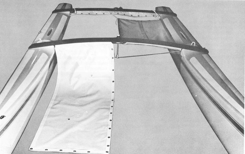
7 Figure 8 5 Figure 9


8 5. Insert the aft outboard corner of the trampoline into the extrusion on the inside of the hull and pull the trampoline as far aft as it will go. 6. Repeat steps 2-5 for installing the starboard trampoline. 7. In front of the rear cross bar there is a hole in either inboard rail. Insert the port aft lacing line into this hole on the port hull and exit it straight down. Tie a knot in the tail of the line and then pull the knot up under the rail. Figure Thread the lacing line from the inboard rail to the corner grommet on the AFT lacing strip and then to the corner grommet on the port trampoline. Temporarily tie the line off to the rear cross bar. 9. Repeat this procedure for the starboard side of the trampoline. 10. Attach the center trampoline lacing line to the forward-most grommet on the starboard trampoline. Lace it down to the rear taking out the slack as you go. 11. Untie the aft lacing lines and complete the lacing starting at the outboard side and working toward the center. See Figure 10. With use the trampoline will stretch and require periodic re-tightening. Figure 11 6
, is the spreader arm. Attach it to the aft tab of the spreader root (1-2). Use a 3/16\" x 11/16\" clevis pin (1-3).")
 on the spreader arm so that the large wing of the slide is closest to the mast, and facing forward. 5.")
9 MAST ASSEMBLY 1. Support mast at both ends on saw horses or other such devices. Ref: Illus. #1, Pg Spreaders. In the rig kit you will find all the parts of the spreader assembly. 3. The larger of the two pairs of aluminum rods (1-1), is the spreader arm. Attach it to the aft tab of the spreader root (1-2). Use a 3/16" x 11/16" clevis pin (1-3). turnbuckle on the bolt, pass the bolt through the mast at the compression sleeve which is located 1 foot above the mast base(1-14). The shackled end of the MRCY should be behind the mast. 4. Locate the slide (1-4) on the spreader arm so that the large wing of the slide is closest to the mast, and facing forward. 5. Line up the inboard hole on the slide with the outboard hole on the spreader arm and insert the slide adjustment pin 3/16" x 13/16" (1-5). The slide is now positioned in the raked forward attitude. 6. Connect the smaller brace rod (1-6) between the forward tab on the spreader root and the wing on the slide, with the brace pin 3/16" x 9/16" (1-7). 7. Secure all the clevis pins with the cotter keys provided. 8. Repeat steps 3-7 for the opposite side of the mast. 9.There will be two large cotter pins (1-8) left over, place them to one side, they will be used later to retain the diamond wires in the spreader arm tips. 10. Mast rotation control yoke (MRCY). In the rig kit you will find the parts of the MRCY. You will also need the diamond wires which can be identified by the turnbuckles on one end. 11. IMPORTANT follow this sequence to assemble the MRCY and diamond wires. 12. Hold the two arms of the yoke (1-9) together at the ends with the small holes. Attach the small block (1-10) and shackle (1-11) to this end, see Figure 12. (There is a short line packed with the MRCY, set it to one side for now.) 13. Pass the long bolt (1-12) NOTE: The style of rotator yoke shown in Figure 12 is the older mast rotator style. Current models do not have a pulley. See page 20 for details on the new style. through the large hole in one arm of the MRCY (1-9). Slide the toggle of diamond wire turnbuckle (1-13) over the bolt and move it next to the MRCY arm. 14. With one arm of the MRCY and one diamond wire turnbuckle on the bolt, pass the bolt through the mast at the compression sleeve which is located 1 foot above the mast base( 1-14). The shackled end of the MRCY should be behind the mast. 15. Slide the turnbuckle toggle of the opposite diamond wire over the exposed portion of the bolt. Install the remaining arm of the MRCY on top of the turnbuckle toggle. 16. Put the retaining nut (1-15) on the exposed threads of the bolt and finger tighten only. It will be tightened later. See figure Loosen the lock nuts at each end of the turnbuckle body and expand the turnbuckle 2-1/2". Note that both lock nuts spin in the same direction to unlock. 18. Attach the opposite end of the diamond wire to the diamond wire tang (1-16) which is located 2 feet below the mast tang (1-17). Install clevis pins (1-19) and cotter pins (1-20). Figure 12 Figure 13 7
 through the tip of the spreader. 20. Repeat this procedure for the starboard diamond wire. 21.")

10 19. Slip the port diamond wire into the tip of the port spreader arm. Make sure that the anti-chafing roller on the diamond wire is above the spreader tip. Secure the diamond wire by installing one of the long cotter pins (1-8) through the tip of the spreader. 20. Repeat this procedure for the starboard diamond wire. 21. Tighten the nut (1-15) of the through mast bolt which is at the lower end of the diamond wires. 22. Tighten the diamond wires by rotating the turnbuckle bodies. The turnbuckles must be adjusted equally since over-tightening one side will induce a bend into the mast. See Figure Locate the shrouds and forestay in the rig kit. They are packed together and are the only rigging which is vinyl coated. The three wires are already attached to a large shackle. Remove the pin from the shackle and attach it to the mast tang (1-17) at the lowest of the. holes in the tang. See Figure 15. Secure the safety wire, which is attached to the thumbscrew, to the shackle body. This will keep the pin from unscrewing. 26. The double trapeze wire has a single thimble at its upper end. Engage this thimble to the shackle on the opposite set of trapeze wires after you have inserted the shackle through the upper set of holes in the mast tang. See Figure 15. Figure 14 WARNING The diamond wire adjustment not only affects boat performance but also affects the mast structural integrity. If the diamond wires are loose or broken the mast will be permanently distorted or could fail completely. The diamond wires cannot be tightened sufficiently by hand. It will require the assistance of a wrench to make the last two or three revolutions of the turnbuckle body. Additionally, the diamond wire will stretch with use and require periodic inspection and re-tightening. 23. Once the diamond wires are adjusted, spin the locknuts up against the turnbuckle body tight. You can do this by hand. Figure Tie a piece of string through one turnbuckle body and over through the other turnbuckle body. This will keep the turnbuckle from unscrewing. 8

11 STEPPING THE MAST. DANGER - Do not attempt to step the mast in an area of low overhead wires. A mast contacting an electrical wire could be fatal. 1. Secure the four trapeze wires near the bottom of the mast so that they will be out of the way while the mast is being raised. 2. Attach the jib halyard line to each end of the jib halyard wire to form a very large loop. Tie the line around the fork at the bottom of the forestay. The halyard line must be connected to the wire before the mast is raised or you will be unable to hoist the jib later. See Illustration. 3. Carry the mast over to the boat and place the hinge of the mast base over the mast step which is located on the front bar, see Figure 17. The sail track should be facing down. Note: when lowering the mast over the trampoline be sure to guide the mast rotation control yoke between the trampoline halves. Jib Halyard Wire Luff Tensioner Jib Halyard Line Figure 16 Figure 17 9


12 CAUTION: We recommend two people for stepping the mast. It is heavy for one person and could slip causing injury or damage. 8. Stand on the trampoline next to the back bar and raise the mast to your shoulders. Make sure the shrouds are not fouled and the stay adjusters are free before advancing further. Do not raise the mast in an area with any overhead wires. If everything is clear walk straight ahead raising the mast as you go. See Figures 20, 21, and With the hinge in place over the step insert the mast step pin through the entire assembly so that it is visible on the opposite side on the hinge. 5. Attach the bridle wires to the bow tangs. Attach the roller furler mechanism between the bridle wires. Make sure the oblong hole in the roller furler is aft. See Figure Attach the port shroud to the port stay adjuster and the starboard shroud to the starboard stay adjuster. Secure the shrouds to the top hole in the stay adjuster at this time. See Figure Secure the base of the stay adjuster to the anchor pin on the respective hull. Figure Once the mast is in the vertical position lean your weight against the mast to hold it in place. The second person can now let go of the mast and attach the forestay to the top of the stay adjuster which extends from the roller furler assembly. See Figure 18. Figure Remove the mast step pin only after the forestay has been secured. Store the pin in the pouch on the trampoline. 11. Once the mast has been raised untie the trapeze wires. In the rig kit you will find a bag which contains 4 trapeze dogbones, 4 rope locks and 4 trapeze adjusting lines. 12. Tie the adjusting line onto one of the shockcord loops which is located at the outside rail adjacent to the stay adjuster. Figure 21 Figure 22 Figure 19 10


13 13. Lace it through the rope lock and then through the thimble at the end of the trapeze wire. Now tie the line onto either end of the dogbone. See Figure Repeat this process for the other three trapeze wires at the respective locations. block on the end of the mast rotation control yoke and then feed it through the jam cleat. Tie a knot in the end of the line so that it will not slip back through the jam cleat. See Figure 35. Once again, be sure to note that this is the older style of mast rotator. With the newer style, the line does not run through a pulley, but through a ring at the end of the control yoke. Run the line through the ring and into the jam cleat. Figure 24 JIB BLOCK INSTALLATION 1. The large jib blocks are packed in the rig kits. Remove the jib track end stop on the jib track and slide the car on the bottom of the block into the track. See Figure 25. Note that the slide adjustment knob is aft of the block assembly. Figure 23 BOOM INSTALLATION 1. Attach the gooseneck pin which extends from the front of the boom to the gooseneck yoke on the mast. See Figure Tie the line which was packed with the mast rotation control yoke to the forward-most jam cleat on the boom. See step 11 of mast assembly. Run the line through the Figure 25 11
14 Hobie 18 and SX18 UPDATES INSTALLING THE RUDDER ASSEMBLY The rudders were updated after The newer rudders use a black plastic cam to lock the rudder in the down position. Locate the left and right rudder assemblies. The left one has a red dot and the right one a green dot. The tiller arms should have a slight bow towards the centerline of the boat. INSTALLING THE SAIL BATTENS Unfold the sail and lay it out on the trampoline. There will be a small bundle of thin lines tied to the top of the sail. These are the batten tension lines. Tie the batten tension lines to one of the small grommets at the end of each batten pocket as diagramed in figure 28 (one to each batten pocket). Tie the lines using a bowline knot Figure 28 As shown in the original instructions, position the rudders at the transom. There are two bushings and two washers provided with the each new assembly. Slide the bushings in from the bottom and place the longer one in the lower casting hole. Install a cotter key in each rudder pin. Assemble as shown below. Then insert the remaining cotter keys in the top of the rudder pins to hold the rudders in place. INSTALLING THE TILLER CONNECTOR The tiller arms have swivels on the ends. Point the connector rods upwards and slide the tiller connector end fitting over the rods. Place the adjustable end of the connector rod to the port (left) side of the boat. Pull the small tabs forward and over the rod and lock them in the slots. Rudder toe-in adjustments can be made with the threaded end fitting on the tiller cross bar. Typical adjustment has rudders in parallel. Figure 27 Figure 26 as found in the "knots" diagramed on page 4. It is best to tie the lines all to one side of the sail. Insert each batten (shortest batten at the top to longest batten at the bottom of the sail). Note that the batten ends have a "V" jam cleat molded into them. These "V" jam cleats will keep the tension line from slipping in only one direction. Note the hollowed-out side of the cleats. Pull the line from the flush side toward the hollowed side. The upper batten is narrower and has a different cleat shape. To be sure this cleat works correctly, position it so that the hollowed out side of the cap faces the bowline that you have tied to the sail grommet. Position the larger caps so that the hollowed sides face away from each knot. Following the diagram in figure 28, lace the tension lines through each batten end cap. Pass the line through the hole in the cap, then through the grommet on the opposite side. For the smaller caps, pass the line over the "V' cleat, pull tension forcing the batten into the pocket, then pull the line into the cleat to hold it. For the larger caps, pass the line through the second hole in the cap, then pass the line through the first grommet and back to the "V" cleat. Pull tension on the line forcing the batten into the pocket and cleat it. Tie a small figure 8 knot in the end 1 of each line to prevent the battens from falling from the sail if the line releases from the cleat. Tension each batten so that the batten is well seated and the wrinkles in the batten pockets are removed. Excessive batten tension will cause the sail to be more difficult to handle. 12


15 RUDDER AND TILLER CROSS BAR INSTALLATION (Pre 1987 boats) 1. Disengage the tiller arm from the lower casting and lock the tiller arm and rudder in the kicked up position. This will pull the rudder blade up and out of the way so the rudder pin can be installed. 2. Hold the lower casting up to the transom of the boat and fit the casting over the gudgeons. Slide the rudder pin up through the casting and gudgeons with the hole in the rudder pin closest the bottom. Once the hole in the pin is above the casting at the lower gudgeon, stop and insert the cotter key which is packed with the rudder pins. Bend over the legs of the key to secure it in place. The rudder can be lowered now. See Figure 29 and To distinguish the port rudder from the starboard rudder, the port rudder arm will bend toward the center of the boat when on the port hull. 4. Attach the tiller cross bar to the tiller arm as shown in figure 31. Figure 31 Figure 29 Figure 30 Figure 32 13


16 RAISING THE SAILS 1. Point the boat into the wind before you begin this operation. 2. Lay the main sail out on the trampoline. Insert the battens into the batten pockets starting at the top of the sail and working your way down. The batten has a tip on each end. The end without any holes goes into the sail first. Slip the batten in until it seats into the batten pocket protector at the leading edge of the sail. 3. Thread the batten tie through the aft batten tip and the sail as shown in Figure 33. Secure the end of the batten ties with a figure eight knot. Figure Attach the twist shackle on the end of the main halyard to the grommet in the headboard and feed the sail into the sailtrack in the mast. See Figure 34. Note the metal ring connected to the twist shackle. It will engage the latching mechanism at the top of the mast. (see Figure 34a). Continue to raise the sail by pulling the main halyard out from the base of the mast. Figure 34 Figure 34a 5. It is recommended that you lubricate the leading edge of the sail with paraffin from time to time to reduce wear from the sail track. It will also make it easier to raise the sail. 6. Raise the sail until the metal ring above the halyard shackle engages the halyard hook at the top of the mast. Store the excess halyard line in the pouch on the trampoline. 7. Tie the downhaul line to the tack of the sail and lace the downhaul as shown in Figure Attach the outhaul car on the boom to the clew of the main. See Figure To lower the main, untie the downhaul and slide the leading edge of the sail up the sailtrack a few inches. Next pull hard on the main halyard and the metal ring and the top of the sail will overrun the halyard hook, rotate the mast to the starboard then release the halyard. 14


17 Figure 35 Note: Old style mast rotator shown here. 10. Attach the three boom blocks to the hangers on the boom. Secure the ratchet block to the top of the traveler car. Thread the mainsheet through the blocks as shown in Figure 37. Slip the other end of the mainsheet through the traveler jam cleat, then guide the line through the center of the traveler, and secure at the dead eye on the back bar. 11. With only the main sail up tighten the shrouds. First move the traveler car all the way over to the port side of the back bar. Next pull the mainsheet in very hard. The port shroud should be slack now and can be moved down in the stay adjuster. Repeat this procedure for the starboard shroud. Note: Tension on the shrouds must be relieved before lowering the main sail. If you intend to unstep the mast. H18SX Downhaul Instructions 1. Using the twist shackle, attach the double block to the sail luff grommet. 2. Tie off the downhaul line (10' of 3 /16" yt braid) to the sail luff grommet. 3. Run the line through the cheek block on the left hand side of the gooseneck yoke. 4. Continue to the double block, then to the cheek block on the right hand side of the gooseneck yoke, then back through the second sheave on the double block. 5. Tie off on mast downhaul cleat located below the boom. Figure Figure 37


18 Raising the Jib 1. Attach the shackle on the end of the jib halyard wire to the head of the jib. 2. Wrap the luff pocket of the jib around the forestay and engage the zipper an inch or so. Next thread the jib halyard line inside the luff pocket. See Figure 38. Figure Thread the remaining portion of the jib sheet through the starboard jib block in this same fashion. Figure Raise the sail by pulling on the jib halyard line and at the same time advance the zipper down the luff until the jib tack is even with the roller furling housing. 4. Attach the jib tack to the shackle on the neck of the roller furling housing.. 5. Untie the jib halyard line and connect the luff tensioner to the block on the end of the jib halyard. Thread the tensioner down through the tack shackle, then back up through the block on the jib halyard. Secure the line in the jam cleat on the sail. See Figure IMPORTANT. Only apply the jib luff tension after the shrouds and forestay have been tightened. To do so beforehand could result in the jib halyard being broken when the slack in the shrouds is taken up. 7. Attach the jib clew blocks to the jib clew, see Figure Thread the jib sheet through the port jib block, then around the jib clew block. Take the line back and tie it off at the becket on the jib block. See Figure The roller furler line can be temporarily secured in the jam cleat on the back side of the front cross bar. Roller furler line adjustment on take up spool. a. Disconnect jib clew blocks from jib clew. b. Pullout the roller furler line from the housing until the take up spool is empty and secure the line to the cleat on the front bar. c. Wrap the sail clockwise around the forestay until it is completely furled. d. Reattach the jib clew blocks to the jib clew. The jib is now in the furled position. To unfurl the jib, release the roller furler line which is cleated on the front bar, and pull on the jib sheet. Figure 40 Figure 41 To furl the jib, release the jib sheet (both port and starboard) pull the furler line until the jib is completely furled. Do not partially furl the sail, this will cause uneven stretching of the exposed sail.

19 Figure 42 DAGGER BOARDS 1. Slip the shock cord through the hole in the upper portion of the dagger board, take both ends to the hole on the out board deck flange. Pass both ends through the hold and tie a knot under the rail. 2. Pass the rope handle through the same hole in the dagger board as before. Tie the two ends together to form a large loop which will serve as the handle. See Figure When raising or lowering the board do not rock it fore and aft. This will cause damage to the trailing edge. Pull the leading edge of the dagger board aft about 1/4 of an inch so that it is not contacting the lip of the deck and it can be easily moved up and down. 4. IMPORTANT. If you expect contact with an object or the shore, pull the dagger boards up out of the way. Severe damage can resuit if the boards contact any solid object regardless of the speed. 17
20 HOBIE CAT T 18 18
21 INDEX NO. DESCRIPTION 1 Arm 2 Brace 3 Slide 4 Diamond Wire (one side) 5 Gooseneck Yoke 6 Check Block 7 Mast Rotation Line 8 Modified Swivel Block 9 Shackle 10 Mast Rotation Assembly 11 Pin-Pawl Bearing, Ring-Halyard Line 13 Hook for Halyard Lock Assembly 14 Jib Furling Assembly 15 Bridle Wire Assembly 16 Screw (1/4 x 20) 17 Back Up Plate - Bow Tang 18 Nylock Nut (1/4 x 20) 19 Mast Tang 20 Trapeze Wire (one side) 21 Shackle 22 Shroud 23 Pigtail with Swivel 24 Jib Halyard Block Assembly 25 Clevis Pin 26 Mast Hinge Casting 27 Mast Base Casting 28 Screw RD. HD. 1/4 x Star Lock Washer 30 Sheave 31 Clevis Pin 32 Washer 33 Bushing 34 Pad. Mast step 35 Mast Step 36 Rivet 37 Left Front Corner Casting 38 Boom Outhaul Slide Assy. 39 Cotter Key 40 Outhaul Car 41 Clevis Pin 42 Sheave 43 Rollers 44 Pin 45 Outhaul Line 46 Boom 47 Boom Block 48 Single Block with Becket 49 Boom Block 50 Main Sheet Line 51 Triple Block 52 Left Rear Corner Casting 53 H-18 Ratchet Block 54 Traveler Assembly 55 Channel 56 Bushing 57 Bolt 3/8 x 16-3 (rear only) 58 Swivel Main Sheet Fairlead 59 Rear Crossbar 60 Tiller Crossbar with Rudder Adjuster 61 Tiller Arm Bent 62 Upper Rudder Arm Right/Starboard 63 Right Rear Corner Casting 64 Channel 65 Nylock Nut - versus drawing 66 Upper Rudder Casting 67 Lower Rudder Casting - bare 68 Rudder Pin 69 Lower Gudgeon 70 Jib Sheet Line 71 Jib Sheet Block 72 Front Crossbar Assembly 73 Right Front Corner Casting 74 Bolt - Cover Plate 75 Flange 76 Storage Cover w/handle 19
22 New Style Yoke Old Style Yoke 1-1 Spreader Arm 1-2 Spreader Root 1-3 Clevis Pin 3/16" x 11/16" 1-4 Slide 1-5 Clevis Pin 3/16" x 13/16" 1-6 Brace 1-7 Clevis Pin 3/16" x 9/16" 1-8 Cotter Pin 1-9 Mast Rotation Control Yoke 1-10 Block 1-11 Shackle 1-12 Bolt 4-1/8" Lg Diamond Wire 1-14 Mast Base Assembly 1-15 Nut Nylock 1-16 Diamond Wire Tang 1-17 Mast Tang 1-18 Mast Extrusion 1-19 Clevis Pin 3/16" x 1/2" 1-20 Cotter Pin Illustration No. 1 Mast Assembly 20
23 2-1 Jib Block Housing 2-2 Jib Halyard Wire 2-3 Luff Tensioner 2-4 Jib Halyard Line 2-5 Jib Block Sheave 2-7 Clevis Pin 2-8 A Cotter Pin 2-9 Swedge 2-10 Thimble 2-11 Block 2-12 Shackle Illustration No. 2 Jib Halyard Assembly 3-1 Bolt 3-2 Half Ball 3-3 Tiller Crossbar 3-4 Plastic Washer 3-5 Tiller Arm 3-6 Washer 3-7 Spring 3-8 Nut Illustration No. 3 Tiller Connector Kit 21
24 *Rudder system Pre-1987 shown Illustration No. 6 Rudder Assembly 6-1 Rudder Blade-Drilled 6-2 Lower Rudder Casting Assembly 6-3 Port Upper Rudder Housing Assembly 6-4 Nut Nylock 6-5 Bolt 2" Lg 6-6 Spring 6-7 Delrin Screw / 4" I.D. Nyliner 6-9 Rudder Cam 6-10 Upper Rudder Housing Casting 6-11 Rivet 6-12 Locking Sleeve 6-13 Pin Upper Rudder Housing 6-14 Pin Lower Rudder Housing 6-15 Tiller End Cap Illustration No. 7 Outhaul Car Assembly 7-1 Adjuster Pin Retaining Ring 7-2 Outhaul Slide Car 7-3 Clevis Pin 1 /4" x 7 /8" 7-4 Ball Roller Bearing 7-5 Clevis Pin 1 /4" x 5 /8" 7-6 Pin-Bearing 7-7 Sheave 7-8 Cotter Key 22
25 Illustration No. 8 Traveler Assembly /4" Lg H.H. Bolt 8-2 Deck Plate 8-3 Sheave 8-4 Spacer 8-5 Car Assembly 8-6 Cotter Pin 8-7 H.H. Nuts-Nylock 8-8 Bearing Cylinder 8-9 Pin-Clevis 8-10 Bearing Ball Illustration No. 9 Roller Furler Assembly 9-1 Upper Retaining Ring 9-2 Top Nyliner 9-3 Bottom Nyliner 9-4 Yoke 9-5 Housing 9-6 Interior Retaining Ring 9-7 Bearing Sleeve 9-8 Bearing Race 9-9 Bearing Cage 9-10 Bearings 9-11 Tube 9-12 Spool 9-13 Screw Truss Head 23
26 Illustration No. 10 (old style) Dolphin Post Assembly 10-1 Screw RHMS 10-2 Internal Lock Washer 10-3 Washer 10-4 Mast Step Pad 10-5 Bushing 10-6 Mast Step Casting 10-7 Dolphin Striker Post 10-8 Dolphin Striker Sleeve Illustration No. 11 (new style) Dolphin Post Assembly 11-1 Screw RHMS 11-2 Washer 11-3 Bearing 11-4 Mast Step Casting 11-5 Dolphin Striker Post 11-6 Dolphin Striker Sleeve 24
27 Illustration No. 12 (new style) Tiller Connector 12-1 Tiller Connection Rod 12-2 Tiller Arm Swivel End Cap 12-3 Tiller Arm Insert 12-4 Bolt 12-5 Washer 12-6 Insert Bearing 12-7 Retainer Clip 12-8 Screw Parts Relating to Diagram on Page 2 11 Trapeze Seat Assy. 2 Trapeze Seat 2 Trapeze Hook 2 Trapeze Lacing Line 6' 12 Mast Rotation Control Yoke Assy. 2 Mast Rotation Control Yoke 1 Shackle 1 Block 1 Mast Rotation Control Line 3' 1 Mast Rotation Control Yoke Retaining Bolt 1 Retaining Bolt Nut 13 Spreader Assy. 2 Spreader Arm 2 Brace 2 Slide 2 Spreader Arm Root Pin 3/16" x 11/16" 2 Spreader Arm Slide Pin 3/16" x 13/16" 4 Brace Pin 3/16" x 9/16" 8 Cotter Pins 1/2" 2 Spreader Arm Tip Cotter Pins 3/4" 14 Adjustable Trapeze Equipment 4 Dogbone 4 Rope Lock 4 Adjustable Trapeze Line 30" 15 Dagger Board Kit 2 1/4" Shock, Card 46" 2 1 /4" Rope Handle 29" Hole Stay Adjuster Assy. 2 Drain Plug 2 Drain Plug Gasket 1 Tiller Connection Kit Rudder Pin 2 Cotter Pin for Rudder Pin 2 Jib Clew Block 1 Shackle 1 Gooseneck Vertex 1 Clevis Pin " 1 Split Ring 1 Gooseneck Bolt 1 Nut 17 A 1 Down Haul Line 18 Bridle Wire Clevis Pins 4 Bridle Wire Clevis Pins 4 Split Rings 18A Diamond Wire Clevis Pins 1 2 Upper Diamond Wire Clevis Pins 2 Cotter Pin 19 Mast Step Pin 1 Mast Step Pin 1 Split Ring 1 Mast Step Pin Retaining Line 20 Traveler Bearing Kit 1 Traveler Bearing - Ball 1 Traveler Bearing Slug 1 Long Cotter Pin 21 8 Retaining Channel 2 Front Bar Inboard Bolt 3 3/ 4" 2 Front Bar Outboard Bolt 2" 2 Rear Cross Bar Inboard Bolt 2 1/2" 2 Rear Cross Bar Outboard Bolt 2" 4 Lock Nuts for Outboard Bolts 2 Bridle Wire 2 Diamond Wire 2 Trapeze Wire
28 SAILING YOUR HOBIE 18 Safe and sane guideline for the beginner; and an easy review for the experienced. Always wear a life jacket when boating. BALANCING THE BOAT When sailing, sit on the upwind side of the boat (wind on your back) just in front of the tiller, facing the sail. Balance your weight further outboard as the boat begins to tip or heal over with the wind in the sails. Tuck one foot under the hiking strap for balance. Use your hand that is forward to hold and control the mainsheet. Use your hand that is aft to steer. Refer to the sail trim diagram below for approximate sail settings for the different points of sail or directions you will be sailing. Note the "can't sail zone". You cannot sail in this direction due to the fact that the sail will luff constantly when pointed into the wind. If you get stuck in irons (or stop pointed into the wind) you will need to reverse the rudder and push the sail forward to backwind it. The jib should be back winded by the crew to assist. This will back the boat up. Reverse the rudders and let the sail out until the boat is positioned more across the wind (close reach). Then you can correctly trim the sail and start moving forward. STEERING Steer the boat by pushing the tiller away from you to turn towards the wind. Pull the tiller towards you to turn away from the wind. Keep the movement of the tiller to a minimum to prevent over-steering. This will help you keep the boat moving in a straight line as you pay attention to other watercraft and sail adjustments. SAIL POWER Face the sail in order to pay close attention to the trim or adjustment of the sail. When the front of the sail, just behind the mast, luffs or flutters in the breeze, you lose power. To start moving, pull the sail in just enough to stop the sail from luffing. There are also short ribbons hanging on either side of the sail. Follow the diagram of sail and course adjustments above using the "tell tails" to get the most performance out of the sail for all angles of sailing. The tell tails react to air flowing over the sail and will help you see that the sail is pulled in too tight or too loosely. If you pull the sail too tight you will stall the sail power. Ease the sail out until it luffs, then pull it in just a little until it stops luffing. You will adjust the trim whenever the wind changes direction or you change course. WIND CAN'T SAIL IN Close Hauled THIS AREA Close Reach Medium Reach Medium Reach Broad Reach Downwind Run Close Hauled Close Reach Broad Reach FALLING OFF HEADING UP WIND COMING ABOUT 26
29 TURNING To tack or turn the boat into and across the wind to the opposite direction (also known as "coming about"), follow the points of sail guide illustration and take the boat to the close hauled point of sail. This is when you are nearly 35 degrees from sailing straight into the wind. With the boat moving forward and not stalling, push the tiller away from you slowly. When the boat is pointing straight into the wind the boat will become level. Ease the mainsheet trim out just a little. At this time move your body to the other side of the boat, switch hands with tiller and mainsheet and begin to bring the rudder back to straight. The crew should move across the trampoline at the same time. The crew is responsible to ease the jib sheet just after the main sail is released and sheet the jib onto the new course before the mainsheet is trimmed. This action by the crew will prevent the boat stalling head to wind. As the boat comes across the wind and falls off onto the opposite, close hauled point of sail, bring the tiller all the way back to the straight position and pull the mainsail back in for the proper sail trim. If you stall pointing into the wind and you cannot steer the boat, refer back to the sail power description concerning getting stuck in irons. When sailing downwind, the turn from one point of sail across to the other is called a jibe. The jibe is completed by turning away from the wind (falling off) to the opposite point of sail rather than into the wind as when tacking. Care must be taken when attempting a jibe as the boat will be at full power and you cannot easily depower it without turning back into the wind. Also, be aware that the boat will be less stable in this maneuver as the sail will now have to swing clear across from fully out one side of the boat to fully out the other. To start a jibe, turn the boat away from the wind and let the sail out slowly. Keep the turn going at a steady rate and begin pulling the sail back in as the boat nears the straight downwind direction. This will help prevent the sail from slamming all the way across when the sail fills from the opposite side. Duck below the sail to avoid getting hit as the wind fills the sail from the opposite side and swings across the boat. Attempt to control the speed of the sail while it crosses the deck by maintaining some tension on the mainsheet. Then ease the mainsheet out quickly as the boat turns past the downwind direction onto the new point of sail. Trim the sail correctly for the desired point of sail. LAUNCHING THE BOAT Launching the boat is easiest when the boat can be pointed into the wind to keep it de-powered and floated 27 into deep enough water to lower the rudders. It is possible to launch in shallow water with the rudders partly up. Try not to steer with too much force on the rudders until you lock them in the down position. Keep the sail loose and trimmed out completely until you can power up and steer away from any obstacle. Trim the sail in quickly to get the boat moving forward and steer away from the wind slightly to prevent stalling into the wind. When launching from a beach where the wind is blowing from the beach towards the water you simply keep the boat pointed into the wind. Drift backwards with the rudders in the up position and your weight towards the front of the boat. Stay forward as the boat drifts into deeper water.you can hold the sail out to catch wind backwards to increase reverse speed. Then move to the rear and lower the rudders. It will be easiest to lower only one rudder while moving backwards. Then lower the other when the boat begins to move forward again. Be aware of the intended direction you wish to sail when lowering the rudder and steer the boat as the rudder drops into the water. There will be a lot of force on the rudder to turn one way or the other when going backwards. Plan ahead and steer the rudders so that they will be pointing in that direction before dropping it into the water. Steer the boat while going backwards so the bow turns away from the wind and toward the direction you wish to sail. As the sail begins to fill with wind, the boat will slow then begin to move forward. Trim in the sail and off you go. RIGHTING THE BOAT If you tip the boat over, stay with the boat. The boat will not sink and is easy to right. It is not necessary, but it is easier, to right the boat when the bow and the mast are pointed into the wind as in the following diagram. There will be less wind resistance and better control in this position. Be sure the mainsheet is released, then swim around to the bottom of the boat. Skipper and crew should climb up on the hull and stand up. Using the righting line, skipper and crew pull the righting line that is against the upper hull and hold the
30 line while slowly leaning back away from the trampoline. Lean to approximately 45 degrees for best leverage. As the mast and sail lift out of the water and the upper hull begins to drop back into the water, drop down to your knees then into the water. Hold onto the righting line near the crossbar or the crossbar itself near the hull that you were standing on. This will prevent the hull from being lifted into the air by momentum which could cause the boat to capsize once again. Be well aware of the hull and crossbar coming down over your head. Holding the crossbar or righting line will also insure that you remain with the boat when it is righted. Climb aboard and continue sailing. Be well aware of the hull and crossbar coming down over your head. Holding the crossbar or righting line will also insure that you remain with the boat when it is righted. DOCKING Docking the Getaway properly will prevent damage. Always dock and rig on the leeward side of a dock (the side the wind reaches last). Come in slowly and always be aware of the wind direction so you can properly depower the boat when needed. The stronger the wind the more difficult the docking will be. Until you feel confident, you may want to practice with a friend who will remain on the dock and help slow you down if necessary. BEACH LANDINGS Landing on a beach is simple. The idea is to reach the beach in the point of sail nearest straight into the wind as possible. This will assure that you can properly depower the sail once beached. Approaching a beach when the wind is blowing from the beach out towards the water will require some planning so that you maintain power. Turn into shore just before the hulls or rudders touch bottom. Plan so the final tack towards the location you choose to land is the tack that is nearest straight into the wind. Get a little closer to the beach than you need on the pervious tack to account for wind shifts in direction and speed. This will give you a little room for error. This will allow you to point a little further away from the wind after the tack to gain speed before heading up into the beach to de-power at the last moment. When approaching a beach when the wind is blowing onshore, sail in towards the beach from either side of the landing spot. Sail in just short of touching the bottom with the rudders. Allow some distance to turn the boat out towards the water and into the wind just out from the landing spot. Turn sharply to head into the wind and 28 stall the boat. Raise the rudders and drift back onto the beach. Always keep the boat pointed into the wind while beached and keep the sail trimmed out and uncleated. RUDDER TUNING You may adjust the rake of your rudder blades on your Hobie Getaway. The amount of rake in a rudder blade affects the "feel" at the tiller. Basically, more forward blade rake neutralizes the pull on the tiller and less forward rake increases the pull on the tiller. Tuning blades for a comfortable feel is a matter of individual preference but a close to neutral "feel" generally provides the best steering. The following sketches are of a Hobie 16 rudder assembly but the adjustments are the same. 1) The first step in making any rudder rake adjustment is to determine the existing rake. This is done with the rudder assembly hanging on the boat's transom, blade down and locked. Using a straight edge or snap line, extend the centerline of the rudder pivot pins down, across the leading edge of the blade and draw a pencil 12" Aft for more pull on the tiller 1-1/8" Forward for less pull on the tiller line along that length. Measure the distance from the pencil line to the most forward spot 12" down the blade from the bottom of the casting. Rudder blade rake is pre-set at the factory to 1-1/8". This amount will be best for the average sailor and is a good starting point from which to begin any adjustments. 2) To make any adjustment to the rake, unlock the tiller arm from the rudder housing and leave it unlocked. 3) If you wish to increase the amount of forward rake in the rudder blade, turn the rake adjusting screw counterclockwise using a 3/16" Allen wrench. Determine the increase in the rake by extending a new line from the centerline of the pivot Screw pins. Re-measure the distance from the pencil Sketch B line to the leading edge.
31 Continue to adjust and measure until you have the desired amount of forward rake. 4) If you wish to decrease the amount of forward rake turn the adjusting screw clockwise using a 3/16" Allen wrench. Check the decrease in the rake by the procedure in step 3 above. 5) Next, while holding the rudder forward against the lower casting, carefully latch the tiller arm down onto rudder housing. Loosen the adjusting screw on top of the tiller arm about 3/4 turn. Slide the adjusting screw forward (toward bow of boat) until it stops, then retighten. See sketch C. Sketch C 6) Hobie Cat rudder blades are preset to break away from the locked down position at pounds by testing with a line around the rudder blade seven inches above the lowest tip of the blade. Once the rake is changed, the breakaway tension should be rechecked. The tension may be adjusted by turning the 3/4" internal screw in the housing. The screw tensions an internal spring. Turn it clockwise to increase and counter clockwise to decrease the tension. Screw TRAILERING CAUTION: Boat and mast should be securely attached to trailer with adequate tie-down straps. Failure to do so could cause extensive damage or serious injury! LOADING YOUR TRAILER The weight of the boat, equipment and additional gear should never exceed the manufacturer's rated weight capacity. Proper distribution of the load is of vital importance. Too much weight on the hitch will cause 29 "tail dragging" of the towing vehicle, impairing steering and raising headlights into the eyes of oncoming traffic. Too little or negative weight on the hitch, and the trailer will sway or "fishtail". The solution to proper distribution is often adjusting movable gear. A more permanent solution is to shift the axle position before taking your boat to water the very first time. TOWING Extra caution is necessary when towing any trailer. The heavier the rig, the more time required to accelerate, pass, and stop. For this reason, the maximum speed for vehicles with trailers is less than without a trailer in most states. A long rig requires a larger turning radius. Curbs and obstructions should be given wide clearance. Most boats on trailers obstruct the rear view of the driver. When this happens, an additional rear view mirror on the right side of the towing vehicle is required by law. The trailer boatman should be familiar with traffic and highway laws relating to the towing of trailers. Towing a Hobie has particular hazards that should be mentioned. A Hobie is very wide. Obstacles should be given plenty of room when you are passing them. Tie down straps or lashings should be of sufficient size and diameter and placed on all four corners. The mast support on a trailer is subject to a lot of side-to-side motion and consequently may fatigue where it is welded to the trailer. All this can be reduced by tying a line from each bow to the mast support. This will stiffen the rig up and prolong the life of the trailer. LAUNCHING AND RETRIEVING Prepare boat for launching at the top of the ramp or parking facility. Remove all tie-down straps, check boat plugs and fasten boat painter. Do not release winch line until the boat is in the water. Back trailer to the left if possible; backing left gives better launching visibility. Avoid dunking wheel bearings wherever possible. Never leave the towing vehicle unattended on the ramp with only the parking brake set. If vehicle must be left while on the ramp, set transmission in "park" or first gear, in addition to setting the parking brake. In retrieving your boat, make sure that the boat is properly placed on the trailer. Pull trailer up steadily to prevent spinning the wheels. MAINTENANCE Lights: Most state laws require two red taillights on the rear that may be combined with the stop and turn signals. Vehicles over 80 inches in width require clearance lights. If lights are dunked, waterproof light fixtures should be used. If water is allowed to enter, the lamp may crack and short out the entire system. Water also promotes contact corrosion. Always carry spare
32 lamps. The wire coupling to the towing vehicle should be high enough to stay dry. Never rely on the trailer hitch for ground connection. Four-pole connectors should be used. The mast should not extend over three feet behind the rear light assembly. Wheels: Tires should ALWAYS be inflated to manufacturer's recommended pressure. Always carry a spare wheel and a jack that fit the boat trailer. If wheel bearings are always dunked, waterproof bearings and caps should be considered. If water is allowed into the hub, lubricating grease will float away and bearings will burn out or seize, causing damage and a safety hazard. Waterproofed bearings should be inspected prior to each boating season, others more often. Special care should be given when traveling on unimproved roadways with small diameter wheels. If a spare wheel is not available, a spare wheel bearing set should be taken on long trips in case the grease seal has been broken. FRAME AND ROLLERS Rust should not be allowed to accumulate. Remove rust and repaint with anti-rust paint. Some trailers offer galvanized coating to prevent rust. Rollers should roll freely and should not have checks, breaks or flat spots. TOWING VEHICLE Most vehicles are limited in towing capacity. Towing heavy loads places extra demands on the engine, transmission, brakes and other systems vital to the vehicle. Towing "packages" are available through most auto dealers and should be considered for heavy boats. MOORING: Mooring a Hobie is not recommended as it will cause deterioration and discoloration of the hull. If, however, it has to be moored for a short time the main thing to remember is make sure everything is snug and secure. Obviously the first thing to do is tie the boat securely to the mooring. Then furl the sail and secure all gear so it can't chafe when swells and boat wakes rock and thrash to boat. Last, but very important, be sure all shrouds are tight so the mast can't flop and fatigue the wires in the shrouds. Many an unsuspecting boat owner has moored his boat for a few days only to return to find his mast laying in the water. The easiest way to tighten the shrouds is to run a line around a shroud, under the boom and around the other shroud. Tightening this line will tighten the shrouds and minimize fatigue and wear. Another method is to install a shroud tension adjuster (a single line tied to the bridle intersection and run through a cleat near the mast on the front cross bar). Tightening the shroud adjuster will tighten the shrouds. 30 A good anti-fouling paint can be applied for some protection from marine growth before mooring. Before painting, it is suggested that the area be masked off to ensure a clean line. No friction reducing paints or agents may be employed on a Hobie Cat during competition. HOBIE CLASS ASSOCIATION The Hobie Class Association was started by a group of Hobie owners who got together back in 1968 to organize some racing and other activities. Hobie was the mainstay of the group promoting the activities himself. At that time, it wasn't really a class association but simply a group of owners wanting to have fun with their new toys. Hobie would write brief newsletters from the factory announcing regattas as they developed across the country. He published a set of class rules rigidly restricting changes and modifications which can be made to the boat. As the class started to grow, people were hired to help administer the program. At that point, the association became a little more formal: the groundwork for the establishment of fleets was developed and the Hobie Cat Hotline was initiated as a class newsletter. The Class Association was originally organized around one basic consideration: to extend each Hobie owner's enjoyment through organized, family oriented activities. Innovations were made in racing procedures and the regatta structures. A policy of including the whole family in the activities developed to assure everyone would have fun at Hobie regatta. The Association continually strives to develop better programs so owners may further enjoy their Hobies KNOW YOUR KNOTS FIGURE 8 KNOT FIGURE 8 KNOT AT END OF LINE HALYARD KNOT CLEATING OFF A LINE BOWLINE KNOT

33 About your Hobie 18 There are ways of going faster on a catamaran, while still staying within the eight foot beam, trailerable size range. Basically, you put a taller mast on, use daggerboards, and go to a half round hull shape. The Hobie 18 is the end result of our efforts - mine, Phil Edwards' (my longtime friend and co-designer of the 18), and those of all the guys on our research and development team. First thing, on the 18 you've got daggerboards... the price you pay having symmetrical hulls. And while they do keep you a little busier - having to raise them up or down at times - I have found that our boards, with their raked back leading edge, and the fact that they fit their trunks well, are really quite easy to use. One quick tug and they spring up or down, or lock part way, almost automatically. Under heavy kelp conditions the boards can be pulled up part way, leaving a very raked back leading edge which will help dispense of kelp and sometimes even knock it down and keep it from hanging up on the rudders. I find the 18 rudder assembly and locking mechanism to be much easier to use than the 16's, which is darn good. Locking the rudders down on the 18 is a more "natural" movement, which in itself is an improvement over the 16. The Hobie 18 has a built in mainsheet traveler car which can be used either as a roller bearing type traveler or a slider, as we furnish both rollers and slugs. I have found the best combination is one roller and one slug. This allows the traveler to move reasonably free but still provides enough friction so that when you're pumping or sheeting your main, the traveler car does not want to keep coming at you all the time. Also, the fact that it is built internally into the rear crossbar makes for a clean and neat installation. One of the really neat features on the 18 is the roller furling jib. When you're sitting out there luffing, waiting to start a race or just taking it easy, or even if you just want to single-hand sail, all it takes is one simple pull of the string and in about two seconds your jib is neatly put away. And, of course, it is the ultimate detuner for heavy air when you want to get some sail area off the boat fast. Whereas most roller furling jibs are attached permanently to the forestay, on the Hobie 18 we put a zipper luff with an internal halyard inside the zipper so you may take the jib off the boat at any time. That same halyard also serves as your luff tension, which is another reasonably critical tuning device. The Hobie 18 is an extremely "tuneable" boat. You've got all the adjustments - fore and aft, in and out - luff tension on your jib, and, with the diamond spreaders on the mast, you are also able to control your 31 mast bend both ways. Also, the 18 has a controllable mast rotation device and an internal roller outhaul. Being as this boat does have a few more strings and lines on it than a 16, we designed and specially tooled a boom that carries internally your outhaul and mast rotation control, to try to keep the lines tucked inside as neatly as possible. All of the fittings on the boom are moveable; with the loosening of a screw you may slide any of the leads fore or aft as you find convenient. This really made it simple on us designwise because we didn't have to figure out exactly where everything should go, and you, in turn, aren't stuck with our decision and can move them around until they are comfortable to you. Being able to control the mast rotation, tension the diamond wires, and even rake the spreader on the diamond wires (this may be moved fore and aft to pump the mast either forward or back slightly) leaves a tremendous amount of room for tuning the sails on the 18 and getting the maximum performance out of them. To keep the mast clean and allow for an efficient air flow, we ran an internal main halyard (the jib halyard is already internal inside of the jib luff). Another set of features on the 18 which I like are the inspection plates in each hull. You can look in there and see what's happening, and the holes are big enough so you can stuff things away in the hull... lunch, beer, jackets, whatever. Also, there is a goodsized pocket on the trampoline that halyard ropes and assorted odds 'n ends may be stuffed into so you don't have a lot of loose line laying around on your boat. It is important to remember that the "fastest" boat isn't necessarily the "best" boat for everyone. What is the best boat - whether it be an 18, a 16, a 14, or some other type of boat altogether, is the one that best suits an individual's particular wants and needs. A boat that is the most useful to you personally, one that you will get the most enjoyment out of, is the best boat in the world! Hobie Alter

34 CAUTION / SAFETY TIPS Part # Watch for overhead power lines. Never rig, trailer or sail the boat near overhead power lines. Contact with a power line could be fatal. Install Drain Plugs. Even the most experienced of boaters forget to install the drain plugs sometimes. When installing the plugs, be sure that the threads and gaskets are free of sand/ grit. Any debris on the plug could cause a water leakage. Sail to your experience. Do not try to do more than you can. Do not take the Hobie 18 out in the surf and do not head out for the ocean unless you are a real professional. Wear a life jacket. Wearing life vests while sailing is something that is very important and should be done at all times. Also, a sailboat could sail away by itself if a person were to fall overboard. The best advice to a sailor is to stay with the boat. If they happen to fall overboard, or when righting the boat, they should hold onto the boat and not let it get away. Learn the right-of-way rules and when in doubt, give way to others. When trailering the Hobie 18 be sure to tie the boat and all the loose parts to the trailer in a secure manner. Stop and check the tie downs often. Hobie Cat does not recommend leaving the Hobie 18 in the water on a mooring. Accelerated wear to the boat and rigging will be experienced. Damage to the hull material is possible. Limitation of the mast rotation and tensioning of the rigging are required to lessen this wear. Inspect rigging often and tape rigging rings and shackles to prevent loosening. Hobie 18 in Flight HOBIE CAT 4925 Oceanside Blvd. Oceanside, CA Phone (760) Fax (760) For your nearest HOBIE dealer or for help and information call: 1 (800) HOBIE
ASSEMBLY MANUAL HOBIE CATSY
 ASSEMBLY MANUAL HOBIE CATSY HOBIE CAT EUROPE ZI Toulon Est, BP 50 8078 Toulon cedex 9, France Tel : + (0)9 08 78 78 - Fax : + (0)9 08 99 Email : hobiecat@hobie-cat.net - http://www.hobie-cat.net ASSEMBLY
FDR CHRYSLER 16' CATAMARAN (MUSKETEER) The initial rigging of a sailboat is not difficult, but if the boat is strange
 The initial rigging of a sailboat is not difficult, but if the boat is strange") Page of 6 Revised 2/0/76 RIGGING INSTRUCTIONS FDR CHRYSLER 6' CATAMARAN (MUSKETEER) The initial rigging of a sailboat is not difficult, but if the boat is strange to the new owner, or the new owner is
Page of 6 Revised 2/0/76 RIGGING INSTRUCTIONS FDR CHRYSLER 6' CATAMARAN (MUSKETEER) The initial rigging of a sailboat is not difficult, but if the boat is strange to the new owner, or the new owner is
Ref :MMHC14SR_GB Emetteur :MF Date :Dec 2014 Revision : 1 Page 1/18. ASSEMBLY MANUAL : HOBIE CAT 14 Std & Race HOBIE CAT 14 STD & RACE
 Ref :MMHC14SR_GB Emetteur :MF Date :Dec 2014 Revision : 1 Page 1/18 HOBIE CAT 14 STD & RACE Ref :MMHC14SR_GB Emetteur :MF Date :Dec 2014 Revision : 1 Page 2/18 TABLE OF CONTENT Part list... 3 Ropes and
Hobie s business of fun had begun.
 Hobie Cat T1 Manual In 1950, Hobie s dream was born in his parents garage when he decided to apply his love of woodworking to the sport of surfing. Dad backed out the Buick... Hobie carved out his very
WELCOME TO THE HOBIE WAY OF LIFE
 WELCOME TO THE HOBIE WAY OF LIFE Congratulations on the purchase of your new Wave and welcome to the HOBIE sailing family. The HOBIE Wave cannot be outgrown. It can be sailed by children up through senior
WELCOME TO THE HOBIE WAY OF LIFE
 ASSEMBLY MANUAL WELCOME TO THE HOBIE WAY OF LIFE Congratulations on the purchase of your new HOBIE Getaway and welcome to the HOBIE sailing family. The HOBIE Getaway cannot be outgrown. It can be sailed
Table of content Introduction 5 1. Part 1. Assembly Tools needed for Assembly Glossary Hulls Mounting the beams 7
 Table of content Introduction 5 1. Part 1. Assembly 6 1.1. Tools needed for Assembly 6 1.2. Glossary 6 1.3. Hulls 7 1.3.1. Mounting the beams 7 1.3.2. Fixing the mast rotation cleats 8 1.3.3. Placing the
TUNE YOUR SAILS SPEED
 TUNE YOUR SAILS FOR OUTRIGHT SPEED Rev R05 Important Notes l We recommend not exceeding 350lbs total crew weight as this puts excess stress on the mast and the boat. l When sailing, the boat performs best
ASSEMBLY MANUAL. Last up-date : January 2005 HOBIE MAX RACE
 ASSEMBLY MANUAL Last up-date : January 005 HOBIE MAX RACE List of the parts Necessary tools spanners nr 7 It is advisable to be at least two people to assemble the Hobie Max pair of niversal pliers TABLE
Pico rigging manual 2007.doc Page 1 of 28
 Pico rigging manual 2007.doc Page 1 of 28 Pico Rigging Instructions The Pico rigging instructions are a guide to rigging your boat. Due to production supplies certain parts may be slightly modified from
Follow these easy steps to properly assemble your new Zim 420
 Thank you for buying a Zim 420 and welcome to the Zim Sailing family. We are extremely proud of the quality of our boats and the race results are proven. Many of the top sailors are choosing Zim over other
Fogh Marine
 WELCOME TO THE HOBIE WAY OF LIFE Congratulations on the purchase of your new HOBIE 21 Sport Cruiser and welcome to the HOBIE sailing family. The beauty of the 21 Sport Cruiser is that a single adult can
M32 CATAMARAN ASSEMBLY MANUAL
 M32 CATAMARAN ASSEMBLY MANUAL 1 M32 CATAMARAN ASSEMBLY MANUAL MANUAL SUMMARY M32 ASSEMBLY Parts and tools Instructions MAST PLATFORM Parts and tools Instructions MAST STEPPING Instructions MAIN HALYARD
Dolly wheels in slot #8 for Boat #10.
 Rigging: Laser SAIL SELECTION: The International Laser Class has three different official rigs. Each sail is designed for sailors of different weights. The Standard Rig was designed for sailors weighing
HOBIE TEDDY ASSEMBLY MANUAL
 ASSEMBLY MANUAL HOBIE TEDDY HOBIE CAT EUROPE ZI Toulon Est, BP 50 83078 Toulon cedex 9, France Tel : +33 (0)494 08 78 78 - Fax : +33 (0)494 08 3 99 Email : info@hobie-cat.net - http://www.hobie-cat.net
2. Note that the ropes from the rigging board are secured in the cam cleats of the jib fairleads.
 VII 1. Place the hull, bow into wind, on its trailer, a soft surface, or a rigging board. We strongly recommend making a rigging board; it is simple and inexpensive and greatly simplifies rigging and working
3. Sail Kit. Table of Contents: Portland Pudgy Safety Dinghy: 3. Sail Kit
 Table of Contents: 3. Sail Kit Sailing the Portland Pudgy... 1 Sailing Tips... 1 Reducing the Sail Area (Reefing the Sail)... 2 Method 1. Reducing Sail without the Exposure Canopy... 2 Method 2. Reducing
INSTRUCTION NO
 INSTRUCTION NO. 14138 Dagger Rigging Instr. P~e 2.of 6 MODEL 244 CHRYSLER "DAGGER" SAILBOAT RIGGING INSTRUCTIONS We, at Chrysler Boat Corporation, congratulate you on your selection of our Model 244 "Dagger"
Club 420 Class Rigging Manual
 Club 420 Class Rigging Manual Performance sailcraft 2000 Inc 2555 Dollard Lasalle, Quebec, H8N 3A9 Tel: 514 363 5050 email: info @ps2000.ca Website: www.ps2000.ca Mast set up Remove the pole and unwrap
Wind Light Moderate Heavy Speed 0-8 mph 9-17 mph 18 + mph
 Hobie 20 Racing Setting - Compiled by Bob Mimlitch, Fleet 23, Dallas, TX Most of the information is from Bob Curry's articles in Catamaran Sailor published by Mary Wells. Wind Light Moderate Heavy Speed
Index 1. Trampoline 2. Main Foils 3. Spinnaker Pole 4. Mast Setup 5. Mast Rigging 6. Rig Tension 7. Trapeze Lines 8. Rudders 9. Boom 10. Main Sheet an
 By User Manual Index 1. Trampoline 2. Main Foils 3. Spinnaker Pole 4. Mast Setup 5. Mast Rigging 6. Rig Tension 7. Trapeze Lines 8. Rudders 9. Boom 10. Main Sheet and Traveler 11. Main Sail 12. Downhaul
OWNER S MANUAL. for Inters and Nacra F-18
 OWNER S MANUAL for Inters and Nacra F-18 Tools you ll need: 9/16 socket Wrench Phillips Screwdriver Allen Wrench (included) HULL ASSEMBLY Place hulls boxes approx. 8 feet apart. Make sure both hulls are
Bladerider X8 Assembly Help Notes
 2.1 Remove All Parts & Have Some Tools Handy Remove all items from the box and identify each part as per the packing sheet and check that nothing is missing. If there is something missing, please email
HOBIE CAT 16 Easy, Classic, Club & Race
 ASSEMBLY MANUAL HOBIE CAT 6 Photo Pierrick Contin Last Update : January 008 HOBIE CAT 6 Easy, Classic, Club & Race HOBIE CAT EUROPE ZI Toulon Est, BP 50 83078 Toulon cedex 9, France Tel : +33 (0)494 08
RIGGING INSTRUCTIONS Let's assume that you have your boat on a trailer when you take delivery from your dealer.
 This is the original owner's manual, written about 1972, and applicable for boats manufactured through 1978. Starting in 1979 a few changes were made in the roller furling jib and forestay arrangement.
CONTENTS INTRODUCTION
 INTRODUCTION This owner s manual is provided to ease assembly, maintenance and use of your Prindle Catamaran. We believe these instructions portray the simplest methods. Do it our way the first time and
Vanguard Sailboats 300 Highpoint Avenue Portsmouth, RI For the dealer nearest you call SAIL
 Vanguard Sailboats 300 Highpoint Avenue Portsmouth, RI 02871 For the dealer nearest you call 800. 966.SAIL Unpack the major parts listed below and lay them out on a soft piece of ground free of sharp objects.
 Table of content Introduction 5 1. Part 1. Assembly 6 1.1. Tools needed for Assembly 6 1.2. Glossary 6 1.3. Hulls 7 1.3.1. Mounting the beams 7 1.3.2. Fixing the mast rotation cleats 8 1.3.3. Mounting
Topaz OMEGA Rigging Instructions
 Topaz OMEGA Rigging Instructions www.toppersailboats.com TOPAZ OMEGA RIGGING INSTRUCTIONS CONTENTS 02. Introduction 02. Manufacturers Details 03. Maintenance 04. Raising the Mast 05. Attaching the Boom
F-27 RIGGING GUIDE EXTRACTED FROM ORIGINAL F-27 SAILING MANUAL
 F-27 RIGGING GUIDE EXTRACTED FROM ORIGINAL F-27 SAILING MANUAL By Ian Farrier not be possible if the towing vehicle is a van. When trailering, allow extra distance for stopping. Watch also for low bridges,
TUNE YOUR SAILS SPEED. Optimist Tuning Guide. Photo Wavelength
 TUNE YOUR SAILS FOR OUTRIGHT SPEED Photo Wavelength PEAK / HEAD THROAT TACK CLEW THANK YOU for choosing North Sails for your Optimist. Whether you are just starting out in an Optimist you are an experienced
1 Tuning Platform Reseating Beam Pads Rudder alignment Noisy Foils Rig Tension...
 Contents 1 Tuning... 2 1.1 Platform... 2 1.2 Reseating Beam Pads... 2 1.3 Rudder alignment... 3 1.4 Noisy Foils... 3 1.5 Rig Tension... 4 1.6 Mast rake... 4 1.7 Spreader rake... 5 1.8 Diamond tension...
Far East Boat Optimist Rigging Instructions
 Far East Boat Optimist Rigging Instructions These instructions are written specifically for Far East Boats Championship and Racing Optimist. Parts of the Optimist PAGE 1 Sprit Wind Indicator Sail Mast
2012-June-12 SECOND DRAFT Hobie Getaway Spinnaker Installation Instructions
 SECTION A: INTRODUCTION This unofficial set of installation instructions was written for a 2009 Hobie Getaway, using a 2012 Hobie Spinnaker Kit 20999020. Note from the Author: I had never seen this kit
OPPI Rigging Guide 3/2008
 OPPI Rigging Guide 3/2008 McLaughlin Boat Works optistuff.com Thanks for purchasing OPPI, the most durable and F-U-N sailboat available. Rigging your OPPI is easy and the following pictures make it a breeze
420 Rigging Guide.
 A smaller version of the olympic 470 class, the 420 was formerly a youth development class. It has a good class following, and is a good introduction to performance boats. With a PY number of 1087 it s
Safety Afloat. Before you go sailing:
 RIGGING MANUAL Safety Afloat This instruction manual is not a guide to sailing your craft and it should not be considered suitable for the task of learning to sail a boat. Please read the manual before
A Basic Guide to Europe Dinghy Rigging
 The Basics: A Basic Guide to Europe Dinghy Rigging Use the smallest blocks available for the line size. Most of the blocks on your boat will be micro blocks. Examine all of your rigging and ensure that
North Sails Seattle Thunderbird Tuning Guide
 Page 1 of 6 North Sails Seattle Thunderbird Tuning Guide Introduction The following tuning guide is meant as a good starting point in setting up your boat. Since not all Thunderbirds are exactly alike
HOBIE TEDDY ASSEMBLY MANUAL
 ASSEMBLY MANUAL HOBIE TEDDY HOBIE CAT EUROPE ZI Toulon Est, BP 50 83078 Toulon cedex 9, France Tel : +33 (0)494 08 78 78 - Fax : +33 (0)494 08 3 99 Email : info@hobie-cat.net - http://www.hobie-cat.net
Wysiwig - Wayfarer Rigging Guide
 Wysiwig - Wayfarer 8767 - Rigging Guide GENERAL NOTES Before you go afloat, make sure that the self-bailer is closed. It is operated through the cut-out in the starboard floorboard. If you do not close
WELCOME TO THE HOBIE FAMILY
 ASSEMBLY MANUAL WELCOME TO THE HOBIE FAMILY Congratulations on the purchase of your new TriFoiler and welcome to the HOBIE sailing family. We offer this manual as a guide to increased safety and enjoyment
QuikVang. The Original High-Performance Vang INSTALLATION AND OPERATING INSTRUCTIONS MODEL D-30 MODEL D-40
 QuikVang The Original High-Performance Vang INSTALLATION AND OPERATING INSTRUCTIONS MODEL D-30 MODEL D-40 33 Broadcommon Road, Bristol, RI 02809 USA T: 401.253.4858 F: 401.253.2552 www.hallspars.com 1
Owner s Manual. Revision Date: Copyright 2012 Falcon Marine LLC 9008 Marlin St. Cape Canaveral, FL USA
 Owner s Manual Revision Date: 2013-02-06 Copyright 2012 Falcon Marine LLC 9008 Marlin St. Cape Canaveral, FL 32920 USA 321-799-4841 Falcon Marine LLC Falcon Marine LLC Falcon F18 This manual covers the
CONTENTS INTRODUCTION
 INTRODUCTION This owner s manual is provided to ease assembly, maintenance and use of your Prindle Catamaran. We believe these instructions portray the simplest methods. Do it our way the first time and
Stand-N-Fish FULL DETAIL INSTALLATION INSTRUCTIONS
 1 Stand-N-Fish FULL DETAIL INSTALLATION INSTRUCTIONS Thank you for purchasing the incredible new Stand-N-Fish Kayak Fishing System. Once installed on your kayak the Stand-N-Fish will take your kayak fishing
Tuning C420 Sails By Brian Doyle and Dave Kirkpatrick
 Tuning C420 Sails By Brian Doyle and Dave Kirkpatrick In the spring of 2003, the Club 420 Class sails were redesigned to provide a better competitive and useful lifespan. Now that several events have been
Falcon 3 145, 170, 195 and Tandem Owner / Service Manual
 Falcon 3 145, 170, 195 and Tandem Owner / Service Manual January 2007 - Second Edition Removing The Sail From The Airframe And Short Packing The Glider Many maintenance and repair procedures will require
Assembly Instructions Star Kayak Sails kit to a Hobie Mirage drive kayak.
 Assembly Instructions Star Kayak Sails kit to a Hobie Mirage drive kayak. 1. Remove packaging lay out contents. Separate the plastic tubes from the aluminium tubes. 3 plastic and 4 aluminium. ( Giant Star
2,500/4,000 LB Easy Riser Vertical Cable Feighner Lift
 2,500/4,000 LB Easy Riser Vertical Cable Feighner Lift CAUTION - PUT SAFETY FIRST 1. Before attempting to install or operate this lift, study and fully understand the proper operating procedures and safety
OPERATIONAL CHECK LIST
 www.spinnakersailing.com (650) 363-1390 OPERATIONAL CHECK LIST https://twitter.com/#!/spinnakersailin http://www.facebook.com/spinnakersailingrwc http://www.spinnakersailing.com/newsletter.html Dear Sailor,
T 10 Tacking Ver
 T 10 Tacking Assume sailing upwind in moderate conditions Ensure Jib sheets are clear both in the cockpit and forward. Ensure new course is clear of other boats, shipping, and navigation hazards. Ensure
J/22 Dave Perry. Based on sailing the POW in the Ft Worth Boat Club (TX) boats in 2006 We sailed with three in the boat
 boats in 2006 We sailed with three in the boat") J/22 Dave Perry Based on sailing the POW in the Ft Worth Boat Club (TX) boats in 2006 We sailed with three in the boat GENERAL Boats spin fast! Boats go fast sideways when downspeed Use weight to help
J/22 Dave Perry Based on sailing the POW in the Ft Worth Boat Club (TX) boats in 2006 We sailed with three in the boat GENERAL Boats spin fast! Boats go fast sideways when downspeed Use weight to help
J/70 Building Specification
 DECK, HARDWARE AND FITTINGS 1 FRP Composite deck 2 Indeck furler unit 3 Bow "U" bolt mooring eye (stainless) Option for one 6" (152mm) mooring cleat in lieu of eye. 4 Shroud chainplates (stainless) (BSI
E Scow Racing and Rigging Manual
 E Scow Racing and Rigging Manual Written by Mark Ehlers Editing and content revisions by Andrew Bartling Aspects of Sailing E Scows Crew weight should never exceed 675lbs. The target weight for 4 people
Y-FLYER TUNING GUIDE ONSHORE ADJUSTMENTS
 Y-FLYER TUNING GUIDE Congratulations on your purchase of North Y-Flyer sails. We are confident you will find superior speed over all conditions. Your sails are designed to be fast, as well as easy to trim
Set Up for Epsilon, Z Spar, Needlespar & Goldspar Masts
 Winning in the 470 by Ullman Sails Overview The 470 is very sensitive to wind and sea conditions. Optimizing your 470 s performance requires considerable adjustments in mast rake and tuning. This guide
THOR 10 HAMMER CAGE INSTRUCTIONS
 75 " 7m 78 4" m 6" 8.8m 45 ".70m 4.9deg 6 4" 6m 44 4".67m 75 " 7m 9 4" 0m 44".m 497 4".64m The 70, Thor Hammer Cage, consists of four heavy duty aluminum net poles. The unique pole structure reduces the
Sailing Upwind. Section 14. Close-hauled. Starboard Tack. Port Tack Figure 14 1 Port Versus Starboard Tack. 14 Sailing Upwind 111
 14 ing Upwind 111 Section 14 ing Upwind Close-hauled. ing as close to the wind, or as directly into the wind, as possible. Also, on-the-wind or by-the-wind, beating. Cunningham (Rig). An arrangement of
8MAY15 US RACK, Inc Falcon Drive, Madera, CA
 8MAY15 US RACK, Inc. - 2850 Falcon Drive, Madera, CA 93637-559-661-3050 INSTRUCTIONS for Bedrail-mounted MOTORCYCLE RACK, Model 2001-4TRA WARNING: Do NOT attempt to install or use this rack without following
CII Rigging suggestions
 CII Rigging suggestions This mini-manual uses photographs of the final prototype sail and the final pre-production mast. Where changes occurred between these and the production units, they are described
QuikVang. The Original High-Performance Vang INSTALLATION AND OPERATING INSTRUCTIONS MODEL A-8 MODEL A-12
 QuikVang The Original High-Performance Vang INSTALLATION AND OPERATING INSTRUCTIONS MODEL A-8 MODEL A-12 33 Broadcommon Road, Bristol, RI 02809 USA T: 401.253.4858 F: 401.253.2552 www.hallspars.com 1 INTRODUCTION
Owner s Manual. Revision Date: Copyright Falcon Marine LLC 9008 Marlin St. Cape Canaveral, FL USA
 Owner s Manual Revision Date: 2011-09-12 Falcon Marine LLC Falcon F16 This manual covers the basic assembly of the above listed models. Before starting assembly, familiarize yourself with the contents
TUNE YOUR SAILS SPEED
 TUNE YOUR SAILS FOR OUTRIGHT SPEED J/70 Tuning Guide Rev. R02 After countless hours sailing, testing and competing in the J/70 One Design, North Sails has updated our tuning notes and tips in an effort
QUALITY ALUMINUM BOAT LIFTS, INC. INSTRUCTIONS. Dominator Lake Lift
 INSTRUCTIONS Dominator Lake Lift PHONE:251-986-3882 * FAX:251-986-3136 QABLDOMINATORINST.2014 P a g e 1 Quality Aluminum Boat Lifts, INC. Installation Instructions: Dominator Lake Lift Thank you for your
Daysailer Tuning Guide
 Daysailer Photo Deb McCaffrey For any question you may have on tuning your Daysailer for speed, contact our experts: Brian Hayes 203-783-4238 brian.hayes@northsails.com Chris Snow 619-226-1415 chris.snow@northsails.com
Laser Rigging Basics St. Jamestown Sailing Club
 Laser Rigging Basics St. Jamestown Sailing Club This rigging guide is intended as a reference of Laser rigging best practices. It is not a substitute for personal instruction and you should attend a Laser
Final Assembly Instructions Bikes with Quill Stems
 Final Assembly Instructions Bikes with Quill Stems Thank you for buying your new bicycle from L.L.Bean. Read these instructions carefully before beginning the final assembly. Prior to shipping, our expert
1.0 - OPENING AND CLOSING THE DOOR
 The purpose of this manual is to provide the user with instructions on how to safely open and close, how to conduct routine maintenance, and how to install the PEI TWINLOCK Closure on a pressure vessel.
Most sail with 5 or 6 in the boat. Here are the names I will use for the various positons (from the back forward):
:") Racing the Oakcliff Sailing Match 40 s Dave Perry notes May 17, 2016 There are many ways to do things. Here are some notes on how we do things on the Match 40 s at Oakcliff. Most sail with 5 or 6 in the
Racing the Oakcliff Sailing Match 40 s Dave Perry notes May 17, 2016 There are many ways to do things. Here are some notes on how we do things on the Match 40 s at Oakcliff. Most sail with 5 or 6 in the
Melges 24 Sailing Guide
 RACING GUIDES www.ullmansails.com Upwind Sailing Melges 24 Sailing Guide The Melges is most efficient when sailed as flat as possible. Excessive heel causes leeway which is slow. The skipper must work
41. Barbour Outhaul Cleat 54. Drain Plug
 Thank you for choosing the Isotope / Cheshire Catamaran. Following these instructions will help you get years of performance and sailing enjoyment out of your boat. These cats are hlgh-performance sailboats,
Rigging Guide. July, Revision: 1.6
 Rigging Guide July, 2016 Revision: 1.6 INDEX 1 Unpacking... 3 1.1 Before starting... 3 1.2 Removing contents... 3 1.3 Trolley Assembly... 3 2 Hull & Wings... 4 2.1 Hull... 4 2.2 Wing Frame Assembly & Control
HOBIE GETAWAY OWNER S MANUAL HOBIE GETAWAY
 OWNER S MANUAL 1 HOBIE GETAWAY WELCOME TO THE HOBIE WAY OF LIFE Congratulations on the purchase of your new HOBIE Getaway and welcome to the HOBIE sailing family. The HOBIE Getaway cannot be outgrown.
Rigging guide for the Swift Solo Volume 1 (mostly boat rigging)
") Rigging guide for the Swift Solo Volume 1 (mostly boat rigging) Thanks to Greg Ryan for the drawing 5/28/2004 1 Index Page 3 Preface and Safety 4 Quick line measurements you ll need 5 Spinnaker pole launcher
Rigging guide for the Swift Solo Volume 1 (mostly boat rigging) Thanks to Greg Ryan for the drawing 5/28/2004 1 Index Page 3 Preface and Safety 4 Quick line measurements you ll need 5 Spinnaker pole launcher
Instruction Manual. Features. Specification: Length: 730mm Width: 500mm Height: 1000mm Sail Area: 0.15m 2. Weight: 692g (w/o battery & receiver)
") AN UNBELIEVABLE SPEED MACHINE Instruction Manual Features Specification: Length: 730mm Width: 500mm Height: 1000mm Sail Area: 0.15m 2 Weight: 692g (w/o battery & receiver) Thank you for purchasing your
AN UNBELIEVABLE SPEED MACHINE Instruction Manual Features Specification: Length: 730mm Width: 500mm Height: 1000mm Sail Area: 0.15m 2 Weight: 692g (w/o battery & receiver) Thank you for purchasing your
Keel Owners Board / Half Hull Centerboard Owners Board / Half Hull. Tri-Color Masthead Light
 Mariner Parts List Mariner Sailboats 40000.000 Mariner Centerboard 50000.000 Mariner Keel Documentation & Awards 47001.000 Mariner Owners Packet 47015.150 Keel Owners Board / Half Hull 47015.250 Centerboard
EZee Glider Manual. Tools needed for Assembly: Wrench (included) Philips Screwdriver (not included) Assembly Instructions
 Philips Screwdriver (not included) Assembly Instructions") EZee Glider Manual Congratulations on your purchase of the EZee Glider! Your glider is designed for years of nearly carefree use by your child. These instructions include how to set up your glider and
EZee Glider Manual Congratulations on your purchase of the EZee Glider! Your glider is designed for years of nearly carefree use by your child. These instructions include how to set up your glider and
INTERNATIONAL SUNFISH CLASS ORGANIZATION CLASS RULES
 INTERNATIONAL SUNFISH CLASS ORGANIZATION November 2017 CLASS RULES 1. GENERAL The design and development of the Sunfish sailboat was directed to the creation of a one-design class where the true test is
E-trike Li Assembly Guide
 PREPARATION 1. Read this assembly manual BEFORE commencing assembly. 2. Carefully remove all the components and packaged hardware from the shipping boxes. 3. Unpack the contents of the large double box
Tuning Guide January 2012
 Tuning Guide January 2012 www.skud.org This tuning guide has been prepared by the IACA SKUD 18 Committee to assist new sailors in the SKUD 18 class to prepare their MkI or MkII boat to a competitive level
HOW TO RIG A CORMORANT
 HOW TO RIG A CORMORANT Page 1 of 6 Instructions adapted from Cormorant Owner s Handbook 1 Ensure that peak halyard, throat halyard and topping lift are attached to the mast as shown in Fig. 1. 2 Set-up
THE TRAMP Sailing Manual
 THE TRAMP Sailing Manual Reformatted and reprinted December, 1997 Page 11 The TRAMP/EAGLE SAILING MANUAL (the Eagle is the U.S. built version of the Australian built Tramp) Congratulations on owning one
TUNE YOUR SAILS SPEED
 TUNE YOUR SAILS FOR OUTRIGHT SPEED J/22 Tuning Guide Rev R02a Congratulations on your purchase of North J/22 sails and thank you for choosing North. We have been building J/22 sails since this boat s inception.
Installation Instructions
 116-3027, 116-3017 X-Pando Adjustable Steel Protector Installation Instructions 1404 N. Marshall Ave. El Cajon CA. 92020 For technical support call us at (800) 368-3075 NB 6/28/10 607-0112 Step 1. Mounting
Final Assembly Instructions Bikes with Threaded Headsets
 Final Assembly Instructions Bikes with Threaded Headsets Thank you for buying your new bicycle from L.L.Bean. Read these instructions carefully before beginning the final assembly. Prior to shipping, our
Set-up and Tuning Notes: 17 September 2012
 Set-up and Tuning Notes: 17 September 2012 This document is being continually updated. Please check the release date above regularly to ensure you have the most recent edition. We appreciate any feedback
THUNDER INSTRUCTIONS A LMOST READY TO SAIL MODEL YACHT
 THUNDER INSTRUCTIONS A LMOST READY TO SAIL MODEL YACHT Long: 1000mm High:1890mm Toatl sail area: 0.4 m2 1 MODEL YACHT ASSEMBLY INSTRUCTIONS & SAILING HINTS Thank you for purchasing one of our range of
PT 11 trouble-shooting and maintenance.
 PT 11 trouble-shooting and maintenance. Does your rudder not stay down?...your back seat slip off?...your knobs tight and your leather pads loose? Maybe we can help. We have used our PT 11 s hard enough
OPERATIONS/PARTS MANUAL FOR PATTERSON'S WWP40M-12 and all WIDE DRUM variations of this HAND OPERATED WINCH.
 W. W. Patterson Company 3 Riversea Road Pittsburgh, PA 15233 Phone: 800-322-2018 FAX: 412-322-2785 OPERATIONS/PARTS MANUAL FOR PATTERSON'S WWP40M-12 and all WIDE DRUM variations of this HAND OPERATED WINCH.
Thistle Tuning Guide
 For any question you may have on tuning your Thistle for speed, contact our experts: Ched Proctor 203-783-4239 ched.proctor@northsails.com Brian Hayes 203-783-4238 brian.hayes@northsails.com onedesign.com
Optimist Tuning Guide
 Optimist Tuning Guide Sail Care: To help you re new racing sail stay in top condition as long as possible here is some tips - Try not to crease your sail, some creases can cause MIT tears in your sail
Viper 640 Tuning Guide
 Viper 640 Tuning Guide For any question you may have on tuning your Viper 640 for speed, contact our experts: Ched Proctor 203-877-7627 ched.proctor@northsails.com Zeke Horowitz 203-783-4241 zeke.horowitz@northsails.com
Thank you for purchasing a Porta-Dock product! *Please read and follow these instructions step by step*
 PG 1 OF 9 PORTA-DOCK, INC. 74A ABL/APW 1056 & 44A FLB APW 1056 PORTA-LIFT Thank you for purchasing a Porta-Dock product! *Please read and follow these instructions step by step* STEP 1. Separate and group
Sail Trimming Guide for the Beneteau 40
 INTERNATIONAL DESIGN AND TECHNICAL OFFICE Sail Trimming Guide for the Beneteau 40 October 2007 Neil Pryde Sails International 1681 Barnum Avenue Stratford, CONN 06614 Phone: 203-375-2626 Fax: 203-375-2627
TUNE YOUR SAILS FOR OUTRIGHT SPEED. Melges 20 Tuning Guide. Rev R05
 TUNE YOUR SAILS FOR OUTRIGHT SPEED The following tuning guide is meant to be a good starting point when setting up your Melges 20. Depending on total crew weight, wind and sea condition and sailing style
Chapter 2 Rigging. Cutting Wire Rope. Anchoring Wire Rope to Drum. Winding Wire Rope Onto Drum
 Chapter 2 Rigging Cutting Wire Rope The wire rope must be tightly seized on both sides of the point where the wire rope will be cut, as shown in Figure 2-1. Seize the wire rope with either seizing wire
FIRST TEAM SPORTS, INC Storm Portable Series Assembly Instructions
 FIRST TEAM SPORTS, INC Storm Portable Series Assembly Instructions WARNING! WARNING! WARNING! THIS BASKETBALL SYSTEM IS SPRING LOADED AND SHIPPED UNDER TENSION. ATTEMPTING TO ASSEMBLE OR DISASSEMBLE ANY
TUNE YOUR SAILS FOR OUTRIGHT SPEED. Starling Tuning Guide Solutions for today s sailors
 1 TUNE YOUR SAILS FOR OUTRIGHT SPEED 1 The object of the Starling class is for all sails and masts to be identical. We pride ourselves on our ability to reproduce sails identically, so please feel free
Basic Keelboat Sailing Standard (ASA 101)
") Basic Keelboat Sailing Standard (ASA 101) Prerequisites: None General Description: Description: Demonstrated ability to skipper a sloop-rigged keelboat of approximately 20 to 27 feet in length by day in
Basic Keelboat Sailing Standard (ASA 101) Prerequisites: None General Description: Description: Demonstrated ability to skipper a sloop-rigged keelboat of approximately 20 to 27 feet in length by day in