CANTILEVER BOAT LIFT INSTRUCTIONS
|
|
|
- Bruno Mills
- 5 years ago
- Views:
Transcription
1 CANTILEVER BOAT LIFT INSTRUCTIONS R & J Machine 1601 Eighth Line, Lakefield, Ontario, K0L 2H0 Tel: (705) Toll Free: Fax: (705)
2 TABLE OF CONTENTS FIGURE DESCRIPTION PAGE 1 SAFETY Introduction Equipment Labels Equipment & Personal Safety Operating Safety General Operating Safety Safety When Raising the Boat Safety When Lowering the Boat Maintenance and Storage Safety Pre-Lifting Checklist 5 2 SPECIFICATIONS Technical Data Information Plate 6 3 OPERATION Before Operating the Lift Testing the Winch Operation Raising & Lowering the Platform Securing the Lift When Not In Use 8 4 INSPECTION & MAINTENANCE General Maintenance Rules Wire Cable Inspection Procedure Annual Inspection Annual Winch Maintenance Storage Procedure lb Lift Exploded Diagram lb Lift Exploded Diagram 12 5 TROUBLE SHOOTING 13 6 REPLACEMENTS & ADJUSTMENTS Leg Adjustment Cable Replacement Cable Replacement Diagram Bunk Adjustment 18 7 WARRANTY 19 2
3 1. SAFETY 1.1 INTRODUCTION Your R & J Machine Cantilever Boat Lift has been engineered to provide lifting performance, long term economic and safety advantages that no other type can match. However, even a well-designed and well-built lift can malfunction or become hazardous in the hands of an inexperienced and/or untrained user. Therefore, please read this manual and the related equipment manuals thoroughly before operating your lift to provide maximum safety for all operating personnel and to get the maximum benefit from your equipment. WARNING: Do not operate this lift without studying the entire contents of this document. Failure to do so could lead to equipment misuse resulting in serious personal injury and/or damage. Contact R & J Machine if you have any questions. 1.2 EQIPMENT SAFETY LABELS These labels warn you of potential hazards that could cause injury. If a label comes off or becomes illegible, contact R & J Machine for a free replacement. 1.3 EQUIPMENT & PERSONAL SAFETY 1. Do not use the lift if it shows any sign of damage. 2. Do not exceed the rated maximum lifting capacity of this equipment. 3. If using a motorized drive, understand the use of all the controls and connections. WARNING: All electrical power sources must be installed and inspected by a certified electrician in accordance with local electrical codes. 4. Never try lifting anything other than a boat with this equipment. 5. Never allow people in the boat any time it is suspended above the water on the platform. WARNING: Do not stand or walk on the platform while it is in the raised position. 6. Do not allow anyone to swim or play under, near or on the lift at any time. 7. Wear heavy leather gloves when handling wire cable. WARNING: Insufficient hand protection when handling wire cable can cause injury. 1.4 OPERATING SAFETY General Operating Safety 1. Never use this equipment beyond its rated capacity. This can damage the lift and/or boat with resulting personal injury. 2. Before allowing anyone to operate the lift, be certain that they have fully understood the proper operating procedure. 3. Follow the Pre-Lifting Checklist (Section 1.6) before operating the lift. 4. Do not try lifting or launching your boat in rough water conditions. This can damage your boat and/or lift. 5. The boat must be secured on the lift before raising or lowering. Failure to do this could cause equipment 3
4 damage and/or serious personal injury. 6. Keep people and pets clear during operation of the lift. 7. Keep fingers and clothing clear of all moving parts. 8. Check the lift periodically for frayed cables and/or binding pulleys. 9. Do not attempt to make any adjustments to the lift whilst it is being operated. 10. Never tamper with the winch mechanism. 11. Do not operate the lift under the influence of recreational drugs or alcohol. 12. Never use the lift to hang or store any auxiliary equipment, such as boating hardware Safety When Raising The Boat 1. The handwheel or power drive must turn clockwise when raising the platform. The brake pawl must click, indicating that the brake is operative. 2. Do not try to raise the boat beyond the maximum lifting height of the platform. WARNING: If you have to turn the handwheel counterclockwise to raise the platform, the winch has been reeved incorrectly and you will immediately encounter strong resistance which can lead to winch damage and/or cable breakage Safety When Lowering The Boat 1. The handwheel or power drive must turn counter-clockwise when lowering the platform. This allows the self-activating brake mechanism to provide a controlled lowering of the platform. WARNING: If you have to turn the handwheel clockwise to lower the platform, the winch has been reeved incorrectly. The break pawl will not be effective which can cause an uncontrolled spindown or freewheel of the handwheel. If freewheeling starts never try to stop it. Although a spin-down may cause damage to the lift and/or boat, trying to stop it can cause serious personal injury. 2. Do not continue lowering the platform after the boat floats freely. Excessive slack in the winch cable may cause binding. WARNING: Never release the break pawl on the winch. This can trigger an uncontrolled spindown or freewheel on the handwheel. 1.5 MAINTENANCE AND STORAGE SAFETY 1. At least once a year the lift must be thoroughly inspected as described in the Inspection and Maintenance section. 2. Either completely lower the platform before performing any type of maintenance/repair or secure the platform in the up position with a safety tie off cable. WARNING: Never allow anybody to work in or on the boat when it is suspended above the water on the lift. 3. Immediately replace any components found to be defective, as described in the Inspection and Maintenance sections. 4
5 1.6 PRE-LIFTING CHECKLIST The lift and related equipment must be thoroughly inspected prior to each use. Only those who have read and understood this entire manual and related equipment manuals are qualified to do this inspection. This checklist is to be used as a guideline in conjunction with the maintenance and inspection procedures outlined in this manual. It is recommended that the inspection be maintained as a permanent record. Ensure the lift installation will clear all power lines and obstructions. Ensure all structural members of the lift are free of defects and damage that may affect the integrity. Ensure that any power receptacle has been inspected and installed by a certified electrician in accordance with local electrical codes. Ensure that any user or manufacturer installed locking devices have been removed before operating the lift. Operate the lift first without, and then with, your boat on the platform to test the operation of both the lift and the winch. Ensure the boat is properly positioned on the lift before doing any raising or lowering. Ensure the lift is not being used beyond its rated capacity. Ensure any drain plug is in place in the boat before launching. Conduct the wire cable inspection procedure at least monthly. Ensure the leg height has been properly adjusted according to the water depth. Ensure the frame and platform fastenings are tight. Ensure the frame is level and square. Ensure the bunks are adjusted properly to fit the hull of your boat. Ensure the winch is securely fastened to mounting bracket. Ensure the handwheel has been attached to the winch hub plate. Ensure the winch cable clamp is securing wire cable end to the drum is tight and in good condition. When facing the front of the handwheel, the wire cable must wind and unwind from the left side of the winch. This reeving raises the platform when turning the handwheel clockwise and lowers the platform when turning the handwheel counterclockwise. The brake pawl must click, meaning the brake is operative. 5
6 2. SPECIFICATIONS 2.1 TECHNICAL DATA MODEL 1200 lb 1500 lb 2000 lb 3000 lb* 4000 lb* 5000 lb* 6000lb Weight Capacity 1200 lb 1500 lb 2000 lb 3000 lb 4000 lb 5000 lb 6000 lb Maximum Beam Lifting Height Overall Width Overall Length Bunk Length Adjustable Legs Adjustable Legs Replacement Cable ** Cable Size ** ¼ ¼ 1/4 1/4 5 /16 5 /16 5 /16 Replacement Clamp ** ¼ ¼ ¼ ¼ 5 /16 5 /16 5 /16 Number of Pulleys *Available sizes for Wakeboard/Ski Boat lifts. ** Galvanized or stainless steel aircraft cable (cable & accessories available from R & J Machine). 2.2 INFORMATION PLATES It is important to identify your lift completely and accurately. The lift has a plate which shows it s capacity rating, an example of which is shown below. CAUTION MAX. CAPACITY LBS. KEEP BODY PARTS CLEAR OF MOVING OBJECTS NOT FOR MOVEMENT OF HUMAN BEINGS MFG BY R & J MACHINE, LAKEFIELD, ON (705) Other CAUTION labels are attached to your lift for reference and safety purposes, examples of which are shown below. CAUTION Keep hands, body parts and clothing clear of moving parts. Make sure all people are out of boat before raising. Back of boat should be flush with tip of bunks. Do not raise bed high enough to come in contact with crossers. Unplug power cord or switch circuit breaker off when not in use. All motors must be plugged into ground fault protected circuits. Cables should be checked on a regular bases and changed a minimum of every 5 years. CAUTION Boat must be tied to guide posts using proper tying procedure. All people must be out of boat before operating. Rails must be removed in winter or ice will destroy them. STOP Bed Here CAUTION Must not be allowed to freeze in the ice or unit will be destroyed. 6
7 3.1 BEFORE OPERATING THE LIFT 3. OPERATION 1. Read and know the instructions and ensure that everyone understands the proper operating procedure. 2. If using a power drive, understand the use of all the controls and connections provided with it. 3. Follow the Pre-Lifting Checklist before operating. 4. Do not use the lift if it shows any signs of damage. 5. Ensure that all bolts and nuts are fastened securely prior to operation. 6. Check that the winch is reeved properly. 7. Never lift anything other than a boat with this lift. 8. Adjust bunks to properly fit the hull of boat. WARNING: The boat must be properly positioned on the lift before doing any raising or lowering. Failure to do this could result in personal injury and/or equipment damage. 3.2 TESTING THE WINCH OPERATION 1. Raise the empty platform about one fourth of the way up and release the handwheel. The handwheel or power drive must turn clockwise when raising the platform. The brake pawl must click, indicating that the break is operative. An empty platform will have a normal tendency to slowly lower itself. WARNING: If you have to turn the handwheel counterclockwise to raise the platform, the winch has been reeved incorrectly and you will immediately encounter strong resistance which can lead to winch damage and/or cable breakage. 2. Repeat step 1 in the half, three-quarters, and full lift positioning. 3. Lower the empty platform and perform steps 1 & 2 with your boat on the lift. The handwheel or power drive must turn counter-clockwise when lowering the platform. When loaded, the selfactivating mechanism should stop the platform from lowering as soon as the operator stops turning the handwheel. WARNING: If the handwheel starts to spin-down or freewheel from any test position, do not try to stop it. Do not use a lift in this condition. 4. Contact R & J Machine if the winch mechanism fails to perform as described in this section. Do NOT tamper with the winch mechanism. 3.3 RAISING AND LOWERING THE PLATFORM WARNING: Never allow anybody to walk on the platform or be in the boat when it is in the raised position. 1. Locate the STOP Bed Here sticker (located on the top side of the frame) which indicates the stopping position for the bunk bed platform in relation to the frame. 7


8 BUNK BED VERTICAL ARM WARNING: When raising the bunk bed platform it is CRITICAL that you stop winching up the platform when the vertical support is just about to touch the stop support. Further winching could result in a broken brace or twisted frame. 2. Raise the platform by turning the handwheel clockwise. The self-activating brake mechanism will hold the platform at any desired height. 3. The platform should be raised so there is a minimum of 1 foot clearance between the bottom of the boat and the highest potential water table height for your area. 4. Lower the platform by turning the handwheel counter-clockwise. Do not continue lowering the platform after the boat floats freely from the platform (continued lowering of the platform can cause the cables to go loose and result in uneven wrapping on drum). 5. Ensure that all fingers and clothing are kept clear of moving parts. 6. Check the lift periodically for frayed cable and/or binding pulleys. 7. When using a power drive, avoid sudden stops. 3.4 SECURING THE LIFT WHEN NOT IN USE At the end of any operation, secure the lift to prevent unauthorized use. Proceed as follows: 1. Raise the platform to the desired height. 2. Padlock the handwheel to the post or lock-out your power drive to prevent unauthorized use when your boatlift is unattended. 8


9 4.1 GENERAL MAINTENANCE RULES 4. INSPECTION AND MAINTENANCE 1. Do not allow persons other than authorized service personnel to repair this equipment. 2. Do not weld or otherwise modify the lift. Such alterations may weaken the structural integrity of the lift and invalidate your warranty. 3. Completely lower the lift before performing any type of maintenance or repair. 4.2 WIRE CABLE INSPECTION PROCEDURE Inspect the wire cable prior to each use for signs of wear, damage or pinching. Inspect the entire working length of the cable. Thoroughly inspect the cable sections that pass over pulleys or drums, or that make opposing turns. While inspecting, examine pulleys, guards, guides, drums, flanges, end attachments and any other surfaces contacting the wire cable during operation. Correct any condition harming the cable at this time. WARNING: Wear heavy leather gloves when handling wire cable. Insufficient hand protection when handling wire cable can cause injury. Remove and immediately replace wire cable with one or more of the following defects: 1. Corrosion. 2. Broken wires: a. With one or more valley breaks. A valley break is where a wire break occurs between two adjacent strands. b. When six randomly distributed broken wires in one cable lay. A cable lay is the length of cable along which one strand makes a complete revolution around the cable (see diagram below). 3. Abrasion: scrubbing, flattening or peening causing loss of more than one-third of the original diameter of the outside wires. 4. Kinking: severe kinking, crushing, bird caging or other damage causing distortion of the cable structure. Bird caging is a bulge in the cable caused by the individual wires becoming untwisted (this untwisting is usually caused by impact loading on the cable, such as a sudden stop). 5. Heat damage: evidence of any heat damage caused by a torch or by contact with electrical wires. Wire Cable Components 9
10 4.3 ANNUAL INSPECTION PROCEDURE At least once a year, the lift must be thoroughly inspected using the following procedure: WARNING: Do not allow anybody to use the lift until this maintenance is complete. 1. Tighten all bolts. 2. Check the pulleys to insure that they spin freely. If they bind, grease them to ensure that they move freely. 3. Check the frame thoroughly for defects. 4. Perform the winch maintenance as described in section ANNUAL WINCH MAINTENANCE WARNING: The winch maintenance schedule must be followed to avoid possible equipment failure or personal injury. 1. Apply marine type grease to both the pinion and drum gear teeth, and to the outside diameter of the drum bearing. Always keep a light film of grease on the gear teeth. 2. During each usage, check for proper ratchet operation as follows: a. When lifting with clockwise rotation, a clicking sound should be heard. b. When lowering with counter-clockwise rotation, there is no clicking sound. 3. Grease all pulleys using a grease gun. WARNING: After winch maintenance has been performed, test the winch mechanism as described in section 3.2 before letting anyone use the lift. 4.5 STORAGE PROCEDURE 1. Position your boat on the platform so that the lower unit of the motor is against the optional motor stop (if used). 2. Remove the drainage plug while the boat is up on the lift. A boat that has water in it (from a rain storm) could exceed the recommended weight capacity for the lift. Just 1 gallon of water weighs over 8 pounds. Make sure you replace the plug prior to launching your boat 3. Protect your lift as far as possible from damage caused by environmental factors such as airborne fallout, chemicals, tree sap and diverse weather hazards. 4. Never use the lift to hang or store any other items. 5. Do not allow anyone to swim or play near the lift at any time. 6. Padlock the handwheel to the post and disconnect the power to any electrical motor when your boat is unattended. Never assume you will find the lift in the same condition that you left it. 10
11 5. TROUBLE SHOOTING SYMPTOM Winch resists raising the platform. CAUSE AND CORRECTIVE ACTION Winch has been reeved incorrectly - winch must turn clockwise to raise platform. Winch needs re-threading. Pulleys binding inspect/grease/replace. Winch cable is rubbing against the winch frame - repeat winch reeving if necessary. Winch fails to hold the platform in a given position as described in the test procedure. Contact R & J Machine - tampering with the winch mechanism can cause equipment damage that may invalidate your warranty. Winch is operating properly, but platform raising is either difficult, noisy or impossible. Platform is binding because frame is either not square or not set level in the water leg adjustment required. One or more wires are broken replace cable. Pulleys binding inspect/grease/replace. One or more cables are excessively worn - replace as required and follow monthly wire cable inspection procedure. Load exceeds rated capacity - reduce load weight as needed. Auxiliary equipment such as boating hardware has been improperly hung on lift - remove this equipment permanently. Boat is not lifting level stern is lifting higher or lower than the bow. Frame is not level in the water - readjust height of extension legs. Bunks are not adjusted correctly resulting in the boat not sitting level in the bunks. See section 6.3. Boat shifts position when operating the lift. Boat is not properly secured on the lift - failure to properly secure boat can cause equipment damage and/or serious personal injury. Bunks are not adjusted correctly resulting in the boat not sitting level in the bunks. See section 6.3. Lowering operation triggers a freewheeling of the handwheel. Auto braking mechanism is not working properly. See winch manual for instructions. Unauthorized brake pawl release has occurred - do not try to correct this yourself. Contact R & J Machine immediately. 11
12 Lowest platform position is too high or low relative to the water. Connections between the vertical and adjustable legs need readjusting. Platform is not lowering completely. Winch has been reeved incorrectly causing cable to seize. Cable needs to be re-threaded. Foreign object underneath the platform. Secure the platform and check for debris. Failure to properly secure boat prior to inspection can cause equipment damage and/or serious personal injury. Winch is hanging on the breaking system. Contact R & J Machine for assistance. 12
 under each plate in order to maintain stability.")


 should sit just at or slightly below the water level. Using a spirit level, check for side-to-side alignment. Adjust the front leg(s) as required until unit is level.")
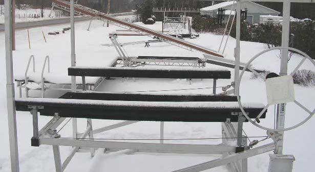
13 6. REPLACEMENTS & ADJUSTMENTS 6.1 LEG ADJUSTEMENT It is critical that each foot plate has a solid, flat base to rest on. It may be necessary to place a concrete slab (or similar) under each plate in order to maintain stability. Minor adjustments may be required after the boat has been placed on the lift (due to settling) to ensure that the desired level is maintained. WARNING: Before performing any adjustments, remove the boat from the lift and place the bunk in the fully raised position. FRONT REAR Note: it may be advisable to allow for fluctuations in water levels by placing the cross bar a few inches below the water level. It is also advisable to slightly tilt the lift towards the back so that any water in the boat can drain rearward toward the bilge when the boat is raised out of the water. Step 1 Loosen (but do not remove) both bolts on the front 2 leg brackets with a ¾ or 19mm wrench. This will allow the leg posts to move freely. Step 2 Adjust the front legs to the recommended height. The cross bar (shown) should sit just at or slightly below the water level. Using a spirit level, check for side-to-side alignment. Adjust the front leg(s) as required until unit is level. Step 3 Tighten both bolts on the front 2 leg brackets with a ¾ or 19mm wrench. Step 4 As in Step 1, loosen (but do not remove) both bolts on the rear 2 leg brackets with a ¾ or 19mm wrench. Adjust the rear legs so that the lift has a slight reward tilt. Step 5 - Using a spirit level, check for side-to-side and front-to-back alignment. Adjust the rear legs as required until the correct level is achieved. 13
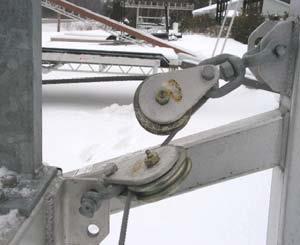
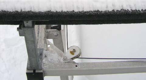
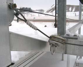
14 Step 6 - Tighten both bolts on the rear 2 leg brackets, as shown in Step CABLE REPLACEMENT WARNING: Before replacing the cable, remove the boat from the lift and place the bunk in the lowered position. Note: the instructions below are for a left hand mounted winch, you will need to flip the procedure for a right mounted winch and feed the cable onto the winch between the backside of the drum and the winch frame. Step 1 Securely connect looped end of wire cable to U-bolt on lift frame. Route cable down through 1 st pulley (located just underneath the U-bolt) as indicated on Diagram Step 2 Route cable horizontally across the frame and through 2 nd pulley system (located on opposite side of frame). Step 3 Route cable horizontally along frame and through 3 rd pulley. Step 4 Route cable horizontally across the frame and through 4 th pulley (located on opposite side of frame). Step 5 - Route cable up over the front of the winch drum. Clamp end with approx. 1 of cable extending beyond clamp. Wind up excess cable onto drum with minimal gaps between wraps. Ensure that cable does not rub against any part of winch frame or vertical lift. Step 6 Grease the mating surfaces of all stainless steel fasteners on all pulleys to ensure they turn freely. WARNING: Ensure clockwise rotation of the winch handle raises the platform and an audible click of the brake pawl is heard upon raising. 14


15 6.2.1 CABLE REPLACEMENT DIGRAM Step 3 Step Step 4 Step 1 15


16 6.3 BUNK ADJUSTMENT Our bunks are pre-set to properly fit the most common boat hull configurations. However, if you need to replace the bunks or change your boat, adjustments may be required. Note: if you change from a traditional V style hull to a ski boat with fins and shaft, the bunks must be replaced with a set of raised bunks to allow for additional clearance. On a standard V hull configuration, your boat should be positioned so that it is centered in the lift and forward just enough so that the rear taper on the bunk is visible just past the stern of the boats left and right side chines. For boats with I/O or an outboard motor, the boat should be positioned so that so that the rear taper on the bunk is visible just past the stern of the boat and not the extended swim platform. For ski boats or boats with fins and/or shaft drives, your boat should be positioned far enough forward so the propeller and rudder are behind the bed frame. WARNING: Before making any adjustments, remove the boat from the lift and place the bunk in the raised position Bunk Adjustment 1000lb lb Boatlift Step 1: Loosen the four 5/16 nuts on the U bolts (a ¾, 19mm or 5/8 wrench can be used) and slide the post to the desired location. Repeat on the other side. Step 2: Step 3: Tighten all bolts. Retry boat on bunks and continue to make adjustments until the correct position is achieved Bunk Adjustment 3000lb lb Boatlift Step 1: Loosen the two ¾ bolts and slide the post along the track to the desired location. Repeat on the other side. Step 2: Step 3: Tighten all bolts. Retry boat on bunks and continue to make adjustments until the correct position is achieved. 16
17 7. WARRANTY R & J Machine warrants all R & J Machine built equipment purchased new by the original owner to be free from defect in the material and workmanship under normal use for a period of 24 months from the original date of purchase (excluding components and options which carry their own manufacturer s warranty, wherein that warranty will apply). R & J Machine is not liable for indirect, incidental or consequential losses, damages or injuries of any kind due to installation, removal, use, misuse, misapplication or improper selection of one of our purchased or displayed products. R & J Machine agrees to repair or replace only defective parts returned to the factory (prepaid) and deemed defective by R & J Machine. Any repairs performed shall not extend the 24 month duration of this warranty. All PVC decking is warranted by the PVC manufacturer and must be returned to them. There is no other express warranty. Our warranty is void in any of the following circumstances: Equipment has been used beyond its rated capacity. Damage or defect has occurred due to repairs/services being completed by persons other than authorized service personnel. Damage has been caused by environmental factors which include (but are not limited to) airborne fallout, tree sap, fire, floods, storms, lightening & ice. Damage caused by accident, abuse or negligence, misuse, incorrect operation or improper adjustment. The product has been modified in any way by the customer once ownership has occurred. 17
18 18
LIFT 1200 SERIES ASSEMBLY AND MAINTENANCE MANUAL
 LIFT 1200 SERIES ASSEMBLY AND MAINTENANCE MANUAL 1 TABLE OF CONTENTS FIGURE DESCRIPTION PAGE 1 SAFETY 3-5 1.1 Introduction 3 1.2 Equipment Labels 3 1.3 Equipment & Personal Safety 3 1.4 Operating Safety
3000 WAVEX SERIES ASSEMBLY AND MAINTENANCE MANUAL
 3000 WAVEX SERIES ASSEMBLY AND MAINTENANCE MANUAL 1 TABLE OF CONTENTS FIGURE DESCRIPTION PAGE 1 SAFETY 3-5 1.1 Introduction 3 1.2 Equipment Labels 3 1.3 Equipment & Personal Safety 3 1.4 Operating Safety
VL 2K LIFT D-L WINCH INSTRUCTIONS (Applies to P/Ns , , , , , )
") VL 2K LIFT D-L WINCH INSTRUCTIONS (Applies to P/Ns 3714022, 3714028, 3714034, 3714040, 3714043, 3714046) REIMANN & GEORGER CORPORATION MARINE PRODUCTS BUFFALO, NY P/N 6112103 04/09/18 1 SAFETY 1.1 INTRODUCTION
VL 2K LIFT D-L WINCH INSTRUCTIONS (Applies to P/Ns 3714022, 3714028, 3714034, 3714040, 3714043, 3714046) REIMANN & GEORGER CORPORATION MARINE PRODUCTS BUFFALO, NY P/N 6112103 04/09/18 1 SAFETY 1.1 INTRODUCTION
VL SHEAVES/CABLE UPGRADE KIT INSTRUCTIONS
 VL SHEAVES/CABLE UPGRADE KIT INSTRUCTIONS RGC MARINE PRODUCTS BUFFALO, NY P/N 6112062 02/03/17 TABLE OF CONTENTS CHAPTER TITLE PAGE 1 SAFETY... 1 1.1 Introduction... 1 1.2 Safety Definitions... 1 1.3 Equipment
VL PONTOON/TRITOON DECK BRACKET 13 INSTRUCTIONS
 VL PONTOON/TRITOON DECK BRACKET 13 INSTRUCTIONS REIMANN & GEORGER CORPORATION MARINE PRODUCTS BUFFALO, NY P/N 6112--- 01/08/14 TABLE OF CONTENTS CHAPTER TITLE PAGE 1 SAFETY... 1 1.1 Introduction... 1 1.2
PL1200W BOAT LIFT INSTRUCTIONS
 E L PL1200W BOAT LIFT INSTRUCTIONS RA IS OWE R REIMANN & GEORGER CORPORATION MARINE PRODUCTS BUFFALO, NY P/N 6112053 03/09/05 TABLE OF CONTENTS CHAPTER TITLE PAGE 1 SAFETY...1 1.1 Introduction...1 1.2
Shoreline Cantilever Lift 2500lb Capacity Models: (108" inside width) - Part # (120" inside width) - Part #
 - Part # (120 inside width) - Part #") Shoreline Cantilever Lift 2500lb Capacity Models: 25108 (108" inside width) - Part # 1017402 25120 (120" inside width) - Part # 1017403 1. 2. 3. 4. 5. CAUTION - PUT SAFETY FIRST Before attempting to install
Shoreline Cantilever Lift 2500lb Capacity Models: 25108 (108" inside width) - Part # 1017402 25120 (120" inside width) - Part # 1017403 1. 2. 3. 4. 5. CAUTION - PUT SAFETY FIRST Before attempting to install
2,500/4,000 LB Easy Riser Vertical Cable Feighner Lift
 2,500/4,000 LB Easy Riser Vertical Cable Feighner Lift CAUTION - PUT SAFETY FIRST 1. Before attempting to install or operate this lift, study and fully understand the proper operating procedures and safety
VL20100 VERTICAL LIFT INSTRUCTIONS
 VL20100 VERTICAL LIFT INSTRUCTIONS REIMANN & GEORGER CORPORATION MARINE PRODUCTS BUFFALO, NY P/N 6112058 09/25/17 PRE-LIFTING CHECKLIST The lift and related equipment must be thoroughly inspected prior
QUALITY ALUMINUM BOAT LIFTS, INC. INSTRUCTIONS. Dominator Lake Lift
 INSTRUCTIONS Dominator Lake Lift PHONE:251-986-3882 * FAX:251-986-3136 QABLDOMINATORINST.2014 P a g e 1 Quality Aluminum Boat Lifts, INC. Installation Instructions: Dominator Lake Lift Thank you for your
VL3500 VERTICAL LIFT INSTRUCTIONS
 VL3500 VERTICAL LIFT INSTRUCTIONS REIMANN & GEORGER CORPORATION MARINE PRODUCTS BUFFALO, NY P/N 6113631 3/11/16 PRE-LIFTING CHECKLIST The lift and related equipment must be thoroughly inspected prior to
VL 45108, VL45116, VL45116 TALL & VL40124P VERTICAL LIFT INSTRUCTIONS
 VL 45108, VL45116, VL45116 TALL & VL40124P VERTICAL LIFT INSTRUCTIONS REIMANN & GEORGER CORPORATION MARINE PRODUCTS BUFFALO, NY P/N 6113641 3/03/17 PRE-LIFTING CHECKLIST The lift and related equipment
Assembly Instructions. -Cantilever Boat Lifts
 Assembly Instructions -Cantilever Boat Lifts Winch Instruction Page Safety Information 1. The winch is built for the multipurpose of hauling and lifting operations. It is not to be used as a hoist for
VL 45108, VL45116, VL45116 TALL & VL40124P VERTICAL LIFT INSTRUCTIONS
 VL 45108, VL45116, VL45116 TALL & VL40124P VERTICAL LIFT INSTRUCTIONS REIMANN & GEORGER CORPORATION MARINE PRODUCTS BUFFALO, NY P/N 6113641 3/19/14 TABLE OF CONTENTS CHAPTER TITLE PAGE 1 SAFETY... 1 1.1
VL6K & 6KT VERTICAL LIFT INSTRUCTIONS
 VL6K & 6KT VERTICAL LIFT INSTRUCTIONS REIMANN & GEORGER CORPORATION MARINE PRODUCTS BUFFALO, NY P/N 6113662 3/19/14 TABLE OF CONTENTS CHAPTER TITLE PAGE 1 SAFETY... 1 1.1 Introduction... 1 1.2 Safety
OPERATIONS/PARTS MANUAL FOR PATTERSON'S WWP75H-10 HYDRAULIC WINCH.
 W. W. Patterson Company 3 Riversea Road Pittsburgh, PA 15233 Phone: 800-322-2018 FAX: 412-322-2785 OPERATIONS/PARTS MANUAL FOR PATTERSON'S WWP75H-10 HYDRAULIC WINCH. Please fill in the following blanks
Chapter 2 Rigging. Cutting Wire Rope. Anchoring Wire Rope to Drum. Winding Wire Rope Onto Drum
 Chapter 2 Rigging Cutting Wire Rope The wire rope must be tightly seized on both sides of the point where the wire rope will be cut, as shown in Figure 2-1. Seize the wire rope with either seizing wire
600 / 600FC OWNER'S MANUAL
 PROGRESSION 600 / 600FC OWNER'S MANUAL Issue 2 / Version E - Dec. 10, 1997 Copyright 1997 GAMMA Sports - All Rights Reserved PROGRESSION 600 / 600FC OWNER'S MANUAL TABLE OF CONTENTS PAGE 1... WARRANTY
2000 lb manual winch
 2000 lb manual winch Model 41694 Operation Instructions Due to continuing improvements, actual product may differ slightly from the product described herein. 3491 Mission Oaks Blvd., Camarillo, CA 93011
VL5K & 5KT SR09 VERTICAL LIFT INSTRUCTIONS
 VL5K & 5KT SR09 VERTICAL LIFT INSTRUCTIONS REIMANN & GEORGER CORPORATION MARINE PRODUCTS BUFFALO, NY P/N 6113651 05/22/17 PRE-LIFTING CHECKLIST The lift and related equipment must be thoroughly inspected
CAUTION - PUT SAFETY FIRST
 www.shoremaster.com DVS Vertical Lift (Double V Side): Frame ssembly Instructions. Models: 500DVS - 0ft Wide, 5000lb Capacity - Part #: 0079 600DVS - 0ft Wide, 6000lb Capacity - Part #: 0033.. 3.. 5. CUTION
Marine 6-Boat Free-Standing Racks SKU: Updated November 2011
 Marine 6-Boat Free-Standing Racks SKU: 30-061 Updated November 011 Contains: Marine -Boat Free-Standing Racks (SKU 1-003) Marine 3 rd Boat Expansion Racks (SKU 1-0303) Marine Back Legs (SKU -001) 3 Sets
OPERATIONS/PARTS MANUAL FOR PATTERSON'S WWP50-H-14 HYDRAULIC WINCH.
 W. W. Patterson Company 3 Riversea Road Pittsburgh, PA 15233 Phone: 800-322-2018 FAX: 412-322-2785 OPERATIONS/PARTS MANUAL FOR PATTERSON'S WWP50-H-14 HYDRAULIC WINCH. Please fill in the following blanks
TrekMill USER'S MANUAL MM5050
 Read the safety and comfort guide in this manual before using this equipment. USER'S MANUAL TrekMill MM5050 Serial Number: Date Purchased: Find the serial number in the location shown below. CONTENTS Safety
OPERATION and MAINTENANCE Guide
 Catalog No. AIR1000 Winch and Hoist OPERATION and MAINTENANCE Guide Cat. No. AIR1000 1250 Lb. Single Line Pull READ THIS BEFORE OPERATING UNIT INSTALLATION: Mount on clean, flat surface. Use 1/2" mounting
Operator s Manual Series 2400 Material Lift
 October 2013 Operator s Manual Series 2400 Material Lift USA 7514 Alabonson Rd. Houston, TX 77088 ph: 281-999-6900 fax: 281-999-6966 CANADA 75 Saltsman Drive, Unit 5 Cambridge, Ontario N3H 4R7 ph: 519-653-5300
C - SERIES. Height Adjustable Portable Goal Supports. Installation & Owner s Instructions C1000 C2000. Made in the USA
 C - SERIES Height Adjustable Portable Goal Supports C1000 C2000 Installation & Owner s Instructions Made in the USA This manual explains the proper installation, operation, and maintenance of your Schutt
OWNERS MANUAL. Model Shown with optional Primary Mooring Cleats. Portable Mooring System SAFETY OPERATION MAINTENANCE PARTS
 OWNERS MANUAL Model 2400 Shown with optional Primary Mooring Cleats. Portable Mooring System SAFETY OPERATION MAINTENANCE PARTS CAUTION: Before using your new Pier Tender, read rules for Safety, Operation,
OPERATIONS/PARTS MANUAL FOR PATTERSON'S WWP40M-12 and all WIDE DRUM variations of this HAND OPERATED WINCH.
 W. W. Patterson Company 3 Riversea Road Pittsburgh, PA 15233 Phone: 800-322-2018 FAX: 412-322-2785 OPERATIONS/PARTS MANUAL FOR PATTERSON'S WWP40M-12 and all WIDE DRUM variations of this HAND OPERATED WINCH.
3K SINGLE TRACK OWNERS MANUAL
 When It s Done Right...It s Golden! 3K SINGLE TRACK OWNERS MANUAL ISO 9001:2008 Quality Management System DEALER INSTALLATION DATE OWNER S NAME SERIAL NUMBER CONGRATULATIONS ON YOUR PURCHASE OF A GOLDEN
602 STRINGING MACHINE OWNER'S MANUAL
 PROGRESSION 602 STRINGING MACHINE OWNER'S MANUAL AL Issue 1- April 2000 Copyright 2000 GAMMA Sports - All Rights Reserved PROGRESSION 602 STRINGING MACHINE TABLE OF CONTENTS PAGE 1... WARRANTY PAGE 2...
Instruction Manual. PE Pipe Squeeze-off Tool Model TR650
 PE Pipe Squeeze-off Tool Model TR650 Instruction Manual For your personal safety READ and UNDERSTAND instructions before using tools. SAVE these instructions for future reference. SPECIFICATIONS Table
For ANCHOR WINCH Model: T Big Water 45 T sw Salt Water Series Big Water 45
 INSTALLATION AND OPERATING INSTRUCTIONS ANCHOR WINCHES For ANCHOR WINCH Model: T10110-45 Big Water 45 T10103-45sw Salt Water Series Big Water 45 If you have any questions or difficulty installing this
SASK-A-POLE OWNERS AND USERS MANUAL
 SASK-A-POLE OWNERS AND USERS MANUAL GENERAL INFORMATION The Saskatchewan Abilities Council s Sask-a-Pole accessibility and transfer aid is designed to help provide safe and easy access to chairs, beds,
For ELECTRIC ANCHOR WINCH Models: T Pontoon 35 T sw Salt Water Series Coastal 35
 INSTALLATION AND OPERATING INSTRUCTIONS ANCHOR WINCHES For ELECTRIC ANCHOR WINCH Models: T10109-35 Pontoon 35 T10102-35sw Salt Water Series Coastal 35 If you have any questions or difficulty installing
RADROVER REAR RACK INSTALLATION MANUAL
 RADROVER REAR RACK INSTALLATION MANUAL WWW.RADPOWERBIKES.COM We are here to help! Please contact us at SUPPORT@RADPOWERBIKES.COM or 1-800-939-0310 if you have questions. REV022216 Welcome Thanks you for
OPERATIONS/PARTS MANUAL FOR PATTERSON'S HAND OPERATED WINCH
 DOC # 5071-A W. W. Patterson Company 3 Riversea Road Pittsburgh, PA 15233 Phone: 800-322-2018 FAX: 412-322-2785 OPERATIONS/PARTS MANUAL FOR PATTERSON'S HAND OPERATED WINCH Please fill in the following
Vertical Lift: Frame Assembly Instructions. Model: ft Wide 7000lb Capacity - Part #:
 www.shoremaster.com 70068 Vertical Lift: Frame ssembly Instructions. Model: 70068-0ft Wide 7000lb apacity - Part #: 0070. 2. 3.. 5. UTION - PUT SFETY FIRST Before attempting to install or operate this
STYRIGGER PRODUCT MANUAL
 STYRIGGER PRODUCT MANUAL Thank you for choosing the Styrigger kayak and canoe stabilizer. A kayak or canoe equipped with a Styrigger (safety outrigger) is an excellent choice for a beginner or someone
OWNER'S MANUAL. Copyright 2003 GAMMA - All Rights Reserved
 OWNER'S MANUAL AL Issue 1 - December 2003 Copyright 2003 GAMMA - All Rights Reserved OWNER'S MANUAL TABLE OF CONTENTS PAGE 1... WARRANTY PAGE 2... ASSEMBLY INSTRUCTIONS PAGE 4... MOUNTING THE RACQUET PAGE
OPERATORS MANUAL MODEL 365 BACK LAPPING MACHINE WARNING
 MODEL 365 BACK LAPPING MACHINE OPERATORS MANUAL WARNING You must thoroughly read and understand this manual before operating the equipment, paying particular attention to the Warning & Safety instructions.
OPERATIONS/PARTS MANUAL FOR PATTERSON'S MODEL # WWP40M-LPS-6 LOW-PROFILE BARGE CONNECTOR WINCH
 W. W. Patterson Company 3 Riversea Road Pittsburgh, PA 15233 Phone: 800-322-2018 FAX: 412-322-2785 OPERATIONS/PARTS MANUAL FOR PATTERSON'S MODEL # WWP40M-LPS-6 LOW-PROFILE BARGE CONNECTOR WINCH Please
SKYBIRD TRAP OWNER S / OPERATOR S MANUAL PARTS AND ASSEMBLY INSTRUCTIONS
 SKYBIRD TRAP PART NO. 40903 OWNER S / OPERATOR S MANUAL PARTS AND ASSEMBLY INSTRUCTIONS WARNING: THIS MACHINE CAN CAUSE SERIOUS INJURY OR DEATH! THOROUGHLY READ INSTRUCTIONS AND SAFETY INFORMATION BEFORE
ATD /8 x 50 Retractable Air Hose Reel Owner s Manual
 ATD-31166 3/8 x 50 Retractable Air Hose Reel Owner s Manual Features Heavy-gauge, all-steel reel assembly 8-position ratchet mechanism locks reel at desired hose length 5-position adjustable roller outlet
OPERATIONS and SAFETY MANUAL
 OPERATIONS and SAFETY MANUAL LIFETIME WARRANTY SPECIAL SAFETY FEATURES: 1. Hook starts to open when device exceeds weight limit. 2. Latch Pops when weight is exceeded. At this point remove the load from
GUIDELINES FOR USE GUARD
 GUIDELINES FOR USE GUARD G Guard Range of Load Arrestors Retractable Fall Arrest Safety Line for Protection of Machinery & Sensitive Loads GLOBESTOCK MILE OAK INDUST. ESTATE, MAESBURY ROAD, OSWESTRY, SHROPSHIRE
AC1810 / AC1810-A TECHNICAL SPECIFICATIONS. Operating Pressure psi ( kgs/cm²) [AC1810] Displacement. Net Weight
![AC1810 / AC1810-A TECHNICAL SPECIFICATIONS. Operating Pressure psi ( kgs/cm²) [AC1810] Displacement. Net Weight](/thumbs/83/88369739.jpg "AC1810 / AC1810-A TECHNICAL SPECIFICATIONS. Operating Pressure psi ( kgs/cm²) [AC1810] Displacement. Net Weight") Technical Specifications Operating Instructions Maintenance Information Troubleshooting Guide Parts Diagrams AC1810 / AC1810-A THE EVOLUTION OF PERFECTION CAUTION: Before attempting to use or service this
Technical Specifications Operating Instructions Maintenance Information Troubleshooting Guide Parts Diagrams AC1810 / AC1810-A THE EVOLUTION OF PERFECTION CAUTION: Before attempting to use or service this
Thank you for purchasing a Porta-Dock product! *Please read and follow these instructions step by step*
 PG 1 OF 9 PORTA-DOCK, INC. 74A ABL/APW 1056 & 44A FLB APW 1056 PORTA-LIFT Thank you for purchasing a Porta-Dock product! *Please read and follow these instructions step by step* STEP 1. Separate and group
OWNER'S MANUAL. Copyright 1999 ATS - All Rights Reserved
 OWNER'S MANUAL AL Issue 2 - August 19, 1999 Copyright 1999 ATS - All Rights Reserved OWNER'S MANUAL TABLE OF CONTENTS PAGE 1... WARRANTY PAGE 2... ASSEMBLY INSTRUCTIONS PAGE 4... MOUNTING THE RACQUET PAGE
This document to be used with Hurley traditional Davits
 ~ InstructIon Manual ~ This document to be used with Hurley traditional Davits WarnIngs WarnIng - Failure to install, maintain, protect, and operate the system properly can cause malfunction resulting
Sunset Swings By Health in Motion, LLC
 Sunset Swings By Health in Motion, LLC Model 421 Lounge Swing Assembly and Operation Manual Record Serial Number Here www.sunsetswings.com by Health In Motion, LLC. 1/30/2013 Caution: READ! VERY IMPORTANT
HYDRAULIC WINCH FOR AUGERS UP TO WR10 X 71 / W130 X 41 ASSEMBLY & OPERATION MANUAL
 HYDRAULIC WINCH ASSEMBLY & OPERATION MANUAL Read this manual before using product. Failure to follow instructions and safety precautions can result in serious injury, death, or property damage. Keep manual
I.H.S INSTALLATION INSTRUCTIONS
 I.H.S INSTALLATION INSTRUCTIONS TOOLS REQUIRED The following tools will be required for installation of your I.H.S. system. Item Qty Needed 9/16 Open End Wrench 2 3/4 Open End Wrench 1 1/2 Open End Wrench
Operator s Manual. 2010, 2015, 2020, 2025 Material Lifts
 July 2017 Operator s Manual 2010, 2015, 2020, 2025 Material Lifts! Before operating this lift, read and understand this Operator s Manual. Become familiar with the potential hazards of this unit. Call
Operator s Manual. Series 2100 Contractor Lifts
 October 2013 Operator s Manual Series 2100 Contractor Lifts! Before operating this lift, read and understand this Operator s Manual. Become familiar with the potential hazards of this unit. Call SUMNER
Fiber Cable Puller with Tuf-Lugger lite
 7 OPERATING INSTRUCTION MANUAL Fiber Cable Puller with Tuf-Lugger lite Copyright 2015 DCD Design & Manufacturing Ltd. Revision 1.0 IMPORTANT SAFETY INSTRUCTIONS READ ALL INSTRUCTIONS BEFORE USING The Fiber
X-6 STRINGING MACHINE OWNER'S MANUAL. Issue 1 - May Copyright 2004 GAMMA Sports - All Rights Reserved
 X-6 STRINGING MACHINE OWNER'S MANUAL Issue 1 - May 2004 Copyright 2004 GAMMA Sports - All Rights Reserved OWNER'S MANUAL GAMMA X-6 TABLE OF CONTENTS PAGE 1... WARRANTY PAGE 2... FEATURES PAGE 3...ASSEMBLY
DRAG HARROW SAFETY & OPERATING INSTRUCTIONS. Original Language. Serial No. Order No.
 DR ` DRAG HARROW SAFETY & OPERATING INSTRUCTIONS Serial No. Order No. Original Language DR Power Equipment Toll-free phone: 1-800-DR-OWNER (376-9637) Fax: 1-802-877-1213 Website: www.drpower.com Read and
Installation and service should be performed by a qualified service professional.
 Damage to your lift or vessel can result from improper initial setup of the system. Consult a HydroHoist Certified Installer for initial setup and support Installation and service should be performed by
Page 1. Single Scull Car Rack Assembly and User s Manual " "
 Page 1 Single Scull Car Rack Assembly and User s Manual Page 2 Items in the box: (2) V cradles (2) 4 rails (1) 1 3/4 X 18 rail coupler (4) 1/4-20 X 4 1/2 bolts (2) 1/4-20 X 2 1/2 bolts (12) 1/4 flat washers
OWNER'S MANUAL FISHING AND PONTOON BOAT ANCHOR WINCH. 24' Class Rope Anchor Winch
 OWNER'S MANUAL 24' Class Rope Anchor Winch FISHING AND PONTOON BOAT ANCHOR WINCH PW24101 The 24 Class anchor winch is a 12VDC power winch that retrieves and deploys river, mushroom, or navy type anchors
OPERATING and MAINTENANCE INSTRUCTIONS MAXIS 3K Puller (M3K-M)
") OPERATING and MAINTENANCE INSTRUCTIONS MAXIS 3K Puller (M3K-M) 04/17 (M3K-M) READ AND UNDERSTAND ALL OF THE INSTRUCTIONS AND SAFETY INFORMATION IN THIS MANUAL BEFORE OPERATING OR SERVICING THIS TOOL TABLE
OPERATING and MAINTENANCE INSTRUCTIONS MAXIS 3K Puller (M3K-M) 04/17 (M3K-M) READ AND UNDERSTAND ALL OF THE INSTRUCTIONS AND SAFETY INFORMATION IN THIS MANUAL BEFORE OPERATING OR SERVICING THIS TOOL TABLE
DIRECT DRIVE DIXIE DOUBLE SEAMER Model 25D
 OPERATOR'S MANUAL DIRECT DRIVE DIXIE DOUBLE SEAMER Model 25D LUBRICATE DAILY: A. Gears inside gear housing at chuck shaft (1) Oil B. Seam rolls and cam rolls (4) - Oil C. Seam roll levers through gear
USER MANUAL
 C Cimarron Sports 1-888-816-6517 www.cimarronsports.com Combo Pitching Machine USER MANUAL TABLE OF CONTENTS Thank you for purchasing the Cimarron Combo Pitching Machine. The Cimarron Combo Pitching Machine
310 SERIES TILT-TO-LOAD ROTATOR. The Specialist In Drum Handling Equipment
 OPERATOR S MANUAL FOR MORSE TILT-TO-LOAD DRUM ROTATOR SAFETY INFORMATION: While Morse Manufacturing Co. drum handling equipment is engineered for safety and efficiency, a high degree of responsibility
Steel Spring Driven Reel Instruction Manual
 Steel Spring Driven Reel Instruction Manual WARNING: Read carefully and understand all INSTRUCTIONS before operating. Failure to follow the safety rules and other basic safety precautions may result in
DBI SALA Confined Space Rescue Davit System
 Instructions for the following series products: Rescue Davit System (See back page for specific model numbers.) User Instruction Manual For Davit Rescue System This manual should be used as part of an
OPERATING and MAINTENANCE INSTRUCTIONS MAXIS 6K Puller (M6K-M)
") OPERATING and MAINTENANCE INSTRUCTIONS MAXIS 6K Puller (M6K-M) READ AND UNDERSTAND ALL OF THE INSTRUCTIONS AND SAFETY INFORMATION IN THIS MANUAL BEFORE OPERATING OR 04/17 (M6K-M) SERVICING THIS TOOL TABLE
OPERATING and MAINTENANCE INSTRUCTIONS MAXIS 6K Puller (M6K-M) READ AND UNDERSTAND ALL OF THE INSTRUCTIONS AND SAFETY INFORMATION IN THIS MANUAL BEFORE OPERATING OR 04/17 (M6K-M) SERVICING THIS TOOL TABLE
2018 ACCESSORY ATTACHMENTS OWNER S MANUAL
 2018 ACCESSORY ATTACHMENTS OWNER S MANUAL WWW.RADPOWERBIKES.COM We are here to help! Please contact us at SUPPORT@RADPOWERBIKES.COM or 1-800-939-0310 if you have questions. REV031418 Welcome Thanks you
Dual Release Walkers 6291 Series. 1 General. 1.1 Symbols WARNING
 User Manual DEALER: This manual MUST be given to the user of the product. USER: BEFORE using this product, read this manual and save for future reference. Dual Release Walkers 6291 Series EN User Manual...page
InstallatIon and owner s InstrUCtIons
 InstallatIon and owner s InstrUCtIons Wall Mount Series Adjustable and Fixed Height Goal Systems table of Contents Safety Instructions... 2 Goal Specifications... 3 Frame Attachment... 4 Frame Assembly
Owner s Manual. For. PWC 3000 Boat Lifts
 Owner s Manual For PWC 3000 Boat Lifts P a g e 2 SAFETY PRECAUTIONS 1. Your boat lift is a heavy duty piece of equipment. It is important that all persons that may operate this unit have read and understood
User Instruction Manual For Davit Rescue System
 Instructions for the following series products: Rescue Davit System Model numbers 8004000 and 8302500 User Instruction Manual For Davit Rescue System This manual should be used as part of an employee training
INSTALLATION AND OPERATING INSTRUCTIONS. T10219-AD Deckboat 40 with AutoDeploy and Wireless Remote Control
 INSTALLATION AND OPERATING INSTRUCTIONS ANCHOR WINCH T10219-AD Deckboat 40 with AutoDeploy and Wireless Remote Control If you have any questions or difficulty installing this product, we are here to help!
222 Schwinn Recumbent Exercise Bike Parts List Full Size Hardware Chart Product Illustration Assembly Instructions
 222 Schwinn Recumbent Exercise Bike Parts List Full Size Hardware Chart Product Illustration Assembly Instructions FITNESS SAFEGUARDS AND WARNINGS Before starting any exercise program, consult with your
OWNER'S MANUAL FREE FALL ROPE AND CHAIN ANCHOR WINCH. 12 Volt Powered Winch Power-In / Freewheel-out operation. 36', 41' and 46' Class Anchor Winch
 OWNER'S MANUAL 36', 41' and 46' Class Anchor Winch FREE FALL ROPE AND CHAIN ANCHOR WINCH PW46101 12 Volt Powered Winch Power-In / Freewheel-out operation These instructions apply to all models listed.
7130 Lancer Rear Drive Magnetic Commercial Indoor Cycling Bike
 7130 Lancer Rear Drive Magnetic Commercial Indoor Cycling Bike Owner s Manual Made in Taiwan INDEX IMPORTANT SAFETY INFORMATION... 1 EXPLODED DRAWING... 2 PARTS LIST... 3 ASSEMBLY INSTRUCTION... 4-9 USER
3/8" Dr. Air Butterfly Impact Wrench
 8192106 3/8" Dr. Air Butterfly Impact Wrench Owner s Manual Read and understand all instructions before use. Retain this manual for future reference. Specifications Construction: Polished aluminum and
SETTING THE HANDLE HEIGHT ON THE ROLLATOR
 Model No: Maximum User Weight: 10910C (Lightweight) 10928C (Heavy duty) 125kg (20st) (Lightweight) 170kg (27st) (Heavy duty) Height of handles: 780-915mm (30.5-36 ) (Lightweight) 790-930mm (31-36.5 ) (Heavy
Dual Release Walkers 6291 Series. 1 General. 1 Dual Release Walkers. 1.1 Symbols WARNING
 User Manual DEALER: This manual MUST be given to the user of the product. USER: BEFORE using this product, read this manual and save for future reference. Dual Release Walkers 6291 Series EN User Manual...page
CRANE WITH WINCH USE AND MAINTENANCE MANUAL. Code Rev. Release MD /03
 CRANE WITH WINCH Code Rev. Release MD.0.097 0 06/03 USE AND MAINTENANCE MANUAL CONTENTS 1 FOREWORD page 3 1.1 Description of the crane with winch page 3 2 USE OF THE CRANE WITH WINCH page 3 2.1 General
8MAY15 US RACK, Inc Falcon Drive, Madera, CA
 8MAY15 US RACK, Inc. - 2850 Falcon Drive, Madera, CA 93637-559-661-3050 INSTRUCTIONS for Bedrail-mounted MOTORCYCLE RACK, Model 2001-4TRA WARNING: Do NOT attempt to install or use this rack without following
Booster Pump PB4-60 Replacement Kits
 Booster Pump PB4-60 Replacement Kits FOR YOUR SAFETY - This product must be installed and serviced by a contractor who is licensed and qualified in pool equipment by the jurisdiction in which the product
453 Series Steam Heated Vaporizing Regulator
 ADI 0453A Certified ISO 9001:2000 453 Series Steam Heated Vaporizing Regulator INSTALLATION AND OPERATION INSTRUCTIONS Before Installing or Operating, Read and Comply with These Instructions Controls Corporation
RAVE SUP STAND UP PADDLE BOARD User Guide/Owner s Manual
 RAVE SUP STAND UP PADDLE BOARD User Guide/Owner s Manual ! W A R N I N G This product is not a lifesaving device. Always wear a nationally approved personal floatation device when using this product. Not
SIGNATURE DEF REELS Models: Bare Reel Reel Reel Reel
 SERVICE BULLETIN SB2023 Rev C 7/11 SIGNATURE DEF REELS Models: 2400-006 Bare Reel 2400-007 16 Reel 2400-008 20 Reel 2400-009 30 Reel Thoroughly read and understand this manual before installing, operating
OPERATIONS MANUAL IMPORTANT SAFETY INFORMATION
 OPERATIONS MANUAL IMPORTANT SAFETY INFORMATION Please read, understand and follow all safety information contained in these instructions prior to the use of this tool. Retain these instructions for further
Misaligned Folds Paper Feed Problems Double Feeds Won t Feed FLYER Won t Run iii
 Operator s Manual Table of Contents Operator Safety... 1 Introduction... 2 Unpacking and Setup... 3 Unpacking... 3 Setup... 4 FLYER Overview... 5 FLYER Diagram... 5 Capabilities... 5 Control Panel... 6
SVS MINI 4 LIFT INSTALLATION INSTRUCTIONS (220V)
") SVS MINI 4 LIFT INSTALLATION INSTRUCTIONS (220V) SVS, INC. 2513 Jenks Ave Panama City, FL 32405 www.svslifts.com Lifting Your Image Tel: 850-522-4747 Fax: 850-522-4739 sales@svslifts.com International
SVS MINI 4 LIFT INSTALLATION INSTRUCTIONS (220V) SVS, INC. 2513 Jenks Ave Panama City, FL 32405 www.svslifts.com Lifting Your Image Tel: 850-522-4747 Fax: 850-522-4739 sales@svslifts.com International
MANUAL SEALLESS STEEL STRAPPING TOOL MODEL A
 OPERATION MANUAL / SPARE PARTS LIST MANUAL SEALLESS STEEL STRAPPING TOOL MODEL A337.0001 13.1912.01 13191201.en/MAS/ 10.02 INDEX PAGE 1 SAFETY INSTRUCTIONS 2 2 WARRANTY CONDITIONS AND LIABILITY 4 3 APPROPRIATE
Parts and Owners Manual
 Parts and Owners Manual MOWER MODEL: SERIAL: ENGINE MODEL & HP: DATE PURCHASED: PURCHASED FROM: You must receive special training from the dealer before operating this mower. 9/30/2005 Commercial Mower
BUTTERFLY VALVES Series 800
 BUTTERFLY VALVES Series 800 WARNING Before proceeding read ALL instructions and become familiar with the equipment and associated drawings. Follow ALL applicable safety regulations and codes for pressurized
accidents which arise due to non-observance of these instructions and the safety information herein. SPECIFICATIONS
 18 GAUGE 2 INCH BRAD NAILER Model: 7555 CALIFORNIA PROPOSITION 65 WARNING: You can create dust when you cut, sand, drill or grind materials such as wood, paint, metal, concrete, cement, or other masonry.
accidents which arise due to non-observance of these instructions and the safety information herein. SPECIFICATIONS
 18 GAUGE 1-1/4 INCH BRAD NAILER Model: 7611 CALIFORNIA PROPOSITION 65 WARNING: You can create dust when you cut, sand, drill or grind materials such as wood, paint, metal, concrete, cement, or other masonry.
OPERATIONS/PARTS MANUAL FOR PATTERSON'S WWP40BC BARGE CONNECTOR WINCH
 W. W. Patterson Company 3 Riversea Road Pittsburgh, PA 15233 Phone: 800-322-2018 FAX: 412-322-2785 OPERATIONS/PARTS MANUAL FOR PATTERSON'S WWP40BC BARGE CONNECTOR WINCH Please fill in the following blanks
20 Ton SD Shop Press Operating Instructions
 20 Ton SD Shop Press Operating Instructions MODEL NO. 850SD Hazard Symbols Used in the Manuals This manual includes the hazard symbols defined below when the operations or maintenance job involves a potential
X-6FC STRINGING MACHINE OWNER'S MANUAL. Issue 1 - May Copyright 2004 GAMMA Sports - All Rights Reserved
 X-6FC STRINGING MACHINE OWNER'S MANUAL Issue 1 - May 2004 Copyright 2004 GAMMA Sports - All Rights Reserved OWNER'S MANUAL GAMMA X-6FC TABLE OF CONTENTS PAGE 1... WARRANTY PAGE 2... FEATURES PAGE 3...
Instruction Sheet. CP2000: 2000 lb Cable Puller IMPORTANT RECEIVING INSTRUCTIONS SAFETY ISSUES
 Instruction Sheet CP2000: 2000 lb Cable Puller RPS-0148 07/02 IMPORTANT RECEIVING INSTRUCTIONS Visually inspect all components for shipping damage. If shipping damage is found, notify carrier at once.
General No. 25 and D-25 Handy Operating Instructions
 General No. 25 and D-25 Handy For 1-1/4 through 3 lines (30mm 75mm) No. 25 Handy D- 25 Handy This tool is designed to give you years of trouble-free, profitable service. However, no machine is better than
DLx1200, DLx1500, DLx1900, DLx2300 PULLING WINCHES. U.S. Patent Canadian Patent Model #DLx1200
 DLx1200, DLx1500, DLx1900, DLx2300 PULLING WINCHES U.S. Patent 6116580 Canadian Patent 2378538 Model #DLx1200 WARNING READ INSTRUCTIONS CAREFULLY BEFORE ATTEMPTING TO INSTALL, OPERATE OR SERVICE THIS WINCH.